US6695627B2 - Profiled header ground pin - Google Patents
Profiled header ground pinDownload PDFInfo
- Publication number
- US6695627B2 US6695627B2US09/921,352US92135201AUS6695627B2US 6695627 B2US6695627 B2US 6695627B2US 92135201 AUS92135201 AUS 92135201AUS 6695627 B2US6695627 B2US 6695627B2
- Authority
- US
- United States
- Prior art keywords
- pin
- stem
- tip
- section
- height
- Prior art date
- Legal status (The legal status is an assumption and is not a legal conclusion. Google has not performed a legal analysis and makes no representation as to the accuracy of the status listed.)
- Expired - Lifetime, expires
Links
- 230000013011matingEffects0.000abstractdescription6
- 238000003780insertionMethods0.000description6
- 230000037431insertionEffects0.000description6
- 238000010276constructionMethods0.000description3
- 229920000642polymerPolymers0.000description2
- 230000002028prematureEffects0.000description2
- 229910000906BronzeInorganic materials0.000description1
- OAICVXFJPJFONN-UHFFFAOYSA-NPhosphorusChemical compound[P]OAICVXFJPJFONN-UHFFFAOYSA-N0.000description1
- 239000000853adhesiveSubstances0.000description1
- 230000001070adhesive effectEffects0.000description1
- DMFGNRRURHSENX-UHFFFAOYSA-Nberyllium copperChemical compound[Be].[Cu]DMFGNRRURHSENX-UHFFFAOYSA-N0.000description1
- 230000005540biological transmissionEffects0.000description1
- 239000010974bronzeSubstances0.000description1
- KUNSUQLRTQLHQQ-UHFFFAOYSA-Ncopper tinChemical compound[Cu].[Sn]KUNSUQLRTQLHQQ-UHFFFAOYSA-N0.000description1
- 238000002955isolationMethods0.000description1
- 238000004519manufacturing processMethods0.000description1
- 239000000463materialSubstances0.000description1
- 239000004033plasticSubstances0.000description1
- 229920001169thermoplasticPolymers0.000description1
- 239000004416thermosoftening plasticSubstances0.000description1
Images


Classifications
- H—ELECTRICITY
- H01—ELECTRIC ELEMENTS
- H01R—ELECTRICALLY-CONDUCTIVE CONNECTIONS; STRUCTURAL ASSOCIATIONS OF A PLURALITY OF MUTUALLY-INSULATED ELECTRICAL CONNECTING ELEMENTS; COUPLING DEVICES; CURRENT COLLECTORS
- H01R13/00—Details of coupling devices of the kinds covered by groups H01R12/70 or H01R24/00 - H01R33/00
- H01R13/02—Contact members
- H01R13/04—Pins or blades for co-operation with sockets
- H—ELECTRICITY
- H01—ELECTRIC ELEMENTS
- H01R—ELECTRICALLY-CONDUCTIVE CONNECTIONS; STRUCTURAL ASSOCIATIONS OF A PLURALITY OF MUTUALLY-INSULATED ELECTRICAL CONNECTING ELEMENTS; COUPLING DEVICES; CURRENT COLLECTORS
- H01R12/00—Structural associations of a plurality of mutually-insulated electrical connecting elements, specially adapted for printed circuits, e.g. printed circuit boards [PCB], flat or ribbon cables, or like generally planar structures, e.g. terminal strips, terminal blocks; Coupling devices specially adapted for printed circuits, flat or ribbon cables, or like generally planar structures; Terminals specially adapted for contact with, or insertion into, printed circuits, flat or ribbon cables, or like generally planar structures
- H01R12/70—Coupling devices
- H01R12/82—Coupling devices connected with low or zero insertion force
- H—ELECTRICITY
- H01—ELECTRIC ELEMENTS
- H01R—ELECTRICALLY-CONDUCTIVE CONNECTIONS; STRUCTURAL ASSOCIATIONS OF A PLURALITY OF MUTUALLY-INSULATED ELECTRICAL CONNECTING ELEMENTS; COUPLING DEVICES; CURRENT COLLECTORS
- H01R12/00—Structural associations of a plurality of mutually-insulated electrical connecting elements, specially adapted for printed circuits, e.g. printed circuit boards [PCB], flat or ribbon cables, or like generally planar structures, e.g. terminal strips, terminal blocks; Coupling devices specially adapted for printed circuits, flat or ribbon cables, or like generally planar structures; Terminals specially adapted for contact with, or insertion into, printed circuits, flat or ribbon cables, or like generally planar structures
- H01R12/70—Coupling devices
- H01R12/71—Coupling devices for rigid printing circuits or like structures
- H01R12/72—Coupling devices for rigid printing circuits or like structures coupling with the edge of the rigid printed circuits or like structures
- H01R12/722—Coupling devices for rigid printing circuits or like structures coupling with the edge of the rigid printed circuits or like structures coupling devices mounted on the edge of the printed circuits
- H01R12/724—Coupling devices for rigid printing circuits or like structures coupling with the edge of the rigid printed circuits or like structures coupling devices mounted on the edge of the printed circuits containing contact members forming a right angle
- H—ELECTRICITY
- H01—ELECTRIC ELEMENTS
- H01R—ELECTRICALLY-CONDUCTIVE CONNECTIONS; STRUCTURAL ASSOCIATIONS OF A PLURALITY OF MUTUALLY-INSULATED ELECTRICAL CONNECTING ELEMENTS; COUPLING DEVICES; CURRENT COLLECTORS
- H01R13/00—Details of coupling devices of the kinds covered by groups H01R12/70 or H01R24/00 - H01R33/00
- H01R13/46—Bases; Cases
- H01R13/514—Bases; Cases composed as a modular blocks or assembly, i.e. composed of co-operating parts provided with contact members or holding contact members between them
Definitions
- This inventionrelates to electrical connectors including electrical connectors having pins with profiled tips that reduce inserting forces on the pins.
- Many electrical connector systemsinclude a receptacle connector and a plug connector which are mated together.
- the receptacle connectorhas a plurality of receptacle contacts for receiving a plurality of plug or pin contacts.
- the two connectorsare mated together to form a connector system.
- the plug or pinsare inserted into the receptacle contacts and an electrical connection is formed between each pin and each receptacle contact.
- the pins and the receptacle contactsare each relatively fragile. Therefore, it is important to ensure that the pin and the receptacle contacts are properly aligned. Any misalignment can cause increased insertion forces which can potentially damage the pins or the receptacle contacts. Insertion forces can also cause wear on the pin surfaces. Over time and with repeated insertions, this wear can damage the pin until it no longer can be mated with a receptacle and provide the requisite electrical connection.
- This present inventionincludes electrical connector systems and electrical connectors which have profiled pins which are profiled to prevent or minimize insertion contact forces.
- This inventionincludes a contact pin that has a stem and a profiled tip.
- the tipmay have a plurality of sides and an end.
- a first side of the tipextends substantially parallel to the stem.
- a second side of the tipis connected to the first side.
- the second sidemay have two sections; a first section that is disposed substantially parallel to the stem and a second section that extends at an angle from the first section to the end.
- the first sidemaintains the pin aligned as the pin is mated with a contact. By doing so, the first side prevents or minimized the likelihood of pin side tracking, which increases insertion forces on the pin.
- the end of the tipmay be disposed substantially perpendicular to the stem and the first side. Angled portions may be used to connect the first side to the end.
- the pinmay further have a third side which is also disposed substantially parallel to the stem.
- the third sidealso assists in preventing side tracking.
- This third sidecan be connected to the second side at a corner. Additionally, the third side can be connected to the pin end by an angled portion.
- the pinmay further include a fourth side, which is connected to the first side and the third side at corners.
- the fourth pin sidemay include a first section that is disposed substantially parallel to the stem and a second section that extends from its first section to the end.
- the contact pin of this inventionmay also include a second tip disposed at an opposing end of the pin stem.
- the second tipmay have one or more of the features of the tip described above. In the broadest sense of the invention, the second tip, however, need not have any of those features.
- the contact pinis preferably a ground pin.
- This inventionalso includes electrical connectors having at least one contact pin set forth above and preferably a plurality of the such pins.
- this inventionincludes electrical connector systems which include a first and a second electrical connector.
- the first electrical connectormay have at least one contact pin described above and preferably a plurality of the various pins set forth above.
- Disposed within the second electrical connectormay be at least one and preferably a plurality of receptacle contacts for mating with the pins.
- FIG. 1is a perspective view of a preferred embodiment of the system of this invention with a first connector and a second connector mated;
- FIG. 2is a perspective view of the first connector and the second connector of FIG. 1;
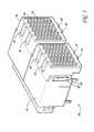
- FIG. 3is a perspective view of the second connector of FIGS. 1 and 2;
- FIG. 4is a perspective view of part of the second connector of FIG. 3;
- FIG. 5is a perspective view of part of the second connector of FIG. 3;
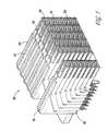
- FIG. 6is a perspective view of a plurality of modules of the second connector of FIG. 3;
- FIG. 7is a perspective view of a pin according to a preferred embodiment of this invention and a receptacle contact of the second connector of FIG. 3;
- FIG. 8is a second perspective view of the pin and receptacle contact of FIG. 7;
- FIG. 9is a perspective view of the first connector of FIG. 1 and the contact pins according to a preferred embodiment of this invention.
- FIG. 10is a perspective view of a pin according to a preferred embodiment of this invention.
- FIG. 11is an end view of the contact pin of FIG. 10.
- FIG. 11 ais an end view of the contact pin of FIG. 10 being inserted between mating contacts;
- FIG. 12is a perspective view of the contact pin of FIG. 10 being mated to a ground contact of the second connector;
- FIG. 13is a perspective view of a second preferred embodiment of a pin of this invention.
- FIGS. 1 and 2An embodiment of a connector system 10 of this invention is depicted in FIGS. 1 and 2.
- the connector system 10preferably includes a first connector 12 and a second connector 14 .
- the first connector 12is preferably a pin connector
- the second connector 14is preferably a receptacle connector.
- FIG. 1depicts the pin connector 12 and the receptacle connector 14 mated
- FIG. 2depicts the pin connector 12 and the receptacle connector prior to being mated.
- the connector system 10may have a variety of applications, one such applications is as a high speed transmission connector system.
- the receptacle connector 14may include a front housing 16 and a rear housing 18 . Both the front and the rear receptacle housings 16 , 18 are preferably a molded polymer and even more preferably a high temperature thermoplastic. FIG. 3 depicts the front housing 16 attached to the rear housing 18 . Although the front and rear housings 16 , 18 can be connected by any suitable means, they are connected in the preferred embodiment with tabs 20 in the front housing 16 which fit into openings 22 in the rear housing 18 . As shown in FIG. 3, the front housing 16 may have a plurality of lead in apertures 24 for receiving pin and signal contacts of the pin connector 12 , which are described below.
- the receptacle connector 14is not new and is described in U.S.
- the receptacle connector 14can, however, be mated with the new pin connector 12 described below to form a new connector system 10 .
- the receptacle connector 14itself is novel in that it includes a new pin design which is described below.
- FIG. 4depicts the receptacle connector 14 with the rear housing 18 removed and a portion of the plurality of modules 26 installed. As explained below, each of the modules 26 has a plurality of receptacle ground and signal contacts.
- FIG. 5depicts the modules 26 of FIG. 4 with the front housing 18 removed
- FIG. 6is an enlarged view of the column of modules 26 on the left hand side of FIG. 5 .
- the column of modules of FIG. 6is used for illustration purposes. It will be appreciated that the columns are all similar.
- the modules 26may each have a spline 27 that can be received in a corresponding slot (not shown) in the rear housing 18 .
- Each of the modules 26has a front housing 28 and a rear housing 30 .
- the front housing 28has openings 30 for receiving signal contacts, as explained in detail in the 926 Patent, of the pin connector 12 as described below.
- the front housing 28provides electrical isolation from the signal contacts from each other and from the ground contacts.
- the signal contactsare not described in more detail here, but they are described in detail in U.S. Pat. No. 6,116,926.
- the ground contacts 32are shown in FIGS. 5-8.
- the ground contacts 32slide into a slot in the modules as described in the 926 patent.
- FIGS. 5 and 6depict the ground contacts 32 connected to the modules 26 so that the ground contacts slide over the front housings 28 .
- the ground contacts 32are shown in detail in FIGS. 7 and 8.
- the ground contact 32can receive a ground pin which is described in more detail below.
- the ground contact 32has shielding tabs 34 and 36 that provide electromagnetic shielding to the electrical ground connection.
- the ground contact 32may further have a terminal 38 for connection to another electrical component.
- the ground contact 32may also have a pair of contact points 40 , 42 .
- One of the contact points 42extends from the shielding tab 36 , and the other contact point 40 is disposed on the cantilever 44 .
- a ground pin of the first connector 10slides between the contact points 40 , 42 to create an electrical connection.
- the first connector 12 of FIG. 1is depicted detached from the second connector 14 in FIG. 2 and by itself in FIG. 9 .
- the first connector 12may be constructed from a polymer and preferably a high temperature thermal plastic.
- the first connector 12 and the second connector 14can be attached in any of a variety of ways.
- the first connector 12has a plurality of slots 45 for receiving tabs 47 of the second connector 14 , which are depicted in FIG. 3 .
- the first and the second connectors 12 , 14can be attached as shown in FIG. 1 .
- Everything that has been described thus far with the exception of the pins 48is prior art to this invention, and the pins 48 which are described in more detail below are the novel part of this invention.
- ground and signal pins 48Disposed within the first connector 12 are a plurality of ground and signal pins 48 .
- the ground and signal pins 48are preferably all the same, and they are either a ground or a signal pin depending upon whether they are mated with a ground contact or a receptacle contact in the second housing 14 .
- the pins 48extend through the first connector 12 so that they extend from two sides of the connector 12 .
- One side of the first connector 12can attach to the second connector as shown in FIG. 1 .
- the opposing sidewhich has extending pins, can attach to another corresponding electrical component (not shown).
- the pins 48can be mounted in any suitable fashion to the first connector 12 .
- the pins 48can be molded into slots (not shown), attached with an adhesive or soldered to the slots.
- FIG. 10A perspective view of one of the pins 48 is shown in FIG. 10 . Although one pin 48 is described, it will be appreciated that all of the pins 48 of the first connector 12 are similar.
- the pins 48may be stamped from phosphor bronze, beryllium copper or any suitable material. Other manufacturing processes can be used as well.
- the pin 48preferably has a stem 50 and two tips 52 , 54 .
- the stem 50is preferably rectangular or square in cross-section, but it need not be and any suitable shape can be used. Coupled to each end of the stem 50 is a tip 52 , 54 .
- the tip 52has four sides two 55 , 56 of which are shown in FIG. 10 . Although only two sides 55 , 56 are shown in FIG. 10, it will be appreciated that the two other pin sides are similar to one of the pin sides 55 , 56 . For example, if side 55 is considered the top in FIG. 10, the bottom side of the pin is similar in construction to the top side 55 . Moreover, the other side of the pin is similar in construction to the side 56 .
- the side 55is relatively flat and is disposed substantially parallel to the stem 50 , as shown in FIG. 10 . This will also be understood with reference to FIG. 11, which is an end view of the tip 52 .
- the side 56preferable has two sections 58 , 60 .
- the first section 58is disposed substantially parallel to the stem 50 .
- the second sectionis disposed at an angle to the first section 58 and extends from the first section 56 to the end 62 of the tip 52 , as shown in FIGS. 10 and 11.
- FIG. 11also illustrates the angled section 60 of the side which is similar to the side 56 .
- the end 62 of the tip 52is relatively flat and may be disposed substantially perpendicular to the stem 48 .
- Two angled portions 64 , 66may connect the end 80 to the top and bottom sides, as shown in FIGS. 10 and 11.
- FIGS. 7 and 8depict a pin 48 aligned with a ground contact 32
- FIG. 12illustrates a pin 48 being mated to a ground contact 32
- the end 62 of the tip 52is inserted between the contact points 42 , 44 of a ground contact 32 of the connector 14 .
- the angled side sections 62help to align the pin between the contact points of the ground contact 32 as the pin is inserted into the contact.
- the tip top 54 and bottom sectionsdue to their lager size and flat profile ensure that the pin will be aligned and not track to the side.
- the relatively large size of the pin tip 52prevents the contacts 32 from side tracking or from riding on the sides of the pins to the top of the pins. By preventing this side tracking, the insertion forces are reduced, and unnecessary pin wear is prevented. This prevents unnecessary wear of the pin surfaces and premature pin failure.
- the new pin tip 52has an increased profile relative to that of the old pin tip 54 , which may still be used on the opposing end of the pin 48 .
- the increased profile of the pin tip 52is designed such that it will prevent side tracking and also prevent friction forces when inserted into the window of the modules 26 .
- the profiled tipis large enough and profiled to prevent side tracking, and small enough and profiled to prevent friction or rubbing against the walls of the modules 26 .
- FIG. 13depicts a second preferred embodiment of this invention.
- the pin 48has a tip 52 at either end.
- This embodimentis applicable mid-plane applications.
- the first preferred embodiment having only one tip 52is applicable in back plane applications.
Landscapes
- Coupling Device And Connection With Printed Circuit (AREA)
- Details Of Connecting Devices For Male And Female Coupling (AREA)
Abstract
Description
Claims (28)
Priority Applications (1)
| Application Number | Priority Date | Filing Date | Title |
|---|---|---|---|
| US09/921,352US6695627B2 (en) | 2001-08-02 | 2001-08-02 | Profiled header ground pin |
Applications Claiming Priority (1)
| Application Number | Priority Date | Filing Date | Title |
|---|---|---|---|
| US09/921,352US6695627B2 (en) | 2001-08-02 | 2001-08-02 | Profiled header ground pin |
Publications (2)
| Publication Number | Publication Date |
|---|---|
| US20030027442A1 US20030027442A1 (en) | 2003-02-06 |
| US6695627B2true US6695627B2 (en) | 2004-02-24 |
Family
ID=25445314
Family Applications (1)
| Application Number | Title | Priority Date | Filing Date |
|---|---|---|---|
| US09/921,352Expired - LifetimeUS6695627B2 (en) | 2001-08-02 | 2001-08-02 | Profiled header ground pin |
Country Status (1)
| Country | Link |
|---|---|
| US (1) | US6695627B2 (en) |
Cited By (50)
| Publication number | Priority date | Publication date | Assignee | Title |
|---|---|---|---|---|
| US20040161954A1 (en)* | 2001-07-31 | 2004-08-19 | Fci Americas Technology Inc. | Modular mezzanine connector |
| US20040185716A1 (en)* | 2003-03-20 | 2004-09-23 | Takeshi Kimura | Electrical connector assembly |
| US20050048838A1 (en)* | 2003-08-29 | 2005-03-03 | Korsunsky Iosif R. | Electrical connector having circuit board modules positioned between metal stiffener and a housing |
| US20050170700A1 (en)* | 2001-11-14 | 2005-08-04 | Shuey Joseph B. | High speed electrical connector without ground contacts |
| US20050196987A1 (en)* | 2001-11-14 | 2005-09-08 | Shuey Joseph B. | High density, low noise, high speed mezzanine connector |
| US20050277315A1 (en)* | 2004-06-10 | 2005-12-15 | Samtec, Inc. | Array connector having improved electrical characteristics and increased signal pins with decreased ground pins |
| US20050287850A1 (en)* | 2001-11-14 | 2005-12-29 | Minich Steven E | Electrical connectors having differential signal pairs configured to reduce cross-talk on adjacent pairs |
| US20050287849A1 (en)* | 2001-11-14 | 2005-12-29 | Fci Americas Technology, Inc. | Cross talk reduction and impedance matching for high speed electrical connectors |
| US20060019517A1 (en)* | 2001-11-14 | 2006-01-26 | Fci Americas Technology, Inc. | Impedance control in electrical connectors |
| US20060035530A1 (en)* | 2001-11-14 | 2006-02-16 | Fci Americas Technology, Inc. | High speed differential transmission structures without grounds |
| US20060068641A1 (en)* | 2003-09-26 | 2006-03-30 | Hull Gregory A | Impedance mathing interface for electrical connectors |
| US20060228912A1 (en)* | 2005-04-07 | 2006-10-12 | Fci Americas Technology, Inc. | Orthogonal backplane connector |
| US20060245137A1 (en)* | 2005-04-29 | 2006-11-02 | Fci Americas Technology, Inc. | Backplane connectors |
| US20070207632A1 (en)* | 2006-03-03 | 2007-09-06 | Fci Americas Technology, Inc. | Midplane with offset connectors |
| US20070207674A1 (en)* | 2006-03-03 | 2007-09-06 | Fci Americas Technology, Inc. | Broadside-to-edge-coupling connector system |
| US20070207641A1 (en)* | 2006-03-03 | 2007-09-06 | Fci Americas Technology, Inc. | High-density orthogonal connector |
| US20070205774A1 (en)* | 2006-03-03 | 2007-09-06 | Fci Americas Technology, Inc.. | Electrical connectors |
| US20070207675A1 (en)* | 2006-03-03 | 2007-09-06 | Fci Americas Technology, Inc. | Edge and broadside coupled connector |
| US20070296066A1 (en)* | 2006-06-27 | 2007-12-27 | Joseph Blair Shuey | Electrical connector with elongated ground contacts |
| US20080003880A1 (en)* | 2004-09-29 | 2008-01-03 | Fci Americas Technology, Inc. | High speed connectors that minimize signal skew and crosstalk |
| US20080045079A1 (en)* | 2006-08-21 | 2008-02-21 | Minich Steven E | Electrical Connector System With Jogged Contact Tails |
| US7422444B1 (en) | 2007-02-28 | 2008-09-09 | Fci Americas Technology, Inc. | Orthogonal header |
| US7497736B2 (en) | 2006-12-19 | 2009-03-03 | Fci Americas Technology, Inc. | Shieldless, high-speed, low-cross-talk electrical connector |
| US7517250B2 (en) | 2003-09-26 | 2009-04-14 | Fci Americas Technology, Inc. | Impedance mating interface for electrical connectors |
| US20090221165A1 (en)* | 2008-02-29 | 2009-09-03 | Buck Jonathan E | Cross talk reduction for high speed electrical connectors |
| US7708569B2 (en) | 2006-10-30 | 2010-05-04 | Fci Americas Technology, Inc. | Broadside-coupled signal pair configurations for electrical connectors |
| US7713088B2 (en) | 2006-10-05 | 2010-05-11 | Fci | Broadside-coupled signal pair configurations for electrical connectors |
| US20100273354A1 (en)* | 2007-07-13 | 2010-10-28 | Stoner Stuart C | Electrical connector system having a continuous ground at the mating interface thereof |
| US20110021083A1 (en)* | 2009-07-24 | 2011-01-27 | Fci Americas Technology, Inc. | Dual Impedance Electrical Connector |
| US20110097934A1 (en)* | 2009-10-28 | 2011-04-28 | Minich Steven E | Electrical connector having ground plates and ground coupling bar |
| US20110117781A1 (en)* | 2009-11-13 | 2011-05-19 | Stoner Stuart C | Attachment system for electrical connector |
| US20110159744A1 (en)* | 2009-12-30 | 2011-06-30 | Buck Jonathan E | Electrical connector having impedance tuning ribs |
| US8540525B2 (en) | 2008-12-12 | 2013-09-24 | Molex Incorporated | Resonance modifying connector |
| US8545240B2 (en) | 2008-11-14 | 2013-10-01 | Molex Incorporated | Connector with terminals forming differential pairs |
| US8727809B2 (en)* | 2011-09-06 | 2014-05-20 | Samtec, Inc. | Center conductor with surrounding shield and edge card connector with same |
| USD718253S1 (en) | 2012-04-13 | 2014-11-25 | Fci Americas Technology Llc | Electrical cable connector |
| US8905651B2 (en) | 2012-01-31 | 2014-12-09 | Fci | Dismountable optical coupling device |
| USD720698S1 (en) | 2013-03-15 | 2015-01-06 | Fci Americas Technology Llc | Electrical cable connector |
| US8944831B2 (en) | 2012-04-13 | 2015-02-03 | Fci Americas Technology Llc | Electrical connector having ribbed ground plate with engagement members |
| USD727268S1 (en) | 2012-04-13 | 2015-04-21 | Fci Americas Technology Llc | Vertical electrical connector |
| USD727852S1 (en) | 2012-04-13 | 2015-04-28 | Fci Americas Technology Llc | Ground shield for a right angle electrical connector |
| US9048583B2 (en) | 2009-03-19 | 2015-06-02 | Fci Americas Technology Llc | Electrical connector having ribbed ground plate |
| USD733662S1 (en) | 2013-01-25 | 2015-07-07 | Fci Americas Technology Llc | Connector housing for electrical connector |
| US9136634B2 (en) | 2010-09-03 | 2015-09-15 | Fci Americas Technology Llc | Low-cross-talk electrical connector |
| USD746236S1 (en) | 2012-07-11 | 2015-12-29 | Fci Americas Technology Llc | Electrical connector housing |
| US9257778B2 (en) | 2012-04-13 | 2016-02-09 | Fci Americas Technology | High speed electrical connector |
| US9277649B2 (en) | 2009-02-26 | 2016-03-01 | Fci Americas Technology Llc | Cross talk reduction for high-speed electrical connectors |
| US20160359280A1 (en)* | 2015-06-05 | 2016-12-08 | Odu Gmbh & Co. Kg | Plug or socket as a component for an electrical connector and electrical connector |
| US9543703B2 (en) | 2012-07-11 | 2017-01-10 | Fci Americas Technology Llc | Electrical connector with reduced stack height |
| US9843119B1 (en)* | 2016-06-08 | 2017-12-12 | Oupiin Electronic (Kunshan) Co., Ltd | High speed connector assembly, receptacle connector and receptacle terminal |
Families Citing this family (4)
| Publication number | Priority date | Publication date | Assignee | Title |
|---|---|---|---|---|
| DE10310502A1 (en)* | 2003-03-11 | 2004-09-23 | Molex Inc., Lisle | Earthed electrical connector for GHz signal frequency range, has earthing terminal provided with at least 2 mechanically coupled electrical contacts |
| US8007315B2 (en)* | 2009-06-29 | 2011-08-30 | Tyco Electronics Corporation | Electrical connector system having reduced mating forces |
| US8371876B2 (en)* | 2010-02-24 | 2013-02-12 | Tyco Electronics Corporation | Increased density connector system |
| CN114361851B (en)* | 2022-03-17 | 2022-06-14 | 深圳金益成电子科技有限公司 | Modular spliced pin header |
Citations (28)
| Publication number | Priority date | Publication date | Assignee | Title |
|---|---|---|---|---|
| US4601527A (en) | 1985-01-18 | 1986-07-22 | E. I. Du Pont De Nemours And Company | Shielded header and cable assembly |
| US4686607A (en) | 1986-01-08 | 1987-08-11 | Teradyne, Inc. | Daughter board/backplane assembly |
| US4720268A (en) | 1987-03-23 | 1988-01-19 | Industrial Electronic Hardware | Compliant conductive pin |
| US4737116A (en) | 1986-04-21 | 1988-04-12 | Micro Component Technology, Inc. | Impedance matching block |
| US4861132A (en) | 1987-11-23 | 1989-08-29 | Hughes Aircraft Company | Self-aligning precision guide pin |
| US4907988A (en) | 1988-03-15 | 1990-03-13 | Inovan G.m.b.H. & Co. KG, Metalle und Bauelemente | Contact pin |
| US4975084A (en) | 1988-10-17 | 1990-12-04 | Amp Incorporated | Electrical connector system |
| US5116263A (en) | 1988-03-30 | 1992-05-26 | Amp Incorporated | Connector for posted terminals |
| US5174770A (en) | 1990-11-15 | 1992-12-29 | Amp Incorporated | Multicontact connector for signal transmission |
| US5197893A (en) | 1990-03-14 | 1993-03-30 | Burndy Corporation | Connector assembly for printed circuit boards |
| US5310354A (en) | 1992-03-20 | 1994-05-10 | E. I. Du Pont De Nemours And Company | Integral ground terminal and tail shield |
| US5588851A (en) | 1994-03-03 | 1996-12-31 | Framatome Connectors International | Connector for a cable for high frequency signals |
| US5620340A (en) | 1992-12-31 | 1997-04-15 | Berg Technology, Inc. | Connector with improved shielding |
| US5660551A (en)* | 1993-10-20 | 1997-08-26 | Minnesota Mining And Manufacturing Company | High speed transmission line connector |
| US5664968A (en) | 1996-03-29 | 1997-09-09 | The Whitaker Corporation | Connector assembly with shielded modules |
| US5667392A (en) | 1995-03-28 | 1997-09-16 | The Whitaker Corporation | Electrical connector with stabilized contact |
| US5761050A (en) | 1996-08-23 | 1998-06-02 | Cts Corporation | Deformable pin connector for multiple PC boards |
| US5775947A (en) | 1993-07-27 | 1998-07-07 | Japan Aviation Electronics Industry, Limited | Multi-contact connector with cross-talk blocking elements between signal contacts |
| US5813871A (en) | 1996-07-31 | 1998-09-29 | The Whitaker Corporation | High frequency electrical connector |
| US5839925A (en) | 1995-09-29 | 1998-11-24 | The Whitaker Corporation | Electrical receptacle terminals |
| EP0907225A2 (en) | 1997-10-01 | 1999-04-07 | Berg Electronics Manufacturing B.V. | Connector for electrical isolation in a condensed area |
| US6030234A (en) | 1998-01-23 | 2000-02-29 | Molex Incorporated | Terminal pins mounted in flexible substrates |
| US6053751A (en) | 1996-10-10 | 2000-04-25 | Thomas & Betts Corporation | Controlled impedance, high density electrical connector |
| US6098281A (en) | 1996-11-06 | 2000-08-08 | Weidmuller Interface Gmbh & Co. | Electrical pins and method for their insertion into apertures of a circuit board |
| US6116926A (en) | 1999-04-21 | 2000-09-12 | Berg Technology, Inc. | Connector for electrical isolation in a condensed area |
| US6129555A (en) | 1998-08-17 | 2000-10-10 | Fujitsu Takamisawa Component Limited | Jack connector, plug connector and connector assembly |
| US6159048A (en)* | 1998-06-30 | 2000-12-12 | Framatome Connectors International | Connector for high frequency signals |
| US6166615A (en) | 1998-09-16 | 2000-12-26 | Raytheon Company | Blind mate non-crimp pin RF connector |
- 2001
- 2001-08-02USUS09/921,352patent/US6695627B2/ennot_activeExpired - Lifetime
Patent Citations (28)
| Publication number | Priority date | Publication date | Assignee | Title |
|---|---|---|---|---|
| US4601527A (en) | 1985-01-18 | 1986-07-22 | E. I. Du Pont De Nemours And Company | Shielded header and cable assembly |
| US4686607A (en) | 1986-01-08 | 1987-08-11 | Teradyne, Inc. | Daughter board/backplane assembly |
| US4737116A (en) | 1986-04-21 | 1988-04-12 | Micro Component Technology, Inc. | Impedance matching block |
| US4720268A (en) | 1987-03-23 | 1988-01-19 | Industrial Electronic Hardware | Compliant conductive pin |
| US4861132A (en) | 1987-11-23 | 1989-08-29 | Hughes Aircraft Company | Self-aligning precision guide pin |
| US4907988A (en) | 1988-03-15 | 1990-03-13 | Inovan G.m.b.H. & Co. KG, Metalle und Bauelemente | Contact pin |
| US5116263A (en) | 1988-03-30 | 1992-05-26 | Amp Incorporated | Connector for posted terminals |
| US4975084A (en) | 1988-10-17 | 1990-12-04 | Amp Incorporated | Electrical connector system |
| US5197893A (en) | 1990-03-14 | 1993-03-30 | Burndy Corporation | Connector assembly for printed circuit boards |
| US5174770A (en) | 1990-11-15 | 1992-12-29 | Amp Incorporated | Multicontact connector for signal transmission |
| US5310354A (en) | 1992-03-20 | 1994-05-10 | E. I. Du Pont De Nemours And Company | Integral ground terminal and tail shield |
| US5620340A (en) | 1992-12-31 | 1997-04-15 | Berg Technology, Inc. | Connector with improved shielding |
| US5775947A (en) | 1993-07-27 | 1998-07-07 | Japan Aviation Electronics Industry, Limited | Multi-contact connector with cross-talk blocking elements between signal contacts |
| US5660551A (en)* | 1993-10-20 | 1997-08-26 | Minnesota Mining And Manufacturing Company | High speed transmission line connector |
| US5588851A (en) | 1994-03-03 | 1996-12-31 | Framatome Connectors International | Connector for a cable for high frequency signals |
| US5667392A (en) | 1995-03-28 | 1997-09-16 | The Whitaker Corporation | Electrical connector with stabilized contact |
| US5839925A (en) | 1995-09-29 | 1998-11-24 | The Whitaker Corporation | Electrical receptacle terminals |
| US5664968A (en) | 1996-03-29 | 1997-09-09 | The Whitaker Corporation | Connector assembly with shielded modules |
| US5813871A (en) | 1996-07-31 | 1998-09-29 | The Whitaker Corporation | High frequency electrical connector |
| US5761050A (en) | 1996-08-23 | 1998-06-02 | Cts Corporation | Deformable pin connector for multiple PC boards |
| US6053751A (en) | 1996-10-10 | 2000-04-25 | Thomas & Betts Corporation | Controlled impedance, high density electrical connector |
| US6098281A (en) | 1996-11-06 | 2000-08-08 | Weidmuller Interface Gmbh & Co. | Electrical pins and method for their insertion into apertures of a circuit board |
| EP0907225A2 (en) | 1997-10-01 | 1999-04-07 | Berg Electronics Manufacturing B.V. | Connector for electrical isolation in a condensed area |
| US6030234A (en) | 1998-01-23 | 2000-02-29 | Molex Incorporated | Terminal pins mounted in flexible substrates |
| US6159048A (en)* | 1998-06-30 | 2000-12-12 | Framatome Connectors International | Connector for high frequency signals |
| US6129555A (en) | 1998-08-17 | 2000-10-10 | Fujitsu Takamisawa Component Limited | Jack connector, plug connector and connector assembly |
| US6166615A (en) | 1998-09-16 | 2000-12-26 | Raytheon Company | Blind mate non-crimp pin RF connector |
| US6116926A (en) | 1999-04-21 | 2000-09-12 | Berg Technology, Inc. | Connector for electrical isolation in a condensed area |
Non-Patent Citations (1)
| Title |
|---|
| Fusi, M.A. "Differential Signal Transmission Through High Speed Interconnects", Publication Date Unknown, 73-78. |
Cited By (118)
| Publication number | Priority date | Publication date | Assignee | Title |
|---|---|---|---|---|
| US20040161954A1 (en)* | 2001-07-31 | 2004-08-19 | Fci Americas Technology Inc. | Modular mezzanine connector |
| US7429176B2 (en) | 2001-07-31 | 2008-09-30 | Fci Americas Technology, Inc. | Modular mezzanine connector |
| US20080214029A1 (en)* | 2001-11-14 | 2008-09-04 | Lemke Timothy A | Shieldless, High-Speed Electrical Connectors |
| US20050287849A1 (en)* | 2001-11-14 | 2005-12-29 | Fci Americas Technology, Inc. | Cross talk reduction and impedance matching for high speed electrical connectors |
| US7442054B2 (en) | 2001-11-14 | 2008-10-28 | Fci Americas Technology, Inc. | Electrical connectors having differential signal pairs configured to reduce cross-talk on adjacent pairs |
| US20050170700A1 (en)* | 2001-11-14 | 2005-08-04 | Shuey Joseph B. | High speed electrical connector without ground contacts |
| US20050196987A1 (en)* | 2001-11-14 | 2005-09-08 | Shuey Joseph B. | High density, low noise, high speed mezzanine connector |
| US20080248693A1 (en)* | 2001-11-14 | 2008-10-09 | Fci Americas Technology, Inc. | Shieldless, high-speed electrical connectors |
| US20050287850A1 (en)* | 2001-11-14 | 2005-12-29 | Minich Steven E | Electrical connectors having differential signal pairs configured to reduce cross-talk on adjacent pairs |
| US7390200B2 (en) | 2001-11-14 | 2008-06-24 | Fci Americas Technology, Inc. | High speed differential transmission structures without grounds |
| US20060019517A1 (en)* | 2001-11-14 | 2006-01-26 | Fci Americas Technology, Inc. | Impedance control in electrical connectors |
| US20060035530A1 (en)* | 2001-11-14 | 2006-02-16 | Fci Americas Technology, Inc. | High speed differential transmission structures without grounds |
| US20060063404A1 (en)* | 2001-11-14 | 2006-03-23 | Fci Americas Technology, Inc. | Electrical connectors having contacts that may be selectively designated as either signal or ground contacts |
| US7390218B2 (en) | 2001-11-14 | 2008-06-24 | Fci Americas Technology, Inc. | Shieldless, high-speed electrical connectors |
| US7114964B2 (en) | 2001-11-14 | 2006-10-03 | Fci Americas Technology, Inc. | Cross talk reduction and impedance matching for high speed electrical connectors |
| US7118391B2 (en) | 2001-11-14 | 2006-10-10 | Fci Americas Technology, Inc. | Electrical connectors having contacts that may be selectively designated as either signal or ground contacts |
| US7331800B2 (en) | 2001-11-14 | 2008-02-19 | Fci Americas Technology, Inc. | Shieldless, high-speed electrical connectors |
| US20060234532A1 (en)* | 2001-11-14 | 2006-10-19 | Fci Americas Technology, Inc. | Shieldless, high-speed electrical connectors |
| US20060246756A1 (en)* | 2001-11-14 | 2006-11-02 | Fci Americas Technology, Inc. | Shieldless, high-speed electrical connectors |
| US7309239B2 (en) | 2001-11-14 | 2007-12-18 | Fci Americas Technology, Inc. | High-density, low-noise, high-speed mezzanine connector |
| US7467955B2 (en) | 2001-11-14 | 2008-12-23 | Fci Americas Technology, Inc. | Impedance control in electrical connectors |
| US7182643B2 (en) | 2001-11-14 | 2007-02-27 | Fci Americas Technology, Inc. | Shieldless, high-speed electrical connectors |
| US20070059952A1 (en)* | 2001-11-14 | 2007-03-15 | Fci Americas Technology, Inc. | Impedance control in electrical connectors |
| US20070099464A1 (en)* | 2001-11-14 | 2007-05-03 | Winings Clifford L | Shieldless, High-Speed Electrical Connectors |
| US7229318B2 (en) | 2001-11-14 | 2007-06-12 | Fci Americas Technology, Inc. | Shieldless, high-speed electrical connectors |
| US20070190825A1 (en)* | 2001-11-14 | 2007-08-16 | Fci Americas Technology, Inc. | High-density, low-noise, high-speed mezzanine connector |
| US6866549B2 (en)* | 2003-03-20 | 2005-03-15 | Tyco Electronics Amp K.K. | Electrical connector assembly |
| US20040185716A1 (en)* | 2003-03-20 | 2004-09-23 | Takeshi Kimura | Electrical connector assembly |
| US20050048838A1 (en)* | 2003-08-29 | 2005-03-03 | Korsunsky Iosif R. | Electrical connector having circuit board modules positioned between metal stiffener and a housing |
| US6884117B2 (en)* | 2003-08-29 | 2005-04-26 | Hon Hai Precision Ind. Co., Ltd. | Electrical connector having circuit board modules positioned between metal stiffener and a housing |
| US7837504B2 (en) | 2003-09-26 | 2010-11-23 | Fci Americas Technology, Inc. | Impedance mating interface for electrical connectors |
| US20060068641A1 (en)* | 2003-09-26 | 2006-03-30 | Hull Gregory A | Impedance mathing interface for electrical connectors |
| US7524209B2 (en) | 2003-09-26 | 2009-04-28 | Fci Americas Technology, Inc. | Impedance mating interface for electrical connectors |
| US7517250B2 (en) | 2003-09-26 | 2009-04-14 | Fci Americas Technology, Inc. | Impedance mating interface for electrical connectors |
| US20050277315A1 (en)* | 2004-06-10 | 2005-12-15 | Samtec, Inc. | Array connector having improved electrical characteristics and increased signal pins with decreased ground pins |
| US7137832B2 (en)* | 2004-06-10 | 2006-11-21 | Samtec Incorporated | Array connector having improved electrical characteristics and increased signal pins with decreased ground pins |
| US7497735B2 (en) | 2004-09-29 | 2009-03-03 | Fci Americas Technology, Inc. | High speed connectors that minimize signal skew and crosstalk |
| US20080003880A1 (en)* | 2004-09-29 | 2008-01-03 | Fci Americas Technology, Inc. | High speed connectors that minimize signal skew and crosstalk |
| US20060228912A1 (en)* | 2005-04-07 | 2006-10-12 | Fci Americas Technology, Inc. | Orthogonal backplane connector |
| US20060245137A1 (en)* | 2005-04-29 | 2006-11-02 | Fci Americas Technology, Inc. | Backplane connectors |
| US20070207641A1 (en)* | 2006-03-03 | 2007-09-06 | Fci Americas Technology, Inc. | High-density orthogonal connector |
| US7344391B2 (en) | 2006-03-03 | 2008-03-18 | Fci Americas Technology, Inc. | Edge and broadside coupled connector |
| US7407413B2 (en) | 2006-03-03 | 2008-08-05 | Fci Americas Technology, Inc. | Broadside-to-edge-coupling connector system |
| US20070207632A1 (en)* | 2006-03-03 | 2007-09-06 | Fci Americas Technology, Inc. | Midplane with offset connectors |
| US7431616B2 (en) | 2006-03-03 | 2008-10-07 | Fci Americas Technology, Inc. | Orthogonal electrical connectors |
| US7331830B2 (en) | 2006-03-03 | 2008-02-19 | Fci Americas Technology, Inc. | High-density orthogonal connector |
| US20070207674A1 (en)* | 2006-03-03 | 2007-09-06 | Fci Americas Technology, Inc. | Broadside-to-edge-coupling connector system |
| US20070205774A1 (en)* | 2006-03-03 | 2007-09-06 | Fci Americas Technology, Inc.. | Electrical connectors |
| US20070207675A1 (en)* | 2006-03-03 | 2007-09-06 | Fci Americas Technology, Inc. | Edge and broadside coupled connector |
| US20090149041A1 (en)* | 2006-03-24 | 2009-06-11 | Morlion Danny L C | Orthogonal Backplane Connector |
| US20070296066A1 (en)* | 2006-06-27 | 2007-12-27 | Joseph Blair Shuey | Electrical connector with elongated ground contacts |
| US7462924B2 (en) | 2006-06-27 | 2008-12-09 | Fci Americas Technology, Inc. | Electrical connector with elongated ground contacts |
| US7500871B2 (en) | 2006-08-21 | 2009-03-10 | Fci Americas Technology, Inc. | Electrical connector system with jogged contact tails |
| US7837505B2 (en) | 2006-08-21 | 2010-11-23 | Fci Americas Technology Llc | Electrical connector system with jogged contact tails |
| US20080045079A1 (en)* | 2006-08-21 | 2008-02-21 | Minich Steven E | Electrical Connector System With Jogged Contact Tails |
| US20090124101A1 (en)* | 2006-08-21 | 2009-05-14 | Minich Steven E | Electrical connector system with jogged contact tails |
| US7713088B2 (en) | 2006-10-05 | 2010-05-11 | Fci | Broadside-coupled signal pair configurations for electrical connectors |
| US7708569B2 (en) | 2006-10-30 | 2010-05-04 | Fci Americas Technology, Inc. | Broadside-coupled signal pair configurations for electrical connectors |
| US8382521B2 (en) | 2006-12-19 | 2013-02-26 | Fci Americas Technology Llc | Shieldless, high-speed, low-cross-talk electrical connector |
| US8096832B2 (en) | 2006-12-19 | 2012-01-17 | Fci Americas Technology Llc | Shieldless, high-speed, low-cross-talk electrical connector |
| US7762843B2 (en) | 2006-12-19 | 2010-07-27 | Fci Americas Technology, Inc. | Shieldless, high-speed, low-cross-talk electrical connector |
| US8678860B2 (en) | 2006-12-19 | 2014-03-25 | Fci Americas Technology Llc | Shieldless, high-speed, low-cross-talk electrical connector |
| US20100291806A1 (en)* | 2006-12-19 | 2010-11-18 | Minich Steven E | Shieldless, High-Speed, Low-Cross-Talk Electrical Connector |
| US7497736B2 (en) | 2006-12-19 | 2009-03-03 | Fci Americas Technology, Inc. | Shieldless, high-speed, low-cross-talk electrical connector |
| US20110113625A1 (en)* | 2007-02-28 | 2011-05-19 | Fci Americas Technology, Inc. | Orthogonal header |
| US20100048067A1 (en)* | 2007-02-28 | 2010-02-25 | Johnescu Douglas M | Orthogonal header |
| US7422444B1 (en) | 2007-02-28 | 2008-09-09 | Fci Americas Technology, Inc. | Orthogonal header |
| US8057267B2 (en) | 2007-02-28 | 2011-11-15 | Fci Americas Technology Llc | Orthogonal header |
| US7967647B2 (en)* | 2007-02-28 | 2011-06-28 | Fci Americas Technology Llc | Orthogonal header |
| US20100273354A1 (en)* | 2007-07-13 | 2010-10-28 | Stoner Stuart C | Electrical connector system having a continuous ground at the mating interface thereof |
| US8137119B2 (en) | 2007-07-13 | 2012-03-20 | Fci Americas Technology Llc | Electrical connector system having a continuous ground at the mating interface thereof |
| US8764464B2 (en) | 2008-02-29 | 2014-07-01 | Fci Americas Technology Llc | Cross talk reduction for high speed electrical connectors |
| US20090221165A1 (en)* | 2008-02-29 | 2009-09-03 | Buck Jonathan E | Cross talk reduction for high speed electrical connectors |
| US8545240B2 (en) | 2008-11-14 | 2013-10-01 | Molex Incorporated | Connector with terminals forming differential pairs |
| US8540525B2 (en) | 2008-12-12 | 2013-09-24 | Molex Incorporated | Resonance modifying connector |
| US8992237B2 (en) | 2008-12-12 | 2015-03-31 | Molex Incorporated | Resonance modifying connector |
| US8651881B2 (en) | 2008-12-12 | 2014-02-18 | Molex Incorporated | Resonance modifying connector |
| US9277649B2 (en) | 2009-02-26 | 2016-03-01 | Fci Americas Technology Llc | Cross talk reduction for high-speed electrical connectors |
| US10720721B2 (en) | 2009-03-19 | 2020-07-21 | Fci Usa Llc | Electrical connector having ribbed ground plate |
| US9048583B2 (en) | 2009-03-19 | 2015-06-02 | Fci Americas Technology Llc | Electrical connector having ribbed ground plate |
| US9461410B2 (en) | 2009-03-19 | 2016-10-04 | Fci Americas Technology Llc | Electrical connector having ribbed ground plate |
| US10096921B2 (en) | 2009-03-19 | 2018-10-09 | Fci Usa Llc | Electrical connector having ribbed ground plate |
| US8608510B2 (en) | 2009-07-24 | 2013-12-17 | Fci Americas Technology Llc | Dual impedance electrical connector |
| US20110021083A1 (en)* | 2009-07-24 | 2011-01-27 | Fci Americas Technology, Inc. | Dual Impedance Electrical Connector |
| US8267721B2 (en) | 2009-10-28 | 2012-09-18 | Fci Americas Technology Llc | Electrical connector having ground plates and ground coupling bar |
| US20110097934A1 (en)* | 2009-10-28 | 2011-04-28 | Minich Steven E | Electrical connector having ground plates and ground coupling bar |
| US20110117781A1 (en)* | 2009-11-13 | 2011-05-19 | Stoner Stuart C | Attachment system for electrical connector |
| US8616919B2 (en) | 2009-11-13 | 2013-12-31 | Fci Americas Technology Llc | Attachment system for electrical connector |
| US8715003B2 (en) | 2009-12-30 | 2014-05-06 | Fci Americas Technology Llc | Electrical connector having impedance tuning ribs |
| US20110159744A1 (en)* | 2009-12-30 | 2011-06-30 | Buck Jonathan E | Electrical connector having impedance tuning ribs |
| US9136634B2 (en) | 2010-09-03 | 2015-09-15 | Fci Americas Technology Llc | Low-cross-talk electrical connector |
| US20140220820A1 (en)* | 2011-09-06 | 2014-08-07 | Samtec, Inc. | Center conductor with surrounding shield and edge card connector with same |
| US8727809B2 (en)* | 2011-09-06 | 2014-05-20 | Samtec, Inc. | Center conductor with surrounding shield and edge card connector with same |
| US9130313B2 (en)* | 2011-09-06 | 2015-09-08 | Samtec, Inc. | Center conductor with surrounding shield and edge card connector with same |
| US8905651B2 (en) | 2012-01-31 | 2014-12-09 | Fci | Dismountable optical coupling device |
| US8944831B2 (en) | 2012-04-13 | 2015-02-03 | Fci Americas Technology Llc | Electrical connector having ribbed ground plate with engagement members |
| USD727268S1 (en) | 2012-04-13 | 2015-04-21 | Fci Americas Technology Llc | Vertical electrical connector |
| USD718253S1 (en) | 2012-04-13 | 2014-11-25 | Fci Americas Technology Llc | Electrical cable connector |
| USD816044S1 (en) | 2012-04-13 | 2018-04-24 | Fci Americas Technology Llc | Electrical cable connector |
| USD748063S1 (en) | 2012-04-13 | 2016-01-26 | Fci Americas Technology Llc | Electrical ground shield |
| US9257778B2 (en) | 2012-04-13 | 2016-02-09 | Fci Americas Technology | High speed electrical connector |
| USD750025S1 (en) | 2012-04-13 | 2016-02-23 | Fci Americas Technology Llc | Vertical electrical connector |
| USD750030S1 (en) | 2012-04-13 | 2016-02-23 | Fci Americas Technology Llc | Electrical cable connector |
| USD727852S1 (en) | 2012-04-13 | 2015-04-28 | Fci Americas Technology Llc | Ground shield for a right angle electrical connector |
| US9831605B2 (en) | 2012-04-13 | 2017-11-28 | Fci Americas Technology Llc | High speed electrical connector |
| USD790471S1 (en) | 2012-04-13 | 2017-06-27 | Fci Americas Technology Llc | Vertical electrical connector |
| US9543703B2 (en) | 2012-07-11 | 2017-01-10 | Fci Americas Technology Llc | Electrical connector with reduced stack height |
| USD751507S1 (en) | 2012-07-11 | 2016-03-15 | Fci Americas Technology Llc | Electrical connector |
| US9871323B2 (en) | 2012-07-11 | 2018-01-16 | Fci Americas Technology Llc | Electrical connector with reduced stack height |
| USD746236S1 (en) | 2012-07-11 | 2015-12-29 | Fci Americas Technology Llc | Electrical connector housing |
| USD733662S1 (en) | 2013-01-25 | 2015-07-07 | Fci Americas Technology Llc | Connector housing for electrical connector |
| USD772168S1 (en) | 2013-01-25 | 2016-11-22 | Fci Americas Technology Llc | Connector housing for electrical connector |
| USD766832S1 (en) | 2013-01-25 | 2016-09-20 | Fci Americas Technology Llc | Electrical connector |
| USD745852S1 (en) | 2013-01-25 | 2015-12-22 | Fci Americas Technology Llc | Electrical connector |
| USD720698S1 (en) | 2013-03-15 | 2015-01-06 | Fci Americas Technology Llc | Electrical cable connector |
| US20160359280A1 (en)* | 2015-06-05 | 2016-12-08 | Odu Gmbh & Co. Kg | Plug or socket as a component for an electrical connector and electrical connector |
| US9972948B2 (en)* | 2015-06-05 | 2018-05-15 | Odu Gmbh & Co. Kg | Plug or socket as a component for an electrical connector and electrical connector |
| US9843119B1 (en)* | 2016-06-08 | 2017-12-12 | Oupiin Electronic (Kunshan) Co., Ltd | High speed connector assembly, receptacle connector and receptacle terminal |
Also Published As
| Publication number | Publication date |
|---|---|
| US20030027442A1 (en) | 2003-02-06 |
Similar Documents
| Publication | Publication Date | Title |
|---|---|---|
| US6695627B2 (en) | Profiled header ground pin | |
| US11450979B2 (en) | Receptacle connector with alignment features | |
| US10320102B2 (en) | Receptacle connector with contact assembly | |
| EP0795929B1 (en) | Electric connector assembly with improved retention characteristics | |
| KR100666067B1 (en) | Electrical contact with orthogonal contact arm and offset contact area | |
| JP4881461B2 (en) | High speed, high density electrical connector | |
| US7232344B1 (en) | High speed, card edge connector | |
| US7059919B2 (en) | Power connector | |
| EP0702429B1 (en) | Polarizing system for a blind mating electrical connector assembly | |
| US6244910B1 (en) | Electrical box contact with stress limitation | |
| US20040058568A1 (en) | Electrical connector assembly with complementary recess and projection interengagement | |
| US20050266728A1 (en) | Electrical connector with load bearing features | |
| US6709298B2 (en) | Insulator coring and contact configuration to prevent pin stubbing in the throat of tuning fork socket connector contacts | |
| US6132258A (en) | Board to board electrical connector | |
| US6109981A (en) | Socket contact | |
| US6511352B2 (en) | Connector connection structure | |
| US20250192466A1 (en) | Reliable hybrid electrical connector | |
| US20100227482A1 (en) | Mechanically supported contact and electrical connector utilizing the same | |
| EP1401055A1 (en) | Matable electrical connectors having signal and power capabilities |
Legal Events
| Date | Code | Title | Description |
|---|---|---|---|
| AS | Assignment | Owner name:FCI AMERICAS TECHNOLOGY, INC., NEVADA Free format text:ASSIGNMENT OF ASSIGNORS INTEREST;ASSIGNORS:ORTEGA, JOSE L.;OLSON, STANLEY W.;REEL/FRAME:012281/0347 Effective date:20010928 | |
| STCF | Information on status: patent grant | Free format text:PATENTED CASE | |
| AS | Assignment | Owner name:BANC OF AMERICA SECURITIES LIMITED, AS SECURITY AG Free format text:SECURITY AGREEMENT;ASSIGNOR:FCI AMERICAS TECHNOLOGY, INC.;REEL/FRAME:017400/0192 Effective date:20060331 | |
| FPAY | Fee payment | Year of fee payment:4 | |
| AS | Assignment | Owner name:FCI AMERICAS TECHNOLOGY LLC, NEVADA Free format text:CONVERSION TO LLC;ASSIGNOR:FCI AMERICAS TECHNOLOGY, INC.;REEL/FRAME:025957/0432 Effective date:20090930 | |
| FPAY | Fee payment | Year of fee payment:8 | |
| AS | Assignment | Owner name:FCI AMERICAS TECHNOLOGY LLC (F/K/A FCI AMERICAS TE Free format text:RELEASE OF PATENT SECURITY INTEREST AT REEL/FRAME NO. 17400/0192;ASSIGNOR:BANC OF AMERICA SECURITIES LIMITED;REEL/FRAME:029377/0632 Effective date:20121026 | |
| FPAY | Fee payment | Year of fee payment:12 |