US6695623B2 - Enhanced electrical/mechanical connection for electronic devices - Google Patents
Enhanced electrical/mechanical connection for electronic devicesDownload PDFInfo
- Publication number
- US6695623B2 US6695623B2US09/871,554US87155401AUS6695623B2US 6695623 B2US6695623 B2US 6695623B2US 87155401 AUS87155401 AUS 87155401AUS 6695623 B2US6695623 B2US 6695623B2
- Authority
- US
- United States
- Prior art keywords
- contacts
- conductor
- interposer
- array
- conductors
- Prior art date
- Legal status (The legal status is an assumption and is not a legal conclusion. Google has not performed a legal analysis and makes no representation as to the accuracy of the status listed.)
- Expired - Fee Related
Links
- 239000004020conductorSubstances0.000claimsabstractdescription141
- 239000000853adhesiveSubstances0.000claimsabstractdescription46
- 230000001070adhesive effectEffects0.000claimsabstractdescription46
- 238000000034methodMethods0.000claimsabstractdescription31
- 238000003491arrayMethods0.000claimsabstractdescription14
- 238000001816coolingMethods0.000claimsabstractdescription12
- 238000010438heat treatmentMethods0.000claimsabstractdescription10
- 229910000679solderInorganic materials0.000claimsdescription68
- 239000000758substrateSubstances0.000claimsdescription21
- KDLHZDBZIXYQEI-UHFFFAOYSA-NPalladiumChemical compound[Pd]KDLHZDBZIXYQEI-UHFFFAOYSA-N0.000claimsdescription20
- 229910052763palladiumInorganic materials0.000claimsdescription10
- 238000007747platingMethods0.000claimsdescription7
- PCHJSUWPFVWCPO-UHFFFAOYSA-NgoldChemical compound[Au]PCHJSUWPFVWCPO-UHFFFAOYSA-N0.000claimsdescription6
- 229910052737goldInorganic materials0.000claimsdescription6
- 239000010931goldSubstances0.000claimsdescription6
- 229910000510noble metalInorganic materials0.000claimsdescription6
- 229920001169thermoplasticPolymers0.000claimsdescription6
- 239000004416thermosoftening plasticSubstances0.000claimsdescription6
- 229910000990Ni alloyInorganic materials0.000claimsdescription5
- BQCADISMDOOEFD-UHFFFAOYSA-NSilverChemical compound[Ag]BQCADISMDOOEFD-UHFFFAOYSA-N0.000claimsdescription5
- 230000008569processEffects0.000claimsdescription5
- 229910052709silverInorganic materials0.000claimsdescription5
- 239000004332silverSubstances0.000claimsdescription5
- 238000000151depositionMethods0.000claimsdescription4
- 239000007788liquidSubstances0.000claimsdescription4
- 239000002904solventSubstances0.000claimsdescription4
- 238000005530etchingMethods0.000claimsdescription2
- 238000010009beatingMethods0.000claims1
- 239000011248coating agentSubstances0.000claims1
- 238000000576coating methodMethods0.000claims1
- 229920006332epoxy adhesivePolymers0.000claims1
- QHZSDTDMQZPUKC-UHFFFAOYSA-N3,5-dichlorobiphenylChemical compoundClC1=CC(Cl)=CC(C=2C=CC=CC=2)=C1QHZSDTDMQZPUKC-UHFFFAOYSA-N0.000description8
- 239000000919ceramicSubstances0.000description5
- 238000006073displacement reactionMethods0.000description5
- 239000003822epoxy resinSubstances0.000description5
- 229920000647polyepoxidePolymers0.000description5
- 230000008901benefitEffects0.000description4
- 239000004744fabricSubstances0.000description4
- 239000000835fiberSubstances0.000description4
- 239000000463materialSubstances0.000description4
- 230000035882stressEffects0.000description4
- IYZWUWBAFUBNCH-UHFFFAOYSA-N2,6-dichlorobiphenylChemical compoundClC1=CC=CC(Cl)=C1C1=CC=CC=C1IYZWUWBAFUBNCH-UHFFFAOYSA-N0.000description3
- 230000007717exclusionEffects0.000description3
- 230000007935neutral effectEffects0.000description3
- 239000010970precious metalSubstances0.000description3
- 230000004044responseEffects0.000description3
- PXHVJJICTQNCMI-UHFFFAOYSA-NNickelChemical compound[Ni]PXHVJJICTQNCMI-UHFFFAOYSA-N0.000description2
- 230000008602contractionEffects0.000description2
- 239000011521glassSubstances0.000description2
- 238000004519manufacturing processMethods0.000description2
- 238000005259measurementMethods0.000description2
- 230000007246mechanismEffects0.000description2
- 229910052751metalInorganic materials0.000description2
- 239000002184metalSubstances0.000description2
- 239000000523sampleSubstances0.000description2
- 230000007480spreadingEffects0.000description2
- 238000003892spreadingMethods0.000description2
- RYGMFSIKBFXOCR-UHFFFAOYSA-NCopperChemical compound[Cu]RYGMFSIKBFXOCR-UHFFFAOYSA-N0.000description1
- 229920000271Kevlar®Polymers0.000description1
- ATJFFYVFTNAWJD-UHFFFAOYSA-NTinChemical compound[Sn]ATJFFYVFTNAWJD-UHFFFAOYSA-N0.000description1
- 229910052782aluminiumInorganic materials0.000description1
- XAGFODPZIPBFFR-UHFFFAOYSA-NaluminiumChemical compound[Al]XAGFODPZIPBFFR-UHFFFAOYSA-N0.000description1
- 229910010293ceramic materialInorganic materials0.000description1
- 239000002131composite materialSubstances0.000description1
- 150000001875compoundsChemical class0.000description1
- 238000011109contaminationMethods0.000description1
- 229910052802copperInorganic materials0.000description1
- 239000010949copperSubstances0.000description1
- 230000008021depositionEffects0.000description1
- 230000005489elastic deformationEffects0.000description1
- 238000005516engineering processMethods0.000description1
- 230000006353environmental stressEffects0.000description1
- 230000006870functionEffects0.000description1
- 238000003384imaging methodMethods0.000description1
- 239000012212insulatorSubstances0.000description1
- 238000005304joiningMethods0.000description1
- 239000004761kevlarSubstances0.000description1
- 150000002739metalsChemical class0.000description1
- 238000004377microelectronicMethods0.000description1
- 229910052759nickelInorganic materials0.000description1
- 238000002407reformingMethods0.000description1
- 230000035939shockEffects0.000description1
- 238000005382thermal cyclingMethods0.000description1
- 238000005050thermomechanical fatigueMethods0.000description1
- 229910052718tinInorganic materials0.000description1
- 239000011135tinSubstances0.000description1
Images

Classifications
- H—ELECTRICITY
- H01—ELECTRIC ELEMENTS
- H01R—ELECTRICALLY-CONDUCTIVE CONNECTIONS; STRUCTURAL ASSOCIATIONS OF A PLURALITY OF MUTUALLY-INSULATED ELECTRICAL CONNECTING ELEMENTS; COUPLING DEVICES; CURRENT COLLECTORS
- H01R12/00—Structural associations of a plurality of mutually-insulated electrical connecting elements, specially adapted for printed circuits, e.g. printed circuit boards [PCB], flat or ribbon cables, or like generally planar structures, e.g. terminal strips, terminal blocks; Coupling devices specially adapted for printed circuits, flat or ribbon cables, or like generally planar structures; Terminals specially adapted for contact with, or insertion into, printed circuits, flat or ribbon cables, or like generally planar structures
- H01R12/50—Fixed connections
- H01R12/51—Fixed connections for rigid printed circuits or like structures
- H01R12/52—Fixed connections for rigid printed circuits or like structures connecting to other rigid printed circuits or like structures
- H—ELECTRICITY
- H05—ELECTRIC TECHNIQUES NOT OTHERWISE PROVIDED FOR
- H05K—PRINTED CIRCUITS; CASINGS OR CONSTRUCTIONAL DETAILS OF ELECTRIC APPARATUS; MANUFACTURE OF ASSEMBLAGES OF ELECTRICAL COMPONENTS
- H05K3/00—Apparatus or processes for manufacturing printed circuits
- H05K3/30—Assembling printed circuits with electric components, e.g. with resistor
- H05K3/32—Assembling printed circuits with electric components, e.g. with resistor electrically connecting electric components or wires to printed circuits
- H05K3/325—Assembling printed circuits with electric components, e.g. with resistor electrically connecting electric components or wires to printed circuits by abutting or pinching, i.e. without alloying process; mechanical auxiliary parts therefor
- H—ELECTRICITY
- H05—ELECTRIC TECHNIQUES NOT OTHERWISE PROVIDED FOR
- H05K—PRINTED CIRCUITS; CASINGS OR CONSTRUCTIONAL DETAILS OF ELECTRIC APPARATUS; MANUFACTURE OF ASSEMBLAGES OF ELECTRICAL COMPONENTS
- H05K3/00—Apparatus or processes for manufacturing printed circuits
- H05K3/30—Assembling printed circuits with electric components, e.g. with resistor
- H05K3/32—Assembling printed circuits with electric components, e.g. with resistor electrically connecting electric components or wires to printed circuits
- H05K3/321—Assembling printed circuits with electric components, e.g. with resistor electrically connecting electric components or wires to printed circuits by conductive adhesives
- H—ELECTRICITY
- H05—ELECTRIC TECHNIQUES NOT OTHERWISE PROVIDED FOR
- H05K—PRINTED CIRCUITS; CASINGS OR CONSTRUCTIONAL DETAILS OF ELECTRIC APPARATUS; MANUFACTURE OF ASSEMBLAGES OF ELECTRICAL COMPONENTS
- H05K3/00—Apparatus or processes for manufacturing printed circuits
- H05K3/30—Assembling printed circuits with electric components, e.g. with resistor
- H05K3/32—Assembling printed circuits with electric components, e.g. with resistor electrically connecting electric components or wires to printed circuits
- H05K3/34—Assembling printed circuits with electric components, e.g. with resistor electrically connecting electric components or wires to printed circuits by soldering
- H05K3/341—Surface mounted components
- H05K3/3431—Leadless components
- H05K3/3436—Leadless components having an array of bottom contacts, e.g. pad grid array or ball grid array components
- Y—GENERAL TAGGING OF NEW TECHNOLOGICAL DEVELOPMENTS; GENERAL TAGGING OF CROSS-SECTIONAL TECHNOLOGIES SPANNING OVER SEVERAL SECTIONS OF THE IPC; TECHNICAL SUBJECTS COVERED BY FORMER USPC CROSS-REFERENCE ART COLLECTIONS [XRACs] AND DIGESTS
- Y10—TECHNICAL SUBJECTS COVERED BY FORMER USPC
- Y10T—TECHNICAL SUBJECTS COVERED BY FORMER US CLASSIFICATION
- Y10T29/00—Metal working
- Y10T29/49—Method of mechanical manufacture
- Y10T29/49002—Electrical device making
- Y10T29/49117—Conductor or circuit manufacturing
- Y10T29/49124—On flat or curved insulated base, e.g., printed circuit, etc.
- Y10T29/49147—Assembling terminal to base
- Y10T29/49149—Assembling terminal to base by metal fusion bonding
Definitions
- the present inventionrelates to the mounting of electronic modules upon printed circuit boards and, more particularly, to a structure and method for mechanically and electrically connecting the module to the printed circuit board through a plurality of compliant electrical conductors attached to contact surfaces, said connection having an improved fatigue life.
- an electronic modulesuch as a Central Processor Unit (CPU), memory module or ASIC, must be connected to a printed circuit board (hereinafter sometimes “PCB”).
- PCBprinted circuit board
- a plurality of individual electrical contacts on the base of the modulemust be connected to a plurality of corresponding individual electrical contacts on the PCB.
- This set of contacts on the PCB dedicated to receiving the module contactsis known as a land grid array (hereinafter sometimes “LGA”) site.
- LGAland grid array
- the adhesive or soldermay “wick” through the connector array and spread in an undesirable fashion, perhaps even creating electrical “shorts” between adjacent connectors or contacts. What is also needed is a way to prevent the permanent adhesive or solder from “wicking” through the connector and spreading beyond the desired attachment interface.
- each contact within a land grid array site on a circuit boardmust be aligned with an individual electrically conductive connector for electrically connecting the contact to a corresponding contact on a module.
- Each individual connectormust also be aligned with its designated module contact. It is also important that the individual connectors are electrically isolated from each other, in order to prevent undesired cross-connections, such as a “short-circuit” connection between adjacent PCB and module contacts.
- the connectorsmust provide a reliable connection between PCB and module contacts that has an acceptable performance relating to stable contact resistance and fatigue life. Accordingly, the connector must resist forces that effectively work to separate the connectors from the PCB and module contacts. Such forces are inherently generated by the use of a module/PCB assembly.
- module substratesare typically fabricated from ceramic materials.
- the coefficient of thermal expansion (hereinafter sometimes “CTE”) of ceramic modulestypically ranges from 2 to 10 parts-per-million (ppm). This is much lower than that of a PCB fabricated from an epoxy resin/glass cloth substrate, which will typically have a CTE in the range of about 15 through about 20 ppm. Therefore, an assembly of a ceramic substrate module and an epoxy resin substrate PCB will be an assembly of “thermally mismatched” components with respect to their CTE's. During the operation of this assembly in a typical computing application, the assembly will be subject to heating and cooling cycles inherent in the electrical and mechanical use of the assembly.
- the CTE's of the module and the PCBdo not correspond, they will expand and contract at different rates as the assembly is subjected to heating and cooling cycles. Since they will expand and contract at different rates, the ceramic module and epoxy resin PCB will necessarily move with respect to each other during heating and cooling cycles, resulting in shear forces acting upon module and PCB contact connections.
- the connectors located at the corners of the modulehave the highest amount of shear strain, because they are the farthest from the neutral point at the center of the module; they have the largest distance to neutral point (DNP) value and, therefore, must withstand the largest displacement force during the heating and cooling cycles of the structure.
- the average strain imposed upon an individual contact connectionis quantified by dividing the relative in-plane displacement between the module contact and the PCB contact by the height of the contact connection, also defined as the deformable length of the contact.
- Vibration forcesalso act upon the electrical contacts. Any connection between module and PCB contacts must reliably withstand vibration forces inherent in the operation of the assembly such as, for example, the mechanical vibrations generated by cooling fans and other mechanical equipment. The connection must also withstand mechanical vibration forces, which arise from physical handling of the assembly during manufacturing, and from handling and movement of the device that the assembly may be installed into.
- a typical prior art means of connecting the module contacts to the PCB contactsis to use solder hierarchy.
- a high-melt solderis applied as a ball or columnar shape to each of the contacts in a chip to module substrate contact array and reflowed.
- a low-melt solder pasteis applied to each of the contacts within a corresponding PCB contact array to module substrate.
- the two contact arraysare aligned and brought into contact with each other to form an assembly.
- the assemblyis heated in order to reflow the low-melt paste, and the assembly is then allowed to cool and thereby solidify the low-melt solder interface into a semi-rigid permanent connection between the PCB and module contacts within the aligned arrays without disturbing the high-melt solder joints.
- solder ball contact connectionSince the average shear strain imposed upon an individual corner contact connection is determined by dividing the differential Distance to Neutral Point (DNP) displacement by the deformable length of the contact, a typical solder ball contact connection, which is about 0.03 inches in height, is less preferred than a solder column contact connection, which is typically about 0.05 to about 0.08 inches high. Solder columns, accordingly, afford an increased thermo-mechanical fatigue life in comparison to solder ball connections, typically by a factor of about 2 to about 3. However, solder column technologies are more difficult to form due to cast in place or clasp and attach processes. Furthermore, since solder connections deform inelastically and in response to thermal mismatch shear displacements, multiple heating and cooling cycles can eventually cause solder connections to fail.
- DNPDifferent Distance to Neutral Point
- a method and structure for electrically and mechanically interconnecting an array of printed circuit board contacts to an array of module contacts with a plurality of deformable resilient electrical conductorsA portion of the conductors is rigidly affixed to at least one of the contact arrays. Another portion of the conductor may deform longitudinally and laterally responsive to movement of the printed circuit board relative to the module, while maintaining the electrical connection of the contact arrays.
- An interposer with apertures extending through the interposercarries the conductors in the apertures and is used to align the conductors with the contacts.
- a method for excluding a rigid adhesive means from a portion of the resilient conductoris also taught.
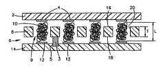
- FIG. 1is a side sectional view of a land grid array (LGA) site according to the present invention, comprising an array of contacts on an electronic module substrate, an array of contacts on a printed circuit board (PCB), and an interposer with electrical conductors disposed between the module and PCB.
- LGAland grid array
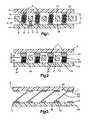
- FIG. 2is another side sectional view of the assembly of FIG. 1, further comprising connective elements.
- FIG. 3is a side sectional view of another assembly according to the present invention.
- FIG. 4is a side perspective view of an assembly of the module and PCB of FIG. 1 according to the present invention.
- FIG. 5is a side sectional view of another assembly according to the present invention.
- FIG. 1a structure and method according to the present invention is provided. Specifically, a side sectional view of an electronic module substrate 2 and a printed circuit board (PCB) 14 is illustrated, showing a land grid array (LGA) site comprising an may of PCB contacts 12 and a corresponding array of module contacts 4 .
- the PCB contacts 12may be continuous with underlying circuitry (not shown) or be part of a through hole structure (not shown).
- an alignment interposer 8Located between the module contacts 4 and the PCB contacts 12 is an alignment interposer 8 , said interposer 8 having a plurality of apertures 9 .
- Disposed within each aperture 9is a deformable conductor 10 .
- the apertures 9are spaced from each other in an array corresponding to the array defined by the module contacts 4 and PCB contacts 124 so that each of the apertures 9 is aligned with one of the module contacts 4 and one of the PCB contacts 12 .
- the alignment of the interposers with the module 2 and PCB 14is achieved by inserting mechanical alignment pins 3 located on the interposer S into receiving holes 5 located on the PCB 14 .
- Interposer to module alignmentis achieved by alignment features, typically cantilever beams, that contact the module substrate edge. Examples of common edge alignment techniques are four-edge cantilever beams or two-edge rigid stops with two-edge cantilever beams.
- One method that may be used with the present inventionis a method and structure described in U.S. patent application Ser. No. 09/800,148, filed Mar. 6, 2001, by William Brodaky, titled “METHOD AND STRUCTURE FOR CONTROLLED SHOCK AND VIBRATION OF ELECTRICAL iNTERCONNECTS,” the disclosure of which is hereby incorporated.
- the contacts 4 and 12may have a width less than the width of the corresponding apertures 9 and, accordingly, the contacts 4 are brought into compressive contact wit the conductors 10 , but not the interposer 8 .
- the widths of contacts 4 and 12may be greater than the apertures 9 widths, resulting in compressive contact of the contacts 4 and 12 with the interposer upper surface 16 and lower surface 18 , respectively.
- the conductor 10 shown in FIG. 1is a wadded wire “fuzz button” connector similar to those produced by Cinch Inc.
- the conductor 10has an inherent resilience that allows the conductor to expand upward and downward, and unrestrained the conductor 10 will expand to a length L larger than that of thickness T of the interposer 8 . Accordingly, when a module contact 4 is brought downward into contact with the interposer top surface 16 across an aperture 9 , and an opposing PCB contact 12 is brought upward into contact with the interposer bottom surface 18 across the same aperture 9 , a conductor 10 disposed within the aperture 9 will be compressed into contact with the contacts 12 and 4 , resulting in an electrical connection between the contacts 12 and 4 . Since the resilient conductor 10 is being forcibly compressed by the contacts 12 and 4 , it exerts forces normal to the contacts 12 and 4 .
- a precious metal wire having a random orientationbe used forte conductor 10 to provide multiple contact points on the contacts 4 and 12 , increasing the reliability of the overall electrical interconnection by providing multiple hertzian or high localized stress contacts.
- Another advantage of a “multiple contacts” conductor 10is that it is better able to penetrate contamination films (not shown) which may be present upon module and PCB electrical contacts 12 and 4 , when compared to a prior art “flat-on-flat” contact system (not shown).
- Alternative embodiments of the conductor 10may be a plated elastomeric member a precious metal plated wire or a stamped metal contact with precious metal plating. Other embodiments may be apparent to one skilled in the art.
- the conductors 10may be permanently attached to the module contacts 4 , the PCB contacts 12 , or both, through a permanent attachment process.
- the conductors 10are shown attached to the module contacts 4 by means of a solder connection 22 .
- the PCB 14is then aligned with the interposer 8 , thereby aligning the conductors 10 with the PCB contacts 12 , and the PCB contacts 12 are brought into electrical contact with the conductors 10 .
- a clamping mechanism 11maintains the compressive connection of the conductor 10 and PCB contacts 12 .
- solder 23can be disposed on the PCB contacts 12 and the solder reflowed to incorporate lower portions of the individual strands 24 of the conductor 10 , thereby creating a permanent connection between the PCB contacts 12 and the conductors 10 , as described above.
- the reflowed solder connections 22incorporate a portion of the strands 24 , the portions incorporated defining engagement regions 28 along the top of the conductors 10 .
- the flowing solder 22In order to restrain the flowing of solder 22 within the engagement regions 28 , the flowing solder 22 must be prevented from “wickiug” along the wire strands 24 and thereby flowing beyond the desired engagement region 28 . This may be accomplished by selectively plating the wire strands 24 beyond the desired engagement region 28 , thereby defining an exclusion region 30 along the conductors 10 , wherein the solder will not adhere to or flow along those plated portions of the strands 24 .
- solder 22is utilized to make the permanent attachment of the conductors 10 to the module contacts 4 in the embodiment shown in FIG. 2, alternate means for permanent attachment may be utilized.
- Example 1an electrically conductive adhesive, specifically Ablebond 8175 made by Ablestick Laboratories, is applied to the PCB contacts 12 .
- the adhesiveis applied by a stencil deposit method, using a 0.005′′ thick stencil with an array of 0.020′′ diameter apertures corresponding to the PCB contact 12 array.
- the adhesive depositsare 0.020′′ in diameter, are hemispherically shaped and are between 0.003-0.004′′ tall.
- the conductors 10are brought into contact with the electrically conductive adhesive deposit
- four point probe measurements of the interconnection between PCB 14 backside and interposer 8 backsideshowed a low contact resistance in the range of about 5 to about 40 milliohms. (There is some variable probe contact resistance in these measurements that may be as high as about 20 to about 30 milliohms).
- the PCB contacts 12were gold plated and had through holes. The adhesive would partially wet down into the through holes but not so much so as to starve the hemispherical deposit and prevent adhesive interconnection between PCB contacts 12 and conductors 10 .
- the conductor wadded wire strands 24were gold plated.
- Noble metal plated surfacesare preferred for low and stable contact resistance interconnections. Additional suitable metallurgical surfaces are palladium, silver and palladium nickel alloys. Nickel, tin, copper and aluminum surfaces provide much higher contact resistance that has significant resistance drift during stress and are, therefore, less suitable for demanding microelectronics interconnection.
- One advantage of using an electrically conductive adhesive over solderis low temperature joining, wherein temperatures may be less than or equal to about 150° C. Another advantage is that there is no requirement that the conductors 10 have a non-wettable surface to prevent solder wicking.
- thermoplastic electrically conductive adhesivessuch as Staystik 181 manufactured by Alpha Metals Inc.
- the wet thermoplastic adhesivewith the solvent not yet driven off, is used to wet the conductor 10 .
- a bond cyclethen drives off the solvent, developing the electrical conducting network and adhesively bonding the conductors 10 to the PCB contacts 12 . If the interposer 8 and conductor 10 need to be removed from the PCB 14 , heat and mechanical force could be used to disengage the conductor 10 from the PCB contacts 12 .
- the exclusion regions 30 along the conductors 10may freely deform or flex without the rigidity imparted by the solder 22 , in contrast to those strand 24 portions embedded in the rigid solder connections 22 . Accordingly, the conductor 10 may elastically deform laterally and vertically in response to movement of the module contact 4 relative to the PCB contact 12 .
- CTEcoefficients of thermal expansion
- ceramic modulestypically have CTE's ranging from 2 to 10 parts-per-million (ppm)
- PCB fabricated from epoxy resin/fiber cloth substratestypically have CTE's ranging from about 15 to 20 ppm, where the fiber cloth may be composed of glass, kevlar or other fibers.
- the thermal mismatch thus describedresults in inelastic strains within the solder column and its attachment points to the module and PCB contacts every time a prior art module/solder connection/PCB assembly heats up and cools down.
- the resilient conductor 10 exclusion region 30may elastically deform laterally responsive to movement of the module substrate 4 relative to the PCB 10 , and thereby reduce strain damage imposed on the solder connection 22 and the compressive connection 32 .
- thermal cycling, electrical operation and mechanical vibrationsresult in longitudinal forces acting upon the conductors 10 as the module 2 and PCB 14 tend to move vertically with respect to each other.
- the interposer 8may impart structural integrity to the module/conductor/PCB assembly 26 .
- the sidewalls 20 of the apertures 9are straight-sided.
- Alternative sidewall embodimentsmay be contoured (not shown).
- the shape of sidewall 20may be specified to provide a desired structural function.
- a contoured sidewall 20can improve reliability of the assembly by providing additional room for contact conductors to deform laterally.
- the assembly 26can be readily disassembled by field technicians and reassembled without the need for breaking and reforming conductive adhesive connections. This provides an advantage over prior art fixed connections in terms of time and ease of serviceability of the assembly 26 .
- soldermay be permitted to entirely wet the conductor 10 , and thereby form a continuous solder hierarchy connection between the contacts 4 and 12 . In this way, a solder column with integral conductor 10 is formed. As with the prior art solder column (not shown), this type of contact 4 -to-contact 12 connection is rigid. However, the strands 24 of the conductors 10 will serve to reinforce the solder connection (not shown) formed thereby, and may result in a solder column-type connection of superior life and fatigue and stress resistance compared to a prior art solder column.
- the conductors 50are pre-stamped and formed single-wire leaf spring structures, affixed to the contacts 4 and 12 with an electrically conductive adhesive 58 to form a composite structure 56 .
- the structure 56is formed by disposing each of the conductors 50 within an aperture 9 of the interposer 8 (not shown) and aligning the interposer 8 with the module contacts 4 wherein each of the conductor top interfaces 52 is aligned with one module contact 4 , as described above and illustrated in FIGS. 1 and 2.
- the conductor top interfaces 52are affixed to the module contacts 4 with the conductive adhesive 58 , as described above, and the interposer 8 is removed.
- the conductor bottom interfaces 54are aligned with the PCB contacts 12 via an alignment means and affixed to the PCB contacts 12 with the conductive adhesive 58 .
- the conductor bottom interfaces 54may be aligned with the PCB contacts 12 via a split prism vision system, as is well known in the art.
- the interposer 8may be left in place to impart alignment and structural features to the resultant assembly.
- the interposer insulator 8 used to align the conductors 10 and 50may be used only as a manufacturing fixture, being removed after the first conductor end is attached. As utilized for the structure 56 of FIG. 3, it may be a disposable member, used as a process carrier for the conductors 50 and then removed and discarded (or kept for reuse) prior to the final assembly of structure 56 . Or it may remain with the conductors 10 in the final assembly 26 of FIG. 2, and thereby enable a compressive connection between one or both of the module contacts 4 and PCB contacts 12 and the conductor 10 , and further impart structural form and integrity to the assembly 26 .
- the resilient leaf-spring structure of the conductors 50allow them to deflect and deform relative to their contact interfaces 52 and 54 . Accordingly, the conductor 50 may deform laterally and vertically in response to movement of the module contacts 4 relative to the PCB contacts 12 responsive to heating and cooling cycles and mechanical vibrations acting upon the assembly 56 , reducing stress upon the adhesive connections of the contact interfaces 52 and 54 and the module contacts 4 and PCB contacts 12 , respectively, and thereby providing improved resistance to fatigue failures of the contact interfaces.
- the present inventiontherefore, provides for a fixed connection between module and PCB contacts with a superior reliability to that of a prior art solder connection.
- two resilient wadded wire conductors 10are electrically interconnected within one of the apertures 9 with electrically conductive adhesives by applying adhesive to one conductor 10 by automated syringe dispenser, or with a pin transfer process. Stencil deposition may be difficult because of their location within the aperture 9 . Noble metal surfaces are preferred for the conductors 10 , resulting in a contact resistance that is low and stable through environmental stress.
- Another type of conductor (not shown) that may be used with the present inventionis the helical formed flexible power connection described in IBM Technical Bulletin No. 94A 61579, Vol. 37, Pub. No. 5, May, 1994, entitled “Flexible Power Connection for Array Applications”, the disclosure of which is hereby incorporated.
Landscapes
- Engineering & Computer Science (AREA)
- Metallurgy (AREA)
- Manufacturing & Machinery (AREA)
- Microelectronics & Electronic Packaging (AREA)
- Coupling Device And Connection With Printed Circuit (AREA)
Abstract
Description
Claims (10)
Priority Applications (1)
| Application Number | Priority Date | Filing Date | Title |
|---|---|---|---|
| US09/871,554US6695623B2 (en) | 2001-05-31 | 2001-05-31 | Enhanced electrical/mechanical connection for electronic devices |
Applications Claiming Priority (1)
| Application Number | Priority Date | Filing Date | Title |
|---|---|---|---|
| US09/871,554US6695623B2 (en) | 2001-05-31 | 2001-05-31 | Enhanced electrical/mechanical connection for electronic devices |
Publications (2)
| Publication Number | Publication Date |
|---|---|
| US20020182900A1 US20020182900A1 (en) | 2002-12-05 |
| US6695623B2true US6695623B2 (en) | 2004-02-24 |
Family
ID=25357694
Family Applications (1)
| Application Number | Title | Priority Date | Filing Date |
|---|---|---|---|
| US09/871,554Expired - Fee RelatedUS6695623B2 (en) | 2001-05-31 | 2001-05-31 | Enhanced electrical/mechanical connection for electronic devices |
Country Status (1)
| Country | Link |
|---|---|
| US (1) | US6695623B2 (en) |
Cited By (24)
| Publication number | Priority date | Publication date | Assignee | Title |
|---|---|---|---|---|
| US20030003779A1 (en)* | 2000-01-20 | 2003-01-02 | Rathburn James J | Flexible compliant interconnect assembly |
| US20040002233A1 (en)* | 2002-06-28 | 2004-01-01 | International Business Machines Corporation | Method of assembling an interconnect device assembly and apparatus therefor |
| US20040029411A1 (en)* | 2000-01-20 | 2004-02-12 | Rathburn James J. | Compliant interconnect assembly |
| US20040214468A1 (en)* | 2003-04-22 | 2004-10-28 | Rwei Ching Chang | Electrical connector |
| US20040217770A1 (en)* | 2003-05-01 | 2004-11-04 | Diorio Mark L | Planarizing and testing of BGA packages |
| US6830460B1 (en)* | 1999-08-02 | 2004-12-14 | Gryphics, Inc. | Controlled compliance fine pitch interconnect |
| US20050164534A1 (en)* | 2003-03-24 | 2005-07-28 | Che-Yu Li | Interconnection device and system |
| US7171745B2 (en) | 2002-08-02 | 2007-02-06 | National Semiconductor Corporation | Apparatus and method for force mounting semiconductor packages to printed circuit boards |
| US20070094874A1 (en)* | 2004-08-13 | 2007-05-03 | Tessera, Inc. | Methods for forming connection structures for microelectronic devices |
| US20070134948A1 (en)* | 2005-12-08 | 2007-06-14 | International Business Machines Corporation | Method and apparatus for electrically connecting two substrates using a resilient wire bundle captured in an aperture of an interposer by a retention member |
| US20080224288A1 (en)* | 2005-03-30 | 2008-09-18 | Nxp B.V. | Portable Object Connectable Package |
| US7667473B1 (en)* | 2005-09-28 | 2010-02-23 | Xilinx, Inc | Flip-chip package having thermal expansion posts |
| US20100065198A1 (en)* | 2005-12-09 | 2010-03-18 | Xerox Corporation | Electrical interconnect with maximized electrical contact |
| US20100243303A1 (en)* | 2006-08-22 | 2010-09-30 | Hitachi Chemical Company, Ltd. | Circuit connecting material, connection structure of circuit member, and method for manufacturing connection structure of circuit member |
| US20110078821A1 (en)* | 2008-04-09 | 2011-03-31 | University Of Florida Research Foundation, Inc. | Heat resistant plants and plant tissues and methods and materials for making and using same |
| US20130333935A1 (en)* | 2012-06-19 | 2013-12-19 | Lockheed Martin Corporation | High reliability fluid-tight low-profile electrically conductive interconnects for large scale frame attachment |
| US20160084905A1 (en)* | 2014-09-24 | 2016-03-24 | Micron Technology, Inc. | Apparatus for testing stacked die assemblies, and related methods |
| US9365947B2 (en) | 2013-10-04 | 2016-06-14 | Invensas Corporation | Method for preparing low cost substrates |
| US9515030B2 (en) | 2013-03-14 | 2016-12-06 | Lockheed Martin Corporation | X-ray obscuration film and related techniques |
| WO2017023037A1 (en)* | 2015-08-04 | 2017-02-09 | 주식회사 아이에스시 | Test socket |
| US9894760B2 (en) | 2012-08-09 | 2018-02-13 | Lockheed Martin Corporation | Conformal 3D non-planar multi-layer circuitry |
| US10123410B2 (en) | 2014-10-10 | 2018-11-06 | Lockheed Martin Corporation | Fine line 3D non-planar conforming circuit |
| US10141668B1 (en)* | 2017-07-06 | 2018-11-27 | Palo Alto Research Center Incorporated | Detachable flex-to-flex electrical connection |
| US11811182B2 (en)* | 2018-10-11 | 2023-11-07 | Intel Corporation | Solderless BGA interconnect |
Families Citing this family (10)
| Publication number | Priority date | Publication date | Assignee | Title |
|---|---|---|---|---|
| US7245022B2 (en)* | 2003-11-25 | 2007-07-17 | International Business Machines Corporation | Semiconductor module with improved interposer structure and method for forming the same |
| DE602005002118D1 (en)* | 2005-01-21 | 2007-10-04 | Barcoview Texen | Device which allows the heat transfer, in particular from a component or an electronic card to a frame or to a cooler connected to the frame |
| US7083431B1 (en) | 2005-09-02 | 2006-08-01 | Lear Corporation | Method and system of electrically connecting multiple printed circuit boards |
| WO2007038132A1 (en)* | 2005-09-21 | 2007-04-05 | Jones Eric T | Fuel cell device |
| TWI337511B (en)* | 2007-08-02 | 2011-02-11 | Asustek Comp Inc | Electronic device and elastic sheet unit thereof |
| US7530814B2 (en)* | 2007-09-25 | 2009-05-12 | Intel Corporation | Providing variable sized contacts for coupling with a semiconductor device |
| US8400539B2 (en)* | 2008-11-12 | 2013-03-19 | Bae Systems Information And Electronic Systems Integration Inc. | High density composite focal plane array |
| FR3127097B1 (en)* | 2021-09-15 | 2025-07-11 | Commissariat Energie Atomique | Manufacturing process of a multilayer electronic circuit |
| US20230253748A1 (en)* | 2022-02-08 | 2023-08-10 | e-con Systems India Private Limited | Method for Securing the Electrical Contacts in a Connector System |
| CN116600469B (en)* | 2023-07-17 | 2023-09-22 | 北京三重华星电子科技有限公司 | Printed circuit board with soldered electronic components |
Citations (22)
| Publication number | Priority date | Publication date | Assignee | Title |
|---|---|---|---|---|
| US4574331A (en) | 1983-05-31 | 1986-03-04 | Trw Inc. | Multi-element circuit construction |
| US4581679A (en) | 1983-05-31 | 1986-04-08 | Trw Inc. | Multi-element circuit construction |
| US5007841A (en) | 1983-05-31 | 1991-04-16 | Trw Inc. | Integrated-circuit chip interconnection system |
| US5222014A (en) | 1992-03-02 | 1993-06-22 | Motorola, Inc. | Three-dimensional multi-chip pad array carrier |
| US5324205A (en) | 1993-03-22 | 1994-06-28 | International Business Machines Corporation | Array of pinless connectors and a carrier therefor |
| US5362421A (en)* | 1993-06-16 | 1994-11-08 | Minnesota Mining And Manufacturing Company | Electrically conductive adhesive compositions |
| US5380212A (en)* | 1992-08-14 | 1995-01-10 | Hewlett Packard Company | Conductive elastomeric interface for a pin grid array |
| US5598033A (en) | 1995-10-16 | 1997-01-28 | Advanced Micro Devices, Inc. | Micro BGA stacking scheme |
| US5704794A (en) | 1986-12-29 | 1998-01-06 | Labinal Components And Systems, Inc. | Electrical connectors |
| US5810607A (en) | 1995-09-13 | 1998-09-22 | International Business Machines Corporation | Interconnector with contact pads having enhanced durability |
| US5967804A (en) | 1987-03-04 | 1999-10-19 | Canon Kabushiki Kaisha | Circuit member and electric circuit device with the connecting member |
| US5990563A (en) | 1995-12-29 | 1999-11-23 | Lg Semicon Co., Ltd. | Semiconductor package having a connection member |
| US6007349A (en) | 1996-01-04 | 1999-12-28 | Tessera, Inc. | Flexible contact post and post socket and associated methods therefor |
| US6008071A (en)* | 1995-09-20 | 1999-12-28 | Fujitsu Limited | Method of forming solder bumps onto an integrated circuit device |
| US6033233A (en)* | 1997-11-28 | 2000-03-07 | Fujitsu Limited | Electrical connecting device, and semiconductor device testing method |
| US6032356A (en)* | 1993-11-16 | 2000-03-07 | Formfactor. Inc. | Wafer-level test and burn-in, and semiconductor process |
| US6050832A (en)* | 1998-08-07 | 2000-04-18 | Fujitsu Limited | Chip and board stress relief interposer |
| US6062879A (en)* | 1995-11-27 | 2000-05-16 | International Business Machines Corporation | High density test probe with rigid surface structure |
| US6132222A (en)* | 1998-12-28 | 2000-10-17 | Hon Hai Precision Ind. Co., Ltd. | BGA socket terminal |
| US6174174B1 (en)* | 1998-01-16 | 2001-01-16 | Sony Corporation | Socket for IC and method for manufacturing IC |
| US6247635B1 (en)* | 1996-11-14 | 2001-06-19 | Berg Technology, Inc. | High density connector having a ball type of contact surface |
| US6541867B1 (en)* | 1996-12-13 | 2003-04-01 | Tessera, Inc. | Microelectronic connector with planar elastomer sockets |
- 2001
- 2001-05-31USUS09/871,554patent/US6695623B2/ennot_activeExpired - Fee Related
Patent Citations (23)
| Publication number | Priority date | Publication date | Assignee | Title |
|---|---|---|---|---|
| US4581679A (en) | 1983-05-31 | 1986-04-08 | Trw Inc. | Multi-element circuit construction |
| US5007841A (en) | 1983-05-31 | 1991-04-16 | Trw Inc. | Integrated-circuit chip interconnection system |
| US5315481A (en) | 1983-05-31 | 1994-05-24 | Trw Inc. | Packaging construction for semiconductor wafers |
| US4574331A (en) | 1983-05-31 | 1986-03-04 | Trw Inc. | Multi-element circuit construction |
| US5704794A (en) | 1986-12-29 | 1998-01-06 | Labinal Components And Systems, Inc. | Electrical connectors |
| US5967804A (en) | 1987-03-04 | 1999-10-19 | Canon Kabushiki Kaisha | Circuit member and electric circuit device with the connecting member |
| US5222014A (en) | 1992-03-02 | 1993-06-22 | Motorola, Inc. | Three-dimensional multi-chip pad array carrier |
| US5380212A (en)* | 1992-08-14 | 1995-01-10 | Hewlett Packard Company | Conductive elastomeric interface for a pin grid array |
| US5324205A (en) | 1993-03-22 | 1994-06-28 | International Business Machines Corporation | Array of pinless connectors and a carrier therefor |
| US5362421A (en)* | 1993-06-16 | 1994-11-08 | Minnesota Mining And Manufacturing Company | Electrically conductive adhesive compositions |
| US6032356A (en)* | 1993-11-16 | 2000-03-07 | Formfactor. Inc. | Wafer-level test and burn-in, and semiconductor process |
| US5810607A (en) | 1995-09-13 | 1998-09-22 | International Business Machines Corporation | Interconnector with contact pads having enhanced durability |
| US6008071A (en)* | 1995-09-20 | 1999-12-28 | Fujitsu Limited | Method of forming solder bumps onto an integrated circuit device |
| US5598033A (en) | 1995-10-16 | 1997-01-28 | Advanced Micro Devices, Inc. | Micro BGA stacking scheme |
| US6062879A (en)* | 1995-11-27 | 2000-05-16 | International Business Machines Corporation | High density test probe with rigid surface structure |
| US5990563A (en) | 1995-12-29 | 1999-11-23 | Lg Semicon Co., Ltd. | Semiconductor package having a connection member |
| US6007349A (en) | 1996-01-04 | 1999-12-28 | Tessera, Inc. | Flexible contact post and post socket and associated methods therefor |
| US6247635B1 (en)* | 1996-11-14 | 2001-06-19 | Berg Technology, Inc. | High density connector having a ball type of contact surface |
| US6541867B1 (en)* | 1996-12-13 | 2003-04-01 | Tessera, Inc. | Microelectronic connector with planar elastomer sockets |
| US6033233A (en)* | 1997-11-28 | 2000-03-07 | Fujitsu Limited | Electrical connecting device, and semiconductor device testing method |
| US6174174B1 (en)* | 1998-01-16 | 2001-01-16 | Sony Corporation | Socket for IC and method for manufacturing IC |
| US6050832A (en)* | 1998-08-07 | 2000-04-18 | Fujitsu Limited | Chip and board stress relief interposer |
| US6132222A (en)* | 1998-12-28 | 2000-10-17 | Hon Hai Precision Ind. Co., Ltd. | BGA socket terminal |
Non-Patent Citations (1)
| Title |
|---|
| IBM Technical Disclosure Bulletin, vol. 37, entitled "Flexible Power Connection for Array Applications", May, 1994, 2 pp. |
Cited By (54)
| Publication number | Priority date | Publication date | Assignee | Title |
|---|---|---|---|---|
| US6830460B1 (en)* | 1999-08-02 | 2004-12-14 | Gryphics, Inc. | Controlled compliance fine pitch interconnect |
| US7160119B2 (en) | 1999-08-02 | 2007-01-09 | Gryphics, Inc. | Controlled compliance fine pitch electrical interconnect |
| US20050099763A1 (en)* | 1999-08-02 | 2005-05-12 | Gryphics, Inc. | Controlled compliance fine pitch electrical interconnect |
| US6957963B2 (en) | 2000-01-20 | 2005-10-25 | Gryphics, Inc. | Compliant interconnect assembly |
| US7114960B2 (en) | 2000-01-20 | 2006-10-03 | Gryhics, Inc. | Compliant interconnect assembly |
| US20030003779A1 (en)* | 2000-01-20 | 2003-01-02 | Rathburn James J | Flexible compliant interconnect assembly |
| US20040029411A1 (en)* | 2000-01-20 | 2004-02-12 | Rathburn James J. | Compliant interconnect assembly |
| US20050101164A1 (en)* | 2000-01-20 | 2005-05-12 | Gryphics, Inc. | Compliant interconnect assembly |
| US7900347B2 (en) | 2000-01-20 | 2011-03-08 | Cascade Microtech, Inc. | Method of making a compliant interconnect assembly |
| US20050233609A1 (en)* | 2000-01-20 | 2005-10-20 | Gryphics, Inc. | Compliant interconnect assembly |
| US7121839B2 (en) | 2000-01-20 | 2006-10-17 | Gryphics, Inc. | Compliant interconnect assembly |
| US6988310B2 (en)* | 2002-06-28 | 2006-01-24 | International Business Machines Corporation | Method of assembling an interconnect device assembly |
| US20040002233A1 (en)* | 2002-06-28 | 2004-01-01 | International Business Machines Corporation | Method of assembling an interconnect device assembly and apparatus therefor |
| US7171745B2 (en) | 2002-08-02 | 2007-02-06 | National Semiconductor Corporation | Apparatus and method for force mounting semiconductor packages to printed circuit boards |
| US20050164534A1 (en)* | 2003-03-24 | 2005-07-28 | Che-Yu Li | Interconnection device and system |
| US7040902B2 (en) | 2003-03-24 | 2006-05-09 | Che-Yu Li & Company, Llc | Electrical contact |
| US7029289B2 (en)* | 2003-03-24 | 2006-04-18 | Che-Yu Li & Company Llc | Interconnection device and system |
| US20040214468A1 (en)* | 2003-04-22 | 2004-10-28 | Rwei Ching Chang | Electrical connector |
| US20040217770A1 (en)* | 2003-05-01 | 2004-11-04 | Diorio Mark L | Planarizing and testing of BGA packages |
| US20070094874A1 (en)* | 2004-08-13 | 2007-05-03 | Tessera, Inc. | Methods for forming connection structures for microelectronic devices |
| US7793414B2 (en)* | 2004-08-13 | 2010-09-14 | Tessera, Inc. | Methods for forming connection structures for microelectronic devices |
| US20080224288A1 (en)* | 2005-03-30 | 2008-09-18 | Nxp B.V. | Portable Object Connectable Package |
| US7692280B2 (en)* | 2005-03-30 | 2010-04-06 | St-Ericsson Sa | Portable object connectable package |
| US7667473B1 (en)* | 2005-09-28 | 2010-02-23 | Xilinx, Inc | Flip-chip package having thermal expansion posts |
| US7293994B2 (en) | 2005-12-08 | 2007-11-13 | International Business Machines Corporation | Method and apparatus for electrically connecting two substrates using a resilient wire bundle captured in an aperture of an interposer by a retention member |
| US20070227769A1 (en)* | 2005-12-08 | 2007-10-04 | Brodsky William L | Method and Apparatus for Electrically Connecting Two Substrates Using a Resilient Wire Bundle Captured in an Aperture of an Interposer by a Retention Member |
| US7765693B2 (en) | 2005-12-08 | 2010-08-03 | International Business Machines Corporation | Electrically connecting two substrates using a resilient wire bundle captured in an aperture of an interposer by a retention member |
| US20070226997A1 (en)* | 2005-12-08 | 2007-10-04 | Brodsky William L | Method and Apparatus for Electrically Connecting Two Substrates Using a Resilient Wire Bundle Captured in an Aperture of an Interposer by a Retention Member |
| US20080282539A1 (en)* | 2005-12-08 | 2008-11-20 | International Business Machines Corporation | Electrically Connecting Two Substrates Using a Resilient Wire Bundle Captured in an Aperture of an Interposer by a Retention Member |
| US20070134948A1 (en)* | 2005-12-08 | 2007-06-14 | International Business Machines Corporation | Method and apparatus for electrically connecting two substrates using a resilient wire bundle captured in an aperture of an interposer by a retention member |
| US8621750B2 (en)* | 2005-12-09 | 2014-01-07 | Xerox Corporation | Method of making an electrical circuit structure |
| US20100065198A1 (en)* | 2005-12-09 | 2010-03-18 | Xerox Corporation | Electrical interconnect with maximized electrical contact |
| US20100243303A1 (en)* | 2006-08-22 | 2010-09-30 | Hitachi Chemical Company, Ltd. | Circuit connecting material, connection structure of circuit member, and method for manufacturing connection structure of circuit member |
| US20110078821A1 (en)* | 2008-04-09 | 2011-03-31 | University Of Florida Research Foundation, Inc. | Heat resistant plants and plant tissues and methods and materials for making and using same |
| US20130333935A1 (en)* | 2012-06-19 | 2013-12-19 | Lockheed Martin Corporation | High reliability fluid-tight low-profile electrically conductive interconnects for large scale frame attachment |
| US8878072B2 (en)* | 2012-06-19 | 2014-11-04 | Lockheed Martin Corporation | High reliability fluid-tight low-profile electrically conductive interconnects for large scale frame attachment |
| US10827608B2 (en) | 2012-08-09 | 2020-11-03 | Lockheed Martin Corporation | Conformal 3D non-planar multi-layer circuitry |
| US10568204B2 (en) | 2012-08-09 | 2020-02-18 | Lockheed Martin Corporation | Conformal 3D non-planar multi-layer circuitry |
| US9894760B2 (en) | 2012-08-09 | 2018-02-13 | Lockheed Martin Corporation | Conformal 3D non-planar multi-layer circuitry |
| US9515030B2 (en) | 2013-03-14 | 2016-12-06 | Lockheed Martin Corporation | X-ray obscuration film and related techniques |
| US9812228B2 (en) | 2013-03-14 | 2017-11-07 | Lockheed Martin Corporation | X-ray obscuration film and related techniques |
| US9365947B2 (en) | 2013-10-04 | 2016-06-14 | Invensas Corporation | Method for preparing low cost substrates |
| US10283484B2 (en) | 2013-10-04 | 2019-05-07 | Invensas Corporation | Low cost substrates |
| US20170336470A1 (en)* | 2014-09-24 | 2017-11-23 | Micron Technology, Inc. | Methods of testing semiconductor devices |
| US9733304B2 (en)* | 2014-09-24 | 2017-08-15 | Micron Technology, Inc. | Semiconductor device test apparatuses |
| US10126357B2 (en)* | 2014-09-24 | 2018-11-13 | Micron Technology, Inc. | Methods of testing semiconductor devices comprising a die stack having protruding conductive elements |
| US20160084905A1 (en)* | 2014-09-24 | 2016-03-24 | Micron Technology, Inc. | Apparatus for testing stacked die assemblies, and related methods |
| US20190072608A1 (en)* | 2014-09-24 | 2019-03-07 | Micron Technology, Inc. | Semiconductor device test apparatuses |
| US10481200B2 (en)* | 2014-09-24 | 2019-11-19 | Micron Technology, Inc. | Semiconductor device test apparatuses comprising at least one test site having an array of pockets |
| US10123410B2 (en) | 2014-10-10 | 2018-11-06 | Lockheed Martin Corporation | Fine line 3D non-planar conforming circuit |
| US10154584B2 (en) | 2014-10-10 | 2018-12-11 | Lockheed Martin Corporation | Method of producing a fine line 3D non-planar conforming circuit |
| WO2017023037A1 (en)* | 2015-08-04 | 2017-02-09 | 주식회사 아이에스시 | Test socket |
| US10141668B1 (en)* | 2017-07-06 | 2018-11-27 | Palo Alto Research Center Incorporated | Detachable flex-to-flex electrical connection |
| US11811182B2 (en)* | 2018-10-11 | 2023-11-07 | Intel Corporation | Solderless BGA interconnect |
Also Published As
| Publication number | Publication date |
|---|---|
| US20020182900A1 (en) | 2002-12-05 |
Similar Documents
| Publication | Publication Date | Title |
|---|---|---|
| US6695623B2 (en) | Enhanced electrical/mechanical connection for electronic devices | |
| KR100408948B1 (en) | How to Mount Electronic Components on a Circuit Board | |
| US6177729B1 (en) | Rolling ball connector | |
| US5525545A (en) | Semiconductor chip assemblies and components with pressure contact | |
| US6386890B1 (en) | Printed circuit board to module mounting and interconnecting structure and method | |
| US7004760B2 (en) | Connector and an electronic apparatus having electronic parts connected to each other by the connector | |
| US7176043B2 (en) | Microelectronic packages and methods therefor | |
| US5528462A (en) | Direct chip connection using demountable flip chip package | |
| US6320397B1 (en) | Molded plastic carrier for testing semiconductor dice | |
| US6493932B1 (en) | Lidless socket and method of making same | |
| US7005751B2 (en) | Layered microelectronic contact and method for fabricating same | |
| US6224396B1 (en) | Compliant, surface-mountable interposer | |
| EP0852397B1 (en) | Cantilevered ball connection for integrated circuit chip package | |
| US6287126B1 (en) | Mechanical attachment means used as electrical connection | |
| US20080185705A1 (en) | Microelectronic packages and methods therefor | |
| JP2004006862A (en) | Subminiature electronic contact and integrated body | |
| US6652290B2 (en) | Connecting devices and method for interconnecting circuit components | |
| US8541685B2 (en) | Flexible harness and electrical connector cable using same | |
| KR980013574A (en) | Column Grid Array Substrate Attachment with Geat Sink Stress Rdlief | |
| KR101267651B1 (en) | Microelectronic assemblies having compliancy | |
| US20120258636A1 (en) | Connecting terminal structure, socket and electronic package | |
| EP0838100B1 (en) | Separable electrical connector assembly having a planar array of conductive protrusions | |
| US6723927B1 (en) | High-reliability interposer for low cost and high reliability applications | |
| US7518238B2 (en) | Mounting flexible circuits onto integrated circuit substrates | |
| KR19990030098A (en) | Pre-operation test device |
Legal Events
| Date | Code | Title | Description |
|---|---|---|---|
| AS | Assignment | Owner name:INTERNATIONAL BUSINESS MACHINES CORPORATION, NEW Y Free format text:ASSIGNMENT OF ASSIGNORS INTEREST;ASSIGNORS:BRODSKY, WILLIAM LOUIS;CALETKA, DAVID V.;GAYNES, MICHAEL ANTHONY;AND OTHERS;REEL/FRAME:011893/0127;SIGNING DATES FROM 20010524 TO 20010530 | |
| FEPP | Fee payment procedure | Free format text:PAYOR NUMBER ASSIGNED (ORIGINAL EVENT CODE: ASPN); ENTITY STATUS OF PATENT OWNER: LARGE ENTITY | |
| FPAY | Fee payment | Year of fee payment:4 | |
| AS | Assignment | Owner name:GOOGLE INC., CALIFORNIA Free format text:ASSIGNMENT OF ASSIGNORS INTEREST;ASSIGNOR:INTERNATIONAL BUSINESS MACHINES CORPORATION;REEL/FRAME:026894/0001 Effective date:20110817 | |
| REMI | Maintenance fee reminder mailed | ||
| FPAY | Fee payment | Year of fee payment:8 | |
| SULP | Surcharge for late payment | Year of fee payment:7 | |
| REMI | Maintenance fee reminder mailed | ||
| LAPS | Lapse for failure to pay maintenance fees | ||
| STCH | Information on status: patent discontinuation | Free format text:PATENT EXPIRED DUE TO NONPAYMENT OF MAINTENANCE FEES UNDER 37 CFR 1.362 | |
| FP | Lapsed due to failure to pay maintenance fee | Effective date:20160224 | |
| AS | Assignment | Owner name:GOOGLE LLC, CALIFORNIA Free format text:CHANGE OF NAME;ASSIGNOR:GOOGLE INC.;REEL/FRAME:044144/0001 Effective date:20170929 | |
| AS | Assignment | Owner name:GOOGLE LLC, CALIFORNIA Free format text:CORRECTIVE ASSIGNMENT TO CORRECT THE THE REMOVAL OF THE INCORRECTLY RECORDED APPLICATION NUMBERS 14/149802 AND 15/419313 PREVIOUSLY RECORDED AT REEL: 44144 FRAME: 1. ASSIGNOR(S) HEREBY CONFIRMS THE CHANGE OF NAME;ASSIGNOR:GOOGLE INC.;REEL/FRAME:068092/0502 Effective date:20170929 |