US6694221B2 - Controlled inventory device and method using pressure transducer - Google Patents
Controlled inventory device and method using pressure transducerDownload PDFInfo
- Publication number
- US6694221B2 US6694221B2US10/008,612US861201AUS6694221B2US 6694221 B2US6694221 B2US 6694221B2US 861201 AUS861201 AUS 861201AUS 6694221 B2US6694221 B2US 6694221B2
- Authority
- US
- United States
- Prior art keywords
- user
- items
- weight
- bin
- transaction
- Prior art date
- Legal status (The legal status is an assumption and is not a legal conclusion. Google has not performed a legal analysis and makes no representation as to the accuracy of the status listed.)
- Expired - Fee Related, expires
Links
Images


Classifications
- G—PHYSICS
- G07—CHECKING-DEVICES
- G07F—COIN-FREED OR LIKE APPARATUS
- G07F5/00—Coin-actuated mechanisms; Interlocks
- G07F5/26—Interlocks, e.g. for locking the doors of compartments other than that to be used
- G—PHYSICS
- G06—COMPUTING OR CALCULATING; COUNTING
- G06Q—INFORMATION AND COMMUNICATION TECHNOLOGY [ICT] SPECIALLY ADAPTED FOR ADMINISTRATIVE, COMMERCIAL, FINANCIAL, MANAGERIAL OR SUPERVISORY PURPOSES; SYSTEMS OR METHODS SPECIALLY ADAPTED FOR ADMINISTRATIVE, COMMERCIAL, FINANCIAL, MANAGERIAL OR SUPERVISORY PURPOSES, NOT OTHERWISE PROVIDED FOR
- G06Q10/00—Administration; Management
- G06Q10/08—Logistics, e.g. warehousing, loading or distribution; Inventory or stock management
- G06Q10/087—Inventory or stock management, e.g. order filling, procurement or balancing against orders
- G—PHYSICS
- G07—CHECKING-DEVICES
- G07F—COIN-FREED OR LIKE APPARATUS
- G07F9/00—Details other than those peculiar to special kinds or types of apparatus
- G07F9/02—Devices for alarm or indication, e.g. when empty; Advertising arrangements in coin-freed apparatus
- G07F9/026—Devices for alarm or indication, e.g. when empty; Advertising arrangements in coin-freed apparatus for alarm, monitoring and auditing in vending machines or means for indication, e.g. when empty
Definitions
- the present inventionrelates to inventory management systems for consumable supply items. More specifically, the present invention relates to a method and apparatus for providing controlled access to supply items and automatically determining changes in inventory levels.
- the inventory of supply items characterized by a low per-item costis typically managed by physical inspection of the quantity of items present.
- these types of supply itemssuch as office supplies or industrial supplies, are utilized by a large variety of businesses, the use of known controlled inventory systems is not economically justified in these low per-item cost applications.
- inventory control by physical inspectionmay be unreliable and often results in depletion of certain supply items before a restocking order is generated.
- the preferred embodiments of the present inventionprovide an economically-feasible system for use with relatively low per-item cost supplies, such as office supplies or industrial supplies, which accurately manages inventory levels to ensure a sufficient level of supply items are available. These systems are especially advantageous for providing controlled access to such low per-item cost supplies.
- One aspect of a preferred controlled inventory systemis an office supply dispensing apparatus including a cabinet defining an enclosed space and having at least one door. The at least one door has a secured position wherein access to the enclosed space is prevented.
- the cabinetincludes at least one surface within the enclosed space, wherein the at least one surface is configured to receive a quantity of an office supply item.
- the dispensing apparatusincludes a controlled inventory arrangement comprising a memory for storing a programmable protocol, a processor for processing the programmable protocol, and a user interface electrically connected to the processor. The user interface is configured to receive a user identification input.
- the controlled inventory arrangementalso includes a weight sensor electrically connected to the processor, wherein the weight sensor is operatively associated with the at least one surface to determine the weight of the quantity of office supply items.
- the controlled inventory systemis configured to release the at least one door from the secured position in response to processing of the programmable protocol upon receiving an approved user identification input.
- the controlled inventory arrangementis additionally configured to determine a change in the quantity of office supply items in response to processing of the programmable protocol upon determining a change in weight of the quantity of office supply items.
- a further aspect of a preferred controlled inventory systemis a perishable item dispensing apparatus including a refrigerated cabinet defining an enclosed space and having at least one door.
- the at least one doorhas a secured position wherein access to the enclosed space is prevented.
- the cabinetincludes at least one surface within the enclosed space, wherein the at least one surface is configured to receive a quantity of a perishable item.
- the dispensing apparatusincludes a controlled inventory arrangement comprising a memory for storing a programmable protocol, a processor for processing the programmable protocol, and a user interface electrically connected to the processor.
- the user interfaceis configured to receive a user identification input.
- the controlled inventory arrangementalso includes a weight sensor electrically connected to the processor, wherein the weight sensor is operatively associated with the at least one surface to determine the weight of the quantity of perishable items.
- the controlled inventory systemis configured to release the at least one door from the secured position in response to processing of the programmable protocol upon receiving an approved user identification input if the current date is before the expiration date of the desired perishable item.
- the controlled inventory arrangementis additionally configured to determine a change in the quantity of perishable items in response to processing of the programmable protocol upon determining a change in weight of the quantity of perishable items.
- Another aspect of the controlled inventory systemincludes a method of controlled dispensing of office supplies.
- the methodincludes providing a secured selection of office supply items, wherein each of the office supply items has a known weight.
- the methodalso includes authenticating the identification of a user of the office supply items and asking the user to select a transaction account.
- the methodfurther includes allowing the user to access a portion of the selection of the office supply items according to predetermined user access rights.
- the methoddetermines a quantity of the office supply items added or removed by the user by determining a change in weight of the office supply items. Further, the method records the addition or removal of the supply items to the transaction account.
- a further aspect of the controlled inventory systemincludes a method of controlled dispensing of consumable supplies.
- the methodincludes the step of providing a secured selection of consumable supply items, each of the items having a known weight.
- the methodfurther includes the step of providing a plurality of bins for storing the items, each bin having an associated weight sensor for determining the weight of the items within the bin.
- the methodadditionally includes authenticating the identification of a user of the items and requesting the user to select a transaction account.
- the methodallows the user to access a portion of the bins according to predetermined user access rights.
- the methodalso includes the steps of determining a quantity of the items added or removed from one of the plurality of bins by the user by determining a change in a weight of the bin and recording the addition or removal of the items to the transaction account.
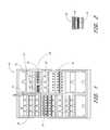
- FIG. 1is a schematic illustration of the front side of a preferred dispensing cabinet, which encloses a plurality of bins for holding supply items. Each bin is mounted on an associated weight sensor;
- FIG. 2is an enlarged bin and weight sensor of FIG. 1 .
- the weight sensorincludes an indicator light;
- FIG. 3is a schematic illustration of the electronic layout of the preferred apparatus of FIG. 1, including a communications link to a remote data server;
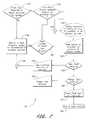
- FIG. 4is an operational flow diagram for a preferred method of controlled dispensing of supply items
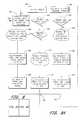
- FIG. 5is an operational flow diagram for an optional self-registration routine for the preferred method of FIG. 4;
- FIG. 6is an operational flow diagram for a method of restricting access to supply items based on user or department spending limits
- FIG. 7is an operational flow diagram for an account selection routine for the preferred method of FIG. 4;
- FIG. 8is an operational flow diagram of a weight reading error routine for the preferred method of FIG. 4.
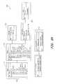
- FIG. 9is a step diagram illustrating a preferred database model for use with the preferred method of FIG. 4 .
- FIG. 1illustrates a preferred embodiment of a dispensing apparatus 10 suitable for providing controlled dispensing of supply items, such as office supplies or industrial supplies.
- the apparatus 10 of FIG. 1is embodied in a cabinet 12 , which defines an enclosed space 14 for at least partially enclosing a plurality of supply items.
- the cabinet 12is made from a suitable material, such as steel, in accordance with conventional fabrication techniques. However, alternative materials, such as alloys and plastic, may also be used.
- An open front side of the cabinet 12is desirably closed by a plurality of doors 16 .
- the open portion of the cabinet 12may encompass the entire front side or a portion thereof.
- the doors 16may be configurable in size and number to suit a desired application.
- Each of the doors 16may be closed and locked into a secured position by a suitable electronically-operated lock assembly (not shown). When in the secured position, the doors 16 prevent access to the supply items within the enclosed space 14 .
- the electronic lock assemblies which hold the doors in the secured positionare desirably controlled by a controller 34 (FIG. 3 ), which will be described in detail below.
- the dispenser 10also desirably includes a user interface 18 which allows communication between the controlled inventory system and a user.
- the user interface 18preferably includes at least an input device 20 , such as a keyboard, and an output device 22 , such as a display screen.
- the input device 20allows a user to input information to the controlled inventory system.
- the output device 22allows the controlled inventory system to communicate information to the user.
- the input and output devices 20 , 22may also assume other suitable arrangements.
- the input device 20preferably also comprises a magnetic card reader, a bar code scanner, and an input port, such as an RS 232 port.
- a plurality of bins 24are provided within the enclosed space 14 for containing the supply items.
- the bins 24are standard, commercially available plastic bins.
- the binsmay be varied in size and shape to allow a variety of supply items to be contained within a single dispensing apparatus 10 .
- Each bin 24rests on an associated weight sensor 26 .
- the bins 24are secured to the associated weight sensor 26 (FIG. 2 ), however, the bins 24 may also be configured to loosely rest upon the weight sensor 26 .
- each bin 24is associated with its own individual weight sensor 26 .
- the dispenser 10may be configured such that multiple bins 24 are supported on a single weight sensor 26 .
- Each of the bins 24 and associated weight sensors 26are supported by a plurality of shelves 28 which are connected to the cabinet 12 . The shelves 28 are also configurable in number and spacing to permit customization of the bin 24 .
- the weight sensors 26are configured to send an output signal to the controlled inventory system upon sensing the weight of the items within an associated bin 24 . In this manner, the weight sensors 26 communicate a change in weight, and thus a change in quantity, of the supply items within an associated bin 24 , as will be described in greater detail below.
- the weight sensors 26may comprise any number of suitable sensors, such as strain gages or piezoelectric sensors, for example.
- each bin 24desirably includes an indicator 30 , such as an LED light.
- the indicator 30is electronically connected to the controlled inventory system and is operable to communicate with a user of the dispenser 10 .
- each bin 24includes a dedicated indicator 30 .
- the indicators 30may be utilized to communicate the location of a desired supply item to a user of the dispenser 10 .
- multiple indicators 30may be utilized in a sequenced pattern to lead a user of the dispenser 10 to a desired supply item by progressing from an area of the cabinet 12 down to a single bin 24 .
- FIG. 3illustrates an electronic communication, or controlled dispensing, arrangement 32 utilized by the controlled inventory system in operating the dispenser 10 to provide controlled dispensing of supply items.
- the electronic communication arrangement 32comprises a controller 34 which processes signals provided by various inputs and in response controls the operation of various external devices of the dispenser 10 .
- the controller 34desirably comprises a memory for storing a programmable protocol and a processor for manipulating the programmable protocol.
- the controller 34advantageously includes a “local” database for storing information.
- the local databaseis desirably provided in addition to a “remote” database, as will be described below.
- the controller 34communicates with various user interface components 36 which allow the control inventory system to communicate with a user. Communication between the controller 34 and the user interface components 36 is achieved through an electronic communication network, or bus, 38 .
- the illustrated user interface components 36include various input devices, such as a keyboard or a bar code scanner 40 , a magnetic card reader 42 and an input port 44 .
- the user interface components 36include an output device embodied by a display screen 22 .
- the keyboard or scanner input device 40allows a user to input information to the controller 34 such as, for example, a user identification number or product identification number. If the input device 40 comprises a bar code scanner, information from a user identification bar code or a product identification bar code may be input to the controller 34 .
- the card reader input device 42is operable to receive information from a user's identification card and relay that information to the controller 34 .
- the card reader 42may be configured to read magnetic cards or, alternatively, may be configured to read other types of identification cards, such as those containing information on an embedded computer chip.
- the input port 44is desirably an RS 232 port, which allows communication between an external electronic component and the controller 34 .
- the display screen 22allows the controller 34 to provide information to a user of the dispenser 10 . Additionally, the display screen 22 may be a touch screen arrangement and thus also be an input device to the controller 34 . Other suitable input or output devices may be used in addition, or in alternative, to those illustrated.
- the controller 34also communicates with various input and output components 48 of the cabinet 12 , preferably through a second bus 49 .
- the cabinet components 48desirably include electronic door lock assemblies 50 , electronic door position sensors 52 , the weight sensors 26 of FIG. 1, and weight reading compensation components 54 , such as calibration buttons, temperature sensors, and environmental sensors, for example.
- the electronic door lock assemblies 50desirably operate to lock the doors 16 in a secured position, wherein access to the enclosed space 14 within the cabinet 12 is prevented.
- the controller 34is operable to selectively unlock the electronic door lock assembly 50 and allow the doors 16 to be opened from their secured position.
- An electronic door position sensor 52is preferably associated with each door 16 and is configured to sense whether the door 16 are in an open or secured position. Collectively, the door position sensors 52 communicate with the controller 34 so that the controlled inventory system is informed of the position of each door 16 of the cabinet 12 .
- the electronic weight sensors 26provide the controller 34 with a signal that is proportional to the weight of the items in the bin 24 , or bins, that are associated with the weight sensor 26 .
- the controlled inventory systemutilizes this information to determine the quantity of items, of a known weight, are within an associated bin 24 , as will be described below.
- the signal produced by the sensors 26can be of any suitable form, including both analog and digital signal types.
- the weight signal compensation components 54are operable to provide information to the controller 34 regarding various external factors which may influence the accuracy of a weight signal generated by the electronic weight sensors 26 . These components 54 may be utilized to correct for the inaccurate weight signals produced by the electronic weight sensors 26 . As described above, the compensation components 54 preferably comprise calibration buttons, temperature sensors, and environmental sensors (not shown). The calibration buttons may be used to manually compensate for inaccurate weight signals while the temperature and environmental sensors may automatically compensate for inaccurate weight signals.
- the controller 34also periodically communicates with a remote data server 56 , which both receives information from, and provides information to, the controller 34 .
- the connection between the controller 34 and the data server 56is preferably through a modem link 58 .
- the modemmay comprise any of a suitable connection such as telephone line, cable line, IR communication, or RF communication, for example.
- the controller 34may communicate with the data server 56 over an internet connection 60 .
- the data collected from the user interfaces 36is stored locally (in the local database of the controller 34 ) to allow for intermittent connection with a remote data server 56 , preferably for use with an Internet based data management configuration.
- a remote data server 56preferably for use with an Internet based data management configuration.
- Such an arrangementspeeds the transaction time because data does not have to be transmitted to the remote database of the data server 56 during the transaction.
- the datamay be stored in the local database and transmitted at a later time.
- the dispenser 10remains operational even if the connection 58 , 60 to the data server 56 is temporarily severed.
- the data server 56 and controller 34desirably include a remote information database and a local information database, respectively. Both databases store information related to users of the controlled inventory system, as well as information concerning the supply items held within the dispenser 10 . Such supply item information may include item type, item quantity, item bin location, and item weight. User information stored by the remote and local databases may include identification information, user department information, user access rights, and user and department spending limits. A preferred database model for use with the remote and/or local databases will be described below.
- FIG. 3illustrates a single dispenser 10 in communication with the data server 56
- dispensers 10may be placed throughout an area and the inventory may be managed for all the dispensers 10 by the remotely-located data server 56 .
- all the information stored within the local database of each individual dispenser 10including supply item stock levels and all transaction information, may be accessed through the data server 56 .
- thispermits aggregation of information from multiple controllers 34 and remote ordering of supply items to return inventory to a desired par level.
- FIG. 4illustrates a preferred primary operational sequence to be utilized by the controller 34 in operating the controlled inventory system.
- the operational sequence of FIG. 4may be executed by hardware, software, or a combination thereof, as can readily be determined by one of skill in the art.
- FIG. 4illustrates an exemplary operational sequence and is not intended to limit the scope of the present invention.
- the operational sequencedesirably begins at start block 62 .
- a user of the dispenser 10is prompted to enter a user identification.
- Input of the user identificationmay be achieved through the keyboard or scanner input device 40 or a magnetic card reader input device 42 , as well as any suitable alternative user ID input device which may be provided.
- Such alternative devicesmay comprise RF ID sensors or biometric identification sensors.
- step 66the system determines whether to grant access to supplies within the dispenser 10 based on information stored within the local database of the controller 34 and copied to the remote database of the data server 56 . If the user is denied access, the process moves to step 68 where the system indicates to the user that access is denied. Preferably, an access denied message is communicated to the user through the display screen 22 .
- step 70the process moves to the account processing step 70 .
- the account processing step 70the user or the system selects an account for which the present transaction will be associated.
- the account selection processwill be described below with reference to figures that follow.
- step 72the process moves to step 72 , where one or more doors 16 are unlocked to allow a user access to a portion, or all, of the items within the dispenser 10 , in accordance with predetermined access rights.
- predetermined user access rights stored within the local or remote databasesare accessed by the controller 34 which, in turn, signals the electronic door locks 50 to unlock the appropriate doors 16 .
- the processmoves to the connector block 74 .
- each user or user's departmentcan have periodic spending limits that act to restrict access to items in the cabinet.
- the cabinetdenies access to the user. Because the spending limit is reset periodically, the user regains access to the cabinet in the next spending period.
- other suitable criteriamay also be used to establish access rights in a manner similar to that described above.
- the processmoves to the step 76 where the system determines whether the user knows where the desired item is located within the dispenser 10 . This inquiry may be made by a suitable prompt displayed on the display screen 22 . If the user knows where the desired item is located, the user may indicate such using an input device 40 , such as a keyboard, or the process may simply move to the connector block 78 .
- step 80a list of items within the dispenser 10 is displayed on the display screen 22 .
- step 82a user can search the displayed list to locate the desired item. Alternatively, the user can scan the bar code of the desired product, if available, and the system will automatically select the desired product from the list.
- step 84the process moves to step 84 where the user is prompted to confirm the selection of the product, desirably by way of a prompt on the display screen 22 .
- step 86the process moves to step 86 wherein one or more indicators 30 are actuated to direct the user to the location of the desired product.
- the indicators 30may flash in a sequence beginning with a region or area of the dispenser 10 and proceeding to the specific bin 24 in which the desired product or item is located.
- step 88the process moves to step 88 where the user either removes or adds an item from a bin 24 .
- the processmoves to correction process step 90 .
- the systemdetermines the quantity of items added or removed by an operational sequence, which will be described in detail below.
- step 92it is determined whether an item was added or removed in process step 88 . If an item was returned, the process moves to step 94 wherein the returned items are logged in connection with the present transaction to the local database within the controller 34 for later transmission to remote database of the data server 56 .
- step 92if it is determined that an item was not returned, and therefore an item was removed at process step 88 , the process moves to step 96 .
- step 96the items taken from the bin 24 are logged to the database in connection with the present transaction. From either process step 94 or 96 , the process moves to connector block 98 .
- step 100the user decides whether it is desired to add or remove more items from the dispenser 10 . If the user decides “yes” at step 100 , the process moves to step 102 where the user decides whether to change accounts associated with the transaction.
- step 102the user interfaces with the display 46 or input device 40 to move the process to step 104 wherein the user presses a “select another account” button on the user interface 18 . From this point, the process moves to the account processing step 70 so that a new account may be selected by the system. However, if the user decides “no” to the proposition in step 102 , the process moves to connector block 74 , wherein a new item selection is carried out in accordance to the process described above.
- step 106the system inquires whether the user would like to quit the transaction, preferably by displaying a suitable prompt on the display screen 22 . If the user decides “no” to the query of step 106 , the process moves to step 102 and continues as described above.
- step 108in which a correction process is performed.
- the correction process of 108is desirably identical to the correction process of step 90 described above.
- step 109the process moves to process step 109 wherein the user closes the one or more doors 16 that may be open. If desired, the user may be prompted to close the doors by the system displaying a prompt on the display screen 22 .
- step 110the process moves to step 110 where the user presses an exit key of the keyboard 40 , or other appropriate input device, located on the user interface 18 . If the user does not press the exit key, the system may automatically end the transaction after a predetermined time out period. From step 110 , the process moves to step 64 where a subsequent user is prompted to enter a user ID to begin a new transaction.
- FIG. 5illustrates a preferred operational sequence diagram for an optional self-registration process which allows a new user to become registered with the system automatically.
- the systemis desirably configured such that a new user must have an electronic identification.
- the new usermay input the electronic identification in response to the prompt by the system at step 64 of FIG. 4 .
- the processmoves to step 114 where the system inquires as to whether the identification is valid in accordance with predetermined validation criteria stored within the remote database of the data server 56 and the local database of the controller 34 . If it is determined in step 114 that the user identification is not valid, that is not registered with the system, the process moves to step 116 .
- step 116the system decides whether the user can perform a self-registration process. If the system decides the user cannot perform a self-registration process in step 116 , the process moves to step 118 wherein an “access denied” or “invalid ID” message is displayed to the user on the display screen 22 . However, if the system permits a self registration process in step 116 , the process moves to step 120 . In step 120 , the user is prompted to register a new user name and user information. Once a new user name and information is entered into the system, the process moves to step 122 where admission of the new user is approved and the process returns to the main operational diagram of FIG. 4 at step 70 .
- Step 124comprises a cost approval process as will be described below. If the user meets the cost approval criteria, the process moves to step 122 where admission to the system is approved. However, if the user does not meet the cost approval criteria of step 124 , the process moves to step 118 where an access to the system is denied.
- FIG. 6illustrates an operational flow diagram of the user processing step indicated by step 66 of FIG. 4 .
- step 128the system loads spending limits stored in the remote data server 56 which are associated with the user and the user's department. Once the spending limits are loaded, the process moves to step 130 where the system inquires as to whether the user is within the user defined spending limits. If the inquiry is answered “no,” the process moves to step 132 and admission to the system is rejected. If the user is within defined spending limits, the process moves to step 134 where the system inquires as to whether the user's department is within predetermined department spending limits. If the system answers “no” to this inquiry, the process moves to step 132 and admission to the system is rejected. However, if the user is determined to be within the spending limits of the user's department, the process moves to step 136 and access to the system is permitted.
- FIG. 7illustrates a preferred operational flow diagram for the account processing step indicated by step 70 of FIG. 4 .
- the account processing processdetermines an account, or accounts, stored within the local and remote databases to which a particular transaction is associated.
- a single transactionmay be associated with multiple accounts, including a main account and one or more sub-accounts.
- the main accountmay relate to the department of the particular user.
- One sub-accountmay relate to the particular user and an additional sub-account may relate to the job (or work order) for which the supplies are being utilized.
- other account/sub-account arrangementsmay also be utilized to provide detailed accounting information regarding the supplies utilized.
- step 138the system inquires whether the user is required to select an account in order to access the system. If the inquiry of step 138 is answered “no,” then the process moves to step 140 wherein the transaction is assigned to the account of the specific dispenser 10 in which the transaction is occurring. However, if the inquiry of step 138 is answered “yes,” the process moves to step 142 .
- process step 142the system inquires as to whether the user has already selected an account, such as in response to the flow diagram of FIG. 4 . If the inquiry of step 142 is answered “no,” the process moves to connector block 144 . However, if the answer to the inquiry of step 142 is “yes,” the process moves to step 146 wherein the user decides whether it is desirable to select a new account.
- step 146If the inquiry of step 146 is answered “yes,” the process moves to connector block 144 . However, if the user decides “no” in step 146 , that is, the user does not desire to select a new account, the process moves to step 140 where the transaction is assigned to the location account of the specific dispenser 10 in which the transaction is occurring.
- step 148accounts are displayed to the user on the display screen 22 .
- the accountsmay be displayed according to the location of the dispenser 10 or in accordance with access rights assigned to the user and stored within the database of the data server 56 .
- step 150the process moves to step 150 wherein the user scrolls or searches for the desired account displayed on the display screen 22 .
- step 150the process moves to step 152 where the user decides whether the desired account has been located. If the user has found the desired account, the process moves to step 154 wherein the user confirms selection of the desired account. From step 154 , once the user has confirmed selection of the desired account, the process moves to connector block 156 .
- Step 158inquires as to whether the user would like to assign a new account to the transaction. If the user decides “yes” to the inquiry of step 158 , the process moves to step 160 and the user enters and assigns a new account to the transaction. From step 160 , the process moves to connector block 156 and on to step 140 in accordance with the description provided above. However, if the user answers “no” to the inquiry of step 158 , that is, the user does not desire to assign the transaction to a new account, the process moves to step 161 where the user presses an “exit” button on the user interface 18 .
- the systemmay automatically time out after a predetermined period of time. The process then moves to step 162 wherein the system exits the present transaction returns to a login prompt. Other suitable means of exiting the present transaction, and returning to an appropriate step in the process, may also be utilized.
- FIG. 8illustrates a preferred embodiment of an operational flow diagram where the correction process identified by step 90 in FIG. 4 .
- the correction process 90allows the controlled inventory system to update the remote database of the data server 56 and the local database of the controller 34 when the readings from the weight sensor 26 are incorrect or unstable.
- the correction process 90also allows the system to create an error log to allow manual correction and inspection of transactions which resulted in an error.
- the operational flow diagram of FIG. 8begins at start block 164 and moves to step 166 where the system compares a weight reading from the weight sensor 26 to the weight of the item within the associated bin 24 , the tare weight of the bin 24 and the tolerance, or acceptable variation in weight among a group of identical items.
- the processthen moves to step 168 where the system inquires as to whether the weight reading is below the tare weight of the bin 24 . If the inquiry of step 168 is answered “yes,” the process moves to step 170 where the system inquires as to whether the sensed weight is negative. If the answer to the inquiry of step 170 is “no,” the system moves to step 172 and a replace bin message is displayed on the display screen 22 .
- an audible warning tonemay be emitted by the system.
- the systemmoves to step 174 where the transaction is logged to reflect the user having taken the entire quantity on hand in the associated bin 24 for the present transaction. From step 174 , the process moves to connection step 176 .
- step 178If the inquiry in step 170 is answered “yes,” that is, the weight reading from the weight sensor 26 is negative, the process moves to step 178 and a remove obstruction from sensor message is displayed to the user on the display screen 22 . Additionally, if so desired, the system may emit an audible warning tone. From step 178 , the process moves to step 180 and the transaction is logged to reflect the user having taken the quantity of items on hand in the associated bin 24 . The process then moves to step 182 where the error is logged to reflect the user having affected the weight reading. From step 182 , the process moves to connector block 176 .
- step 184the system inquires as to whether the weight reading is past the scale limit.
- the scale limitmay be stored within the weight sensor 28 . If the inquiry of step 184 is answered “yes,” the system moves to step 186 and a bin overload message is displayed to the user on the display screen 22 . If desired, the system may emit an audible warning tone to the user. From step 186 , the process moves to step 188 and the transaction is logged to reflect a change to the maximum quantity of items on hand for the bin 24 . The process then moves to step 190 and the error is logged to reflect that the user overloaded the bin 24 . The process moves from step 190 to connector block 176 . From connector block 176 , the process moves to step 192 where the correction process returns to the main operational process of FIG. 4 .
- step 184if the inquiry as to whether the weight is past the limit of the weight sensor 26 is answered “no,” the process moves to step 194 where the system inquires as to whether the weight reading from the weight sensor 26 is unstable. If the inquiry of step 194 is answered “yes,” the process moves to step 196 and the error is logged to reflect a reading instability from the weight sensor 26 . From step 196 , the process moves to step 198 and a new reading from the weight sensor 26 is taken. The process then moves to step 166 and follows the process as described above.
- step 194If the inquiry of step 194 is answered “no,” the process moves to step 200 where the system inquires as to whether the change in weight of items in the bin 24 is divisible by a multiple of the individual item weight within the bin 24 , within a predetermined tolerance. If the answer to the inquiry in step 200 is “yes,” the system moves to connector block 202 .
- step 204If the answer to the inquiry in step 200 is negative, the system moves to step 204 and logs the error to reflect an inconsistent weight reading from the bin 24 . From step 204 , the system moves to step 206 where a reading “inconsistent with item, remove incorrect item from bin or correct bin level” message is displayed to the user on the display screen 22 . From step 206 , the process moves to step 208 .
- step 208the process inquires as to whether the user would like to perform a manual correct bin level operation. If the inquiry of step 208 is answered “no,” the process moves to step 210 where the transaction is logged to reflect the user having taken a quantity of items equal to the difference in the quantity of items determined by the new weight reading from the weight sensor 26 and the quantity of items determined by the old weight reading from the weight sensor 26 , divided by the weight of an individual item in the associated bin 24 . From step 210 , the process moves to connector block 202 .
- step 208if the user desires to perform a correct bin level manual operation, the process moves to step 212 where the user is prompted to manually count the items present in the associated bin 24 . The process then moves to step 214 where the user is prompted to input the correct quantity of items on hand in the associated bin 24 . Once the user has input the correct quantity of items in the bin 24 , the process moves to step 216 and the transaction is logged to reflect the user having taken a quantity of items in the associated bin 24 equal to the difference between the corrected level and the prior quantity of items on hand. From step 216 , the process moves to connector block 202 . From connector block 202 , the process moves to step 192 where the process returns to the operational flow of FIG. 4, as described above.
- FIG. 9illustrates a preferred database model 220 for use with the controlled inventory system, preferably in the local database of the controller 34 .
- the information within the database model 220is utilized by the controlled inventory system to perform transactions, such as determining the quantity of supply items that are present within the dispenser 10 or determining user access rights for a particular transaction.
- the preferred database model 220also collects a variety of information regarding individual transactions. Because this database is copied to the remote database of the data server 56 , this information may be sorted by any desired characteristic and printed in a report format by the data server 56 .
- the illustrated database model 220segregates stored information into several portions, including dispenser related information 222 , account related information 224 , user related information 226 , transaction related information 228 and restocking related information 230 .
- the database model 220 of FIG. 9illustrates one of the many possible database structures that may be utilized in connection with the present controlled inventory system. As such, the database model 220 is intended to illustrate, and not to limit, the present invention.
- the dispenser related information 222 portion of the database 220is further divided into bin information 232 , item information 234 , alias information 236 and kit information 238 .
- the bin information 232may include specific information about the bins 24 within a particular dispenser 10 .
- Each bin 24is desirably given an identification number which is stored in the database 220 , along with bin information preferably including the item within the bin and information concerning the desirable maximum and minimum quantity of items to be held by the bin 24 .
- dispenser related information 222may include information concerning the bin 24 location within the dispenser 10 .
- the item information 234includes an item identification and item name.
- the item information 234may also include additional item-specific information for use in determining quantity from the signal generated by the weight sensors 26 , as well as reordering information, such as item cost and vendor.
- the alias information 236may include a common name, or alias, for an item along with its item identification. This information may facilitate location of the item within the dispenser 10 by referring to the common name of the item, rather than its technical name.
- kitsmay include two or more individual supply items which are commonly used together for a specific function.
- the systemmay be configured to allow a user to select a desired kit and the kit information 238 in the database would allow the system to determine the individual supply items that make up the kit.
- the account related information 224 portion of the database 220may include information regarding account identification, account name and information related to a manager of the account for each account in the database 220 .
- the accountsmay be configured by a user of the system so that each transaction may be assigned to a single account.
- user related information 226includes information about users of the system as well as information about the user's department.
- the database 220may include security information about each user of the system, such as a system access password, for example.
- information to regarding the user's access rightsmay be stored within the database 220 .
- the database 220desirably also includes information about each department, such as a department identification, department name, and information concerning the department's access rights to the controlled inventory system.
- the transaction related information 228 portion of the database 220desirably records information for each transaction that occurs in any dispenser 10 connected to the system.
- this informationmay include any, or all, of the dispenser related information 222 , account related information 224 , or user related information 226 described above, in addition to other desired information.
- the restocking related information 230 portion of the databasedesirably includes information concerning restocking of the supply items into the dispenser(s) 10 of the controlled inventory system. As illustrated, this information may concern the particular item(s) or the particular dispenser(s) affected by the restocking of supply items.
- the restocking related information 230 portion of the databasemay also include information regarding the order which was placed with a vendor, or vendors, to facilitate the restocking. The inclusion of both types of information permits comparison of the restocking order with the items actually received.
- the dispenser 10 and controlled dispensing systemmay be adapted for use with perishable supply items, that is, items having an expiration date.
- the dispenser 10may be refrigerated to preserve the items at least until their expiration date.
- both the local and remote databasesmay include additional information for use by the system when perishable supplies are present in the dispenser 10 .
- the bin or item information 232 , 234may include additional information about the perishable supply item held within an associated bin 24 , such as the expiration date of the perishable item.
- the transaction information 228 portion of the database 220may include additional information, such as transaction temperature for example, as illustrated in FIG. 9 .
Landscapes
- Business, Economics & Management (AREA)
- General Physics & Mathematics (AREA)
- Physics & Mathematics (AREA)
- Economics (AREA)
- Accounting & Taxation (AREA)
- Engineering & Computer Science (AREA)
- Entrepreneurship & Innovation (AREA)
- Development Economics (AREA)
- Finance (AREA)
- Human Resources & Organizations (AREA)
- Marketing (AREA)
- Operations Research (AREA)
- Quality & Reliability (AREA)
- Strategic Management (AREA)
- Tourism & Hospitality (AREA)
- General Business, Economics & Management (AREA)
- Theoretical Computer Science (AREA)
- Medical Preparation Storing Or Oral Administration Devices (AREA)
- Warehouses Or Storage Devices (AREA)
Abstract
Description
Claims (10)
Priority Applications (5)
| Application Number | Priority Date | Filing Date | Title |
|---|---|---|---|
| US10/008,612US6694221B2 (en) | 2001-10-23 | 2001-10-23 | Controlled inventory device and method using pressure transducer |
| PCT/US2002/033824WO2003040914A2 (en) | 2001-10-23 | 2002-10-22 | Controlled inventory device and method using pressure transducer |
| AU2002343563AAU2002343563A1 (en) | 2001-10-23 | 2002-10-22 | Controlled inventory device and method using pressure transducer |
| US10/775,046US7092789B2 (en) | 2001-10-23 | 2004-02-09 | Controlled inventory device and method using pressure transducer |
| US11/503,647US20060276933A1 (en) | 2001-10-23 | 2006-08-14 | Controlled inventory device and method using pressure transducer |
Applications Claiming Priority (1)
| Application Number | Priority Date | Filing Date | Title |
|---|---|---|---|
| US10/008,612US6694221B2 (en) | 2001-10-23 | 2001-10-23 | Controlled inventory device and method using pressure transducer |
Related Child Applications (1)
| Application Number | Title | Priority Date | Filing Date |
|---|---|---|---|
| US10/775,046ContinuationUS7092789B2 (en) | 2001-10-23 | 2004-02-09 | Controlled inventory device and method using pressure transducer |
Publications (2)
| Publication Number | Publication Date |
|---|---|
| US20030078693A1 US20030078693A1 (en) | 2003-04-24 |
| US6694221B2true US6694221B2 (en) | 2004-02-17 |
Family
ID=21732597
Family Applications (3)
| Application Number | Title | Priority Date | Filing Date |
|---|---|---|---|
| US10/008,612Expired - Fee RelatedUS6694221B2 (en) | 2001-10-23 | 2001-10-23 | Controlled inventory device and method using pressure transducer |
| US10/775,046Expired - Fee RelatedUS7092789B2 (en) | 2001-10-23 | 2004-02-09 | Controlled inventory device and method using pressure transducer |
| US11/503,647AbandonedUS20060276933A1 (en) | 2001-10-23 | 2006-08-14 | Controlled inventory device and method using pressure transducer |
Family Applications After (2)
| Application Number | Title | Priority Date | Filing Date |
|---|---|---|---|
| US10/775,046Expired - Fee RelatedUS7092789B2 (en) | 2001-10-23 | 2004-02-09 | Controlled inventory device and method using pressure transducer |
| US11/503,647AbandonedUS20060276933A1 (en) | 2001-10-23 | 2006-08-14 | Controlled inventory device and method using pressure transducer |
Country Status (3)
| Country | Link |
|---|---|
| US (3) | US6694221B2 (en) |
| AU (1) | AU2002343563A1 (en) |
| WO (1) | WO2003040914A2 (en) |
Cited By (35)
| Publication number | Priority date | Publication date | Assignee | Title |
|---|---|---|---|---|
| US20030149510A1 (en)* | 2002-02-04 | 2003-08-07 | Sanden Corporation | Vending machine |
| US20040220697A1 (en)* | 2001-10-23 | 2004-11-04 | Chavez Jeffrey Arrey | Controlled inventory device and method using pressure transducer |
| US20050171854A1 (en)* | 2004-01-30 | 2005-08-04 | Lyon Geoff M. | Load sensing inventory tracking method and system |
| US20060059926A1 (en)* | 2004-09-22 | 2006-03-23 | York International Corporation | Two-zone fuzzy logic liquid level control |
| US20060102646A1 (en)* | 2004-09-24 | 2006-05-18 | Peter Godlewski | Controlled dispensing system with modular carousel |
| US20070073441A1 (en)* | 2005-09-26 | 2007-03-29 | Innovative Product Achievements, Inc. | Inventory management systems |
| US20070251521A1 (en)* | 2006-04-28 | 2007-11-01 | Restaurant Technology, Inc. | RFID food production, inventory and delivery management system for a restaurant |
| US20080005036A1 (en)* | 2006-06-06 | 2008-01-03 | Charles Morris | Self-checkout security system and method therefor |
| US20080077274A1 (en)* | 2006-09-22 | 2008-03-27 | Jun Ho Kim | Medicine storage cabinet |
| US20090071971A1 (en)* | 2007-04-25 | 2009-03-19 | Grafton Canada Limited | Secure medication dispensation mechanism |
| US20090108017A1 (en)* | 2007-02-09 | 2009-04-30 | Cerner Innovation, Inc. | Medication dispensing apparatus with bulk bin loading |
| US20090184130A1 (en)* | 2003-10-17 | 2009-07-23 | Miller Roger K | Secure merchandising system |
| US20090242582A1 (en)* | 2003-10-17 | 2009-10-01 | Rock-Tenn Shared Services, Llc | Theft deterrent system |
| US20100010666A1 (en)* | 2008-07-07 | 2010-01-14 | Patrick Adams | System to secure, control, inventory and dispense items |
| US20100017025A1 (en)* | 2003-10-17 | 2010-01-21 | Rock-Tenn Shared Services, Llc | Time delay product pushing system |
| US20100237093A1 (en)* | 2005-04-25 | 2010-09-23 | Lockwood Thomas A | Time delay product pushing system |
| US20100327001A1 (en)* | 2009-06-29 | 2010-12-30 | Cardinal Health 303, Inc. | Weight-based dispensing system |
| US20110079604A1 (en)* | 2009-10-04 | 2011-04-07 | Delucia Donald B | Cubekiosk |
| US20110301749A1 (en)* | 2010-06-04 | 2011-12-08 | Pepsico, Inc. | Networked vendor for workplace or controlled environment |
| US8646650B2 (en) | 2010-05-19 | 2014-02-11 | Rock-Tenn Shared Services, Llc | Product dispensing system |
| US8910827B2 (en) | 2011-05-10 | 2014-12-16 | Rock-Tenn Shared Services, Llc | Secure merchandising display with tunnel feature |
| US9098825B2 (en) | 2013-03-26 | 2015-08-04 | Leonard Bashkin | Storage container with inventory control |
| US9119488B2 (en) | 2009-09-25 | 2015-09-01 | Rock-Tenn Shared Services, Llc | Secure merchandising display with blocker mechanisms |
| US9171415B2 (en) | 2008-07-07 | 2015-10-27 | Peacock Myers, P.C. | Secure cabinet for dispensing items |
| US20160106236A1 (en)* | 2013-05-31 | 2016-04-21 | Intercontinental Great Brands Llc | Method and apparatus for a product presentation display |
| US9349113B2 (en) | 2013-03-26 | 2016-05-24 | 3 Strike, Llc | Storage container with inventory control |
| US20170079471A1 (en)* | 2012-05-09 | 2017-03-23 | Convotherm Elektrogeraete Gmbh | Optical quality control methods |
| USD789712S1 (en) | 2015-05-14 | 2017-06-20 | 3 Strike, Llc | Storage container shelf |
| US20170217011A1 (en)* | 2010-12-08 | 2017-08-03 | Apex Industrial Technologies Llc | Direct access dispensing system |
| US20180268358A1 (en)* | 2015-01-09 | 2018-09-20 | Apex Industrial Technologies Llc | Order fulfillment system and method with item sensor |
| US20180372398A1 (en)* | 2013-04-23 | 2018-12-27 | Minibar North America, Inc. | Controlled inventory refrigerated dispensing system |
| US10878373B2 (en) | 2017-10-20 | 2020-12-29 | 3 Strike, Llc | Flame retardant storage cabinet with inventory control |
| US11010320B2 (en)* | 2014-01-24 | 2021-05-18 | Panasonic Intellectual Property Corporation Of America | Cooking apparatus, cooking method, non-transitory recording medium on which cooking control program is recorded, and cooking-information providing method |
| US11157922B2 (en) | 2016-05-26 | 2021-10-26 | Purchase Point Llc | Smart display system |
| US20220262190A1 (en)* | 2019-07-19 | 2022-08-18 | New Innovations Inc. | Beverage providing device |
Families Citing this family (57)
| Publication number | Priority date | Publication date | Assignee | Title |
|---|---|---|---|---|
| US7769601B1 (en) | 1999-11-15 | 2010-08-03 | Walgreen Co. | Apparatus and method for accessing pharmacy information and ordering prescriptions |
| US8321236B2 (en)* | 2002-02-01 | 2012-11-27 | Walgreen Co. | Method and apparatus for prescription processing |
| US20030179287A1 (en)* | 2002-03-22 | 2003-09-25 | Dejan Kozic | System and method for providing pharmaceutical services to a plurality of remote sites from a central site |
| US20040172289A1 (en)* | 2003-02-28 | 2004-09-02 | Dejan Kozic | Method and system for remotely verifying a prescription |
| ITMI20032055A1 (en)* | 2003-10-22 | 2005-04-23 | Nicola Pellegrini | EQUIPMENT TO MANAGE THE STORE OF A PRODUCT |
| US20050228536A1 (en)* | 2004-04-08 | 2005-10-13 | Mohr Guenther A | Dispensing station |
| US7395897B2 (en)* | 2004-04-09 | 2008-07-08 | Vecta Oil & Gas, Ltd. | Accelerated weight drop configurable for use as a shear wave seismic energy source and a method of operation thereof |
| US8600548B2 (en)* | 2004-04-24 | 2013-12-03 | Inrange Systems, Inc. | Remote medication management system |
| US7801642B2 (en) | 2004-08-18 | 2010-09-21 | Walgreen Co. | System and method for checking the accuracy of a prescription fill |
| US7146247B2 (en)* | 2004-11-24 | 2006-12-05 | Cerner Innovation, Inc. | Computerized method and system for loading and/or unloading a tray using laser scanning technology |
| US7177721B2 (en)* | 2004-11-24 | 2007-02-13 | Cerner Innovation, Inc. | Computerized method and system for loading and/or unloading a tray having a light grid over a surface thereof |
| SE528646C2 (en) | 2005-05-19 | 2007-01-09 | Anders Enqvist | Storage cabinets and procedure for the sale of refrigerated and frozen goods |
| US7765108B2 (en) | 2005-10-18 | 2010-07-27 | Walgreen Co. | Method and apparatus for inter-pharmacy workload balancing |
| US8311891B2 (en) | 2005-10-18 | 2012-11-13 | Walgreen Co. | System for separating and distributing pharmacy order processing for medication payments |
| US7734478B2 (en) | 2005-10-18 | 2010-06-08 | Walgreen Co. | Method and apparatus for inter-pharmacy workload balancing using resource function assignments |
| US8315887B2 (en) | 2005-10-18 | 2012-11-20 | Walgreen Co. | System for separating and distributing pharmacy order processing for specialty medication |
| US8666780B2 (en)* | 2005-10-18 | 2014-03-04 | Walgreen Co. | System for separating and distributing pharmacy order processing |
| US8175891B2 (en) | 2005-10-18 | 2012-05-08 | Walgreen Co. | System for separating and distributing pharmacy order processing for compound medication |
| US7381909B2 (en)* | 2006-04-04 | 2008-06-03 | Inventrol Llc | Shelving system for use with load cell |
| US7973642B2 (en)* | 2006-04-28 | 2011-07-05 | Restaurant Technology, Inc. | RFID food production, inventory and delivery management method for a restaurant |
| GB0609101D0 (en)* | 2006-05-08 | 2006-06-21 | Inventor E Ltd | Stock monitoring |
| JP4787145B2 (en) | 2006-12-06 | 2011-10-05 | サンデン株式会社 | Communication device and communication management system |
| DE102007031174B4 (en)* | 2007-07-04 | 2010-01-28 | Intellion Ag | Smart shelf |
| US20090015121A1 (en)* | 2007-07-11 | 2009-01-15 | Carol Ann Sampson | Medicine Cabinet Safe Systems |
| US8775198B2 (en) | 2007-07-25 | 2014-07-08 | Walgreen Co. | System and method for performing a remote verification of a pharmacy fill utilizing an image to image comparison |
| US8145501B1 (en) | 2008-10-09 | 2012-03-27 | Walgreen Co. | System and method for performing pharmacy product filling using non-registered pharmacists |
| US7941325B2 (en)* | 2008-11-14 | 2011-05-10 | Walgreen Co. | System and method of using a non-retail central filling facility to process pharmacy product prescriptions in a pharmacy retail network |
| US20110238209A1 (en)* | 2010-03-25 | 2011-09-29 | The Coca-Cola Company | Vending Systems and Methods |
| US20110238210A1 (en)* | 2010-03-25 | 2011-09-29 | The Coca-Cola Company | Vending Systems and Methods |
| US8670864B2 (en) | 2011-06-27 | 2014-03-11 | Cerner Innovation, Inc. | Dynamic refill level for medication dispensing apparatus |
| US9367770B2 (en) | 2011-08-30 | 2016-06-14 | Digimarc Corporation | Methods and arrangements for identifying objects |
| US11288472B2 (en) | 2011-08-30 | 2022-03-29 | Digimarc Corporation | Cart-based shopping arrangements employing probabilistic item identification |
| US10013842B2 (en)* | 2012-11-29 | 2018-07-03 | Distributrices Médicales B.H.L. Inc. | Method and system for article management |
| US20140229343A1 (en) | 2013-02-12 | 2014-08-14 | Ebay Inc. | Smart cabinet |
| US9690904B1 (en)* | 2013-09-09 | 2017-06-27 | Scanadu Incorporated | Signal-embedded signatures |
| ITMO20130252A1 (en) | 2013-09-13 | 2015-03-14 | System Logistics S P A | "COLLECTION / STORAGE EQUIPMENT FOR AUTOMATIC WAREHOUSES" |
| US9508212B2 (en)* | 2013-09-18 | 2016-11-29 | Renovo Software, Inc. | Apparatus for controlling access to and use of portable electronic devices |
| US10664795B1 (en) | 2013-09-20 | 2020-05-26 | Amazon Technologies, Inc. | Weight based item tracking |
| US10515309B1 (en) | 2013-09-20 | 2019-12-24 | Amazon Technologies, Inc. | Weight based assistance determination |
| WO2015061437A1 (en)* | 2013-10-22 | 2015-04-30 | Tagnetics, Inc. | Solar power system for retail environments |
| WO2015092076A1 (en)* | 2013-12-20 | 2015-06-25 | Uwe Radelof | Vending system |
| US10713614B1 (en) | 2014-03-25 | 2020-07-14 | Amazon Technologies, Inc. | Weight and vision based item tracking |
| CA2943487C (en) | 2014-03-25 | 2023-10-24 | The Coca-Cola Company | High flow, reduced foam dispensing nozzle |
| US10657411B1 (en) | 2014-03-25 | 2020-05-19 | Amazon Technologies, Inc. | Item identification |
| US10332066B1 (en) | 2015-03-30 | 2019-06-25 | Amazon Technologies, Inc. | Item management system using weight |
| US10810540B1 (en)* | 2015-03-30 | 2020-10-20 | Amazon Technologies, Inc. | Item determination based on weight data |
| US10262293B1 (en) | 2015-06-23 | 2019-04-16 | Amazon Technologies, Inc | Item management system using multiple scales |
| FR3038106B1 (en)* | 2015-06-24 | 2017-07-21 | Nu | DISTRIBUTION SYSTEM |
| US10032342B1 (en)* | 2015-11-05 | 2018-07-24 | Aislan Gomide Foina | Storage apparatus with item count feature |
| DE102017104039A1 (en)* | 2017-02-27 | 2018-08-30 | POS TUNING Udo Voßhenrich GmbH & Co. KG | Device for presenting goods |
| US10390902B2 (en)* | 2017-06-29 | 2019-08-27 | Hcl Technologies Limited | System and method for instrument tracking |
| US11348672B2 (en) | 2017-12-29 | 2022-05-31 | Cerner Innovation, Inc. | Medical order entry integration with automated dispensing systems |
| US20210295248A1 (en)* | 2018-07-25 | 2021-09-23 | Venture Measurement Company, Llc | System and method for inventory management |
| US11561125B1 (en)* | 2018-09-20 | 2023-01-24 | Idealab | Refrigerator with inventory monitoring and management system |
| IT201900017474A1 (en)* | 2019-09-30 | 2021-03-30 | Logibiotech Srl | TECHNOLOGICAL CABINET FOR THE ARCHIVING OF CITO-HISTOLOGICAL SLIDES AND HISTOLOGICAL BIOCASSETTES |
| CN110989470B (en)* | 2019-12-26 | 2021-04-27 | 新奥数能科技有限公司 | Equipment configuration information generation method and device |
| WO2023042394A1 (en)* | 2021-09-17 | 2023-03-23 | 株式会社ミスミグループ本社 | Logistics management device and control method and control program for logistics management device |
Citations (18)
| Publication number | Priority date | Publication date | Assignee | Title |
|---|---|---|---|---|
| US3716697A (en)* | 1971-05-05 | 1973-02-13 | Fmc Corp | Automatic marketing system |
| US4108363A (en)* | 1975-06-25 | 1978-08-22 | Iida Susumu | Record controlled mechanical store |
| US4836352A (en)* | 1987-04-16 | 1989-06-06 | Upl Co. Ltd | Express package collection locker |
| US4866661A (en)* | 1986-03-26 | 1989-09-12 | Prins Maurits L De | Computer controlled rental and sale system and method for a supermarket and the like |
| US5520450A (en)* | 1993-01-04 | 1996-05-28 | Pyxis Corporation | Supply station with internal computer |
| EP0733985A2 (en) | 1995-03-18 | 1996-09-25 | Henlid Limited | Monitoring system |
| US5716114A (en) | 1996-06-07 | 1998-02-10 | Pyxis Corporation | Jerk-resistant drawer operating system |
| US5728999A (en)* | 1994-06-14 | 1998-03-17 | Advanced Retail Systems Ltd. | Vending machine, a vending system and methods for operating same |
| US5745366A (en) | 1994-07-14 | 1998-04-28 | Omnicell Technologies, Inc. | Pharmaceutical dispensing device and methods |
| US5805455A (en) | 1993-07-21 | 1998-09-08 | Omincell Technologies, Inc. | Methods for dispensing items |
| US5905653A (en)* | 1994-07-14 | 1999-05-18 | Omnicell Technologies, Inc. | Methods and devices for dispensing pharmaceutical and medical supply items |
| US5927540A (en) | 1997-08-20 | 1999-07-27 | Omnicell Technologies, Inc. | Controlled dispensing system and method |
| WO2000029925A2 (en) | 1998-11-18 | 2000-05-25 | Bintel Systems, Inc. | Inventory control and communication system |
| US6131622A (en) | 1997-10-30 | 2000-10-17 | Robot Aided Manufacturing Center, Inc. | Single stage area bulk food dispenser method and apparatus |
| US6204763B1 (en)* | 1999-03-22 | 2001-03-20 | Jujitsu Limited | Household consumable item automatic replenishment system including intelligent refrigerator |
| US6341271B1 (en) | 1998-11-13 | 2002-01-22 | General Electric Company | Inventory management system and method |
| US6418416B1 (en) | 1999-04-02 | 2002-07-09 | Supplypro, Inc. | Inventory management system and method |
| US6539281B2 (en)* | 2001-04-23 | 2003-03-25 | Accenture Global Services Gmbh | Online medicine cabinet |
Family Cites Families (10)
| Publication number | Priority date | Publication date | Assignee | Title |
|---|---|---|---|---|
| US5252948A (en)* | 1990-08-31 | 1993-10-12 | Miquest Corporation | Security system for cigarette display case |
| US5303844A (en)* | 1992-04-28 | 1994-04-19 | Keyosk Corporation | Automated apparatus, system and method for reliably vending articles of increased value |
| JPH06187552A (en)* | 1992-12-18 | 1994-07-08 | Csk Corp | Automatic vending machine stock detector |
| IL113980A (en)* | 1995-06-01 | 1999-06-20 | Smart Vending Solutions Inc | Vending machine vending system and a method of operating same |
| US5654508A (en)* | 1995-02-23 | 1997-08-05 | Gibbs; John Harvey | Method of determining a store's physical inventory |
| US5745368A (en)* | 1996-03-29 | 1998-04-28 | Siemens Energy & Automation, Inc. | Method for voltage stability analysis of power systems |
| US5907493A (en)* | 1997-01-31 | 1999-05-25 | Innovation Associates, Inc. | Pharmaceutical dispensing system |
| US6397193B1 (en)* | 1997-08-26 | 2002-05-28 | Walker Digital, Llc | Method and apparatus for automatically vending a combination of products |
| US6695166B2 (en)* | 2001-09-26 | 2004-02-24 | Vending Management Services, Ltd. | Vending machine inventory system and method |
| US6694221B2 (en)* | 2001-10-23 | 2004-02-17 | Dispensesource, Inc. | Controlled inventory device and method using pressure transducer |
- 2001
- 2001-10-23USUS10/008,612patent/US6694221B2/ennot_activeExpired - Fee Related
- 2002
- 2002-10-22WOPCT/US2002/033824patent/WO2003040914A2/ennot_activeApplication Discontinuation
- 2002-10-22AUAU2002343563Apatent/AU2002343563A1/ennot_activeAbandoned
- 2004
- 2004-02-09USUS10/775,046patent/US7092789B2/ennot_activeExpired - Fee Related
- 2006
- 2006-08-14USUS11/503,647patent/US20060276933A1/ennot_activeAbandoned
Patent Citations (18)
| Publication number | Priority date | Publication date | Assignee | Title |
|---|---|---|---|---|
| US3716697A (en)* | 1971-05-05 | 1973-02-13 | Fmc Corp | Automatic marketing system |
| US4108363A (en)* | 1975-06-25 | 1978-08-22 | Iida Susumu | Record controlled mechanical store |
| US4866661A (en)* | 1986-03-26 | 1989-09-12 | Prins Maurits L De | Computer controlled rental and sale system and method for a supermarket and the like |
| US4836352A (en)* | 1987-04-16 | 1989-06-06 | Upl Co. Ltd | Express package collection locker |
| US5520450A (en)* | 1993-01-04 | 1996-05-28 | Pyxis Corporation | Supply station with internal computer |
| US5805455A (en) | 1993-07-21 | 1998-09-08 | Omincell Technologies, Inc. | Methods for dispensing items |
| US5728999A (en)* | 1994-06-14 | 1998-03-17 | Advanced Retail Systems Ltd. | Vending machine, a vending system and methods for operating same |
| US5745366A (en) | 1994-07-14 | 1998-04-28 | Omnicell Technologies, Inc. | Pharmaceutical dispensing device and methods |
| US5905653A (en)* | 1994-07-14 | 1999-05-18 | Omnicell Technologies, Inc. | Methods and devices for dispensing pharmaceutical and medical supply items |
| EP0733985A2 (en) | 1995-03-18 | 1996-09-25 | Henlid Limited | Monitoring system |
| US5716114A (en) | 1996-06-07 | 1998-02-10 | Pyxis Corporation | Jerk-resistant drawer operating system |
| US5927540A (en) | 1997-08-20 | 1999-07-27 | Omnicell Technologies, Inc. | Controlled dispensing system and method |
| US6131622A (en) | 1997-10-30 | 2000-10-17 | Robot Aided Manufacturing Center, Inc. | Single stage area bulk food dispenser method and apparatus |
| US6341271B1 (en) | 1998-11-13 | 2002-01-22 | General Electric Company | Inventory management system and method |
| WO2000029925A2 (en) | 1998-11-18 | 2000-05-25 | Bintel Systems, Inc. | Inventory control and communication system |
| US6204763B1 (en)* | 1999-03-22 | 2001-03-20 | Jujitsu Limited | Household consumable item automatic replenishment system including intelligent refrigerator |
| US6418416B1 (en) | 1999-04-02 | 2002-07-09 | Supplypro, Inc. | Inventory management system and method |
| US6539281B2 (en)* | 2001-04-23 | 2003-03-25 | Accenture Global Services Gmbh | Online medicine cabinet |
Cited By (65)
| Publication number | Priority date | Publication date | Assignee | Title |
|---|---|---|---|---|
| US7092789B2 (en)* | 2001-10-23 | 2006-08-15 | Dispensesource, Inc. | Controlled inventory device and method using pressure transducer |
| US20040220697A1 (en)* | 2001-10-23 | 2004-11-04 | Chavez Jeffrey Arrey | Controlled inventory device and method using pressure transducer |
| US20060276933A1 (en)* | 2001-10-23 | 2006-12-07 | Chavez Jeffrey A | Controlled inventory device and method using pressure transducer |
| US20030149510A1 (en)* | 2002-02-04 | 2003-08-07 | Sanden Corporation | Vending machine |
| US20130144433A1 (en)* | 2003-10-17 | 2013-06-06 | Rock-Tenn Shared Services, Llc | Dispensing and display system |
| US8215520B2 (en) | 2003-10-17 | 2012-07-10 | Rock-Tenn Shared Services, Llc | Secure merchandising system |
| US8190289B2 (en)* | 2003-10-17 | 2012-05-29 | Rock-Tenn Shared Services, Llc | Dispensing and display system |
| US9052994B2 (en)* | 2003-10-17 | 2015-06-09 | Rock-Tenn Shared Services, Llc | Dispensing and display system |
| US9483896B2 (en) | 2003-10-17 | 2016-11-01 | Westrock Shared Services, Llc | Dispensing and display system |
| US20090242582A1 (en)* | 2003-10-17 | 2009-10-01 | Rock-Tenn Shared Services, Llc | Theft deterrent system |
| US8485391B2 (en) | 2003-10-17 | 2013-07-16 | Rock-Tenn Shared Services, Llc | Theft deterrent system |
| US20090184130A1 (en)* | 2003-10-17 | 2009-07-23 | Miller Roger K | Secure merchandising system |
| US20100017025A1 (en)* | 2003-10-17 | 2010-01-21 | Rock-Tenn Shared Services, Llc | Time delay product pushing system |
| US8386075B2 (en)* | 2003-10-17 | 2013-02-26 | Rock-Tenn Shared Services, Llc | Dispensing and display system |
| US20050171854A1 (en)* | 2004-01-30 | 2005-08-04 | Lyon Geoff M. | Load sensing inventory tracking method and system |
| US20060059926A1 (en)* | 2004-09-22 | 2006-03-23 | York International Corporation | Two-zone fuzzy logic liquid level control |
| US20060102646A1 (en)* | 2004-09-24 | 2006-05-18 | Peter Godlewski | Controlled dispensing system with modular carousel |
| US7395945B2 (en) | 2004-09-24 | 2008-07-08 | Nexiant | Controlled dispensing system with modular carousel |
| US8353425B2 (en) | 2005-04-25 | 2013-01-15 | Rock-Tenn Shared Services, Llc | Time delay product pushing system |
| US20100237093A1 (en)* | 2005-04-25 | 2010-09-23 | Lockwood Thomas A | Time delay product pushing system |
| US7428447B2 (en) | 2005-09-26 | 2008-09-23 | Innovative Product Achievements, Inc. | Inventory management systems |
| US20070073441A1 (en)* | 2005-09-26 | 2007-03-29 | Innovative Product Achievements, Inc. | Inventory management systems |
| US20070251521A1 (en)* | 2006-04-28 | 2007-11-01 | Restaurant Technology, Inc. | RFID food production, inventory and delivery management system for a restaurant |
| US20080005036A1 (en)* | 2006-06-06 | 2008-01-03 | Charles Morris | Self-checkout security system and method therefor |
| US8452660B2 (en)* | 2006-06-06 | 2013-05-28 | Fujitsu Frontech North America Inc. | Self-checkout security system and method therefor |
| US20080077274A1 (en)* | 2006-09-22 | 2008-03-27 | Jun Ho Kim | Medicine storage cabinet |
| US20090108017A1 (en)* | 2007-02-09 | 2009-04-30 | Cerner Innovation, Inc. | Medication dispensing apparatus with bulk bin loading |
| US8308414B2 (en)* | 2007-02-09 | 2012-11-13 | Cerner Innovation, Inc. | Medication dispensing apparatus with bulk bin loading |
| US20090071971A1 (en)* | 2007-04-25 | 2009-03-19 | Grafton Canada Limited | Secure medication dispensation mechanism |
| US20100010666A1 (en)* | 2008-07-07 | 2010-01-14 | Patrick Adams | System to secure, control, inventory and dispense items |
| US10510442B2 (en) | 2008-07-07 | 2019-12-17 | Peacock Law P.C. | Cabinet for dispensing items |
| US10580525B2 (en) | 2008-07-07 | 2020-03-03 | Peacock Law P.C. | Secure cabinet for dispensing items |
| US9665690B2 (en) | 2008-07-07 | 2017-05-30 | Peacock Myers, P.C. | Secure cabinet for dispensing items |
| US9171415B2 (en) | 2008-07-07 | 2015-10-27 | Peacock Myers, P.C. | Secure cabinet for dispensing items |
| US8175746B2 (en)* | 2009-06-29 | 2012-05-08 | Carefusion 303, Inc. | Weight-based dispensing system |
| US20100327001A1 (en)* | 2009-06-29 | 2010-12-30 | Cardinal Health 303, Inc. | Weight-based dispensing system |
| US9119488B2 (en) | 2009-09-25 | 2015-09-01 | Rock-Tenn Shared Services, Llc | Secure merchandising display with blocker mechanisms |
| US8660689B2 (en) | 2009-10-04 | 2014-02-25 | Donald B DeLucia | Vending kiosk |
| US20110079604A1 (en)* | 2009-10-04 | 2011-04-07 | Delucia Donald B | Cubekiosk |
| US8646650B2 (en) | 2010-05-19 | 2014-02-11 | Rock-Tenn Shared Services, Llc | Product dispensing system |
| US9406187B2 (en)* | 2010-06-04 | 2016-08-02 | Pepsico, Inc. | Networked vendor for workplace or controlled environment |
| US20110301749A1 (en)* | 2010-06-04 | 2011-12-08 | Pepsico, Inc. | Networked vendor for workplace or controlled environment |
| US10163293B2 (en) | 2010-06-04 | 2018-12-25 | Pepsico, Inc. | Networked vendor for workplace or controlled environment |
| US11260524B2 (en)* | 2010-12-08 | 2022-03-01 | Apex Industrial Technologies Llc | Direct access dispensing system |
| US20170217011A1 (en)* | 2010-12-08 | 2017-08-03 | Apex Industrial Technologies Llc | Direct access dispensing system |
| US9603467B2 (en) | 2011-05-10 | 2017-03-28 | Westrock Shared Services, Llc | Secure merchandising display with tunnel feature |
| US8910827B2 (en) | 2011-05-10 | 2014-12-16 | Rock-Tenn Shared Services, Llc | Secure merchandising display with tunnel feature |
| US20170079471A1 (en)* | 2012-05-09 | 2017-03-23 | Convotherm Elektrogeraete Gmbh | Optical quality control methods |
| US11622648B2 (en)* | 2012-05-09 | 2023-04-11 | Convotherm Elektrogerate Gmbh | Optical quality control methods |
| US9349113B2 (en) | 2013-03-26 | 2016-05-24 | 3 Strike, Llc | Storage container with inventory control |
| US9098825B2 (en) | 2013-03-26 | 2015-08-04 | Leonard Bashkin | Storage container with inventory control |
| US10504059B2 (en) | 2013-03-26 | 2019-12-10 | 3 Strike, Llc | Storage container with inventory control |
| US9886806B2 (en) | 2013-03-26 | 2018-02-06 | Strike, LLC | Storage container with inventory control |
| US20180372398A1 (en)* | 2013-04-23 | 2018-12-27 | Minibar North America, Inc. | Controlled inventory refrigerated dispensing system |
| US20160106236A1 (en)* | 2013-05-31 | 2016-04-21 | Intercontinental Great Brands Llc | Method and apparatus for a product presentation display |
| US11010320B2 (en)* | 2014-01-24 | 2021-05-18 | Panasonic Intellectual Property Corporation Of America | Cooking apparatus, cooking method, non-transitory recording medium on which cooking control program is recorded, and cooking-information providing method |
| US20180268358A1 (en)* | 2015-01-09 | 2018-09-20 | Apex Industrial Technologies Llc | Order fulfillment system and method with item sensor |
| USD894643S1 (en) | 2015-05-14 | 2020-09-01 | 3 Strike, Llc | Storage container |
| USD789712S1 (en) | 2015-05-14 | 2017-06-20 | 3 Strike, Llc | Storage container shelf |
| US11157922B2 (en) | 2016-05-26 | 2021-10-26 | Purchase Point Llc | Smart display system |
| US11687955B2 (en) | 2016-05-26 | 2023-06-27 | Purchase Point, Llc | Smart display system |
| US10878373B2 (en) | 2017-10-20 | 2020-12-29 | 3 Strike, Llc | Flame retardant storage cabinet with inventory control |
| US11587032B2 (en) | 2017-10-20 | 2023-02-21 | 3 Strike, Llc | Flame retardant storage cabinet with inventory control |
| US20220262190A1 (en)* | 2019-07-19 | 2022-08-18 | New Innovations Inc. | Beverage providing device |
| US12322238B2 (en)* | 2019-07-19 | 2025-06-03 | New Innovations Inc. | Beverage providing device |
Also Published As
| Publication number | Publication date |
|---|---|
| AU2002343563A1 (en) | 2003-05-19 |
| US20060276933A1 (en) | 2006-12-07 |
| WO2003040914A3 (en) | 2003-12-31 |
| US20040220697A1 (en) | 2004-11-04 |
| US7092789B2 (en) | 2006-08-15 |
| WO2003040914A9 (en) | 2004-05-06 |
| WO2003040914A2 (en) | 2003-05-15 |
| US20030078693A1 (en) | 2003-04-24 |
Similar Documents
| Publication | Publication Date | Title |
|---|---|---|
| US6694221B2 (en) | Controlled inventory device and method using pressure transducer | |
| US8229802B2 (en) | Stock monitoring | |
| EP2093726B1 (en) | Item monitoring system | |
| JP4965691B2 (en) | Gift exchange system | |
| CN111429655A (en) | Goods identification method, goods identification system, storage medium and electronic equipment | |
| WO2020150543A1 (en) | Device and methods for securing valuable items | |
| WO2020055920A1 (en) | Autonomous tool and component crib system | |
| EP3657453B1 (en) | Systems and methods for safely storing an object | |
| JP4298267B2 (en) | Electronic ordering system | |
| US7689478B2 (en) | Inventory management system and method | |
| JP2001072215A (en) | Storage, management and monitoring system for medicines | |
| JP2008086643A (en) | Premium management apparatus, premium management system, and premium management method | |
| JP2022072091A (en) | Management system, management method and program | |
| JP2000198512A (en) | Storing control device and system | |
| JP2003345969A (en) | Sales support system and support method | |
| JPS6232596A (en) | Sales data processor | |
| JPH1033822A (en) | Medal management device | |
| JP2540922B2 (en) | Inventory management device | |
| TWI530908B (en) | Locker side management system and method thereof | |
| JP2000198507A (en) | Storing control device and system | |
| KR910004631B1 (en) | Registor | |
| JP2002068414A (en) | Automatic warehouse system | |
| JPH0997385A (en) | Commodity sale registration data processor | |
| JPH0821132B2 (en) | Electronic cash register | |
| KR19980043684A (en) | How to manage foreign exchange |
Legal Events
| Date | Code | Title | Description |
|---|---|---|---|
| AS | Assignment | Owner name:DISPENSESOURCE, INC., CALIFORNIA Free format text:ASSIGNMENT OF ASSIGNORS INTEREST;ASSIGNORS:CHAVEZ, JEFFREY ARREY;VISSER, ANTON CORNELIUS;GODLEWSKI, PETER PHILLIP;REEL/FRAME:012366/0531 Effective date:20011022 | |
| AS | Assignment | Owner name:DISPENSESOURCE, INC., CALIFORNIA Free format text:CORRECTIVE ASSIGNMENT TO CORRECT THE ZIP CODE IN THE ASSIGNEES' ADDRESS THAT WAS PREVIOUSLY RECORDED ON REEL 012366, FRAME 0531;ASSIGNORS:CHAVEZ, JEFFREY ARREY;VISSER, ANTON CORNELIUS;GODLEWSKI, PETER PHILLIP;REEL/FRAME:012800/0737 Effective date:20011022 | |
| FPAY | Fee payment | Year of fee payment:4 | |
| AS | Assignment | Owner name:NEXIANT, CALIFORNIA Free format text:CHANGE OF NAME;ASSIGNOR:DISPENSESOURCE, INC;REEL/FRAME:021669/0074 Effective date:20060926 Owner name:NEXIANT,CALIFORNIA Free format text:CHANGE OF NAME;ASSIGNOR:DISPENSESOURCE, INC;REEL/FRAME:021669/0074 Effective date:20060926 | |
| FPAY | Fee payment | Year of fee payment:8 | |
| AS | Assignment | Owner name:COMERICA BANK, CALIFORNIA Free format text:SECURITY AGREEMENT;ASSIGNOR:NEXIANT;REEL/FRAME:029601/0211 Effective date:20081016 | |
| REMI | Maintenance fee reminder mailed | ||
| LAPS | Lapse for failure to pay maintenance fees | ||
| STCH | Information on status: patent discontinuation | Free format text:PATENT EXPIRED DUE TO NONPAYMENT OF MAINTENANCE FEES UNDER 37 CFR 1.362 | |
| FP | Lapsed due to failure to pay maintenance fee | Effective date:20160217 |