US6693953B2 - Adaptive wireless communication receiver - Google Patents
Adaptive wireless communication receiverDownload PDFInfo
- Publication number
- US6693953B2 US6693953B2US09/163,797US16379798AUS6693953B2US 6693953 B2US6693953 B2US 6693953B2US 16379798 AUS16379798 AUS 16379798AUS 6693953 B2US6693953 B2US 6693953B2
- Authority
- US
- United States
- Prior art keywords
- signal
- analog
- precision
- digital converter
- module
- Prior art date
- Legal status (The legal status is an assumption and is not a legal conclusion. Google has not performed a legal analysis and makes no representation as to the accuracy of the status listed.)
- Expired - Fee Related
Links
Images


Classifications
- H—ELECTRICITY
- H04—ELECTRIC COMMUNICATION TECHNIQUE
- H04W—WIRELESS COMMUNICATION NETWORKS
- H04W52/00—Power management, e.g. Transmission Power Control [TPC] or power classes
- H04W52/04—Transmission power control [TPC]
- H04W52/18—TPC being performed according to specific parameters
- H04W52/24—TPC being performed according to specific parameters using SIR [Signal to Interference Ratio] or other wireless path parameters
- H04W52/243—TPC being performed according to specific parameters using SIR [Signal to Interference Ratio] or other wireless path parameters taking into account interferences
- H—ELECTRICITY
- H04—ELECTRIC COMMUNICATION TECHNIQUE
- H04B—TRANSMISSION
- H04B1/00—Details of transmission systems, not covered by a single one of groups H04B3/00 - H04B13/00; Details of transmission systems not characterised by the medium used for transmission
- H04B1/69—Spread spectrum techniques
- H04B1/707—Spread spectrum techniques using direct sequence modulation
- H04B1/7073—Synchronisation aspects
- H04B1/7085—Synchronisation aspects using a code tracking loop, e.g. a delay-locked loop
- H—ELECTRICITY
- H04—ELECTRIC COMMUNICATION TECHNIQUE
- H04B—TRANSMISSION
- H04B1/00—Details of transmission systems, not covered by a single one of groups H04B3/00 - H04B13/00; Details of transmission systems not characterised by the medium used for transmission
- H04B1/69—Spread spectrum techniques
- H04B1/707—Spread spectrum techniques using direct sequence modulation
- H04B1/7097—Interference-related aspects
- H04B1/711—Interference-related aspects the interference being multi-path interference
- H04B1/7115—Constructive combining of multi-path signals, i.e. RAKE receivers
- H—ELECTRICITY
- H04—ELECTRIC COMMUNICATION TECHNIQUE
- H04W—WIRELESS COMMUNICATION NETWORKS
- H04W52/00—Power management, e.g. Transmission Power Control [TPC] or power classes
- H04W52/04—Transmission power control [TPC]
- H04W52/18—TPC being performed according to specific parameters
- H04W52/24—TPC being performed according to specific parameters using SIR [Signal to Interference Ratio] or other wireless path parameters
- H04W52/245—TPC being performed according to specific parameters using SIR [Signal to Interference Ratio] or other wireless path parameters taking into account received signal strength
- H—ELECTRICITY
- H04—ELECTRIC COMMUNICATION TECHNIQUE
- H04W—WIRELESS COMMUNICATION NETWORKS
- H04W52/00—Power management, e.g. Transmission Power Control [TPC] or power classes
- H04W52/04—Transmission power control [TPC]
- H04W52/18—TPC being performed according to specific parameters
- H04W52/28—TPC being performed according to specific parameters using user profile, e.g. mobile speed, priority or network state, e.g. standby, idle or non-transmission
- H04W52/287—TPC being performed according to specific parameters using user profile, e.g. mobile speed, priority or network state, e.g. standby, idle or non-transmission when the channel is in stand-by
- H—ELECTRICITY
- H04—ELECTRIC COMMUNICATION TECHNIQUE
- H04B—TRANSMISSION
- H04B1/00—Details of transmission systems, not covered by a single one of groups H04B3/00 - H04B13/00; Details of transmission systems not characterised by the medium used for transmission
- H04B1/69—Spread spectrum techniques
- H04B1/707—Spread spectrum techniques using direct sequence modulation
- H04B1/709—Correlator structure
- H04B1/7093—Matched filter type
- H—ELECTRICITY
- H04—ELECTRIC COMMUNICATION TECHNIQUE
- H04B—TRANSMISSION
- H04B1/00—Details of transmission systems, not covered by a single one of groups H04B3/00 - H04B13/00; Details of transmission systems not characterised by the medium used for transmission
- H04B1/69—Spread spectrum techniques
- H04B1/7163—Spread spectrum techniques using impulse radio
- H04B1/7183—Synchronisation
- H—ELECTRICITY
- H04—ELECTRIC COMMUNICATION TECHNIQUE
- H04B—TRANSMISSION
- H04B2201/00—Indexing scheme relating to details of transmission systems not covered by a single group of H04B3/00 - H04B13/00
- H04B2201/69—Orthogonal indexing scheme relating to spread spectrum techniques in general
- H04B2201/707—Orthogonal indexing scheme relating to spread spectrum techniques in general relating to direct sequence modulation
- H04B2201/70707—Efficiency-related aspects
Definitions
- the present inventionrelates to the field of wireless communication and in particular to an adaptive receiver.
- Each mobile stationwhether a cordless or cellular telephone, operates using power supplied by an associated battery.
- Each mobile stationcontinually draws power from the battery while in standby mode or during an active communication link.
- the mobile unitdraws the most power during periods of an active communication link.
- the receiverwhich is responsible for obtaining, filtering, decoding and synthesizing the incoming signal, comprises a large percentage of total mobile unit power usage during an active communication link. This is especially true when the communication system comprises a modem cellular system, such as Global System for Mobile Communication (GSM) or a system adopting Code Division Multiple Access (CDMA) techniques.
- GSMGlobal System for Mobile Communication
- CDMACode Division Multiple Access
- a representative systemcomprises a signal properties evaluation module, an analog to digital converter, and an analog to digital converter control module.
- the signal properties evaluation moduleevaluates the stability of a received signal, and provides an indication of the stability.
- the analog to digital converter control moduleresponds to the signal properties evaluation module to select the precision of the analog to digital converter based upon the indication of the stability.
- the analog to digital converterhas at least two modes of operation, and is responsive to the signal properties evaluation module to operate in at least one of two modes based upon based upon the stability.
- the first modecomprises operation at a first precision and said second mode comprises operation at a second precision.
- the analog to digital converterresponds to the signal properties evaluation module so as to limit the amount of power consumed by the wireless communications device.
- a representative method, amoung others,comprises the steps of: receiving a signal; monitoring the characteristics of the incoming signal; evaluating the stability of the incoming signal; and altering the precision of an analog to digital converter based on the evaluated stability of the incoming signal so as to limit the amount of power consumed by said wireless communications receiver.
- FIG. 1is a block diagram of wireless communication system receiver.
- FIG. 2illustrates the front end of a digital communication receiver with analog to digital converters incorporating signal quality feedback.
- FIG. 3illustrates a timing estimator incorporating signal quality feedback.
- FIG. 4illustrates equalizer incorporating signal properties feedback.
- FIG. 5illustrates a basic block diagram of a combiner having adaptive performance.
- FIG. 6illustrates a block diagram of a wireless communication receiver in a Global System for Mobile Communications.
- FIG. 7illustrates a frequency estimation block diagram for an adaptive frequency estimator.
- FIG. 1illustrates the basic components of a wireless communication system receiver as embodied in a cellular telephone communication receiver adopting code division multiple access (CDMA).
- Modern cellular communication systemsgenerally comprise a plurality of base stations and mobile stations. Both of the base station and a mobile station incorporate a communication receiver.
- the present inventionfocuses on a system and method of reducing power consumption of a battery powered mobile station communication receiver and also, improving performance when necessary.
- the base stationsare typically wired to a land based power source.
- RFradio frequency
- This module 112provides two outputs (I,Q) to analog-to-digital (A/D) converters 114 , 116 .
- Each of the A/D converters 114 , 116connects to signal estimator 120 , a timing estimator 122 , a data demodulator 124 , and a phase and frequency estimator 126 .
- the output of the timing estimator 122 and the phase and frequency estimator 126couple to inputs of the data demodulator 124 .
- the output of the data demodulator 124couples to a vocoder 132 and a signal properties evaluation module 130 .
- the vocoder's outputcouples to a codec 134 and the signal properties evaluation module 130 .
- the output of the codec 134couples to an amplified speaker 136 for audio reproduction.
- the antenna 110converts arriving radio frequency signals to electrical signals for the radio frequency (RF) subsystems module 112 .
- the RF subsystems module 112amplifies the incoming signal before performing frequency translation and band pass filtering on the signal.
- the RF subsystemprovides the in-phase (I) and quadrature-phase (Q) portions of the incoming signal to A/D converters 114 , 116 .
- the A/D converters 114 , 116convert the incoming analog signal to a digital format.
- the A/D converters 114 , 116are configured with a predetermined precision for the conversion process.
- the signals exiting the A/D converters 114 , 116enter the signal estimator 120 , a timing estimator 122 , a phase and frequency estimator 126 , and a data demodulator 124 .
- the output of the timing estimator 122 , and phase and frequency estimator 126connect to the data demodulator 124 to provide data necessary for the demodulation and decoding of the voice signal.
- the timing estimator 122determines the timing of the signal in relation to a synchronization signal to obtain signal alignment during decoding and demodulation.
- the timing estimator 122comprises a delay lock loop (DLL), which is described in more detail below in conjunction with FIG. 3 .
- DLLdelay lock loop
- the phase and frequency estimator 126determines the phase and frequency of the incoming signal which, as known by those familiar with receiver operation, aids in the demodulation process.
- the signal estimator 120determines the signal to noise ratio, signal dynamics, and the signal strength level and provides these values to the signal properties evaluation module 130 . As discussed in more detail below, the signal properties evaluation module 130 uses these values for dynamic receiver control.
- the data demodulator and decoder 124demodulates the signal from radio frequency and performs reverse coding on the signal.
- the codingcomprises code division multiple access (CDMA).
- the output of the data demodulator and decoder 124is coupled to the signal properties evaluation module 130 and the vocoder 132 .
- the signal properties evaluation module 130uses the demodulated and decoded data to estimate the bit error rate (BER) and the frame error rate (FER) which in turn are used to further evaluate the incoming signal.
- the vocoder 132generally comprises an electronic speech analyzer as known in the art.
- the output of the vocoder 132is coupled to a codec 134 input.
- the codec 134converts the digital signal to an analog signal.
- the corresponding signalexits the codec 134 for receipt by a speaker 136 which audibly reproduces the signal.
- An optional amplifier, not shown,may exist between the codec 134 and the speaker 136 .
- the signalmay comprise data information which would not require conversion of the signal to an analog format.
- a receiver configured to process non-voice datawould lack componentry for processing voice, such as the vocoder 132 and codec 134 .
- the signal properties evaluation module 130provide feedback to the A/D converters 114 , 116 , the signal estimator 120 , the timing estimator 122 , the data demodulator and decoder 124 , and the phase and frequency estimator 126 in accordance with various aspects of the present invention in order to facilitate dynamic control of the various blocks of the receiver for changing signal quality and/or power reduction purposes.
- FIG. 2illustrates one embodiment of the present invention.
- the signalis divided into its in-phase (I) and quadrature-phase (Q) components.
- Iin-phase
- Qquadrature-phase
- Each of these respective signalsenters one of the analog to digital converters 114 , 116 .
- the analog to digital converters 114 , 116converts the incoming analog signal to a digital representation of the signals.
- each A/D converter 114 , 116is held constant, typically at 5 bits.
- the output of the A/D converters 114 , 116couple to the other receiver subsystems 200 .
- the receiver subsystems 200comprises componentry such as the signal estimator 120 , timing estimator 122 , data demodulator 124 , and the phase and frequency estimator 126 , shown in greater detail in FIG. 1 . Accordingly, the precision of the A/D converters impacts the processing of the majority of the remaining receiver subsystems, as depicted in FIG. 1 . As explained previously in conjunction with FIG. 1, the output of the signal estimator 120 connects to the signal properties evaluation module 130 .
- the signal properties evaluation module 130is in communication with the A/D converters via an A/D converter control module 220 .
- the control decision moduleconnects to each of the A/D converters 114 , 116 .
- the A/D converter control module 220can be considered part of what could be combined with the signal properties evaluation module 130 .
- the control for the A/D converters 114 , 116can be generated directly from the signal properties evaluation module whereby the separate A/D converter control module 220 , which receives input from the signal properties evaluation module 130 , is made up of one module or multiple modules or combined with the signal properties evaluation module 130 .
- the independent depiction in the figures of the present applicationis provided to facilitate the description of the system.
- real-time feedback from the signal properties evaluation module 130controls the operating precision of the A/D converters 114 , 116 .
- the in-phase and quadrature phase components of the incoming signalenter the A/D converters 114 , 116 .
- the precision of the A/D converters 114 , 116is set to a first precision level, in one embodiment, the highest precision level provided by the A/D converters 114 , 116 .
- the A/D converters 114 , 116modify the incoming signal to a digital format and forward the signal to the other components of the receiver.
- the signal estimator 120evaluates the digitized signal to determine dynamics, noise and interferences level and the signal strength. These values are forwarded to signal properties evaluation module 130 .
- the evaluation module 130processes the information from the signal estimator 120 (and other inputs as depicted in FIG. 1) and arrives at a determination of the signal quality and stability, referred to herein as the signal properties or characteristics.
- the signal propertiesare forwarded to the A/D converter control module 220 which evaluates the signal properties.
- the control module 220Based on the evaluation of the incoming signal, the control module 220 , which is in communication with the A/D converters 114 , 116 , adjusts the precision level of the A/D converters.
- the A/D converterscan be adjusted separately.
- An evaluation by the signal properties evaluation module 130 and the control module 220 indicating a generally stable signalprompts the control module to reduce the precision of each of the A/D converters 114 , 116 .
- the control module 220reduces the precision of each or one of A/D converter 114 , 116 to four, three, or even two bits. Reducing the precision of the A/D converters 114 , 116 reduces the power consumption of the receiver. Because the control module 220 only reduces the precision of the A/D converters 114 , 116 when the incoming signal is of high quality, the power consumption of the mobile station decreases without a compromise in audio quality.
- the control module 220also connects to the receiver subsystems 200 to appropriately adjust the operating precision of the other aspects of the receiver.
- control module 220reduces the precision (number of bits) of the A/D converters 114 , 116 , the components which receive the output of the A/D converters will also operate in a reduced precision mode. If one of the I or Q signals is completely discontinued due to very high signal quality on the other signal, receiver subsystems which respond to the particular signal which has been discontinued would be completely deactivated in one embodiment, further reducing power.
- control moduleincreases the precision of either or both of the A/D converters 114 , 116 . In this fashion the precision of the A/D converters 114 , 116 dynamically adjust depending on the quality of the incoming signal.
- the degree or percentage of power consumption achieved using these principlesvaries depending on the receiver subsystems 200 components.
- the reduction in operating precision in the front end A/D converters 114 , 116can result in an overall reduction in receiver power consumption of about 20 percent, while degrading signal quality by less than about 0.8 dB. This correlates to an overall reduction in chip power usage of approximately 5% to 10% in the present embodiment.
- the precision of the A/D converters 114 , 116can be increased during periods of poor signal quality to enhance communication performance without increasing the overall power usage over time.
- Modem communication receiversutilize some form of signal synchronization to properly track, demodulate and decode the incoming signal.
- One example of such a synchronization mechanismis a delay lock loop which serves to synchronize the incoming signal with an internal or known clock or timing signal.
- FIG. 3illustrates a synchronization mechanism known as a timing estimator incorporating signal quality feedback.
- a receiverincludes a number of despreaders 300 , each coupled to a timing estimator and filter module 122 (e.g., a delay—lock-loop or DLL) .
- the output of the timing estimator and filter module 122connects to the data demodulator, as shown in FIG. 1 .
- the signal properties evaluation module 130which obtains information regarding the incoming signal and, upon processing the information, determines the quality and/or dynamics of the incoming signal.
- the output of the signal properties evaluation module 130connects to a timing control decision unit 320 .
- the output of the signal properties evaluation modulecouples to each of the despreaders 300 and the timing estimator and filter module 122 via the timing control decision unit 320 .
- the timing estimator and filter module 122(e.g., the DLL), operates constantly, and at a fixed rate of sampling.
- the timing estimator and filter module 122can operate all the time, intermittently, or at a reduced rate.
- each of the despreaders 300outputs a signal recovered from the spread spectrum data transmission to the timing estimator and filter module 122 .
- the timing estimator and filter module 122receives and processes the despread signals to synchronize the signals.
- a timing signalis provided to the demodulation unit 124 (FIG. 1) for use in demodulation.
- the signal properties evaluation module 130simultaneously provides information regarding the quality and/or dynamics of the incoming signal to the timing control decision unit 320 .
- the timing control decision unit 320evaluates the information describing the incoming signal properties and provides control information to the timing estimator and filter module 122 and each of the despreaders 300 .
- the timing estimator and filter module 122 and each of the despreaders 300may alter its operation based on the input from the timing control decision module 320 .
- the timing control decision module 320provides data to the timing estimator and filter 122 to thereby control the type, operation duty cycle, and filter properties, such as complexity and bandwidth.
- the information provided from the timing control decision unit 320 to the timing estimator 122changes depending on the quality of the signal.
- the timing estimator and filter module 122uses this information to adjust its operation to save power when the incoming signal is of high quality and/or increase performance during periods of low signal quality and/or high dynamics.
- the DLL 122can modify its operation. For instance, if the timing error becomes very small on repetitive samples, the duty cycle, or percentage of time that the DLL 122 operates, can be adapted to save power. In other words, in periods of small error in timing, the duty cycle of the DLL 122 can be decreased for less frequent operation. In times of higher timing error, the duty cycle of the DLL 122 can be advanced for more frequent sampling. Similarly, the DLL type can be adjusted for better or poorer timing error. Furthermore, the DLL type can be altered during periods such as pull-in or reacquisition to provide necessary performance during these periods. For example, during pull-in, the DLL may utilize four taps and then adjust the tap spacing to two when the delay is estimated. Accordingly, only the processing complexity necessary to maintain signal timing is required.
- timing estimators and associated filtersbegin operation after the initial signal search process occurs to achieve precise synchronization and tracking.
- the DLLgenerally comprises a first correlator beginning operation early and a second correlator beginning operation later in relation to the optimum sampling time.
- An error signalis formed by taking the difference between the two absolute values of the two correlator outputs. A non-zero error signal indicates that the timing of the synchronizing signal is incorrect relative to the optimum sampling time. Accordingly, the synchronization signal is either retarded or advanced, depending on the sign of the error. Operating this loop adjusts the synchronization signal.
- the error signalis generally zero and hence the timing of the synchronization signal remains generally unchanged.
- the error signalis generally non-zero and the timing estimator 122 continually evaluates and adjusts the synchronization signal.
- the timing control decision unit 320evaluates the incoming signal based on input from the signal properties evaluation unit 130 and adjusts the behavior of the DLL to use power efficiently and/or provide increased reliability in times of low signal quality. For example, during periods of general stability, the timing control decision unit 320 adjusts operation of the DLL by reducing the duty cycle, the complexity and/or bandwidth of the filters, all of which reduce power consumption of the receiver.
- the timing control decision unit 320also provides data to the despreaders 300 to control the tap spacing of the despreaders.
- the information provided from the timing control decision unit 320 to the despreaders 300alters the operation of the despreaders to use power efficiently by reducing power usage during periods when the incoming signal is of superior quality.
- the control information provided to the despreaders 300may alter the despreaders tap spacing to save power during periods when the incoming signal is of high quality.
- the receivermonitors the quality of the incoming signal and adjusts the operation of the timing estimator and filter module 122 and the despreaders 300 to reduce the power consumption when the signal is of high quality and generally stable. Alternatively, during periods of poor signal quality, the operation is made more robust, at the cost of additional power consumption.
- a RAKE receiverhas a number of receivers, or “fingers,” each of which are configured to obtain a portion of a radio signal. Receivers employ such a configuration because, in most communication systems, the channel characteristics are unknown or time-variant.
- TDMAtime division multiple access
- CDMAcode division multiple access
- Receiversemploy such a configuration because, in most communication systems, the channel characteristics are unknown or time-variant.
- a transmitted signalencounters obstacles in the path between the transmitter and receiver. Because of the obstacles, the resulting signal includes energy peaks which are spread over time.
- the incoming signalis often separated into a number of peaks or time-varied portions each of which contain important signal information.
- Each of the fingers of a RAKE receiverobtains the information at each of the peaks of the incoming signal. However, the energy at each of the peaks may become misaligned or smeared, thereby preventing the fingers of the rake receiver from properly obtaining the signal.
- equalizersremoves certain time delayed waves or signal portions.
- equalizersdetect the delayed portions of the signal and lock onto the strongest portions.
- Equalizersmay operate by using a training sequence that is sent at the start of the data communications burst. The equalizer then adjusts itself to provide the maximum response on the channel, thereby negating the deteriorating effects of the radio channel itself.
- the one or more equalizers in a receiver of a modern communication systemoperate continuously during an active communication link.
- the continuous operation of the equalizeris desirable when the peaks of a multipath signal are misaligned.
- continuous operation of the equalizers in a mobile station when the incoming signal is generally stable and not in need of equalizationconsumes valuable battery power.
- One embodiment of the present inventioncomprises adjusting the complexity and/or duty cycle of the equalizer based on the characteristics of the incoming signal to reduce power consumption and/or increase performance as needed.
- FIG. 4illustrates one embodiment of an equalizer configured for adaptive operation in accordance with the principles of the present invention.
- the relevant portion of a wireless communication receivercomprises an equalizer 400 having a first input configured to receive a signal, a second input coupled to an output of an equalizer controller 410 , and an output coupled to the demodulator 124 .
- the input of the equalizer controller 410couples to the output of the signal properties evaluation module 130 , which is described above in greater detail.
- the components illustrated in FIG. 4cooperate to receive a signal at the first input of the equalizer 400 .
- the equalizer 400enters a full operation mode wherein the signal improving capabilities of the equalizer are fully operational.
- the equalizerpasses the signal to the demodulator 124 for additional signal processing.
- the output of the demodulator 124passes to other receiver subsystems (see FIG. 1 ).
- the equalizer controller 410further evaluates the signal characteristics based on the information from the signal properties evaluation module 130 and, based on this evaluation, outputs control information to the equalizer 400 .
- the control informationdictates the duty cycle and complexity of operation of the equalizer 400 .
- the amount of power used by the equalizer 400depends upon the duty cycle of the equalizer 400 and the complexity of the equalizing algorithms used in the equalizer 400 .
- the equalizer 400can be completely disabled when the peaks in an incoming signal are readily discernible and the equalizer can be re-activated when the peaks become “smeared.” For example, the equalizer 400 enters a power saving mode when the signal properties evaluation module 130 and the equalizer controller 410 determine that the incoming signal no longer requires extensive equalization. Conversely, the equalizer returns to full equalization when instructed that the incoming signal requires equalization to maintain communication quality and prevent dropped calls. In this manner the equalizer's overall power consumption is minimized without sacrificing signal quality and communication link integrity.
- FIG. 5illustrates a combiner in a RAKE receiver.
- a CDMA receiveremploys multiple correlators also known as fingers. The multiple correlators reduce a receivers susceptibility to multipath components because the receiver can simultaneously receive several multipath signals and coherently combine them, resulting in a stronger signal.
- the RAKE receiveralso enables a mobile station to communicate with two base stations simultaneously, making soft hand-offs possible and greatly reducing the probability of dropped calls.
- Present systemsoperate every finger of the RAKE receiver at full precision during the entirety of each active communication link. Operating each finger of the RAKE receiver at full precision maintains audio quality during signal fading and when the signal contains multipath components. However, operating every finger of the RAKE receiver and the combiner at full precision when the incoming signal is of high quality needlessly consumes battery power.
- the embodiment described hereindynamically adjusts the duty cycle of the fingers of the RAKE receiver and varies the complexity of the combiner algorithms to save power when the signal is of high quality.
- one preferred embodimentcomprises several correlators 510 , each of which couple to a combiner 516 .
- the output of a combiner control module 550couples to the combiner 516 and each of the correlators 510 .
- the combiner control modulehas an input connected to the signal properties evaluation module 130 , discussed in conjunction with FIG. 1 .
- the combiner 516which receives the signals from each of the fingers of the RAKE receiver, adds each of the multipath signals and provides an output to the other subsystems of the receiver.
- each of the correlators 510provides a portion of the incoming signal to the combiner 516 .
- the combiner 516uses an algorithm to calculate parameter values that aid in the combination of each of the incoming multipath signals from the correlators 510 . These parameter values represent the required time shift, phase shift and amplitude adjustment necessary to properly combine each of the multipath signals.
- the combiner 516processes the incoming signals using the parameter calculations and provides a combined signal at the output.
- a receiver adopting the principles of the present inventionincludes the combiner control module 550 .
- the combiner control module 550provides input to the combiner 516 and each correlator 510 to dynamically adjust the duty cycle of the correlators and the manner of operation of the combiner to reduce power consumption.
- the combiner control module 550evaluates various characteristics of the incoming signal and, based on the evaluation, provides appropriate input to the combiner 516 and the correlators 510 .
- the combiner control module 550obtains information regarding the incoming signal from the signal properties evaluation module 130 .
- the signal properties evaluation module 130provides information regarding the signal dynamics, the signal to noise ratio, the signal interference level and the signal power level to the combiner control module 550 . Using this information, the combiner control module 550 adjusts the duty cycle of the correlators 510 and the manner of operation of the combiner 516 to reduce power consumption.
- the combiner control module 550alters the duty cycle of each correlator based on the incoming signal. For example, if the incoming signal is generally weak and contains a number of multipath components, then the combiner control module 550 enables the maximum number of correlators 510 , thereby capturing the weak signal. Alternatively, if the signal properties evaluation module 130 indicates that the signal is generally strong and comprises relatively few (one or two) multipath components, then the control module 550 instructs a number of the correlators 510 to suspend operation. Suspending operation of a number of the correlators 510 reduces the power consumption of the receiver, which extends battery life. Suspending operation of a number of correlators 510 reduces the input to the combiner 516 , which consequently reduces the processing burden on the combiner 516 . This further reduces the power consumption of the receiver.
- the combiner control module 550also instructs the combiner 516 to dynamically change the algorithms used for parameter estimation.
- mobile stationsi.e., a cellular telephone
- a significant amount of processingis required to estimate the parameters used to calculate time shift 512 , phase shift 520 and amplitude adjustment 530 of each component of the incoming signal before summing with the summer 540 each adjusted signal component.
- Precise calculation of these parametersis vital during periods when the incoming signal includes significant multipath components, such as for example when the mobile station is moving or when reflecting objects such as building, are intermediate the mobile station and the base station.
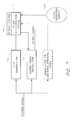
- FIG. 7illustrates an enhanced frequency estimator to provide adaptive frequency estimation (phase reconstruction) such as in the phase/frequency estimator 126 of FIG. 1 .
- phase reconstructionphase reconstruction
- FIG. 7there is demodulator 710 provided for a pilot signal and demodulator 712 provided for a desired signal.
- a phase reconstruction block 714provides phase estimation for the desired signal. Accordingly, an output of the phase reconstruction block 714 provides an input to the desired signal demodulator 712 .
- the incoming signal(after digital conversion in the present embodiment), provides an input to both the pilot demodulator 710 and the desired signal demodulator 712 .
- the phase reconstruction module 714receives input from the pilot demodulator 710 and from the signal properties module 130 (see FIG. 1 ).
- the signal properties module 130provides signals to a dynamic phase reconstruction control module 716 which forms part of the phase reconstruction module 714 .
- the dynamic phase reconstruction control module 716reacts to information from the signal properties module 130 and from the pilot demodulator 710 to dynamically control the phase reconstruction module 714 to accommodate changing signal conditions. More specifically, the phase reconstruction module operations can be adaptively controlled to change operations based on the particular signal properties at the time.
- a phase reconstruction schemecan be very important because a small error in the estimated phase can result in a large loss for the desired signal.
- existing systemsutilize the pilot signal which is transmitted at a higher power without full spreading codes so that it is much easier to demodulate. Accordingly, the demodulation allows determination of the phase of the incoming signal. Because the pilot signal and the desired signal are transmitted together, they experience similar or identical paths and interference to the receiver. During periods of high signal dynamics and multi-path components, frequency estimation becomes an important function of the system in order to avoid significant signal losses.
- the frequency estimation algorithm, precision, or active periodsmay be controlled. More specifically, any one or more of the following parameters could be included in selecting two or more algorithms which can be selected based upon the pilot demodulation information or the pilot demodulation together with the signal properties module information.
- the processing ratemay be increased or decreased. Such increase or decrease may be based on power level rather than tracking performance.
- the phase reconstruction filter 714may actually be deactivated and activated only a few to several times a second during periods of high signal strength and low signal dynamics and fading. However, during high signal dynamics, where the signal may have multi-path components and the phase is changing rapidly, the filter may run constantly. In addition or alternatively, the precision of the phase reconstruction filter 714 can be modified.
- the precisioncan be changed from 16-bit to 8-bit in one embodiment.
- the actual filter typecould be changed. For instance, a FIR filter, IIR filter, sliding window filter, or other type of filter could be selected based upon the signal characteristics.
- the signal properties module 130could play a significant role in the phase reconstruction decisions.
- Conventional designstypically involve using the pilot signal to determine frequency estimation.
- the pilotis easy to demodulate because of its high power and lack of full spreading codes.
- each base stationmay have many desired signals, each with its own spreading code transmitted in a particular direction from the base station.
- Typical base stations in spread spectrum systemsmay have three different directional sections, each which can have 10 to 20 signals with spreading codes (such as Walsh codes) for each signal.
- the signal from the base stationincludes a pilot plus several desired signals using several corresponding spreading codes.
- each mobile sitedemodulates the data resulting only from its own spreading code.
- the present embodimentalso involves utilizing the other spread spectrum signals not intended for the particular receiver in determining the phase reconstruction.
- the demodulated desired signal for other userscan be used for tracking the phase, and, the tracking can be improved.
- the additional demodulationrequires additional power; however, in periods of high signal dynamics, such increase in processing may be required in order to maintain a signal for the particular user in question.
- power saving featuresare integrated with a receiver operating in accordance with Global System for Mobile Communications (GSM).
- GSMGlobal System for Mobile Communications
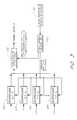
- FIG. 6illustrates a typical Global System for Mobile Communication (GSM) demodulator.
- Input lines carrying baseband I (in-phase) and Q (quadrature-phase) dataconnect to an automatic gain control module 610 and a signal level estimator 612 .
- the output of the signal level estimator 612connects to the AGC module 610 .
- the output of the AGC module 610connects to a cross-correlator 614 .
- the cross-correlator's outputconnects to each of a matched filter 617 , a matched filter extractor 618 , and a timing recovery unit 620 .
- the output of the matched filter extractor 618feeds directly into the matched filter 617 .
- the output of the matched filter 617 and the timing recovery unit 620both connect to a Maximum Likelihood Sequence Estimation (MLSE) detector 622 .
- MBEMaximum Likelihood Sequence Estimation
- the MLSE detector 622couples to the input of a decryption unit 624 and the output of the decryption unit feeds into a deleaver 626 .
- the deleaver 626outputs data to a convolutional decoder 630 .
- the convolutional decoder 630in turn connects to a block decoder 632 .
- the block decoder 632provides output on a data out line.
- the automatic gain control module 610adjusts the input signal level of the baseband I and Q data (hereinafter signal) for optimal performance during the subsequent demodulation operations as well understood in the art.
- the incoming signalalso enters a signal level estimator 612 that estimates the power level of the incoming signal. Estimating the signal power level serves two purposes; first, a GSM communication system adapts its performance based on the strength of the received signal at each of the mobile stations; and second, the receiver adjusts the gain of the input signal for subsequent demodulation processes. Accordingly, the modulator provides the output of the signal level estimator 612 to the AGC module 610 so that the gain of signal may be adjusted appropriately.
- the cross-correlator 614compares the received data to a known training sequence or a training sequence included mid-sample in the received data burst.
- the cross-correlatorlocates the beginning of each burst of data using the known 26 symbols located at the center of each burst. As known in the art, bursts are sent in a generally 0.5 millisecond time frame followed by 4.5 millisecond pause.
- the cross-correlator, having located or correlated the known 26 symbolsis able to locate the beginning of the data transmission.
- the matched filter extractor 618models an ideal matched filter to reverse the effects of the transmission channel and any inter-symbol interference introduced by the pulse shape.
- the timing recovery unit 620determines the proper timing of the incoming signal to locate the center of the burst which in-turn allows the receiver to correctly separate and demodulate the individual symbols.
- the next phase of the demodulation processcomprises MLSE detection.
- the MLSE detector 622performs a sophisticated detection algorithm that declares each received symbol to be a 1 or 0 and provides a measure of the certainty of each binary decision.
- the algorithms of the MLSE detector 622employ a dynamic programming model to simultaneously demodulate an entire half-burst (typically 58 bits) of data. While certain advantages exist in performing demodulation over the half-burst instead on a symbol-by-symbol bases, half-burst demodulation consumes a significant amount of power during operation.
- the signalAfter MLSE detection, the signal enters a decryption unit 624 to reverse the anti-eavesdropping measures undertaken by the transmitter.
- the signalenters the deleaver 626 , wherein the transmitted bits are dispersed over several time division multiple access (TDMA) bursts to provide robustness in the presence of fading.
- TDMAtime division multiple access
- the deleaver 626rearranges the received bits into message blocks i.e. into the original order existing prior to transmission.
- the output of the deleaver 626progresses to the input of the convolutional decoder 630 .
- the convolutional decoder 630performs convolutional decoding on the received data.
- Convolutional coding and decodingprovides means to detect and correct data errors introduced during transmission.
- convolutional codingadds coding to the data so that the convolutional decoder may accurately reconstruct the transmitted data, even if some of the data bits become corrupted during transmission.
- Block codingprovides redundancy, typically parity bits. These parity bits are typically often transmitted at the end of a sequence of data bits so that upon receipt by the receiver, the block decoder 632 may perform reverse block coding to determine if errors exist in the data stream.
- the signalexits the block decoder 632 for further processing in other parts of the receiver, such as a vocoder (not shown).
- the receivercomprises a digital signal processor (DSP) coded implementation of a GSM receiver.
- DSPdigital signal processor
- the inventorsrecognize that the most complex and power consuming operation is typically the MLSE detection algorithm of the MLSE detector 622 .
- the MLSE detectionmay comprise up to 50% of the complexity in relation to total DSP operations. While the advantages of the MLSE detector are worthy of its power needs during periods of poor signal quality, the MLSE detector needlessly consumes power when the signal is robust.
- Cross-correlator 614Another very complex and power consuming component is the cross-correlator 614 because it operates over a broad range of delays to correctly locate the center of the data burst.
- Cross-correlation in DSP based implementationsmay comprise up to 30% of the total DSP operations.
- a GSM receiveris configured to eliminate a substantial portion of the computational requirements of the receiver by monitoring the timing recovery unit 620 for rapid movement from center on a burst-by-burst basis.
- the receiverwould also include a cross-correlator controller 616 .
- the cross-correlator controller 616connects to the cross-correlator and the timing recovery unit.
- the cross-correlator controller 616obtains data from the timing recovery unit 620 and depending on the timing of the incoming signal, changes the operation of the cross-correlator accordingly.
- the cross-correlator controller 616instructs the cross-correlator 614 to operate over a more narrow range of delays.
- the cross-correlator 614may operate over ⁇ 5 data symbols. Under ideal situations, such as when the burst center is generally stable, performing cross-correlation over ⁇ 2 symbols may be adequate.
- the cross-correlatorcan anticipate little change in burst center and reduce computational complexity such as, for example, evaluating fewer symbols. Reducing the computational complexity and duration of the cross-correlator 614 reduces the power consumption of the receiver which, in turn, extends battery life.
- the cross-correlator controller 616instructs the cross-correlator 614 to resume operation over a broader range of delays. In this fashion, the cross-correlator controller 616 adjusts the operation of the cross-correlator 614 to save power during periods when the signal is stable without degrading signal quality.
- the receiverincludes a MLSE controller 621 connected to the MLSE detector 622 , the matched filter 617 , and the output of the signal level estimator 612 .
- the MLSE controllerreceives input from the matched filter 616 and the signal level estimator 612 .
- the MLSE controller 621monitors both the signal level of an incoming transmission and the response to the matched filter 617 . If the incoming signal level is high and the response to the match filter 617 indicates that the signal is arriving over a generally clear channel, then the receiver suspends operation of the complicated MLSE detector 622 , and instead implements a simple bit-by-bit Minimum Shift Keying (MSK) demodulator.
- MSKMinimum Shift Keying
- MSK demodulatorsare known by those of skill in the art, and require a trivial amount of computational resources, and thus battery power, in relation to the MLSE algorithms of the MLSE detector 622 due to their operation on a bit-by-bit basis instead of the typical 58 bit delay of the MLSE detector 622 .
- a receiver adopting MSK demodulation over MLSE algorithmsconsumes less power than a receiver utilizing only MLSE detection algorithms.
- the power intensive MLSE detector operationmay be suspended and replaced with bit-by-bit MSK demodulation.
- the MLSE controller 621suspends operation of the bit-by-bit MSK demodulator and resumes operation of the MLSE algorithms. In this fashion, the MLSE controller 621 reduces power consumption of the receiver without sacrificing audio quality.
- the signal level estimator and the match filterare used to determine the signal quality. Other quality measurements such as automatic gain control could be used to indicate the receiver algorithm which will be implemented for the remainder of the receiver.
Landscapes
- Engineering & Computer Science (AREA)
- Computer Networks & Wireless Communication (AREA)
- Signal Processing (AREA)
- Mobile Radio Communication Systems (AREA)
- Circuits Of Receivers In General (AREA)
- Noise Elimination (AREA)
- Input Circuits Of Receivers And Coupling Of Receivers And Audio Equipment (AREA)
- Telephone Function (AREA)
Abstract
Description
Claims (15)
Priority Applications (11)
| Application Number | Priority Date | Filing Date | Title |
|---|---|---|---|
| US09/163,797US6693953B2 (en) | 1998-09-30 | 1998-09-30 | Adaptive wireless communication receiver |
| EP99948419AEP1118178B1 (en) | 1998-09-30 | 1999-09-23 | Adaptive wireless communication receiver |
| AT99948419TATE276611T1 (en) | 1998-09-30 | 1999-09-23 | ADAPTIVE RECEIVER FOR WIRELESS COMMUNICATIONS |
| DE69920244TDE69920244T2 (en) | 1998-09-30 | 1999-09-23 | Adaptive receiver for wireless communication |
| AT01110971TATE288641T1 (en) | 1998-09-30 | 1999-09-23 | ADAPTIVE RECEIVER FOR WIRELESS COMMUNICATIONS |
| DE69923602TDE69923602T2 (en) | 1998-09-30 | 1999-09-23 | Adaptive receiver for wireless communication |
| EP01110972AEP1160993B1 (en) | 1998-09-30 | 1999-09-23 | Adaptive wireless communication receiver |
| PCT/US1999/022080WO2000019644A1 (en) | 1998-09-30 | 1999-09-23 | Adaptive wireless communication receiver |
| DE69925314TDE69925314T2 (en) | 1998-09-30 | 1999-09-23 | Adaptive receiver for wireless communication |
| AT01110972TATE295634T1 (en) | 1998-09-30 | 1999-09-23 | ADAPTIVE RECEIVER FOR WIRELESS COMMUNICATIONS |
| EP01110971AEP1158705B1 (en) | 1998-09-30 | 1999-09-23 | Adaptive wireless communication receiver |
Applications Claiming Priority (1)
| Application Number | Priority Date | Filing Date | Title |
|---|---|---|---|
| US09/163,797US6693953B2 (en) | 1998-09-30 | 1998-09-30 | Adaptive wireless communication receiver |
Publications (2)
| Publication Number | Publication Date |
|---|---|
| US20030058929A1 US20030058929A1 (en) | 2003-03-27 |
| US6693953B2true US6693953B2 (en) | 2004-02-17 |
Family
ID=22591612
Family Applications (1)
| Application Number | Title | Priority Date | Filing Date |
|---|---|---|---|
| US09/163,797Expired - Fee RelatedUS6693953B2 (en) | 1998-09-30 | 1998-09-30 | Adaptive wireless communication receiver |
Country Status (5)
| Country | Link |
|---|---|
| US (1) | US6693953B2 (en) |
| EP (3) | EP1160993B1 (en) |
| AT (3) | ATE295634T1 (en) |
| DE (3) | DE69923602T2 (en) |
| WO (1) | WO2000019644A1 (en) |
Cited By (31)
| Publication number | Priority date | Publication date | Assignee | Title |
|---|---|---|---|---|
| US20020122500A1 (en)* | 2001-02-07 | 2002-09-05 | Isao Takeuchi | Transmitting apparatus and method, receiving apparatus and method, and transmitting and receiving apparatus and method |
| US20030194993A1 (en)* | 1997-08-04 | 2003-10-16 | Mundi Fomukong | Location reporting satellite paging system with optional blocking of location reporting |
| US20030219066A1 (en)* | 2001-05-18 | 2003-11-27 | Charles Abraham, Serge De La Porte | Method and apparatus for performing signal correlation |
| US20040077365A1 (en)* | 2001-05-18 | 2004-04-22 | Global Locate Inc. | Apparatus for computing signal correlation at multiple resolutions |
| US20040141549A1 (en)* | 2001-05-18 | 2004-07-22 | Charles Abraham | Method and apparatus for performing signal correlation using historical correlation data |
| US20050025267A1 (en)* | 2003-03-03 | 2005-02-03 | Interdigital Technology Corporation | Reduced complexity sliding window based equalizer |
| US20050031024A1 (en)* | 2003-03-03 | 2005-02-10 | Interdigital Technology Corporation | Reduced complexity sliding window based equalizer |
| US7010073B2 (en)* | 2001-01-19 | 2006-03-07 | Qualcomm, Incorporated | Delay lock loops for wireless communication systems |
| US20060114970A1 (en)* | 2001-05-18 | 2006-06-01 | Global Locate, Inc. | Method and apparatus for performing signal correlation at multiple resolutions to mitigate multipath interference |
| US7079569B1 (en)* | 1999-09-24 | 2006-07-18 | Nec Corporation | Search method in CDMA mobile communication receiving system and receiving device |
| US20060203887A1 (en)* | 2003-08-06 | 2006-09-14 | Koninklijke Philips Electronics N.V. | Method of processing a sampled spread spectrum signal stream |
| US20060209935A1 (en)* | 2001-05-18 | 2006-09-21 | Global Locate, Inc. | Method and apparatus for performing signal processing using historical correlation data |
| US20060215590A1 (en)* | 2005-03-24 | 2006-09-28 | Siport, Inc. | Low power digital media broadcast receiver with time division |
| US20060287009A1 (en)* | 2005-06-16 | 2006-12-21 | Siport, Inc. | Systems and methods for dynamically controlling a tuner |
| US20070015460A1 (en)* | 2005-06-22 | 2007-01-18 | Karabinis Peter D | Systems and methods of waveform and/or information splitting for wireless transmission of information to one or more radioterminals over a plurality of transmission paths and/or system elements |
| US20070064839A1 (en)* | 2005-05-03 | 2007-03-22 | Sirf Technology, Inc. | Power Management in Digital Receivers |
| US20070218936A1 (en)* | 2005-03-24 | 2007-09-20 | Siport, Inc. | Systems and methods for saving power in a digital broadcast receiver |
| US20070291672A1 (en)* | 2006-06-08 | 2007-12-20 | Yuval Kochman | Reducing power consumption in a receiver |
| US20080291857A1 (en)* | 2007-05-25 | 2008-11-27 | Siport, Inc. | Timeslot scheduling in digital audio and hybrid audio radio systems |
| US20090135035A1 (en)* | 2004-10-26 | 2009-05-28 | Koninklijke Philips Electronics N.V. | Adapting filter to detected interference level |
| US20100056058A1 (en)* | 2008-08-28 | 2010-03-04 | Tinsley Keith R | Method and apparatus for mitigating radio frequency interference in a platform |
| US20100052986A1 (en)* | 2008-09-03 | 2010-03-04 | Harris Corporation | Coherent combining for widely-separated apertures |
| US20100189203A1 (en)* | 2009-01-29 | 2010-07-29 | Telefonaktiebolaget Lm Ericsson (Publ) | Automatic Gain Control Based on Bandwidth and Delay Spread |
| US20100272161A1 (en)* | 2003-10-22 | 2010-10-28 | Jason Goldberg | Method and apparatus for performing frequency synchronization |
| US20100330900A1 (en)* | 2009-05-04 | 2010-12-30 | Oren Arad | Digital radio broadcast transmission using a table of contents |
| US8335484B1 (en)* | 2005-07-29 | 2012-12-18 | Siport, Inc. | Systems and methods for dynamically controlling an analog-to-digital converter |
| US8489053B2 (en) | 2011-01-16 | 2013-07-16 | Siport, Inc. | Compensation of local oscillator phase jitter |
| US20130222198A1 (en)* | 2012-02-28 | 2013-08-29 | Maruwa, Co., Ltd | Antenna module, magnetic material sheet and double-sided adhesive spacer, and methods for the manufacture thereof |
| US20150023237A1 (en)* | 2009-04-23 | 2015-01-22 | Maxlinear, Inc. | Channel-sensitive power control |
| US9712348B1 (en)* | 2016-01-15 | 2017-07-18 | Avago Technologies General Ip (Singapore) Pte. Ltd. | System, device, and method for shaping transmit noise |
| US9985671B2 (en)* | 2016-01-15 | 2018-05-29 | Avago Technologies General Ip (Singapore) Pte. Ltd. | System, device, and method for improving radio performance |
Families Citing this family (41)
| Publication number | Priority date | Publication date | Assignee | Title |
|---|---|---|---|---|
| US7545854B1 (en) | 1998-09-01 | 2009-06-09 | Sirf Technology, Inc. | Doppler corrected spread spectrum matched filter |
| US6693953B2 (en) | 1998-09-30 | 2004-02-17 | Skyworks Solutions, Inc. | Adaptive wireless communication receiver |
| US6775260B1 (en)* | 1999-02-25 | 2004-08-10 | Texas Instruments Incorporated | Space time transmit diversity for TDD/WCDMA systems |
| US6304216B1 (en) | 1999-03-30 | 2001-10-16 | Conexant Systems, Inc. | Signal detector employing correlation analysis of non-uniform and disjoint sample segments |
| US6115406A (en)* | 1999-09-10 | 2000-09-05 | Interdigital Technology Corporation | Transmission using an antenna array in a CDMA communication system |
| US6278726B1 (en)* | 1999-09-10 | 2001-08-21 | Interdigital Technology Corporation | Interference cancellation in a spread spectrum communication system |
| US6931055B1 (en) | 2000-04-18 | 2005-08-16 | Sirf Technology, Inc. | Signal detector employing a doppler phase correction system |
| US6952440B1 (en) | 2000-04-18 | 2005-10-04 | Sirf Technology, Inc. | Signal detector employing a Doppler phase correction system |
| US6714158B1 (en) | 2000-04-18 | 2004-03-30 | Sirf Technology, Inc. | Method and system for data detection in a global positioning system satellite receiver |
| ATE326821T1 (en)* | 2000-07-10 | 2006-06-15 | Interdigital Tech Corp | CODE POWER MEASUREMENT FOR DYNAMIC CHANNEL APPLICATION |
| US7110437B2 (en) | 2001-03-14 | 2006-09-19 | Mercury Computer Systems, Inc. | Wireless communications systems and methods for direct memory access and buffering of digital signals for multiple user detection |
| US7376175B2 (en)* | 2001-03-14 | 2008-05-20 | Mercury Computer Systems, Inc. | Wireless communications systems and methods for cache enabled multiple processor based multiple user detection |
| JP2002290279A (en)* | 2001-03-28 | 2002-10-04 | Toshiba Corp | Synchronous tracking device and wireless communication terminal |
| US7177369B2 (en)* | 2001-04-27 | 2007-02-13 | Vivato, Inc. | Multipath communication methods and apparatuses |
| US6856646B2 (en)* | 2002-03-19 | 2005-02-15 | Nokia Corporation | T-spaced equalization for 1xEV systems |
| FR2851098B1 (en)* | 2003-02-10 | 2006-08-25 | Nortel Networks Ltd | METHOD OF PROCESSING A SIGNAL BY A RADIO RECEIVER AND RADIO RECEIVER FOR IMPLEMENTING THE METHOD |
| US7437135B2 (en)* | 2003-10-30 | 2008-10-14 | Interdigital Technology Corporation | Joint channel equalizer interference canceller advanced receiver |
| US8036327B2 (en)* | 2003-12-19 | 2011-10-11 | Telefonaktiebolaget L M Ericsson (Publ) | Adaptive channel measurement reporting |
| US7400692B2 (en) | 2004-01-14 | 2008-07-15 | Interdigital Technology Corporation | Telescoping window based equalization |
| JP4443269B2 (en)* | 2004-03-08 | 2010-03-31 | 富士通テン株式会社 | Evaluation method for spread spectrum radar apparatus and spread spectrum radar apparatus |
| FR2895606A1 (en)* | 2005-12-23 | 2007-06-29 | France Telecom | Communication device for receiving signal transmitted by base station, has configuration unit configuring receiver to process samples when variable representative of performance of receiver is greater than/equal to target performance value |
| US7852325B2 (en)* | 2007-01-05 | 2010-12-14 | Apple Inc. | RF pulse synchronization for data acquisition operations |
| US8050641B2 (en) | 2007-01-25 | 2011-11-01 | Texas Instruments Incorporated | Limiting the power consumption of a wireless electronic system |
| US7813371B2 (en)* | 2007-03-21 | 2010-10-12 | Kapsch Trafficcom Ag | System and method for short range communication using adaptive channel intervals |
| WO2008117130A1 (en)* | 2007-03-27 | 2008-10-02 | Freescale Semiconductor, Inc. | Method and apparatus for varying a dynamic range |
| US8982744B2 (en)* | 2007-06-06 | 2015-03-17 | Broadcom Corporation | Method and system for a subband acoustic echo canceller with integrated voice activity detection |
| US20080310485A1 (en) | 2007-06-15 | 2008-12-18 | Qualcomm Incorporated | System and methods for controlling modem hardware |
| US8090377B2 (en)* | 2007-06-26 | 2012-01-03 | Cisco Technology, Inc. | Method and system for using signal quality information |
| US7715669B2 (en)* | 2007-10-17 | 2010-05-11 | Avago Technologies Fiber Ip (Singapore) Pte. Ltd. | Fiber optic link, a transceiver for use in the link, and methods for designing and constructing fiber optic links and transceivers |
| US8418046B2 (en)* | 2008-02-13 | 2013-04-09 | Apple Inc. | Data signal handling circuitry and methods with error analysis capabilities |
| US8212720B2 (en)* | 2008-09-24 | 2012-07-03 | Texas Instruments Incorporated | Detecting lack of movement to aid GNSS receivers |
| EP2385440A1 (en)* | 2010-05-07 | 2011-11-09 | ST-Ericsson SA | Method and system for controlling the operation of an electronic device |
| EP2439678B1 (en)* | 2010-10-05 | 2013-05-01 | Nxp B.V. | Smart card |
| DE102010056080A1 (en)* | 2010-12-23 | 2012-06-28 | Hydrometer Electronic Gmbh | Radio receiver and method for its operation |
| US8903028B2 (en)* | 2012-09-20 | 2014-12-02 | Novelsat Ltd. | Timing recovery for low roll-off factor signals |
| US9442597B2 (en) | 2012-10-19 | 2016-09-13 | Apple Inc. | Sensor-based ESD detection |
| US8953711B2 (en) | 2013-06-04 | 2015-02-10 | Qualcomm Incorporated | Configurable pre-emphasis component for transmission circuitry |
| US9100233B2 (en)* | 2013-12-04 | 2015-08-04 | Realtek Semiconductor Corp. | Binary signal detection based on non-uniform ADC |
| US9811204B2 (en) | 2014-06-23 | 2017-11-07 | Apple Inc. | Time multiplexed touch detection and power charging |
| DE102017116273A1 (en)* | 2017-03-30 | 2018-10-04 | Riedel Communications International GmbH | Network device for an intercom network |
| CN113133091B (en)* | 2019-12-31 | 2022-07-22 | 华为技术有限公司 | Signal receiving method and terminal device |
Citations (158)
| Publication number | Priority date | Publication date | Assignee | Title |
|---|---|---|---|---|
| US3604911A (en) | 1969-05-15 | 1971-09-14 | Sylvania Electric Prod | Serial-parallel digital correlator |
| US3975628A (en) | 1975-04-02 | 1976-08-17 | Hughes Aircraft Company | Optical heterodyne receiver with phase or frequency lock |
| US4426712A (en) | 1981-05-22 | 1984-01-17 | Massachusetts Institute Of Technology | Correlation system for global position receiver |
| US4445118A (en) | 1981-05-22 | 1984-04-24 | The United States Of America As Represented By The Administrator Of The National Aeronautics And Space Administration | Navigation system and method |
| US4463357A (en) | 1981-11-17 | 1984-07-31 | The United States Of America As Represented By The Administrator Of The National Aeronautics And Space Administration | Method and apparatus for calibrating the ionosphere and application to surveillance of geophysical events |
| US4578678A (en) | 1983-11-14 | 1986-03-25 | The United States Of America As Represented By The United States National Aeronautics And Space Administration | High dynamic global positioning system receiver |
| US4667203A (en) | 1982-03-01 | 1987-05-19 | Aero Service Div, Western Geophysical | Method and system for determining position using signals from satellites |
| US4701934A (en) | 1985-09-03 | 1987-10-20 | Motorola, Inc. | Method of doppler searching in a digital GPS receiver |
| US4754465A (en) | 1984-05-07 | 1988-06-28 | Trimble Navigation, Inc. | Global positioning system course acquisition code receiver |
| US4785463A (en) | 1985-09-03 | 1988-11-15 | Motorola, Inc. | Digital global positioning system receiver |
| US4809005A (en) | 1982-03-01 | 1989-02-28 | Western Atlas International, Inc. | Multi-antenna gas receiver for seismic survey vessels |
| US4821294A (en) | 1987-07-08 | 1989-04-11 | California Institute Of Technology | Digital signal processor and processing method for GPS receivers |
| US4890233A (en) | 1986-10-27 | 1989-12-26 | Pioneer Electronic Corporation | Vehicle bearing detection and data processing methods applicable to vehicle navigation system |
| US4894842A (en) | 1987-10-15 | 1990-01-16 | The Charles Stark Draper Laboratory, Inc. | Precorrelation digital spread spectrum receiver |
| US4894662A (en) | 1982-03-01 | 1990-01-16 | Western Atlas International, Inc. | Method and system for determining position on a moving platform, such as a ship, using signals from GPS satellites |
| US4992720A (en) | 1988-01-29 | 1991-02-12 | Nec Corporation | Charge control circuit for cordless telephone system |
| US4998111A (en) | 1989-11-27 | 1991-03-05 | Motorola, Inc. | CPS transform correlation receiver and method |
| US5014066A (en) | 1982-03-01 | 1991-05-07 | Western Atlas International, Inc. | System for simultaneously deriving position information from a plurality of satellite transmissions |
| US5018088A (en) | 1989-10-02 | 1991-05-21 | The Johns Hopkins University | Adaptive locally-optimum detection signal processor and processing methods |
| US5036329A (en) | 1989-11-22 | 1991-07-30 | Pioneer Electronic Corporation | GPS satellite signal tracking method for GPS receivers |
| US5043736A (en) | 1990-07-27 | 1991-08-27 | Cae-Link Corporation | Cellular position locating system |
| US5108334A (en) | 1989-06-01 | 1992-04-28 | Trimble Navigation, Ltd. | Dual down conversion GPS receiver with single local oscillator |
| US5148042A (en) | 1989-12-29 | 1992-09-15 | Kabushiki Kaisha Toshiba | Small electronic device capable of switching batteries by releasing a battery locking mechanism |
| US5153591A (en) | 1988-07-05 | 1992-10-06 | British Telecommunications Public Limited Company | Method and apparatus for encoding, decoding and transmitting data in compressed form |
| US5179724A (en) | 1991-01-15 | 1993-01-12 | Ericsson G.E. Mobile Communications Holding Inc. | Conserving power in hand held mobile telephones during a receiving mode of operation |
| US5202829A (en) | 1991-06-10 | 1993-04-13 | Trimble Navigation Limited | Exploration system and method for high-accuracy and high-confidence level relative position and velocity determinations |
| US5225842A (en) | 1991-05-09 | 1993-07-06 | Navsys Corporation | Vehicle tracking system employing global positioning system (gps) satellites |
| US5253268A (en) | 1990-05-24 | 1993-10-12 | Cylink Corporation | Method and apparatus for the correlation of sample bits of spread spectrum radio signals |
| US5276765A (en) | 1988-03-11 | 1994-01-04 | British Telecommunications Public Limited Company | Voice activity detection |
| US5293398A (en) | 1991-12-13 | 1994-03-08 | Clarion Co., Ltd. | Digital matched filter |
| US5293170A (en) | 1991-04-10 | 1994-03-08 | Ashtech Inc. | Global positioning system receiver digital processing technique |
| US5297097A (en) | 1988-06-17 | 1994-03-22 | Hitachi Ltd. | Large scale integrated circuit for low voltage operation |
| US5311195A (en) | 1991-08-30 | 1994-05-10 | Etak, Inc. | Combined relative and absolute positioning method and apparatus |
| US5323164A (en) | 1992-03-16 | 1994-06-21 | Pioneer Electronic Corporation | Satellite radio wave capturing method for a global positioning system (GPS) receiver |
| US5343209A (en) | 1992-05-07 | 1994-08-30 | Sennott James W | Navigation receiver with coupled signal-tracking channels |
| US5345244A (en) | 1993-01-12 | 1994-09-06 | Trimble Navigation Limited | Cordless SPS smart antenna device |
| US5347536A (en) | 1993-03-17 | 1994-09-13 | The United States Of America As Represented By The Administrator Of The National Aeronautics And Space Administration | Multipath noise reduction for spread spectrum signals |
| US5352970A (en) | 1992-11-25 | 1994-10-04 | Benchmarq Microelectronics, Inc. | Power resource management system |
| US5363030A (en) | 1991-09-16 | 1994-11-08 | Motorola, Inc. | Battery having a transistor switch for supplying energy |
| US5378155A (en) | 1992-07-21 | 1995-01-03 | Teledyne, Inc. | Combat training system and method including jamming |
| US5379224A (en) | 1991-11-29 | 1995-01-03 | Navsys Corporation | GPS tracking system |
| EP0639901A2 (en) | 1993-08-20 | 1995-02-22 | Hitachi, Ltd. | Radio communication apparatus with circuit for field strength determination |
| US5396515A (en) | 1989-08-07 | 1995-03-07 | Omnipoint Corporation | Asymmetric spread spectrum correlator |
| US5402347A (en) | 1993-07-22 | 1995-03-28 | Trimble Navigation Limited | Satellite search methods for improving time to first fix in a GPS receiver |
| US5402346A (en) | 1992-09-15 | 1995-03-28 | Thomson Csf | System for the calculation of at least one vehicular traffic check parameter |
| US5410747A (en) | 1990-07-31 | 1995-04-25 | Nec Corporation | Dual conversion transmitter |
| US5416712A (en) | 1993-05-28 | 1995-05-16 | Trimble Navigation Limited | Position and velocity estimation system for adaptive weighting of GPS and dead-reckoning information |
| US5418818A (en) | 1992-09-22 | 1995-05-23 | Glenayre Electronics, Inc. | Digital signal processor exciter |
| US5420593A (en) | 1993-04-09 | 1995-05-30 | Trimble Navigation Limited | Method and apparatus for accelerating code correlation searches in initial acquisition and doppler and code phase in re-acquisition of GPS satellite signals |
| US5440313A (en) | 1993-05-27 | 1995-08-08 | Stellar Gps Corporation | GPS synchronized frequency/time source |
| US5450442A (en)* | 1990-11-02 | 1995-09-12 | Kabushiki Kaisha Toshiba | Digital radio telephone apparatus having an equalizer selectively employed in the apparatus |
| US5450344A (en) | 1994-04-22 | 1995-09-12 | Trimble Navigation Limited | GPS receivers with data ports for the uploading and downloading of absolute position information |
| US5498239A (en) | 1995-04-17 | 1996-03-12 | Guided Medical Systems, Inc. | Catheter placement by pressurizable tubular guiding core |
| US5504684A (en) | 1993-12-10 | 1996-04-02 | Trimble Navigation Limited | Single-chip GPS receiver digital signal processing and microcomputer |
| US5546445A (en) | 1991-12-26 | 1996-08-13 | Dennison; Everett | Cellular telephone system that uses position of a mobile unit to make call management decisions |
| US5548613A (en) | 1993-12-30 | 1996-08-20 | Nec Corporation | DS/CDMA receiver using moving-averaged pilot signals for weighting and phase rotation of orthogonal data symbol vectors |
| US5550811A (en) | 1993-12-30 | 1996-08-27 | Nec Corporation | Sync acquisition and tracking circuit for DS/CDMA receiver |
| US5568473A (en) | 1994-12-08 | 1996-10-22 | Comsat Corporation | Method and apparatus for simple and efficient interference cancellation for chip synchronized CDMA |
| US5577025A (en) | 1995-06-30 | 1996-11-19 | Qualcomm Incorporated | Signal acquisition in a multi-user communication system using multiple walsh channels |
| US5577023A (en) | 1992-12-01 | 1996-11-19 | Farallon Computing, Inc. | Method and apparatus for automatic configuration of a network connection |
| US5592173A (en) | 1994-07-18 | 1997-01-07 | Trimble Navigation, Ltd | GPS receiver having a low power standby mode |
| US5594453A (en) | 1994-11-01 | 1997-01-14 | Trimble Navigation, Ltd | GPS receiver having a rapid acquisition of GPS satellite signals |
| US5608722A (en) | 1995-04-03 | 1997-03-04 | Qualcomm Incorporated | Multi-user communication system architecture with distributed receivers |
| US5623485A (en) | 1995-02-21 | 1997-04-22 | Lucent Technologies Inc. | Dual mode code division multiple access communication system and method |
| US5625668A (en) | 1994-04-12 | 1997-04-29 | Trimble Navigation Limited | Position reporting cellular telephone |
| US5640431A (en) | 1995-03-10 | 1997-06-17 | Motorola, Inc. | Method and apparatus for offset frequency estimation for a coherent receiver |
| US5640429A (en) | 1995-01-20 | 1997-06-17 | The United States Of America As Represented By The Secretary Of The Air Force | Multichannel non-gaussian receiver and method |
| US5642377A (en) | 1995-07-25 | 1997-06-24 | Nokia Mobile Phones, Ltd. | Serial search acquisition system with adaptive threshold and optimal decision for spread spectrum systems |
| US5644591A (en) | 1994-07-29 | 1997-07-01 | Qualcomm Incorporated | Method and apparatus for performing search acquisition in a CDMA communications system |
| US5649000A (en) | 1994-11-16 | 1997-07-15 | Electronics & Telecommunications Research Institute | Method and system for providing a different frequency handoff in a CDMA cellular telephone system |
| US5650792A (en) | 1994-09-19 | 1997-07-22 | Dorne & Margolin, Inc. | Combination GPS and VHF antenna |
| US5654718A (en) | 1994-10-06 | 1997-08-05 | Garmin Corporation | GPS receiver device and method for calibrating a temperature uncompensated crystal oscillator |
| US5663734A (en) | 1995-10-09 | 1997-09-02 | Precision Tracking, Inc. | GPS receiver and method for processing GPS signals |
| US5663735A (en) | 1996-05-20 | 1997-09-02 | Trimble Navigation Limited | GPS receiver using a radio signal for improving time to first fix |
| US5684793A (en)* | 1993-06-07 | 1997-11-04 | Nokia Telecommunications Oy | Base station receiver equipment |
| EP0511741B1 (en) | 1991-03-29 | 1997-11-05 | Texas Instruments Incorporated | Enhanced L1/L2 code channel for global positioning system receivers |
| DE19726045A1 (en) | 1996-06-20 | 1998-01-08 | Nec Corp | Battery-saving radio pager for reception of variable encoding formats |
| US5722061A (en) | 1994-12-16 | 1998-02-24 | Qualcomm Incorporated | Method and apparatus for increasing receiver immunity to interference |
| US5734966A (en) | 1995-01-20 | 1998-03-31 | Diablo Research Corporation | Wireless communication system for adapting to frequency drift |
| US5734674A (en) | 1990-11-28 | 1998-03-31 | Novatel Inc. | Pseudorandom-noise receiver having automatic switching between regular and anti-jamming modes |
| US5737329A (en) | 1995-04-14 | 1998-04-07 | Kabushiki Kaisha Toshiba | Spread spectrum communication apparatus |
| US5739596A (en) | 1995-04-06 | 1998-04-14 | Seiko Epson Corporation | Power supply for an electronic device and power delivery method therefor |
| US5749067A (en) | 1993-09-14 | 1998-05-05 | British Telecommunications Public Limited Company | Voice activity detector |
| US5784695A (en) | 1996-05-14 | 1998-07-21 | Trw Inc. | Method and apparatus for handover control in a satellite based telecommunications system |
| US5786789A (en) | 1994-11-14 | 1998-07-28 | Trimble Navigation Limited | GPS and cellphone unit having add-on modules |
| US5812087A (en) | 1997-02-03 | 1998-09-22 | Snaptrack, Inc. | Method and apparatus for satellite positioning system based time measurement |
| US5825327A (en) | 1996-03-08 | 1998-10-20 | Snaptrack, Inc. | GPS receivers and garments containing GPS receivers and methods for using these GPS receivers |
| US5828694A (en) | 1996-07-01 | 1998-10-27 | Trimble Navigation Limited | Determination of multipath tracking error |
| US5832021A (en) | 1996-05-30 | 1998-11-03 | Nec Corporation | Correlation detector for use in a spread spectrum communications receiver |
| US5831574A (en) | 1996-03-08 | 1998-11-03 | Snaptrack, Inc. | Method and apparatus for determining the location of an object which may have an obstructed view of the sky |
| US5835047A (en)* | 1995-08-31 | 1998-11-10 | U.S. Philips Corporation | Folding A/D converter |
| US5841396A (en) | 1996-03-08 | 1998-11-24 | Snaptrack, Inc. | GPS receiver utilizing a communication link |
| US5845203A (en) | 1996-01-25 | 1998-12-01 | Aertis Cormmunications | Remote access application messaging wireless method |
| US5854605A (en) | 1996-07-05 | 1998-12-29 | Trimble Navigation Limited | GPS receiver using data bit timing to achieve a fast time to first fix |
| US5859840A (en)* | 1996-05-31 | 1999-01-12 | Qualcomm Incorporated | Spread spectrum communication system which defines channel groups comprising selected channels that are additional to a primary channel and transmits group messages during call set up |
| US5862465A (en) | 1996-01-29 | 1999-01-19 | Oki Electric Industry Co., Ltd. | Hysteresis-free anti-saturation circuit |
| US5867535A (en) | 1995-08-31 | 1999-02-02 | Northrop Grumman Corporation | Common transmit module for a programmable digital radio |
| US5867795A (en) | 1996-08-23 | 1999-02-02 | Motorola, Inc. | Portable electronic device with transceiver and visual image display |
| US5872540A (en) | 1997-06-26 | 1999-02-16 | Electro-Radiation Incorporated | Digital interference suppression system for radio frequency interference cancellation |
| US5877724A (en) | 1997-03-25 | 1999-03-02 | Trimble Navigation Limited | Combined position locating and cellular telephone system with a single shared microprocessor |
| US5878329A (en)* | 1990-03-19 | 1999-03-02 | Celsat America, Inc. | Power control of an integrated cellular communications system |
| US5877725A (en) | 1997-03-06 | 1999-03-02 | Trimble Navigation Limited | Wide augmentation system retrofit receiver |
| US5881371A (en) | 1995-10-27 | 1999-03-09 | Trimble Navigation Limited | Antenna switching technique for improved data throughput in communication networks |
| US5883594A (en) | 1997-02-20 | 1999-03-16 | Trimble Navigation Limited | GPS receiver using a message system for reducing power consumption |
| US5884214A (en) | 1996-09-06 | 1999-03-16 | Snaptrack, Inc. | GPS receiver and method for processing GPS signals |
| US5889474A (en) | 1992-05-18 | 1999-03-30 | Aeris Communications, Inc. | Method and apparatus for transmitting subject status information over a wireless communications network |
| US5903654A (en) | 1997-08-06 | 1999-05-11 | Rockwell Science Center, Inc. | Method and apparatus for eliminating ionospheric delay error in global positioning system signals |
| US5907809A (en) | 1994-01-11 | 1999-05-25 | Ericsson Inc. | Position determination using multiple base station signals |
| US5917444A (en) | 1995-05-22 | 1999-06-29 | Trimble Navigation Ltd. | Reduction of time to first fix in an SATPS receiver |
| US5917829A (en) | 1996-12-04 | 1999-06-29 | State Of Israel-Ministry Of Defense, Rafael - Armament Development Authority | Asynchronous CDMA decorrelating detector |
| US5920283A (en) | 1997-05-09 | 1999-07-06 | Conexant Systems, Inc. | Receiver engine for global positioning system |
| US5924024A (en) | 1996-05-15 | 1999-07-13 | Shinko Electric Industries, Co., Ltd. | Method and circuit for achieving frequency conversion |
| US5923703A (en) | 1996-05-20 | 1999-07-13 | Pon; Rayman | Variable suppression of multipath signal effects |
| US5926131A (en) | 1996-09-11 | 1999-07-20 | Seiko Instruments Inc. | GPS receiving apparatus |
| US5936572A (en) | 1994-02-04 | 1999-08-10 | Trimble Navigation Limited | Portable hybrid location determination system |
| US5943363A (en) | 1996-07-17 | 1999-08-24 | Stanford Telecommunications, Inc. | Digital spread spectrum GPS navigation receiver |
| US5945944A (en) | 1996-03-08 | 1999-08-31 | Snaptrack, Inc. | Method and apparatus for determining time for GPS receivers |
| US5956328A (en) | 1995-11-30 | 1999-09-21 | Nec Corporation | Spread spectrum communications system |
| US5963582A (en) | 1996-05-24 | 1999-10-05 | Leica Geosystems Inc. | Mitigation of multipath effects in global positioning system receivers |
| US5970084A (en) | 1996-06-13 | 1999-10-19 | Matsushita Electric Industrial Co., Ltd. | CDMA mobile communication receiving apparatus |
| US5977909A (en) | 1998-03-13 | 1999-11-02 | General Electric Company | Method and apparatus for locating an object using reduced number of GPS satellite signals or with improved accuracy |
| US5982315A (en)* | 1997-09-12 | 1999-11-09 | Qualcomm Incorporated | Multi-loop Σ Δ analog to digital converter |
| US5982324A (en) | 1998-05-14 | 1999-11-09 | Nortel Networks Corporation | Combining GPS with TOA/TDOA of cellular signals to locate terminal |
| US5987016A (en) | 1997-11-04 | 1999-11-16 | Motorola, Inc. | Method and apparatus for tracking a communication signal in a wireless communication system |
| US5991309A (en) | 1996-04-12 | 1999-11-23 | E.F. Johnson Company | Bandwidth management system for a remote repeater network |
| US5991613A (en) | 1992-10-26 | 1999-11-23 | Siemens Aktiengesellschaft | Method and arrangement for antenna selection control in a radio receiver |
| US5995537A (en) | 1996-03-22 | 1999-11-30 | Nec Corporation | Synchronism acquisition method and apparatus for correlation demodulation |
| US5999124A (en) | 1998-04-22 | 1999-12-07 | Snaptrack, Inc, | Satellite positioning system augmentation with wireless communication signals |
| US6002363A (en) | 1996-03-08 | 1999-12-14 | Snaptrack, Inc. | Combined GPS positioning system and communications system utilizing shared circuitry |
| US6002709A (en) | 1996-11-21 | 1999-12-14 | Dsp Group, Inc. | Verification of PN synchronization in a direct-sequence spread-spectrum digital communications system |
| US6002362A (en) | 1998-04-20 | 1999-12-14 | Caterpillar Inc. | Apparatus and method for receiving position and control signals by a mobile machine |
| US6009551A (en) | 1995-05-05 | 1999-12-28 | Trimble Navigation Limited | Optimum utilization of pseudorange and range rate corrections by SATPS receiver |
| US6016119A (en) | 1995-10-09 | 2000-01-18 | Snaptrack, Inc. | Method and apparatus for determining the location of an object which may have an obstructed view of the sky |
| US6023462A (en) | 1997-12-10 | 2000-02-08 | L-3 Communications Corporation | Fixed wireless loop system that ranks non-assigned PN codes to reduce interference |
| US6028901A (en)* | 1994-05-19 | 2000-02-22 | Hughes Electronics Corporation | Receiver selection based on delay spread estimation |
| US6041222A (en) | 1997-09-08 | 2000-03-21 | Ericsson Inc. | Systems and methods for sharing reference frequency signals within a wireless mobile terminal between a wireless transceiver and a global positioning system receiver |
| US6047016A (en) | 1997-06-23 | 2000-04-04 | Cellnet Data Systems, Inc. | Processing a spread spectrum signal in a frequency adjustable system |
| US6047017A (en) | 1996-04-25 | 2000-04-04 | Cahn; Charles R. | Spread spectrum receiver with multi-path cancellation |
| US6049715A (en) | 1994-06-01 | 2000-04-11 | Nortel Networks Corporation | Method and apparatus for evaluating a received signal in a wireless communication utilizing long and short term values |
| US6052405A (en)* | 1996-11-25 | 2000-04-18 | Matsushita Electric Industrial Company, Ltd. | Spread spectrum receiver for use in communication systems |
| US6061018A (en) | 1998-05-05 | 2000-05-09 | Snaptrack, Inc. | Method and system for using altitude information in a satellite positioning system |
| US6064688A (en) | 1996-08-12 | 2000-05-16 | Nec Corporation | CDMA synchronous acquisition circuit |
| US6067446A (en)* | 1996-07-11 | 2000-05-23 | Telefonaktiebolaget Lm Ericsson | Power presetting in a radio communication system |
| US6075809A (en) | 1997-01-06 | 2000-06-13 | Sony Corporation | Receiving apparatus, receiving method and terminal unit for use with radio system |
| US6104338A (en) | 1998-05-04 | 2000-08-15 | Snaptrack, Inc. | Method and apparatus for operating a satellite positioning system receiver |
| US6104340A (en) | 1995-10-09 | 2000-08-15 | Snaptrack, Inc. | GPS receiver and method for processing GPS signals |
| US6107960A (en) | 1998-01-20 | 2000-08-22 | Snaptrack, Inc. | Reducing cross-interference in a combined GPS receiver and communication system |
| US6131067A (en) | 1995-10-09 | 2000-10-10 | Snaptrack, Inc. | Client-server based remote locator device |
| US6133873A (en) | 1998-06-03 | 2000-10-17 | Krasner; Norman F. | Method and apparatus for adaptively processing GPS signals in a GPS receiver |
| US6133874A (en) | 1996-03-08 | 2000-10-17 | Snaptrack, Inc. | Method and apparatus for acquiring satellite positioning system signals |
| US6134430A (en)* | 1997-12-09 | 2000-10-17 | Younis; Saed G. | Programmable dynamic range receiver with adjustable dynamic range analog to digital converter |
| US6148044A (en)* | 1996-01-16 | 2000-11-14 | Kokusai Electric Co., Ltd. | Correlating filter and CDMA receiver |
| US6259927B1 (en)* | 1997-06-06 | 2001-07-10 | Telefonaktiebolaget Lm Ericsson | Transmit power control in a radio communication system |
| US6324207B1 (en)* | 1996-04-29 | 2001-11-27 | Golden Bridge Technology, Inc. | Handoff with closed-loop power control |
| US6407689B1 (en)* | 2000-11-01 | 2002-06-18 | Qualcomm, Incorporated | Method and apparatus for controlling stages of a multi-stage circuit |
| EP1158705A3 (en) | 1998-09-30 | 2003-03-05 | Conexant Systems, Inc. | Adaptive wireless communication receiver |
| US6532370B1 (en)* | 1999-09-30 | 2003-03-11 | Skyworks Solutions, Inc. | Cellular handset with adjustable analog to digital conversion |
| US6538592B1 (en)* | 2001-09-24 | 2003-03-25 | Lsi Logic Corporation | Variable dynamic range analog-to-digital converter |
Family Cites Families (2)
| Publication number | Priority date | Publication date | Assignee | Title |
|---|---|---|---|---|
| JPH0865205A (en)* | 1994-08-24 | 1996-03-08 | Matsushita Electric Ind Co Ltd | CDMA mobile communication device |
| JP3428629B2 (en)* | 1999-03-26 | 2003-07-22 | 日本電気株式会社 | Mobile phone device and power control method thereof |
- 1998
- 1998-09-30USUS09/163,797patent/US6693953B2/ennot_activeExpired - Fee Related
- 1999
- 1999-09-23ATAT01110972Tpatent/ATE295634T1/ennot_activeIP Right Cessation
- 1999-09-23DEDE69923602Tpatent/DE69923602T2/ennot_activeExpired - Lifetime
- 1999-09-23ATAT99948419Tpatent/ATE276611T1/ennot_activeIP Right Cessation
- 1999-09-23DEDE69925314Tpatent/DE69925314T2/ennot_activeExpired - Lifetime
- 1999-09-23WOPCT/US1999/022080patent/WO2000019644A1/enactiveIP Right Grant
- 1999-09-23EPEP01110972Apatent/EP1160993B1/ennot_activeExpired - Lifetime
- 1999-09-23EPEP99948419Apatent/EP1118178B1/ennot_activeExpired - Lifetime
- 1999-09-23ATAT01110971Tpatent/ATE288641T1/ennot_activeIP Right Cessation
- 1999-09-23EPEP01110971Apatent/EP1158705B1/ennot_activeExpired - Lifetime
- 1999-09-23DEDE69920244Tpatent/DE69920244T2/ennot_activeExpired - Lifetime
Patent Citations (169)
| Publication number | Priority date | Publication date | Assignee | Title |
|---|---|---|---|---|
| US3604911A (en) | 1969-05-15 | 1971-09-14 | Sylvania Electric Prod | Serial-parallel digital correlator |
| US3975628A (en) | 1975-04-02 | 1976-08-17 | Hughes Aircraft Company | Optical heterodyne receiver with phase or frequency lock |
| US4426712A (en) | 1981-05-22 | 1984-01-17 | Massachusetts Institute Of Technology | Correlation system for global position receiver |
| US4445118A (en) | 1981-05-22 | 1984-04-24 | The United States Of America As Represented By The Administrator Of The National Aeronautics And Space Administration | Navigation system and method |
| US4463357A (en) | 1981-11-17 | 1984-07-31 | The United States Of America As Represented By The Administrator Of The National Aeronautics And Space Administration | Method and apparatus for calibrating the ionosphere and application to surveillance of geophysical events |
| US4894662A (en) | 1982-03-01 | 1990-01-16 | Western Atlas International, Inc. | Method and system for determining position on a moving platform, such as a ship, using signals from GPS satellites |
| US4667203A (en) | 1982-03-01 | 1987-05-19 | Aero Service Div, Western Geophysical | Method and system for determining position using signals from satellites |
| US5014066B1 (en) | 1982-03-01 | 1996-01-30 | Western Atlas Int Inc | System for simultaneously deriving position information from a plurality of satellite transmissions |
| US4809005A (en) | 1982-03-01 | 1989-02-28 | Western Atlas International, Inc. | Multi-antenna gas receiver for seismic survey vessels |
| US5014066A (en) | 1982-03-01 | 1991-05-07 | Western Atlas International, Inc. | System for simultaneously deriving position information from a plurality of satellite transmissions |
| US4578678A (en) | 1983-11-14 | 1986-03-25 | The United States Of America As Represented By The United States National Aeronautics And Space Administration | High dynamic global positioning system receiver |
| US4754465A (en) | 1984-05-07 | 1988-06-28 | Trimble Navigation, Inc. | Global positioning system course acquisition code receiver |
| US4701934A (en) | 1985-09-03 | 1987-10-20 | Motorola, Inc. | Method of doppler searching in a digital GPS receiver |
| US4785463A (en) | 1985-09-03 | 1988-11-15 | Motorola, Inc. | Digital global positioning system receiver |
| US4890233A (en) | 1986-10-27 | 1989-12-26 | Pioneer Electronic Corporation | Vehicle bearing detection and data processing methods applicable to vehicle navigation system |
| US4821294A (en) | 1987-07-08 | 1989-04-11 | California Institute Of Technology | Digital signal processor and processing method for GPS receivers |
| US4894842A (en) | 1987-10-15 | 1990-01-16 | The Charles Stark Draper Laboratory, Inc. | Precorrelation digital spread spectrum receiver |
| US4992720A (en) | 1988-01-29 | 1991-02-12 | Nec Corporation | Charge control circuit for cordless telephone system |
| US5276765A (en) | 1988-03-11 | 1994-01-04 | British Telecommunications Public Limited Company | Voice activity detection |
| US5297097A (en) | 1988-06-17 | 1994-03-22 | Hitachi Ltd. | Large scale integrated circuit for low voltage operation |
| US5153591A (en) | 1988-07-05 | 1992-10-06 | British Telecommunications Public Limited Company | Method and apparatus for encoding, decoding and transmitting data in compressed form |
| US5108334A (en) | 1989-06-01 | 1992-04-28 | Trimble Navigation, Ltd. | Dual down conversion GPS receiver with single local oscillator |
| US5396515A (en) | 1989-08-07 | 1995-03-07 | Omnipoint Corporation | Asymmetric spread spectrum correlator |
| US5018088A (en) | 1989-10-02 | 1991-05-21 | The Johns Hopkins University | Adaptive locally-optimum detection signal processor and processing methods |
| US5036329A (en) | 1989-11-22 | 1991-07-30 | Pioneer Electronic Corporation | GPS satellite signal tracking method for GPS receivers |
| US4998111A (en) | 1989-11-27 | 1991-03-05 | Motorola, Inc. | CPS transform correlation receiver and method |
| US5148042A (en) | 1989-12-29 | 1992-09-15 | Kabushiki Kaisha Toshiba | Small electronic device capable of switching batteries by releasing a battery locking mechanism |
| US5878329A (en)* | 1990-03-19 | 1999-03-02 | Celsat America, Inc. | Power control of an integrated cellular communications system |
| US5253268A (en) | 1990-05-24 | 1993-10-12 | Cylink Corporation | Method and apparatus for the correlation of sample bits of spread spectrum radio signals |
| US5043736A (en) | 1990-07-27 | 1991-08-27 | Cae-Link Corporation | Cellular position locating system |
| US5043736B1 (en) | 1990-07-27 | 1994-09-06 | Cae Link Corp | Cellular position location system |
| US5410747A (en) | 1990-07-31 | 1995-04-25 | Nec Corporation | Dual conversion transmitter |
| US5450442A (en)* | 1990-11-02 | 1995-09-12 | Kabushiki Kaisha Toshiba | Digital radio telephone apparatus having an equalizer selectively employed in the apparatus |
| US5734674A (en) | 1990-11-28 | 1998-03-31 | Novatel Inc. | Pseudorandom-noise receiver having automatic switching between regular and anti-jamming modes |
| US5179724A (en) | 1991-01-15 | 1993-01-12 | Ericsson G.E. Mobile Communications Holding Inc. | Conserving power in hand held mobile telephones during a receiving mode of operation |
| EP0511741B1 (en) | 1991-03-29 | 1997-11-05 | Texas Instruments Incorporated | Enhanced L1/L2 code channel for global positioning system receivers |
| US5293170A (en) | 1991-04-10 | 1994-03-08 | Ashtech Inc. | Global positioning system receiver digital processing technique |
| US5225842A (en) | 1991-05-09 | 1993-07-06 | Navsys Corporation | Vehicle tracking system employing global positioning system (gps) satellites |
| US5202829A (en) | 1991-06-10 | 1993-04-13 | Trimble Navigation Limited | Exploration system and method for high-accuracy and high-confidence level relative position and velocity determinations |
| US5311195A (en) | 1991-08-30 | 1994-05-10 | Etak, Inc. | Combined relative and absolute positioning method and apparatus |
| US5363030A (en) | 1991-09-16 | 1994-11-08 | Motorola, Inc. | Battery having a transistor switch for supplying energy |
| US5379224A (en) | 1991-11-29 | 1995-01-03 | Navsys Corporation | GPS tracking system |
| US5293398A (en) | 1991-12-13 | 1994-03-08 | Clarion Co., Ltd. | Digital matched filter |
| US5546445A (en) | 1991-12-26 | 1996-08-13 | Dennison; Everett | Cellular telephone system that uses position of a mobile unit to make call management decisions |
| US5323164A (en) | 1992-03-16 | 1994-06-21 | Pioneer Electronic Corporation | Satellite radio wave capturing method for a global positioning system (GPS) receiver |
| US5343209A (en) | 1992-05-07 | 1994-08-30 | Sennott James W | Navigation receiver with coupled signal-tracking channels |
| US5889474A (en) | 1992-05-18 | 1999-03-30 | Aeris Communications, Inc. | Method and apparatus for transmitting subject status information over a wireless communications network |
| US5378155A (en) | 1992-07-21 | 1995-01-03 | Teledyne, Inc. | Combat training system and method including jamming |
| US5402346A (en) | 1992-09-15 | 1995-03-28 | Thomson Csf | System for the calculation of at least one vehicular traffic check parameter |
| US5418818A (en) | 1992-09-22 | 1995-05-23 | Glenayre Electronics, Inc. | Digital signal processor exciter |
| US5991613A (en) | 1992-10-26 | 1999-11-23 | Siemens Aktiengesellschaft | Method and arrangement for antenna selection control in a radio receiver |
| US5352970A (en) | 1992-11-25 | 1994-10-04 | Benchmarq Microelectronics, Inc. | Power resource management system |
| US5577023A (en) | 1992-12-01 | 1996-11-19 | Farallon Computing, Inc. | Method and apparatus for automatic configuration of a network connection |
| US5345244A (en) | 1993-01-12 | 1994-09-06 | Trimble Navigation Limited | Cordless SPS smart antenna device |
| US5347536A (en) | 1993-03-17 | 1994-09-13 | The United States Of America As Represented By The Administrator Of The National Aeronautics And Space Administration | Multipath noise reduction for spread spectrum signals |
| US5420593A (en) | 1993-04-09 | 1995-05-30 | Trimble Navigation Limited | Method and apparatus for accelerating code correlation searches in initial acquisition and doppler and code phase in re-acquisition of GPS satellite signals |
| US5440313A (en) | 1993-05-27 | 1995-08-08 | Stellar Gps Corporation | GPS synchronized frequency/time source |
| US5416712A (en) | 1993-05-28 | 1995-05-16 | Trimble Navigation Limited | Position and velocity estimation system for adaptive weighting of GPS and dead-reckoning information |
| US5684793A (en)* | 1993-06-07 | 1997-11-04 | Nokia Telecommunications Oy | Base station receiver equipment |
| US5402347A (en) | 1993-07-22 | 1995-03-28 | Trimble Navigation Limited | Satellite search methods for improving time to first fix in a GPS receiver |
| EP0639901A2 (en) | 1993-08-20 | 1995-02-22 | Hitachi, Ltd. | Radio communication apparatus with circuit for field strength determination |
| US5689814A (en) | 1993-08-20 | 1997-11-18 | Hitachi, Ltd. | Radio communication apparatus with expanded dynamic range |
| US5749067A (en) | 1993-09-14 | 1998-05-05 | British Telecommunications Public Limited Company | Voice activity detector |
| US5504684A (en) | 1993-12-10 | 1996-04-02 | Trimble Navigation Limited | Single-chip GPS receiver digital signal processing and microcomputer |
| US5548613A (en) | 1993-12-30 | 1996-08-20 | Nec Corporation | DS/CDMA receiver using moving-averaged pilot signals for weighting and phase rotation of orthogonal data symbol vectors |
| US5550811A (en) | 1993-12-30 | 1996-08-27 | Nec Corporation | Sync acquisition and tracking circuit for DS/CDMA receiver |
| US5907809A (en) | 1994-01-11 | 1999-05-25 | Ericsson Inc. | Position determination using multiple base station signals |
| US5936572A (en) | 1994-02-04 | 1999-08-10 | Trimble Navigation Limited | Portable hybrid location determination system |
| US5625668A (en) | 1994-04-12 | 1997-04-29 | Trimble Navigation Limited | Position reporting cellular telephone |
| US5450344A (en) | 1994-04-22 | 1995-09-12 | Trimble Navigation Limited | GPS receivers with data ports for the uploading and downloading of absolute position information |
| US6028901A (en)* | 1994-05-19 | 2000-02-22 | Hughes Electronics Corporation | Receiver selection based on delay spread estimation |
| US6049715A (en) | 1994-06-01 | 2000-04-11 | Nortel Networks Corporation | Method and apparatus for evaluating a received signal in a wireless communication utilizing long and short term values |
| US5592173A (en) | 1994-07-18 | 1997-01-07 | Trimble Navigation, Ltd | GPS receiver having a low power standby mode |
| US5644591A (en) | 1994-07-29 | 1997-07-01 | Qualcomm Incorporated | Method and apparatus for performing search acquisition in a CDMA communications system |
| US5650792A (en) | 1994-09-19 | 1997-07-22 | Dorne & Margolin, Inc. | Combination GPS and VHF antenna |
| US5654718A (en) | 1994-10-06 | 1997-08-05 | Garmin Corporation | GPS receiver device and method for calibrating a temperature uncompensated crystal oscillator |
| US5594453A (en) | 1994-11-01 | 1997-01-14 | Trimble Navigation, Ltd | GPS receiver having a rapid acquisition of GPS satellite signals |
| US5786789A (en) | 1994-11-14 | 1998-07-28 | Trimble Navigation Limited | GPS and cellphone unit having add-on modules |
| US5649000A (en) | 1994-11-16 | 1997-07-15 | Electronics & Telecommunications Research Institute | Method and system for providing a different frequency handoff in a CDMA cellular telephone system |
| US5568473A (en) | 1994-12-08 | 1996-10-22 | Comsat Corporation | Method and apparatus for simple and efficient interference cancellation for chip synchronized CDMA |
| US5722061A (en) | 1994-12-16 | 1998-02-24 | Qualcomm Incorporated | Method and apparatus for increasing receiver immunity to interference |
| US5909640A (en) | 1995-01-20 | 1999-06-01 | Whisper Communications, Inc. | Wireless communication system for adapting to frequency drift |
| US5734966A (en) | 1995-01-20 | 1998-03-31 | Diablo Research Corporation | Wireless communication system for adapting to frequency drift |
| US5640429A (en) | 1995-01-20 | 1997-06-17 | The United States Of America As Represented By The Secretary Of The Air Force | Multichannel non-gaussian receiver and method |
| US5623485A (en) | 1995-02-21 | 1997-04-22 | Lucent Technologies Inc. | Dual mode code division multiple access communication system and method |
| US5640431A (en) | 1995-03-10 | 1997-06-17 | Motorola, Inc. | Method and apparatus for offset frequency estimation for a coherent receiver |
| US5608722A (en) | 1995-04-03 | 1997-03-04 | Qualcomm Incorporated | Multi-user communication system architecture with distributed receivers |
| US5739596A (en) | 1995-04-06 | 1998-04-14 | Seiko Epson Corporation | Power supply for an electronic device and power delivery method therefor |
| US5737329A (en) | 1995-04-14 | 1998-04-07 | Kabushiki Kaisha Toshiba | Spread spectrum communication apparatus |
| US5498239A (en) | 1995-04-17 | 1996-03-12 | Guided Medical Systems, Inc. | Catheter placement by pressurizable tubular guiding core |
| US6009551A (en) | 1995-05-05 | 1999-12-28 | Trimble Navigation Limited | Optimum utilization of pseudorange and range rate corrections by SATPS receiver |
| US5917444A (en) | 1995-05-22 | 1999-06-29 | Trimble Navigation Ltd. | Reduction of time to first fix in an SATPS receiver |
| US5577025A (en) | 1995-06-30 | 1996-11-19 | Qualcomm Incorporated | Signal acquisition in a multi-user communication system using multiple walsh channels |
| US5642377A (en) | 1995-07-25 | 1997-06-24 | Nokia Mobile Phones, Ltd. | Serial search acquisition system with adaptive threshold and optimal decision for spread spectrum systems |
| US5867535A (en) | 1995-08-31 | 1999-02-02 | Northrop Grumman Corporation | Common transmit module for a programmable digital radio |
| US5835047A (en)* | 1995-08-31 | 1998-11-10 | U.S. Philips Corporation | Folding A/D converter |
| US5663734A (en) | 1995-10-09 | 1997-09-02 | Precision Tracking, Inc. | GPS receiver and method for processing GPS signals |
| US6104340A (en) | 1995-10-09 | 2000-08-15 | Snaptrack, Inc. | GPS receiver and method for processing GPS signals |
| US6016119A (en) | 1995-10-09 | 2000-01-18 | Snaptrack, Inc. | Method and apparatus for determining the location of an object which may have an obstructed view of the sky |
| US6131067A (en) | 1995-10-09 | 2000-10-10 | Snaptrack, Inc. | Client-server based remote locator device |
| US5874914A (en) | 1995-10-09 | 1999-02-23 | Snaptrack, Inc. | GPS receiver utilizing a communication link |
| US5781156A (en) | 1995-10-09 | 1998-07-14 | Snaptrack, Inc. | GPS receiver and method for processing GPS signals |
| US6064336A (en) | 1995-10-09 | 2000-05-16 | Snaptrack, Inc. | GPS receiver utilizing a communication link |
| US6133871A (en) | 1995-10-09 | 2000-10-17 | Snaptrack, Inc. | GPS receiver having power management |
| US5881371A (en) | 1995-10-27 | 1999-03-09 | Trimble Navigation Limited | Antenna switching technique for improved data throughput in communication networks |
| US5956328A (en) | 1995-11-30 | 1999-09-21 | Nec Corporation | Spread spectrum communications system |
| US6148044A (en)* | 1996-01-16 | 2000-11-14 | Kokusai Electric Co., Ltd. | Correlating filter and CDMA receiver |
| US5845203A (en) | 1996-01-25 | 1998-12-01 | Aertis Cormmunications | Remote access application messaging wireless method |
| US5862465A (en) | 1996-01-29 | 1999-01-19 | Oki Electric Industry Co., Ltd. | Hysteresis-free anti-saturation circuit |
| US6133874A (en) | 1996-03-08 | 2000-10-17 | Snaptrack, Inc. | Method and apparatus for acquiring satellite positioning system signals |
| US5831574A (en) | 1996-03-08 | 1998-11-03 | Snaptrack, Inc. | Method and apparatus for determining the location of an object which may have an obstructed view of the sky |
| US6150980A (en) | 1996-03-08 | 2000-11-21 | Snaptrack, Inc. | Method and apparatus for determining time for GPS receivers |
| US5825327A (en) | 1996-03-08 | 1998-10-20 | Snaptrack, Inc. | GPS receivers and garments containing GPS receivers and methods for using these GPS receivers |
| US6111540A (en) | 1996-03-08 | 2000-08-29 | Snaptrack, Inc. | Combined GPS positioning system and communications system utilizing shared circuitry |
| US5841396A (en) | 1996-03-08 | 1998-11-24 | Snaptrack, Inc. | GPS receiver utilizing a communication link |
| US5945944A (en) | 1996-03-08 | 1999-08-31 | Snaptrack, Inc. | Method and apparatus for determining time for GPS receivers |
| US6002363A (en) | 1996-03-08 | 1999-12-14 | Snaptrack, Inc. | Combined GPS positioning system and communications system utilizing shared circuitry |
| US5995537A (en) | 1996-03-22 | 1999-11-30 | Nec Corporation | Synchronism acquisition method and apparatus for correlation demodulation |
| US5991309A (en) | 1996-04-12 | 1999-11-23 | E.F. Johnson Company | Bandwidth management system for a remote repeater network |
| US6047017A (en) | 1996-04-25 | 2000-04-04 | Cahn; Charles R. | Spread spectrum receiver with multi-path cancellation |
| US6324207B1 (en)* | 1996-04-29 | 2001-11-27 | Golden Bridge Technology, Inc. | Handoff with closed-loop power control |
| US5784695A (en) | 1996-05-14 | 1998-07-21 | Trw Inc. | Method and apparatus for handover control in a satellite based telecommunications system |
| US5924024A (en) | 1996-05-15 | 1999-07-13 | Shinko Electric Industries, Co., Ltd. | Method and circuit for achieving frequency conversion |
| US5923703A (en) | 1996-05-20 | 1999-07-13 | Pon; Rayman | Variable suppression of multipath signal effects |
| US5663735A (en) | 1996-05-20 | 1997-09-02 | Trimble Navigation Limited | GPS receiver using a radio signal for improving time to first fix |
| US5963582A (en) | 1996-05-24 | 1999-10-05 | Leica Geosystems Inc. | Mitigation of multipath effects in global positioning system receivers |
| US5832021A (en) | 1996-05-30 | 1998-11-03 | Nec Corporation | Correlation detector for use in a spread spectrum communications receiver |
| US5859840A (en)* | 1996-05-31 | 1999-01-12 | Qualcomm Incorporated | Spread spectrum communication system which defines channel groups comprising selected channels that are additional to a primary channel and transmits group messages during call set up |
| US5970084A (en) | 1996-06-13 | 1999-10-19 | Matsushita Electric Industrial Co., Ltd. | CDMA mobile communication receiving apparatus |
| DE19726045A1 (en) | 1996-06-20 | 1998-01-08 | Nec Corp | Battery-saving radio pager for reception of variable encoding formats |
| US5828694A (en) | 1996-07-01 | 1998-10-27 | Trimble Navigation Limited | Determination of multipath tracking error |
| US5854605A (en) | 1996-07-05 | 1998-12-29 | Trimble Navigation Limited | GPS receiver using data bit timing to achieve a fast time to first fix |
| US6067446A (en)* | 1996-07-11 | 2000-05-23 | Telefonaktiebolaget Lm Ericsson | Power presetting in a radio communication system |
| US5943363A (en) | 1996-07-17 | 1999-08-24 | Stanford Telecommunications, Inc. | Digital spread spectrum GPS navigation receiver |
| US6064688A (en) | 1996-08-12 | 2000-05-16 | Nec Corporation | CDMA synchronous acquisition circuit |
| US5867795A (en) | 1996-08-23 | 1999-02-02 | Motorola, Inc. | Portable electronic device with transceiver and visual image display |
| US5884214A (en) | 1996-09-06 | 1999-03-16 | Snaptrack, Inc. | GPS receiver and method for processing GPS signals |
| US5926131A (en) | 1996-09-11 | 1999-07-20 | Seiko Instruments Inc. | GPS receiving apparatus |
| US6002709A (en) | 1996-11-21 | 1999-12-14 | Dsp Group, Inc. | Verification of PN synchronization in a direct-sequence spread-spectrum digital communications system |
| US6052405A (en)* | 1996-11-25 | 2000-04-18 | Matsushita Electric Industrial Company, Ltd. | Spread spectrum receiver for use in communication systems |
| US5917829A (en) | 1996-12-04 | 1999-06-29 | State Of Israel-Ministry Of Defense, Rafael - Armament Development Authority | Asynchronous CDMA decorrelating detector |
| US6075809A (en) | 1997-01-06 | 2000-06-13 | Sony Corporation | Receiving apparatus, receiving method and terminal unit for use with radio system |
| US5812087A (en) | 1997-02-03 | 1998-09-22 | Snaptrack, Inc. | Method and apparatus for satellite positioning system based time measurement |
| US6052081A (en) | 1997-02-03 | 2000-04-18 | Snaptrack, Inc. | Method and apparatus for satellite positioning system based time measurement |
| US5883594A (en) | 1997-02-20 | 1999-03-16 | Trimble Navigation Limited | GPS receiver using a message system for reducing power consumption |
| US5877725A (en) | 1997-03-06 | 1999-03-02 | Trimble Navigation Limited | Wide augmentation system retrofit receiver |
| US5877724A (en) | 1997-03-25 | 1999-03-02 | Trimble Navigation Limited | Combined position locating and cellular telephone system with a single shared microprocessor |
| US5920283A (en) | 1997-05-09 | 1999-07-06 | Conexant Systems, Inc. | Receiver engine for global positioning system |
| US6259927B1 (en)* | 1997-06-06 | 2001-07-10 | Telefonaktiebolaget Lm Ericsson | Transmit power control in a radio communication system |
| US6047016A (en) | 1997-06-23 | 2000-04-04 | Cellnet Data Systems, Inc. | Processing a spread spectrum signal in a frequency adjustable system |
| US5872540A (en) | 1997-06-26 | 1999-02-16 | Electro-Radiation Incorporated | Digital interference suppression system for radio frequency interference cancellation |
| US5903654A (en) | 1997-08-06 | 1999-05-11 | Rockwell Science Center, Inc. | Method and apparatus for eliminating ionospheric delay error in global positioning system signals |
| US6041222A (en) | 1997-09-08 | 2000-03-21 | Ericsson Inc. | Systems and methods for sharing reference frequency signals within a wireless mobile terminal between a wireless transceiver and a global positioning system receiver |
| US5982315A (en)* | 1997-09-12 | 1999-11-09 | Qualcomm Incorporated | Multi-loop Σ Δ analog to digital converter |
| US5987016A (en) | 1997-11-04 | 1999-11-16 | Motorola, Inc. | Method and apparatus for tracking a communication signal in a wireless communication system |
| US6134430A (en)* | 1997-12-09 | 2000-10-17 | Younis; Saed G. | Programmable dynamic range receiver with adjustable dynamic range analog to digital converter |
| US6023462A (en) | 1997-12-10 | 2000-02-08 | L-3 Communications Corporation | Fixed wireless loop system that ranks non-assigned PN codes to reduce interference |
| US6107960A (en) | 1998-01-20 | 2000-08-22 | Snaptrack, Inc. | Reducing cross-interference in a combined GPS receiver and communication system |
| US5977909A (en) | 1998-03-13 | 1999-11-02 | General Electric Company | Method and apparatus for locating an object using reduced number of GPS satellite signals or with improved accuracy |
| US6002362A (en) | 1998-04-20 | 1999-12-14 | Caterpillar Inc. | Apparatus and method for receiving position and control signals by a mobile machine |
| US5999124A (en) | 1998-04-22 | 1999-12-07 | Snaptrack, Inc, | Satellite positioning system augmentation with wireless communication signals |
| US6104338A (en) | 1998-05-04 | 2000-08-15 | Snaptrack, Inc. | Method and apparatus for operating a satellite positioning system receiver |
| US6061018A (en) | 1998-05-05 | 2000-05-09 | Snaptrack, Inc. | Method and system for using altitude information in a satellite positioning system |
| US5982324A (en) | 1998-05-14 | 1999-11-09 | Nortel Networks Corporation | Combining GPS with TOA/TDOA of cellular signals to locate terminal |
| US6133873A (en) | 1998-06-03 | 2000-10-17 | Krasner; Norman F. | Method and apparatus for adaptively processing GPS signals in a GPS receiver |
| EP1158705A3 (en) | 1998-09-30 | 2003-03-05 | Conexant Systems, Inc. | Adaptive wireless communication receiver |
| US6532370B1 (en)* | 1999-09-30 | 2003-03-11 | Skyworks Solutions, Inc. | Cellular handset with adjustable analog to digital conversion |
| US6407689B1 (en)* | 2000-11-01 | 2002-06-18 | Qualcomm, Incorporated | Method and apparatus for controlling stages of a multi-stage circuit |
| US6538592B1 (en)* | 2001-09-24 | 2003-03-25 | Lsi Logic Corporation | Variable dynamic range analog-to-digital converter |
Non-Patent Citations (1)
| Title |
|---|
| D. J. R. Van Nee and A. J. R. M. Coenen, "New Fast GPS Code-Acquistion Technique Using FFT," Jan. 17, 1991, Electronics Letters, vol. 27, No. 2. |
Cited By (71)
| Publication number | Priority date | Publication date | Assignee | Title |
|---|---|---|---|---|
| US8195188B2 (en) | 1997-08-04 | 2012-06-05 | Enovsys Llc | Location reporting satellite paging system with optional blocking of location reporting |
| US20030194993A1 (en)* | 1997-08-04 | 2003-10-16 | Mundi Fomukong | Location reporting satellite paging system with optional blocking of location reporting |
| US8559942B2 (en) | 1997-08-04 | 2013-10-15 | Mundi Fomukong | Updating a mobile device's location |
| US8706078B2 (en) | 1997-08-04 | 2014-04-22 | Enovsys Llc | Location reporting satellite paging system with privacy feature |
| US8060109B2 (en) | 1997-08-04 | 2011-11-15 | Enovsys Llc | Authorized location reporting mobile communication system |
| US7079569B1 (en)* | 1999-09-24 | 2006-07-18 | Nec Corporation | Search method in CDMA mobile communication receiving system and receiving device |
| US20060146918A1 (en)* | 2001-01-19 | 2006-07-06 | Black Peter J | Delay lock loops for wireless communication systems |
| US7010073B2 (en)* | 2001-01-19 | 2006-03-07 | Qualcomm, Incorporated | Delay lock loops for wireless communication systems |
| US7817760B2 (en) | 2001-01-19 | 2010-10-19 | Qualcomm Incorporated | Delay lock loops for wireless communication systems |
| US7254181B2 (en)* | 2001-02-07 | 2007-08-07 | Sony Corporation | Transmitting apparatus and method, receiving apparatus and method, and transmitting and receiving apparatus and method |
| US20020122500A1 (en)* | 2001-02-07 | 2002-09-05 | Isao Takeuchi | Transmitting apparatus and method, receiving apparatus and method, and transmitting and receiving apparatus and method |
| US20060209935A1 (en)* | 2001-05-18 | 2006-09-21 | Global Locate, Inc. | Method and apparatus for performing signal processing using historical correlation data |
| US20040077365A1 (en)* | 2001-05-18 | 2004-04-22 | Global Locate Inc. | Apparatus for computing signal correlation at multiple resolutions |
| US7995682B2 (en) | 2001-05-18 | 2011-08-09 | Broadcom Corporation | Method and apparatus for performing signal processing using historical correlation data |
| US8411726B2 (en) | 2001-05-18 | 2013-04-02 | Global Locate, Inc. | Method and apparatus for performing signal correlation at multiple resolutions to mitigate multipath interference |
| US20060114970A1 (en)* | 2001-05-18 | 2006-06-01 | Global Locate, Inc. | Method and apparatus for performing signal correlation at multiple resolutions to mitigate multipath interference |
| US20030219066A1 (en)* | 2001-05-18 | 2003-11-27 | Charles Abraham, Serge De La Porte | Method and apparatus for performing signal correlation |
| US7672358B2 (en)* | 2001-05-18 | 2010-03-02 | Broadcom Corporation | Method and apparatus for performing signal correlation at multiple resolutions to mitigate multipath interference |
| US7184464B2 (en) | 2001-05-18 | 2007-02-27 | Global Locate, Inc | Apparatus for computing signal correlation at multiple resolutions |
| US7190712B2 (en) | 2001-05-18 | 2007-03-13 | Global Locate, Inc | Method and apparatus for performing signal correlation |
| US20040141549A1 (en)* | 2001-05-18 | 2004-07-22 | Charles Abraham | Method and apparatus for performing signal correlation using historical correlation data |
| US20070160121A1 (en)* | 2001-05-18 | 2007-07-12 | Global Locate, Inc. | Method and apparatus for performing signal correlation |
| US8170086B2 (en) | 2001-05-18 | 2012-05-01 | Global Locate, Inc. | Method and apparatus for performing signal correlation |
| US7567636B2 (en) | 2001-05-18 | 2009-07-28 | Global Locate, Inc. | Method and apparatus for performing signal correlation using historical correlation data |
| US7428279B2 (en) | 2003-03-03 | 2008-09-23 | Interdigital Technology Corporation | Reduced complexity sliding window based equalizer |
| US20100067620A1 (en)* | 2003-03-03 | 2010-03-18 | Interdigital Technology Corporation | Reduced complexity sliding window based equalizer |
| US20050025267A1 (en)* | 2003-03-03 | 2005-02-03 | Interdigital Technology Corporation | Reduced complexity sliding window based equalizer |
| US20080298523A1 (en)* | 2003-03-03 | 2008-12-04 | Interdigital Technology Corporation | Reduced complexity sliding window based equalizer |
| US20050031024A1 (en)* | 2003-03-03 | 2005-02-10 | Interdigital Technology Corporation | Reduced complexity sliding window based equalizer |
| US20060034398A1 (en)* | 2003-03-03 | 2006-02-16 | Interdigital Technology Corporation | Reduced complexity sliding window based equalizer |
| US7042967B2 (en) | 2003-03-03 | 2006-05-09 | Interdigital Technology Corporation | Reduced complexity sliding window based equalizer |
| US7609794B2 (en) | 2003-03-03 | 2009-10-27 | Interdigital Technology Corporation | Reduced complexity sliding window based equalizer |
| US7539276B2 (en)* | 2003-08-06 | 2009-05-26 | Nxp B.V. | Method of processing a sampled spread spectrum signal stream |
| US20060203887A1 (en)* | 2003-08-06 | 2006-09-14 | Koninklijke Philips Electronics N.V. | Method of processing a sampled spread spectrum signal stream |
| US8472503B2 (en) | 2003-10-22 | 2013-06-25 | Global Locate, Inc. | Method and apparatus for performing frequency synchronization |
| US8989236B2 (en) | 2003-10-22 | 2015-03-24 | Global Locate, Inc. | Method and apparatus for performing frequency synchronization |
| US20100272161A1 (en)* | 2003-10-22 | 2010-10-28 | Jason Goldberg | Method and apparatus for performing frequency synchronization |
| US20090135035A1 (en)* | 2004-10-26 | 2009-05-28 | Koninklijke Philips Electronics N.V. | Adapting filter to detected interference level |
| US7791515B2 (en)* | 2004-10-26 | 2010-09-07 | Nxp B.V. | Adapting filter to detected interference level |
| US8675532B2 (en) | 2005-03-24 | 2014-03-18 | Intel Corporation | Low power digital media broadcast receiver with time division |
| US7742458B2 (en) | 2005-03-24 | 2010-06-22 | Siport, Inc. | Low power digital media broadcast receiver with time division |
| US8553656B2 (en) | 2005-03-24 | 2013-10-08 | Siport, Inc. | Low power digital media broadcast receiver with time division |
| US20060215590A1 (en)* | 2005-03-24 | 2006-09-28 | Siport, Inc. | Low power digital media broadcast receiver with time division |
| US20070218936A1 (en)* | 2005-03-24 | 2007-09-20 | Siport, Inc. | Systems and methods for saving power in a digital broadcast receiver |
| US7916711B2 (en) | 2005-03-24 | 2011-03-29 | Siport, Inc. | Systems and methods for saving power in a digital broadcast receiver |
| US20070064839A1 (en)* | 2005-05-03 | 2007-03-22 | Sirf Technology, Inc. | Power Management in Digital Receivers |
| US7555661B2 (en)* | 2005-05-03 | 2009-06-30 | Sirf Technology, Inc. | Power management in digital receivers that adjusts at least one a of clock rate and a bit width based on received signal |
| US7945233B2 (en) | 2005-06-16 | 2011-05-17 | Siport, Inc. | Systems and methods for dynamically controlling a tuner |
| US20060287009A1 (en)* | 2005-06-16 | 2006-12-21 | Siport, Inc. | Systems and methods for dynamically controlling a tuner |
| US7970345B2 (en)* | 2005-06-22 | 2011-06-28 | Atc Technologies, Llc | Systems and methods of waveform and/or information splitting for wireless transmission of information to one or more radioterminals over a plurality of transmission paths and/or system elements |
| US20070015460A1 (en)* | 2005-06-22 | 2007-01-18 | Karabinis Peter D | Systems and methods of waveform and/or information splitting for wireless transmission of information to one or more radioterminals over a plurality of transmission paths and/or system elements |
| US8335484B1 (en)* | 2005-07-29 | 2012-12-18 | Siport, Inc. | Systems and methods for dynamically controlling an analog-to-digital converter |
| US7643439B2 (en) | 2006-06-08 | 2010-01-05 | Metalink Ltd. | Reducing power consumption in a receiver |
| US20070291672A1 (en)* | 2006-06-08 | 2007-12-20 | Yuval Kochman | Reducing power consumption in a receiver |
| US8199769B2 (en) | 2007-05-25 | 2012-06-12 | Siport, Inc. | Timeslot scheduling in digital audio and hybrid audio radio systems |
| US8824447B2 (en) | 2007-05-25 | 2014-09-02 | Intel Corporation | Timeslot scheduling in digital audio and hybrid audio radio systems |
| US20080291857A1 (en)* | 2007-05-25 | 2008-11-27 | Siport, Inc. | Timeslot scheduling in digital audio and hybrid audio radio systems |
| US20100056058A1 (en)* | 2008-08-28 | 2010-03-04 | Tinsley Keith R | Method and apparatus for mitigating radio frequency interference in a platform |
| US20100052986A1 (en)* | 2008-09-03 | 2010-03-04 | Harris Corporation | Coherent combining for widely-separated apertures |
| US8731500B2 (en) | 2009-01-29 | 2014-05-20 | Telefonaktiebolaget Lm Ericsson (Publ) | Automatic gain control based on bandwidth and delay spread |
| US20100189203A1 (en)* | 2009-01-29 | 2010-07-29 | Telefonaktiebolaget Lm Ericsson (Publ) | Automatic Gain Control Based on Bandwidth and Delay Spread |
| US20150023237A1 (en)* | 2009-04-23 | 2015-01-22 | Maxlinear, Inc. | Channel-sensitive power control |
| US9609599B2 (en)* | 2009-04-23 | 2017-03-28 | Maxlinear, Inc. | Channel-sensitive power control |
| US10645653B2 (en) | 2009-04-23 | 2020-05-05 | Maxlinear, Inc. | Channel-sensitive power control |
| US8320823B2 (en) | 2009-05-04 | 2012-11-27 | Siport, Inc. | Digital radio broadcast transmission using a table of contents |
| US20100330900A1 (en)* | 2009-05-04 | 2010-12-30 | Oren Arad | Digital radio broadcast transmission using a table of contents |
| US8489053B2 (en) | 2011-01-16 | 2013-07-16 | Siport, Inc. | Compensation of local oscillator phase jitter |
| US8614648B2 (en)* | 2012-02-28 | 2013-12-24 | Maruwa Co., Ltd. | Antenna module, magnetic material sheet and double-sided adhesive spacer, and methods for the manufacture thereof |
| US20130222198A1 (en)* | 2012-02-28 | 2013-08-29 | Maruwa, Co., Ltd | Antenna module, magnetic material sheet and double-sided adhesive spacer, and methods for the manufacture thereof |
| US9712348B1 (en)* | 2016-01-15 | 2017-07-18 | Avago Technologies General Ip (Singapore) Pte. Ltd. | System, device, and method for shaping transmit noise |
| US9985671B2 (en)* | 2016-01-15 | 2018-05-29 | Avago Technologies General Ip (Singapore) Pte. Ltd. | System, device, and method for improving radio performance |
Also Published As
| Publication number | Publication date |
|---|---|
| ATE295634T1 (en) | 2005-05-15 |
| EP1160993A2 (en) | 2001-12-05 |
| DE69925314T2 (en) | 2006-01-26 |
| EP1160993A3 (en) | 2003-06-11 |
| DE69920244D1 (en) | 2004-10-21 |
| EP1158705A2 (en) | 2001-11-28 |
| DE69923602D1 (en) | 2005-03-10 |
| EP1158705B1 (en) | 2005-02-02 |
| DE69925314D1 (en) | 2005-06-16 |
| WO2000019644A1 (en) | 2000-04-06 |
| ATE276611T1 (en) | 2004-10-15 |
| US20030058929A1 (en) | 2003-03-27 |
| EP1118178B1 (en) | 2004-09-15 |
| ATE288641T1 (en) | 2005-02-15 |
| EP1118178A1 (en) | 2001-07-25 |
| DE69923602T2 (en) | 2006-01-12 |
| EP1160993B1 (en) | 2005-05-11 |
| EP1158705A3 (en) | 2003-03-05 |
| DE69920244T2 (en) | 2005-09-22 |
Similar Documents
| Publication | Publication Date | Title |
|---|---|---|
| US6693953B2 (en) | Adaptive wireless communication receiver | |
| JP4891303B2 (en) | Method and apparatus for combining received power control commands in a wireless communication system | |
| CN101888265B (en) | Apparatus for reception diversity control in wireless communication | |
| US8391337B2 (en) | Communication receiver with hybrid equalizer | |
| JP3889038B2 (en) | Method and apparatus for controlling coding rate in a communication system | |
| US5930296A (en) | Low-complexity bidirectional equalizer | |
| US5241545A (en) | Apparatus and method for recovering a time-varying signal using multiple sampling points | |
| RU2262193C2 (en) | Method and system for controlling transmission energy in communication system of alternating speed with strobing | |
| US20090296852A1 (en) | Radio communication method and radio communication apparatus using adaptive modulation system | |
| CN100375472C (en) | Apparatus and method for determining transmission rate of variable rate data | |
| JP2005501469A5 (en) | ||
| JP2003032146A (en) | Signal receiving method | |
| EP1203455B1 (en) | Method and apparatus for coherent demodulation in communication system employing a potentially gated pilot signal | |
| KR0172967B1 (en) | Receiver for recovering data in a forward and reverse direction in time | |
| US7206564B2 (en) | System and method to perform adaptive channel filtering on a radio frequency burst in a cellular wireless network | |
| WO2002082833A1 (en) | Short-term and long-term channel characteristics | |
| WO2001054432A2 (en) | System and method for facilitating quick paging channel demodulation in a wireless communications system | |
| KR20030093188A (en) | A METHOD AND AN APPARATUS FOR Eb/Nt ESTIMATION FOR FORWARD POWER CONTROL IN SPREAD SPECTRUM COMMUNICATIONS SYSTEMS | |
| US7457379B2 (en) | Adaptive multi-step combined DC offset compensation for EDGE 8-PSK | |
| EP2047650B1 (en) | Signal processing scheme using a reconfigurable receiver | |
| AU774692B2 (en) | Wireless communications receiver employing quick paging channel symbols | |
| CN1150705C (en) | The third generation mobile communication W-CDMA adaptive coherent receiving method and receiver |
Legal Events
| Date | Code | Title | Description |
|---|---|---|---|
| AS | Assignment | Owner name:ROCKWELL SEMICONDUCTOR SYSTEMS, INC., CALIFORNIA Free format text:ASSIGNMENT OF ASSIGNORS INTEREST;ASSIGNORS:COX, EARL C.;ANDERTON, DAVID O.;KOMAILI, JALEH;AND OTHERS;REEL/FRAME:009588/0057;SIGNING DATES FROM 19980922 TO 19981103 | |
| AS | Assignment | Owner name:CREDIT SUISSE FIRST BOSTON, NEW YORK Free format text:SECURITY INTEREST;ASSIGNORS:CONEXANT SYSTEMS, INC.;BROOKTREE CORPORATION;BROOKTREE WORLDWIDE SALES CORPORATION;AND OTHERS;REEL/FRAME:009826/0056 Effective date:19981221 | |
| AS | Assignment | Owner name:CONEXANT SYSTEMS, INC., CALIFORNIA Free format text:;ASSIGNOR:ROCKWELL SEMICONDUCTOR SYSTEMS, INC.;REEL/FRAME:009931/0218 Effective date:19981014 | |
| AS | Assignment | Owner name:CONEXANT SYSTEMS, INC., CALIFORNIA Free format text:RELEASE BY SECURED PARTY;ASSIGNOR:CREDIT SUISSE FIRST BOSTON;REEL/FRAME:012273/0217 Effective date:20011018 Owner name:BROOKTREE WORLDWIDE SALES CORPORATION, CALIFORNIA Free format text:RELEASE BY SECURED PARTY;ASSIGNOR:CREDIT SUISSE FIRST BOSTON;REEL/FRAME:012273/0217 Effective date:20011018 Owner name:BROOKTREE CORPORATION, CALIFORNIA Free format text:RELEASE BY SECURED PARTY;ASSIGNOR:CREDIT SUISSE FIRST BOSTON;REEL/FRAME:012273/0217 Effective date:20011018 Owner name:CONEXANT SYSTEMS WORLDWIDE, INC., CALIFORNIA Free format text:RELEASE BY SECURED PARTY;ASSIGNOR:CREDIT SUISSE FIRST BOSTON;REEL/FRAME:012273/0217 Effective date:20011018 | |
| AS | Assignment | Owner name:WASHINGTON SUB, INC., CALIFORNIA Free format text:ASSIGNMENT OF ASSIGNORS INTEREST;ASSIGNOR:CONEXANT SYSTEMS, INC.;REEL/FRAME:013153/0682 Effective date:20020625 | |
| AS | Assignment | Owner name:ALPHA INDUSTRIES, INC., MASSACHUSETTS Free format text:MERGER;ASSIGNOR:WASHINGTON SUB, INC.;REEL/FRAME:013177/0937 Effective date:20020625 Owner name:SKYWORKS SOLUTIONS, INC., CALIFORNIA Free format text:MERGER;ASSIGNOR:ALPHA INDUSTRIES, INC.;REEL/FRAME:013221/0837 Effective date:20020625 | |
| AS | Assignment | Owner name:CONEXANT SYSTEMS, INC., CALIFORNIA Free format text:SECURITY INTEREST;ASSIGNOR:ALPHA INDUSTRIES, INC.;REEL/FRAME:013240/0860 Effective date:20020625 | |
| AS | Assignment | Owner name:ALPHA INDUSTRIES, INC., MASSACHUSETTS Free format text:RELEASE AND RECONVEYANCE/SECURITY INTEREST;ASSIGNOR:CONEXANT SYSTEMS, INC.;REEL/FRAME:014580/0880 Effective date:20030307 | |
| FPAY | Fee payment | Year of fee payment:4 | |
| FEPP | Fee payment procedure | Free format text:PAYOR NUMBER ASSIGNED (ORIGINAL EVENT CODE: ASPN); ENTITY STATUS OF PATENT OWNER: LARGE ENTITY | |
| FEPP | Fee payment procedure | Free format text:PAYER NUMBER DE-ASSIGNED (ORIGINAL EVENT CODE: RMPN); ENTITY STATUS OF PATENT OWNER: LARGE ENTITY Free format text:PAYOR NUMBER ASSIGNED (ORIGINAL EVENT CODE: ASPN); ENTITY STATUS OF PATENT OWNER: LARGE ENTITY | |
| FEPP | Fee payment procedure | Free format text:PAYOR NUMBER ASSIGNED (ORIGINAL EVENT CODE: ASPN); ENTITY STATUS OF PATENT OWNER: LARGE ENTITY Free format text:PAYER NUMBER DE-ASSIGNED (ORIGINAL EVENT CODE: RMPN); ENTITY STATUS OF PATENT OWNER: LARGE ENTITY | |
| FPAY | Fee payment | Year of fee payment:8 | |
| AS | Assignment | Owner name:CONEXANT SYSTEMS, INC., CALIFORNIA Free format text:CORRECTED RECORDATION TO ADD CONVEYANCE TYPE AT PREVIOUS REEL 009931, FRAME 0218, CORRECT CONVEYANCE TYPE: CHANGE OF NAME;ASSIGNOR:ROCKWELL SEMICONDUCTOR SYSTEMS, INC.;REEL/FRAME:027086/0277 Effective date:19981014 | |
| AS | Assignment | Owner name:INTEL CORPORATION, CALIFORNIA Free format text:ASSIGNMENT OF ASSIGNORS INTEREST;ASSIGNOR:SKYWORKS SOLUTIONS, INC.;REEL/FRAME:027674/0768 Effective date:20110328 | |
| REMI | Maintenance fee reminder mailed | ||
| LAPS | Lapse for failure to pay maintenance fees | ||
| STCH | Information on status: patent discontinuation | Free format text:PATENT EXPIRED DUE TO NONPAYMENT OF MAINTENANCE FEES UNDER 37 CFR 1.362 | |
| FP | Lapsed due to failure to pay maintenance fee | Effective date:20160217 |