US6693916B1 - Method and system for combining symmetric DSL signals and voice signals - Google Patents
Method and system for combining symmetric DSL signals and voice signalsDownload PDFInfo
- Publication number
- US6693916B1 US6693916B1US09/425,472US42547299AUS6693916B1US 6693916 B1US6693916 B1US 6693916B1US 42547299 AUS42547299 AUS 42547299AUS 6693916 B1US6693916 B1US 6693916B1
- Authority
- US
- United States
- Prior art keywords
- sdsl
- signal
- line
- voice
- telephony
- Prior art date
- Legal status (The legal status is an assumption and is not a legal conclusion. Google has not performed a legal analysis and makes no representation as to the accuracy of the status listed.)
- Expired - Lifetime
Links
- 238000000034methodMethods0.000titleclaimsdescription31
- 238000001228spectrumMethods0.000claimsdescription35
- 239000003990capacitorSubstances0.000claimsdescription9
- 230000000694effectsEffects0.000claimsdescription3
- 230000001629suppressionEffects0.000claims1
- 238000004891communicationMethods0.000abstractdescription14
- 238000012545processingMethods0.000abstractdescription11
- 238000001914filtrationMethods0.000description26
- 101150012579ADSL geneProteins0.000description14
- 102100020775Adenylosuccinate lyaseHuman genes0.000description14
- 108700040193Adenylosuccinate lyasesProteins0.000description14
- 230000001052transient effectEffects0.000description11
- 238000010586diagramMethods0.000description6
- 230000008569processEffects0.000description6
- 230000004044responseEffects0.000description4
- 230000002238attenuated effectEffects0.000description3
- 238000012546transferMethods0.000description3
- RYGMFSIKBFXOCR-UHFFFAOYSA-NCopperChemical compound[Cu]RYGMFSIKBFXOCR-UHFFFAOYSA-N0.000description2
- 230000005540biological transmissionEffects0.000description2
- 230000008859changeEffects0.000description2
- 229910052802copperInorganic materials0.000description2
- 239000010949copperSubstances0.000description2
- 230000001934delayEffects0.000description2
- 238000013461designMethods0.000description2
- 238000000926separation methodMethods0.000description2
- 230000011664signalingEffects0.000description2
- 238000004804windingMethods0.000description2
- 230000008878couplingEffects0.000description1
- 238000010168coupling processMethods0.000description1
- 238000005859coupling reactionMethods0.000description1
- 230000006855networkingEffects0.000description1
- 230000005236sound signalEffects0.000description1
Images


Classifications
- H—ELECTRICITY
- H04—ELECTRIC COMMUNICATION TECHNIQUE
- H04M—TELEPHONIC COMMUNICATION
- H04M11/00—Telephonic communication systems specially adapted for combination with other electrical systems
- H04M11/06—Simultaneous speech and data transmission, e.g. telegraphic transmission over the same conductors
- H04M11/062—Simultaneous speech and data transmission, e.g. telegraphic transmission over the same conductors using different frequency bands for speech and other data
Definitions
- This inventionrelates to generic Digital Subscriber Line systems and voice communications systems and more particularly to methods and systems for combining symmetric Digital Subscriber Line signals and analog voice signals.
- DSLDigital Subscriber Line
- HDSLHigh-Bit-Rate Digital Subscriber Line
- ADSLAsymmetric DSL
- SDSLSymmetric DSL
- HDSL and SDSLare both symmetrical DSL signals that use the same modulation technique.
- HDSL systemsuse two pairs of twisted wire, operate at a fixed data rate (equivalent rate to T 1 in North America and E 1 outside North America) and are mainly used as a replacement for T 1 and E 1 network connections.
- ADSL and SDSL systemsuse a single twisted pair of wires and are capable of operating at variable data rates.
- a description of an exemplary DSL system employing 2B 1 Q modulationis described in Bellcore TA-NWT-001210 Issue 1, Oct. 1991, Generic Requirements for High-Bit-Rate Digital Subscriber Lines which is hereby incorporated by reference for its teachings on DSL systems and 2B 1 Q modulation.
- xDSLDSL services
- xDSL servicereaches its customers by using copper wires that extend from a telephone company's Central Office (“CO”) to a residence or business.
- COCentral Office
- ADSL serviceis a service targeted at their consumer or residential customer base and offer businesses T 1 service using HDSL.
- HDSLIndependent or alternative access providers are also in the access market and offer mostly SDSL.
- modulation formatthe modems employ is a 2B 1 Q (two bits per quadrant or symbol) format, which is a simple four level signal modulation format known as Pulse Amplitude Modulation (“PAM”).
- PAMPulse Amplitude Modulation
- FIG. 1is a diagram of a prior art communication system 270 in which both voice and data (via SDSL access) are delivered through independent means and equipment to an individual customer. Voice and SDSL is delivered in this way because of the inability of voice and such data signals to coexist on the same connection.
- Customer premise equipment (“CPE”) 240 and Central Office (“CO”) equipment 250receive (a) traditional voice communication via a twisted pair of wires 173 and (b)SDSL communication via a separate twisted pair of wires 214 commonly dedicated to transferring only SDSL signals.
- the CPE 240includes call signal destination equipment 144 , an SDSL modem 212 , and digital signal destination equipment 148 .
- the CO equipment 250includes a telephone switch 174 and an SDSL Modem and DSL Access Multiplexer (“DSLAM”) 213 .
- DSL Modem and DSL Access Multiplexer(“DSLAM”) 213 .
- the SDSL Modem/DSLAM 213is coupled to the Internet 180 by a Router/Internet Service Provider (“ISP”) 260 , the connection thereto is known to one of skill in the art.
- ISPRouter/Internet Service Provider
- the central office (“CO”) equipment 250 of a telephone companyprovides voice communication on the twisted pair of wires 173 between the call signal destination equipment 144 in the CPE 240 and a public switch telephone network (“PSTN”) 190 .
- the call signal destination equipment 144may be any voice signal processing apparatus or telephone system such as a telephone keyset, public branch exchange (“PBX”), or voice band modem or fax.
- PBXpublic branch exchange
- the PSTN 190may be any telephone system including PSTN, PBX, or plain old telephone system (“POTS”).
- the CO equipment 250includes a telephone switch 174 that transfers or switches analog voice signals to the twisted pair of wires 173 when the signal is addressed to the CPE 240 and to a connection into the public switched telephone network (“PSTN”) 190 .
- PSTNpublic switched telephone network
- Voice and signaling signalsappear on wires 173 and consist of voice band signals whose frequency ranges from zero to 3.4 kHz, a battery feed voltage (DC at ⁇ 48 volts) and an AC ringing high voltage (20 Hz at 90 volts RMS).
- Transient signalsmay also appear on the twisted pair of wires 173 during changes in line conditions such as at the beginning and end of a ringing signal, the taking of a phone off-hook during ringing and not during ringing, the placement of a phone on-hook, the switching of ringing to battery feed signal and the switching of the battery feed signal to the ringing signal.
- an SDSL access provideruses additional equipment, an SDSL Modem/DSLAM 213 inside the CO 260 for providing data communication on the twisted pair of wires 214 between the CPE 240 and the Internet 180 via a Router/ISP 260 .
- the SDSL Modem/DSLAM 213includes a digital subscriber line access multiplexer (“DSLAM”) with SDSL modems.
- the SDSL (2B 1 Q modulation format) modem inside the SDSL Modem/DSLAM 213converts SDSL signals (which are modulated analog data signals) on the twisted pair of wires 214 to digital signals.
- the SDSL Modem/DSLAM 213also multiplexes many SDSL modem signals into a single high-speed signal and passes that signal on to the ISP/Router 260 .
- the ISP/ router 260interconnects the SDSL Modem/DSLAM 213 to the Internet 180 .
- the ISP/router 260transfers the Internet traffic to the SDSL Modem/DSLAM 213 . Any digital data that is addressed to the CPE 240 is then sent to the appropriate SDSL modem of the SDSL Modem/DSLAM 213 .
- the SDSL modem in the SDSL Modem/DSLAM 213converts this digital data to an SDSL signal where the SDSL signal is modulated analog signal.
- the SDSL signalis transmitted to the CPE 240 via the twisted pair of wires 214 .
- the SDSL (2B1Q) signalshave a frequency range starting from DC (0 Hz) to an upper frequency that is one half of the assigned data rate. For example: when the data rate of the service being offered is 384 kbps, the frequencies generated are may range from 0 Hz to 192 kHz.).
- the CPE 240includes an SDSL modem 212 and digital signal destination equipment 148 .
- the SDSL modem 212demodulates SDSL signals (as noted, the SDSL signals are analog data signals) received on the twisted pair of wires 214 and provides a digital signal that is transferred to the digital signal destination equipment 148 via line 145 .
- Line 145may be an Ethernet cable or serial cable capable of transferring a digital signal.
- the digital signal destination equipment 148may be networking equipment such as a hub, router or switch or an individual computer.
- the SDSL modem 212also modulates digital signals received from the digital signal destination equipment 148 , using a modulation or encoding technique compatible with that used by the SDSL modem of SDSL Modem/DSLAM 213 , and transmits them to the SDSL Modem/DSLAM 213 on the twisted pair of wires 214 .
- the twisted pairs of wires 173 and 214are typically owned by the local telephone company and stretch between the CO and a demarcation point just inside a building, which is known as the Minimum Point of Entry (“MPOE”).
- the wiring ( 173 and 214 ) that connects between the MPOE and the CPE 240is privately owned.
- the MPOE and the privately owned wiringis housed in a single wiring closet that is common for all tenants.
- the common wiring closet of the buildingmay be located several hundreds of feet from the call signal destination equipment 144 and the SDSL modem 212 .
- a consumerwill not have the second twisted pair of wires 214 from the MPOE (or from the common wiring closet) to the CPE 240 and so will be required to install them.
- SDSL communication systemswere not designed to operate with the telephone voice systems.
- SDSL signals and voice signalsare incompatible and thus must use the separate wires 173 and 214 to transfer SDSL and voice signals from a CO to a building.
- One element of their incompatibilityis that SDSL signals and voice signals overlap or interfere with each other (voice: 0 to 3.4 kHz and SDSL: 0 to hundreds of kHz).
- SDSL modemscan not tolerate the voice signal mixed with its modem signal and humans can hear extremely low audio signal levels and thus also can not tolerate the SDSL signal.
- SDSL modemsdo not contain algorithms for handling transient line conditions such as those outlined above. SDSL signals are modulated using a very simple modulation method and thus intolerant of interference and SDSL modems do not have any external filtering.
- ADSL communication systems and equipmentwere designed to share one set of twisted copper pair of wires from the CO to a building with an analog voice signal from a telephone company.
- the system characteristics of ADSL communication that allows it to coexist with voice signalsinclude: 1) a large non-overlap or separation of signals between the maximum voice frequency (0 to 3.4 kHz) and the lowest ADSL frequency (22 kHz and above); 2) strong analog ADSL separation filters; 3) a complex ADSL modulation scheme; and 4) Digital Signal Processing (“DSP”) algorithms that operate inside the ADSL modem to handle transient line conditions.
- DSPDigital Signal Processing
- ADSL servicehas several disadvantages, however, for business use over SDSL service.
- ADSL signalsare non-symmetrical; in other words the download signal rate is greater than the upload signal rate (from the CPE to ADSL service provider).
- the asymmetryis a disadvantage for commercial use because business customers typically need to move large blocks of data both to and from their establishment.
- the present inventionincludes a system for communicating a telephony voice signal and a SDSL signal on a single combined line where the frequency spectrum of the telephony voice signal during steady state conditions and the frequency spectrum of the SDSL signal may overlap.
- the telephony voice signalmay include a plurality of transients during non-steady state conditions, including transients that occur when a telephony device goes off-hook while a ring signal is present in the telephony voice signal.
- the SDSL signalideally has a four level modulation format such as 2B1Q.
- the systemincludes a first voice and SDSL combiner and a second voice and SDSL combiner. In the preferred embodiment, the second combiner is ideally identical to the first combiner.
- Each combinerincludes means for communicating the telephony voice signal and SDSL signal on the same single line without significantly corrupting or interrupting the SDSL signal and telephony voice signal even when transients are present on the telephony voice signal.
- the first combineris coupled to a telephone switch on a first voice line for communicating the telephony voice signal, to a first SDSL device on a first data line for communicating the SDSL signal, and to the single combined line for communicating a signal that is a combination of the telephony voice signal and the SDSL signal.
- the second combineris coupled to a telephony device on a second voice line for communicating the telephony voice signal, to a second SDSL device on a second data line for communicating the SDSL signal, and to the first combiner on the single combined line for communicating the signal that is a combination of the telephony voice signal and the SDSL signal.
- the first (and also the second) combinerincludes two signal processing means: a) a voice signal processing means that is coupled to a voice line and to the single combined line, and b) an SDSL signal processing means that is coupled to a data line and to the single combined line.
- the voice signal processing meansattenuates the frequency spectrum of the telephony voice signal from the voice line above a first predetermined cutoff frequency and attenuates the frequency spectrum of the signal sent to the voice line from the single combined line above the first predetermined cutoff frequency.
- These attenuationsare ideally accomplished by means of a single low pass filter having a cutoff frequency higher than the upper frequency spectrum of the telephony voice signal during steady state conditions.
- the low pass filteralso suppresses the effect of undesirable transients by means of a plurality of diodes coupled in parallel with each inductor of a plurality of inductors coupled closest to the voice line.
- the SDSL signal processing meansattenuates the frequency spectrum of the SDSL signal from the data line below a second predetermined cutoff frequency and attenuates the frequency spectrum of the signal sent to the data line from the single combined line below the second predetermined cutoff frequency.
- These attenuationsare ideally accomplished by means of a single high pass filter, which ideally is a low order filter, having a cutoff frequency higher than that of the low pass filter in the voice signal processing means.
- the present inventionalso includes a method for communicating a telephony voice signal and an SDSL signal on a single combined line where the frequency spectrum of the originating telephony voice signal during steady state conditions and the frequency spectrum of the originating SDSL signal may overlap.
- the originating telephony voice signalmay also include a plurality of transients during non-steady state conditions.
- the methodincludes communicating the telephony voice signal between a telephone switch on a first voice line and a telephony device on a second voice line via a single combined line. Also, the method includes communicating the SDSL signal between a first SDSL processing device on a first data line and a second SDSL processing device on a second data line via the same single combined line. The method includes communicating on the single combined line without significantly corrupting or interrupting the SDSL signal and the telephony voice signal even when transients are present on the telephony voice signal.
- the methodmay attenuate the frequency spectrum of the signals between the first and second voice lines above a first predetermined cutoff frequency and attenuate the frequency spectrum of the signals between the first and second data lines below a second predetermined cutoff frequency that is higher than the first predetermined cutoff frequency.
- FIG. 1is a prior art diagram of a communication system 270 , in which the system provides an analog voice signal between customer premise equipment 240 and a central office 250 and provides an SDSL signal (using an SDSL service) between the customer premise equipment 240 and the central office 250 .
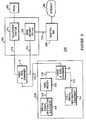
- FIG. 2is a diagram of an exemplary communication system 200 in accordance with the present invention, in which the system provides an analog voice signal on line 173 between a central office 250 and the building that contains the customer premise equipment 220 and provides an SDSL signal (using an SDSL service) on line 214 between the central office 250 and the building that contains the customer premise equipment 220 and in which the analog voice signal and the SDSL signal are combined at a first voice and SDSL combiner 11 located in or near the building that contains the CPE 220 therefore allowing the consumer to use only one twisted-pair line between their CPE 220 and the location of the combiner 11 .
- FIG. 3is a block diagram of an exemplary voice and SDSL combiner 10 in accordance with the present invention, in which the device combines and separates analog voice signals and SDSL signals as required in the systems depicted in FIGS. 2 and 4.
- FIG. 4is a diagram of a simplified communication system 30 that includes a system for combining a voice signal and an SDSL signal on a single combined line in accordance with the present invention.
- FIG. 2is a diagram of an improved system 200 for transmitting an analog voice signal between customer premise equipment (“CPE”) 220 and a central office 250 of a telephone service provider, and an SDSL signal between the CPE 220 and an SDSL service provider equipment 213 located in the central office 250 according to the present invention.
- the analog voice signal on line 173 and the SDSL signal on line 214are combined and separated by the first and second voice and SDSL combiners 11 and 12 , as described below.
- the system 200 shown in FIG. 2includes equipment known to those skilled in the art and which operate as already described in FIG. 1, as follows: the PSTN 190 , the central office 250 , the analog voice twisted pair of wires 173 , the call signal destination equipment 144 , the Internet 180 , the Router/ISP 260 , the SDSL twisted pair of wires 214 , the SDSL modem 212 , the digital signal destination equipment 148 , and line 145 coupling the modem 212 to the equipment 148 .
- the preferred embodiment 200also includes a first voice and SDSL combiner 11 , ideally situated at a location (which may be a common wiring closet) in or near the building that contains the CPE 220 , near the existing voice signal wires 173 and 210 , and near where the twisted pair of wires 214 supplied by the SDSL service provider terminate, such that additional wiring is minimized.
- the first voice and SDSL combiner 11is coupled to the telephone switch 174 of the CO 250 via the analog voice line 173 and to the SDSL Modem/DSLAM 213 of the CO 250 via analog data line 214 .
- the first voice and SDSL combiner 11combines the analog voice signal on line 173 with the SDSL signal on line 214 to generate a combined voice/SDSL signal on line 210 .
- a second voice and SDSL combiner 12receives the combined voice/SDSL signal on line 210 and separates the signal into an analog voice signal on line 143 and an SDSL signal on line 216 .
- the second voice and SDSL combiner 12also combines the analog voice signal on line 143 and the SDSL signal on line 216 into the combined voice/SDSL signal on line 210 .
- the analog voice signal on line 143is substantially the same as the analog voice signal received on line 173 .
- the SDSL signal on line 216is substantially the same as the SDSL signal received on line 214 , except for possible attenuation of a baseband segment (baseband or DC to a predetermined frequency) of the frequency spectrum of the SDSL signal.
- the SDSL modem 212processes the signal using essentially the full frequency spectrum, which results in acceptable or manageable signal errors.
- the combiner 11 in conjunction with combiner 12prevents or eliminates the corruption or further attenuation of the SDSL signal even when it is combined with a voice signal during voice signal transients, while not including or requiring complex DSP circuitry as in prior art systems including ADSL systems.
- the voice and SDSL combiners 11 and 12process signals traveling toward the CPE 220 , it should be understood that the combiners, being ideally identical, also process signals traveling away from the CPE 220 in essentially the same way.
- an additional pair of wiresmay need to be installed between some location (such as a common wiring closet as described above) and the customer prenise equipment (CPE).
- CPEcustomer prenise equipment
- FIG. 3presents an exemplary voice and SDSL combiner 10 suitable for use as the first and second voice and SDSL combiners 11 and 12 .
- the combiner 10includes a voice signal filtering section 20 , a SDSL signal filtering section 50 , a voice signal two-wire line or port 15 , a combined voice/SDSL signal two-wire line or port 14 , and a SDSL signal two-wire line or port 16 .
- combined analog voice/SDSL signals that are received at port 14are processed by the voice signal filtering section 20 and by the SDSL signal filtering section 50 .
- voice signals that are received at port 15 and SDSL signals that are received at port 16are processed by sections 20 and 50 respectively to provide a combined analog voice/SDSL signal at port 14 .
- the voice signal filtering section 20provides voice signals on line 15 by filtering or extracting voice signals from the combined voice/SDSL signals on line 14 .
- the voice signal filtering section 20also filters voice signals from line 15 to allow them to be combined with the SDSL signal, and includes circuitry that prevents voice signal transients from affecting or noticeably corrupting the SDSL signal.
- the SDSL signal filtering section 50provides SDSL signals on line 16 by filtering or extracting SDSL signals from the combined voice/SDSL signals on line 14 .
- the SDSL signal filtering section 50also filters SDSL signals from line 16 to allow them to be combined with the voice signal.
- the SDSL signal filtering section 50does not impact the voice signal or impact SDSL modems coupled to the voice and SDSL combiner 10 .
- the combiner 10should not cause detectable distortion to either signal and also not impact devices that are commonly connected to the combiner 10 as noted.
- an SDSL modemmay be connected to the port 16 for receiving SDSL signals generated by the combiner 10 from combined voice/SDSL signals received on line 14 .
- the possible signals on line 14should be considered, in particular transients in the voice signal.
- the voice signaloccupies a frequency band of zero to 3.4 KHz.
- transientsmay be generated in the analog voice signal. Such transients include ringing, generation of pulse tones, and taking a phone off-hook during ringing or non-ringing.
- the SDSL signalmay have a frequency spectrum that extends from baseband or DC to a predetermined upper limit frequency as a function of the encoding technique used in the SDSL modems and the data rate of the SDSL signal.
- a lower section or baseband section of the frequency spectrum of the SDSL signalis attenuated in order to enable the voice signal to be combined with the attenuated SDSL signal during steady state of the voice signal.
- This design criterion(the attenuation of a baseband section of the SDSL signal) is made known to the SDSL service provider and customer. As noted, the design criterion does not introduce significant errors in the SDSL modem or resultant digital data.
- the combiner 10ideally filters the combined voice/SDSL signal to extract the voice signal using a low pass filter having a cutoff frequency substantially higher than the upper voice frequency. This reduces possible distortion of the voice signal due to the filter. Further, the combiner 10 ideally filters the combined voice/SDSL signal to extract the SDSL signal using a high pass filter having a cutoff frequency greater than that of the low pass filter that is used for the voice signal. This selection of the cutoffs for the low pass filter and high pass filter helps prevent spectrum leakage from affecting the voice and SDSL signals during filtering.
- the possible analog voice signal transientsinclude 1) the introduction of a ring voltage in the voice signal; 2) the DC voltage/current of the voice signal; 3) the introduction of dial tones or pulses in the voice signal; 4) the change in DC voltage/current of the voice signal when a telephone device coupled to the voice line goes off-hook (shorting the line); and 5) the change in ring voltage present on the voice signal when a telephone device coupled to the voice line goes off-hook (shorting the line) during the presence of the ring voltage (during ringing).
- the combiner 10ideally should be able to prevent any of these signals from disturbing or influencing the SDSL signal in such a manner as to disrupt the SDSL modem's demodulation process (act of receiving and correctly decoding the information within the SDSL signal) and thus prevent producing errors in the resultant digital data stream.
- the combiner 10should be able to provide undistorted SDSL signals on line 16 even when voice signal transients are present.
- the circuitry of the combiner 10 and the mechanics thereof that suppresses the effects of voice signal transients on the SDSL signalare presented below.
- the high pass filter for the SDSL signalsshould not add significant or greatly variable group delay to the SDSL signal.
- an SDSL modemis coupled to line 16 of combiner 10 .
- These modemsinclude equalization circuitry that attempts to equalize delays caused by the transmission of the SDSL signal from one SDSL modem to another.
- the introduction of group delay by the high pass filtermay place an additional burden on the equalization circuitry of these modems.
- the group delaymay introduce data errors when the equalization circuitry is not able to fully compensate for the group delay introduced by the filter. Accordingly, the high pass filter should be designed so the filter does not introduce unequalizable group delays.
- the impedance of one filtermay be projected onto the other filter.
- prior art combinerssuch as ADSL splitters
- the impedance to high frequency signals, as presented by the low pass filtermay distort the higher frequency signals of the SDSL signal.
- the voice signal filter section 20uses a low pass filter that overcomes the limitations of the prior art
- the SDSL signal filter section 50uses a high pass filter that overcomes the limitations of the prior art.
- the cutoff of its low pass filter (“LPF”)should be much higher than the upper frequency spectrum of the voice signal during steady state.
- the cutoffis at least twice as great as the 3.4 KHz upper range of the standard telephony voice signal, i.e.; it is greater than 6.8 KHz, and ideally in the range of 7.5 KHz to 8.0 KHz.
- the selection of this cutoff for the LPF of the voice signal filtering section 20reduces the impact of the filtering section 20 on voice signals. As shown in FIG.
- the voice signal filtering section 20includes a plurality of capacitors 22 , 24 , 26 , 34 , and 42 , two transformers acting as inductors 28 and 32 , and a plurality of diodes 36 , 38 , 44 , and 46 .
- the LPFhas a frequency response as shown in TABLE 1, which lists the attenuation of the filter in dB as a function of frequency. Viewing TABLE 1, it can be seen that the cutoff of the LPF of the voice filtering section 20 is about 7.5 KHz, as desired.
- Transient signals generated by telephony voice signalsmay introduce significant handling problems.
- compensating for a telephone device going off-hook (producing a short on port 15 ) while a ring voltage is present on line 14is particularly important.
- the telephone switch 22 of FIG. 4may produce a ringing signal while the analog voice device 26 goes off-hook. This produces a transient in the voice signal that exists between the telephone switch 22 and the analog voice device 26 of FIG. 4 .
- the two combiners 11 and 12should be able to suppress the transients so that an SDSL signal between the SDSL modems 1 and 24 of FIG. 4 is not affected.
- the transformers 28 and 32 (acting as inductors) of each combiner 11 and 12may produce a large spike of voltage up to 300 volts due to the presence of the ringing signal.
- the filters present in the combiners 11 and 12are designed to process steady state signals, so such a voltage spike would not be significantly attenuated by the filters and thus would corrupt the SDSL signal between the SDSL modems 1 and 24 . Such an interruption may disrupt the operation of the SDSL modems whereby the modems lose synchronization and where the lost of synchronization between the modem may lead to substantial data loss.
- the preferred embodiment 10includes the plurality of diodes 36 , 38 , 44 , and 46 .
- Diodes 36 and 38are placed in parallel with one winding of the transformer 28 and diodes 44 and 46 are placed in parallel with the other winding of the transformer 28 .
- the diodes 36 , 38 , 44 , and 46prevent the transformer 28 from generating a spike of voltage that may feed back to lines 14 and 16 .
- these diodeshelp prevent possible corruption or interruption of SDSL signals present on lines 14 and 16 due to this transient in the voice signal.
- the transformer 32is less likely to introduce or produce a voltage spike when such a transient occurs because capacitors 24 and 26 buffer such a transient before it reaches the transformer 32 .
- the SDSL signal filtering section 50includes a high pass filter (“HPF”).
- HPFreduces voice signals received from line 14 so that primarily only SDSL signals from line 14 are transmitted to line 16 .
- Filtersintroduce group delay to signals as they pass through. The presence of a complex filter may add variable group delay that is not easily equalized, increasing the complexity or burden of associated modems.
- the HPF of the preferred SDSL signal filtering section 50has a relatively short group delay and, in addition, the difference between the minimum group delay introduced by the HPF and the maximum group delay introduced by the HPF is small. This reduces the complexity of associated modems because the delay introduced by the combiner 10 is relatively constant and small.
- the data filtering section 50includes two capacitors 52 and 54 and an inductor 56 .
- the two capacitors 52 and 54 and the inductor 56are configured as shown in FIG. 4 to form an HPF that filters or reduces the presence of signals having a frequency spectrum lower than the cutoff of the filter.
- the HPF filter of the data filtering section 50has a frequency response as shown in TABLE 1, which lists the attenuation of the filter in dB as a function of frequency. Viewing TABLE 1, it can be seen that the cutoff of the HPF of the data filtering section 50 is about 24 KHz.
- this cutoff frequencymay affect SDSL signals on line 14 in some embodiments, in particular for a portion of the baseband spectrum below the cutoff of this filter and of the low pass filter as described above. This cutoff is selected, however, to reduce interference between the voice signal filtering section 20 and the SDSL signal filtering section 50 .
- the cutoffs of the LPF and HPF of sections 20 and 50are ideally separated to reduce interference between the filters.
- each filteralso generates signal impedance at the input of the other filter.
- the LPF of section 20generates signal impedance at the input of the HPF of section 50 .
- An LPFcommonly terminates with a capacitor that may present low shunt impedance at the input of a parallel HPF.
- FIG. 1shows that the LPF and HPF of sections 20 and 50 .
- the LPF of the voice signal filtering section 20terminates with an inductor (transformer 32 acting as an inductor).
- the transformer 32has greater impedance as the frequencies increase and thus is less likely to short SDSL signals on line 14 .
- the combiner 10may be used to separate combined analog voice and SDSL signals while not causing significant distortion of either signal, even when transients occur in the voice signal.
Landscapes
- Engineering & Computer Science (AREA)
- Computer Networks & Wireless Communication (AREA)
- Signal Processing (AREA)
- Telephonic Communication Services (AREA)
- Cable Transmission Systems, Equalization Of Radio And Reduction Of Echo (AREA)
Abstract
Description
| TABLE 1 | ||
| LOW PASS FILTER RESPONSE | HIGH PASS FILTER RESPONSE | |
| Hz | dB | kHz | dB |
| 300 | −0.019 | 2 | 87.496 |
| 500 | −0.014 | 4 | 63.556 |
| 700 | −0.005 | 6 | 49.694 |
| 900 | 0.006 | 8 | 39.991 |
| 1100 | 0.020 | 10 | 32.581 |
| 1300 | 0.038 | 12 | 26.628 |
| 1500 | 0.058 | 14 | 21.684 |
| 1700 | 0.082 | 16 | 17.490 |
| 1900 | 0.108 | 18 | 13.894 |
| 2100 | 0.138 | 20 | 10.811 |
| 2300 | 0.170 | 22 | 8.203 |
| 2500 | 0.205 | 24 | 6.055 |
| 2700 | 0.242 | 26 | 4.351 |
| 2900 | 0.280 | 28 | 3.059 |
| 3100 | 0.321 | 30 | 2.119 |
| 3300 | 0.362 | 32 | 1.458 |
| 3500 | 0.403 | 34 | 1.003 |
| 3700 | 0.474 | 36 | 0.694 |
| 3900 | 0.484 | 38 | 0.484 |
| 4100 | 0.523 | 40 | 0.341 |
| 4300 | 0.559 | 42 | 0.243 |
| 4500 | 0.593 | 44 | 0.175 |
| 4700 | 0.625 | 46 | 0.128 |
| 4900 | 0.656 | 48 | 0.094 |
| 5100 | 0.688 | 50 | 0.070 |
| 5300 | 0.724 | 52 | 0.052 |
| 5500 | 0.772 | 54 | 0.040 |
| 5700 | 0.839 | 56 | 0.030 |
| 5900 | 0.940 | 58 | 0.023 |
| 6100 | 1.094 | 60 | 0.018 |
| 6300 | 1.327 | 62 | 0.013 |
| 6500 | 1.669 | 64 | 0.010 |
| 6700 | 2.153 | 66 | 0.008 |
| 6900 | 2.805 | 68 | 0.006 |
| 7100 | 3.644 | 70 | 0.004 |
| 7300 | 4.672 | 72 | 0.003 |
| 7500 | 5.877 | 74 | 0.002 |
| 7700 | 7.237 | 76 | 0.001 |
| 7900 | 8.729 | 78 | 0.001 |
| 8100 | 10.334 | 80 | 0.000 |
| 8300 | 12.041 | 82 | −0.001 |
| 8500 | 13.847 | 84 | −0.001 |
| 8700 | 15.762 | 86 | −0.001 |
| 8900 | 17.806 | 88 | −0.002 |
| 9100 | 20.021 | 90 | −0.002 |
| 9300 | 22.473 | 92 | −0.603 |
| 9500 | 25.277 | 94 | −0.003 |
| 9700 | 28.661 | 96 | −0.003 |
| 9900 | 33.151 | 98 | −0.003 |
| 10100 | 40.555 | 100 | −0.004 |
Claims (25)
Priority Applications (5)
| Application Number | Priority Date | Filing Date | Title |
|---|---|---|---|
| US09/425,472US6693916B1 (en) | 1999-10-22 | 1999-10-22 | Method and system for combining symmetric DSL signals and voice signals |
| AU77279/00AAU7727900A (en) | 1999-10-22 | 2000-09-28 | Method and system for combining symmetric dsl signals and voice signals |
| PCT/US2000/026660WO2001031904A2 (en) | 1999-10-22 | 2000-09-28 | Method and system for combining symmetric dsl signals and voice signals |
| TW089121959ATW493331B (en) | 1999-10-22 | 2000-10-19 | Method and system for combining symmetric DSL signals and voice signals |
| US10/753,699US7391764B2 (en) | 1999-10-22 | 2004-01-07 | Method and system for combining symmetric DSL signals and voice signals |
Applications Claiming Priority (1)
| Application Number | Priority Date | Filing Date | Title |
|---|---|---|---|
| US09/425,472US6693916B1 (en) | 1999-10-22 | 1999-10-22 | Method and system for combining symmetric DSL signals and voice signals |
Related Child Applications (1)
| Application Number | Title | Priority Date | Filing Date |
|---|---|---|---|
| US10/753,699ContinuationUS7391764B2 (en) | 1999-10-22 | 2004-01-07 | Method and system for combining symmetric DSL signals and voice signals |
Publications (1)
| Publication Number | Publication Date |
|---|---|
| US6693916B1true US6693916B1 (en) | 2004-02-17 |
Family
ID=23686712
Family Applications (2)
| Application Number | Title | Priority Date | Filing Date |
|---|---|---|---|
| US09/425,472Expired - LifetimeUS6693916B1 (en) | 1999-10-22 | 1999-10-22 | Method and system for combining symmetric DSL signals and voice signals |
| US10/753,699Expired - LifetimeUS7391764B2 (en) | 1999-10-22 | 2004-01-07 | Method and system for combining symmetric DSL signals and voice signals |
Family Applications After (1)
| Application Number | Title | Priority Date | Filing Date |
|---|---|---|---|
| US10/753,699Expired - LifetimeUS7391764B2 (en) | 1999-10-22 | 2004-01-07 | Method and system for combining symmetric DSL signals and voice signals |
Country Status (4)
| Country | Link |
|---|---|
| US (2) | US6693916B1 (en) |
| AU (1) | AU7727900A (en) |
| TW (1) | TW493331B (en) |
| WO (1) | WO2001031904A2 (en) |
Cited By (30)
| Publication number | Priority date | Publication date | Assignee | Title |
|---|---|---|---|---|
| US20010016000A1 (en)* | 2000-01-06 | 2001-08-23 | Alain Benayoun | Method and system for dynamically inverting an asymmetric digital subscriber line (ADSL) System |
| US20020003802A1 (en)* | 2000-07-06 | 2002-01-10 | Il-Kyong Kim | Method for providing high-speed data service and voice service |
| US20020101882A1 (en)* | 2000-08-05 | 2002-08-01 | Man-Duck Kim | Transmission of voice and information signals in a single line |
| US20030026418A1 (en)* | 1999-05-11 | 2003-02-06 | Hong Cui | Dynamically adjustable digital gyrator having extendable feedback for stable DC load line |
| US20040101115A1 (en)* | 2002-09-03 | 2004-05-27 | Siemens Aktiengesellschaft | System for voice and data communication via a common subscriber line |
| US20040125819A1 (en)* | 2001-07-05 | 2004-07-01 | Yehuda Binder | Telephone outlet with packet telephony adapter, and a network using same |
| US20050008033A1 (en)* | 2000-04-18 | 2005-01-13 | Serconet Ltd. | Telephone communication system over a single telephone line |
| US20050010954A1 (en)* | 2003-07-09 | 2005-01-13 | Serconet Ltd. | Modular outlet |
| US20050047431A1 (en)* | 2001-10-11 | 2005-03-03 | Serconet Ltd. | Outlet with analog signal adapter, a method for use thereof and a network using said outlet |
| US6898280B1 (en)* | 2000-11-15 | 2005-05-24 | Lucent Technologies Inc. | Line card and method for supporting pots, asymmetric DSL and symmetric DSL services |
| US20050249245A1 (en)* | 2004-05-06 | 2005-11-10 | Serconet Ltd. | System and method for carrying a wireless based signal over wiring |
| US20050277328A1 (en)* | 2000-04-19 | 2005-12-15 | Serconet Ltd | Network combining wired and non-wired segments |
| US20060072741A1 (en)* | 2003-01-30 | 2006-04-06 | Serconet Ltd | Method and system for providing DC power on local telephone lines |
| US7031378B1 (en)* | 2000-06-23 | 2006-04-18 | Globespan, Inc. | Unified DSL transceiver |
| US20060133588A1 (en)* | 2000-03-20 | 2006-06-22 | Serconet Ltd. | Telephone outlet for implementing a local area network over telephone lines and a local area network using such outlets |
| US20070086444A1 (en)* | 2003-03-13 | 2007-04-19 | Serconet Ltd. | Telephone system having multiple distinct sources and accessories therefor |
| US20070173202A1 (en)* | 2006-01-11 | 2007-07-26 | Serconet Ltd. | Apparatus and method for frequency shifting of a wireless signal and systems using frequency shifting |
| US20070253443A1 (en)* | 2006-04-27 | 2007-11-01 | Sbc Knowledge Ventures L.P. | Data services over G.SHDSL transport infrastructure |
| US7352711B1 (en)* | 1999-10-29 | 2008-04-01 | Infineon Technologies Ag | Circuit arrangement and method for data transmission |
| US20080175361A1 (en)* | 2007-01-19 | 2008-07-24 | Vonage Network | Apparatus and method for coextensive operation of multiple broadband services on a local network |
| US20080292073A1 (en)* | 1999-07-20 | 2008-11-27 | Serconet, Ltd | Network for telephony and data communication |
| US7873058B2 (en) | 2004-11-08 | 2011-01-18 | Mosaid Technologies Incorporated | Outlet with analog signal adapter, a method for use thereof and a network using said outlet |
| US20110058661A1 (en)* | 2008-04-30 | 2011-03-10 | Huawei Device Co., Ltd. | Method, apparatus, and system for processing a voice service |
| US8175649B2 (en) | 2008-06-20 | 2012-05-08 | Corning Mobileaccess Ltd | Method and system for real time control of an active antenna over a distributed antenna system |
| US8270430B2 (en) | 1998-07-28 | 2012-09-18 | Mosaid Technologies Incorporated | Local area network of serial intelligent cells |
| US8594133B2 (en) | 2007-10-22 | 2013-11-26 | Corning Mobileaccess Ltd. | Communication system using low bandwidth wires |
| US8897215B2 (en) | 2009-02-08 | 2014-11-25 | Corning Optical Communications Wireless Ltd | Communication system using cables carrying ethernet signals |
| US9184960B1 (en) | 2014-09-25 | 2015-11-10 | Corning Optical Communications Wireless Ltd | Frequency shifting a communications signal(s) in a multi-frequency distributed antenna system (DAS) to avoid or reduce frequency interference |
| US9338823B2 (en) | 2012-03-23 | 2016-05-10 | Corning Optical Communications Wireless Ltd | Radio-frequency integrated circuit (RFIC) chip(s) for providing distributed antenna system functionalities, and related components, systems, and methods |
| US10986165B2 (en) | 2004-01-13 | 2021-04-20 | May Patents Ltd. | Information device |
Families Citing this family (3)
| Publication number | Priority date | Publication date | Assignee | Title |
|---|---|---|---|---|
| US7672294B2 (en)* | 2004-09-30 | 2010-03-02 | Alcatel-Lucent Usa Inc. | Methods and devices for achieving parallel operation between IP and analog phones |
| US8676254B2 (en)* | 2005-10-12 | 2014-03-18 | Mark D. Hedstrom | Cellular phone line replacement adapter |
| CA2960491A1 (en)* | 2017-03-10 | 2018-09-10 | Comtest Networks Inc. | Signal splitter/combiner with an electro-magnetic interference filter |
Citations (5)
| Publication number | Priority date | Publication date | Assignee | Title |
|---|---|---|---|---|
| US5757803A (en) | 1995-11-27 | 1998-05-26 | Analog Devices, Inc. | Pots splitter assembly with improved transhybrid loss for digital subscriber loop transmission |
| EP0917392A2 (en) | 1997-11-12 | 1999-05-19 | Nortel Networks Corporation | Communication system architecture, exchange and method of operation |
| EP0923221A1 (en) | 1997-12-09 | 1999-06-16 | Nortel Networks Corporation | Communications signal splitter and filter |
| US6069899A (en)* | 1997-08-28 | 2000-05-30 | Broadcam Homenetworking, Inc. | Home area network system and method |
| US6424661B1 (en)* | 1998-06-25 | 2002-07-23 | Alcatel Usa Sourcing, L.P. | ADSL with RF POTS overlay |
Family Cites Families (3)
| Publication number | Priority date | Publication date | Assignee | Title |
|---|---|---|---|---|
| US6061392A (en)* | 1996-12-17 | 2000-05-09 | Paradyne Corporation | Apparatus and method for communicating voice and data between a customer premises and a central office |
| US6760383B1 (en)* | 1999-03-09 | 2004-07-06 | Nortel Networks Limited | Long reach SDSL system spectrally compatible with ADSL systems |
| US6674843B1 (en)* | 1999-05-28 | 2004-01-06 | Cisco Technology, Inc. | Apparatus system and method for enabling multi-frequency communication over a telephone network having a billing/tax tone |
- 1999
- 1999-10-22USUS09/425,472patent/US6693916B1/ennot_activeExpired - Lifetime
- 2000
- 2000-09-28WOPCT/US2000/026660patent/WO2001031904A2/enactiveApplication Filing
- 2000-09-28AUAU77279/00Apatent/AU7727900A/ennot_activeAbandoned
- 2000-10-19TWTW089121959Apatent/TW493331B/ennot_activeIP Right Cessation
- 2004
- 2004-01-07USUS10/753,699patent/US7391764B2/ennot_activeExpired - Lifetime
Patent Citations (5)
| Publication number | Priority date | Publication date | Assignee | Title |
|---|---|---|---|---|
| US5757803A (en) | 1995-11-27 | 1998-05-26 | Analog Devices, Inc. | Pots splitter assembly with improved transhybrid loss for digital subscriber loop transmission |
| US6069899A (en)* | 1997-08-28 | 2000-05-30 | Broadcam Homenetworking, Inc. | Home area network system and method |
| EP0917392A2 (en) | 1997-11-12 | 1999-05-19 | Nortel Networks Corporation | Communication system architecture, exchange and method of operation |
| EP0923221A1 (en) | 1997-12-09 | 1999-06-16 | Nortel Networks Corporation | Communications signal splitter and filter |
| US6424661B1 (en)* | 1998-06-25 | 2002-07-23 | Alcatel Usa Sourcing, L.P. | ADSL with RF POTS overlay |
Cited By (108)
| Publication number | Priority date | Publication date | Assignee | Title |
|---|---|---|---|---|
| US8867523B2 (en) | 1998-07-28 | 2014-10-21 | Conversant Intellectual Property Management Incorporated | Local area network of serial intelligent cells |
| US8908673B2 (en) | 1998-07-28 | 2014-12-09 | Conversant Intellectual Property Management Incorporated | Local area network of serial intelligent cells |
| US8885659B2 (en) | 1998-07-28 | 2014-11-11 | Conversant Intellectual Property Management Incorporated | Local area network of serial intelligent cells |
| US8270430B2 (en) | 1998-07-28 | 2012-09-18 | Mosaid Technologies Incorporated | Local area network of serial intelligent cells |
| US8325636B2 (en) | 1998-07-28 | 2012-12-04 | Mosaid Technologies Incorporated | Local area network of serial intelligent cells |
| US8885660B2 (en) | 1998-07-28 | 2014-11-11 | Conversant Intellectual Property Management Incorporated | Local area network of serial intelligent cells |
| US20030026418A1 (en)* | 1999-05-11 | 2003-02-06 | Hong Cui | Dynamically adjustable digital gyrator having extendable feedback for stable DC load line |
| US6888938B2 (en)* | 1999-05-11 | 2005-05-03 | Agere Systems Inc. | Dynamically adjustable digital gyrator having extendable feedback for stable DC load line |
| US20080292073A1 (en)* | 1999-07-20 | 2008-11-27 | Serconet, Ltd | Network for telephony and data communication |
| US7522713B2 (en) | 1999-07-20 | 2009-04-21 | Serconet, Ltd. | Network for telephony and data communication |
| US8351582B2 (en) | 1999-07-20 | 2013-01-08 | Mosaid Technologies Incorporated | Network for telephony and data communication |
| US7483524B2 (en) | 1999-07-20 | 2009-01-27 | Serconet, Ltd | Network for telephony and data communication |
| US8929523B2 (en) | 1999-07-20 | 2015-01-06 | Conversant Intellectual Property Management Inc. | Network for telephony and data communication |
| US7492875B2 (en) | 1999-07-20 | 2009-02-17 | Serconet, Ltd. | Network for telephony and data communication |
| US7352711B1 (en)* | 1999-10-29 | 2008-04-01 | Infineon Technologies Ag | Circuit arrangement and method for data transmission |
| US20080151924A1 (en)* | 1999-10-29 | 2008-06-26 | Infineon Technologies Ag | Circuit arrangement and method for data transmission |
| US8031748B2 (en) | 1999-10-29 | 2011-10-04 | Lantiq Deutschland Gmbh | Circuit arrangement and method for data transmission |
| US20010016000A1 (en)* | 2000-01-06 | 2001-08-23 | Alain Benayoun | Method and system for dynamically inverting an asymmetric digital subscriber line (ADSL) System |
| US6888884B2 (en)* | 2000-01-06 | 2005-05-03 | International Business Machines Corporation | Method and system for dynamically inverting an asymmetric digital subscriber line (ADSL) system |
| US8363797B2 (en) | 2000-03-20 | 2013-01-29 | Mosaid Technologies Incorporated | Telephone outlet for implementing a local area network over telephone lines and a local area network using such outlets |
| US7715534B2 (en) | 2000-03-20 | 2010-05-11 | Mosaid Technologies Incorporated | Telephone outlet for implementing a local area network over telephone lines and a local area network using such outlets |
| US20060133588A1 (en)* | 2000-03-20 | 2006-06-22 | Serconet Ltd. | Telephone outlet for implementing a local area network over telephone lines and a local area network using such outlets |
| US8855277B2 (en) | 2000-03-20 | 2014-10-07 | Conversant Intellectual Property Managment Incorporated | Telephone outlet for implementing a local area network over telephone lines and a local area network using such outlets |
| US7522714B2 (en) | 2000-03-20 | 2009-04-21 | Serconet Ltd. | Telephone outlet for implementing a local area network over telephone lines and a local area network using such outlets |
| US20050117603A1 (en)* | 2000-04-18 | 2005-06-02 | Serconet, Ltd. | Telephone communication system over a single telephone line |
| US7593394B2 (en) | 2000-04-18 | 2009-09-22 | Mosaid Technologies Incorporated | Telephone communication system over a single telephone line |
| US8559422B2 (en) | 2000-04-18 | 2013-10-15 | Mosaid Technologies Incorporated | Telephone communication system over a single telephone line |
| US7466722B2 (en) | 2000-04-18 | 2008-12-16 | Serconet Ltd | Telephone communication system over a single telephone line |
| US7274688B2 (en) | 2000-04-18 | 2007-09-25 | Serconet Ltd. | Telephone communication system over a single telephone line |
| US8223800B2 (en) | 2000-04-18 | 2012-07-17 | Mosaid Technologies Incorporated | Telephone communication system over a single telephone line |
| US7397791B2 (en) | 2000-04-18 | 2008-07-08 | Serconet, Ltd. | Telephone communication system over a single telephone line |
| US20050008033A1 (en)* | 2000-04-18 | 2005-01-13 | Serconet Ltd. | Telephone communication system over a single telephone line |
| US20060182095A1 (en)* | 2000-04-18 | 2006-08-17 | Serconet Ltd. | Telephone communication system over a single telephone line |
| US8000349B2 (en) | 2000-04-18 | 2011-08-16 | Mosaid Technologies Incorporated | Telephone communication system over a single telephone line |
| US20050277328A1 (en)* | 2000-04-19 | 2005-12-15 | Serconet Ltd | Network combining wired and non-wired segments |
| US8873586B2 (en) | 2000-04-19 | 2014-10-28 | Conversant Intellectual Property Management Incorporated | Network combining wired and non-wired segments |
| US7633966B2 (en) | 2000-04-19 | 2009-12-15 | Mosaid Technologies Incorporated | Network combining wired and non-wired segments |
| US8848725B2 (en) | 2000-04-19 | 2014-09-30 | Conversant Intellectual Property Management Incorporated | Network combining wired and non-wired segments |
| US8982904B2 (en) | 2000-04-19 | 2015-03-17 | Conversant Intellectual Property Management Inc. | Network combining wired and non-wired segments |
| US8867506B2 (en) | 2000-04-19 | 2014-10-21 | Conversant Intellectual Property Management Incorporated | Network combining wired and non-wired segments |
| US8873575B2 (en) | 2000-04-19 | 2014-10-28 | Conversant Intellectual Property Management Incorporated | Network combining wired and non-wired segments |
| US7031378B1 (en)* | 2000-06-23 | 2006-04-18 | Globespan, Inc. | Unified DSL transceiver |
| US6970502B2 (en)* | 2000-07-06 | 2005-11-29 | Samsung Electronics Co., Ltd. | Method for providing high-speed data service and voice service |
| US20020003802A1 (en)* | 2000-07-06 | 2002-01-10 | Il-Kyong Kim | Method for providing high-speed data service and voice service |
| US20020101882A1 (en)* | 2000-08-05 | 2002-08-01 | Man-Duck Kim | Transmission of voice and information signals in a single line |
| US6898280B1 (en)* | 2000-11-15 | 2005-05-24 | Lucent Technologies Inc. | Line card and method for supporting pots, asymmetric DSL and symmetric DSL services |
| US20040125819A1 (en)* | 2001-07-05 | 2004-07-01 | Yehuda Binder | Telephone outlet with packet telephony adapter, and a network using same |
| US8472593B2 (en) | 2001-07-05 | 2013-06-25 | Mosaid Technologies Incorporated | Telephone outlet with packet telephony adaptor, and a network using same |
| US7542554B2 (en) | 2001-07-05 | 2009-06-02 | Serconet, Ltd | Telephone outlet with packet telephony adapter, and a network using same |
| US7680255B2 (en) | 2001-07-05 | 2010-03-16 | Mosaid Technologies Incorporated | Telephone outlet with packet telephony adaptor, and a network using same |
| US8761186B2 (en) | 2001-07-05 | 2014-06-24 | Conversant Intellectual Property Management Incorporated | Telephone outlet with packet telephony adapter, and a network using same |
| US20050083959A1 (en)* | 2001-07-05 | 2005-04-21 | Serconet, Ltd. | Telephone outlet with packet telephony adapter, and a network using same |
| US20050063403A1 (en)* | 2001-07-05 | 2005-03-24 | Serconet Ltd. | Telephone outlet with packet telephony adaptor, and a network using same |
| US7769030B2 (en) | 2001-07-05 | 2010-08-03 | Mosaid Technologies Incorporated | Telephone outlet with packet telephony adapter, and a network using same |
| US20060098638A1 (en)* | 2001-10-11 | 2006-05-11 | Serconet Ltd. | Outlet with analog signal adapter, a method for use thereof and a network using said outlet |
| US7860084B2 (en) | 2001-10-11 | 2010-12-28 | Mosaid Technologies Incorporated | Outlet with analog signal adapter, a method for use thereof and a network using said outlet |
| US20050047431A1 (en)* | 2001-10-11 | 2005-03-03 | Serconet Ltd. | Outlet with analog signal adapter, a method for use thereof and a network using said outlet |
| US20080134263A1 (en)* | 2001-10-11 | 2008-06-05 | Serconet Ltd. | Outlet with analog signal adapter, a method for use thereof and a network using said outlet |
| US7889720B2 (en) | 2001-10-11 | 2011-02-15 | Mosaid Technologies Incorporated | Outlet with analog signal adapter, a method for use thereof and a network using said outlet |
| US7453895B2 (en) | 2001-10-11 | 2008-11-18 | Serconet Ltd | Outlet with analog signal adapter, a method for use thereof and a network using said outlet |
| US20110096778A1 (en)* | 2001-10-11 | 2011-04-28 | Mosaid Technologies Incorporated | Outlet with analog signal adapter, a method for use thereof and a network using said outlet |
| US7953071B2 (en) | 2001-10-11 | 2011-05-31 | Mosaid Technologies Incorporated | Outlet with analog signal adapter, a method for use thereof and a network using said outlet |
| US7436842B2 (en) | 2001-10-11 | 2008-10-14 | Serconet Ltd. | Outlet with analog signal adapter, a method for use thereof and a network using said outlet |
| US20040101115A1 (en)* | 2002-09-03 | 2004-05-27 | Siemens Aktiengesellschaft | System for voice and data communication via a common subscriber line |
| US7406099B2 (en)* | 2002-09-03 | 2008-07-29 | Siemens Aktiengesellschaft | System for voice and data communication via a common subscriber line |
| US20070127715A1 (en)* | 2003-01-30 | 2007-06-07 | Serconet Ltd | Method and system for providing DC power on local telephone lines |
| US8107618B2 (en) | 2003-01-30 | 2012-01-31 | Mosaid Technologies Incorporated | Method and system for providing DC power on local telephone lines |
| US20060072741A1 (en)* | 2003-01-30 | 2006-04-06 | Serconet Ltd | Method and system for providing DC power on local telephone lines |
| US20060233354A1 (en)* | 2003-01-30 | 2006-10-19 | Serconet Ltd | Method and system for providing DC power on local telephone Lines |
| US7317793B2 (en) | 2003-01-30 | 2008-01-08 | Serconet Ltd | Method and system for providing DC power on local telephone lines |
| US8787562B2 (en) | 2003-01-30 | 2014-07-22 | Conversant Intellectual Property Management Inc. | Method and system for providing DC power on local telephone lines |
| US7702095B2 (en) | 2003-01-30 | 2010-04-20 | Mosaid Technologies Incorporated | Method and system for providing DC power on local telephone lines |
| US20070086444A1 (en)* | 2003-03-13 | 2007-04-19 | Serconet Ltd. | Telephone system having multiple distinct sources and accessories therefor |
| US8238328B2 (en) | 2003-03-13 | 2012-08-07 | Mosaid Technologies Incorporated | Telephone system having multiple distinct sources and accessories therefor |
| US20050010954A1 (en)* | 2003-07-09 | 2005-01-13 | Serconet Ltd. | Modular outlet |
| US7867035B2 (en) | 2003-07-09 | 2011-01-11 | Mosaid Technologies Incorporated | Modular outlet |
| US8360810B2 (en) | 2003-09-07 | 2013-01-29 | Mosaid Technologies Incorporated | Modular outlet |
| US8092258B2 (en) | 2003-09-07 | 2012-01-10 | Mosaid Technologies Incorporated | Modular outlet |
| US20070041340A1 (en)* | 2003-09-07 | 2007-02-22 | Serconet Ltd. | Modular outlet |
| US8235755B2 (en) | 2003-09-07 | 2012-08-07 | Mosaid Technologies Incorporated | Modular outlet |
| US20110097939A1 (en)* | 2003-09-07 | 2011-04-28 | Mosaid Technologies Incorporated | Modular outlet |
| US8591264B2 (en) | 2003-09-07 | 2013-11-26 | Mosaid Technologies Incorporated | Modular outlet |
| US7686653B2 (en) | 2003-09-07 | 2010-03-30 | Mosaid Technologies Incorporated | Modular outlet |
| US11095708B2 (en) | 2004-01-13 | 2021-08-17 | May Patents Ltd. | Information device |
| US10986165B2 (en) | 2004-01-13 | 2021-04-20 | May Patents Ltd. | Information device |
| US10986164B2 (en) | 2004-01-13 | 2021-04-20 | May Patents Ltd. | Information device |
| US11032353B2 (en) | 2004-01-13 | 2021-06-08 | May Patents Ltd. | Information device |
| US8325759B2 (en) | 2004-05-06 | 2012-12-04 | Corning Mobileaccess Ltd | System and method for carrying a wireless based signal over wiring |
| US20050249245A1 (en)* | 2004-05-06 | 2005-11-10 | Serconet Ltd. | System and method for carrying a wireless based signal over wiring |
| US7873058B2 (en) | 2004-11-08 | 2011-01-18 | Mosaid Technologies Incorporated | Outlet with analog signal adapter, a method for use thereof and a network using said outlet |
| US20070173202A1 (en)* | 2006-01-11 | 2007-07-26 | Serconet Ltd. | Apparatus and method for frequency shifting of a wireless signal and systems using frequency shifting |
| US7813451B2 (en) | 2006-01-11 | 2010-10-12 | Mobileaccess Networks Ltd. | Apparatus and method for frequency shifting of a wireless signal and systems using frequency shifting |
| US8184681B2 (en) | 2006-01-11 | 2012-05-22 | Corning Mobileaccess Ltd | Apparatus and method for frequency shifting of a wireless signal and systems using frequency shifting |
| US7587001B2 (en) | 2006-01-11 | 2009-09-08 | Serconet Ltd. | Apparatus and method for frequency shifting of a wireless signal and systems using frequency shifting |
| US20070253443A1 (en)* | 2006-04-27 | 2007-11-01 | Sbc Knowledge Ventures L.P. | Data services over G.SHDSL transport infrastructure |
| US20080175361A1 (en)* | 2007-01-19 | 2008-07-24 | Vonage Network | Apparatus and method for coextensive operation of multiple broadband services on a local network |
| US8594133B2 (en) | 2007-10-22 | 2013-11-26 | Corning Mobileaccess Ltd. | Communication system using low bandwidth wires |
| US9813229B2 (en) | 2007-10-22 | 2017-11-07 | Corning Optical Communications Wireless Ltd | Communication system using low bandwidth wires |
| US9549301B2 (en) | 2007-12-17 | 2017-01-17 | Corning Optical Communications Wireless Ltd | Method and system for real time control of an active antenna over a distributed antenna system |
| US20110058661A1 (en)* | 2008-04-30 | 2011-03-10 | Huawei Device Co., Ltd. | Method, apparatus, and system for processing a voice service |
| US8379635B2 (en)* | 2008-04-30 | 2013-02-19 | Huawei Device Co., Ltd. | Method, apparatus, and system for processing a voice service |
| US8175649B2 (en) | 2008-06-20 | 2012-05-08 | Corning Mobileaccess Ltd | Method and system for real time control of an active antenna over a distributed antenna system |
| US8897215B2 (en) | 2009-02-08 | 2014-11-25 | Corning Optical Communications Wireless Ltd | Communication system using cables carrying ethernet signals |
| US9338823B2 (en) | 2012-03-23 | 2016-05-10 | Corning Optical Communications Wireless Ltd | Radio-frequency integrated circuit (RFIC) chip(s) for providing distributed antenna system functionalities, and related components, systems, and methods |
| US9948329B2 (en) | 2012-03-23 | 2018-04-17 | Corning Optical Communications Wireless, LTD | Radio-frequency integrated circuit (RFIC) chip(s) for providing distributed antenna system functionalities, and related components, systems, and methods |
| US9515855B2 (en) | 2014-09-25 | 2016-12-06 | Corning Optical Communications Wireless Ltd | Frequency shifting a communications signal(s) in a multi-frequency distributed antenna system (DAS) to avoid or reduce frequency interference |
| US9253003B1 (en) | 2014-09-25 | 2016-02-02 | Corning Optical Communications Wireless Ltd | Frequency shifting a communications signal(S) in a multi-frequency distributed antenna system (DAS) to avoid or reduce frequency interference |
| US9184960B1 (en) | 2014-09-25 | 2015-11-10 | Corning Optical Communications Wireless Ltd | Frequency shifting a communications signal(s) in a multi-frequency distributed antenna system (DAS) to avoid or reduce frequency interference |
Also Published As
| Publication number | Publication date |
|---|---|
| US7391764B2 (en) | 2008-06-24 |
| WO2001031904A2 (en) | 2001-05-03 |
| TW493331B (en) | 2002-07-01 |
| AU7727900A (en) | 2001-05-08 |
| WO2001031904A3 (en) | 2001-10-25 |
| US20040146068A1 (en) | 2004-07-29 |
Similar Documents
| Publication | Publication Date | Title |
|---|---|---|
| US6693916B1 (en) | Method and system for combining symmetric DSL signals and voice signals | |
| US6522730B1 (en) | DSL communication system with improved bandwidth | |
| CA2301546C (en) | Apparatus and method for concurrent voice and data transmission | |
| US20020101852A1 (en) | POTS/xDSL services line sharing for multiple subscribers | |
| WO2002078269A1 (en) | System and method for extending the range of xdsl services | |
| US6456650B1 (en) | Splitterless modem using harmonics reduction | |
| US7039180B1 (en) | Method and apparatus for enabling multiple protocol communication over a network | |
| US7305006B1 (en) | System for allowing a single device to share multiple transmission lines | |
| US6647024B1 (en) | System and method for an all digital communication system with a life line | |
| US6879601B2 (en) | Method and system for conveying multiple calls on a single telephone line | |
| EP1175077B1 (en) | A DSL-compatible line card for analog telephone lines | |
| US7400719B2 (en) | Subscriber line interface circuitry transceiver | |
| US7362856B2 (en) | Subscriber line interface circuitry transceiver | |
| US7218729B2 (en) | Subscriber line interface circuitry with current drivers for downstream voice and data signals | |
| US7362855B2 (en) | Subscriber line interface circuitry transceiver | |
| US7362857B2 (en) | Subscriber line interface circuitry transceiver | |
| EP2033388A2 (en) | Apparatus, method and system for providing new communication services over existing wiring | |
| US6795548B2 (en) | Method and system for data communication | |
| EP0990341B1 (en) | Vdsl modem divided into a digital and an analog part | |
| CA2692156A1 (en) | Apparatus, method and system for providing new communication services over existing wiring | |
| EP1318653B1 (en) | Line interface for combining a voice band signal and an XDSL signal on a twisted-pair copper line | |
| US7397914B2 (en) | Multiple path hybrid for subscriber line services | |
| WO2000078013A1 (en) | Loop driver for pots, xdsl, or integrated pots/xdsl interface | |
| US8514917B1 (en) | Method and apparatus for DSL communication over a 4 wire system | |
| EP2131563B1 (en) | Line termination board with multi type xDSL line high pass filters |
Legal Events
| Date | Code | Title | Description |
|---|---|---|---|
| AS | Assignment | Owner name:RC NETWORKS, INC., CALIFORNIA Free format text:ASSIGNMENT OF ASSIGNORS INTEREST;ASSIGNORS:CHAPLIK, NAOM;KASMIR, SETON P.;REEL/FRAME:010665/0960 Effective date:19991207 | |
| AS | Assignment | Owner name:AMPERSAND SPECIALTY MATERIALS AND CHEMICALS III LI Free format text:SECURITY INTEREST;ASSIGNOR:RC NETWORKS;REEL/FRAME:012244/0901 Effective date:20010904 Owner name:EDGEWATER PRIVATE EQUITY FUND III, L.P.A., CALIFOR Free format text:SECURITY INTEREST;ASSIGNOR:RC NETWORKS;REEL/FRAME:012244/0911 Effective date:20010904 | |
| AS | Assignment | Owner name:VIADUX, INC., CALIFORNIA Free format text:CHANGE OF NAME;ASSIGNOR:RC NETWORKS;REEL/FRAME:013297/0156 Effective date:20020528 | |
| AS | Assignment | Owner name:RC NETWORKS, CALIFORNIA Free format text:REASSIGNMENT AND RELEASE OF SECURITY INTEREST;ASSIGNOR:AMPERSAN 1995 LIMITED PARTNERSHIP;REEL/FRAME:013380/0027 Effective date:20020930 Owner name:RC NETWORKS, CALIFORNIA Free format text:REASSIGNMENT AND RELEASE OF SECURITY INTEREST;ASSIGNOR:EDGEWATER PRIVATE EQUITY FUND III, LP., A DELAWARE LIMITED PARTNERSHIP;REEL/FRAME:013380/0016 Effective date:20020915 | |
| AS | Assignment | Owner name:AMPERSAND 2001 COMPANION FUND LIMITED PARTNERSHIP, Free format text:SECURITY INTEREST;ASSIGNOR:VIADUX, INC.;REEL/FRAME:013962/0192 Effective date:20030825 Owner name:AMPERSAND 2001 LIMITED PARTNERSHIP, MASSACHUSETTS Free format text:SECURITY INTEREST;ASSIGNOR:VIADUX, INC.;REEL/FRAME:013962/0192 Effective date:20030825 Owner name:EDGEWATER PRIVATE EQUITY FUND III, CALIFORNIA Free format text:SECURITY INTEREST;ASSIGNOR:VIADUX, INC.;REEL/FRAME:013962/0192 Effective date:20030825 | |
| STCF | Information on status: patent grant | Free format text:PATENTED CASE | |
| AS | Assignment | Owner name:VIADUX, INC., CALIFORNIA Free format text:RELEASE BY SECURED PARTY;ASSIGNORS:EDGEWATER PRIVATE EQUITY FUND;AMPERSAND 2001 LIMITED PARTNERSHIP;AMPERSAND 2001 COMPANION FUND LIMITED PARTNERSHIP;REEL/FRAME:018535/0241;SIGNING DATES FROM 20060821 TO 20060823 | |
| FEPP | Fee payment procedure | Free format text:PAT HOLDER NO LONGER CLAIMS SMALL ENTITY STATUS, ENTITY STATUS SET TO UNDISCOUNTED (ORIGINAL EVENT CODE: STOL); ENTITY STATUS OF PATENT OWNER: LARGE ENTITY | |
| REFU | Refund | Free format text:REFUND - SURCHARGE, PETITION TO ACCEPT PYMT AFTER EXP, UNINTENTIONAL (ORIGINAL EVENT CODE: R2551); ENTITY STATUS OF PATENT OWNER: LARGE ENTITY | |
| AS | Assignment | Owner name:RC NETWORKS, CALIFORNIA Free format text:CORRECTIVE ASSIGNMENT TO CORRECT THE ASSIGNEE NAME PREVIOUSLY RECORDED ON REEL 010665 FRAME 0960;ASSIGNORS:CHAPLIK, NAOM;KASMIR, SETON P.;REEL/FRAME:018642/0155 Effective date:19991207 | |
| AS | Assignment | Owner name:TEMPER AVIONICS, LIMITED LIABILITY COMPANY, DELAWA Free format text:ASSIGNMENT OF ASSIGNORS INTEREST;ASSIGNOR:VIADUX, INC.;REEL/FRAME:019365/0257 Effective date:20070220 | |
| FPAY | Fee payment | Year of fee payment:4 | |
| FPAY | Fee payment | Year of fee payment:8 | |
| FEPP | Fee payment procedure | Free format text:PAYOR NUMBER ASSIGNED (ORIGINAL EVENT CODE: ASPN); ENTITY STATUS OF PATENT OWNER: LARGE ENTITY | |
| FPAY | Fee payment | Year of fee payment:12 | |
| AS | Assignment | Owner name:BENHOV GMBH, LLC, DELAWARE Free format text:MERGER;ASSIGNOR:TEMPER AVIONICS, LIMITED LIABILITY COMPANY;REEL/FRAME:037241/0562 Effective date:20150811 |