US6693749B2 - Low-observability, wide-field-of-view, situation awareness viewing device - Google Patents
Low-observability, wide-field-of-view, situation awareness viewing deviceDownload PDFInfo
- Publication number
- US6693749B2 US6693749B2US09/774,495US77449501AUS6693749B2US 6693749 B2US6693749 B2US 6693749B2US 77449501 AUS77449501 AUS 77449501AUS 6693749 B2US6693749 B2US 6693749B2
- Authority
- US
- United States
- Prior art keywords
- optical axis
- cube
- situation awareness
- viewing device
- polarizer
- Prior art date
- Legal status (The legal status is an assumption and is not a legal conclusion. Google has not performed a legal analysis and makes no representation as to the accuracy of the status listed.)
- Expired - Lifetime
Links
- 230000003287optical effectEffects0.000claimsabstractdescription76
- 239000000463materialSubstances0.000claimsabstractdescription12
- 230000010287polarizationEffects0.000claimsdescription19
- 239000004033plasticSubstances0.000claimsdescription8
- 229920003023plasticPolymers0.000claimsdescription8
- 230000008901benefitEffects0.000description6
- 239000011521glassSubstances0.000description3
- 239000004973liquid crystal related substanceSubstances0.000description3
- 229920001621AMOLEDPolymers0.000description2
- 238000010276constructionMethods0.000description2
- 230000004297night visionEffects0.000description2
- 239000007787solidSubstances0.000description2
- 239000000758substrateSubstances0.000description2
- 239000010409thin filmSubstances0.000description2
- 239000012780transparent materialSubstances0.000description2
- 102220616555S-phase kinase-associated protein 2_E48R_mutationHuman genes0.000description1
- XAGFODPZIPBFFR-UHFFFAOYSA-NaluminiumChemical compound[Al]XAGFODPZIPBFFR-UHFFFAOYSA-N0.000description1
- 229910052782aluminiumInorganic materials0.000description1
- 230000008033biological extinctionEffects0.000description1
- 230000005540biological transmissionEffects0.000description1
- 239000004568cementSubstances0.000description1
- 150000001925cycloalkenesChemical class0.000description1
- 230000001419dependent effectEffects0.000description1
- 239000007788liquidSubstances0.000description1
- 238000012986modificationMethods0.000description1
- 230000004048modificationEffects0.000description1
- 238000002310reflectometryMethods0.000description1
- 230000000717retained effectEffects0.000description1
- 239000000126substanceSubstances0.000description1
Images
Classifications
- G—PHYSICS
- G02—OPTICS
- G02B—OPTICAL ELEMENTS, SYSTEMS OR APPARATUS
- G02B27/00—Optical systems or apparatus not provided for by any of the groups G02B1/00 - G02B26/00, G02B30/00
- G02B27/01—Head-up displays
- G02B27/017—Head mounted
- G02B27/0172—Head mounted characterised by optical features
- G—PHYSICS
- G02—OPTICS
- G02B—OPTICAL ELEMENTS, SYSTEMS OR APPARATUS
- G02B5/00—Optical elements other than lenses
- G02B5/30—Polarising elements
Definitions
- This inventionrelates to an optical viewing device that permits a person to simultaneously view a scene and also view a superimposed display of other information and, more particularly, to such a device in the form of a head-mounted display with a wide field of view and low observability.
- Head-mounted displayshave been developed to allow the wearer to view a primary scene directly, and simultaneously to view a display of the same or another scene, a map, and/or tactical data.
- such displaysinclude a line of sight to the primary scene, an image source for the display of the other information, and a beam combiner that mixes the display image from the image source into the direct view of the primary scene.
- One such challengeis achieving good display image intensity in a wide range of daylight and darkness situations, while keeping the weight of the head-mounted device acceptably low.
- Anotheris providing a wide field of view of the primary scene. If the field of view is too small, the advantages of the availability of the additional information are outweighed by the reduced visibility of the primary scene caused by overlay occlusion.
- head-mounted displayused by soldiers, law-enforcement personnel, and others in combat situations, as compared with those who are not in combat, is that the head-mounted display must have a low observability to opponents. If some significant amount of the light generated by the display escapes from the device in the forward direction, that escaped light may allow the opponent to locate and target the user of the device, especially in low-light-level conditions. It is therefore important that no substantial amount of light escapes from the device in a forward direction so as to be visible to the opponent.
- the present inventionprovides a situation awareness viewing device, preferably in the form of a head-mounted display, enabling a wide field of view (on the order of 40 degrees in the inventors' prototype), good scene and display image intensity for the user, and low observability in the forward direction away from the user.
- the polarizing performance of the deviceis nearly independent of incident wavelength in the visible range, so that it may be used with a color image source.
- the deviceis light in weight and has good optical performance and convenience for the user. It is also compact, with a prototype being designed to fit within a 1-inch cube.
- a situation awareness viewing deviceincludes a polarizing beam splitter comprising a cube of a material transparent to light and having an index of refraction greater than 1, and a wire grid polarizer lying within the cube on a cube-diagonal plane extending between two diagonally opposed edges of the cube.
- the material transparent to lightis preferably transparent to visible light, and most preferably is a plastic.
- the polarizing beam splitterhas a first optical axis extending from a first face of the cube toward an opposing second face of the cube and lying at an angle of 45 degrees to the cube-diagonal plane, and a second optical axis extending from a third face of the cube toward an opposing fourth face of the cube and lying at an angle of 45 degrees to the cube-diagonal plane.
- the second optical axisis perpendicular to the first optical axis.
- the devicefurther includes an external polarizer external to the cube on the first optical axis and disposed to intercept light incident upon the first face along the first optical axis, an image source external to the cube and disposed to send a display image incident upon the third face along the second optical axis, a quarter-wave plate external to the cube and disposed to intercept a beam of light traveling along the second optical axis and passing out of the cube through the fourth face, and a mirror external to the cube and disposed to reflect light passing through the quarter-wave plate back through the quarter-wave plate and to the fourth face.
- the mirrorpreferably is a spherical concave mirror.
- a situation awareness viewing devicein another embodiment, includes a polarizing beam splitter comprising a wire grid polarizer that may or may not lie within a solid cube of a material transparent to light and having an index of refraction greater than 1.
- the polarizing beam splitterhas a first optical axis lying at an angle of 45 degrees to the wire grid polarizer, and a second optical axis lying at an angle of 45 degrees to the wire grid polarizer and perpendicular to the first optical axis.
- An external polarizerlies on the first optical axis on a first side of the wire grid polarizer
- an image sourcelies on the second optical axis on the first side of the wire grid polarizer disposed to send a display image toward the wire grid polarizer along the second optical axis
- a polarization direction changing devicelies on the second optical axis on a second side of the wire grid polarizer
- a mirrorlies on the second optical axis such that the polarization direction changing device is between the mirror and the wire grid polarizer.
- the mirroris disposed to reflect light traveling along the second optical axis back through the polarization direction changing device.
- the some or all of the elementsmay be laminated or bonded together so that there are no air gaps therebetween, or the elements may be spaced apart with air gaps therebetween.
- the use of the wire grid polarizer in the present designyields important benefits in this application that are not achieved with other polarizers or by the wire grid polarizer in other applications.
- the wire grid polarizerutilizes metallic stripes to achieve the polarization, not a dielectric stack.
- the wire grid polarizerhas a high reflectivity for s-polarized light and a high transmission of p-polarized light, with the s- and p-polarization defined relative to the wire grid polarizer features as will be discussed subsequently. It may therefore be used with an unpolarized light image source, an important advantage because unpolarized light image sources are available with much higher brightnesses than the available polarized light image sources.
- the brightness of the polarized image sourcewas so low that a mechanism had to be provided to darken the image of the primary scene so as not to obscure the image of the image source, adding to the weight, size, and complexity of the device. That is not necessary with the present approach.
- the wire grid polarizerretains its polarizing capability even for incident light at a relatively high angle of incidence. The result is that the device has a wide field of view.
- the wire grid polarizerhas low net attenuation of the light from the primary scene and from the display image source, so that the user views on the order of 30 percent or more of the initial light intensity of the primary scene and the projected display image.
- the wire grid polarizertransmits p-polarized light from the image source and reflects s-polarized light in the forward direction away from the user. However, the external polarizer intercepts and blocks this reflected s-polarized light so that very little if any light escapes from the situation awareness viewing device.
- the present approachallows the use of an unpolarized image source, which has a higher image intensity than a polarized image source such as a plane-polarized liquid crystal display.
- a polarized image sourcesuch as a plane-polarized liquid crystal display.
- the polarized emitted light that is incident upon the polarizing beam splittermust be p-polarized so that it may pass through the polarizing beam splitter. None of this p-polarized energy may be reflected by the polarizing beam splitter outwardly from the device, so no polarizing device comparable with the p-oriented polarizer of the present approach is needed to achieve low observability.
- the p-polarized liquid crystal displayhas a relatively low image intensity and therefore cannot satisfactorily serve as the image source in a situation awareness viewing device.
- the situation awareness viewing devicepermits operation at night where little or no background light precludes the user from seeing the world.
- the subject display systemmay be used to project a generic night vision-generated scene into the user's wide field of view head mounted display, with ancillary data superimposed onto the night vision scene.
- the projected night vision imagemay or may not be boresighted to the user's line of sight.
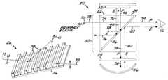
- FIG. 1is a schematic drawing of the situation awareness viewing device
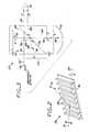
- FIG. 2is a perspective view of a wire grid polarizer
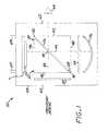
- FIG. 3is a ray path drawing for the polarized light components in the situation awareness viewing device.
- FIG. 1depicts a situation awareness viewing device 20 in the preferred form of a head-mounted unit that views a Primary Scene.
- the depicted Primary Scenemay be a directly viewed external scene (so that the situation awareness viewing device 20 is a see-through device), or it may be a generated display of the external scene such as an infrared image (so that the situation awareness viewing device 20 is not a see-through device).
- the situation awareness viewing device 20may be controllably alternated between a see-through configuration and a non-see-through configuration using a movable generated image source that may be selectively positioned at the location indicated as Primary Scene in FIG. 1 .
- the situation awareness viewing device 20includes a polarizing beam splitter 22 formed of a square parallelopiped, here depicted as and termed a cube 24 , of a material transparent to light, preferably visible light.
- a polarizing beam splitter 22formed of a square parallelopiped, here depicted as and termed a cube 24 , of a material transparent to light, preferably visible light.
- cube 24may be made of any transparent material such as glass or plastic.
- Such plasticsare available under the trademark Zeonex from Nippon Zeon Co., an example being Zeonex E48R.
- the cube 24is a frame containing air, a liquid, or other transparent substance having an optical power, and is thus termed an “air cube”. That is, in the second embodiment the wire grid polarizer, to be described next, is supported in the interior space of what is described as the cube 24 . In all cases, the material transparent to light has an index of refraction of greater than 1 (unity).
- the solid cube 24 of the first embodimentis preferred due to its more robust construction and its higher optical power, and it will be the primary subject of the following discussion.
- a wire grid polarizer 26lies within the cube 24 on an edge-to-edge cube-diagonal plane 28 extending between two diagonally opposed edges 30 and 32 of a square face of the cube 24 .
- the wire grid polarizer 26is a generally planar device that divides space into two portions, a first portion to a first side of the wire grid polarizer and a second portion to a second side of the wire grid polarizer. These sides of the wire grid polarizer may be used as references to describe the locations of features.
- the image source and external polarizer, to be described subsequently,are on the first side of the wire grid polarizer in the sense that they lie in the first portion of space to the first side of the wire grid polarizer.
- the quarter-wave plate, the mirror, and the eye of the user, to be described subsequently,are on the second side of the wire grid polarizer in the sense that they lie in the second portion of space to the second side of the wire grid polarizer. That an element lies “on a first side” or “on a second side” is only a relative reference to the position of the wire grid polarizer, and does not suggest that the element contacts the first side or the second side of the wire grid polarizer.
- the wire grid polarizer 26is formed of an array of parallel metallic stripes 34 supported on a glass, plastic, or other transparent, electrically nonconducting substrate 36 .
- Wire grid polarizers 26are known in the art for other applications and are described, for example, in U.S. Pat. No. 4,289,381, whose disclosure is incorporated by reference, and Bernd Schnabel et al., “Study on polarizing visible light by subwavelength-period metal-stripe gratings, Opt.Eng . Vol.38(2), pages 220-226 (February 1999).
- the wire grid polarizerpreferably comprises parallel aluminum metallic stripes on the glass substrate, with a spacing of about 150 nanometers.
- the wire grid polarizer 26has several operating characteristics of particular interest in the present application and which provide surprising and unexpected results in the present application.
- an incident beam 37 of lightis polarized by the wire grid polarizer 26 as a transmitted p-plane wave 39 and a reflected s-plane wave 41 , with a high degree of efficiency.
- There is little energy lost from the incident beam 37That is, the total of the energy in the waves 39 and 41 is nearly that of the incident beam 37 .
- This polarizing performanceis nearly independent of wavelength over the entire visible range, so that the wire grid polarizer 26 and the situation awareness viewing device 20 may be used either in monochrome or color applications.
- the polarizing performance of the wire grid polarizer 26is also retained over a wide range of angle of incidence of the incident beam 37 , so that the situation awareness viewing device 20 has a wide field of view of more than about 30 degrees and on the order of about 40 degrees (i.e.,+/ ⁇ 20 degrees) in the preferred construction.
- Thisis to be contrasted with other types of polarizing beam splitters.
- a MacNeille polarizing beam splitter utilizing a multi-layer dielectric stackhas polarizing performance that is limited to a narrow field of view of about +/ ⁇ 2 degrees before polarizing performance is degraded. Its polarization properties are dependent upon both angle of incidence and wavelength of the incident light, making it largely unsuitable for the present application of a situation awareness viewing device that requires a relatively wide field of view.
- the polarizing beam splitter 22is prepared by forming two 45 degree right-angle prisms of the transparent material.
- the wire grid polarizer 26is captured between the two prisms to form the rectangular parallelopiped, preferably in the form of the cube 24 .
- the wire grid polarizer 26is “immersed” between the two prisms, so that there is substantially no air gap between the wire grid polarizer 26 and the prisms, or between the two prisms, that would produce a mismatch in the index of refraction and lead to unwanted reflections.
- the preferred embodimenthas the metallic stripes of the wire grid polarizer oriented into the plane of the paper in FIGS. 1 and 3, but other orientations are possible.
- the polarizing beam splitter 22may be described as having a first optical axis 38 extending from a first face 40 of the cube 24 toward an opposing second face 42 of the cube 24 .
- the first optical axis 38lies at an angle of 45 degrees to the cube-diagonal plane 28 .
- a second optical axis 44extends from a third face 46 of the cube 24 toward an opposing fourth face 48 of the cube 24 .
- the second optical axis 44lies at an angle of 45 degrees to the cube-diagonal plane 28 .
- the second optical axis 44is perpendicular to the first optical axis 38 at a point of intersection 49 .
- An external polarizer 50is positioned external to the cube 24 .
- the external polarizer 50is disposed to intercept light incident in either direction upon the first face 40 along the first optical axis 38 .
- the external polarizer 50passes p-oriented light and absorbs s-oriented polarized light, with the polarizations defined by the optical axis of the polarizer.
- the preferred external polarizer 50is a Polaroid HN42HE thin film polarizer that permits only about 0.04 percent of the incident s-polarized light to pass therethrough.
- An image source 52is positioned external to the cube 24 .
- the image sourceis disposed to send a display image incident upon the third face 46 along the second optical axis 44 .
- the image source 52may be of any operable type, with a light-emitting diode (LED) source preferred.
- the image source 52is an active matrix organic light emitting diode (AMOLED), which is very efficient and of low power consumption to conserve the life of the battery that powers the image source 52 .
- AMOLEDactive matrix organic light emitting diode
- An important advantage of the present inventionis that the image source 52 may be a source of unpolarized light, such as the light emitting diode. The use of an unpolarized source is permitted by the operation of the other optical elements, particularly the use of the wire grid polarizer rather than another type of polarizer.
- the unpolarized light sourcehas a higher light output and brightness than a polarized light source, so that the image from the image source 52 reaching the eye of the user is relatively brighter. Consequently, special filters such as adjustable polarizers to reduce the intensity of the directly viewed scene are not needed and are not present in the preferred embodiment. If, on the other hand, the intensity of the viewed image from the image source 52 is relatively less bright, as is observed if the image source is a polarized light source such as a polarized liquid crystal display used in some prior devices, the viewed image from the image source 52 is difficult to see due to the much higher brightness of the directly viewed scene and some filter is typically required to reduce the brightness of the directly viewed scene. Such an additional filter adds complexity, weight, cost, and size to the device.
- a polarization direction changing deviceillustrated as a preferred quarter-wave plate 54 , is positioned on the second optical axis 44 on the opposite side of the intersection 49 from the image source 52 .
- the quarter-wave plate 54is disposed to intercept a beam of light traveling along the second optical axis 44 and passing out of the cube 24 through the fourth face 48 .
- this quarter-wave plate 54should be achromatic and zero order.
- a mirror 56is positioned on the second optical axis 44 with the quarter-wave plate 54 between the mirror 56 and the wire grid polarizer 26 .
- the mirror 56which is preferably a spherical or aspherical concave mirror that magnifies the incident display image, is disposed to reflect light passing through the quarter-wave plate 54 back through the quarter-wave plate 54 and to the fourth face 48 .
- Other mirror arrangements having a comparable optical effectmay be used.
- the present approachwas selected for compactness. Having passed through the quarter-wave plate 54 twice, the plane of light polarization has now rotated 90 degrees, such that it is now reflected by the wire grid polarizer onto the first optical path 38 and is directed to the eye 66 of the user.
- FIGS. 1 and 3show the elements 50 , 52 , 54 , and 56 as being separated from and spaced apart from the cube 24 , so as to clearly illustrate these elements.
- This embodimentmay be used, but in practice it is preferred that one or more, preferably all, of the elements 50 , 52 , 54 , and 56 be laminated or bonded, as with optical cement, to the respective faces of the cube 24 for robustness and for optical performance. Air gaps are eliminated as to those elements which are laminated to the cube 24 .
- the term “external” as used hereinencompasses these various embodiments. “External” is used to provide a reference relative to the cube and is consistent with both the presence and the absence of an air gap.
- the situation awareness viewing device 20also desirably includes a housing 58 that contains the components 24 , 26 , 50 , 52 , and 54 .
- the housing 58has openings 60 and 62 therethrough to respectively allow entry of a scene image from the primary scene and viewing by a user.
- a head mount 64supports the housing 58 and the contained components and positions them relative to the head of the user, here indicated by the user's eye 66 .
- the head mount 64may be of any operable type, such as the illustrated brackets that are affixed to a helmet, eyeglasses, visor, headband, and the like.
- FIG. 3which is similar to FIG. 1 but with the housing 58 removed, illustrates the ray paths and mode of functioning of the situation awareness viewing device 20 for a preferred embodiment.
- An incident light beam 70 from the primary scenecontains an s-polarized component 72 and a p-polarized component 74 .
- the s-polarized component 72is absorbed by and not transmitted through the p-oriented external polarizer 50 consistent with the polarizer's extinction ratio.
- the p-polarized component 74passes through the wire grid polarizer 26 and to the eye 66 of the user as the image of the primary scene that is viewed by the user.
- the display image produced by the image source 52may be described as having an s-polarized component 76 and a p-polarized component 78 .
- the p-polarized component 78passes through the wire grid polarizer 26 to the quarter-wave plate 54 , reflects from the mirror 56 , and again passes through the quarter-wave plate 54 .
- the quarter-wave plate 54converts the p-polarized component 78 to an s-polarized component 80 , which reflects from the wire grid polarizer 26 and to the eye 66 of the user as the viewed component of the display image.
- the s-polarized component 76 from the image source 52reflects from the wire grid polarizer 26 toward the primary scene. Unless prevented from passing out of the situation awareness viewing device 20 , this reflected s-polarized component 76 would be projected forwardly and could be used by an opponent to locate and target the user.
- the p-oriented external polarizer 50prevents the s-polarized component 76 from passing out of the situation awareness viewing device 20 , so that the situation awareness viewing device 20 has a low observability characteristic.
- the Polaroid HN42HE thin film polarizerpermits only 0.04 percent of the light to escape in the forward direction outwardly from the situation awareness viewing device 20 , resulting in very low observability.
Landscapes
- Physics & Mathematics (AREA)
- General Physics & Mathematics (AREA)
- Optics & Photonics (AREA)
- Polarising Elements (AREA)
Abstract
Description
Claims (25)
Priority Applications (4)
| Application Number | Priority Date | Filing Date | Title |
|---|---|---|---|
| US09/774,495US6693749B2 (en) | 2001-01-31 | 2001-01-31 | Low-observability, wide-field-of-view, situation awareness viewing device |
| AU2002240328AAU2002240328A1 (en) | 2001-01-31 | 2002-01-30 | Low-observability, wide-field-of-view, situation awareness viewing device |
| PCT/US2002/003932WO2002061490A2 (en) | 2001-01-31 | 2002-01-30 | Low-observability, wide-field-of-view, situation awareness viewing device |
| EP02706225AEP1356337A2 (en) | 2001-01-31 | 2002-01-30 | Low-observability, wide-field-of-view, situation awareness viewing device |
Applications Claiming Priority (1)
| Application Number | Priority Date | Filing Date | Title |
|---|---|---|---|
| US09/774,495US6693749B2 (en) | 2001-01-31 | 2001-01-31 | Low-observability, wide-field-of-view, situation awareness viewing device |
Publications (2)
| Publication Number | Publication Date |
|---|---|
| US20020101664A1 US20020101664A1 (en) | 2002-08-01 |
| US6693749B2true US6693749B2 (en) | 2004-02-17 |
Family
ID=25101425
Family Applications (1)
| Application Number | Title | Priority Date | Filing Date |
|---|---|---|---|
| US09/774,495Expired - LifetimeUS6693749B2 (en) | 2001-01-31 | 2001-01-31 | Low-observability, wide-field-of-view, situation awareness viewing device |
Country Status (4)
| Country | Link |
|---|---|
| US (1) | US6693749B2 (en) |
| EP (1) | EP1356337A2 (en) |
| AU (1) | AU2002240328A1 (en) |
| WO (1) | WO2002061490A2 (en) |
Cited By (49)
| Publication number | Priority date | Publication date | Assignee | Title |
|---|---|---|---|---|
| US20040207927A1 (en)* | 2003-04-18 | 2004-10-21 | Takayoshi Togino | Eyepiece optical system, and display device using the eyepiece optical system |
| US20060098293A1 (en)* | 2004-09-08 | 2006-05-11 | John Garoutte | Wearable display system |
| US20070252953A1 (en)* | 2006-04-27 | 2007-11-01 | Robert Metzger | Crosstalk reduced stereoscopic viewing apparatus |
| US20110013146A1 (en)* | 2008-04-07 | 2011-01-20 | Nobuhiro Fujinawa | Illumination apparatus and projector |
| US20110214082A1 (en)* | 2010-02-28 | 2011-09-01 | Osterhout Group, Inc. | Projection triggering through an external marker in an augmented reality eyepiece |
| US20110221793A1 (en)* | 2010-02-28 | 2011-09-15 | Osterhout Group, Inc. | Adjustable display characteristics in an augmented reality eyepiece |
| US20110273771A1 (en)* | 2009-01-13 | 2011-11-10 | Canon Kabushiki Kaisha | Optical element |
| US20130070338A1 (en)* | 2011-09-21 | 2013-03-21 | Google Inc. | Lightweight eyepiece for head mounted display |
| US8467133B2 (en) | 2010-02-28 | 2013-06-18 | Osterhout Group, Inc. | See-through display with an optical assembly including a wedge-shaped illumination system |
| US8472120B2 (en) | 2010-02-28 | 2013-06-25 | Osterhout Group, Inc. | See-through near-eye display glasses with a small scale image source |
| US8477425B2 (en) | 2010-02-28 | 2013-07-02 | Osterhout Group, Inc. | See-through near-eye display glasses including a partially reflective, partially transmitting optical element |
| US8482859B2 (en) | 2010-02-28 | 2013-07-09 | Osterhout Group, Inc. | See-through near-eye display glasses wherein image light is transmitted to and reflected from an optically flat film |
| US8488246B2 (en) | 2010-02-28 | 2013-07-16 | Osterhout Group, Inc. | See-through near-eye display glasses including a curved polarizing film in the image source, a partially reflective, partially transmitting optical element and an optically flat film |
| US8508851B2 (en) | 2011-07-20 | 2013-08-13 | Google Inc. | Compact see-through display system |
| US8593732B1 (en)* | 2010-01-23 | 2013-11-26 | Lightsmyth Technologies, Inc. | Partially metallized total internal reflection immersion grating |
| US8670000B2 (en) | 2011-09-12 | 2014-03-11 | Google Inc. | Optical display system and method with virtual image contrast control |
| US8767305B2 (en) | 2011-08-02 | 2014-07-01 | Google Inc. | Method and apparatus for a near-to-eye display |
| US8767306B1 (en) | 2011-09-22 | 2014-07-01 | Google Inc. | Display system |
| US8823740B1 (en) | 2011-08-15 | 2014-09-02 | Google Inc. | Display system |
| US8860831B1 (en)* | 2013-02-21 | 2014-10-14 | Exelis, Inc. | Brightness tracking light sensor |
| US8941560B2 (en) | 2011-09-21 | 2015-01-27 | Google Inc. | Wearable computer with superimposed controls and instructions for external device |
| US20150070596A1 (en)* | 2013-09-06 | 2015-03-12 | Omnivision Technologies, Inc. | Eyewear display system providing vision enhancement |
| US9069115B2 (en) | 2013-04-25 | 2015-06-30 | Google Inc. | Edge configurations for reducing artifacts in eyepieces |
| US9087471B2 (en) | 2011-11-04 | 2015-07-21 | Google Inc. | Adaptive brightness control of head mounted display |
| US9091851B2 (en) | 2010-02-28 | 2015-07-28 | Microsoft Technology Licensing, Llc | Light control in head mounted displays |
| US9097891B2 (en) | 2010-02-28 | 2015-08-04 | Microsoft Technology Licensing, Llc | See-through near-eye display glasses including an auto-brightness control for the display brightness based on the brightness in the environment |
| US9097890B2 (en) | 2010-02-28 | 2015-08-04 | Microsoft Technology Licensing, Llc | Grating in a light transmissive illumination system for see-through near-eye display glasses |
| US9129295B2 (en) | 2010-02-28 | 2015-09-08 | Microsoft Technology Licensing, Llc | See-through near-eye display glasses with a fast response photochromic film system for quick transition from dark to clear |
| US9128281B2 (en) | 2010-09-14 | 2015-09-08 | Microsoft Technology Licensing, Llc | Eyepiece with uniformly illuminated reflective display |
| US9134534B2 (en) | 2010-02-28 | 2015-09-15 | Microsoft Technology Licensing, Llc | See-through near-eye display glasses including a modular image source |
| US9182596B2 (en) | 2010-02-28 | 2015-11-10 | Microsoft Technology Licensing, Llc | See-through near-eye display glasses with the optical assembly including absorptive polarizers or anti-reflective coatings to reduce stray light |
| US9223134B2 (en) | 2010-02-28 | 2015-12-29 | Microsoft Technology Licensing, Llc | Optical imperfections in a light transmissive illumination system for see-through near-eye display glasses |
| US9229227B2 (en) | 2010-02-28 | 2016-01-05 | Microsoft Technology Licensing, Llc | See-through near-eye display glasses with a light transmissive wedge shaped illumination system |
| US9239415B2 (en) | 2012-03-08 | 2016-01-19 | Google Inc. | Near-to-eye display with an integrated out-looking camera |
| US9285589B2 (en) | 2010-02-28 | 2016-03-15 | Microsoft Technology Licensing, Llc | AR glasses with event and sensor triggered control of AR eyepiece applications |
| US9341843B2 (en) | 2010-02-28 | 2016-05-17 | Microsoft Technology Licensing, Llc | See-through near-eye display glasses with a small scale image source |
| US9366862B2 (en) | 2010-02-28 | 2016-06-14 | Microsoft Technology Licensing, Llc | System and method for delivering content to a group of see-through near eye display eyepieces |
| US9759917B2 (en) | 2010-02-28 | 2017-09-12 | Microsoft Technology Licensing, Llc | AR glasses with event and sensor triggered AR eyepiece interface to external devices |
| US9791696B2 (en) | 2015-11-10 | 2017-10-17 | Microsoft Technology Licensing, Llc | Waveguide gratings to improve intensity distributions |
| US9915825B2 (en) | 2015-11-10 | 2018-03-13 | Microsoft Technology Licensing, Llc | Waveguides with embedded components to improve intensity distributions |
| US20180136473A1 (en)* | 2016-01-22 | 2018-05-17 | Corning Incorporated | Wide field personal display |
| US10180572B2 (en) | 2010-02-28 | 2019-01-15 | Microsoft Technology Licensing, Llc | AR glasses with event and user action control of external applications |
| US10261328B2 (en) | 2016-09-02 | 2019-04-16 | Microsoft Technology Licensing, Llc | Enhanced illumination system |
| US10359627B2 (en) | 2015-11-10 | 2019-07-23 | Microsoft Technology Licensing, Llc | Waveguide coatings or substrates to improve intensity distributions having adjacent planar optical component separate from an input, output, or intermediate coupler |
| US10539787B2 (en) | 2010-02-28 | 2020-01-21 | Microsoft Technology Licensing, Llc | Head-worn adaptive display |
| US10802184B2 (en) | 2014-04-28 | 2020-10-13 | Ii-Vi Delaware Inc. | Reflective diffraction gratings employing efficiency enhancement or etch barrier layers |
| US10860100B2 (en) | 2010-02-28 | 2020-12-08 | Microsoft Technology Licensing, Llc | AR glasses with predictive control of external device based on event input |
| US10976551B2 (en) | 2017-08-30 | 2021-04-13 | Corning Incorporated | Wide field personal display device |
| EP3712682A4 (en)* | 2017-12-04 | 2021-06-09 | Huawei Technologies Co., Ltd. | DEVICE, OPTICAL MOTOR COMPONENT AND AUGMENTED REALITY PROCESS |
Families Citing this family (7)
| Publication number | Priority date | Publication date | Assignee | Title |
|---|---|---|---|---|
| JP2003215344A (en) | 2001-03-29 | 2003-07-30 | Seiko Epson Corp | Polarizer and optical device using the polarizer |
| US7085050B2 (en)* | 2001-12-13 | 2006-08-01 | Sharp Laboratories Of America, Inc. | Polarized light beam splitter assembly including embedded wire grid polarizer |
| KR102069024B1 (en) | 2015-09-03 | 2020-01-22 | 쓰리엠 이노베이티브 프로퍼티즈 컴파니 | Optical system |
| GB2570302A (en) | 2018-01-17 | 2019-07-24 | Wave Optics Ltd | Light projector |
| US11506898B1 (en)* | 2019-09-30 | 2022-11-22 | Snap Inc. | Polarized reflective pinhole mirror display |
| CN111273453B (en)* | 2020-01-10 | 2022-09-13 | 南京理工大学 | Polarization multiplexing-based large-field-of-view imaging device and method |
| CN111487786A (en)* | 2020-04-26 | 2020-08-04 | 京东方科技集团股份有限公司 | Optical display system, control method, and display device |
Citations (15)
| Publication number | Priority date | Publication date | Assignee | Title |
|---|---|---|---|---|
| US4012671A (en)* | 1975-10-14 | 1977-03-15 | Gulf & Western Industries, Inc. | Trigger circuit |
| US4289381A (en) | 1979-07-02 | 1981-09-15 | Hughes Aircraft Company | High selectivity thin film polarizer |
| US5245472A (en)* | 1991-06-26 | 1993-09-14 | Hughes Aircraft Company | High-efficiency, low-glare X-prism |
| EP0566004A2 (en) | 1992-04-07 | 1993-10-20 | Hughes Aircraft Company | Virtual image display having a high efficiency grid beamsplitter |
| US5289434A (en)* | 1992-09-18 | 1994-02-22 | Shell Oil Company | Retroreflector apparatus for remote seismic sensing |
| US5357372A (en)* | 1992-04-07 | 1994-10-18 | Hughes Aircraft Company | Ultra-compact, wide field of view virtual image display optical system |
| US5467205A (en)* | 1993-04-28 | 1995-11-14 | Olympus Optical Co., Ltd. | Image display system with right and left eye illuminating means |
| US5526184A (en)* | 1992-12-10 | 1996-06-11 | Olympus Optical Co., Ltd. | Head-mounted display apparatus for observing an outside world image and/or a display image |
| US5581271A (en)* | 1994-12-05 | 1996-12-03 | Hughes Aircraft Company | Head mounted visual display |
| US5598296A (en)* | 1994-06-01 | 1997-01-28 | Olympus Optical Co., Ltd. | Prismatic telescope optical system |
| EP0825470A1 (en) | 1996-03-11 | 1998-02-25 | Seiko Epson Corporation | Head-mounted display |
| US5828489A (en)* | 1996-04-12 | 1998-10-27 | Rockwell International Corporation | Narrow wavelength polarizing beamsplitter |
| US5880889A (en)* | 1997-02-26 | 1999-03-09 | Raytheon Company | Three color dichroic beamsplitter for separating or combining unpolarized light |
| US6108131A (en)* | 1998-05-14 | 2000-08-22 | Moxtek | Polarizer apparatus for producing a generally polarized beam of light |
| US6243199B1 (en) | 1999-09-07 | 2001-06-05 | Moxtek | Broad band wire grid polarizing beam splitter for use in the visible wavelength region |
- 2001
- 2001-01-31USUS09/774,495patent/US6693749B2/ennot_activeExpired - Lifetime
- 2002
- 2002-01-30EPEP02706225Apatent/EP1356337A2/ennot_activeWithdrawn
- 2002-01-30AUAU2002240328Apatent/AU2002240328A1/ennot_activeAbandoned
- 2002-01-30WOPCT/US2002/003932patent/WO2002061490A2/ennot_activeApplication Discontinuation
Patent Citations (16)
| Publication number | Priority date | Publication date | Assignee | Title |
|---|---|---|---|---|
| US4012671A (en)* | 1975-10-14 | 1977-03-15 | Gulf & Western Industries, Inc. | Trigger circuit |
| US4289381A (en) | 1979-07-02 | 1981-09-15 | Hughes Aircraft Company | High selectivity thin film polarizer |
| US5245472A (en)* | 1991-06-26 | 1993-09-14 | Hughes Aircraft Company | High-efficiency, low-glare X-prism |
| EP0566004A2 (en) | 1992-04-07 | 1993-10-20 | Hughes Aircraft Company | Virtual image display having a high efficiency grid beamsplitter |
| US5357372A (en)* | 1992-04-07 | 1994-10-18 | Hughes Aircraft Company | Ultra-compact, wide field of view virtual image display optical system |
| US5383053A (en) | 1992-04-07 | 1995-01-17 | Hughes Aircraft Company | Virtual image display having a high efficiency grid beamsplitter |
| US5289434A (en)* | 1992-09-18 | 1994-02-22 | Shell Oil Company | Retroreflector apparatus for remote seismic sensing |
| US5526184A (en)* | 1992-12-10 | 1996-06-11 | Olympus Optical Co., Ltd. | Head-mounted display apparatus for observing an outside world image and/or a display image |
| US5467205A (en)* | 1993-04-28 | 1995-11-14 | Olympus Optical Co., Ltd. | Image display system with right and left eye illuminating means |
| US5598296A (en)* | 1994-06-01 | 1997-01-28 | Olympus Optical Co., Ltd. | Prismatic telescope optical system |
| US5581271A (en)* | 1994-12-05 | 1996-12-03 | Hughes Aircraft Company | Head mounted visual display |
| EP0825470A1 (en) | 1996-03-11 | 1998-02-25 | Seiko Epson Corporation | Head-mounted display |
| US5828489A (en)* | 1996-04-12 | 1998-10-27 | Rockwell International Corporation | Narrow wavelength polarizing beamsplitter |
| US5880889A (en)* | 1997-02-26 | 1999-03-09 | Raytheon Company | Three color dichroic beamsplitter for separating or combining unpolarized light |
| US6108131A (en)* | 1998-05-14 | 2000-08-22 | Moxtek | Polarizer apparatus for producing a generally polarized beam of light |
| US6243199B1 (en) | 1999-09-07 | 2001-06-05 | Moxtek | Broad band wire grid polarizing beam splitter for use in the visible wavelength region |
Non-Patent Citations (2)
| Title |
|---|
| Bernd Schnabel et al., Study on polarizing visible light by subwavelength-period metal-stripe gratings, Opt.Eng. vol. 38(2), pp. 220-226 (Feb. 1999). |
| Schnabel B. et al.: "Study on Polarizing Visible Light by Subwavelength-Period Metal-Stripe Gratings", Optical Engineering, Soc, of Photo-Optical, Feb. 99. |
Cited By (67)
| Publication number | Priority date | Publication date | Assignee | Title |
|---|---|---|---|---|
| US7009775B2 (en)* | 2003-04-18 | 2006-03-07 | Olympus Corporation | Eyepiece optical system, and display device using the eyepiece optical system |
| US20040207927A1 (en)* | 2003-04-18 | 2004-10-21 | Takayoshi Togino | Eyepiece optical system, and display device using the eyepiece optical system |
| US7589902B2 (en)* | 2004-09-08 | 2009-09-15 | Concurrent Technologies Corporation | Method of combining images in a wearable display system |
| US20060098293A1 (en)* | 2004-09-08 | 2006-05-11 | John Garoutte | Wearable display system |
| US20080013185A1 (en)* | 2004-09-08 | 2008-01-17 | Concurrent Technologies Corporation | Method of combining images in a wearable display system |
| US7545571B2 (en)* | 2004-09-08 | 2009-06-09 | Concurrent Technologies Corporation | Wearable display system |
| US20070252953A1 (en)* | 2006-04-27 | 2007-11-01 | Robert Metzger | Crosstalk reduced stereoscopic viewing apparatus |
| US20110013146A1 (en)* | 2008-04-07 | 2011-01-20 | Nobuhiro Fujinawa | Illumination apparatus and projector |
| US8459798B2 (en)* | 2008-04-07 | 2013-06-11 | Nikon Corporation | Illumination apparatus and projector |
| US9097906B2 (en)* | 2009-01-13 | 2015-08-04 | Canon Kabushiki Kaisha | Optical element |
| US20110273771A1 (en)* | 2009-01-13 | 2011-11-10 | Canon Kabushiki Kaisha | Optical element |
| US9297937B1 (en) | 2010-01-23 | 2016-03-29 | Lightsmyth Technologies, Inc. | Partially metallized total internal reflection immersion grating |
| US8593732B1 (en)* | 2010-01-23 | 2013-11-26 | Lightsmyth Technologies, Inc. | Partially metallized total internal reflection immersion grating |
| US9097891B2 (en) | 2010-02-28 | 2015-08-04 | Microsoft Technology Licensing, Llc | See-through near-eye display glasses including an auto-brightness control for the display brightness based on the brightness in the environment |
| US20110221793A1 (en)* | 2010-02-28 | 2011-09-15 | Osterhout Group, Inc. | Adjustable display characteristics in an augmented reality eyepiece |
| US8477425B2 (en) | 2010-02-28 | 2013-07-02 | Osterhout Group, Inc. | See-through near-eye display glasses including a partially reflective, partially transmitting optical element |
| US8482859B2 (en) | 2010-02-28 | 2013-07-09 | Osterhout Group, Inc. | See-through near-eye display glasses wherein image light is transmitted to and reflected from an optically flat film |
| US8488246B2 (en) | 2010-02-28 | 2013-07-16 | Osterhout Group, Inc. | See-through near-eye display glasses including a curved polarizing film in the image source, a partially reflective, partially transmitting optical element and an optically flat film |
| US20110214082A1 (en)* | 2010-02-28 | 2011-09-01 | Osterhout Group, Inc. | Projection triggering through an external marker in an augmented reality eyepiece |
| US8467133B2 (en) | 2010-02-28 | 2013-06-18 | Osterhout Group, Inc. | See-through display with an optical assembly including a wedge-shaped illumination system |
| US9285589B2 (en) | 2010-02-28 | 2016-03-15 | Microsoft Technology Licensing, Llc | AR glasses with event and sensor triggered control of AR eyepiece applications |
| US9341843B2 (en) | 2010-02-28 | 2016-05-17 | Microsoft Technology Licensing, Llc | See-through near-eye display glasses with a small scale image source |
| US10860100B2 (en) | 2010-02-28 | 2020-12-08 | Microsoft Technology Licensing, Llc | AR glasses with predictive control of external device based on event input |
| US8814691B2 (en) | 2010-02-28 | 2014-08-26 | Microsoft Corporation | System and method for social networking gaming with an augmented reality |
| US9229227B2 (en) | 2010-02-28 | 2016-01-05 | Microsoft Technology Licensing, Llc | See-through near-eye display glasses with a light transmissive wedge shaped illumination system |
| US10539787B2 (en) | 2010-02-28 | 2020-01-21 | Microsoft Technology Licensing, Llc | Head-worn adaptive display |
| US10268888B2 (en) | 2010-02-28 | 2019-04-23 | Microsoft Technology Licensing, Llc | Method and apparatus for biometric data capture |
| US10180572B2 (en) | 2010-02-28 | 2019-01-15 | Microsoft Technology Licensing, Llc | AR glasses with event and user action control of external applications |
| US8472120B2 (en) | 2010-02-28 | 2013-06-25 | Osterhout Group, Inc. | See-through near-eye display glasses with a small scale image source |
| US9875406B2 (en) | 2010-02-28 | 2018-01-23 | Microsoft Technology Licensing, Llc | Adjustable extension for temple arm |
| US9759917B2 (en) | 2010-02-28 | 2017-09-12 | Microsoft Technology Licensing, Llc | AR glasses with event and sensor triggered AR eyepiece interface to external devices |
| US9223134B2 (en) | 2010-02-28 | 2015-12-29 | Microsoft Technology Licensing, Llc | Optical imperfections in a light transmissive illumination system for see-through near-eye display glasses |
| US9091851B2 (en) | 2010-02-28 | 2015-07-28 | Microsoft Technology Licensing, Llc | Light control in head mounted displays |
| US9366862B2 (en) | 2010-02-28 | 2016-06-14 | Microsoft Technology Licensing, Llc | System and method for delivering content to a group of see-through near eye display eyepieces |
| US9097890B2 (en) | 2010-02-28 | 2015-08-04 | Microsoft Technology Licensing, Llc | Grating in a light transmissive illumination system for see-through near-eye display glasses |
| US9329689B2 (en) | 2010-02-28 | 2016-05-03 | Microsoft Technology Licensing, Llc | Method and apparatus for biometric data capture |
| US9129295B2 (en) | 2010-02-28 | 2015-09-08 | Microsoft Technology Licensing, Llc | See-through near-eye display glasses with a fast response photochromic film system for quick transition from dark to clear |
| US9182596B2 (en) | 2010-02-28 | 2015-11-10 | Microsoft Technology Licensing, Llc | See-through near-eye display glasses with the optical assembly including absorptive polarizers or anti-reflective coatings to reduce stray light |
| US9134534B2 (en) | 2010-02-28 | 2015-09-15 | Microsoft Technology Licensing, Llc | See-through near-eye display glasses including a modular image source |
| US9128281B2 (en) | 2010-09-14 | 2015-09-08 | Microsoft Technology Licensing, Llc | Eyepiece with uniformly illuminated reflective display |
| US9091850B2 (en) | 2011-07-20 | 2015-07-28 | Google Inc. | Compact see-through display system |
| US8508851B2 (en) | 2011-07-20 | 2013-08-13 | Google Inc. | Compact see-through display system |
| US8767305B2 (en) | 2011-08-02 | 2014-07-01 | Google Inc. | Method and apparatus for a near-to-eye display |
| US8823740B1 (en) | 2011-08-15 | 2014-09-02 | Google Inc. | Display system |
| US8670000B2 (en) | 2011-09-12 | 2014-03-11 | Google Inc. | Optical display system and method with virtual image contrast control |
| US9013793B2 (en)* | 2011-09-21 | 2015-04-21 | Google Inc. | Lightweight eyepiece for head mounted display |
| US8941560B2 (en) | 2011-09-21 | 2015-01-27 | Google Inc. | Wearable computer with superimposed controls and instructions for external device |
| US20130070338A1 (en)* | 2011-09-21 | 2013-03-21 | Google Inc. | Lightweight eyepiece for head mounted display |
| US9678654B2 (en) | 2011-09-21 | 2017-06-13 | Google Inc. | Wearable computer with superimposed controls and instructions for external device |
| US8767306B1 (en) | 2011-09-22 | 2014-07-01 | Google Inc. | Display system |
| US9087471B2 (en) | 2011-11-04 | 2015-07-21 | Google Inc. | Adaptive brightness control of head mounted display |
| US9239415B2 (en) | 2012-03-08 | 2016-01-19 | Google Inc. | Near-to-eye display with an integrated out-looking camera |
| US8860831B1 (en)* | 2013-02-21 | 2014-10-14 | Exelis, Inc. | Brightness tracking light sensor |
| US9069115B2 (en) | 2013-04-25 | 2015-06-30 | Google Inc. | Edge configurations for reducing artifacts in eyepieces |
| US9658454B2 (en)* | 2013-09-06 | 2017-05-23 | Omnivision Technologies, Inc. | Eyewear display system providing vision enhancement |
| US20150070596A1 (en)* | 2013-09-06 | 2015-03-12 | Omnivision Technologies, Inc. | Eyewear display system providing vision enhancement |
| US10802184B2 (en) | 2014-04-28 | 2020-10-13 | Ii-Vi Delaware Inc. | Reflective diffraction gratings employing efficiency enhancement or etch barrier layers |
| US9791696B2 (en) | 2015-11-10 | 2017-10-17 | Microsoft Technology Licensing, Llc | Waveguide gratings to improve intensity distributions |
| US10359627B2 (en) | 2015-11-10 | 2019-07-23 | Microsoft Technology Licensing, Llc | Waveguide coatings or substrates to improve intensity distributions having adjacent planar optical component separate from an input, output, or intermediate coupler |
| US9915825B2 (en) | 2015-11-10 | 2018-03-13 | Microsoft Technology Licensing, Llc | Waveguides with embedded components to improve intensity distributions |
| US10120194B2 (en)* | 2016-01-22 | 2018-11-06 | Corning Incorporated | Wide field personal display |
| US10649210B2 (en) | 2016-01-22 | 2020-05-12 | Corning Incorporated | Wide field personal display |
| US20180136473A1 (en)* | 2016-01-22 | 2018-05-17 | Corning Incorporated | Wide field personal display |
| US10261328B2 (en) | 2016-09-02 | 2019-04-16 | Microsoft Technology Licensing, Llc | Enhanced illumination system |
| US10976551B2 (en) | 2017-08-30 | 2021-04-13 | Corning Incorporated | Wide field personal display device |
| EP3712682A4 (en)* | 2017-12-04 | 2021-06-09 | Huawei Technologies Co., Ltd. | DEVICE, OPTICAL MOTOR COMPONENT AND AUGMENTED REALITY PROCESS |
| US11269186B2 (en) | 2017-12-04 | 2022-03-08 | Huawei Technologies Co., Ltd. | Augmented reality apparatus and method, and optical engine component |
Also Published As
| Publication number | Publication date |
|---|---|
| AU2002240328A1 (en) | 2002-08-12 |
| WO2002061490A2 (en) | 2002-08-08 |
| US20020101664A1 (en) | 2002-08-01 |
| EP1356337A2 (en) | 2003-10-29 |
| WO2002061490A3 (en) | 2003-02-20 |
Similar Documents
| Publication | Publication Date | Title |
|---|---|---|
| US6693749B2 (en) | Low-observability, wide-field-of-view, situation awareness viewing device | |
| CN112654902B (en) | Head Mounted Display (HMD) with spatially varying phase shifter optics | |
| US9194995B2 (en) | Compact illumination module for head mounted display | |
| US8767305B2 (en) | Method and apparatus for a near-to-eye display | |
| US7482996B2 (en) | Head-up display | |
| US7242524B2 (en) | Optical system for forming a real image in space | |
| US9013793B2 (en) | Lightweight eyepiece for head mounted display | |
| US6563638B2 (en) | Wide-angle collimating optical device | |
| US11181815B1 (en) | Optical devices including reflective spatial light modulators for projecting augmented reality content | |
| US10969675B1 (en) | Optical assemblies having scanning reflectors for projecting augmented reality content | |
| JPH10507534A (en) | Optical path extender for small image display system | |
| CN111630417A (en) | Light projector | |
| EP4130851A1 (en) | Optical apparatus and head-mounted device | |
| US10690926B1 (en) | Near-eye augmented reality device | |
| US6282029B1 (en) | Compact display system | |
| KR101129372B1 (en) | Ophthalmic display comprising an ophthalmic lens and an optical image | |
| US10539796B1 (en) | Systems and methods to provide privacy protection and brightness enhancement in an interactive environment | |
| CN220855351U (en) | AR/VR dual-mode display system and device | |
| KR20200019157A (en) | Dot sighting device having a beam splitter |
Legal Events
| Date | Code | Title | Description |
|---|---|---|---|
| AS | Assignment | Owner name:RAYTHEON COMAPNY, CALIFORNIA Free format text:DOCUMENT PREVIOUSLY RECORDED AT REEL 011797 FRAME 0881 CONTAINED AN ERROR IN PROPERTY NUMBER 09/556216. DOCUMENT RERECORDED TO CORRECT ERROR ON STATED REEL.;ASSIGNORS:KING, WILLIAM B.;CHEN, CHUNGTE W.;HEGG, RONALD G.;AND OTHERS;REEL/FRAME:012537/0378;SIGNING DATES FROM 20010329 TO 20010426 | |
| STCF | Information on status: patent grant | Free format text:PATENTED CASE | |
| FEPP | Fee payment procedure | Free format text:PAYOR NUMBER ASSIGNED (ORIGINAL EVENT CODE: ASPN); ENTITY STATUS OF PATENT OWNER: LARGE ENTITY | |
| FPAY | Fee payment | Year of fee payment:4 | |
| FPAY | Fee payment | Year of fee payment:8 | |
| AS | Assignment | Owner name:OL SECURITY LIMITED LIABILITY COMPANY, DELAWARE Free format text:ASSIGNMENT OF ASSIGNORS INTEREST;ASSIGNOR:RAYTHEON COMPANY;REEL/FRAME:029117/0335 Effective date:20120730 | |
| FEPP | Fee payment procedure | Free format text:PAYOR NUMBER ASSIGNED (ORIGINAL EVENT CODE: ASPN); ENTITY STATUS OF PATENT OWNER: LARGE ENTITY Free format text:PAYER NUMBER DE-ASSIGNED (ORIGINAL EVENT CODE: RMPN); ENTITY STATUS OF PATENT OWNER: LARGE ENTITY | |
| FPAY | Fee payment | Year of fee payment:12 | |
| AS | Assignment | Owner name:INTELLECTUAL VENTURES ASSETS 186 LLC, DELAWARE Free format text:ASSIGNMENT OF ASSIGNORS INTEREST;ASSIGNOR:OL SECURITY LIMITED LIABILITY COMPANY;REEL/FRAME:062756/0114 Effective date:20221222 | |
| AS | Assignment | Owner name:INTELLECTUAL VENTURES ASSETS 186 LLC, DELAWARE Free format text:SECURITY INTEREST;ASSIGNOR:MIND FUSION, LLC;REEL/FRAME:063295/0001 Effective date:20230214 Owner name:INTELLECTUAL VENTURES ASSETS 191 LLC, DELAWARE Free format text:SECURITY INTEREST;ASSIGNOR:MIND FUSION, LLC;REEL/FRAME:063295/0001 Effective date:20230214 | |
| AS | Assignment | Owner name:MIND FUSION, LLC, WASHINGTON Free format text:ASSIGNMENT OF ASSIGNORS INTEREST;ASSIGNOR:INTELLECTUAL VENTURES ASSETS 186 LLC;REEL/FRAME:064271/0001 Effective date:20230214 |