US6693738B2 - Broadband amplifier and communication system - Google Patents
Broadband amplifier and communication systemDownload PDFInfo
- Publication number
- US6693738B2 US6693738B2US09/990,142US99014201AUS6693738B2US 6693738 B2US6693738 B2US 6693738B2US 99014201 AUS99014201 AUS 99014201AUS 6693738 B2US6693738 B2US 6693738B2
- Authority
- US
- United States
- Prior art keywords
- raman amplifier
- transmission line
- wdm wavelengths
- dispersion
- optical signal
- Prior art date
- Legal status (The legal status is an assumption and is not a legal conclusion. Google has not performed a legal analysis and makes no representation as to the accuracy of the status listed.)
- Expired - Lifetime
Links
Images


Classifications
- H—ELECTRICITY
- H04—ELECTRIC COMMUNICATION TECHNIQUE
- H04B—TRANSMISSION
- H04B10/00—Transmission systems employing electromagnetic waves other than radio-waves, e.g. infrared, visible or ultraviolet light, or employing corpuscular radiation, e.g. quantum communication
- H04B10/29—Repeaters
- H04B10/291—Repeaters in which processing or amplification is carried out without conversion of the main signal from optical form
- H—ELECTRICITY
- H01—ELECTRIC ELEMENTS
- H01S—DEVICES USING THE PROCESS OF LIGHT AMPLIFICATION BY STIMULATED EMISSION OF RADIATION [LASER] TO AMPLIFY OR GENERATE LIGHT; DEVICES USING STIMULATED EMISSION OF ELECTROMAGNETIC RADIATION IN WAVE RANGES OTHER THAN OPTICAL
- H01S3/00—Lasers, i.e. devices using stimulated emission of electromagnetic radiation in the infrared, visible or ultraviolet wave range
- H01S3/30—Lasers, i.e. devices using stimulated emission of electromagnetic radiation in the infrared, visible or ultraviolet wave range using scattering effects, e.g. stimulated Brillouin or Raman effects
- H01S3/302—Lasers, i.e. devices using stimulated emission of electromagnetic radiation in the infrared, visible or ultraviolet wave range using scattering effects, e.g. stimulated Brillouin or Raman effects in an optical fibre
- H—ELECTRICITY
- H04—ELECTRIC COMMUNICATION TECHNIQUE
- H04B—TRANSMISSION
- H04B10/00—Transmission systems employing electromagnetic waves other than radio-waves, e.g. infrared, visible or ultraviolet light, or employing corpuscular radiation, e.g. quantum communication
- H04B10/29—Repeaters
- H04B10/291—Repeaters in which processing or amplification is carried out without conversion of the main signal from optical form
- H04B10/2912—Repeaters in which processing or amplification is carried out without conversion of the main signal from optical form characterised by the medium used for amplification or processing
- H04B10/2916—Repeaters in which processing or amplification is carried out without conversion of the main signal from optical form characterised by the medium used for amplification or processing using Raman or Brillouin amplifiers
- H—ELECTRICITY
- H01—ELECTRIC ELEMENTS
- H01S—DEVICES USING THE PROCESS OF LIGHT AMPLIFICATION BY STIMULATED EMISSION OF RADIATION [LASER] TO AMPLIFY OR GENERATE LIGHT; DEVICES USING STIMULATED EMISSION OF ELECTROMAGNETIC RADIATION IN WAVE RANGES OTHER THAN OPTICAL
- H01S3/00—Lasers, i.e. devices using stimulated emission of electromagnetic radiation in the infrared, visible or ultraviolet wave range
- H01S3/10—Controlling the intensity, frequency, phase, polarisation or direction of the emitted radiation, e.g. switching, gating, modulating or demodulating
- H01S3/106—Controlling the intensity, frequency, phase, polarisation or direction of the emitted radiation, e.g. switching, gating, modulating or demodulating by controlling devices placed within the cavity
- H01S3/108—Controlling the intensity, frequency, phase, polarisation or direction of the emitted radiation, e.g. switching, gating, modulating or demodulating by controlling devices placed within the cavity using non-linear optical devices, e.g. exhibiting Brillouin or Raman scattering
- H01S3/1083—Controlling the intensity, frequency, phase, polarisation or direction of the emitted radiation, e.g. switching, gating, modulating or demodulating by controlling devices placed within the cavity using non-linear optical devices, e.g. exhibiting Brillouin or Raman scattering using parametric generation
- H—ELECTRICITY
- H04—ELECTRIC COMMUNICATION TECHNIQUE
- H04B—TRANSMISSION
- H04B2210/00—Indexing scheme relating to optical transmission systems
- H04B2210/25—Distortion or dispersion compensation
- H04B2210/258—Distortion or dispersion compensation treating each wavelength or wavelength band separately
Definitions
- the present inventionrelates generally to broadband amplifiers and communication systems, and more particularly to broadband booster amplifiers and communication systems with Raman and rare-earth doped amplifiers.
- WDMwavelength-division multiplexing
- Optical amplifiersboost the signal strength and compensate for inherent fiber loss and other splitting and insertion losses.
- WDMenables different wavelengths of light to carry different signals parallel over the same optical fiber.
- VDMis critical in that it allows utilization of a major fraction of the fiber bandwidth, it would not be cost-effective without optical amplifiers.
- a broadband optical amplifierthat permits simultaneous amplification of many WDM channels is a key enabler for utilizing the full fiber bandwidth.
- Silica-based optical fiberhas its lowest loss window around 1550 nm with approximately 25 THz of bandwidth between 1430 and 1620 nm.
- erbium-doped fiber amplifiersEDFAs
- the absorption band of a EDFAnearly overlaps its the emission band.
- erbium-atoms in typical glasseswill absorb more than amplify.
- various dopingshave been added. Co-doping of the silica core with aluminum or phosphorus broadens the emission spectrum considerably. Nevertheless, the absorption peak for the various glasses is still around 1530 nm.
- a two-band architecture for an ultra-wideband EDFAhas been developed with an optical bandwidth of 80 mn. To obtain a low noise figure and high output power, the two bands share a common first gain section and have distinct second gain sections.
- the 80nm bandwidthcomes from one amplifier (so-called conventional band or C-band) from 1525.6 to 1562.5 nm and another amplifier (so-called long band or L-band) from 1569.4 to 1612.8 nm.
- an object of the present inventionis to provide a method of broadband amplification that divides an optical signal with a wavelength of 1430 nm to 1620 nm at a preselected wavelength into a first beam and a second beam.
- Another object of the present inventionis to provide a method of broadband communication that propagates a plurality of WDM wavelengths, with at least a portion of the WDM wavelengths in the range of 1430 to 1530 nm, from a trnsrmitter assembly along a transmission line.
- Yet another object of the present inventionis to provide a method of broadband communication that propagates a first plurality of WDM wavelengths in the wavelength range of 1530 to 1620 from a transmitter assembly along a transmission line, and introduces a second plurality of WDM wavelengths in the wavelength range of 1430 to 1530 to the transmission line.
- a method of broadband amplificationdivides an optical signal of wavelength of 1430 nm to 1620 nm at a preselected wavelength into a first beam and a second beam.
- the first beamis directed to at least one optical amplifier and produces an amplified first beam.
- the second beamis directed to at least one rare earth doped fiber amplifier to produce an amplified second beam.
- the first and second amplified beamsare combined.
- a method transmitting WDM wavelengths in a broadband communication systemincludes propagating a plurality of WDM wavelengths from a transmitter assembly along a transmission line. At least a portion of the WDM wavelengths are in the wavelength range of 1430 to 1530 nm. At least a portion of the plurality of wavelengths are amplified with a Raman amplifier assembly to create a plurality of amplified WDM wavelengths. The plurality of amplified WDM wavelengths are received at a receiver assembly.
- a method of transmitting WDM wavelengthspropagates a first plurality of WDM wavelengths in the wavelength range of 1530 to 1620 from a transmitter assembly along a transmission line.
- a second plurality of WDM wavelengths in the wavelength range of 1130 to 1530is introduced to the transmission line;
- the second plurality of WDM wavelengthsare amplified by Raman amplification after the second plurality of WDM wavelengths are introduced to the transmission line.
- the first and second pluralities of WDM wavelengthsare received at a receiver assembly.
- a method of transmitting WVDM wavelengths in a broadband communication systemincludes, propagating a plurality of WDM wavelengths from a transmitter assembly along a transmission line. At least a portion of the plurality of WDM wavelengths are in the wavelength range of 1430 to 1530 nm. A portion of the plurality of wavelengths are amplified with a Raman amplifier assembly to create a plurality of amplified WDM wavelengths that are received at a receiver assembly.
- a method of transmitting WDM wavelengths in a broadband communication svstemincludes propagating a first plurality of WDM wavelengths in the wavelength range of 1530 to 1620 from a transmitter assembly along a transmission line. A second plurality of WDM wavelengths in the wavelength range of 1430 to 1530 are introduced to the transmission line. The second plurality of WDM wavelengths are amplified by Raman amplification after the second plurality of WDM wavelengths are introduced to the transmission line. The first and second pluralities of WDM wavelengths are received at a receiver assembly.
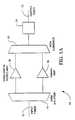
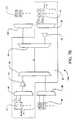
- FIG. 1 ( a )is a schematic diagram of one embodiment of a broadband amplifier of the present invention with a parallel geometric combination of Raman and rare-earth doped amplifiers.
- FIG. 1 ( b )is a schematic diagram of another embodiment of a broadband amplifier of the present invention with a parallel geometric combination of Raman and rare-earth doped amplifiers.
- FIG. 2 ( a )is a graph illustrating that transmission of any two bands from the parallel geometric combinations of the Raman and rare-earth amplifiers of FIGS. 1 ( a ) and 1 ( b ) is a function of wavelength of combiners splitters.
- FIG. 2 ( b )is a graph illustrating that transmission of the C or L band and the S band from the parallel geometric combinations of the Raman and rare-earth amplifiers of FIGS. 1 ( a ) and 1 ( b ) is a function of wavelength of combiners splitters.
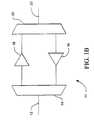
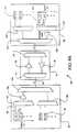
- FIG. 3 ( a )is a schematic diagram of one embodiment of a broadband booster amplifier of the present invention.
- FIG. 3 ( b )is a schematic diagram of another embodiment of a broadband booster amplifier of the present invention.
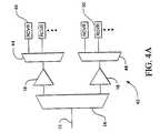
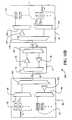
- FIG. 4 ( a )is a schematic diagram of one embodiment of a broadband pre-amplifier of the present invention.
- FIG. 4 ( b )is a schematic diagram of another embodiment of a broadband pre-amplifier of the present invention.
- FIGS. 5 ( a ) through 11 ( b )are schematic diagrams illustrating different embodiments of broadband communication systems of the present invention.
- the present inventionprovides parallel optical amplification with a combination of optical amplifiers.
- This parallel optical amplificationcan include two parallel stages of Raman and rareearth doped optical amplifiers.
- Amplifier 10(FIG. 1 ( a )) and amplifier 11 (FIG. 1 ( b )) each include at least one input fiber 12 coupled to a splitter 14 .
- splittersinclude WDM couplers, fused tapered couplers, Mach-Zehnder interferometers, gratings and circulators, and the like.
- Splitter 14divides an optical signal having a wavelength between 1430nm and 1620 nm at a predetermined wavelength, preferably at 1525 nm, into at least a first wavelength and a second wavelength.
- a Raman amplifier 16 and a rare-earth doped optical amplifier 18are coupled to splitter 14 and arranged in a parallel manner.
- Raman amplifier 16receives the first band and produces an amplified broadband first band.
- Rare-earth doped optical amplifier 18receives the second band and produces an amplified broadband second band.
- a combiner 20is coupled to Raman amplifier 16 and rare-earth doped optical amplifier 18 .
- Combiner 20combines the amplified and spectrally broadened first and second bands to produce an amplified broadband optical signal.
- a transition from a stop band to a pass band of combiner 20occurs in preferably 20 nm or less, more preferably 15 nm or less and most preferably 10 nm or less.
- An output fiber 22is coupled to combiner 20 .
- Preferably splitter 14 and combiner 20are WDM couplers.
- An output fiber 22is coupled to combiner 20 .
- input fiber 12transmits at least a first wavelength and a second wavelength.
- the first wavelengthfalls within a gain bandwidth of Raman amplifier 16 and the second wavelength falls within a gain bandwidth of rare-earth doped optical amplifier 18 .
- a gain tilt control device 24can be coupled to splitter 14 , Raman amplifier 16 , rare-earth doped optical amplifier 18 or combiner 20 .
- Suitable gain tilt control devices 24include but are not limited to adjustable gain flattening filters, long period gratings, cascaded Mach-Zehnder filters, acousto-optic filter devices and the like.
- Raman amplifier 16 and rare-earth doped amplifier 18are arranged so that the first and second bands co-propagate
- Raman amplifier 16 and rare-earth doped amplifier 18are arranged so that the first and second bands are counter-propagating. The counter-propagating reduces interaction between the first and second bands.
- FIGS. 2 ( a ) and 2 ( b )illustrate that in parallel geometric combinations of Raman amplifier 16 and rare-earth doped amplifier 18 transmission of the two bands is a finction of wavelength of combiner 20 and splitter 14 .
- FIG. 2 ( a )is generic for any two bands while FIG. 2 ( b ) is specific to the S and C/L bands.
- FIGS. 3 ( a ) and 3 ( b )illustrate broadband booster amplifier 30 embodiments of the present invention that include a first plurality of transmitters 32 that emits a first pluraiity of wavelengths, and a second plurality of transmitters 34 that transmit a second band of wavelengths.
- Raman amplifier 16is coupled to the second plurality of transmitters 34 through a combiner 38 .
- Raman amplifier 16amplifies the first band of wavelengths.
- Rare-earth doped optical amplifier 18is coupled to the plurality of transmitters 32 through a combiner 36 .
- Rare-earth doped optical amplifier 18amplifies the second band of wavelengths.
- Combiner 20is coupled to Raman amplifier 16 and rare-earth doped optical amplifier 18 .
- Combiner 20combines an optical signal from Raman amplifier 16 and rareo earth doped amplifier 18 into at least a first wavelength and a second wavelength.
- a transition from a stop band to a pass band of combiner 20occurs preferably in 20 nm or less, more preferably 15 nm or less and still more preferably 10 nm or less.
- Output fiber 22is coupled to combiner 20 .
- Gain tilt control device 24can be coupled to Raman amplifier 16 , rare-earth doped optical amplifier 18 or combiner 20 .
- rare-earth doped amplifier 18is coupled to combiner 20 .
- Raman amplifier 16is coupled to a combiner 40 .
- Raman amplifier 16 and rare-earth doped amplifier 18are arranged so that the first and second bands co-propagate
- Raman amplifier 16 and rare-earth doped amplifier 18are arranged so that the first and second bands are counter-propagating.
- FIGS. 4 ( a ) and 4 ( b )illustrate broadband pre-amplifier 42 embodiments of the present invention that include at least one input fiber 12 coupled to splitter 14 .
- Splitter 14splits an optical signal into at least a first wavelength and a second wavelength, wherein a transition from a stop band to a pass band of the splitter occurs preferably in 20 nm or less, more preferably 15 nm or less and still more preferably in 10 nm or less.
- Raman amplifier 16 and rare-earth doped optical amplifierare coupled to splitter 14 .
- a splitter 44is coupled to a first plurality of receivers 46 and rare-earth doped optical amplifier 18 .
- a splitter 48is coupled to a second plurality of receivers 50 and Raman amplifier 18 .
- rare-earth doped amplifier 18is coupled to combiner 20 .
- Raman amplifier 16is coupled to combiner 52 .
- Raman amplifier 16 and rare-earth doped amplifier 18are arranged so that the first and second bands co-propagate
- Raman amplifier 16 and rare-earth doped amplifier 18are arranged so that the first and second bands are counter-propagating.
- Raman amplifier 16can be optimized for wavelengths between 1430 to 1530 nm.
- Rare-earth doped optical amplifier 18can be optimized for wavelengths between 1530 to 1620 nm.
- Rare-earth doped optical amplifier 18is preferably doped with erbium, thulium, telluride, preseodenium.
- Additional elementscan be included with any of the amplifiers 10 and 11 of FIG. 1 ( a ) through FIG. 4 ( b ).
- Such elementsinclude but not limited to gain equalizers, add/drop multiplexers, dispersion compensating elements and the like, all of which can be positioned in and around the amplifier.
- Suitable gain equalizersinclude but are not limited to long period gratings, Mach-Zehnder interferometer filters, dielectric filters and the like.
- Suitable add/drop multiplexersinclude but are not limited to gratings and circulators, gratings in Mach-Zehnder interferometers and dielectric filters.
- Suitable dispersion compensating elementsinclude but are not limited chirped gratings and circulators and dispersion compensating fibers.
- Amplifiers 10 and 11can be included in multi-stage sub-systems, have more than two amplifiers in parallel configurations and be discrete or distributed amplifiers.
- the present inventionis also a broadband communication system.
- amplifiers 10 and 11can be coupled with any type of transmitter and receiver.
- broadband communication sn stem 54includes a transmitter 56 coupled to input fiber 12 .
- a receiver 58is coupled to output fiber 22 which in turn is coupled to combiner 20 .
- Transmitter 56can be a semiconductor laser as well as other types of lasers and devices that emit wavelengths.
- Receiver 58can be a detector coupled with electronic circuitry.
- Raman amplifier 16 and rare-earth doped optical amplifier 18are arranged so that the first and second bands co-propagate, while in FIG. 5 ( b ) they are arranged so that the first and second bands counter-propagate.
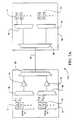
- FIGS. 6 ( a ) and 6 ( b )illustrate other embodiments of broadband communication systems 60 and 62 , respectively with in-line amplifiers coupled to transmitter and receiver assemblies.
- Broadband communication system 60includes broadband amplifier 10 coupled to a transmitter assembly 64 and a receiver assembly 66 .
- Transmitter assembly 64includes a first plurality of transmitters 68 that emits a first band of wavelengths, and a second plurality of transmitters 70 that transmit a second band of wavelengths each coupled to a combiner 72 and 74 , respectively.
- the first and second bandsco-propagate.
- Combiners 72 and 74in turn are coupled to a combiner 76 .
- Combiner 76is coupled to broadband amplifier 10 .
- Receiver assembly 66includes a first plurality of receivers 78 and a second plurality of receivers 80 , each coupled to a splitter 82 and 84 , respectively.
- Splitters 82 and 84are coupled to a splitter 86 which is then coupled to broadband amplifier 10 .
- amplifier 11is coupled to a transmitter/receiver assembly 88 and a transmitter receiver assembly 90 .
- Transmitter/receiver assembly 88includes a first plurality of transmitters 92 coupled to a combiner 94 .
- First plurality of transmitters 92emits a first band of wavelengths.
- a first plurality of receivers 96is coupled to a splitter 98 .
- Combiner 94 and splitter 98are coupled to a combiner 100 which in turn is coupled to amplifier 11 .
- Transmitter/receiver assembly 90includes a second plurality of receivers 102 coupled to a splitter 104 and a second plurality of transmitters 106 that transmit a second band of wavelengths.
- Second plurality of transmitters 106is coupled to a combiner 108 .
- Splitter 104 and combiner 108are coupled to a splitter 110 which in turn is coupled to broadband amplifier 11 .
- broadband amplifier 11In the embodiment of FIG. 6 ( b ) the two bands counter-propagate.
- booster amplifiersare connected to a transmission line and a receiver assembly.
- a broadband communication system 112illustrated in FIG. 7 ( a ) includes broadband booster amplifier 30 coupled to receiver assembly 66 .
- the first and second bandsco-propagate.
- Broadband communication system 114illustrated in FIG. 7 ( b ) includes broadband booster amplifier 30 coupled to splitter 98 and splitter 104 .
- First plurality of receivers 96is coupled to splitter 98 .
- Second plurality of receivers 102is coupled to splitter 104 .
- Splitter 98is coupled to combiner 20
- splitter 104is coupled to combiner 40 .
- the two bands of broadband communication system 114counter-propagate.
- FIGS. 8 ( a ) and 8 ( b )illustrate pre-amplifiers connected to a transmission line and a transmitter assembly.
- Broadband communication system 116illustrated in FIG. 8 ( a ) includes transmitter assembly 64 which is coupled to broadband pre-amplifier 42 .
- the first and second bandco-propagate.
- Broadband communication system 118illustrated in FIG. 8 ( b ) includes first plurality of transmitters 120 which transmit a first band of wavelengths.
- First plurality of transmitters 120is coupled to a combiner 122 .
- a second plurality of transmitters 124transmit a second band of wavelengths.
- Second plurality of transmitters 124is coupled to combiner 126 .
- Combiner 122 and combiner 126are each coupled to broadband pre-amplifier 42 .
- the two bandscounter-propagate with broadband communication system 118 .
- Broadband communication system 128illustrated in FIG. 9 ( a ), includes a booster/amplifier assembly 130 and receiver assembly 66 , each coupled to amplifier 10 .
- Booster/amplifier assembly 130includes a first plurality of transmitters 132 , a combiner 134 , a rare-earth doped amplifier 136 , a second plurality of transmitters 138 , a combiner 140 , a Raman amplifier 142 and a combiner 144 .
- First plurality of transmitters 132emits a first band of wavelengths
- second plurality of transmitters 138emits a second band of wavelengths.
- the first and second band of wavelengthsco-propagate.
- Combiner 144 and splitter 86are each coupled to amplifier 10 .
- Broadband communication system 146illustrated in FIG. 9 ( b ), includes a rare-earth doped amplifier 148 coupled to transmitter/receiver assembly 88 . Also included is a Raman amplifier 150 coupled to transmitter/receiver assembly 90 . Combiner 100 and splitter 110 are each coupled to amplifier 11 . The first and second bands counter-propagate with broadband communication system 146 .
- pre-amplifiers and in-line amplifiersare connected to transmission lines and transmitter assemblies.
- a broadband communication system 152includes transmitter assembly 64 and a receiver assembly 154 that are both coupled to amplifier 10 .
- Receiver assembly 154includes a splitter 156 , a rare-earth doped amplifier 158 , a Raman amplifier 160 , splitters 162 and 164 as well as first and second pluralities of receivers 166 and 168 .
- Rare-earth doped amplifier 158is coupled to splitters 156 and 162 .
- Raman amplifier 160is coupled to splitters 156 and 164 . The first and second bands co-propagate.
- Broadband communication svstem 170illustrated in FIG. 10 ( b ). includes a Raman amplifier 172 coupled to transmitter/receiver assembly 88 .
- Raman amplifier 172is coupled to splitter 98 and combiner 100 .
- a rare earth doped optical amplifier 174is coupled to transmitter/receiver assembly 90 .
- Rare-earth doped optical amplifier 174is coupled to splitters 104 and 110 .
- Splitter 110 and combiner 100are each coupled to amplifier 11 .
- the first and second bandscounter-propagate.
- Broadband communication system 176illustrated in FIG. 11 ( a ), includes a rare-earth doped amplifier 178 and a Raman amplifier 180 that are coupled to transmitter assembly 64 .
- Rare-earth doped amplifier 178is coupled to combiners 72 and 76 .
- Raman amplifier 180is coupled to combiners 74 and 76 .
- Combiner 76is coupled to splitter 14 of amplifier 10 .
- Receiver assembly 154is coupled to combiner 20 of amplifier 10 .
- a rare-earth doped amplifier 182 and a Raman amplifier 184are coupled to receiver assembly 66 .
- Rare-earth doped optical amplifier 182is coupled to splitters 86 and 82 .
- Raman amplifier 184is coupled to splitters 84 and 86 .
- Splitter 86 and combiner 76are coupled to amplifier 10 .
- the first and second bandsco-propagate.
- a broadband communication system 186includes a rare-earth doped optical amplifier 178 and Raman amplifier 180 coupled to transmitter/receiver assembly 88 .
- Rare-earth doped optical amplifier 178is coupled to combiners 94 and 100 .
- Raman amplifier 180is coupled to splitter 98 and combiner 100 .
- Rare-earth doped amplifier 182 and Raman amplifier 184are coupled to transmitter/receiver assembly 90 .
- Rare-earth doped optical amplifieris coupled to splitters 104 and 110 .
- Raman amplifier 184is coupled to combiner 108 and splitter 110 .
- Splitter 110 and combiner 100are coupled to amplifier 11 .
- the first and second bandscounter-propagate.
- the broadband communication systems illustrated in FIGS. 5 ( a ) through 11 ( b )can employ a variety of different optical fibers including but not limited to standard fiber, DSF, non-zero dispersion shifted fiber (NZ-DSF), and the like.
- Standard fiberhas a zero dispersion wavelength near 1310 nm.
- the zero dispersion wavelength of DSFis near 1550 nm.
- NZ-DSFhas different zero dispersion wavelengths, depending on the manufacturer.
- the broadband communication systems of the present inventioncan designed to be dispersion managed systems with fibers that have different amounts of dispersion spliced together to make a system that has locally high dispersion and globally low dispersion.
- broadband communication systems of the present inventionhave utility in undersea cable systems, wide area networks (WAN), metropolitan area networks (MAN) and local area networks (LAN). Switches, cross-connects, routers, restoration switches and add/drop multiplexers can be included with any of the broadband communication systems of the present invention.
- WANwide area networks
- MANmetropolitan area networks
- LANlocal area networks
- the present inventionis also a method of broadband amplification that uses any of the FIG. 1 ( a ) through FIG. 11 ( b ) amplifiers or systems.
- an optical signal of wavelength of 1430 nm to 1620 nmis divided at a preselected wavelength into a first beam and a second beam.
- the first beamis directed to at least one optical amplifier and produces an amplified first beam.
- the second beamis directed to at least one rare earth doped fiber amplifier to produce an amplified second beam.
- the first and second amplified beamsare combined.
- a method of transmitting WDM wavelengthsin any of the FIG. 5 ( a ) through FIG. 11 ( b ) broadband communication systems, includes propagating a plurality of WDM wavelengths from a transmitter assembly along a trnmission line. At least a portion of the WDM wavelengths are in the wavelength range of 1430 to 1530 nm. At least a portion of the plurality of wavelengths are amplified with a Raman amplifier assembly to create a plurality of amplified WDM wavelengths. The plurality of amplified WDM wavelengths are received at a receiver assembly. At least a portion of the WDM wavelengths can be in the wavelength range of 1530 to 1570 nm, 1570 to 1630 nm or both.
- a method of transmitting WDM wavelengthsin any of the FIG. 5 ( a ) through FIG. 11 ( b ) broadband communication systems, propagates a first plurality of WDM wavelengths in the wavelength range of 1530 to 1620 from a transmitter assembly along a transmission line.
- a second plurality of WDM wavelengths in the wavelength range of 1430 to 1530is introduced to the transmission line.
- the second plurality of WDM wavelengthsare amplified by Raman amplification after the second plurality of WDM wavelengths are introduced to the transmission line.
- the first and second pluralities of WDM wavelengthsare received at a receiver assembly.
- a method of transmitting WDM wavelengthsin any of the FIG. 5 ( a ) through FIG. 11 ( b ) broadband communication systems, propagates a plurality of WDM wavelengths from a transmitter assembly along a transmission line. At least a portion of the plurality of WDM wavelengths are in the wavelength range of 1430 to 1530 nm. A portion of the plurality of wavelengths are amplified with a Raman amplifier assembly to create a plurality of amplified WDM wavelengths that are received at a receiver assembly.
- a method of transmitting WDM wavelengthsin any of the FIG. 5 ( a ) through FIG. 11 ( b ) broadband communication systems.
- a second plurality of WDM wavelengths in the wavelength range of 1430 to 1530are introduced to the transmission line.
- the second plurality of WDM wavelengthsare amplified by Raman amplification after the second plurality of WDM wavelengths are introduced to the transmission line.
- the first and second pluralities of WDM wavelengthsare received at a receiver assembly.
- the transmission linecan be coupled to a Raman amplifier assembly that Raman amplifies the second plurality of WDM wavelengths.
- the transmissioncan have a magnitude of dispersion of at least 5 ps/(nm)(km), be in the range of 1-5 ps/(nm)(kmn) or be less than 1 ps/(nm)(km).
- Raman amplifier assemblies of the methods of the present inventioncan include a discrete Raman amplifier inserted into the transmission line.
- the Raman amplifier assemblycan include a distributed Raman amplifier and a discrete Raman amplifier.
- the Raman amplifier assemblycan include a dispersion compensating fiber with a magnitude of dispersion of at least 50 ps/(nm)(km). At least a portion of the gain of the Raman amplifier assembly can be in the dispersion compensating fiber.
Landscapes
- Physics & Mathematics (AREA)
- Electromagnetism (AREA)
- Engineering & Computer Science (AREA)
- Computer Networks & Wireless Communication (AREA)
- Signal Processing (AREA)
- Plasma & Fusion (AREA)
- Optics & Photonics (AREA)
- Optical Modulation, Optical Deflection, Nonlinear Optics, Optical Demodulation, Optical Logic Elements (AREA)
- Optical Communication System (AREA)
- Lasers (AREA)
- Light Guides In General And Applications Therefor (AREA)
Abstract
Description
Claims (80)
Priority Applications (1)
| Application Number | Priority Date | Filing Date | Title |
|---|---|---|---|
| US09/990,142US6693738B2 (en) | 1998-03-24 | 2001-11-20 | Broadband amplifier and communication system |
Applications Claiming Priority (5)
| Application Number | Priority Date | Filing Date | Title |
|---|---|---|---|
| US09/046,900US6101024A (en) | 1998-03-24 | 1998-03-24 | Nonlinear fiber amplifiers used for a 1430-1530nm low-loss window in optical fibers |
| US47175299A | 1999-12-23 | 1999-12-23 | |
| US47083199A | 1999-12-23 | 1999-12-23 | |
| US09/547,165US6356384B1 (en) | 1998-03-24 | 2000-04-11 | Broadband amplifier and communication system |
| US09/990,142US6693738B2 (en) | 1998-03-24 | 2001-11-20 | Broadband amplifier and communication system |
Related Parent Applications (1)
| Application Number | Title | Priority Date | Filing Date |
|---|---|---|---|
| US09/547,165ContinuationUS6356384B1 (en) | 1998-03-24 | 2000-04-11 | Broadband amplifier and communication system |
Publications (2)
| Publication Number | Publication Date |
|---|---|
| US20020051285A1 US20020051285A1 (en) | 2002-05-02 |
| US6693738B2true US6693738B2 (en) | 2004-02-17 |
Family
ID=24183577
Family Applications (3)
| Application Number | Title | Priority Date | Filing Date |
|---|---|---|---|
| US09/547,165Expired - LifetimeUS6356384B1 (en) | 1998-03-24 | 2000-04-11 | Broadband amplifier and communication system |
| US10/003,199Expired - LifetimeUS6580548B2 (en) | 1998-03-24 | 2001-10-30 | Broadband amplifier and communication system |
| US09/990,142Expired - LifetimeUS6693738B2 (en) | 1998-03-24 | 2001-11-20 | Broadband amplifier and communication system |
Family Applications Before (2)
| Application Number | Title | Priority Date | Filing Date |
|---|---|---|---|
| US09/547,165Expired - LifetimeUS6356384B1 (en) | 1998-03-24 | 2000-04-11 | Broadband amplifier and communication system |
| US10/003,199Expired - LifetimeUS6580548B2 (en) | 1998-03-24 | 2001-10-30 | Broadband amplifier and communication system |
Country Status (5)
| Country | Link |
|---|---|
| US (3) | US6356384B1 (en) |
| EP (1) | EP1275213A2 (en) |
| AU (1) | AU2001255346A1 (en) |
| CA (1) | CA2409251A1 (en) |
| WO (1) | WO2001078263A2 (en) |
Cited By (4)
| Publication number | Priority date | Publication date | Assignee | Title |
|---|---|---|---|---|
| US20030133183A1 (en)* | 2001-08-15 | 2003-07-17 | Photon-X, Inc. | Ultra-wide bandwidth optical amplifier |
| US20050220397A1 (en)* | 2004-03-31 | 2005-10-06 | Fujitsu Limited | Coarse wavelength division multiplexing optical transmission system, and coarse wavelength division multiplexing optical transmission method |
| US20060188263A1 (en)* | 2002-03-15 | 2006-08-24 | Islam Mohammed N | System and Method for Dispersion Compensation in an Optical Communication System |
| US20070188851A1 (en)* | 2002-03-15 | 2007-08-16 | Xtera Communications, Inc. | System and Method for Managing System Margin |
Families Citing this family (94)
| Publication number | Priority date | Publication date | Assignee | Title |
|---|---|---|---|---|
| US6914717B1 (en) | 1996-12-23 | 2005-07-05 | Xtera Communications, Inc. | Multiple wavelength pumping of raman amplifier stages |
| US6052393A (en)* | 1996-12-23 | 2000-04-18 | The Regents Of The University Of Michigan | Broadband Sagnac Raman amplifiers and cascade lasers |
| US6693737B2 (en) | 1998-03-24 | 2004-02-17 | Xtera Communications, Inc. | Dispersion compensating nonlinear polarization amplifiers |
| US6760148B2 (en) | 1998-03-24 | 2004-07-06 | Xtera Communications, Inc. | Nonlinear polarization amplifiers in nonzero dispersion shifted fiber |
| US6600592B2 (en)* | 1998-03-24 | 2003-07-29 | Xtera Communications, Inc. | S+ band nonlinear polarization amplifiers |
| US6101024A (en) | 1998-03-24 | 2000-08-08 | Xtera Communications, Inc. | Nonlinear fiber amplifiers used for a 1430-1530nm low-loss window in optical fibers |
| US6356384B1 (en)* | 1998-03-24 | 2002-03-12 | Xtera Communications Inc. | Broadband amplifier and communication system |
| US6597493B2 (en) | 2000-05-05 | 2003-07-22 | The Regents Of The University Of Michigan | Nonlinear fiber amplifiers used for a 1430-1530nm low-loss window in optical fibers |
| US6631028B1 (en) | 1998-03-24 | 2003-10-07 | Xtera Communications, Inc. | Broadband amplifier and communication system |
| US6574037B2 (en) | 1998-06-16 | 2003-06-03 | Xtera Communications, Inc. | All band amplifier |
| US6885498B2 (en) | 1998-06-16 | 2005-04-26 | Xtera Communications, Inc. | Multi-stage optical amplifier and broadband communication system |
| US6335820B1 (en) | 1999-12-23 | 2002-01-01 | Xtera Communications, Inc. | Multi-stage optical amplifier and broadband communication system |
| JP5069825B2 (en) | 1998-06-16 | 2012-11-07 | エクステラ コミュニケイションズ インコーポレイテッド | Optical fiber compensation for dispersion, gain tilt, and band-pumping nonlinearity |
| US6359725B1 (en) | 1998-06-16 | 2002-03-19 | Xtera Communications, Inc. | Multi-stage optical amplifier and broadband communication system |
| US6618192B2 (en) | 1998-06-16 | 2003-09-09 | Xtera Communications, Inc. | High efficiency raman amplifier |
| US6567430B1 (en) | 1998-09-21 | 2003-05-20 | Xtera Communications, Inc. | Raman oscillator including an intracavity filter and amplifiers utilizing same |
| WO2001022626A1 (en)* | 1999-09-23 | 2001-03-29 | Alcatel | Amplification for optical fibre ultrawide band transmission systems |
| ATE443359T1 (en) | 2000-01-12 | 2009-10-15 | Xtera Communications Inc | DOUBLE-SIDE PUMPED RAMAN AMPLIFIER |
| DE20115473U1 (en) | 2001-09-19 | 2003-02-20 | Biester, Klaus, 29342 Wienhausen | Universal energy supply system |
| US7615893B2 (en)* | 2000-05-11 | 2009-11-10 | Cameron International Corporation | Electric control and supply system |
| DE20115474U1 (en) | 2001-09-19 | 2003-02-20 | Biester, Klaus, 29342 Wienhausen | DC converter device |
| DE20115471U1 (en) | 2001-09-19 | 2003-02-20 | Biester, Klaus, 29342 Wienhausen | Universal energy supply system |
| DE20018560U1 (en)* | 2000-10-30 | 2002-03-21 | CAMERON GmbH, 29227 Celle | Control and supply system |
| US6744553B1 (en) | 2000-06-20 | 2004-06-01 | Xtera Communications, Inc. | System and method for converting a plurality of wavelengths |
| US6697575B1 (en)* | 2000-06-30 | 2004-02-24 | Tyco Telecommunications (Us) Inc. | System and method for increasing capacity of long-haul optical transmission systems |
| WO2002007270A2 (en)* | 2000-07-14 | 2002-01-24 | Tycom (Us) Inc. | Hybrid fiber amplifier |
| US6417959B1 (en)* | 2000-12-04 | 2002-07-09 | Onetta, Inc. | Raman fiber amplifier |
| US6532101B2 (en) | 2001-03-16 | 2003-03-11 | Xtera Communications, Inc. | System and method for wide band Raman amplification |
| US6810214B2 (en)* | 2001-03-16 | 2004-10-26 | Xtera Communications, Inc. | Method and system for reducing degradation of optical signal to noise ratio |
| US20020163685A1 (en)* | 2001-05-01 | 2002-11-07 | Swanson Eric Arthur | System and method for routing working and protect paths |
| US6587259B2 (en) | 2001-07-27 | 2003-07-01 | Xtera Communications, Inc. | System and method for controlling noise figure |
| US6943936B2 (en)* | 2001-08-03 | 2005-09-13 | The Regents Of The University Of Michigan | Co-propagating Raman amplifiers |
| US6924926B2 (en) | 2001-08-03 | 2005-08-02 | Xtera Communications, Inc. | Laser diode pump sources |
| US6501597B1 (en)* | 2001-08-07 | 2002-12-31 | Spectralane, Inc. | Optical amplifier using wavelength converter |
| DE20115475U1 (en)* | 2001-09-19 | 2003-02-20 | Biester, Klaus, 29342 Wienhausen | DC converter device |
| US7020271B2 (en)* | 2003-06-12 | 2006-03-28 | Barbara Isabel Hummel | Ring control device |
| US6594071B1 (en) | 2001-10-02 | 2003-07-15 | Xtera Communications, Inc. | Method and apparatus for amplifier control |
| US7196840B2 (en)* | 2001-11-29 | 2007-03-27 | Broadband Royalty Corporation | Amplitude balancing for multilevel signal transmission |
| US6751371B1 (en)* | 2001-12-06 | 2004-06-15 | Xtera Communications, Inc. | Method and apparatus for optical element management |
| US7136585B2 (en)* | 2001-12-14 | 2006-11-14 | Kiribati Wireless Ventures, Llc | Optical amplifiers in a free space laser communication system |
| JP2003188831A (en)* | 2001-12-20 | 2003-07-04 | Fujitsu Ltd | Optical transmission system and optical repeater |
| US6819479B1 (en) | 2001-12-20 | 2004-11-16 | Xtera Communications, Inc. | Optical amplification using launched signal powers selected as a function of a noise figure |
| US6825973B1 (en) | 2002-03-15 | 2004-11-30 | Xtera Communications, Inc. | Reducing leading edge transients using co-propagating pumps |
| US6778321B1 (en) | 2002-03-15 | 2004-08-17 | Xtera Communications, Inc. | Fiber optic transmission system for a metropolitan area network |
| US6819478B1 (en) | 2002-03-15 | 2004-11-16 | Xtera Communications, Inc. | Fiber optic transmission system with low cost transmitter compensation |
| US7068938B1 (en) | 2002-03-15 | 2006-06-27 | Xtera Communications, Inc. | Band optical add/drop multiplexing |
| AU2003222112A1 (en)* | 2002-03-28 | 2003-10-13 | Celion Networks, Inc. | Apparatus and method for aggregation and transportation for plesiosynchronous framing oriented data formats |
| WO2003084082A2 (en)* | 2002-03-29 | 2003-10-09 | Celion Networks, Inc. | Distributed terminal optical transmission system |
| US7164692B2 (en)* | 2002-04-08 | 2007-01-16 | Jeffrey Lloyd Cox | Apparatus and method for transmitting 10 Gigabit Ethernet LAN signals over a transport system |
| US6965738B2 (en)* | 2002-04-16 | 2005-11-15 | Eiselt Michael H | Chromatic dispersion compensation system and method |
| WO2003090035A2 (en)* | 2002-04-22 | 2003-10-30 | Celion Networks, Inc. | Automated optical transport system |
| US6847678B2 (en)* | 2002-04-25 | 2005-01-25 | Raytheon Company | Adaptive air interface waveform |
| AU2003231190A1 (en)* | 2002-04-30 | 2003-11-17 | Celion Networks, Inc. | Optical transport system architecture for remote terminal connectivity |
| US8494372B2 (en) | 2002-04-30 | 2013-07-23 | Pivotal Decisions Llc | Apparatus and method for optimizing optical and electrical filtering of optical signals |
| US7460296B2 (en)* | 2002-04-30 | 2008-12-02 | Pivotal Decisions Llc | Compensation for spectral power tilt from scattering |
| US7206516B2 (en)* | 2002-04-30 | 2007-04-17 | Pivotal Decisions Llc | Apparatus and method for measuring the dispersion of a fiber span |
| US7711271B2 (en)* | 2002-04-30 | 2010-05-04 | Eiselt Michael H | Wave division multiplexed optical transport system utilizing optical circulators to isolate an optical service channel |
| US7603042B2 (en)* | 2002-06-04 | 2009-10-13 | Eiselt Michael H | Apparatus and method for optimum decision threshold setting |
| US6920277B2 (en) | 2002-06-04 | 2005-07-19 | Marvin R. Young | Optical bypass method and architecture |
| US7440164B2 (en)* | 2002-06-04 | 2008-10-21 | Pivotal Decisions Llc | Apparatus and method for Raman gain spectral control |
| US7924496B2 (en)* | 2002-06-04 | 2011-04-12 | Pivotal Decisions Llc | Apparatus and method for Raman gain control |
| US20040042067A1 (en)* | 2002-06-04 | 2004-03-04 | Eiselt Michael H. | Apparatus and method for duplex optical transport using a co-directional optical amplifier |
| US7729617B2 (en)* | 2002-06-04 | 2010-06-01 | Samir Satish Sheth | Flexible, dense line card architecture |
| US20050226630A1 (en)* | 2003-06-03 | 2005-10-13 | Celion Networks Inc. | Optical bypass method and architecture |
| US7460745B2 (en)* | 2002-06-04 | 2008-12-02 | Pivotal Decisions Llc | Configurable dispersion compensation trimmer |
| US7400835B2 (en)* | 2002-08-30 | 2008-07-15 | Ciena Corporation | WDM system having chromatic dispersion precompensation |
| US20040042061A1 (en)* | 2002-08-30 | 2004-03-04 | Islam Mohammed N. | Controlling ASE in optical amplification stages implementing time modulated pump signals |
| US7421207B2 (en)* | 2002-12-13 | 2008-09-02 | Pivotal Decisions Llc | Single fiber duplex optical transport |
| US7782778B2 (en)* | 2002-12-24 | 2010-08-24 | Samir Satish Sheth | Apparatus and method for fibre channel distance extension embedded within an optical transport system |
| US7656905B2 (en) | 2002-12-24 | 2010-02-02 | Samir Sheth | Apparatus and method for aggregation and transportation of gigabit ethernet and other packet based data formats |
| US20040156092A1 (en)* | 2003-02-08 | 2004-08-12 | Hunt Jeffrey H. | Stimulated Rayleigh scattering optical amplifier |
| KR100487190B1 (en)* | 2003-04-22 | 2005-05-04 | 삼성전자주식회사 | Raman optical amplifier |
| US6898347B2 (en)* | 2003-05-30 | 2005-05-24 | Intel Corporation | Monitoring power in optical networks |
| KR100584350B1 (en)* | 2004-08-09 | 2006-05-26 | 삼성전자주식회사 | Broadband Optical Module and Passive Optical Subscriber Network Using the Same |
| KR100592880B1 (en)* | 2004-12-10 | 2006-06-26 | 한국전자통신연구원 | Parallel Raman Optical Amplifier |
| US7254337B1 (en) | 2006-05-16 | 2007-08-07 | Xtera Communications, Inc. | Band optical add/drop multiplexing |
| US8280258B2 (en)* | 2009-06-30 | 2012-10-02 | Ciena Corporation | Optical communication systems and methods utilizing a split amplification band and nonlinear compensation |
| US20140270634A1 (en)* | 2013-03-13 | 2014-09-18 | Gary Evan Miller | Multi- purpose apparatus for switching, amplifying, replicating, and monitoring optical signals on a multiplicity of optical fibers |
| US9825726B2 (en) | 2016-01-25 | 2017-11-21 | Tyco Electronics Subsea Communications Llc | Efficient optical signal amplification systems and methods |
| US9967051B2 (en) | 2016-01-25 | 2018-05-08 | Tyco Electronics Subsea Communications Llc | Efficient optical signal amplification systems and methods |
| US10516922B2 (en) | 2017-01-20 | 2019-12-24 | Cox Communications, Inc. | Coherent gigabit ethernet and passive optical network coexistence in optical communications module link extender related systems and methods |
| US11502770B2 (en) | 2017-01-20 | 2022-11-15 | Cox Communications, Inc. | Optical communications module link extender, and related systems and methods |
| US10205552B2 (en) | 2017-01-20 | 2019-02-12 | Cox Communications, Inc. | Optical communications module link, systems, and methods |
| US10989599B2 (en)* | 2018-02-15 | 2021-04-27 | Nucript LLC | System and method for spectral filtering of optical signals |
| US10999658B2 (en) | 2019-09-12 | 2021-05-04 | Cox Communications, Inc. | Optical communications module link extender backhaul systems and methods |
| US11317177B2 (en) | 2020-03-10 | 2022-04-26 | Cox Communications, Inc. | Optical communications module link extender, and related systems and methods |
| EP3937401B1 (en)* | 2020-07-07 | 2023-04-12 | ADVA Optical Networking SE | Method and device for migrating data traffic from an existing optical wdm transmission system to a new optical wdm transmission system |
| US11271670B1 (en)* | 2020-11-17 | 2022-03-08 | Cox Communications, Inc. | C and L band optical communications module link extender, and related systems and methods |
| US11146350B1 (en) | 2020-11-17 | 2021-10-12 | Cox Communications, Inc. | C and L band optical communications module link extender, and related systems and methods |
| US11522629B2 (en)* | 2021-01-21 | 2022-12-06 | Ciena Corporation | Channelized optical amplifiers and amplifier arrays |
| US11323788B1 (en) | 2021-02-12 | 2022-05-03 | Cox Communications, Inc. | Amplification module |
| US12199743B2 (en) | 2021-02-12 | 2025-01-14 | Cox Communications, Inc. | Optical communications module link extender including ethernet and PON amplification |
| US11689287B2 (en) | 2021-02-12 | 2023-06-27 | Cox Communications, Inc. | Optical communications module link extender including ethernet and PON amplification |
| US11523193B2 (en) | 2021-02-12 | 2022-12-06 | Cox Communications, Inc. | Optical communications module link extender including ethernet and PON amplification |
Citations (140)
| Publication number | Priority date | Publication date | Assignee | Title |
|---|---|---|---|---|
| US4063106A (en) | 1977-04-25 | 1977-12-13 | Bell Telephone Laboratories, Incorporated | Optical fiber Raman oscillator |
| US4685107A (en) | 1986-06-09 | 1987-08-04 | Spectra-Physics, Inc. | Dispersion compensated fiber Raman oscillator |
| US4740974A (en) | 1984-12-13 | 1988-04-26 | Stc Plc | Optical amplifiers |
| US4831616A (en) | 1987-03-31 | 1989-05-16 | Huber David R | Multiplexed fiber optics wideband data distribution system |
| US4881790A (en) | 1988-04-25 | 1989-11-21 | American Telephone And Telegraph Company, At&T Bell Laboratories | Optical communications system comprising raman amplification means |
| US4923291A (en) | 1987-07-23 | 1990-05-08 | Kokusai Denshin Denwa Kabushiki Kaisha | Optical amplification |
| US4932739A (en) | 1989-09-25 | 1990-06-12 | At&T Bell Laboratories | Ultra-fast optical logic devices |
| US4952059A (en) | 1986-06-06 | 1990-08-28 | The Board Of Trustees Of The Leland Stanford Junior University | Reentrant fiber raman gyroscope |
| US4995690A (en) | 1989-04-24 | 1991-02-26 | Islam Mohammed N | Modulation instability-based fiber interferometric switch |
| EP0421675A2 (en) | 1989-10-06 | 1991-04-10 | AT&T Corp. | Distributed amplification for lightwave transmission system |
| US5020050A (en) | 1989-10-13 | 1991-05-28 | At&T Bell Laboratories | Cascadable optical combinatorial logic gates |
| US5039199A (en) | 1989-12-29 | 1991-08-13 | At&T Bell Laboratories | Lightwave transmission system having remotely pumped quasi-distributed amplifying fibers |
| US5050183A (en) | 1990-11-05 | 1991-09-17 | The United States Of America As Represented By The Secretary Of The Navy | Figure eight shaped coherent optical pulse source |
| US5078464A (en) | 1990-11-07 | 1992-01-07 | At&T Bell Laboratories | Optical logic device |
| US5101456A (en) | 1990-11-07 | 1992-03-31 | At&T Bell Laboratories | Predistortion apparatus for optical logic device |
| US5107360A (en) | 1990-11-05 | 1992-04-21 | General Instrument Corporation | Optical transmission of RF subcarriers in adjacent signal bands |
| US5115488A (en) | 1991-04-02 | 1992-05-19 | At&T Bell Laboratories | Apparatus comprising an all-optical gate |
| US5117196A (en) | 1989-04-22 | 1992-05-26 | Stc Plc | Optical amplifier gain control |
| US5132976A (en) | 1991-05-28 | 1992-07-21 | At&T Bell Laboratories | Electrically tunable fiber ring laser |
| US5134620A (en) | 1990-11-20 | 1992-07-28 | General Instrument Corporation | Laser with longitudinal mode selection |
| US5140456A (en) | 1991-04-08 | 1992-08-18 | General Instrument Corporation | Low noise high power optical fiber amplifier |
| US5151908A (en) | 1990-11-20 | 1992-09-29 | General Instrument Corporation | Laser with longitudinal mode selection |
| US5153762A (en) | 1990-03-19 | 1992-10-06 | General Instrument Corporation | Method and apparatus for recovering AM channell signals distributed on an optical fiber |
| US5159601A (en) | 1991-07-17 | 1992-10-27 | General Instrument Corporation | Method for producing a tunable erbium fiber laser |
| US5166821A (en) | 1991-03-12 | 1992-11-24 | General Instrument Corporation | Reduction of non-linear effects in optical fiber communication systems and method of using same |
| US5187760A (en) | 1992-01-23 | 1993-02-16 | General Instrument Corporation | Wavelength selective coupler for high power optical communications |
| US5191586A (en) | 1991-07-18 | 1993-03-02 | General Instrument Corporation | Narrow band incoherent optical carrier generator |
| US5191628A (en) | 1990-11-09 | 1993-03-02 | Northern Telecom Limited | Optical amplifiers |
| US5200964A (en) | 1991-03-12 | 1993-04-06 | General Instrument Corporation | Broad linewidth lasers for optical fiber communication systems |
| US5208819A (en) | 1992-01-23 | 1993-05-04 | General Instrument Corporation | Optical source with frequency locked to an in-fiber grating resonantor |
| US5210631A (en) | 1989-12-22 | 1993-05-11 | General Instrument Corporation | Transmission of AM-VSB video signals over an optical fiber |
| US5212579A (en) | 1991-03-11 | 1993-05-18 | General Instrument Corporation | Method and apparatus for communicating amplitude modulated signals over an optical communication path |
| US5218655A (en) | 1992-05-29 | 1993-06-08 | At&T Bell Laboratories | Article comprising an optical waveguide with in-line refractive index grating |
| US5222089A (en) | 1992-01-08 | 1993-06-22 | General Instrument Corporation | Optical signal source for overcoming distortion generated by an optical amplifier |
| US5224194A (en) | 1991-04-02 | 1993-06-29 | At&T Bell Laboratories | All-optical timing restoration |
| US5225925A (en) | 1991-01-23 | 1993-07-06 | Amoco Corporation | Sensitized erbium fiber optical amplifier and source |
| US5226049A (en) | 1992-02-06 | 1993-07-06 | Amoco Corporation | Optical fiber rare earth ion upconversion laser system |
| US5243609A (en) | 1990-11-20 | 1993-09-07 | General Instrument Corporation | Laser with longitudinal mode selection |
| US5257124A (en) | 1991-08-15 | 1993-10-26 | General Instrument Corporation | Low distortion laser system for AM fiber optic communication |
| US5268910A (en) | 1991-07-18 | 1993-12-07 | General Instrument Corporation | Superluminescent optical source |
| US5271024A (en) | 1992-07-27 | 1993-12-14 | General Instrument Corporation | Optical fiber amplifier and laser with flattened gain slope |
| US5283686A (en) | 1992-07-27 | 1994-02-01 | General Instrument Corporation, Jerrold Communications | Optical systems with grating reflector |
| US5293545A (en) | 1992-07-27 | 1994-03-08 | General Instrument Corporation | Optical source with reduced relative intensity noise |
| US5295209A (en) | 1991-03-12 | 1994-03-15 | General Instrument Corporation | Spontaneous emission source having high spectral density at a desired wavelength |
| US5295016A (en) | 1991-07-15 | 1994-03-15 | Koninklijke Ptt Nederland, N.V. | Polarization insensitive amplification device |
| US5321707A (en) | 1992-07-27 | 1994-06-14 | General Instrument Corporation | Remote pumping for active optical devices |
| US5321543A (en) | 1992-10-20 | 1994-06-14 | General Instrument Corporation | Apparatus and method for linearizing an external optical modulator |
| US5323404A (en) | 1993-11-02 | 1994-06-21 | At&T Bell Laboratories | Optical fiber laser or amplifier including high reflectivity gratings |
| US5359612A (en) | 1993-09-29 | 1994-10-25 | The United States Of America As Represented By The Secretary Of The Navy | High repetition rate, mode locked, figure eight laser with extracavity feedback |
| US5373389A (en) | 1992-10-27 | 1994-12-13 | General Instrument Corporation | Method for linearizing an unbalanced Mach Zehnder optical frequency discriminator |
| US5389779A (en) | 1993-07-29 | 1995-02-14 | At&T Corp. | Method and apparatus for near-field, scanning, optical microscopy by reflective, optical feedback |
| US5400166A (en) | 1992-10-20 | 1995-03-21 | General Instrument Corporation | Communication of signals sharing a single optical source |
| US5416629A (en) | 1992-12-02 | 1995-05-16 | General Instrument Corporation | Intensity modulated digital optical communications using a frequency modulated signal laser |
| US5450427A (en) | 1994-10-21 | 1995-09-12 | Imra America, Inc. | Technique for the generation of optical pulses in modelocked lasers by dispersive control of the oscillation pulse width |
| US5467212A (en) | 1993-06-04 | 1995-11-14 | Huber; David R. | Addressable grating modulation system for optical cable TV system |
| US5473622A (en)* | 1994-12-29 | 1995-12-05 | At&T Corp. | Cladding-pumped MOPA structure |
| US5477555A (en)* | 1993-01-28 | 1995-12-19 | France Telecom Etablissement Autonome De Droit Public | Method and device for generating optical pulses |
| US5479291A (en)* | 1991-09-03 | 1995-12-26 | British Telecommunications Plc | Non-linear optical interferometer with saturated amplifier |
| US5485536A (en) | 1994-10-13 | 1996-01-16 | Accuphotonics, Inc. | Fiber optic probe for near field optical microscopy |
| US5485481A (en)* | 1994-06-28 | 1996-01-16 | Seastar Optics Inc. | Fibre-grating-stabilized diode laser |
| US5497386A (en)* | 1993-09-16 | 1996-03-05 | Pirelli Cavi S.P.A. | Optical-fibre passively mode locked laser generator with non-linear polarization switching |
| US5504771A (en)* | 1992-11-03 | 1996-04-02 | California Institute Of Technology | Fiber-optic ring laser |
| US5504609A (en) | 1995-05-11 | 1996-04-02 | Ciena Corporation | WDM optical communication system with remodulators |
| US5513194A (en)* | 1994-06-30 | 1996-04-30 | Massachusetts Institute Of Technology | Stretched-pulse fiber laser |
| US5521738A (en)* | 1994-06-30 | 1996-05-28 | At&T Corp. | Data encoded optical pulse generator |
| US5530710A (en)* | 1995-05-15 | 1996-06-25 | At&T Corp. | High-power pumping of three-level optical fiber laser amplifier |
| US5532864A (en) | 1995-06-01 | 1996-07-02 | Ciena Corporation | Optical monitoring channel for wavelength division multiplexed optical communication system |
| US5541947A (en)* | 1995-05-10 | 1996-07-30 | The Regents Of The University Of Michigan | Selectively triggered, high contrast laser |
| US5542011A (en)* | 1993-09-09 | 1996-07-30 | Northern Telecom Limited | Optical amplifiers |
| US5559920A (en)* | 1995-03-01 | 1996-09-24 | Lucent Technologies Inc. | Dispersion compensation in optical fiber communications |
| US5577057A (en)* | 1991-03-01 | 1996-11-19 | Telstra Corporation Limited | Modelocked lasers |
| US5600473A (en) | 1993-06-04 | 1997-02-04 | Ciena Corporation | Optical amplifier systems with add/drop multiplexing |
| US5623508A (en)* | 1996-02-12 | 1997-04-22 | Lucent Technologies Inc. | Article comprising a counter-pumped optical fiber raman amplifier |
| US5629795A (en) | 1994-09-12 | 1997-05-13 | Kokusai Denshin Denwa Kabushiki Kaisha | Optical amplifying-repeating transmission system |
| US5659644A (en) | 1996-06-07 | 1997-08-19 | Lucent Technologies Inc. | Fiber light source with multimode fiber coupler |
| US5659559A (en)* | 1994-06-28 | 1997-08-19 | Sdl, Inc. | Apparatus for generating a stabilized laser source |
| US5664036A (en) | 1994-10-13 | 1997-09-02 | Accuphotonics, Inc. | High resolution fiber optic probe for near field optical microscopy and method of making same |
| US5673281A (en)* | 1996-04-20 | 1997-09-30 | Board Of Trustees Of The Leland Stanford Junior University | Solid state system for frequency conversion using raman-active media and non-linear media |
| US5673280A (en) | 1996-02-12 | 1997-09-30 | Lucent Technologies Inc. | Article comprising low noise optical fiber raman amplifier |
| US5726784A (en) | 1995-05-11 | 1998-03-10 | Ciena Corp. | WDM optical communication system with remodulators and diverse optical transmitters |
| US5734665A (en)* | 1995-12-07 | 1998-03-31 | Electronics And Telecommunications Research Institute | Optical fiber laser |
| EP0841764A2 (en) | 1996-11-06 | 1998-05-13 | Corning Incorporated | Crosstalk suppression in a multipath optical amplifier |
| US5757541A (en) | 1997-01-15 | 1998-05-26 | Litton Systems, Inc. | Method and apparatus for an optical fiber amplifier |
| US5768012A (en) | 1997-03-07 | 1998-06-16 | Sdl, Inc. | Apparatus and method for the high-power pumping of fiber optic amplifiers |
| US5778014A (en) | 1996-12-23 | 1998-07-07 | Islam; Mohammed N. | Sagnac raman amplifiers and cascade lasers |
| US5790300A (en) | 1996-10-15 | 1998-08-04 | Mcdonnell Douglas Corporation | Multi-channel fiber amplification system and associated method |
| US5796909A (en) | 1996-02-14 | 1998-08-18 | Islam; Mohammed N. | All-fiber, high-sensitivity, near-field optical microscopy instrument employing guided wave light collector and specimen support |
| US5798853A (en) | 1992-10-16 | 1998-08-25 | Fujitsu, Limited | Optical communication system compensating for chromatic dispersion and phase conjugate light generator for use therewith |
| US5815518A (en) | 1997-06-06 | 1998-09-29 | Lucent Technologies Inc. | Article comprising a cascaded raman fiber laser |
| US5825520A (en) | 1992-07-27 | 1998-10-20 | Huber; David R. | Optical demultiplexers with grating reflectors |
| US5838700A (en) | 1995-07-28 | 1998-11-17 | Nauchny Tsentr Volokonnoi Optiki Pri Institute Obschei Fiziki Rossiiskoi Akademii Nauk | Raman fibre laser, bragg fibre-optical grating and method for changing the refraction index in germanium silicate glass |
| US5841797A (en) | 1994-06-28 | 1998-11-24 | Ventrudo; Brian F. | Apparatus for stabilizing multiple laser sources and their application |
| US5847862A (en) | 1995-06-12 | 1998-12-08 | Lucent Technologies Incorporated | Multi-channel optical fiber communication system |
| FR2764452A1 (en) | 1997-06-06 | 1998-12-11 | Nec Corp | Optical signal level adjustment system for optical fibre communications |
| US5861981A (en) | 1997-08-20 | 1999-01-19 | Ditech Corporation | Optical amplifier having dynamically shaped gain |
| US5878071A (en) | 1997-03-26 | 1999-03-02 | Lucent Technologies Inc. | Fabry-perot pulsed laser having a circulator-based loop reflector |
| US5880866A (en) | 1996-11-13 | 1999-03-09 | At&T Corp | Time division demultiplexing using selective Raman amplification |
| US5883736A (en) | 1996-02-23 | 1999-03-16 | The Furukawa Electric Co., Ltd. | Er-doped optical fiber amplifier |
| US5887093A (en) | 1997-09-12 | 1999-03-23 | Lucent Technologies Incorporated | Optical fiber dispersion compensation |
| EP0903876A1 (en) | 1997-08-28 | 1999-03-24 | Lucent Technologies Inc. | Optical fiber communication system with a distributed raman amplifier and a remotely pumped er-doped fiber amplifier |
| US5905838A (en)* | 1998-02-18 | 1999-05-18 | Lucent Technologies Inc. | Dual window WDM optical fiber communication |
| US5920423A (en) | 1997-12-05 | 1999-07-06 | Sdl, Inc. | Multiple pumped fiber amplifiers for WDM communication systems with adjustment for the amplifier signal gain bandwidth |
| EP0936761A1 (en) | 1997-02-14 | 1999-08-18 | Nippon Telegraph and Telephone Corporation | Wavelength division multiplexing optical transmission system |
| US5959750A (en) | 1996-06-06 | 1999-09-28 | Lucent Technologies Inc. | Method of upgrading transmission capacity by Raman amplification |
| US5978130A (en)* | 1997-09-16 | 1999-11-02 | Mci Communications Corporation | Dual-band fiber optic amplification system using a single pump source |
| US6008933A (en) | 1997-08-19 | 1999-12-28 | Sdl, Inc. | Multiple stage optical fiber amplifier |
| US6043927A (en) | 1997-06-26 | 2000-03-28 | University Of Michigan | Modulation instability wavelength converter |
| US6049417A (en) | 1997-06-02 | 2000-04-11 | Lucent Technologies Inc. | Wide band optical amplifier |
| US6052393A (en) | 1996-12-23 | 2000-04-18 | The Regents Of The University Of Michigan | Broadband Sagnac Raman amplifiers and cascade lasers |
| US6081355A (en) | 1996-03-08 | 2000-06-27 | Kabushiki Kaisha Toshiba | Multi-wavelength light source |
| US6088152A (en) | 1999-03-08 | 2000-07-11 | Lucent Technologies Inc. | Optical amplifier arranged to offset Raman gain |
| US6101024A (en) | 1998-03-24 | 2000-08-08 | Xtera Communications, Inc. | Nonlinear fiber amplifiers used for a 1430-1530nm low-loss window in optical fibers |
| US6104733A (en) | 1998-03-11 | 2000-08-15 | Lucent Technologies Inc. | Multi-stage optical fiber amplifier having high conversion efficiency |
| US6147794A (en) | 1999-02-04 | 2000-11-14 | Lucent Technologies, Inc. | Raman amplifier with pump source for improved performance |
| US6151160A (en)* | 1998-10-05 | 2000-11-21 | Tyco Submarine Systems Ltd. | Broadband Raman pre-amplifier for wavelength division multiplexed optical communication systems |
| EP1054489A2 (en) | 1999-05-19 | 2000-11-22 | Alcatel | An optical amplifier |
| EP1069712A2 (en) | 1999-07-12 | 2001-01-17 | Nippon Telegraph and Telephone Corporation | Broadband optical amplifier |
| US6191854B1 (en) | 1997-06-23 | 2001-02-20 | Pirelli Cavi E Sistemi S.P.A. | Optical telecommunications system |
| US6191877B1 (en) | 1995-02-17 | 2001-02-20 | Lucent Technologies Inc. | WDM optical fiber system using Raman amplification |
| US6205268B1 (en) | 1993-05-28 | 2001-03-20 | Lucent Technologies Inc. | Arrangement of optical fiber segments for minimizing effect of nonlinearities |
| US6219176B1 (en)* | 1998-02-04 | 2001-04-17 | Fujitsu Limited | Method for gain equalization, and device and system for use in carrying out the method |
| US6236496B1 (en) | 1996-12-11 | 2001-05-22 | Nippon Telegraph And Telephone Corporation | Optical fiber amplifier and optical amplification method |
| US6263139B1 (en)* | 1998-11-09 | 2001-07-17 | Nippon Telegraph And Telephone Corporation | Optical transmission system with group velocity dispersion compensation |
| WO2001052372A1 (en) | 2000-01-12 | 2001-07-19 | Xtera Communications, Inc. | Raman amplifier with bi-directional pumping |
| US20010014194A1 (en) | 2000-02-10 | 2001-08-16 | Sumitomo Electric Industries, Ltd. | Raman amplifier, optical transmission system and optical fiber |
| WO2001078263A2 (en) | 2000-04-11 | 2001-10-18 | Xtera Communications, Inc. | Broadband amplifier and communication system |
| WO2001078264A2 (en) | 2000-02-14 | 2001-10-18 | Xtera Communications, Inc. | Nonlinear optical loop mirror |
| US6310716B1 (en) | 2000-08-18 | 2001-10-30 | Corning Incorporated | Amplifier system with a discrete Raman fiber amplifier module |
| US6320884B1 (en) | 1998-02-26 | 2001-11-20 | Tycom (Us) Inc., | Wide bandwidth Raman amplifier employing a pump unit generating a plurality of wavelengths |
| US6335820B1 (en) | 1999-12-23 | 2002-01-01 | Xtera Communications, Inc. | Multi-stage optical amplifier and broadband communication system |
| US20020001123A1 (en)* | 2000-06-28 | 2002-01-03 | Takayuki Miyakawa | Raman amplifier |
| EP1180860A1 (en)* | 2000-08-09 | 2002-02-20 | Lucent Technologies Inc. | Raman-amplified optical transmission system |
| US6356383B1 (en) | 1999-04-02 | 2002-03-12 | Corvis Corporation | Optical transmission systems including optical amplifiers apparatuses and methods |
| US6359725B1 (en) | 1998-06-16 | 2002-03-19 | Xtera Communications, Inc. | Multi-stage optical amplifier and broadband communication system |
| US6374006B1 (en) | 1998-03-20 | 2002-04-16 | Xtera Communications, Inc. | Chirped period gratings for raman amplification in circulator loop cavities |
| US6381391B1 (en) | 1999-02-19 | 2002-04-30 | The Regents Of The University Of Michigan | Method and system for generating a broadband spectral continuum and continuous wave-generating system utilizing same |
| US6404964B1 (en) | 1998-05-01 | 2002-06-11 | Corning Incorporated | Dispersion managed optical waveguide and system with distributed amplification |
| US6414786B1 (en) | 2000-03-27 | 2002-07-02 | Tycom (Us) Inc. | Method and apparatus for reducing polarization dependent gain in Raman amplification |
| US6417959B1 (en)* | 2000-12-04 | 2002-07-09 | Onetta, Inc. | Raman fiber amplifier |
| US6437906B1 (en) | 2000-11-22 | 2002-08-20 | Cisco Technology, Inc. | All-optical gain controlled L-band EDFA structure with reduced four-wave mixing cross-talk |
- 2000
- 2000-04-11USUS09/547,165patent/US6356384B1/ennot_activeExpired - Lifetime
- 2001
- 2001-04-11CACA002409251Apatent/CA2409251A1/ennot_activeAbandoned
- 2001-04-11WOPCT/US2001/012007patent/WO2001078263A2/enactiveApplication Filing
- 2001-04-11AUAU2001255346Apatent/AU2001255346A1/ennot_activeAbandoned
- 2001-04-11EPEP01928496Apatent/EP1275213A2/ennot_activeWithdrawn
- 2001-10-30USUS10/003,199patent/US6580548B2/ennot_activeExpired - Lifetime
- 2001-11-20USUS09/990,142patent/US6693738B2/ennot_activeExpired - Lifetime
Patent Citations (157)
| Publication number | Priority date | Publication date | Assignee | Title |
|---|---|---|---|---|
| US4063106A (en) | 1977-04-25 | 1977-12-13 | Bell Telephone Laboratories, Incorporated | Optical fiber Raman oscillator |
| US4740974A (en) | 1984-12-13 | 1988-04-26 | Stc Plc | Optical amplifiers |
| US4952059A (en) | 1986-06-06 | 1990-08-28 | The Board Of Trustees Of The Leland Stanford Junior University | Reentrant fiber raman gyroscope |
| US4685107A (en) | 1986-06-09 | 1987-08-04 | Spectra-Physics, Inc. | Dispersion compensated fiber Raman oscillator |
| US4831616A (en) | 1987-03-31 | 1989-05-16 | Huber David R | Multiplexed fiber optics wideband data distribution system |
| US4923291A (en) | 1987-07-23 | 1990-05-08 | Kokusai Denshin Denwa Kabushiki Kaisha | Optical amplification |
| US4881790A (en) | 1988-04-25 | 1989-11-21 | American Telephone And Telegraph Company, At&T Bell Laboratories | Optical communications system comprising raman amplification means |
| US5117196A (en) | 1989-04-22 | 1992-05-26 | Stc Plc | Optical amplifier gain control |
| US4995690A (en) | 1989-04-24 | 1991-02-26 | Islam Mohammed N | Modulation instability-based fiber interferometric switch |
| US4932739A (en) | 1989-09-25 | 1990-06-12 | At&T Bell Laboratories | Ultra-fast optical logic devices |
| EP0421675A2 (en) | 1989-10-06 | 1991-04-10 | AT&T Corp. | Distributed amplification for lightwave transmission system |
| US5058974A (en) | 1989-10-06 | 1991-10-22 | At&T Bell Laboratories | Distributed amplification for lightwave transmission system |
| US5020050A (en) | 1989-10-13 | 1991-05-28 | At&T Bell Laboratories | Cascadable optical combinatorial logic gates |
| US5331449A (en) | 1989-12-22 | 1994-07-19 | General Instrument Corporation | Optical fiber tree and branch network for AM signal distribution |
| US5210631A (en) | 1989-12-22 | 1993-05-11 | General Instrument Corporation | Transmission of AM-VSB video signals over an optical fiber |
| US5301054A (en) | 1989-12-22 | 1994-04-05 | General Instrument Corporation | Transmission of AM-VSB video signals over an optical fiber |
| US5039199A (en) | 1989-12-29 | 1991-08-13 | At&T Bell Laboratories | Lightwave transmission system having remotely pumped quasi-distributed amplifying fibers |
| US5153762A (en) | 1990-03-19 | 1992-10-06 | General Instrument Corporation | Method and apparatus for recovering AM channell signals distributed on an optical fiber |
| US5107360A (en) | 1990-11-05 | 1992-04-21 | General Instrument Corporation | Optical transmission of RF subcarriers in adjacent signal bands |
| US5050183A (en) | 1990-11-05 | 1991-09-17 | The United States Of America As Represented By The Secretary Of The Navy | Figure eight shaped coherent optical pulse source |
| US5101456A (en) | 1990-11-07 | 1992-03-31 | At&T Bell Laboratories | Predistortion apparatus for optical logic device |
| US5078464A (en) | 1990-11-07 | 1992-01-07 | At&T Bell Laboratories | Optical logic device |
| US5191628A (en) | 1990-11-09 | 1993-03-02 | Northern Telecom Limited | Optical amplifiers |
| US5134620A (en) | 1990-11-20 | 1992-07-28 | General Instrument Corporation | Laser with longitudinal mode selection |
| US5151908A (en) | 1990-11-20 | 1992-09-29 | General Instrument Corporation | Laser with longitudinal mode selection |
| US5243609A (en) | 1990-11-20 | 1993-09-07 | General Instrument Corporation | Laser with longitudinal mode selection |
| US5225925A (en) | 1991-01-23 | 1993-07-06 | Amoco Corporation | Sensitized erbium fiber optical amplifier and source |
| US5577057A (en)* | 1991-03-01 | 1996-11-19 | Telstra Corporation Limited | Modelocked lasers |
| US5212579A (en) | 1991-03-11 | 1993-05-18 | General Instrument Corporation | Method and apparatus for communicating amplitude modulated signals over an optical communication path |
| US5200964A (en) | 1991-03-12 | 1993-04-06 | General Instrument Corporation | Broad linewidth lasers for optical fiber communication systems |
| US5166821A (en) | 1991-03-12 | 1992-11-24 | General Instrument Corporation | Reduction of non-linear effects in optical fiber communication systems and method of using same |
| US5295209A (en) | 1991-03-12 | 1994-03-15 | General Instrument Corporation | Spontaneous emission source having high spectral density at a desired wavelength |
| US5369519A (en) | 1991-04-02 | 1994-11-29 | At&T Bell Laboratories | All-optical timing restoration |
| US5224194A (en) | 1991-04-02 | 1993-06-29 | At&T Bell Laboratories | All-optical timing restoration |
| US5115488A (en) | 1991-04-02 | 1992-05-19 | At&T Bell Laboratories | Apparatus comprising an all-optical gate |
| US5140456A (en) | 1991-04-08 | 1992-08-18 | General Instrument Corporation | Low noise high power optical fiber amplifier |
| US5132976A (en) | 1991-05-28 | 1992-07-21 | At&T Bell Laboratories | Electrically tunable fiber ring laser |
| US5295016A (en) | 1991-07-15 | 1994-03-15 | Koninklijke Ptt Nederland, N.V. | Polarization insensitive amplification device |
| US5159601A (en) | 1991-07-17 | 1992-10-27 | General Instrument Corporation | Method for producing a tunable erbium fiber laser |
| US5191586A (en) | 1991-07-18 | 1993-03-02 | General Instrument Corporation | Narrow band incoherent optical carrier generator |
| US5268910A (en) | 1991-07-18 | 1993-12-07 | General Instrument Corporation | Superluminescent optical source |
| US5257124A (en) | 1991-08-15 | 1993-10-26 | General Instrument Corporation | Low distortion laser system for AM fiber optic communication |
| US5479291A (en)* | 1991-09-03 | 1995-12-26 | British Telecommunications Plc | Non-linear optical interferometer with saturated amplifier |
| US5222089A (en) | 1992-01-08 | 1993-06-22 | General Instrument Corporation | Optical signal source for overcoming distortion generated by an optical amplifier |
| US5208819A (en) | 1992-01-23 | 1993-05-04 | General Instrument Corporation | Optical source with frequency locked to an in-fiber grating resonantor |
| US5187760A (en) | 1992-01-23 | 1993-02-16 | General Instrument Corporation | Wavelength selective coupler for high power optical communications |
| US5226049A (en) | 1992-02-06 | 1993-07-06 | Amoco Corporation | Optical fiber rare earth ion upconversion laser system |
| US5218655A (en) | 1992-05-29 | 1993-06-08 | At&T Bell Laboratories | Article comprising an optical waveguide with in-line refractive index grating |
| US5271024A (en) | 1992-07-27 | 1993-12-14 | General Instrument Corporation | Optical fiber amplifier and laser with flattened gain slope |
| US5293545A (en) | 1992-07-27 | 1994-03-08 | General Instrument Corporation | Optical source with reduced relative intensity noise |
| US5825520A (en) | 1992-07-27 | 1998-10-20 | Huber; David R. | Optical demultiplexers with grating reflectors |
| US5283686A (en) | 1992-07-27 | 1994-02-01 | General Instrument Corporation, Jerrold Communications | Optical systems with grating reflector |
| US5321707A (en) | 1992-07-27 | 1994-06-14 | General Instrument Corporation | Remote pumping for active optical devices |
| US5798853A (en) | 1992-10-16 | 1998-08-25 | Fujitsu, Limited | Optical communication system compensating for chromatic dispersion and phase conjugate light generator for use therewith |
| US5321543A (en) | 1992-10-20 | 1994-06-14 | General Instrument Corporation | Apparatus and method for linearizing an external optical modulator |
| US5400166A (en) | 1992-10-20 | 1995-03-21 | General Instrument Corporation | Communication of signals sharing a single optical source |
| US5373389A (en) | 1992-10-27 | 1994-12-13 | General Instrument Corporation | Method for linearizing an unbalanced Mach Zehnder optical frequency discriminator |
| US5504771A (en)* | 1992-11-03 | 1996-04-02 | California Institute Of Technology | Fiber-optic ring laser |
| US5416629A (en) | 1992-12-02 | 1995-05-16 | General Instrument Corporation | Intensity modulated digital optical communications using a frequency modulated signal laser |
| US5477555A (en)* | 1993-01-28 | 1995-12-19 | France Telecom Etablissement Autonome De Droit Public | Method and device for generating optical pulses |
| US6205268B1 (en) | 1993-05-28 | 2001-03-20 | Lucent Technologies Inc. | Arrangement of optical fiber segments for minimizing effect of nonlinearities |
| US5600473A (en) | 1993-06-04 | 1997-02-04 | Ciena Corporation | Optical amplifier systems with add/drop multiplexing |
| US5659351A (en) | 1993-06-04 | 1997-08-19 | Ciena Corporation | Switch and insertion networks in optical cable TV system |
| US5701186A (en) | 1993-06-04 | 1997-12-23 | Ciena Corporation | Optical cable TV system |
| US5579143A (en) | 1993-06-04 | 1996-11-26 | Ciena Corporation | Optical system with tunable in-fiber gratings |
| US5467212A (en) | 1993-06-04 | 1995-11-14 | Huber; David R. | Addressable grating modulation system for optical cable TV system |
| US5557442A (en) | 1993-06-04 | 1996-09-17 | Ciena Corporation | Optical amplifiers with flattened gain curves |
| US5555118A (en) | 1993-06-04 | 1996-09-10 | Ciena Corporation | Method for removing and inserting optical carriers in a WDM optical communication system |
| US5389779A (en) | 1993-07-29 | 1995-02-14 | At&T Corp. | Method and apparatus for near-field, scanning, optical microscopy by reflective, optical feedback |
| US5542011A (en)* | 1993-09-09 | 1996-07-30 | Northern Telecom Limited | Optical amplifiers |
| US5497386A (en)* | 1993-09-16 | 1996-03-05 | Pirelli Cavi S.P.A. | Optical-fibre passively mode locked laser generator with non-linear polarization switching |
| US5359612A (en) | 1993-09-29 | 1994-10-25 | The United States Of America As Represented By The Secretary Of The Navy | High repetition rate, mode locked, figure eight laser with extracavity feedback |
| US5323404A (en) | 1993-11-02 | 1994-06-21 | At&T Bell Laboratories | Optical fiber laser or amplifier including high reflectivity gratings |
| US5659559A (en)* | 1994-06-28 | 1997-08-19 | Sdl, Inc. | Apparatus for generating a stabilized laser source |
| US5485481A (en)* | 1994-06-28 | 1996-01-16 | Seastar Optics Inc. | Fibre-grating-stabilized diode laser |
| US5841797A (en) | 1994-06-28 | 1998-11-24 | Ventrudo; Brian F. | Apparatus for stabilizing multiple laser sources and their application |
| US5617434A (en)* | 1994-06-30 | 1997-04-01 | Massachusetts Inst. Of Technology | Stretched-pulse fiber laser |
| US5513194A (en)* | 1994-06-30 | 1996-04-30 | Massachusetts Institute Of Technology | Stretched-pulse fiber laser |
| US5521738A (en)* | 1994-06-30 | 1996-05-28 | At&T Corp. | Data encoded optical pulse generator |
| US5629795A (en) | 1994-09-12 | 1997-05-13 | Kokusai Denshin Denwa Kabushiki Kaisha | Optical amplifying-repeating transmission system |
| US5664036A (en) | 1994-10-13 | 1997-09-02 | Accuphotonics, Inc. | High resolution fiber optic probe for near field optical microscopy and method of making same |
| US5485536A (en) | 1994-10-13 | 1996-01-16 | Accuphotonics, Inc. | Fiber optic probe for near field optical microscopy |
| US5450427A (en) | 1994-10-21 | 1995-09-12 | Imra America, Inc. | Technique for the generation of optical pulses in modelocked lasers by dispersive control of the oscillation pulse width |
| US5473622A (en)* | 1994-12-29 | 1995-12-05 | At&T Corp. | Cladding-pumped MOPA structure |
| US6191877B1 (en) | 1995-02-17 | 2001-02-20 | Lucent Technologies Inc. | WDM optical fiber system using Raman amplification |
| US5559920A (en)* | 1995-03-01 | 1996-09-24 | Lucent Technologies Inc. | Dispersion compensation in optical fiber communications |
| US5541947A (en)* | 1995-05-10 | 1996-07-30 | The Regents Of The University Of Michigan | Selectively triggered, high contrast laser |
| US5726784A (en) | 1995-05-11 | 1998-03-10 | Ciena Corp. | WDM optical communication system with remodulators and diverse optical transmitters |
| US5504609A (en) | 1995-05-11 | 1996-04-02 | Ciena Corporation | WDM optical communication system with remodulators |
| US5530710A (en)* | 1995-05-15 | 1996-06-25 | At&T Corp. | High-power pumping of three-level optical fiber laser amplifier |
| US5532864A (en) | 1995-06-01 | 1996-07-02 | Ciena Corporation | Optical monitoring channel for wavelength division multiplexed optical communication system |
| US5798855A (en) | 1995-06-01 | 1998-08-25 | Ciena Corporation | Optical monitoring channel for wavelength division multiplexed optical communication system |
| US5847862A (en) | 1995-06-12 | 1998-12-08 | Lucent Technologies Incorporated | Multi-channel optical fiber communication system |
| US5838700A (en) | 1995-07-28 | 1998-11-17 | Nauchny Tsentr Volokonnoi Optiki Pri Institute Obschei Fiziki Rossiiskoi Akademii Nauk | Raman fibre laser, bragg fibre-optical grating and method for changing the refraction index in germanium silicate glass |
| US5734665A (en)* | 1995-12-07 | 1998-03-31 | Electronics And Telecommunications Research Institute | Optical fiber laser |
| US5623508A (en)* | 1996-02-12 | 1997-04-22 | Lucent Technologies Inc. | Article comprising a counter-pumped optical fiber raman amplifier |
| US5673280A (en) | 1996-02-12 | 1997-09-30 | Lucent Technologies Inc. | Article comprising low noise optical fiber raman amplifier |
| US5796909A (en) | 1996-02-14 | 1998-08-18 | Islam; Mohammed N. | All-fiber, high-sensitivity, near-field optical microscopy instrument employing guided wave light collector and specimen support |
| US5883736A (en) | 1996-02-23 | 1999-03-16 | The Furukawa Electric Co., Ltd. | Er-doped optical fiber amplifier |
| US6081355A (en) | 1996-03-08 | 2000-06-27 | Kabushiki Kaisha Toshiba | Multi-wavelength light source |
| US5673281A (en)* | 1996-04-20 | 1997-09-30 | Board Of Trustees Of The Leland Stanford Junior University | Solid state system for frequency conversion using raman-active media and non-linear media |
| US5959750A (en) | 1996-06-06 | 1999-09-28 | Lucent Technologies Inc. | Method of upgrading transmission capacity by Raman amplification |
| US5659644A (en) | 1996-06-07 | 1997-08-19 | Lucent Technologies Inc. | Fiber light source with multimode fiber coupler |
| US5790300A (en) | 1996-10-15 | 1998-08-04 | Mcdonnell Douglas Corporation | Multi-channel fiber amplification system and associated method |
| EP0841764A2 (en) | 1996-11-06 | 1998-05-13 | Corning Incorporated | Crosstalk suppression in a multipath optical amplifier |
| US5880866A (en) | 1996-11-13 | 1999-03-09 | At&T Corp | Time division demultiplexing using selective Raman amplification |
| US6236496B1 (en) | 1996-12-11 | 2001-05-22 | Nippon Telegraph And Telephone Corporation | Optical fiber amplifier and optical amplification method |
| US6052393A (en) | 1996-12-23 | 2000-04-18 | The Regents Of The University Of Michigan | Broadband Sagnac Raman amplifiers and cascade lasers |
| US6370164B1 (en) | 1996-12-23 | 2002-04-09 | Xtera Communications, Inc. | Broadband sagnac raman amplifiers and cascade lasers |
| US5778014A (en) | 1996-12-23 | 1998-07-07 | Islam; Mohammed N. | Sagnac raman amplifiers and cascade lasers |
| US5757541A (en) | 1997-01-15 | 1998-05-26 | Litton Systems, Inc. | Method and apparatus for an optical fiber amplifier |
| EP0936761A1 (en) | 1997-02-14 | 1999-08-18 | Nippon Telegraph and Telephone Corporation | Wavelength division multiplexing optical transmission system |
| US5768012A (en) | 1997-03-07 | 1998-06-16 | Sdl, Inc. | Apparatus and method for the high-power pumping of fiber optic amplifiers |
| US5878071A (en) | 1997-03-26 | 1999-03-02 | Lucent Technologies Inc. | Fabry-perot pulsed laser having a circulator-based loop reflector |
| US6049417A (en) | 1997-06-02 | 2000-04-11 | Lucent Technologies Inc. | Wide band optical amplifier |
| FR2764452A1 (en) | 1997-06-06 | 1998-12-11 | Nec Corp | Optical signal level adjustment system for optical fibre communications |
| US5815518A (en) | 1997-06-06 | 1998-09-29 | Lucent Technologies Inc. | Article comprising a cascaded raman fiber laser |
| US6191854B1 (en) | 1997-06-23 | 2001-02-20 | Pirelli Cavi E Sistemi S.P.A. | Optical telecommunications system |
| US6043927A (en) | 1997-06-26 | 2000-03-28 | University Of Michigan | Modulation instability wavelength converter |
| US6008933A (en) | 1997-08-19 | 1999-12-28 | Sdl, Inc. | Multiple stage optical fiber amplifier |
| US5861981A (en) | 1997-08-20 | 1999-01-19 | Ditech Corporation | Optical amplifier having dynamically shaped gain |
| EP0903876A1 (en) | 1997-08-28 | 1999-03-24 | Lucent Technologies Inc. | Optical fiber communication system with a distributed raman amplifier and a remotely pumped er-doped fiber amplifier |
| US6081366A (en) | 1997-08-28 | 2000-06-27 | Lucent Technologies Inc. | Optical fiber communication system with a distributed Raman amplifier and a remotely pumped er-doped fiber amplifier |
| EP0903877A2 (en) | 1997-09-12 | 1999-03-24 | Lucent Technologies Inc. | Optical fiber dispersion compensation |
| US5887093A (en) | 1997-09-12 | 1999-03-23 | Lucent Technologies Incorporated | Optical fiber dispersion compensation |
| US5978130A (en)* | 1997-09-16 | 1999-11-02 | Mci Communications Corporation | Dual-band fiber optic amplification system using a single pump source |
| US5920423A (en) | 1997-12-05 | 1999-07-06 | Sdl, Inc. | Multiple pumped fiber amplifiers for WDM communication systems with adjustment for the amplifier signal gain bandwidth |
| US6219176B1 (en)* | 1998-02-04 | 2001-04-17 | Fujitsu Limited | Method for gain equalization, and device and system for use in carrying out the method |
| US5905838A (en)* | 1998-02-18 | 1999-05-18 | Lucent Technologies Inc. | Dual window WDM optical fiber communication |
| US6320884B1 (en) | 1998-02-26 | 2001-11-20 | Tycom (Us) Inc., | Wide bandwidth Raman amplifier employing a pump unit generating a plurality of wavelengths |
| US6104733A (en) | 1998-03-11 | 2000-08-15 | Lucent Technologies Inc. | Multi-stage optical fiber amplifier having high conversion efficiency |
| US6374006B1 (en) | 1998-03-20 | 2002-04-16 | Xtera Communications, Inc. | Chirped period gratings for raman amplification in circulator loop cavities |
| US6101024A (en) | 1998-03-24 | 2000-08-08 | Xtera Communications, Inc. | Nonlinear fiber amplifiers used for a 1430-1530nm low-loss window in optical fibers |
| US6239903B1 (en) | 1998-03-24 | 2001-05-29 | Xtera Communications, Inc. | Nonlinear fiber amplifiers for a 1430-1530nm low-loss window in optical fibers |
| US6239902B1 (en) | 1998-03-24 | 2001-05-29 | Xtera Communciations Inc. | Nonlinear fiber amplifiers used for a 1430-1530nm low-loss window in optical fibers |
| US6356384B1 (en)* | 1998-03-24 | 2002-03-12 | Xtera Communications Inc. | Broadband amplifier and communication system |
| US6404964B1 (en) | 1998-05-01 | 2002-06-11 | Corning Incorporated | Dispersion managed optical waveguide and system with distributed amplification |
| US6359725B1 (en) | 1998-06-16 | 2002-03-19 | Xtera Communications, Inc. | Multi-stage optical amplifier and broadband communication system |
| US6151160A (en)* | 1998-10-05 | 2000-11-21 | Tyco Submarine Systems Ltd. | Broadband Raman pre-amplifier for wavelength division multiplexed optical communication systems |
| US6263139B1 (en)* | 1998-11-09 | 2001-07-17 | Nippon Telegraph And Telephone Corporation | Optical transmission system with group velocity dispersion compensation |
| US6147794A (en) | 1999-02-04 | 2000-11-14 | Lucent Technologies, Inc. | Raman amplifier with pump source for improved performance |
| US6381391B1 (en) | 1999-02-19 | 2002-04-30 | The Regents Of The University Of Michigan | Method and system for generating a broadband spectral continuum and continuous wave-generating system utilizing same |
| US6088152A (en) | 1999-03-08 | 2000-07-11 | Lucent Technologies Inc. | Optical amplifier arranged to offset Raman gain |
| US6356383B1 (en) | 1999-04-02 | 2002-03-12 | Corvis Corporation | Optical transmission systems including optical amplifiers apparatuses and methods |
| EP1054489A2 (en) | 1999-05-19 | 2000-11-22 | Alcatel | An optical amplifier |
| EP1069712A2 (en) | 1999-07-12 | 2001-01-17 | Nippon Telegraph and Telephone Corporation | Broadband optical amplifier |
| US6335820B1 (en) | 1999-12-23 | 2002-01-01 | Xtera Communications, Inc. | Multi-stage optical amplifier and broadband communication system |
| WO2001052372A1 (en) | 2000-01-12 | 2001-07-19 | Xtera Communications, Inc. | Raman amplifier with bi-directional pumping |
| US20010014194A1 (en) | 2000-02-10 | 2001-08-16 | Sumitomo Electric Industries, Ltd. | Raman amplifier, optical transmission system and optical fiber |
| WO2001078264A2 (en) | 2000-02-14 | 2001-10-18 | Xtera Communications, Inc. | Nonlinear optical loop mirror |
| US6414786B1 (en) | 2000-03-27 | 2002-07-02 | Tycom (Us) Inc. | Method and apparatus for reducing polarization dependent gain in Raman amplification |
| WO2001078263A2 (en) | 2000-04-11 | 2001-10-18 | Xtera Communications, Inc. | Broadband amplifier and communication system |
| US20020001123A1 (en)* | 2000-06-28 | 2002-01-03 | Takayuki Miyakawa | Raman amplifier |
| EP1180860A1 (en)* | 2000-08-09 | 2002-02-20 | Lucent Technologies Inc. | Raman-amplified optical transmission system |
| US6310716B1 (en) | 2000-08-18 | 2001-10-30 | Corning Incorporated | Amplifier system with a discrete Raman fiber amplifier module |
| US6437906B1 (en) | 2000-11-22 | 2002-08-20 | Cisco Technology, Inc. | All-optical gain controlled L-band EDFA structure with reduced four-wave mixing cross-talk |
| US6417959B1 (en)* | 2000-12-04 | 2002-07-09 | Onetta, Inc. | Raman fiber amplifier |
Non-Patent Citations (107)
| Title |
|---|
| Agrawal, "Fiber-Optic Communication Systems," Second Edition, Basic Concepts, 2nd Ed. John Wiley & Sons, pp. 365-366, 1997. |
| Arend et al., "A nonlinear amplifying loop mirror operating with wavelength division multiplexed data," LEOS, vol. 2, pp. 479-480, 1999. |
| Aso et al., "Recent Advances in Ultra-Broadband Fiberoptics Wavelength Converters," Lasers and Electro-Optics Society 2000 Annual Meeting, vol. 2, pp. 683-684, Nov. 13-16, 2000. |
| Becker et al., Erbium Doped Fiber Amplifiers Fundamentals and Technology. Academic Press. 1999. pp. 55-60.** |
| Chernikov et al., "Broadband Raman amplifiers in the spectral range of 1480-1620 nm," OFC/IOOC 1999-Technical Digest, vol. 2, pp. 117-119, Feb. 21-26, 1999. |
| Chernikov et al., "Broadband Raman amplifiers in the spectral range of 1480-1620 nm," OFC/IOOC 1999—Technical Digest, vol. 2, pp. 117-119, Feb. 21-26, 1999. |
| Chernikov et al., "Broadband Silica Fibre Raman Amplifiers at 1.3 mum," ECOC, pp. 49-50, Sep. 20-24, 1998. |
| Chernikov et al., "Broadband Silica Fibre Raman Amplifiers at 1.3 μm," ECOC, pp. 49-50, Sep. 20-24, 1998. |
| Chernikov, S.V. et al., "Raman Fiber Laser Operating at 1.24 mum", Electronics Letters, vol. 34, No. 7, Apr. 2, 1998, pp. 680-681. |
| Chernikov, S.V. et al., "Raman Fiber Laser Operating at 1.24 μm", Electronics Letters, vol. 34, No. 7, Apr. 2, 1998, pp. 680-681. |
| Chernikov, S.V. et al., "Raman Fibre Laser Operating at 1.24 mum" Electronics Letters, vol. 34, No. 7, Apr. 2, 1998, pp. 680-681. |
| Chernikov, S.V. et al., "Raman Fibre Laser Operating at 1.24 μm" Electronics Letters, vol. 34, No. 7, Apr. 2, 1998, pp. 680-681. |
| Chinn, S.R. "Analysis of Counter-Pumped Small-Signal Fibre Raman Amplifiers", Electronics Lettters, vol. 33, No. 7, Mar. 27, 1997, pp. 607-608. |
| Dianov, E.M. et al., "Highly Efficient 1.3 mum Raman Fibre amplifier", Electronics Letters, vol. 34, No. 7, Apr. 2, 1998, pp. 669-670. |
| Dianov, E.M. et al., "Highly Efficient 1.3 μm Raman Fibre amplifier", Electronics Letters, vol. 34, No. 7, Apr. 2, 1998, pp. 669-670. |
| Emori et al., "100nm bandwidth flat-gain Raman amplifiers pumped and gain-equalised by 12-wavelength-channel WDM laser diode unit," Electronics Letters, vol. 35, No. 16, pp. 1355-1356, Aug. 5, 1999. |
| Emori et al., "Cost-effective depolarized diode pump unit designed for C-band flat-gain Raman amplifiers to control EDFA gain profile," OFC 2000-1, pp. 106-108, Mar. 7-20, 2000. |
| Fludger et al., "An Analysis of the Improvements in OSNR from Distributed Raman Amplifiers Using Modern Transmission Fibres," OFCC, vol. 4, pp. 100-102, Mar. 7-10, 2000. |
| Fludger et al., "Fundamental Noise Limits in Broadband Raman Amplifiers," OFCC, vol. 1, pp. MA5/1-MA5/3, Mar. 17-22, 2001. |
| Freeman et al., "High Capacity EDFA with Output Power to Support Loaded Channels," OFC Technical Digest, paper WA6, pp. 16-18, 1999. |
| Goldberg et al., "High Power Side-Pumped Er/Yb Dobed Fiber Amplifier," OFC Technical Digest, paper WA7, pp. 19-21, 1999. |
| Grandpierre, A.G. et al., "Theory of Stimulated Raman Scattering Cancellation in Vawelength-Division-Multiplexed Systems via Spectral Inversion", IEEE Photonics Technology Letters, vol. 11, No. 10, Oct. 1999, pp. 1271-1273. |
| Grubb, S.G. et al., "Fiber Raman Lasers Emit at Many Wavelengths", Laser Focus World, Feb. 1996, pp. 127-134. |
| Guy, M.J. et al., "Lossless Transmission of 2ps Pulses Over 45km of Standard Fibre at 1.3 mum Using Distributed Raman Amplification", Electronics Letters, vol. 34, No. 8, Apr. 6, 1998, pp. 793-794. |
| Guy, M.J. et al., "Lossless Transmission of 2ps Pulses Over 45km of Standard Fibre at 1.3 μm Using Distributed Raman Amplification", Electronics Letters, vol. 34, No. 8, Apr. 6, 1998, pp. 793-794. |
| Hansen, P.B. et al., "529km Unrepeatered Transmission at 2.488 Gbit/s Using Dispersion Compensation, Forward Error Correction, and Remote Post-and Pre-amplifiers Pumped By Diode-Pumped Raman Lasers", IEEE Electronics Letters Online No. 19951043, Jul. 7, 1998. |
| Hansen, P.B. et al., "Rayleigh Scattering Limitations in Distrigbuted Raman Pre-Amplifiers", IEEE Photonics Technology Letters, vol. 10, No. 1, Jan. 1998, pp. 159-161. |
| Hansen, S. L. et al., "Gain Limit in Erbium-Doped Fiber Amplifiers Due to Internal Rayleigh Backscattering", IEEE Photonics Technology Letters, vol. 4, No. 6, Jun. 1992, pp. 559-561. |
| Ikeda, M., "Stimulated Raman Amplification Characteristics in Long Span Single-Mode Silica Fibers", Optics Communications, vol. 39, No. 3, 1981, pp. 148-152. |
| Jackson, Theoretical Characterization of Raman Oscillation with Intracavity Pumping of Fiber Lasers, IEEE Journal of Quantum Electronics, vol. 37, No. 5, pp. 626-634, May 2001. |
| Kawai, S. et al., "Ultrawide, 75nm 3dB Gain-Band Optical Amplifier Utilizing Erbium-Doped Fluoride Fiber and Raman Fiber", OFC Technical Digest, 1998. |
| Kawai, S. et al., "Wide-Bandwidth and Long-Distance WDM Transmission Using Highly Gain-Flattened Hybrid Amplifier", IEEE Photonics Technology Letters, vol. 11, No. 7, Jul. 1999, pp. 886-888. |
| Kawaii, S. et al., "Ultra-Wide, 75nm 3dB Gain-Band Optical Amplifier Utilising Gain-Flattened Erbium-Doped Fluoride Fibre Amplifier and Discrete Raman Amplification", Electronic Letters, vol. 34, No. 9, Apr. 30, 1998, pp. 897-898. |
| Kidorf, H. et al., "Pump Interactions in a 100-nm Bandwidth Raman Amplifier", IEEE Electronics Technology Letters, vol. 11, No. 5, May 1999, pp. 530-532. |
| Koch et al., "Broadband gain flattened Raman Amplifier to extend operation in the third telecommunication window," OFC 2000, pp. 103-105, Mar. 7-10, 2000. |
| Leng et al., "8-channel WDM soliton amplification and signal recovery," ECOC, vol. 1, pp. 105-106, Sep. 20-24, 1998. |
| Lewis et al., "1.4W Saturated Output Power froma Fibre Raman Amplifier," OFC Technical Digest, paper WG5, pp. 114-116, 1999. |
| Lewis et al., "Gain and saturation characteristics of dual-wavelength-pumped silica-fibre Raman amplifiers," Electronics Letters, vol. 35, No. 14, pp. 1178-1179, Jul. 8, 1999. |
| Lewis et al., "Low-Noise High GainDispersion Compensating Broadband Raman Amplifier," OFCC, vol. 1, pp. 5-7, Mar. 7-10, 2000. |
| Liaw, S-K et al., "Passive Gain-Equilized Wide-Band Erbium-Doped Fiber Amplifier Using Samarium-Doped Fiber", IEEE Photonics Technology: Letters, vol. 8, No. 7, Jul. 7, 1996, pp. 879-881. |
| Ma, M.X. et al., "240-km Repeater Spacing in a 5280-km WDM System Experiment Using 8x2.5 Gb/s NRZ Transmission", IEEE Photonics Technology Letters, vol. 10, No. 6, Jun. 1998, pp. 893-895. |
| Marhic, M.E. et al., "Cancellation of Stimulated-Raman-Scattering Cross Talk in Wavelength-Division-Multiplexed Optical Communication Systems by Series or Parallel Techniques", Optical Society of America, 1998, vol. 15, No. 3, pp. 958-963. |
| Masuda et al. Ultra Wide-Band Raman Amplification with a Total Gain-Bandwidth of 132 nm of Two Gain-Bands Around 1.5 micrometers. ECOC '99, Sep. 26-30, 1999, pp. II-146 to II-147.** |
| Masuda et al., "75-nm 3-dB Gain-band Optical Amplification with Erbium-doped fluoride Fibre amplifiers and Distributed Raman Amplifiers in 9 x 2.5-Gb/s WDM Transmission Experiment," ECOC Conference, vol. 5, No. 448, pp. 753-754, Sep. 22-25, 1997. |
| Masuda, H. et al., "Ultrawide 75-nm 30-dB Gain-Band Optical Amplification with Erbium-Doped Fluoride Fiber Amplifiers and Distributed Raman Amplifiers", IEEE Photonics Technology Letters, vol. 10, No. 4, Apr. 1998, pp. 516-518. |
| Masuda, H. et al., "Wide-Band and Gain Flattened Hybrid Fiber Amplifier Consisting of an EDFA and a Multiwavelength Pumped Raman Amplifier", IEEE Photonics Technology Letters, vol. 11, No. 6, Jun. 1999, pp. 647-649. |
| Masuda, M. et al., "Wideband, Gain-Flattened, Erbium-Doped Fibre Amplifiers with 3dB Bandwidths of >50nm", Electronics Letters, vol. 33, No. 12, Jun. 5, 1997, pp. 1070-1072. |
| Mollenauer, L.F. et al., "Dispersion-Managed Solitons for Terrestrial Transmission", Optical Society of America, 1999. |
| Mollenenauer, L.F. et al., "Soliton Propagation in Long Fibers with Periodically Compensated Loss", IEEE Journal of Quantum Electronics, vol. QE-22, No. 1, Jan. 1986, pp. 157-173. |
| Namiki et al., "Recent Advances in Ultra-Wideband Raman Amplifiers," OFCC, vol. 4, pp. 98-99, 2000. |
| Nielsen et al. 3.28 Tb/s (82x40 Gb/s) transmission over 3 x 100 km nonzero-dispersion fiber using dual C- and L-band hybrid Raman/Erbium-doped inline amplifiers, OFCC, 2000. Mar. 7-10, 2000. pp. 236-238.** |
| Nielsen et al., "3.28 Tb/s (82x40 Gb/s) transmission over 3 x 100 km non-zero dispersion fiber using dual C- and L-band hybrid Raman/Erbium-doped inline amplifiers," OFCC 2000, pp. 1229-1231, Mar. 7-10, 2000. |
| Nissov et al, "Rayleigh crosstalk in long cascades of distributed unsaturated Raman amplifiers," Electronics Letters, vol. 35, No. 12, pp. 997-998, Jun. 10, 1999. |
| Nissov, M. et al., "100 Gb/s (10x10Gb/s) WDM Transmission Over 7200 km Using Distributed Raman Amplification", Center for Broadband Telecommunications, pp. 9-12. |
| Ono, H. et al., "Gain-Flattened Er3+-Doped Fiber Amplifier for a WDM Signal in the 1.57-1.60-mum Wavelength Region", IEEE Photonics Technology Letters, vol. 9, No. 5, May 1997, pp. 596-598. |
| Ono, H. et al., "Gain-Flattened Er3+-Doped Fiber Amplifier for a WDM Signal in the 1.57-1.60-μm Wavelength Region", IEEE Photonics Technology Letters, vol. 9, No. 5, May 1997, pp. 596-598. |
| Paschotta, R. et al., "Ytterbium-Doped Fiber Amplifiers", IEEE Journal of Quantum Electronics, vol. 33, No. 7, Jul. 1997, pp. 1049-1056. |
| Pasquale et al., "23 dBm Output Power Er/YbCo-Doped Fiber Amplifier for WDM Signals inthe 1575-1605 nm Wavelength region," OFC Technical Digest, paper WA2, pp. 4-6, 1999. |
| PCT/US01/05089 International Search Report completed Nov. 23, 2001.** |
| PCT/US01/11894 International Search Report completed Jan. 16, 2002.** |
| PCT/US01/12007 International Search Report completed Jan. 16, 2002.** |
| PCT/US99/06231 International Search Report completed May 12, 1999.** |
| PCT/US99/06428 International Search Report completed Jun. 18, 1999.** |
| Pending Patent Application, U.S. patent application Ser No. 09/719,591, entitled Fiber Optic Compensation For Dispersion, Gain Tilt, and Band Pump Nonlinearity, by Mohammed N. Islam et al., Filed Dec. 12, 2000.** |
| Pending Patent Application, U.S. patent application Ser. No. 09/916,454, entitled "System and Method for Controlling Noise Figure," by Mohammed N. Islam et al, Filed Jul. 27, 2001.** |
| Pending Patent Application; U.S. patent application Ser. No. 09/574,169; entitled "Broadband Amplifier and Communication System", Filed Apr. 11, 2000. |
| Pending Patent Application; U.S. patent application Ser. No. 09/694,858; entitled "Nonlinear Fiber Amplifiers used for a 1430-1530nm Low-Loss Window in Optical Fibers", Filed Oct. 23, 2000. |
| Pending Patent Application; U.S. patent application Ser. No. 09/765,972; entitled "S+ Band Nonlinear Polarization Amplifiers", Filed Jan. 19, 2001. |
| Pending Patent Application; U.S. patent application Ser. No. 09/766,489; entitled "Nonlinear Polarization Amplifiers in Nonzero Dispersion Shifted Fiber", Filed Jan. 19, 2001. |
| Pending Patent Application; U.S. patent application Ser. No. 09/768,367, entitled "All Band Amplifier", Filed Jan. 22, 2001. |
| Pending Patent Application; U.S. patent application Ser. No. 09/800,085; entitled "Dispersion Compensating Nonlinear Polarization Amplifier", Filed Mar. 5, 2001. |
| Pending Patent Application; U.S. patent application Ser. No. 09/811,067, entitled "Method and System for Reducing Degredation of Optical Signal to Noise Ratio", Filed Mar. 16, 2001. |
| Pending Patent Application; U.S. patent application Ser. No. 09/811,103; entitled "System and Method for Wide Band Raman Amplification", Filed Mar. 16, 2002. |
| Pending Patent Application; U.S. patent application Ser. No. 10/003,199; entitled "Broadband Amplifier and Communication System", Filed Oct. 30, 2001. |
| Pending Patent Application; U.S. patent application Ser. No. 10/003,199; entitled "Multi-Stage Optical Amplifier and Broadband Communication System", Filed Oct. 30, 2001. |
| Pending Patent Application; U.S. patent application Ser. No. 10/005,472; entitled "Multi-Stage Optical Amplifier and Broadband Communication System", Filed Nov. 6, 2001. |
| Pending Patent Application; U.S. patent application Ser. No. 10/014,839; entitled "Multi-Stage Optical Amplifier and Broadband Communication System", Filed Dec. 10, 2001. |
| Pending Patent Application; U.S. patent application Ser. No. 10/033,848; entitled "Broadband Sagnac Raman Amplifiers and Cascade Lasers", Filed Dec. 19, 2001. |
| Pending Patent Application; U.S. patent application Ser. No. 10/100,587; entitled "Fiber Optic Transmission System with Low Cost Transmitter Compensation", Filed Mar. 15, 2002. |
| Pending Patent Application; U.S. patent application Ser. No. 10/100,588, entitled "Electro-Absorption Based Modulation", Filed Mar. 15, 2002. |
| Pending Patent Application; U.S. patent application Ser. No. 10/100,589; entitled "System and Method for Dispersion Compensation in an Optical Communication System", Filed Mar. 15, 2002. |
| Pending Patent Application; U.S. patent application Ser. No. 10/100,591; entitled "System and Method for Managing System Margin", Filed Mar. 15, 2002. |
| Pending Patent Application; U.S. patent application Ser. No. 10/100,700; entitled "Rack System for an End Terminal in an Optical Communication Network", Filed Mar. 15, 2002. |
| Pending Patent Application; U.S. patent application Ser. No. 10/116,487; entitled "Fiber Optic Transmission for a Metropolitan Area Network", Filed Apr. 3, 2002. |
| Provino et al., "Broadband and Nearly Flat Parametric Gain in Single-Mode Fibers," Lasers and Electro-Optics Europe, p. 1, Sep. 10-15, 2000. |
| Rini et al., "Numerical Modeling and Optimization of Cascaded CW Raman Fiber Lasers," IEEE Journal of Quantum Electronics, vol. 36, No. 10, pp. 1117-1122, Oct. 2000. |
| Roy et al., "48% Power Conversion Efficiency in a Single-Pump Gain-Shifted Thulium-Doped Fiber Amplifier," OFCC, vol. 4, pp. 17-22, Mar. 7-10, 2000. |
| Seo et al., "Compensation of Raman-Induced Crosstalk Using a Lumped Germanosilicate Fiber Raman Amplifier in the 1.571-1.591-mum Region", IEEE Photonics Technology Letters, vol. 13, No. 1, pp. 28-30, Jan. 2001. |
| Seo et al., "Compensation of Raman-Induced Crosstalk Using a Lumped Germanosilicate Fiber Raman Amplifier in the 1.571-1.591-μm Region", IEEE Photonics Technology Letters, vol. 13, No. 1, pp. 28-30, Jan. 2001. |
| Seo et al., "Simultaneous Amplification and Channel Equilization Using Raman Amplifier and Channel Equalization Using Raman Amplifier for 30 Channels in 1.3-mum Band," Journal of Lightwave Technology, vol. 19, No. 3, pp. 391-397, Mar. 2001. |
| Seo et al., "Simultaneous Amplification and Channel Equilization Using Raman Amplifier and Channel Equalization Using Raman Amplifier for 30 Channels in 1.3-μm Band," Journal of Lightwave Technology, vol. 19, No. 3, pp. 391-397, Mar. 2001. |
| Solbach, K. et al., "Performance Degradation Due to Stimulated Raman Scattering in Wavelength-Division-Multiplexed Optical-Fibre Systems", Electronics Letters, vol. 19, No. 6, Aug. 4, 1983, pp. 641-643. |
| Song et al., "Sensitivity improvement for NRZ optical systems using NALM and narrow-band filter," LEOS, vol. 2, pp. 111-112, Nov. 18-19, 1996. |
| Spirit, D.M. et al., "Systems Aspects of Raman Fibre Amplifiers", Optical Amplifiers for Communication, vol. 137, Pt. J, No. 4, Aug. 1990, pp. 221-224. |
| Stolen et al., "Parametric Amplification and Frequency Conversion in Optical Fibers," IEEE Journal of Quantum Electronics, vol. QE-18, No. 7, pp. 1062-1072, Jul. 1982. |
| Stolen, R.H. et al., "Development of the Stimulated Raman Spectrum in Single-Mode Silica Fibers", Optical Society of America, vol. 1, No. 4, Aug. 1984, pp. 662-667. |
| Stolen, R.H. et al., "Raman Gain in Glass Optical Waveguides", Appl. Phys. Lett. vol. 22, No. 6, Mar. 15, 1973, pp. 276-278. |
| Sugizaki, et al., Slope Compensating DCF for S-band Raman Amplifier, OSA TOPS vol. 60, Optical Amplifiers and Their Applications, Nigel Jolley, John D. Minelly, and Yoshiaki Nakano, eds., 2001 Optical Society of America, pp. 49-53, 2001.** |
| Sun, Y. et al., "80nm Ultra-Wideband Erbium-Doped Silicia Fibre Amplifier" Electronics Letters, Nov. 6, 1997, vol. 33, No. 23, pp. 1965-1967. |
| Suzuki et al., "50 GHz spaced, 32 x 10 Gbit/s dense WDM transmission in zero-dispersion region over 640km of dispersion-shifted fibre with multiwavelength distributed Raman amplification," Electronics Letters, vol. 35, No. 14, pp. 1175-1176, Jul. 8, 1999. |
| Takachio, N. et al., "32x 10 Gb/s Distributed Raman Amplification Transmission with 50-GHz Channel Spacing in the Zero-Dispersion Region over 640km of 1.55-mum Dispersion-shifted Fiber", NTT LABS. |
| Takachio, N. et al., "32x 10 Gb/s Distributed Raman Amplification Transmission with 50-GHz Channel Spacing in the Zero-Dispersion Region over 640km of 1.55-μm Dispersion-shifted Fiber", NTT LABS. |
| Vasilyev, et al., Pump intensity noise and ASE spectrum of Raman amplification in non-zero dispersion-shifted fibers, reprinted from the Optical Amplifiers and Their Applications Conference, 2001 Technical Digest, 2001 Optical Society of America, pp. 57-59, 2001.** |
| Wysocki, P.F. et al., "Broad-Band Erbium-Doped Fiber Amplifier Flattened Beyond 40nm Using Long-Period Grating Filter", IEEE Photonics, vol. 9, No. 10, Oct. 10, 1997, pp. 1343-1345. |
| Yamada, M. et al., "A Low-Noise and Gain-Flattened Amplifier Composed of a Silica-Based and a Fluoride-Based Er3+-Doped Fiber Amplifierin a Cascade Configuration", IEEE Photonics Letters, vol. 8, No. 5, May 1996, pp. 620-622. |
| Yang, F.S. et al., "Demonstration of Two-Pump Fibre Optical Parametric Amplification", Electronics Letters, vol. 33, No. 21, Oct. 9, 1997, pp. 1812-1813. |
| Yun et al. Dynamic Erbium-Doped Fiber Amplifier Based on Active Gain Flattening with Fiber Acoustooptic Tunable Filters. IEEE Photonics Technology Letters, vol. 11, No. 10, Oct. 1999. pp. 1229-1231.** |
Cited By (8)
| Publication number | Priority date | Publication date | Assignee | Title |
|---|---|---|---|---|
| US20030133183A1 (en)* | 2001-08-15 | 2003-07-17 | Photon-X, Inc. | Ultra-wide bandwidth optical amplifier |
| US6927898B2 (en)* | 2001-08-15 | 2005-08-09 | Photon-X, Llc | Ultra-wide bandwidth optical amplifier |
| US20060188263A1 (en)* | 2002-03-15 | 2006-08-24 | Islam Mohammed N | System and Method for Dispersion Compensation in an Optical Communication System |
| US7254341B2 (en) | 2002-03-15 | 2007-08-07 | Xtera Communications, Inc. | System and method for dispersion compensation in an optical communication system |
| US20070188851A1 (en)* | 2002-03-15 | 2007-08-16 | Xtera Communications, Inc. | System and Method for Managing System Margin |
| US7974002B2 (en) | 2002-03-15 | 2011-07-05 | Xtera Communication, Inc. | System and method for managing system margin |
| US20050220397A1 (en)* | 2004-03-31 | 2005-10-06 | Fujitsu Limited | Coarse wavelength division multiplexing optical transmission system, and coarse wavelength division multiplexing optical transmission method |
| US7831118B2 (en)* | 2004-03-31 | 2010-11-09 | Fujitsu Limited | Coarse wavelength division multiplexing optical transmission system, and coarse wavelength division multiplexing optical transmission method |
Also Published As
| Publication number | Publication date |
|---|---|
| EP1275213A2 (en) | 2003-01-15 |
| CA2409251A1 (en) | 2001-10-18 |
| WO2001078263A2 (en) | 2001-10-18 |
| US6580548B2 (en) | 2003-06-17 |
| AU2001255346A1 (en) | 2001-10-23 |
| US20020051285A1 (en) | 2002-05-02 |
| US6356384B1 (en) | 2002-03-12 |
| WO2001078263A3 (en) | 2002-05-30 |
| US20020054427A1 (en) | 2002-05-09 |
Similar Documents
| Publication | Publication Date | Title |
|---|---|---|
| US6693738B2 (en) | Broadband amplifier and communication system | |
| US6081366A (en) | Optical fiber communication system with a distributed Raman amplifier and a remotely pumped er-doped fiber amplifier | |
| JP3527671B2 (en) | Method of controlling wavelength characteristics of optical transmission power by Raman amplification, wavelength division multiplexing optical communication system and optical amplifier using the same | |
| JP4612228B2 (en) | Optical communication apparatus and wavelength division multiplexing transmission system | |
| EP1263096B1 (en) | Improved wide band erbium-doped fiber amplifier (EDFA) | |
| EP1263097B1 (en) | Wide band erbium-doped fiber amplfier (EDFA) | |
| US20240178629A1 (en) | Gain equalization in c+l erbium-doped fiber amplifiers | |
| EP1317083A2 (en) | Optical transmission system and optical transmission method utilizing Raman amplification | |
| JP2001223420A (en) | Raman amplifier, optical transmission system and optical fiber | |
| KR100421136B1 (en) | Wide band erbium doped fiber amplifier and wavelength division multiplexing transmission system therewith | |
| US20020159131A1 (en) | Optical amplifier providing dispersion compensation | |
| US6823107B2 (en) | Method and device for optical amplification | |
| JP7635805B2 (en) | Optical amplifier and optical amplification method | |
| US6813065B2 (en) | Raman amplifier and optical communication system | |
| US6483633B2 (en) | Raman amplifier | |
| CA2492810C (en) | Multi-stage raman amplifier | |
| US6631028B1 (en) | Broadband amplifier and communication system | |
| US6618192B2 (en) | High efficiency raman amplifier | |
| EP1372276A2 (en) | Raman optical fiber amplifier using Erbium doped fiber | |
| US20030048977A1 (en) | Dispersion-compensated optical fiber amplifier | |
| EP1531563B1 (en) | Multiple order raman amplifier | |
| US6456425B1 (en) | Method and apparatus to perform lumped raman amplification | |
| US6567208B1 (en) | Amplification of a C-band and L-band of a optical signal using a common laser signal | |
| CA2397177A1 (en) | System and method of dispersion compensation in optical communication systems |
Legal Events
| Date | Code | Title | Description |
|---|---|---|---|
| AS | Assignment | Owner name:XTERA COMMUNICATIONS, INC., TEXAS Free format text:ASSIGNMENT OF ASSIGNORS INTEREST;ASSIGNOR:ISLAM, MOHAMMED N.;REEL/FRAME:012320/0054 Effective date:20000802 | |
| AS | Assignment | Owner name:COMERICA BANK-CALIFORNIA, TEXAS Free format text:SECURITY INTEREST;ASSIGNOR:XTERA COMMUNICATIONS, INC.;REEL/FRAME:013216/0781 Effective date:20020328 | |
| AS | Assignment | Owner name:REGENTS OF THE UNIVERSITY OF MICHIGAN, THE, MICHIG Free format text:ASSIGNMENT OF ASSIGNORS INTEREST;ASSIGNOR:ISLAM, MOHAMMED N.;REEL/FRAME:014296/0004 Effective date:20030714 Owner name:REGENTS OF THE UNIVERSITY OF MICHIGAN, THE, MICHIG Free format text:ASSIGNMENT OF ASSIGNORS INTEREST;ASSIGNOR:XTERA COMMUNICATIONS, INC.;REEL/FRAME:014296/0001 Effective date:20030714 | |
| STCF | Information on status: patent grant | Free format text:PATENTED CASE | |
| FPAY | Fee payment | Year of fee payment:4 | |
| FPAY | Fee payment | Year of fee payment:8 | |
| AS | Assignment | Owner name:XTERA COMMUNICATIONS, INC., TEXAS Free format text:RELEASE BY SECURED PARTY;ASSIGNOR:COMERICA BANK, A TEXAS BANKING ASSOCIATION, SUCCESSOR IN INTEREST TO COMERICA BANK-CALIFORNIA;REEL/FRAME:027944/0242 Effective date:20120315 | |
| FPAY | Fee payment | Year of fee payment:12 |