US6693587B1 - Antenna/feed alignment system for reception of multibeam DBS signals - Google Patents
Antenna/feed alignment system for reception of multibeam DBS signalsDownload PDFInfo
- Publication number
- US6693587B1 US6693587B1US10/339,949US33994903AUS6693587B1US 6693587 B1US6693587 B1US 6693587B1US 33994903 AUS33994903 AUS 33994903AUS 6693587 B1US6693587 B1US 6693587B1
- Authority
- US
- United States
- Prior art keywords
- lnb
- signal
- peak
- threshold
- sample
- Prior art date
- Legal status (The legal status is an assumption and is not a legal conclusion. Google has not performed a legal analysis and makes no representation as to the accuracy of the status listed.)
- Expired - Lifetime
Links
- 238000000034methodMethods0.000claimsabstractdescription28
- 230000000007visual effectEffects0.000claimsdescription5
- 238000012544monitoring processMethods0.000claimsdescription3
- 238000001914filtrationMethods0.000claims2
- 230000000087stabilizing effectEffects0.000claims1
- 238000005259measurementMethods0.000description5
- 230000005540biological transmissionEffects0.000description3
- 238000001514detection methodMethods0.000description3
- 238000010586diagramMethods0.000description3
- 238000009434installationMethods0.000description3
- 241000237970Conus <genus>Species0.000description2
- 238000012986modificationMethods0.000description2
- 230000004048modificationEffects0.000description2
- 230000004397blinkingEffects0.000description1
- 238000004891communicationMethods0.000description1
Images


Classifications
- H—ELECTRICITY
- H01—ELECTRIC ELEMENTS
- H01Q—ANTENNAS, i.e. RADIO AERIALS
- H01Q1/00—Details of, or arrangements associated with, antennas
- H01Q1/12—Supports; Mounting means
- H01Q1/125—Means for positioning
- H01Q1/1257—Means for positioning using the received signal strength
- H—ELECTRICITY
- H01—ELECTRIC ELEMENTS
- H01Q—ANTENNAS, i.e. RADIO AERIALS
- H01Q19/00—Combinations of primary active antenna elements and units with secondary devices, e.g. with quasi-optical devices, for giving the antenna a desired directional characteristic
- H01Q19/10—Combinations of primary active antenna elements and units with secondary devices, e.g. with quasi-optical devices, for giving the antenna a desired directional characteristic using reflecting surfaces
- H01Q19/12—Combinations of primary active antenna elements and units with secondary devices, e.g. with quasi-optical devices, for giving the antenna a desired directional characteristic using reflecting surfaces wherein the surfaces are concave
- H01Q19/17—Combinations of primary active antenna elements and units with secondary devices, e.g. with quasi-optical devices, for giving the antenna a desired directional characteristic using reflecting surfaces wherein the surfaces are concave the primary radiating source comprising two or more radiating elements
- H—ELECTRICITY
- H01—ELECTRIC ELEMENTS
- H01Q—ANTENNAS, i.e. RADIO AERIALS
- H01Q25/00—Antennas or antenna systems providing at least two radiating patterns
- H01Q25/007—Antennas or antenna systems providing at least two radiating patterns using two or more primary active elements in the focal region of a focusing device
- H—ELECTRICITY
- H04—ELECTRIC COMMUNICATION TECHNIQUE
- H04H—BROADCAST COMMUNICATION
- H04H40/00—Arrangements specially adapted for receiving broadcast information
- H04H40/18—Arrangements characterised by circuits or components specially adapted for receiving
- H04H40/27—Arrangements characterised by circuits or components specially adapted for receiving specially adapted for broadcast systems covered by groups H04H20/53 - H04H20/95
- H04H40/90—Arrangements characterised by circuits or components specially adapted for receiving specially adapted for broadcast systems covered by groups H04H20/53 - H04H20/95 specially adapted for satellite broadcast receiving
Definitions
- the present inventionrelates generally to satellite communication equipment and more particularly to an antenna alignment installation aid and diagnostic tool for a satellite user.
- Dish antennas and receivers for audio/video transmission signalsallow home viewers to receive television programming directly from satellite transmissions.
- the satellite dish antennais typically secured to a mounting and must be aligned. Alignment involves physically boresighting the dish antenna so that its sensitive axis is directed at the broadcasting satellite.
- the antenna dishis typically installed on the roof of a home, while the television is inside the home.
- the antenna boresighting operationeither requires two people to complete, or it requires an installer to travel back and forth between the antenna and the television several times, while trying to adjust the antenna for maximum signal reception.
- Signal strengthis not an accurate indication of the signal quality. However, it is typically not possible to measure signal quality parameters at the LNB without significant modifications to the LNB. In order to optimize the signal quality at the receiver, the quality of the signal must be used as an indicator and not merely the strength of a signal. It is possible to have a very strong signal that is poor quality. Prior art devices tend to correlate a strong signal with a quality signal and this is not always the case.
- Another levelis added to the complexity of the installation method when more than one satellite is involved in the system.
- the antenna positionmust be such that reception from all of the satellites is maximized.
- the simultaneous reception of signals from two or more satellitesrequires additional LNB's on the antenna feed assembly.
- a balanced alignment among all the LNB'sis necessary.
- the installermust be skilled enough, or lucky enough, to adjust tilt, elevation and azimuth alignments for all of the LNB's and minimize the number of trips back and forth between the antenna on the roof and the receiver in the house.
- the present inventionis a system and method for adjusting an antenna to maximize the quality of a program signal for at least two satellite locations.
- the present inventionhas a setup mode in an integrated receiver/decoder (IRD) where the IRD toggles between a first tone that correlates with a first LNB and a second tone that correlates with a second LNB. The toggling persists even after the IRD has acquired a signal lock on one of the LNB's, allowing a signal lock to be acquired on the second LNB.
- IRDintegrated receiver/decoder
- a simple circuit in the LNBmonitors the signal output strength and produces an indicator when a peak has occurred.
- a summing circuitis used to indicate a master-lock for both LNB's in which the peak detection of both signals is added.
- the IRDis used as a power source during the setup mode, thereby eliminating the need for and external battery pack while aligning the antenna.
- An alternate embodiment of the present inventionworks in conjunction with signal feedback such as Pulse Width Modulation (PWM), tone detection and standard DiSEqC codes.
- DiSEqCis a European code developed to communicate between the antenna and the receiver to switch an LNB to a different satellite.
- the present inventionuses signal feedback such as existing DiSEqC codes to determine the quality of the signal to the receiver.
- a quality signalhas a low signal-to-noise ratio, while a strong signal has high amplitude. Therefore, the present invention is capable of measuring signal quality for antenna positioning instead of merely relying on signal strength.
- FIG. 1is a diagram representing a system view of key elements of the present invention
- FIG. 2is a flow chart of the method of the present invention
- FIG. 3is a block diagram of an LNB/multi-switch embodiment of the present invention.
- FIG. 4is an embodiment of the present invention having integrated LED's in a multiple feed LNB
- FIG. 5is an embodiment of the present invention having an LED and bar graphs in a triple feed LNB
- FIG. 6is a flow chart of the analog method of the present invention.
- FIG. 7is a flow chart of the digital method of the present invention.
- FIG. 8is a chart of sample DiSEqC codes assigned to sample values taken from the LNB's.
- FIG. 9is a flow chart of a dynamic threshold method of the present invention.
- FIG. 1provides a system view of key elements of the present invention.
- Multiple satellites 10 , 12 , 14broadcast transmissions having digital and/or analog program information to a satellite antenna 16 .
- DBSDirect Broadcast Satellite
- the antenna 16has a reflector 18 which collects the energy transmitted from the satellites 10 , 12 , 14 and focuses the energy on a plurality of LNB's 20 , 22 , 24 .
- the LNB's 20 , 22 , 24typically generate signals from the received energy, which is provided to an integrated receiver/decoder (IRD) 26 , such as a set top box, by way of a coaxial cable or similar device.
- ITDintegrated receiver/decoder
- the IRD 26receives, decodes and demodulates the signal from the LNB's 20 , 22 , 24 and provides a video signal to an output device, such as a television 28 .
- the IRD 26is controlled by a remote control 30 .
- the remote control 30has a user input interface, typically an array of buttons, for accepting user commands. The user commands are used to generate coded signals, which are transmitted to the IRD 26 .
- the present inventionprovides an installer, and/or user, with an indication of the signal quality of the signal being received at the IRD for adjusting the antenna.
- Alignment of antenna 16requires the determination of azimuth and elevation.
- a tilt adjustmentis also necessary. The angle of the tilt varies depending on the location in the CONUS where the antenna 16 is located.
- the present inventionis described herein using at least two LNB's that are associated with the extremes of the satellite locations.
- a first LNB 20corresponds to 101° W and a second LNB 24 corresponds to 119° W. It follows that the other locations fall between the two extremes and are therefore not necessary for optimum alignment.
- One of ordinary skill in the artis capable of transposing the present invention such that it can be applied to more than two LNB's without departing from the scope of the present invention.
- each LNB 20 , 24is powered, one at a time, by the IRD 26 .
- the poweris toggled to the LNB's 20 , 24 .
- the LNB'sare not powered simultaneously so as to keep the size and cost of the IRD 26 to a minimum.
- a digital signal 32 from the IRD 26is fed back to the LNB and is representative of either a signal strength or a signal quality.
- the signalis assigned a code, such as an existing DiSEqC code, that represents the signal-to-noise ratio and not the signal amplitude. It is emphasized here that a new signal is not generated to indicate signal amplitude.
- an existing codeis assigned to the signal quality measurement, and the code is used to notify the LNB 20 , 24 that a peak signal has been detected.
- Each LNBhas a peak detector to detect, process and divine the signal 32 .
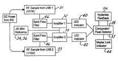
- An RF sample signal, 31 and 33is taken from each LNB.
- a simple microprocessoris capable of the measurement, storage, and calculations of the present invention.
- the signal 31 , 33is compared to a first reference signal 34 , 36 for the respective LNB.
- a comparator 35determines if the sample signal 31 meets a first predetermined threshold value 34 and a peak detector 37 detects the peak so that a peak indicator 40 can provide an indication that a peak signal has been detected for that particular LNB 20 .
- the other LNB 24sends a second sample signal 33 that is compared 35 to a second predetermined threshold value 36 until a peak is detected 37 and an indication 42 that a peak signal has been detected for the second LNB 24 is provided.
- the LNB signalsare compared to each other in the comparator 35 and to a maximum peak value to provide a master-lock indicator 44 to the installer.
- a band pass filter 46 , 48is used for each sample signal 31 , 33 to isolate the portion of the signal that is of interest in the comparison. Further, the filtered signals 31 , 33 are amplified by amplifiers 52 , 54 to enhance the comparison to the threshold signals 34 , 36 .
- the present inventioncan be either analog or digital.
- analog versionit may be desirable to apply hysteresis feedback 56 to the comparison of the analog sample signals 31 , 33 to the threshold values 34 , 36 .
- the hysteresis 56will prevent the indicator from toggling.
- the present inventioncould take the form of a handheld device 50 , as shown in FIG. 3 .
- This device 50is temporarily inserted in line with the LNB's 20 , 24 and the receiver 26 in order to perform the installation and then is removed.
- the handheld deviceincludes indicators 40 , 42 and 44 for providing peak detection indication to the user.
- the indicatorsmay be visual, such as an LED, or audible, such as a tone indicator.
- the devicetakes other forms and the peak indicators are audible and/or visual indicators as well.
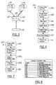
- FIG. 4shows a triple feed LNB 70 has integrated LED's 72 , 74 , and 76 representing first peak, second peak and master lock indicators respectively.
- FIG. 5there is shown a triple feed LNB 80 wherein first and second peak indicators 82 and 84 are bar graphs, or a plurality of LED's, that light up according to signal quality, and a master lock indicator 86 . It should be noted that these embodiments are described for example purposes and that one of ordinary skill in the art is capable of making structural changes without departing from the scope of the present invention.
- FIG. 6shows a flow chart of the method 100 of the present invention in analog form.
- the IRDis used as the power source in this open loop configuration.
- the LNB'sare powered 102 from the IRD in an alternating fashion.
- a sample signalis taken 104 from each LNB when it is powered.
- the sampled signalis filtered 106 to isolate the portion of the signal that is of interest.
- the signalis amplified 108 , and compared 110 to a threshold value to make a peak determination 112 for each LNB.
- the LNB peaksare compared to make a determination of a master lock.
- a master lock indicatoris provided 114 .
- hysteresis feedback 56is taken into account when the signal is near threshold to make the indicator more stable.
- FIG. 7shows a flow chart of the method 200 of the present invention in a digital form.
- the codesare used to indicate signal quality in the peak determination for a master lock.
- the LNB'sare powered 202 by the IRD consecutively.
- the LNBsends signal information 204 back to the IRD.
- the IRDassigns 206 a code, such as a DiSEqC code, PWM code, or tone, based on the signal information at the LNB.
- the codeis compared 208 to a threshold for each LNB, and then the thresholds are compared to each other for a master lock 210 .
- the DiSEqC codesare already in the IRD and therefore the method does not require the generation of new signals for signal strength measurements and peak indications. Further, digital processes are less sensitive than analog devices and therefore much less complex. For example, there is no need to take hysteresis into account in this digital method.
- FIG. 8is a table of DiSEqC codes that could be used in assigning codes to the sample signals taken at the LNB's.
- the DiSEqC code assignedcan be translated into the applicable condition. For example, code 248 indicates the alignment system is “OFF”. Code 255 would indicate a master signal lock.
- FIG. 9is a flowchart for a dynamic threshold value used to detect peak signals in the present invention.
- the dynamic threshold valueis advantageous because it reduces the time needed to setup and align a multi-satellite dish antenna.
- the antennais put in setup mode 302 for a first boresight angle, either azimuth or elevation, and slowly rotated left and right.
- the antennasearches 304 for the 101° W signal, records values 306 , and stores 308 a peak reading A. Once a peak value has been stored, it is possible to indicate 310 to the user or operator that the peak signal has been found.
- a blinking LEDmay be used to indicate the antenna is searching and a constantly lit LED may be used to indicate the peak has been found and stored. It is possible that one skilled in the art could use a different method to achieve the same result, which is to provide an indication that the signal is being searched and then provide an indication that the signal has been found.
- the search 312begins for the 119° W signal.
- the dishis rotated, values are stored 314 , and a peak reading B is stored 314 . Again, it is desirable to provide an indication 316 to the user that the signal is being searched for and then another indication should be provided when the peak signal has been found.
- a measurement 318is made of the current signal value for the 101° W signal, that is saved 320 as C.
- the dynamic thresholdis calculated 322 as follows:
- the dish antennaWhile monitoring 324 the 101° W signal, the dish antenna is moved 326 in the desired boresight until the signal is equal to the value calculated as F. The dish is secured 328 in the first boresight position. Once the value F has been detected, an indication 330 , i.e. an LED, should be provided to notify the user that the first alignment has been accomplished. The entire alignment procedure is then repeated 332 for the remaining boresight angle. For example, if azimuth adjustments were completed, the procedure is completed for elevation adjustments in the same manner as for the azimuth.
Landscapes
- Input Circuits Of Receivers And Coupling Of Receivers And Audio Equipment (AREA)
- Variable-Direction Aerials And Aerial Arrays (AREA)
Abstract
Description
Claims (18)
Priority Applications (1)
| Application Number | Priority Date | Filing Date | Title |
|---|---|---|---|
| US10/339,949US6693587B1 (en) | 2003-01-10 | 2003-01-10 | Antenna/feed alignment system for reception of multibeam DBS signals |
Applications Claiming Priority (1)
| Application Number | Priority Date | Filing Date | Title |
|---|---|---|---|
| US10/339,949US6693587B1 (en) | 2003-01-10 | 2003-01-10 | Antenna/feed alignment system for reception of multibeam DBS signals |
Publications (1)
| Publication Number | Publication Date |
|---|---|
| US6693587B1true US6693587B1 (en) | 2004-02-17 |
Family
ID=31188248
Family Applications (1)
| Application Number | Title | Priority Date | Filing Date |
|---|---|---|---|
| US10/339,949Expired - LifetimeUS6693587B1 (en) | 2003-01-10 | 2003-01-10 | Antenna/feed alignment system for reception of multibeam DBS signals |
Country Status (1)
| Country | Link |
|---|---|
| US (1) | US6693587B1 (en) |
Cited By (27)
| Publication number | Priority date | Publication date | Assignee | Title |
|---|---|---|---|---|
| US20040227655A1 (en)* | 2003-03-05 | 2004-11-18 | King Lael D. | Semi-automatic satellite locator system |
| US20050144649A1 (en)* | 2003-11-25 | 2005-06-30 | James Bertonis | Apparatus and method for reduction of wireless links noise injection to a DOCSIS cable modem service |
| EP1596465A1 (en)* | 2004-05-14 | 2005-11-16 | Thomson Licensing | Method for automatically detecting an antenna system for satellite receivers |
| US20050264700A1 (en)* | 2004-05-11 | 2005-12-01 | Funai Electric Co., Ltd. | Digital television broadcast signal receiver |
| US20060119509A1 (en)* | 2004-11-19 | 2006-06-08 | Wang James J | Method and apparatus for fast satellite acquisition via signal identification |
| EP1746683A1 (en)* | 2005-07-18 | 2007-01-24 | Advanced Digital Broadcast S.A. | Signal receiver and method for aligning antenna for reception of at least two signals |
| EP1723793A4 (en)* | 2004-03-09 | 2007-02-21 | Thomson Licensing | OPERATING CHECK OF 22 KHZ TONE IN A DECODER |
| US20070080860A1 (en)* | 2005-10-12 | 2007-04-12 | Norin John L | KA/KU antenna alignment |
| US20070082610A1 (en)* | 2005-10-12 | 2007-04-12 | Kesse Ho | Dynamic current sharing in Ka/Ku LNB design |
| US20070080861A1 (en)* | 2005-10-12 | 2007-04-12 | John Norin | Novel alignment method for multi-satellite consumer receiver antennas |
| US20070296469A1 (en)* | 2004-11-03 | 2007-12-27 | Fitzpatrick John J | Data Receiving Circuit With Current Mirror and Data Slicer |
| US20080186242A1 (en)* | 2007-02-07 | 2008-08-07 | Sam Shuster | Enclosed mobile/transportable satellite antenna system |
| US20080297406A1 (en)* | 2007-06-01 | 2008-12-04 | Microsoft Corporation | Automatic detection of communications satellite |
| US20090262033A1 (en)* | 2007-02-07 | 2009-10-22 | Lael King | Releasably mountable mobile/transportable motorized antenna system |
| EP2224627A2 (en) | 2009-02-27 | 2010-09-01 | Michael Rosenbusch | LNB having indication function |
| US20110012801A1 (en)* | 2009-07-20 | 2011-01-20 | Monte Thomas D | Multi-Feed Antenna System for Satellite Communicatons |
| US20110030015A1 (en)* | 2009-08-01 | 2011-02-03 | Lael King | Enclosed antenna system for receiving broadcasts from multiple sources |
| US20110059690A1 (en)* | 2004-05-28 | 2011-03-10 | Echostar Technologies L.L.C | Method and Device for Band Translation |
| US20110151769A1 (en)* | 2008-09-26 | 2011-06-23 | John James Fitzpatrick | Method for controlling signal transmission for multiple devices |
| US20120108192A1 (en)* | 2010-10-29 | 2012-05-03 | Wavenetix Corp. | Signal detection assisted by use of moving antennae |
| US20130321206A1 (en)* | 2012-05-29 | 2013-12-05 | Chang Donald C D | Interference rejections of satellite ground terminal with orthogonal beams |
| US8789116B2 (en) | 2011-11-18 | 2014-07-22 | Electronic Controlled Systems, Inc. | Satellite television antenna system |
| US9179170B2 (en) | 2005-05-27 | 2015-11-03 | EchoStar Technologies, L.L.C. | Low noise block converter feedhorn |
| US9451220B1 (en)* | 2014-12-30 | 2016-09-20 | The Directv Group, Inc. | System and method for aligning a multi-satellite receiver antenna |
| US9503177B1 (en) | 2014-12-30 | 2016-11-22 | The Directv Group, Inc. | Methods and systems for aligning a satellite receiver dish using a smartphone or tablet device |
| US9521378B1 (en) | 2014-12-30 | 2016-12-13 | The Directv Group, Inc. | Remote display of satellite receiver information |
| WO2021247019A1 (en)* | 2020-06-03 | 2021-12-09 | Arris Enterprises Llc. | System and method for automated determination of satellite transceiver type |
Citations (8)
| Publication number | Priority date | Publication date | Assignee | Title |
|---|---|---|---|---|
| US5579367A (en) | 1995-03-13 | 1996-11-26 | Chaparral Communications, Inc. | Multi-medium closed-loop controlled satellite broadcast network for simple end-user operation |
| US5983071A (en) | 1997-07-22 | 1999-11-09 | Hughes Electronics Corporation | Video receiver with automatic satellite antenna orientation |
| US6029044A (en) | 1997-02-03 | 2000-02-22 | Hughes Electronics Corporation | Method and apparatus for in-line detection of satellite signal lock |
| US6216266B1 (en) | 1999-10-28 | 2001-04-10 | Hughes Electronics Corporation | Remote control signal level meter |
| US6344832B1 (en)* | 1998-04-20 | 2002-02-05 | Organisation Europenne De Telecommunications Par Satellite Eutelsat | Frequency converter arrangement for parabolic antennae |
| US6441797B1 (en)* | 2000-09-29 | 2002-08-27 | Hughes Electronics Corporation | Aggregated distribution of multiple satellite transponder signals from a satellite dish antenna |
| US6600730B1 (en)* | 1998-08-20 | 2003-07-29 | Hughes Electronics Corporation | System for distribution of satellite signals from separate multiple satellites on a single cable line |
| US20030163822A1 (en)* | 2002-02-26 | 2003-08-28 | Knutson Paul Gothard | Satellite television system ground station having wideband multi-channel LNB converter/transmitter architecture with coarse tuner in outdoor unit |
- 2003
- 2003-01-10USUS10/339,949patent/US6693587B1/ennot_activeExpired - Lifetime
Patent Citations (8)
| Publication number | Priority date | Publication date | Assignee | Title |
|---|---|---|---|---|
| US5579367A (en) | 1995-03-13 | 1996-11-26 | Chaparral Communications, Inc. | Multi-medium closed-loop controlled satellite broadcast network for simple end-user operation |
| US6029044A (en) | 1997-02-03 | 2000-02-22 | Hughes Electronics Corporation | Method and apparatus for in-line detection of satellite signal lock |
| US5983071A (en) | 1997-07-22 | 1999-11-09 | Hughes Electronics Corporation | Video receiver with automatic satellite antenna orientation |
| US6344832B1 (en)* | 1998-04-20 | 2002-02-05 | Organisation Europenne De Telecommunications Par Satellite Eutelsat | Frequency converter arrangement for parabolic antennae |
| US6600730B1 (en)* | 1998-08-20 | 2003-07-29 | Hughes Electronics Corporation | System for distribution of satellite signals from separate multiple satellites on a single cable line |
| US6216266B1 (en) | 1999-10-28 | 2001-04-10 | Hughes Electronics Corporation | Remote control signal level meter |
| US6441797B1 (en)* | 2000-09-29 | 2002-08-27 | Hughes Electronics Corporation | Aggregated distribution of multiple satellite transponder signals from a satellite dish antenna |
| US20030163822A1 (en)* | 2002-02-26 | 2003-08-28 | Knutson Paul Gothard | Satellite television system ground station having wideband multi-channel LNB converter/transmitter architecture with coarse tuner in outdoor unit |
Cited By (62)
| Publication number | Priority date | Publication date | Assignee | Title |
|---|---|---|---|---|
| US20040227655A1 (en)* | 2003-03-05 | 2004-11-18 | King Lael D. | Semi-automatic satellite locator system |
| US20080136722A1 (en)* | 2003-03-05 | 2008-06-12 | King Lael D | Semi-automatic satellite locator system |
| US6937199B2 (en) | 2003-03-05 | 2005-08-30 | Electronic Controlled Systems, Inc. | Semi-automatic satellite locator system |
| US7301505B2 (en) | 2003-03-05 | 2007-11-27 | King Controls | Semi-automatic satellite locator system |
| US7570222B2 (en) | 2003-03-05 | 2009-08-04 | King Controls | Semi-automatic satellite locator system |
| US20060170603A1 (en)* | 2003-03-05 | 2006-08-03 | King Lael D | Semi-automatic satellite locator system |
| US20050144649A1 (en)* | 2003-11-25 | 2005-06-30 | James Bertonis | Apparatus and method for reduction of wireless links noise injection to a DOCSIS cable modem service |
| EP1723793A4 (en)* | 2004-03-09 | 2007-02-21 | Thomson Licensing | OPERATING CHECK OF 22 KHZ TONE IN A DECODER |
| US7685621B2 (en)* | 2004-05-11 | 2010-03-23 | Funai Electric Co., Ltd. | Digital television broadcast signal receiver |
| US20050264700A1 (en)* | 2004-05-11 | 2005-12-01 | Funai Electric Co., Ltd. | Digital television broadcast signal receiver |
| FR2870393A1 (en)* | 2004-05-14 | 2005-11-18 | Thomson Licensing Sa | METHOD FOR SELF-DETECTING ANTENNA SYSTEM FOR SATELLITE RECEIVER |
| US7890981B2 (en) | 2004-05-14 | 2011-02-15 | Thomson Licensing | Method for automatically detecting an antenna system for satellite receivers |
| EP1596465A1 (en)* | 2004-05-14 | 2005-11-16 | Thomson Licensing | Method for automatically detecting an antenna system for satellite receivers |
| US8855547B2 (en) | 2004-05-28 | 2014-10-07 | Echostar Technologies L.L.C. | Method and device for band translation |
| US20110059690A1 (en)* | 2004-05-28 | 2011-03-10 | Echostar Technologies L.L.C | Method and Device for Band Translation |
| US8369772B2 (en)* | 2004-05-28 | 2013-02-05 | Echostar Technologies L.L.C. | Method and device for band translation |
| US20070296469A1 (en)* | 2004-11-03 | 2007-12-27 | Fitzpatrick John J | Data Receiving Circuit With Current Mirror and Data Slicer |
| US8433239B2 (en) | 2004-11-03 | 2013-04-30 | Thomson Licensing | Data receiving circuit with current mirror and data slicer |
| US7262732B2 (en)* | 2004-11-19 | 2007-08-28 | Motia Inc. | Method and apparatus for fast satellite acquisition via signal identification |
| US20060119509A1 (en)* | 2004-11-19 | 2006-06-08 | Wang James J | Method and apparatus for fast satellite acquisition via signal identification |
| US9179170B2 (en) | 2005-05-27 | 2015-11-03 | EchoStar Technologies, L.L.C. | Low noise block converter feedhorn |
| EP1746683A1 (en)* | 2005-07-18 | 2007-01-24 | Advanced Digital Broadcast S.A. | Signal receiver and method for aligning antenna for reception of at least two signals |
| US8515342B2 (en)* | 2005-10-12 | 2013-08-20 | The Directv Group, Inc. | Dynamic current sharing in KA/KU LNB design |
| US20070080860A1 (en)* | 2005-10-12 | 2007-04-12 | Norin John L | KA/KU antenna alignment |
| US7663543B2 (en)* | 2005-10-12 | 2010-02-16 | The Directv Group, Inc. | Alignment method for multi-satellite consumer receiver antennas |
| US20070080861A1 (en)* | 2005-10-12 | 2007-04-12 | John Norin | Novel alignment method for multi-satellite consumer receiver antennas |
| US20070082610A1 (en)* | 2005-10-12 | 2007-04-12 | Kesse Ho | Dynamic current sharing in Ka/Ku LNB design |
| US20100085256A1 (en)* | 2005-10-12 | 2010-04-08 | The Directv Group, Inc. | Ka/ku antenna alignment |
| US20100141526A1 (en)* | 2005-10-12 | 2010-06-10 | The Directv Group, Inc. | Novel alignment method for multi-satellite consumer receiver antennas |
| US8106842B2 (en) | 2005-10-12 | 2012-01-31 | The Directv Group, Inc. | Ka/Ku antenna alignment |
| US7636067B2 (en) | 2005-10-12 | 2009-12-22 | The Directv Group, Inc. | Ka/Ku antenna alignment |
| US7855680B2 (en) | 2005-10-12 | 2010-12-21 | The Directv Group, Inc. | Alignment method for multi-satellite consumer receiver antennas |
| US20090262033A1 (en)* | 2007-02-07 | 2009-10-22 | Lael King | Releasably mountable mobile/transportable motorized antenna system |
| US8816923B2 (en) | 2007-02-07 | 2014-08-26 | Electronic Controlled Systems, Inc. | Motorized satellite television antenna system |
| US7595764B2 (en) | 2007-02-07 | 2009-09-29 | Wallace Technologies | Enclosed mobile/transportable satellite antenna system |
| US7679573B2 (en) | 2007-02-07 | 2010-03-16 | King Controls | Enclosed mobile/transportable motorized antenna system |
| US20080186242A1 (en)* | 2007-02-07 | 2008-08-07 | Sam Shuster | Enclosed mobile/transportable satellite antenna system |
| US20080246677A1 (en)* | 2007-02-07 | 2008-10-09 | Sam Shuster | Enclosed mobile/transportable satellite antenna system |
| US8934833B2 (en)* | 2007-06-01 | 2015-01-13 | Microsoft Corporation | Automatic detection of communications satellite |
| US20080297406A1 (en)* | 2007-06-01 | 2008-12-04 | Microsoft Corporation | Automatic detection of communications satellite |
| US8903306B2 (en)* | 2008-09-26 | 2014-12-02 | Thomson Licensing | Method for controlling signal transmission for multiple devices |
| US20110151769A1 (en)* | 2008-09-26 | 2011-06-23 | John James Fitzpatrick | Method for controlling signal transmission for multiple devices |
| US8260237B2 (en)* | 2009-02-27 | 2012-09-04 | Michael Rosenbusch | LNB having indication function |
| EP2224627A3 (en)* | 2009-02-27 | 2012-10-03 | Michael Rosenbusch | LNB having indication function |
| US20100222018A1 (en)* | 2009-02-27 | 2010-09-02 | Michael Rosenbusch | Lnb having indication function |
| EP2224627A2 (en) | 2009-02-27 | 2010-09-01 | Michael Rosenbusch | LNB having indication function |
| US20110012801A1 (en)* | 2009-07-20 | 2011-01-20 | Monte Thomas D | Multi-Feed Antenna System for Satellite Communicatons |
| US8334815B2 (en) | 2009-07-20 | 2012-12-18 | Kvh Industries, Inc. | Multi-feed antenna system for satellite communications |
| US20110030015A1 (en)* | 2009-08-01 | 2011-02-03 | Lael King | Enclosed antenna system for receiving broadcasts from multiple sources |
| US8368611B2 (en) | 2009-08-01 | 2013-02-05 | Electronic Controlled Systems, Inc. | Enclosed antenna system for receiving broadcasts from multiple sources |
| US20120108192A1 (en)* | 2010-10-29 | 2012-05-03 | Wavenetix Corp. | Signal detection assisted by use of moving antennae |
| US8565687B2 (en)* | 2010-10-29 | 2013-10-22 | Wavenetix Corp. | Signal detection assisted by use of moving antennae |
| US9118974B2 (en) | 2011-11-18 | 2015-08-25 | Electronic Controlled Systems, Inc. | Satellite television antenna system |
| US8789116B2 (en) | 2011-11-18 | 2014-07-22 | Electronic Controlled Systems, Inc. | Satellite television antenna system |
| US20130321206A1 (en)* | 2012-05-29 | 2013-12-05 | Chang Donald C D | Interference rejections of satellite ground terminal with orthogonal beams |
| US9451220B1 (en)* | 2014-12-30 | 2016-09-20 | The Directv Group, Inc. | System and method for aligning a multi-satellite receiver antenna |
| US9503177B1 (en) | 2014-12-30 | 2016-11-22 | The Directv Group, Inc. | Methods and systems for aligning a satellite receiver dish using a smartphone or tablet device |
| US9521378B1 (en) | 2014-12-30 | 2016-12-13 | The Directv Group, Inc. | Remote display of satellite receiver information |
| US9888217B2 (en) | 2014-12-30 | 2018-02-06 | The Directv Group, Inc | Remote display of satellite receiver information |
| US10805580B2 (en) | 2014-12-30 | 2020-10-13 | The Directv Group, Inc. | Remote display of satellite receiver information |
| WO2021247019A1 (en)* | 2020-06-03 | 2021-12-09 | Arris Enterprises Llc. | System and method for automated determination of satellite transceiver type |
| US11936464B2 (en) | 2020-06-03 | 2024-03-19 | Arris Enterprises Llc | System and method for automated determination of satellite transceiver type |
Similar Documents
| Publication | Publication Date | Title |
|---|---|---|
| US6693587B1 (en) | Antenna/feed alignment system for reception of multibeam DBS signals | |
| US7016643B1 (en) | Antenna positioning system and method for simultaneous reception of signals from a plurality of satellites | |
| US5903237A (en) | Antenna pointing aid | |
| US7289062B2 (en) | Method and device for accurately pointing a satellite earth station antenna | |
| US6029044A (en) | Method and apparatus for in-line detection of satellite signal lock | |
| KR100425643B1 (en) | Satellite receiver and method for receiving at a satellite receiver a broadcast signal transmitting digital video and audio data | |
| US7773937B2 (en) | Method and apparatus for in-line detection of satellite signal lock | |
| EP0725456B1 (en) | Apparatus for positioning an antenna in a remote ground terminal | |
| EP1608083B1 (en) | Diversity with identification of specific antenna properties and evaluation thereof | |
| US11394474B2 (en) | Satellite tracking antenna system in a plurality of satellite environments and satellite tracking method using the same | |
| US4990924A (en) | Satellite locating system | |
| US20100151799A1 (en) | Transceiver using millimeter-wave | |
| EP1332532B1 (en) | Automatic antennae system | |
| US5488379A (en) | Apparatus and method for positioning an antenna in a remote ground terminal | |
| WO2012067779A1 (en) | Wall plate digital television antenna signal meter and method | |
| US7359448B2 (en) | Remote transmitter system and method | |
| US20090219207A1 (en) | Signal receiving system | |
| US8446984B2 (en) | Method and system for identification of portable antenna modules | |
| US7733252B2 (en) | Method and apparatus for delay and combining circuitry | |
| JP2005160078A (en) | Receiving system including pointing auxiliary device | |
| EP1580833A1 (en) | Device and method for positioning of a dish antenna | |
| KR20210097403A (en) | Automatic satellite tracking antenna system and satellite selection method using the same | |
| US20060052078A1 (en) | Device for amplifying the signal from a receive antenna | |
| KR20020041770A (en) | Auto-direction selector for antenna | |
| JP2007074427A (en) | Optical receiver, and squelch operation method of optical receiver |
Legal Events
| Date | Code | Title | Description |
|---|---|---|---|
| AS | Assignment | Owner name:HUGHES ELECTRONICS CORPORATION, CALIFORNIA Free format text:ASSIGNMENT OF ASSIGNORS INTEREST;ASSIGNORS:KUETHER, DAVID J.;HO, KESSE;REEL/FRAME:013673/0128 Effective date:20021202 | |
| STCF | Information on status: patent grant | Free format text:PATENTED CASE | |
| FPAY | Fee payment | Year of fee payment:4 | |
| FPAY | Fee payment | Year of fee payment:8 | |
| FPAY | Fee payment | Year of fee payment:12 | |
| AS | Assignment | Owner name:THE DIRECTV GROUP, INC., CALIFORNIA Free format text:MERGER AND CHANGE OF NAME;ASSIGNORS:HUGHES ELECTRONICS CORPORATION;THE DIRECTV GROUP, INC.;REEL/FRAME:056981/0728 Effective date:20040316 | |
| AS | Assignment | Owner name:DIRECTV, LLC, CALIFORNIA Free format text:ASSIGNMENT OF ASSIGNORS INTEREST;ASSIGNOR:THE DIRECTV GROUP, INC.;REEL/FRAME:057033/0451 Effective date:20210728 | |
| AS | Assignment | Owner name:CREDIT SUISSE AG, CAYMAN ISLANDS BRANCH, AS COLLATERAL AGENT, NEW YORK Free format text:SECURITY AGREEMENT;ASSIGNOR:DIRECTV, LLC;REEL/FRAME:057695/0084 Effective date:20210802 | |
| AS | Assignment | Owner name:THE BANK OF NEW YORK MELLON TRUST COMPANY, N.A. AS COLLATERAL AGENT, TEXAS Free format text:SECURITY AGREEMENT;ASSIGNOR:DIRECTV, LLC;REEL/FRAME:058220/0531 Effective date:20210802 | |
| AS | Assignment | Owner name:THE BANK OF NEW YORK MELLON TRUST COMPANY, N.A., AS COLLATERAL AGENT, TEXAS Free format text:SECURITY AGREEMENT;ASSIGNOR:DIRECTV, LLC;REEL/FRAME:066371/0690 Effective date:20240124 |