US6693511B1 - System and method for communicating with dormant radio frequency identification tags - Google Patents
System and method for communicating with dormant radio frequency identification tagsDownload PDFInfo
- Publication number
- US6693511B1 US6693511B1US09/405,364US40536499AUS6693511B1US 6693511 B1US6693511 B1US 6693511B1US 40536499 AUS40536499 AUS 40536499AUS 6693511 B1US6693511 B1US 6693511B1
- Authority
- US
- United States
- Prior art keywords
- transponder
- sensor
- signal
- state
- radio frequency
- Prior art date
- Legal status (The legal status is an assumption and is not a legal conclusion. Google has not performed a legal analysis and makes no representation as to the accuracy of the status listed.)
- Expired - Lifetime
Links
- 238000000034methodMethods0.000titleclaimsabstractdescription60
- 230000006854communicationEffects0.000claimsdescription28
- 238000004891communicationMethods0.000claimsdescription28
- 230000033001locomotionEffects0.000claimsdescription25
- 238000012545processingMethods0.000claimsdescription14
- 230000005540biological transmissionEffects0.000claimsdescription12
- 238000001228spectrumMethods0.000claimsdescription3
- 230000003595spectral effectEffects0.000claims1
- 239000000523sampleSubstances0.000abstractdescription3
- 238000005259measurementMethods0.000abstract1
- 238000003491arrayMethods0.000description43
- 238000010586diagramMethods0.000description14
- 230000006870functionEffects0.000description13
- 239000013598vectorSubstances0.000description11
- 230000008569processEffects0.000description9
- 230000000694effectsEffects0.000description7
- 238000010168coupling processMethods0.000description6
- 230000000875corresponding effectEffects0.000description5
- 230000008878couplingEffects0.000description5
- 238000005859coupling reactionMethods0.000description5
- 230000010363phase shiftEffects0.000description5
- 230000004888barrier functionEffects0.000description4
- 239000000463materialSubstances0.000description4
- 230000004044responseEffects0.000description4
- 230000035945sensitivityEffects0.000description4
- 239000007787solidSubstances0.000description4
- 230000002238attenuated effectEffects0.000description3
- 235000012489doughnutsNutrition0.000description3
- 238000005516engineering processMethods0.000description3
- 238000009434installationMethods0.000description3
- 238000012423maintenanceMethods0.000description3
- 238000013459approachMethods0.000description2
- 230000000712assemblyEffects0.000description2
- 238000000429assemblyMethods0.000description2
- 230000008901benefitEffects0.000description2
- 125000004122cyclic groupChemical group0.000description2
- 230000008030eliminationEffects0.000description2
- 238000003379elimination reactionMethods0.000description2
- 239000011888foilSubstances0.000description2
- 230000000977initiatory effectEffects0.000description2
- 229910052751metalInorganic materials0.000description2
- 239000002184metalSubstances0.000description2
- 230000010287polarizationEffects0.000description2
- RYGMFSIKBFXOCR-UHFFFAOYSA-NCopperChemical compound[Cu]RYGMFSIKBFXOCR-UHFFFAOYSA-N0.000description1
- 229910052782aluminiumInorganic materials0.000description1
- XAGFODPZIPBFFR-UHFFFAOYSA-NaluminiumChemical compound[Al]XAGFODPZIPBFFR-UHFFFAOYSA-N0.000description1
- 230000003321amplificationEffects0.000description1
- 238000004458analytical methodMethods0.000description1
- 230000007175bidirectional communicationEffects0.000description1
- 239000003990capacitorSubstances0.000description1
- 239000000969carrierSubstances0.000description1
- 230000001427coherent effectEffects0.000description1
- 239000004020conductorSubstances0.000description1
- 238000010276constructionMethods0.000description1
- 230000002596correlated effectEffects0.000description1
- 230000001419dependent effectEffects0.000description1
- 230000005684electric fieldEffects0.000description1
- 230000005670electromagnetic radiationEffects0.000description1
- 230000004907fluxEffects0.000description1
- 239000004519greaseSubstances0.000description1
- RGNPBRKPHBKNKX-UHFFFAOYSA-NhexaflumuronChemical compoundC1=C(Cl)C(OC(F)(F)C(F)F)=C(Cl)C=C1NC(=O)NC(=O)C1=C(F)C=CC=C1FRGNPBRKPHBKNKX-UHFFFAOYSA-N0.000description1
- 238000003199nucleic acid amplification methodMethods0.000description1
- 230000003287optical effectEffects0.000description1
- 230000035699permeabilityEffects0.000description1
- 230000000644propagated effectEffects0.000description1
- 238000011084recoveryMethods0.000description1
- 238000006467substitution reactionMethods0.000description1
- 230000002123temporal effectEffects0.000description1
- 239000010409thin filmSubstances0.000description1
- 238000012546transferMethods0.000description1
- 230000002618waking effectEffects0.000description1
- 229910000859α-FeInorganic materials0.000description1
Images


Classifications
- G—PHYSICS
- G01—MEASURING; TESTING
- G01S—RADIO DIRECTION-FINDING; RADIO NAVIGATION; DETERMINING DISTANCE OR VELOCITY BY USE OF RADIO WAVES; LOCATING OR PRESENCE-DETECTING BY USE OF THE REFLECTION OR RERADIATION OF RADIO WAVES; ANALOGOUS ARRANGEMENTS USING OTHER WAVES
- G01S5/00—Position-fixing by co-ordinating two or more direction or position line determinations; Position-fixing by co-ordinating two or more distance determinations
- G01S5/02—Position-fixing by co-ordinating two or more direction or position line determinations; Position-fixing by co-ordinating two or more distance determinations using radio waves
- G01S5/10—Position of receiver fixed by co-ordinating a plurality of position lines defined by path-difference measurements, e.g. omega or decca systems
- G—PHYSICS
- G01—MEASURING; TESTING
- G01S—RADIO DIRECTION-FINDING; RADIO NAVIGATION; DETERMINING DISTANCE OR VELOCITY BY USE OF RADIO WAVES; LOCATING OR PRESENCE-DETECTING BY USE OF THE REFLECTION OR RERADIATION OF RADIO WAVES; ANALOGOUS ARRANGEMENTS USING OTHER WAVES
- G01S13/00—Systems using the reflection or reradiation of radio waves, e.g. radar systems; Analogous systems using reflection or reradiation of waves whose nature or wavelength is irrelevant or unspecified
- G01S13/74—Systems using reradiation of radio waves, e.g. secondary radar systems; Analogous systems
- G01S13/75—Systems using reradiation of radio waves, e.g. secondary radar systems; Analogous systems using transponders powered from received waves, e.g. using passive transponders, or using passive reflectors
- G01S13/751—Systems using reradiation of radio waves, e.g. secondary radar systems; Analogous systems using transponders powered from received waves, e.g. using passive transponders, or using passive reflectors wherein the responder or reflector radiates a coded signal
Definitions
- the present inventionrelates to radio frequency communication, and specifically to the use of radio frequency identification (RFID) tags in conjunction with one or more radio frequency sensors to determine the position of the tag or an asset to which the tag is attached within three dimensional space.
- RFIDradio frequency identification
- the field of RFIDRadio Frequency Identification
- Applications of RFID technologyare wide ranging and include counting objects as they pass near to a sensor, uniquely identifying a specific tag (hereinafter “transponder”) and associated asset, and placing data within the RFID transponder for later recovery.
- the process of “reading” and communicating with an RFID transpondergenerally comprises bringing the transponder in proximity to an RFID sensor which emanates a radio frequency wake-up field having a limited range.
- the RFID transponderdetects the presence of the wakeup field of the sensor, and subsequently various forms or protocols of handshake occur between the transponder and the sensor in order to exchange data. All of this communication between the transponder and the sensor is performed using radio frequency carriers of some kind.
- anti-clash protocolsof the type well understood in the data processing arts are employed in order to multiplex or provide multiple access to the sensor by the multiple transponders.
- the main advantages of an RFID sensor and transponder system over other forms of ID tagginginclude (i) the orientation of the transponder with respect to the sensor is not critical for a correct read of the transponder information; (ii) communication can occur within comparatively harsh operating environments including dirt, grease, opaque gasses, etc.; and (iii) the communication range between the sensor and transponder can be significant (in excess of 100 feet in certain cases) even when the RF frequencies used are within the power limitations of Federal Communications Commission (FCC) rules concerning unlicensed transmitters. Accordingly, RFID technology is useful for several applications, especially those relating to security and asset management.
- FCCFederal Communications Commission
- RFID systems using electromagnetic energy with very low frequencyare attractive since the low frequency energy tends to suffer low losses from shielding materials such as metal boxes, aluminum foil, and the like.
- shielding materialssuch as metal boxes, aluminum foil, and the like.
- Those who would surreptitiously remove the tagged assets from a buildingusually try to use such shielding techniques.
- these low frequenciestypically require large antennas within the transponder in order to achieve reasonable levels of RF coupling between the sensor and the transponder. It is impractical to place large wire antennas within small transponders; accordingly, comparatively small magnetic loop antennas are the coupling methods of choice for such small transponders.
- the magnetic loop antenna of the transpondercan only receive energy from the sensor antenna coils only when the orientation of the sensor and transponder coils is similar.
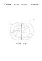
- the “rejection” solid angle for a loop antennacan be thought of as a band of a certain solid angle measured from the center and oriented 360 degrees around the circumference of the loop (see FIG. 1 ).
- the transpondermay be well within the sensor's intended wake up field, but fails to detect the sensor's emissions, and therefore also fails to communicate therewith.
- a related problemis when the position and/or orientation of the transponder within the field is varied, thereby taking the sensor(s) out of the “figure-8” pattern of the transponder antenna, and interrupting communication between the transponder and sensor.
- RFID transponder/sensor systemsdo not have the ability to locate the transponder in spatial space. Those which do have this ability suffer from significant drawbacks since none of them will function using the low frequency signals needed to pass through foil and other shielding.
- the added capability of spatial positioningallows the sensor to gather more information about the transponder, i.e., its relative location in space with respect to the sensor or some other reference point. This capability provides a very significant advantage over other asset management systems (RFID or otherwise) which can not determine the position of the assets.
- transponderincludes a motion sensor or other device which activates or otherwise permits the waking up of the transponder
- system sensorreader
- transpondermust be physically moved or agitated during these periods in order to enable the transponder to communicate with the sensor. This approach is cumbersome and inefficient.
- an improved apparatus and method for spatially locating an RFID transponder having a magnetic loop antenna within one or more sensor fieldsis needed. Furthermore, an improved apparatus and method for maintaining effectively constant and uninterrupted communication with the aforementioned RFID transponder regardless of physical position or orientation is needed. Lastly, an improved apparatus for interrogating and communicating with the RFID transponder when the transponder is not in motion or otherwise dormant is needed.
- an improved system for and method of determining the position of one or more radio frequency identification (RFID) transponders with respect to one or more sensorscomprises a plurality of stationary sensor arrays located within certain physical areas. Each sensor array comprises a plurality of antenna coils arranged in unique physical orientations with respect to each other and capable of transmitting radio frequency signals of differing phase.
- the RFID transponderincludes a magnetic loop antenna which receives the plurality of signals generated by the antenna coils, and compares the phase of at least two of the received signals in order to determine the relative position of the transponder(s) with respect to the sensors.
- an improved system for and method of maintaining constant communication between one or more RFID transponders and their associated sensor(s) using a multi-message protocolcomprises sensor arrays having a plurality of antenna coils in a predetermined physical relationship which emit two direction finding mode (DFM) signals in succession.
- DFMdirection finding mode
- each of the plurality of antenna coilsis energized so as to emit a signal in its given orientation.
- one of the plurality of coilsis turned off such that no radio frequency signal is emitted from that coil.
- the spatial relationship of the transponder and individual antenna coilsprecludes all of the signals from each sensor array from being rejected by the transponder during the emission of both the first and second DFM signals. In this fashion, the transponder coil can be kept in constant communication with the sensor, regardless of its orientation with respect to the sensors. This feature effectively eliminates the communication problems associated with the typical “figure-8” pattern associated with the transponder's antenna coil.
- an improved method of determining the location of the transponder with respect to two or more sensor arrays through elimination of sensor rejectioncomprises positioning the transponder with an internal antenna coil within the field generated by the coils of the individual sensor arrays, transmitting a first signal from each of the antenna coils of the two or more arrays, transmitting a second signal from a subset of the antenna coils of the same arrays (i.e., with one or more coils turned off), and determining the position of the transponder relative to the two or more sensor arrays based on the intensity of the first and second signals received by the antenna coil of the transponder.
- a system for and method of transmitting data between a sensor having a transmit coil and a RFID transponder having a receiving coilcomprises a hand-held sensor probe or wand which emits a highly intense and localized wake-up field at a predetermined frequency. This field is sensed by the receiving coil of the transponder, and its physical parameters (such as intensity and/or frequency) compared to predetermined values present within the transponder. If the sensed parameters of the wake-up field meet certain predetermined criteria, the transponder generates an internal wake-up signal, and begins communicating with the sensor.
- This system and methodare particularly useful when using transponders having an internal motion detector, thereby allowing communication with the dormant (e.g., motionless) transponder without the need to physically move the transponder.
- FIG. 1is an illustration of the magnetic field sensitivity pattern of a typical prior art loop antenna having a circular shape, based on 10 db downpoints of field strength.
- FIG. 2is diagrammatic representation of the three carrier wave phase vectors associated with the present invention.
- FIG. 3is a plot illustrating the positional angle measured by the transponder of the present invention as a function of the intensity of the signals received by the transponder from two three phase sensor arrays.
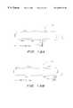
- FIG. 4is a plan view of an exemplary arrangement of the three phase sensor array of the present invention, placed with respect to a door.
- FIG. 5is a logical block diagram showing a portion of the communications between an RFID sensor and transponder of the present invention.
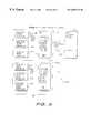
- FIG. 6is a block diagram of one embodiment of a stand-alone PC-based asset management system with network link according to the present invention.
- FIG. 7is a block diagram of one embodiment of a security system with network link according to the present invention.
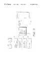
- FIG. 8is a block diagram of one embodiment of the sensor hardware and arrays shown in FIGS. 4, 5 , and 6 .
- FIG. 9is a block diagram of one embodiment of the sensors used in the sensor arrays of FIG. 8 .
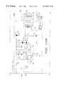
- FIG. 10is a schematic diagram of the three phase transmitter and antenna array portions of the sensor shown in FIG. 9 .
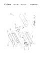
- FIG. 11is a physical assembly diagram showing one embodiment of the antenna coil configuration of the sensor arrays shown in FIGS. 8 and 9.
- FIGS. 12A and 12Bare diagrams of one embodiment of the end coils (left end and right end, respectively) for the Z-direction of the antenna coil configuration shown in FIG. 11 .
- FIG. 13Ais a diagram of one embodiment of the X-direction coil of the antenna coil configuration shown in FIG. 11 .
- FIG. 13Bis a diagram of one embodiment of the Y-direction coil of the antenna coil configuration shown in FIG. 11 .
- FIG. 14is a block diagram of one embodiment of the hardware configuration for the RFID transponder shown in FIG. 5 .
- FIG. 15is a plan view of the sensor array portion of the asset management and security system of the present invention in an exemplary installation, illustrating characteristic patterns of the transponder wake up range and sensor read range.
- FIG. 16is a logical state chart for the internal states of one embodiment of the transponder of FIG. 14 .
- FIG. 17is a schematic diagram of a portion of one embodiment of the transponder wake up circuit of the transponder of FIG. 14 .
- FIG. 18is a logical flow chart illustrating one embodiment of the two message direction finding mode (DFM) process performed by the asset management system of the present invention.
- DFMmessage direction finding mode
- FIG. 19is a logical flow chart of one embodiment of the position location technique utilized by the asset management system of the present invention.
- FIG. 20is a block diagram of one embodiment of the portable wake up sensor probe and system according to the present invention.
- tagsand “transponder” are used interchangeably, and are meant to include any mobile or semi-mobile radio-frequency device capable of transmitting, receiving, or both transmitting and receiving radio frequency energy in one or more frequency bands.
- sensorsand “reader” are used interchangeably, and are meant to include any fixed or semi-mobile radio frequency devices capable of receiving, transmitting, or both receiving and transmitting radio frequency energy in one or more frequency bands.
- the present inventionbroadly comprises a system by which an RFID transponder may communicate with an array of RF sensors, the signals emitted by the sensors aiding the transponder in locating its position relative to the sensors.
- the present inventionutilizes sensors (antenna coils) which emit three carrier waves each separated by a phase angle ⁇ , the phase angle in the present embodiment being equal to 120 degrees. In another embodiment, other phase angles are envisioned.
- the three carrier wavesare described by vectors where the magnitude of the magnetic field intensity H is described by:
- ⁇0, 120, and 240 degrees (0 ⁇ , 2/3 ⁇ , and 4/3 ⁇ radians), respectively, and
- ⁇angular frequency (radians/sec).
- Each of the three phase-shifted carrier signalsis transmitted by a corresponding loop antenna coil (see discussion of FIGS. 11-13 below), each antenna coil having its own “figure-8” pattern.
- Each of the three antenna coilsis arranged on one of three axes of a Cartesian (i.e., X, Y, Z) coordinate system.
- Cartesiani.e., X, Y, Z
- the magnetic field intensity around the coilsvaries both as a function of position and time.
- the foregoing antenna coil and three phase carrier arrangementcan be used to both transmit data to the transponder, and also provide information to the transponder regarding its position relative to the coils.
- the system of the present inventionutilizes the relative strength or intensity of the electromagnetic three phase signals radiated by two (or more) sensor arrays, herein designated as “A” and “B”, in order to provide position information to the transponder.
- the positional angle(relative to the antenna coils) is shown to be a function of the relative signals strengths present from the A and B arrays.
- the ratio of the signal strengthsis defined as:
- Ratio AB20*log 10 ( I A /I B ) Equation 2
- I AIntensity of received signal from “A” sensor array
- I BIntensity of received signal from “B” sensor array.
- the tagmay compute its positional angle relative to the known position of the arrays.
- the antenna arrays of the exemplary embodimentare arranged in pairs 404 , 406 , 408 , where one antenna coil assembly 402 of each pair is defined as being in one location relative to a door 410 (i.e., “inside” a building or an area in the present illustration, designated by the letter “A) and the other coil assembly of each pair is defined as being in a second location relative to the door 410 (i.e., “outside” of the building or an area, designated by the letter “B”).
- the coil spatial and phase orientationis shown for an “N” pair system.
- each of the coil assembliescontains three antenna phase coils having a differing electrical phase as previously described.
- the physical orientation of the coilsmay be as defined in FIG. 1 . It will be appreciated that the illustrated system of sensor arrays may be set up over an infinitely long barrier if desired, or configured in other arrangements.
- the systemis comprised generally of a radio frequency reader or sensor system 510 and a corresponding transponder 520 which are each in communication with one another.
- the transponder 520is dormant or in an inactive state when outside the field generated by the sensor(s) 510 . This dormant state reduces the power consumption of the transponder, since its internal processor 1406 (FIG. 14) and other components are inactive.
- the sensor system 510generates an electromagnetic “wake up” field 130 using an alternating current (AC) signal as is well known in the art; see the discussion of FIG.
- ACalternating current
- This wake up fieldis generated by the sensor system 510 in order to toggle the transponder 520 into the active state when the transponder 520 enters the wake up field (i.e., when the field detected by the internal magnetic loop antenna 1402 of the transponder as illustrated in FIG. 14 is of sufficient intensity), and the transponder is in motion.
- the sensor system 510communicates with the transponder 520 using an 8.13 kHz phase modulated signal, although it will be appreciated that other frequencies and/or modulation schemes may be used.
- the transponder 520then enters an “active” state and continues the communications protocol as generally illustrated in FIG. 5 .
- the transponder 520next initiates an anti-clash routine 532 with the sensor system 510 , after which the sensor acknowledges the transponder ID (including a cyclic redundancy code or CRC) and issues a “rename” command 534 to the transponder 520 in order to assign it to one of a plurality of time slots for the direction finding mode (DFM), explained in greater detail below with respect to FIG. 18 .
- the sensor 510requests information 536 as to the location of the transponder in the sensor field(s) from the transponder 520 .
- the transponder 520responds with the requested location information 538 , which is derived using one of a variety of techniques such as the relative signal strength method described with respect to FIG. 19 herein.
- the transponder 520is used in the present invention to supply, inter alia, information regarding its position to the sensor(s) 510 .
- the asset management system 650generally comprises a personal computer (PC) based sensor processing system 600 coupled to a host computer system 620 via one or more data links 612 , 614 .
- the data links 612 , 614comprise network interfaces such as those commonly associated with a local area network (LAN) or wide area network (WAN) of the type well known in the art, although it will be appreciated that many other different types of data links such as SONET or wireless interfaces such as those compliant with IEEE Standard 802.11 may be used. Quite literally any interface capable of transferring information from one component to another can be substituted.
- the sensor processing system 600comprises one or more sensor processing subsystems 601 , 630 which each include a PC 606 , 636 coupled to a plurality of individual daughter boards 602 , 608 , 610 and 632 , 638 , 640 , respectively, each board having one or more radio frequency sensor coils (not shown) disposed thereon.
- the daughter boardsare connected to their respective PCs 606 , 636 via frequency, coherent phase (F/2F) format data links, such as links 604 , 634 , of the type well known in the magnetic recording arts, although it will be appreciated that other types of data links may be used.
- F/2Ffrequency, coherent phase
- the system 700comprises a microcontroller 702 having an asset management sensor antenna array 703 , a plurality of access sensors/card readers 704 , 706 , and a door strike 708 coupled thereto.
- the microcontroller 702includes an asset management sensor daughter board (not shown), the latter which permits the microcontroller to interface with the asset management sensor array 703 .
- the asset manager sensor array 703includes one or more sensor arrays 402 of the type previously described for communication with one or more transponders 520 .
- the microcontroller 702is further coupled to a host computer 620 such as a personal computer or minicomputer via an interface processor (not shown) and a data link 710 of the type well know in the data processing arts.
- the microcontroller 702 in the illustrated embodimentis a Model No. Micro-5 microcontroller manufactured by the Casi-Rusco Corporation, although other devices may be substituted.
- the microcontroller 702receives an asset management database from the host computer 620 during operation, and all assets entering the sensor system's range are stored and forwarded to the host computer 620 .
- Conventional card readers 704 , 706are coupled to the microcontroller 702 to allow personal access and asset management using the same system.
- the sensor system 510is configured such that the antenna coil arrays 402 are disposed in pairs 404 , 408 in relation to a door, an opening, a virtual barrier, or other location (shown generically as a door 410 in FIG. 4 ).
- a set of sensor arrays 402are partitioned on opposite sides, shown as side “A” and side “B” of the door 410 .
- the arrays 402may be factory set (for example, set for field strength, location, orientation, etc.), or set by an installer or the end user.
- the sensor arrays 402are each connected to a sensor bus 832 .
- the sensor busis configured according to the RS-485 format, although other arrangements may be used.
- the sensor bus 832connects to a sensor interface 840 , which is further connected to the host computer 620 (FIG. 6 ).
- the sensor interface 840includes an industry standard 8051 type microprocessor, and random access memory (RAM) and read-only memory (ROM) circuits (not shown) to track the locations of the transponders and to process communications with the sensor arrays and with the host computer. It will be recognized, however, that other components and configurations may be used in place of the microprocessor/ROM/RAM combination described herein.
- the sensor arrays 402 of the present embodimentmay be configured as bar-shaped units located on the top or side of a door, or above a drop ceiling, although other configurations are possible.
- the antenna coils of the sensor arrays 402emit an interrogating or wake up field to the transponders, and deliver the transponder identification data received from the transponder(s) 520 to the host computer 620 .
- the location of the transponder with respect to the sensor arrays 402i.e., “A” side or “B” side
- the sensor system 510establishes whether the transponder 520 has passed through the virtual barrier.
- the host computer 620is also warned of any condition that may compromise the sensor system 510 or transponder 520 capabilities (e.g., jamming) by decoding the status byte sent by the tag during the anti-clash process. If the tag determines that there is interference in the band where the tag is listening for communication from the sensor, the tag emits the jamming alert in an un-synchronized manner.
- jammingany condition that may compromise the sensor system 510 or transponder 520 capabilities
- the sensor arrays 402receive an ultra high frequency (UHF) response from a transponder 520 (FIG. 5) at a set of UHF antennas (“1 of N” antenna 902 through “N of N” antenna 904 ). Each of these antennas 902 , 904 sends the received signal to a set of corresponding UHF receivers (“1 of N” receiver 912 through “N of N” receiver 914 ). Each of the UHF receivers 912 , 914 processes the received UHF signal and sends its output to a message decoder and encoder (MDE) circuit 920 .
- the MDE 920includes an the input and output (I/O) interface 921 for the sensor array with the sensor interface 840 shown in FIG. 8 . Master timing, transmit signals, and receive signals are all communicated on the I/O interface of the MDE 920 .
- the UHF receivers( 902 - 904 ) operate on a multichannel frequency and are configured so as to be capable of continuous reception.
- a UHF antenna 1414 (FIG. 14) of the transponder 520is configured to transmit data to the sensor system 510 using a 434 MHz nominal amplitude modulated (AM) carrier.
- the data bitsare biphase coded using half bits of 330 microseconds in the illustrated embodiment. Biphase coding is well known in the art, and accordingly will not be discussed further herein.
- Signal strength information from the UHF receiversinforms the message encoder 920 of incoming RF energy from the transponders 520 , such as a burst of data.
- the UHF receiverssend the signal levels and any received data to the message encoder 920 for communication with the host computer 620 via the sensor interface 840 .
- the sensor array 402also generates a “wake up” field 530 directed to the transponder(s) 520 .
- the door sensor interface 840sends master timing and other control signals to the MDE 920 .
- the MDE 920decodes the message from the sensor interface 840 and sends the signals to the master timing decoder 922 .
- the output of the master timing decoder 922is connected to a three phase modulator/frequency generator 930 .
- the output of the three phase modulator/frequency generator 930is input to a three phase amplifier 932 which then supplies the three phase antenna array coils 940 .
- the three phase antenna array coils 940generate the wake up field 530 which is transmitted to the transponders 520 .
- the three phase amplifier 932 and the three phase antenna array coils 940comprise a three phase transmitter circuit and are described in greater detail in conjunction with FIG. 10 .
- FIG. 10illustrates one exemplary embodiment of the three phase amplifier 932 and antenna array coils 940 of the door sensor shown in FIG. 9 .
- the amplifier 932 and antenna array 940comprise three discrete circuit phases 1000 , 1030 , 1060 which are electrically coupled to corresponding antenna elements 1002 , 1032 , 1062 .
- the three phases 1000 , 1030 , 1060each take a respective input signal 1004 , 1034 , 1064 from the three phase modulator/frequency generator 930 (FIG. 9 ), amplify the signal, and output the amplified alternating current signal to the respective antenna element 1002 , 1032 , 1062 .
- FIG. 9illustrates one exemplary embodiment of the three phase amplifier 932 and antenna array coils 940 of the door sensor shown in FIG. 9 .
- the amplifier 932 and antenna array 940comprise three discrete circuit phases 1000 , 1030 , 1060 which are electrically coupled to corresponding antenna elements 1002 , 1032 , 1062 .
- the signals for each phase 1000 , 1030 , 1060 of the illustrated embodimentare shifted by 120 degrees of electrical phase as is well known in the electrical arts. Accordingly, the electromagnetic radiation emitted from the respective antenna elements 1002 , 1032 , 1062 is correspondingly shifted in phase such that magnetic and electric field intensity at a given point in space attributable to each antenna element is also shifted in phase. While the illustrated circuit phases 1000 , 1030 , 1060 employ, inter alia, operational amplifiers 1006 , 1036 , 1066 to perform the amplification function, it will be recognized that a variety of other components and arrangements well know in the art may be used to amplify the input signals 1004 , 1034 , 1064 .
- Each sensor array 402comprises generally three antenna elements 1002 , 1032 , 1062 which are electrically coupled to the output of the circuit phases 1000 , 1030 , 1060 as shown in FIG. 10 .
- the antenna elements 1002 , 1032 , 1062are physically comprised of loops of conductive material which are arranged so as to generate magnetic flux in three orthogonal axes (e.g., the X, Y, and Z axes in a Cartesian system) when alternating electrical current is passed there through.
- FIG. 11is comprised of a substantially rectangular “X” antenna coil 1002 , a substantially rectangular “Y” antenna coil 1032 , and a pair of semi-circular “Z” end coils 1061 , 1063 electrically arranged in a Helmholz circuit of the type well known in the antenna arts.
- the Helmholz arrangement of the end coils 1061 , 1063provides the Z-direction with an antenna aperture similar to that of one of the larger X or Y coils 1002 , 1032 , thereby providing a more uniform field intensity in each of the three axes.
- the antenna coils 1002 , 1032 , 1062 of the sensor array 402are comprised of a ferrite loaded material wound with a plurality of turns of thin (i.e., 20 ga.) copper wire.
- Other antenna coil configurationsmay be used as well.
- the four antenna coil elements 1002 , 1032 , 1061 , 1063are physically connected to their respective circuit phases (and to each other in the case of the end coils 1061 , 1063 ) via plug-in connectors 1120 , 1122 , 1124 , 1126 mounted on a printed circuit board 1100 located within the sensor array housing cover 1106 .
- the cover 1106forms a portion of the exterior housing of the sensor array 402 , which is also comprised of two end covers 1102 , 1103 and a base plate 1104 .
- the PCB 1100is affixed to the base plate 1104 , as are the end covers 1102 , 1103 and the housing cover 1106 .
- the end covers 1102 , 1103 , base plate 1104 , PCB 1100 , and housing cover 1106cooperate to maintain the antenna coils 1002 , 1032 , 1061 , 1063 in the desired physical alignment (i.e., the X and Y coils orthogonal to each other as well as the two end coils) when the sensor array 402 is assembled.
- the housing cover, end covers, and base plateare constructed of plastic, plastic, and metal, respectively. These materials are chosen for their magnetic permeability with respect to the RF energy generated or received by the antenna coils. It will be recognized by those of ordinary skill in the mechanical arts, however, that a wide variety of housings or structures useful for maintaining the antenna coils in the desired positions, as well as materials of construction thereof, may be substituted for the arrangement of FIG. 11 .
- FIGS. 12A through 13Bfurther illustrate the sensor antenna coil arrangement and direction of electrical current flow of each coil in the sensor array of FIG. 11 .
- FIGS. 12A and 12Bare diagrams of the end coils 1061 , 1063 , respectively, for the Z axis.
- FIGS. 13A and 13Billustrate the X-direction coil 1002 and Y-direction coil 1032 of the sensor array, respectively.
- a low frequency tuned loop antenna 1402receives transmissions from the sensor system 510 (FIG. 5 ).
- the low frequency usedis approximately 8 kHz, although frequencies in the range of 0 to 1 GHz may also be utilized.
- the transmissions received by the transponderinclude, inter alia, the wake up field 530 generated by the sensor system 510 (FIG. 5) as well as other data such as the “rename” command 534 and request for location information (DFM) 536 .
- the output of the loop antenna 1402is fed to a wake up detector and receiver circuit 1404 .
- the wake up detector portion of the circuit 1404detects a wake up field received by the transponder loop antenna 1402 by measuring the intensity of the received signal, and the receiver portion of the circuit 1404 receives and processes the low frequency data signals received by the loop 1402 .
- the wake up detector and receiver circuit 1404is further described in conjunction with FIG. 17 below.
- the output of the circuit 1404feeds a communications processor 1406 disposed within the transponder 520 .
- the processor 1406is responsible for the processing of, inter alia, portions of the anti-clash, CRC, and ID code functionality described below.
- the processor of the present embodimentis a Model No. 161V58 8-bit processor manufactured by Microchip, although other types of processor may be used.
- the systemcan also be encoded into a state machine and developed as an application specific integrated circuit (ASIC).
- a tamper detector 1410 and/or motion sensor 1411are also interconnected with the processor 1406 .
- the tamper detector 1410helps determine if attempts are being made to tamper with the transponder 520 , while the motion sensor 1411 assists the processor in determining if the transponder 520 is in motion.
- the tamper detector 1410 of the illustrated embodimentcomprises a switch-type arrangement using a normally closed switch of the type well known in the electrical arts, although other types of detectors may be used.
- the motion sensor 1411is, in the present embodiment, a bi-morphous accelerometer of the type well known in the art, although it will again be recognized that other types may be substituted.
- the processor 1406 of the transponder 520further connects to a transmitter circuit 1412 which in turn supplies a tuned ultra-high frequency (UHF) loop antenna 1414 .
- the UHF loop 1414is used for sending messages, such as the ID code, to the sensor system 510 .
- the UHF loop of the illustrated embodimentoperates at a frequency of 434 MHz, although other frequencies may be used. In one embodiment, the UHF loop does not receive any signal from the sensors.
- the transponder 520remains dormant until either: (i) the motion sensor 1411 is activated by motion of the transponder 520 and a low frequency, e.g., 8 kHz, RF signal is detected; (ii) the tamper detector 1410 is activated (such as by someone trying to open the transponder 520 or remove it from the asset to which it is attached); or (iii) a high-intensity localized wake up field is received as described with respect to FIG. 20 herein.
- a low frequencye.g. 8 kHz
- the transponderWhen the 8 kHz wake up field is detected, the transponder emits its ID code at the respond command from the sensor system 510 . The 8 kHz field is modulated, thereby permitting data transfer from the sensor system 510 to the tag 520 via the signal.
- the sensor systemdetects the ID code of the transponder (which is transmitted back to the sensor system by the transponder loop antenna)
- the sensor system 510records the transponder ID and instructs the transponder 520 to stop transmitting. Subsequently, the sensor system 510 transmits a direction finding command to check for the position of the transponder 520 .
- the rate of interrogations by the sensor systemvaries according to loading.
- the number of times per second that a given transponder is locatedis reduced. This reduces the speed of the radio location system as a whole, but advantageously does not impede the ability of the system to detect or communicate with additional transponders 520 .
- FIG. 15is a plan view of a barrier (e.g., door 410 ) illustrating the characteristic sensitivity patterns 1500 of one exemplary installation of a sensor array 402 and sensor system 510 according to the present invention. Shown in FIG. 15 are (i) the maximum sensor read range 1502 (dependent on radiated frequency and power) for a three phase emitter; (ii) the maximum wake up range 1510 of the transponder 520 when the transponder antenna is parallel to the X axis (FIG. 1) of one emitter coil of the antenna array for the illustrated embodiment; and (iii) the maximum wake up range 1512 of the transponder 520 when the transponder antenna is perpendicular to the X axis (FIG.
- the maximum sensor read range 1502dependent on radiated frequency and power
- FIG. 15Shown in FIG. 15 are (i) the maximum sensor read range 1502 (dependent on radiated frequency and power) for a three phase emitter; (ii) the maximum wake up range 1510 of the trans
- Vector 1504illustrates the maximum useful range achievable by the system 510 , based on the overlap of the maximum wake up range and sensor array range. In the present embodiment, this range is approximately 6 m, although other distances may be used depending on the needs of the user and the specific application. Furthermore, it is contemplated that other sensitivity patterns may be created depending on such considerations.
- FIG. 16illustrates the various states of the transponder 520 of an exemplary embodiment of the present invention during operation of the system.
- the transponder(s) 520generally operates in one of seven states, namely: (i) the “stand by” state 1602 ; (ii) the “reset” state 1606 ; (iii) the “respond” state 1610 ; (iv) the “active” state 1614 ; (v) the “inhibit” state 1618 ; (vi) the “renamed” state 1624 ; and (vii) the direction finding mode (DFM) tracking pulse state 1630 .
- states and their inter-relationshipsare described below.
- the operation of the transponder 520 as described hereinis achieved using one or computer algorithms running on the microprocessor 1406 of the transponder, as well as the host computer processor or other intelligence associated with the sensor system 510 .
- Such computer algorithmsare ideally stored in the volatile and non-volatile memory devices (i.e., ROM, RAM, and magnetic storage media) incorporated within the transponder and sensor system, although other arrangements and storage schemes may be used.
- the transponderIn the reset state 1606 , the transponder is waiting for a transmission command to be issued by the sensor system 510 .
- the wake up receiver circuit(FIG. 17) has seen a continuous signal for the minimum predetermined wake up time and activates the microprocessor 1406 .
- the transponderwaits for a “respond”, “retry” or “reset” command before it sends its ID information to the sensor system 510 and enters the respond state 1610 .
- the transpondersends its ID to the system 510 .
- a preambletag activity pulse, or TAP
- the TAPinforms the sensor system 510 that at least one transponder 520 is responding.
- a random number generator within the transponder processor 1406selects one of eight time slots for transmission of the ID. The transmission of the actual ID starts at this randomly selected time slot. While waiting for this time slot, the transponder observes the signals emitted by the sensor system 510 ; as soon as a “channel free” signal disappears, the transponder stops to wait for transmission back to the sensor system and enters inhibit state 1618 .
- the ID message sent from the transponder 520(i) informs the sensor system 510 the ID code of the tag which responded; (ii) and the status of the alarm bits in the tag.
- the transponder 520waits for a “retry” command that offers the next chance to transmit, since the free 434 MHz channel was acquired by another transponder.
- the retry commandreturns the transponder to the respond state 1610 where the tag waits for another respond command.
- a transponder that has sent its ID on the available 434 MHz channel without being inhibitedenters the active state 1614 .
- All commands issued by the sensor system 510 that are appropriate and should only be executed by a single, isolated transponderare accepted in the active state 1614 only.
- the only such commandis the “rename” command (described below), although the use of other such commands is contemplated herein.
- the transponder 520While in active state 1614 , the transponder 520 also receives an acknowledgement to its ID transmission.
- This acknowledgementcontains, inter alia, a cyclic redundancy code (CRC) of the type well known in the signal processing arts, as well as the number of a time slot it has been allocated to use in direction finding mode (DFM) by the sensor system 510 .
- CRCcyclic redundancy code
- the CRCis checked, and if valid, the transponder is commanded to enter the renamed state 1624 . If the CRC is not valid, the transponder enters the inhibit state 1618 and awaits a “retry” command.
- the Rename commandsend a message to only the recently responding tag.
- the tagis identified by using CRC code as a unique identifier.
- the commandinstructs the tag to use a predetermined time slot for all successive DFM commands.
- the transponder 520waits for the DFM initiation command from the sensor system 510 or, alternatively, a “reset” command. If the DFM initiation command is received, the transponder enters the DFM tracking pulse state 1630 . If the “reset” command is received, the transponder is returned to the respond state 1610 as shown in FIG. 16 .
- the DFM tracking command of the present embodimentcomprises generally a DFM header field, tracking opcode (four bits), and a DFM group identification code (also four bits).
- the headersynchronizes the transponder with the sensor system's bit clock (not shown), and provides a secure indication to the transponder that a new message is commencing.
- the opcodeprovides the transponder with instructions for the direction finding mode of operation.
- the DFM groupis used to identify the transponder in the event that a large number of transponders are in use simultaneously.
- the transponderwaits for its DFM time slot (assigned via the “rename” command), and subsequently sends the DFM directional information to the sensor system 510 .
- the transponderthen returns to the renamed state 1624 and awaits further commands form the sensor system 510 .
- the embodiment of the invention illustrated in FIG. 16also includes an “emergency call” state 1646 .
- the transponder 520issues an emergency message to the sensor system 510 using the 434 MHz channel to alert the sensor system 510 of tampering or other predefined external digital input.
- the external inputcauses an interrupt into the tag which starts a predetermined message to be emitted at 434 MHz. This message follows the protocol used by all tags during the respond command.
- the transponder 520receives a signal at the receive antenna 1402 which is propagated to an 8 kHz input section 1710 .
- a pair of diodes D 1 1703 and D 2 1705acting as a symmetrical diode limiter, are added to stop overload of transistor Q 5 1707 of the 8 kHz section 1710 due to the stronger input level of the wake up signal from a Portable Transponder Sensor.
- the anode of D 2 1705connects to point 1702 and the cathode connects to ground, while the cathode of D 1 1703 connects to point 1702 and the anode connects to ground.
- the voltage induced by the wake up signal at point 1702is about one volt.
- the anode of a diode D 3 1704connects to point 1702 and is used to generate a transponder wake up signal at point 1706 .
- a capacitor C 10 1711connects between the cathode of D 3 and ground 1715 .
- the voltage level of the transponder wake up signal at point 1706is about 0.3 volts.
- a resistor R32 1718having a value of 10,000 ohms in one embodiment, which is connected between the receive antenna 1402 and point 1702 , is optional.
- the loop antenna of the transponder 520is made from a magnetic coil based primarily on space considerations.
- the field pattern of the transponder coil antennahas a classical “donut” shape well known in the art. This donut pattern exhibits a three dimensional vector in opposite directions, whereby the transponder antenna can reject the signal from a sensor if the transponder is held in the proper orientation (i.e., such that the sensor field is aligned along the longitudinal axis of the donut).
- the sensor system 510comprises a “near” sensor and a “far” sensor (such as the “A” and “B” side sensor arrays shown in FIG.
- the transponder 520when the transponder 520 is located on one side of the door 410 or the other, if the transponder is oriented such that the signal from the near sensor array 402 falls within the solid angle of rejection of the transponder loop antenna, the signal from that sensor could be attenuated by up to 30 dB. Since the sensor system determines position based at least in part on the relative strength of the signals received from the sensor arrays 402 , the sensor system 510 may erroneously interpret the location information to indicate that the transponder is closer to the “far” sensor (i.e., the sensor on the opposite side of the door 410 ) rather than the near sensor.
- the “far” sensori.e., the sensor on the opposite side of the door 410
- the present inventioncreates conditions at the antenna of the transponder 520 such that the signal from the near sensor array cannot be rejected.
- Two techniquesare utilized to achieve this result: (i) increasing the number of signals being coupled into the transponder; and (ii) turning off one of the orthogonal phases of the sensor array 402 in order to eliminate the “cancellation” effect. Each of these techniques is described in more detail below.
- Increasing the number of signals being coupled to the transponder antennais achieved by generating more than one signal at the sensor array 402 , as previously described with respect to FIGS. 2-4.
- Each signal generated by the sensor arraymust have a different polarization. Since there are only three spatial dimensions, a signal polarized to each of these three dimensions (i.e., X, Y and Z) will account for all spatial orientations. As a result of more signals (each of which are on different polarizations in the environment of the transponder), the solid angle where the transponder 520 could possibly reject any one sensor array phase is dramatically reduced.
- the coupling efficiency for any of these signals to the transponder antennadepends also on the orientation of the transponder antenna. Accordingly, additional methods are necessary to ensure that the transponder antenna can not reject the signal from all of the sensor array phases regardless of the transponder's orientation.
- the second technique employed by the present inventionnamely, electrically “turning off ” one of the three sensor array phases.
- the transponder 520is held in a position in space where the three signals from the nearest sensor array 402 are attenuated, then these signals are necessarily attenuated through a cancellation effect.
- the cancellation effectis caused by two signals coupling into the transponder coil, and a third signal also coupling in to the transponder coil, but in the opposite direction.
- the current in a coilis related to the phase of the magnetic field generated by the current in accordance to Lenz's law. This is also known as the “right hand rule”.
- the vector sum of the currents induced into the loop in this exampleis as follows: when all three signals are turned on, then a current is induced into the coil from each of the three phases.
- the resultant vectoris the vector sum of the three signals. It is possible for the vectors to combine such that the resultant vector is zero. For this to occur, the induced current must be equal for all three signals. If this is so, then when one signal is turned off, the vector sum can never be zero.
- one of the three loops of the rejected antenna array 402is turned off using a conventional switching circuit (not shown) within the sensor system 510 .
- the choice of the phase to be turned offis not critical, since the absence of field emitted by any one phase will effectively eliminate the cancellation effect at the transponder under any orientation of the latter. Since the rejected array will no longer be rejected (i.e., its signal will no longer be reduced in intensity by the up to 30 dB previously noted), it will be properly recognized by the transponder loop and correlated to a correct angular position by the processing algorithms previously described according to the relationship illustrated in Equation 2 and FIG. 3 herein.
- the present inventionemploys a unique message transmission protocol between the sensor system 510 and the transponder(s) 520 .
- the sensor system 510transmits two messages from the antenna coils within its arrays 402 .
- the first messageis transmitted from all three phases of each sensor array 402
- the secondis transmitted from only two of the three phases of each array.
- both of the messages emitted by the sensor arrays 402can not be rejected by the transponder 520 regardless of its physical orientation with respect to the arrays, since the previously described “cancellation effect” is eliminated by turning one of the phases off.
- one of the two DFM messages transmitted by each sensor array 402necessarily must be received by the transponder.
- each transponder 520is kept in effectively constant communication with the sensor system 510 . If the two DFM messages are transmitted in temporal sequence, the transponders 520 are in communication with the sensor system during at least one of the messages, thereby maintaining continuity (albeit having “dead” time corresponding to the rejected message transmission interposed therein). Furthermore, the two messages of the present DFM protocol are identical in content, so even if a transponder rejects one of the two messages, no data or other message content is lost.
- the algorithm 1800moves to a transmit state 1804 where each of the sensors in the system transmits a first DFM message with all three antenna array phases being on. For example, in a system with an “A side” sensor array and a “B side” sensor array such as illustrated in FIG. 4 herein, both sensor arrays of each sensor pair would transmit the first DFM message. Proceeding next to a decision state 1806 , the algorithm determines if the transponder rejects the signal from one of the sensor arrays.
- the algorithmcontinues to another state 1808 and, in one embodiment, turns off one of the three phases at each sensor.
- a phaseis turned off by sending a command to the generator circuit 930 (FIG. 9 ), although other ways of turning off one of the phases are contemplated.
- a second transmit state 1810both of the sensor arrays of each pair transmit a second DFM message with one of the three phases turned off.
- the phase which is turned offcan be any one of the three, as previously discussed.
- the algorithm 1800again determines if the transponder rejects the signal.
- the algorithm 1800advances to an error processing state 1814 for analysis of the transponder(s) 520 rejecting the second signal.
- This statecompares the DFM position information returned from the tag from the two messages. If the position information is different, the data is discarded and two more DFM messages are sent. However, if a transponder does not reject the second “two-phase” DFM signal, as determined at the decision state 1812 , the algorithm 1800 processes the content of the second DFM message per function 1816 .
- the DFM message processing function 1816is implemented as a truth table.
- the two responses by each transponder to the two transmissions from the sensorsare compared in the following exemplary truth table:
- a side A side transponderis in the A side A side B side inconclusive
- B side B side transponderis in the B side B side A side inconclusive
- the algorithm 1800advances to a decision state 1818 and determines if the function 1816 yielded valid position data. If so, the algorithm moves to state 1820 to report the position of the transponder to the sensor system 510 via the transponder-to-sensor system communication 538 illustrated in FIG. 5 . The algorithm 1800 then enters an end state 1822 . If, however, it is determined at decision state 1818 that the position data is not valid, the algorithm 1800 moves back to the first transmit state 1804 to begin the process again so as to try to obtain valid position data.
- the algorithm 1800advances to state 1824 .
- the strongest signal of the signals received at the transponder antennais determined, and the algorithm selects the strongest signal as indicative of the sensor that the transponder is closest to in location.
- the transpondermeasures the relative signal strengths of those signals received and develops an estimate of the relative angular position as previously described with respect to FIG. 3 .
- FIG. 19illustrates the direction finding method of the present invention in greater detail.
- This method 1900determines the position of the tag or transponder in relation to the multiple system sensor arrays 402 disposed around an access point such as a door 410 (FIG. 4 ). Beginning at a start state 1902 , the method employs a first decision state 1604 to determine if the transponder 520 is in motion. Recall that the transponder contains a motion sensor 1411 which enables the “wake up” of the transponder processor if the transponder is both in motion (over a given time interval) and within an RF field of a predetermined intensity. If the transponder is not in motion or the field not present, the method 1900 is terminated until it is determined that foregoing conditions are met.
- each of the sensor arrays of the sensor system 510issues a Direction Finding Mode (DFM) command at state 1908 .
- DFMDirection Finding Mode
- each of the sensorsemits a plurality (e.g., thirty-two) cycles of an 8130 Hz signal, followed by a lesser number (e.g., nine) cycles of directional information at state 1910 . It will be recognized that the sensor may emit a signal at another frequency or frequencies if desired.
- the “A” sensor array of the sensor pairtransmits the nine cycles with a 180 degree phase shift, while the “B” sensor does not phase shift the 8130 Hz signal.
- a phase shiftis accomplished by shifting a given number of cycles of an RF signal with respect to a center or “normal” frequency.
- the signals from the “A” and the “B” sensor arraysare phase shifted by 180 degrees from each other during the period of the nine cycles.
- the receiving transponderwaits until the aforementioned nine cycle period and compares the received signal from sensor “A” with the received signal from sensor “B”. This comparison yields an indication of which of the two sensor arrays 402 (i.e., either the “A” array or the “B” array) is closer to the transponder. In one embodiment, this comparison is performed by rationing the relative signal strengths of the signals from the two sensors arrays as previously described with respect to FIG. 3 . If the relative phase difference is 80 degrees or less, the transponder believes it is closer to the “B” sensor field; that is, on the “B” side of the door 410 of FIG. 4 .
- the transponderbelieves it is on the “A” side of the door.
- the transponderreports its position to the sensors system 510 accordingly in state 1916 (for the “B” side of the door 410 ) or state 1918 (for the “A” side of the door 410 ), and the process completes at an end state 1920 .
- phase shifts of 80 and 100 degreesare used as decision criteria in the present embodiment, other decision criteria and in fact other approaches may be used to determine to which of the sensor arrays the transponder 520 is closer.
- the dormant transponder communication system 2000comprises a portable transponder sensor (PTS) 2002 which is advantageously attached to a laptop or other portable computer 2004 .
- PTSportable transponder sensor
- other electronic computing devicessuch as palmtop organizers, calculators, or even non-portable devices may be substituted for the illustrated laptop computer 2004 if desired.
- the systemis used to associate the tagged asset to the transponder 520 , and once associated, the transponder 520 can be checked on a routine or maintenance schedule without having to activate the motion detector 1411 or other sensor within the transponder.
- the system 2000 of the illustrated embodimentis capable of bi-directional communication with one or more transponders 520 , and allows the user to perform maintenance and inventory control functions associated therewith.
- the PTS 2002includes a processor (not shown), an on-board phase shift keying (PSK) signal generator 2001 , and a 434 MHz receiver section 2003 , for generating commands and decoding F/2F data, such as non-return-to-zero coded data, which is received from the transponder(s) 520 .
- the processormay alternatively or simultaneously comprise the host processor of the computer 2004 . All of the transmit and receive antennas 2012 , 2014 are mounted within the PTS 2002 for compactness and ease of use.
- the PTS 2002is capable of generating a magnetic field of great enough intensity to allow for the dormant transponder 520 (such as a transponder having a motion sensor which is not in motion) to wake up when the PTS 2002 is placed in relative proximity to the transponder 520 .
- the PTS 2002generates a field with intensity on the order of one Gauss, although other field intensities may be used.
- the acquisition portion 2017 of the PTS 520receives commands, and downloads data to the laptop computer 2004 via a standard RS-232 serial data link of the type well know in the data processing arts, although others (such as USB, wireless, or infrared/optical coupling, for example) may be readily used.
- the laptop 2004 of the illustrated embodimenthas a Windows®-based interface with appropriate screens and menu structures that direct or allow the operator to perform various desired functions relating to the transponder 520 or PTS 2002 .
- the PTS 2002 of the embodiment of FIG. 20comprises generally a hand held wand having an LCD screen 2019 (with back lighting) capable of displaying information relating to operation of the system 2000 and the transponder 2002 .
- the PTS 2002further comprises an input device 2010 such as a series of keys or pushbuttons on its outer surface which permit the operator to accomplish a variety of data input and preprogrammed functions.
- a variable menu structureis also optionally used, whereby individual keys of the input device 2010 may be used to perform multiple functions. It will be recognized that while the illustrated embodiment uses a key/menu arrangement and LCD screen for information display and input, other configurations such as a touch-sensitive screen (with or without stylus), cathode ray tube, or thin film transformer (TFT) or plasma display may be used with equal success.
- TFTthin film transformer
- the PTS 2002 of FIG. 20is further capable of changing the modes or states of the transponder 520 with which it is in communication, such as from “normal” to “transport” mode or vice versa.
- Normal modeis a state whereby the tag behaves as previously described. Note that the tag must be moved so that the accelerometer will wake up the microprocessor. However, this state is wasteful of battery life if the tag has not yet been installed, or is in transport and is constantly being shaken.
- “Transport mode”is a state where the tag does not use the signal from the accelerometer and so the tag enjoys a longer battery shelf life.
- the PTS 2002is able to receive tamper alert messages from the transponder 520 in an unsynchronized fashion; these alert messages are generated within the transponder by the processor 1406 when the transponder is tampered with.
- the tamper detector 1410provides a signal to the processor 1406 when the detector is activated (such as by someone trying to remove the transponder from the asset).
- These signalsmay be stored by the transponder for later retrieval by the PTS 2002 , or directly converted to a radio frequency message emitted by the transponder and received by the PTS when the transponder is tampered.
- Information received by the PTS 2002further includes, inter alia, the ID of the tampered with transponder.
Landscapes
- Engineering & Computer Science (AREA)
- Radar, Positioning & Navigation (AREA)
- Remote Sensing (AREA)
- Physics & Mathematics (AREA)
- General Physics & Mathematics (AREA)
- Computer Networks & Wireless Communication (AREA)
- Near-Field Transmission Systems (AREA)
Abstract
Description
| First Response | Second Response | Conclusion |
| A side | A side | transponder is in the A side |
| A side | B side | inconclusive |
| B side | B side | transponder is in the B side |
| B side | A side | inconclusive |
Claims (23)
Priority Applications (4)
| Application Number | Priority Date | Filing Date | Title |
|---|---|---|---|
| US09/405,364US6693511B1 (en) | 1999-09-24 | 1999-09-24 | System and method for communicating with dormant radio frequency identification tags |
| AU13289/01AAU1328901A (en) | 1999-09-24 | 2000-09-25 | System and method for locating radio frequency identification tags using three-phase antenna |
| EP00975208AEP1226455A2 (en) | 1999-09-24 | 2000-09-25 | System and method for locating radio frequency identification tags using three-phase antenna |
| PCT/US2000/026392WO2001022118A2 (en) | 1999-09-24 | 2000-09-25 | System and method for locating radio frequency identification tags using three-phase antenna |
Applications Claiming Priority (1)
| Application Number | Priority Date | Filing Date | Title |
|---|---|---|---|
| US09/405,364US6693511B1 (en) | 1999-09-24 | 1999-09-24 | System and method for communicating with dormant radio frequency identification tags |
Publications (1)
| Publication Number | Publication Date |
|---|---|
| US6693511B1true US6693511B1 (en) | 2004-02-17 |
Family
ID=31188705
Family Applications (1)
| Application Number | Title | Priority Date | Filing Date |
|---|---|---|---|
| US09/405,364Expired - LifetimeUS6693511B1 (en) | 1999-09-24 | 1999-09-24 | System and method for communicating with dormant radio frequency identification tags |
Country Status (1)
| Country | Link |
|---|---|
| US (1) | US6693511B1 (en) |
Cited By (65)
| Publication number | Priority date | Publication date | Assignee | Title |
|---|---|---|---|---|
| US20030048196A1 (en)* | 2001-09-10 | 2003-03-13 | Lieberman David E. | Signaling article identification system |
| US20030154144A1 (en)* | 2001-12-28 | 2003-08-14 | Kimberly-Clark Worldwide, Inc. | Integrating event-based production information with financial and purchasing systems in product manufacturing |
| US20030158795A1 (en)* | 2001-12-28 | 2003-08-21 | Kimberly-Clark Worldwide, Inc. | Quality management and intelligent manufacturing with labels and smart tags in event-based product manufacturing |
| US20040041775A1 (en)* | 2002-06-18 | 2004-03-04 | Seiko Epson Corporation | Electronic apparatus |
| US20040074976A1 (en)* | 2002-09-05 | 2004-04-22 | Becker Robert C. | RFID tag having multiple transceivers |
| US20040093187A1 (en)* | 2000-07-21 | 2004-05-13 | Dames Andrew N | Multiple tag interrogation system |
| US20040100359A1 (en)* | 2002-11-21 | 2004-05-27 | Kimberly-Clark Worldwide, Inc. | Jamming device against RFID smart tag systems |
| US20040100384A1 (en)* | 2002-11-21 | 2004-05-27 | Fung-Jou Chen | RFID system and method for ensuring personnel safety |
| US20040103034A1 (en)* | 2002-11-21 | 2004-05-27 | Kimberly-Clark Worldwide, Inc. | RFID system and method for purchase item accountability |
| US20050149414A1 (en)* | 2003-12-30 | 2005-07-07 | Kimberly-Clark Worldwide, Inc. | RFID system and method for managing out-of-stock items |
| US20050148828A1 (en)* | 2003-12-30 | 2005-07-07 | Kimberly-Clark Worldwide, Inc. | RFID system and method for tracking environmental data |
| US20050149391A1 (en)* | 2003-12-30 | 2005-07-07 | Kimberly-Clark Worldwide, Inc. | RF-based electronic system and method for automatic cross-marketing promotional offers and check-outs |
| US20050242169A1 (en)* | 2004-04-30 | 2005-11-03 | Kimberly Clark Worldwide, Inc. | Automatically adjusting parameters of a lifting device by identifying objects to be lifted |
| US20050245286A1 (en)* | 2004-04-29 | 2005-11-03 | Lin Xintain E | Method and apparatus capable of determining and utilizing radio wave directional information |
| US6968250B2 (en) | 2001-12-28 | 2005-11-22 | Kimberly-Clark Worldwide, Inc. | Intelligent agent system and method for evaluating data integrity in process information databases |
| US6982640B2 (en) | 2002-11-21 | 2006-01-03 | Kimberly-Clark Worldwide, Inc. | RFID system and method for tracking food freshness |
| US20060062154A1 (en)* | 2004-09-22 | 2006-03-23 | International Business Machines Corporation | Method and systems for copying data components between nodes of a wireless sensor network |
| US7032816B2 (en) | 2001-12-28 | 2006-04-25 | Kimberly-Clark Worldwide, Inc. | Communication between machines and feed-forward control in event-based product manufacturing |
| US7061379B2 (en) | 2002-11-21 | 2006-06-13 | Kimberly-Clark Worldwide, Inc. | RFID system and method for ensuring safety of hazardous or dangerous substances |
| US7089099B2 (en) | 2004-07-30 | 2006-08-08 | Automotive Technologies International, Inc. | Sensor assemblies |
| US20060255131A1 (en)* | 2005-05-11 | 2006-11-16 | Intelleflex Corporation | Smart tag activation |
| US20070018794A1 (en)* | 2005-07-20 | 2007-01-25 | Intelleflex Corporation | Selective RF device activation |
| US20070073861A1 (en)* | 2005-09-07 | 2007-03-29 | International Business Machines Corporation | Autonomic sensor network ecosystem |
| US7202784B1 (en)* | 2004-06-16 | 2007-04-10 | Ncr Corporation | Anti-jamming detector for radio frequency identification systems |
| US20070085582A1 (en)* | 2003-07-01 | 2007-04-19 | Infineon Technologies Ag | Electronic component with id tags |
| US20070132582A1 (en)* | 2005-12-13 | 2007-06-14 | National Institute Of Advanced Industrial Science And Technology | Mobile object detection method and detection system |
| US20070141983A1 (en)* | 2005-12-15 | 2007-06-21 | Intelleflex Corporation | Clock-free activation circuit |
| US20070198675A1 (en)* | 2004-10-25 | 2007-08-23 | International Business Machines Corporation | Method, system and program product for deploying and allocating an autonomic sensor network ecosystem |
| US20070296571A1 (en)* | 2006-06-13 | 2007-12-27 | Kolen Paul T | Motion sensing in a wireless rf network |
| US7315887B1 (en)* | 2001-04-11 | 2008-01-01 | Alcatel Lucent | Facilitating integration of communications network equipment inventory management |
| US20080001761A1 (en)* | 2006-07-03 | 2008-01-03 | Horst Schwarz | System and method of identifying products enclosed in electrostatic discharge protective packaging |
| US20080042847A1 (en)* | 2006-08-14 | 2008-02-21 | Allen Hollister | Method for reading RFID tags using directional antennas |
| CN100377162C (en)* | 2004-09-21 | 2008-03-26 | 富士施乐株式会社 | Control system, apparatus and method, wireless tag and wireless tag information management method |
| US20080091350A1 (en)* | 2006-10-17 | 2008-04-17 | Smith Stephen F | Triply redundant integrated navigation and asset visibility system |
| US20080088507A1 (en)* | 2006-10-17 | 2008-04-17 | Smith Stephen F | Robust low-frequency spread-spectrum navigation system |
| US7380213B2 (en) | 2001-12-28 | 2008-05-27 | Kimberly-Clark Worldwide, Inc. | User interface for reporting event-based production information in product manufacturing |
| KR100862189B1 (en) | 2006-11-27 | 2008-10-09 | 한국전자통신연구원 | Low Power Location Recognition System based on Wireless Sensor Network Using Tag and Its Method |
| US20090002151A1 (en)* | 2004-05-28 | 2009-01-01 | Richard Ferri | Wireless sensor network |
| US7490054B2 (en) | 2002-11-21 | 2009-02-10 | Kimberly-Clark Worldwide, Inc. | RFID system and method for vending machine control |
| US20090069027A1 (en)* | 2007-09-12 | 2009-03-12 | Brock Eddie R | System and Method for Identification of Communication Devices |
| US20090079576A1 (en)* | 2007-09-20 | 2009-03-26 | Cornell Research Foundation, Inc. | System and Method for Position Matching of a Patient for Medical Imaging |
| US20090236410A1 (en)* | 2008-03-24 | 2009-09-24 | Tatsuo Noda | Operating device, authentication device, and image forming device |
| US7612652B2 (en) | 2003-12-09 | 2009-11-03 | Intelleflex Corporation | Battery activation circuit |
| US7617132B2 (en) | 2002-11-21 | 2009-11-10 | Kimberly-Clark Worldwide, Inc. | RFID system and method for ensuring food safety |
| US7659821B2 (en) | 2006-09-14 | 2010-02-09 | International Business Machines Corporation | Smart radio-frequency identification (RFID) infrastructure and method |
| US7739147B2 (en) | 2006-06-06 | 2010-06-15 | International Business Machines Corporation | System and method for pallet identification based on threshold of case-level tags |
| WO2010143159A1 (en)* | 2009-06-12 | 2010-12-16 | Nxp B.V. | User interaction device |
| US20110043339A1 (en)* | 2009-08-19 | 2011-02-24 | Intelleflex Corporation | RF device with tamper detection |
| US7911324B2 (en) | 2001-02-16 | 2011-03-22 | Automotive Technologies International, Inc. | Method and system for obtaining information about RFID-equipped objects |
| US20110234446A1 (en)* | 2010-03-25 | 2011-09-29 | Patrick David E | Apparatus for measuring the relative direction of a radio signal |
| US20120153089A1 (en)* | 2010-12-16 | 2012-06-21 | Timo Galm | Position finding system |
| US20120154164A1 (en)* | 2010-12-17 | 2012-06-21 | Richard Turnock | Electronic toll collection transponder orientation device and method |
| US8384487B2 (en) | 2011-04-08 | 2013-02-26 | Ut-Battelle, Llc | Orthogonally referenced integrated ensemble for navigation and timing |
| US20130147626A1 (en)* | 2009-04-06 | 2013-06-13 | Hassan Hammoud | Electronic Mailbox System |
| WO2014009617A3 (en)* | 2012-07-12 | 2014-03-06 | Exaqtworld | System and method for managing the unlocking of an anti-theft device |
| US8799113B2 (en) | 2001-12-28 | 2014-08-05 | Binforma Group Limited Liability Company | Quality management by validating a bill of materials in event-based product manufacturing |
| US20140365434A1 (en)* | 2012-02-24 | 2014-12-11 | Huawei Device Co., Ltd. | Data Collecting Method and Apparatus, and Mobile Terminal |
| US9060337B2 (en) | 2012-03-21 | 2015-06-16 | Thermo King Corporation | Methods and systems for preserving the life of a power source of a wireless end node in a transport refrigeration system |
| US20160072555A1 (en)* | 2013-04-23 | 2016-03-10 | Bundesdruckerei Gmbh | Mobile proximity coupling device |
| US20160080895A1 (en)* | 2013-04-23 | 2016-03-17 | Bundesdruckerei Gmbh | Mobile proximity coupling device with display |
| DE102015006880A1 (en)* | 2015-06-03 | 2016-12-08 | Micprotect GmbH | tracking system |
| US20180343615A1 (en)* | 2017-05-23 | 2018-11-29 | Verily Life Sciences Llc | Auxiliary Path For Low-Power Device Wakeup |
| US10530428B2 (en) | 2017-12-08 | 2020-01-07 | JRL Coal, Inc. | Coal tracker |
| US20210338373A1 (en)* | 2015-01-21 | 2021-11-04 | Covidien Lp | Sterilizable wirelessly detectable objects for use in medical procedures and methods of making same |
| US11661327B2 (en) | 2020-12-16 | 2023-05-30 | Fresh Blends Ltd. | Smart inventory management system for a dispensing and blend-in-cup beverage platform |
Citations (41)
| Publication number | Priority date | Publication date | Assignee | Title |
|---|---|---|---|---|
| US3697996A (en) | 1969-07-11 | 1972-10-10 | Minnesota Mining & Mfg | Electromagnetic field producing apparatus and method for sequentially producing a plurality of fields |
| US3938125A (en) | 1974-02-20 | 1976-02-10 | Minnesota Mining And Manufacturing Company | Antipilferage system and marker therefor |
| US4679046A (en) | 1984-12-21 | 1987-07-07 | Senelco Limited | Transponder systems |
| GB2215933A (en) | 1988-03-18 | 1989-09-27 | Gen Electric Co Plc | Proximity detection |
| US4962369A (en)* | 1989-02-09 | 1990-10-09 | Marcia Israel | Merchandise security system utilizing RF transmitter |
| US5068654A (en) | 1989-07-03 | 1991-11-26 | Hazard Detection Systems | Collision avoidance system |
| US5168263A (en)* | 1990-10-03 | 1992-12-01 | Sensormatic Electronics Corporation | EAS tag with piezoelectric facility for motion detection |
| US5189397A (en) | 1992-01-09 | 1993-02-23 | Sensormatic Electronics Corporation | Method and apparatus for determining the magnitude of a field in the presence of an interfering field in an EAS system |
| US5245346A (en) | 1989-12-28 | 1993-09-14 | Kabushiki Kaisha Toyota Chuo Kenyusho | Interrogator/transponder system and mobile transponder device |
| US5258766A (en) | 1987-12-10 | 1993-11-02 | Uniscan Ltd. | Antenna structure for providing a uniform field |
| WO1994000830A1 (en) | 1992-06-19 | 1994-01-06 | At/Comm Incorporated | Object location process and apparatus |
| US5450492A (en)* | 1990-05-01 | 1995-09-12 | Disys Corporation | Transponder system with variable frequency transmission |
| US5453747A (en) | 1993-06-28 | 1995-09-26 | Texas Instruments Deutschland Gmbh | Transponder systems for automatic identification purposes |
| US5467084A (en) | 1994-03-28 | 1995-11-14 | Jervis B. Webb Company | Vehicle position determining apparatus |
| US5491715A (en) | 1993-06-28 | 1996-02-13 | Texas Instruments Deutschland Gmbh | Automatic antenna tuning method and circuit |
| US5495229A (en) | 1994-09-28 | 1996-02-27 | Sensormatic Electronics Corporation | Pulsed electronic article surveillance device employing expert system techniques for dynamic optimization |
| US5533058A (en)* | 1994-03-10 | 1996-07-02 | Delco Electronics Corporation | Method and apparatus for low current RF signal detection |
| US5541604A (en) | 1993-09-03 | 1996-07-30 | Texas Instruments Deutschland Gmbh | Transponders, Interrogators, systems and methods for elimination of interrogator synchronization requirement |
| EP0733916A2 (en) | 1995-03-24 | 1996-09-25 | silvretta-sherpas Sportartikel GmbH | Portable search apparatus |
| US5572226A (en) | 1992-05-15 | 1996-11-05 | Micron Technology, Inc. | Spherical antenna pattern(s) from antenna(s) arranged in a two-dimensional plane for use in RFID tags and labels |
| US5594448A (en) | 1993-10-22 | 1997-01-14 | Texas Instruments Incorporated | Highly accurate RF-ID positioning system |
| US5608406A (en)* | 1995-01-12 | 1997-03-04 | Texas Instruments Incorporated | Device for controlling discharge of a charge capacitor in a transponder |
| US5629981A (en) | 1994-07-29 | 1997-05-13 | Texas Instruments Incorporated | Information management and security system |
| US5648765A (en) | 1995-03-08 | 1997-07-15 | Cresap; Michael S. | Tag tansponder system and method to identify items for purposes such as locating, identifying, counting, inventorying, or the like |
| US5689242A (en) | 1994-07-28 | 1997-11-18 | The General Hospital Corporation | Connecting a portable device to a network |
| US5708423A (en) | 1995-05-09 | 1998-01-13 | Sensormatic Electronics Corporation | Zone-Based asset tracking and control system |
| US5751570A (en) | 1995-07-19 | 1998-05-12 | Anatoli Stobbe | Method of automatically identifying an unknown number of transponders with a reader and identification system for executing the method |
| US5751246A (en)* | 1995-04-04 | 1998-05-12 | Itt Industries, Inc. | Accountability and theft protection via the global positioning system |
| EP0851239A1 (en) | 1996-12-31 | 1998-07-01 | Lucent Technologies Inc. | Radio communication system with tag location facility |
| US5850187A (en)* | 1996-03-27 | 1998-12-15 | Amtech Corporation | Integrated electronic tag reader and wireless communication link |
| EP0892358A2 (en) | 1997-07-18 | 1999-01-20 | Anatoli Stobbe | Method for data transmission between a read / write device and a transponder |
| US5874896A (en) | 1996-08-26 | 1999-02-23 | Palomar Technologies Corporation | Electronic anti-shoplifting system employing an RFID tag |
| EP0908838A2 (en) | 1997-10-10 | 1999-04-14 | Anatoli Stobbe | Method for data transmission between a reader/writer and a transponder |
| DE19745953A1 (en) | 1997-10-17 | 1999-04-22 | Anatoli Stobbe | Store theft prevention system |
| US5923300A (en) | 1997-04-03 | 1999-07-13 | Destron-Fearing Corporation | Multi-phase transmitter with single receive antenna for transponder interrogator |
| US5963144A (en) | 1997-05-30 | 1999-10-05 | Single Chip Systems Corp. | Cloaking circuit for use in a radiofrequency identification and method of cloaking RFID tags to increase interrogation reliability |
| US6054935A (en) | 1990-08-03 | 2000-04-25 | Bio Medic Data Systems, Inc. | System monitoring programmable implantable transponder |
| US6069564A (en) | 1998-09-08 | 2000-05-30 | Hatano; Richard | Multi-directional RFID antenna |
| US6147655A (en) | 1998-11-05 | 2000-11-14 | Single Chip Systems Corporation | Flat loop antenna in a single plane for use in radio frequency identification tags |
| US6229443B1 (en) | 2000-06-23 | 2001-05-08 | Single Chip Systems | Apparatus and method for detuning of RFID tag to regulate voltage |
| US6265976B1 (en) | 2000-06-23 | 2001-07-24 | Single Chip Systems Corporation | Method and apparatus for providing receiver dual channel coupling in a reader for RFID tags |
- 1999
- 1999-09-24USUS09/405,364patent/US6693511B1/ennot_activeExpired - Lifetime
Patent Citations (42)
| Publication number | Priority date | Publication date | Assignee | Title |
|---|---|---|---|---|
| US3697996A (en) | 1969-07-11 | 1972-10-10 | Minnesota Mining & Mfg | Electromagnetic field producing apparatus and method for sequentially producing a plurality of fields |
| US3938125A (en) | 1974-02-20 | 1976-02-10 | Minnesota Mining And Manufacturing Company | Antipilferage system and marker therefor |
| US4679046A (en) | 1984-12-21 | 1987-07-07 | Senelco Limited | Transponder systems |
| US5258766A (en) | 1987-12-10 | 1993-11-02 | Uniscan Ltd. | Antenna structure for providing a uniform field |
| GB2215933A (en) | 1988-03-18 | 1989-09-27 | Gen Electric Co Plc | Proximity detection |
| US4962369A (en)* | 1989-02-09 | 1990-10-09 | Marcia Israel | Merchandise security system utilizing RF transmitter |
| US5068654A (en) | 1989-07-03 | 1991-11-26 | Hazard Detection Systems | Collision avoidance system |
| US5245346A (en) | 1989-12-28 | 1993-09-14 | Kabushiki Kaisha Toyota Chuo Kenyusho | Interrogator/transponder system and mobile transponder device |
| US5450492A (en)* | 1990-05-01 | 1995-09-12 | Disys Corporation | Transponder system with variable frequency transmission |
| US6054935A (en) | 1990-08-03 | 2000-04-25 | Bio Medic Data Systems, Inc. | System monitoring programmable implantable transponder |
| US5168263A (en)* | 1990-10-03 | 1992-12-01 | Sensormatic Electronics Corporation | EAS tag with piezoelectric facility for motion detection |
| US5189397A (en) | 1992-01-09 | 1993-02-23 | Sensormatic Electronics Corporation | Method and apparatus for determining the magnitude of a field in the presence of an interfering field in an EAS system |
| US5572226A (en) | 1992-05-15 | 1996-11-05 | Micron Technology, Inc. | Spherical antenna pattern(s) from antenna(s) arranged in a two-dimensional plane for use in RFID tags and labels |
| WO1994000830A1 (en) | 1992-06-19 | 1994-01-06 | At/Comm Incorporated | Object location process and apparatus |
| US5453747A (en) | 1993-06-28 | 1995-09-26 | Texas Instruments Deutschland Gmbh | Transponder systems for automatic identification purposes |
| US5491715A (en) | 1993-06-28 | 1996-02-13 | Texas Instruments Deutschland Gmbh | Automatic antenna tuning method and circuit |
| US5541604A (en) | 1993-09-03 | 1996-07-30 | Texas Instruments Deutschland Gmbh | Transponders, Interrogators, systems and methods for elimination of interrogator synchronization requirement |
| US5594448A (en) | 1993-10-22 | 1997-01-14 | Texas Instruments Incorporated | Highly accurate RF-ID positioning system |
| US5533058A (en)* | 1994-03-10 | 1996-07-02 | Delco Electronics Corporation | Method and apparatus for low current RF signal detection |
| US5467084A (en) | 1994-03-28 | 1995-11-14 | Jervis B. Webb Company | Vehicle position determining apparatus |
| US5689242A (en) | 1994-07-28 | 1997-11-18 | The General Hospital Corporation | Connecting a portable device to a network |
| US5629981A (en) | 1994-07-29 | 1997-05-13 | Texas Instruments Incorporated | Information management and security system |
| US5495229A (en) | 1994-09-28 | 1996-02-27 | Sensormatic Electronics Corporation | Pulsed electronic article surveillance device employing expert system techniques for dynamic optimization |
| US5608406A (en)* | 1995-01-12 | 1997-03-04 | Texas Instruments Incorporated | Device for controlling discharge of a charge capacitor in a transponder |
| US5648765A (en) | 1995-03-08 | 1997-07-15 | Cresap; Michael S. | Tag tansponder system and method to identify items for purposes such as locating, identifying, counting, inventorying, or the like |
| EP0733916A2 (en) | 1995-03-24 | 1996-09-25 | silvretta-sherpas Sportartikel GmbH | Portable search apparatus |
| US5751246A (en)* | 1995-04-04 | 1998-05-12 | Itt Industries, Inc. | Accountability and theft protection via the global positioning system |
| US5708423A (en) | 1995-05-09 | 1998-01-13 | Sensormatic Electronics Corporation | Zone-Based asset tracking and control system |
| US5751570A (en) | 1995-07-19 | 1998-05-12 | Anatoli Stobbe | Method of automatically identifying an unknown number of transponders with a reader and identification system for executing the method |
| US5850187A (en)* | 1996-03-27 | 1998-12-15 | Amtech Corporation | Integrated electronic tag reader and wireless communication link |
| US5874896A (en) | 1996-08-26 | 1999-02-23 | Palomar Technologies Corporation | Electronic anti-shoplifting system employing an RFID tag |
| EP0851239A1 (en) | 1996-12-31 | 1998-07-01 | Lucent Technologies Inc. | Radio communication system with tag location facility |
| US5923300A (en) | 1997-04-03 | 1999-07-13 | Destron-Fearing Corporation | Multi-phase transmitter with single receive antenna for transponder interrogator |
| US5963144A (en) | 1997-05-30 | 1999-10-05 | Single Chip Systems Corp. | Cloaking circuit for use in a radiofrequency identification and method of cloaking RFID tags to increase interrogation reliability |
| EP0892358A2 (en) | 1997-07-18 | 1999-01-20 | Anatoli Stobbe | Method for data transmission between a read / write device and a transponder |
| EP0908838A2 (en) | 1997-10-10 | 1999-04-14 | Anatoli Stobbe | Method for data transmission between a reader/writer and a transponder |
| EP0919971A2 (en) | 1997-10-17 | 1999-06-02 | Anatoli Stobbe | Anti-theft system and method for automatic detection and identification of a security tag on an article |
| DE19745953A1 (en) | 1997-10-17 | 1999-04-22 | Anatoli Stobbe | Store theft prevention system |
| US6069564A (en) | 1998-09-08 | 2000-05-30 | Hatano; Richard | Multi-directional RFID antenna |
| US6147655A (en) | 1998-11-05 | 2000-11-14 | Single Chip Systems Corporation | Flat loop antenna in a single plane for use in radio frequency identification tags |
| US6229443B1 (en) | 2000-06-23 | 2001-05-08 | Single Chip Systems | Apparatus and method for detuning of RFID tag to regulate voltage |
| US6265976B1 (en) | 2000-06-23 | 2001-07-24 | Single Chip Systems Corporation | Method and apparatus for providing receiver dual channel coupling in a reader for RFID tags |
Non-Patent Citations (2)
| Title |
|---|
| Bursky, Dave, Talking over rf links, micropower ICs transfer data and status, Electronic Design, Aug. 25, 1988, pp. 51-56. |
| www.deister.com/hsf.htm webpage, printed on Jul. 7, 1999 (2 pages). |
Cited By (123)
| Publication number | Priority date | Publication date | Assignee | Title |
|---|---|---|---|---|
| US20040093187A1 (en)* | 2000-07-21 | 2004-05-13 | Dames Andrew N | Multiple tag interrogation system |
| US7911324B2 (en) | 2001-02-16 | 2011-03-22 | Automotive Technologies International, Inc. | Method and system for obtaining information about RFID-equipped objects |
| US7315887B1 (en)* | 2001-04-11 | 2008-01-01 | Alcatel Lucent | Facilitating integration of communications network equipment inventory management |
| US20030048196A1 (en)* | 2001-09-10 | 2003-03-13 | Lieberman David E. | Signaling article identification system |
| US7380213B2 (en) | 2001-12-28 | 2008-05-27 | Kimberly-Clark Worldwide, Inc. | User interface for reporting event-based production information in product manufacturing |
| US20060047705A1 (en)* | 2001-12-28 | 2006-03-02 | Kimberly-Clarke Worldwide, Inc. | Intelligent agent system and method for evaluating data integrity in process information databases |
| US7032816B2 (en) | 2001-12-28 | 2006-04-25 | Kimberly-Clark Worldwide, Inc. | Communication between machines and feed-forward control in event-based product manufacturing |
| US20030158795A1 (en)* | 2001-12-28 | 2003-08-21 | Kimberly-Clark Worldwide, Inc. | Quality management and intelligent manufacturing with labels and smart tags in event-based product manufacturing |
| US8799113B2 (en) | 2001-12-28 | 2014-08-05 | Binforma Group Limited Liability Company | Quality management by validating a bill of materials in event-based product manufacturing |
| US7401728B2 (en) | 2001-12-28 | 2008-07-22 | Kimberly-Clark Worldwide, Inc. | Feed-forward control in event-based manufacturing systems |
| US20060149407A1 (en)* | 2001-12-28 | 2006-07-06 | Kimberly-Clark Worlwide, Inc. | Quality management and intelligent manufacturing with labels and smart tags in event-based product manufacturing |
| US7357298B2 (en) | 2001-12-28 | 2008-04-15 | Kimberly-Clark Worldwide, Inc. | Integrating event-based production information with financial and purchasing systems in product manufacturing |
| US20030154144A1 (en)* | 2001-12-28 | 2003-08-14 | Kimberly-Clark Worldwide, Inc. | Integrating event-based production information with financial and purchasing systems in product manufacturing |
| US7035877B2 (en) | 2001-12-28 | 2006-04-25 | Kimberly-Clark Worldwide, Inc. | Quality management and intelligent manufacturing with labels and smart tags in event-based product manufacturing |
| US7882438B2 (en) | 2001-12-28 | 2011-02-01 | Binforma Group Limited Liability Company | Quality management and intelligent manufacturing with labels and smart tags in event-based product manufacturing |
| US6968250B2 (en) | 2001-12-28 | 2005-11-22 | Kimberly-Clark Worldwide, Inc. | Intelligent agent system and method for evaluating data integrity in process information databases |
| US7092777B2 (en) | 2001-12-28 | 2006-08-15 | Kimberly-Clark Worldwide, Inc. | Intelligent agent system and method for evaluating data integrity in process information databases |
| US7224349B2 (en)* | 2002-06-18 | 2007-05-29 | Seiko Epson Corporation | Electronic apparatus |
| US20040041775A1 (en)* | 2002-06-18 | 2004-03-04 | Seiko Epson Corporation | Electronic apparatus |
| US20040074976A1 (en)* | 2002-09-05 | 2004-04-22 | Becker Robert C. | RFID tag having multiple transceivers |
| US7156312B2 (en)* | 2002-09-05 | 2007-01-02 | Honeywell International Inc. | RFID tag having multiple transceivers |
| US7221900B2 (en) | 2002-11-21 | 2007-05-22 | Kimberly-Clark Worldwide, Inc. | Jamming device against RFID smart tag systems |
| US6853303B2 (en) | 2002-11-21 | 2005-02-08 | Kimberly-Clark Worldwide, Inc. | RFID system and method for ensuring personnel safety |
| US20040100359A1 (en)* | 2002-11-21 | 2004-05-27 | Kimberly-Clark Worldwide, Inc. | Jamming device against RFID smart tag systems |
| US20040100384A1 (en)* | 2002-11-21 | 2004-05-27 | Fung-Jou Chen | RFID system and method for ensuring personnel safety |
| US7061379B2 (en) | 2002-11-21 | 2006-06-13 | Kimberly-Clark Worldwide, Inc. | RFID system and method for ensuring safety of hazardous or dangerous substances |
| US6982640B2 (en) | 2002-11-21 | 2006-01-03 | Kimberly-Clark Worldwide, Inc. | RFID system and method for tracking food freshness |
| US7617132B2 (en) | 2002-11-21 | 2009-11-10 | Kimberly-Clark Worldwide, Inc. | RFID system and method for ensuring food safety |
| US7490054B2 (en) | 2002-11-21 | 2009-02-10 | Kimberly-Clark Worldwide, Inc. | RFID system and method for vending machine control |
| US20040103034A1 (en)* | 2002-11-21 | 2004-05-27 | Kimberly-Clark Worldwide, Inc. | RFID system and method for purchase item accountability |
| US7817037B2 (en)* | 2003-07-01 | 2010-10-19 | Infineon Technologies Ag | Electronic component with ID tags |
| US20070085582A1 (en)* | 2003-07-01 | 2007-04-19 | Infineon Technologies Ag | Electronic component with id tags |
| US7612652B2 (en) | 2003-12-09 | 2009-11-03 | Intelleflex Corporation | Battery activation circuit |
| USRE44408E1 (en) | 2003-12-30 | 2013-08-06 | Binforma Group Limited Liability Company | RFID system and method for tracking environmental data |
| US7463142B2 (en) | 2003-12-30 | 2008-12-09 | Kimberly-Clark Worldwide, Inc. | RFID system and method for tracking environmental data |
| US20050149414A1 (en)* | 2003-12-30 | 2005-07-07 | Kimberly-Clark Worldwide, Inc. | RFID system and method for managing out-of-stock items |
| USRE45766E1 (en) | 2003-12-30 | 2015-10-20 | Binforma Group Limited Liability Company | RFID system and method for tracking environmental data |
| US20050148828A1 (en)* | 2003-12-30 | 2005-07-07 | Kimberly-Clark Worldwide, Inc. | RFID system and method for tracking environmental data |
| US7853477B2 (en) | 2003-12-30 | 2010-12-14 | O'shea Michael D | RF-based electronic system and method for automatic cross-marketing promotional offers and check-outs |
| US20050149391A1 (en)* | 2003-12-30 | 2005-07-07 | Kimberly-Clark Worldwide, Inc. | RF-based electronic system and method for automatic cross-marketing promotional offers and check-outs |
| US20050245286A1 (en)* | 2004-04-29 | 2005-11-03 | Lin Xintain E | Method and apparatus capable of determining and utilizing radio wave directional information |
| US7206609B2 (en)* | 2004-04-29 | 2007-04-17 | Intel Corporation | Method and apparatus capable of determining and utilizing radio wave directional information |
| US7121457B2 (en) | 2004-04-30 | 2006-10-17 | Kimberly-Clark Worldwide, Inc. | Automatically adjusting parameters of a lifting device by identifying objects to be lifted |
| US20050242169A1 (en)* | 2004-04-30 | 2005-11-03 | Kimberly Clark Worldwide, Inc. | Automatically adjusting parameters of a lifting device by identifying objects to be lifted |
| US8041834B2 (en) | 2004-05-28 | 2011-10-18 | International Business Machines Corporation | System and method for enabling a wireless sensor network by mote communication |
| US20090002151A1 (en)* | 2004-05-28 | 2009-01-01 | Richard Ferri | Wireless sensor network |
| US7202784B1 (en)* | 2004-06-16 | 2007-04-10 | Ncr Corporation | Anti-jamming detector for radio frequency identification systems |
| US7089099B2 (en) | 2004-07-30 | 2006-08-08 | Automotive Technologies International, Inc. | Sensor assemblies |
| CN100377162C (en)* | 2004-09-21 | 2008-03-26 | 富士施乐株式会社 | Control system, apparatus and method, wireless tag and wireless tag information management method |
| US7769848B2 (en) | 2004-09-22 | 2010-08-03 | International Business Machines Corporation | Method and systems for copying data components between nodes of a wireless sensor network |
| US20060062154A1 (en)* | 2004-09-22 | 2006-03-23 | International Business Machines Corporation | Method and systems for copying data components between nodes of a wireless sensor network |
| US20070198675A1 (en)* | 2004-10-25 | 2007-08-23 | International Business Machines Corporation | Method, system and program product for deploying and allocating an autonomic sensor network ecosystem |
| US9552262B2 (en) | 2004-10-25 | 2017-01-24 | International Business Machines Corporation | Method, system and program product for deploying and allocating an autonomic sensor network ecosystem |
| US7604178B2 (en) | 2005-05-11 | 2009-10-20 | Intelleflex Corporation | Smart tag activation |
| US20060255131A1 (en)* | 2005-05-11 | 2006-11-16 | Intelleflex Corporation | Smart tag activation |
| US8248211B2 (en) | 2005-07-20 | 2012-08-21 | Intelleflex Corporation | Selective RF device activation |
| US20070018794A1 (en)* | 2005-07-20 | 2007-01-25 | Intelleflex Corporation | Selective RF device activation |
| US8674809B2 (en) | 2005-07-20 | 2014-03-18 | Intelleflex Corporation | Selective RF device activation |
| US8041772B2 (en) | 2005-09-07 | 2011-10-18 | International Business Machines Corporation | Autonomic sensor network ecosystem |
| US20070073861A1 (en)* | 2005-09-07 | 2007-03-29 | International Business Machines Corporation | Autonomic sensor network ecosystem |
| US20070132582A1 (en)* | 2005-12-13 | 2007-06-14 | National Institute Of Advanced Industrial Science And Technology | Mobile object detection method and detection system |
| US8548098B2 (en) | 2005-12-15 | 2013-10-01 | Intelleflex Corporation | Clock-free activation circuit |
| US20070141983A1 (en)* | 2005-12-15 | 2007-06-21 | Intelleflex Corporation | Clock-free activation circuit |
| US7739147B2 (en) | 2006-06-06 | 2010-06-15 | International Business Machines Corporation | System and method for pallet identification based on threshold of case-level tags |
| US20070296571A1 (en)* | 2006-06-13 | 2007-12-27 | Kolen Paul T | Motion sensing in a wireless rf network |
| US8106773B2 (en)* | 2006-07-03 | 2012-01-31 | Siemens Aktiengesellschaft | System and method of identifying products enclosed in electrostatic discharge protective packaging |
| US20080001761A1 (en)* | 2006-07-03 | 2008-01-03 | Horst Schwarz | System and method of identifying products enclosed in electrostatic discharge protective packaging |
| US20080042847A1 (en)* | 2006-08-14 | 2008-02-21 | Allen Hollister | Method for reading RFID tags using directional antennas |
| US8791824B2 (en)* | 2006-08-14 | 2014-07-29 | Allen Hollister | Method for reading RFID tags using directional antennas |
| US7659821B2 (en) | 2006-09-14 | 2010-02-09 | International Business Machines Corporation | Smart radio-frequency identification (RFID) infrastructure and method |
| US20100103980A1 (en)* | 2006-10-17 | 2010-04-29 | Smith Stephen F | Robust Low-Frequency Spread-Spectrum Navigation System |
| US8355866B2 (en)* | 2006-10-17 | 2013-01-15 | Ut-Battelle, Llc | Triply redundant integrated navigation and asset visibility system |
| US20080088507A1 (en)* | 2006-10-17 | 2008-04-17 | Smith Stephen F | Robust low-frequency spread-spectrum navigation system |
| US7626544B2 (en)* | 2006-10-17 | 2009-12-01 | Ut-Battelle, Llc | Robust low-frequency spread-spectrum navigation system |
| US7859464B2 (en) | 2006-10-17 | 2010-12-28 | Ut-Battelle, Llc | Robust low-frequency spread-spectrum navigation system |
| US8299966B2 (en) | 2006-10-17 | 2012-10-30 | Ut-Battelle, Llc | Robust low-frequency spread-spectrum navigation system |
| US20100103989A1 (en)* | 2006-10-17 | 2010-04-29 | Smith Stephen F | Robust Low-Frequency Spread-Spectrum Navigation System |
| US20080091350A1 (en)* | 2006-10-17 | 2008-04-17 | Smith Stephen F | Triply redundant integrated navigation and asset visibility system |
| US20100103982A1 (en)* | 2006-10-17 | 2010-04-29 | Smith Stephen F | Robust Low-Frequency Spread-Spectrum Navigation System |
| US8068984B2 (en) | 2006-10-17 | 2011-11-29 | Ut-Battelle, Llc | Triply redundant integrated navigation and asset visibility system |
| US8089408B2 (en) | 2006-10-17 | 2012-01-03 | Ut-Battelle, Llc | Robust low-frequency spread-spectrum navigation system |
| US20100103046A1 (en)* | 2006-10-17 | 2010-04-29 | Smith Stephen F | Robust Low-Frequency Spread-Spectrum Navigation System |
| US20120029818A1 (en)* | 2006-10-17 | 2012-02-02 | Ut-Battelle, Llc | Triply Redundant Integrated Navigation and Asset Visibility System |
| US7876267B2 (en) | 2006-10-17 | 2011-01-25 | Ut-Battelle, Llc | Robust low-frequency spread-spectrum navigation system |
| KR100862189B1 (en) | 2006-11-27 | 2008-10-09 | 한국전자통신연구원 | Low Power Location Recognition System based on Wireless Sensor Network Using Tag and Its Method |
| US8285222B2 (en)* | 2007-09-12 | 2012-10-09 | Raytheon Company | System and method for identification of communication devices |
| US20090069027A1 (en)* | 2007-09-12 | 2009-03-12 | Brock Eddie R | System and Method for Identification of Communication Devices |
| US7986227B2 (en) | 2007-09-20 | 2011-07-26 | Cornell Research Foundation, Inc. | System and method for position matching of a patient for medical imaging |
| US20090079576A1 (en)* | 2007-09-20 | 2009-03-26 | Cornell Research Foundation, Inc. | System and Method for Position Matching of a Patient for Medical Imaging |
| US20090236410A1 (en)* | 2008-03-24 | 2009-09-24 | Tatsuo Noda | Operating device, authentication device, and image forming device |
| US8210427B2 (en)* | 2008-03-24 | 2012-07-03 | Kyocera Document Solutions Inc. | Operating device, authentication device, and image forming device |
| US9336667B2 (en)* | 2009-04-06 | 2016-05-10 | Hassan Hammoud | Electronic mailbox system |
| US20130147626A1 (en)* | 2009-04-06 | 2013-06-13 | Hassan Hammoud | Electronic Mailbox System |
| EP2267632A1 (en)* | 2009-06-12 | 2010-12-29 | Nxp B.V. | User interaction device |
| WO2010143159A1 (en)* | 2009-06-12 | 2010-12-16 | Nxp B.V. | User interaction device |
| US20110043339A1 (en)* | 2009-08-19 | 2011-02-24 | Intelleflex Corporation | RF device with tamper detection |
| US9082057B2 (en)* | 2009-08-19 | 2015-07-14 | Intelleflex Corporation | RF device with tamper detection |
| US20110234446A1 (en)* | 2010-03-25 | 2011-09-29 | Patrick David E | Apparatus for measuring the relative direction of a radio signal |
| US20120153089A1 (en)* | 2010-12-16 | 2012-06-21 | Timo Galm | Position finding system |
| US8903548B2 (en)* | 2010-12-16 | 2014-12-02 | Pepperl + Fuchs Gmbh | Position finding system |
| US20120154164A1 (en)* | 2010-12-17 | 2012-06-21 | Richard Turnock | Electronic toll collection transponder orientation device and method |
| US8547243B2 (en)* | 2010-12-17 | 2013-10-01 | Mark Iv Industries Corp. | Electronic toll collection transponder orientation device and method |
| US8384487B2 (en) | 2011-04-08 | 2013-02-26 | Ut-Battelle, Llc | Orthogonally referenced integrated ensemble for navigation and timing |
| US8686804B2 (en) | 2011-04-08 | 2014-04-01 | Ut-Battelle, Llc | Orthogonally referenced integrated ensemble for navigation and timing |
| US20140365434A1 (en)* | 2012-02-24 | 2014-12-11 | Huawei Device Co., Ltd. | Data Collecting Method and Apparatus, and Mobile Terminal |
| US9483543B2 (en)* | 2012-02-24 | 2016-11-01 | Huawei Device Co., Ltd. | Data collecting method and apparatus, and mobile terminal |
| US9060337B2 (en) | 2012-03-21 | 2015-06-16 | Thermo King Corporation | Methods and systems for preserving the life of a power source of a wireless end node in a transport refrigeration system |
| US9144026B2 (en) | 2012-03-21 | 2015-09-22 | Thermo King Corporation | Interfaces for setup of a transport refrigeration system and providing transport refrigeration system diagnostic information to a user |
| US9282518B2 (en) | 2012-03-21 | 2016-03-08 | Thermo King Corporation | Methods and systems for preserving the life of a transport refrigeration system power source |
| WO2014009617A3 (en)* | 2012-07-12 | 2014-03-06 | Exaqtworld | System and method for managing the unlocking of an anti-theft device |
| US10134209B2 (en) | 2012-07-12 | 2018-11-20 | Exaqtworld | System and method for managing the unlocking of an anti-theft device |
| US20160080895A1 (en)* | 2013-04-23 | 2016-03-17 | Bundesdruckerei Gmbh | Mobile proximity coupling device with display |
| US20160072555A1 (en)* | 2013-04-23 | 2016-03-10 | Bundesdruckerei Gmbh | Mobile proximity coupling device |
| US9838087B2 (en)* | 2013-04-23 | 2017-12-05 | Bundesdruckerei Gmbh | Mobile proximity coupling device |
| US9838831B2 (en)* | 2013-04-23 | 2017-12-05 | Bundesdruckerei Gmbh | Mobile proximity coupling device with display |
| US20210338373A1 (en)* | 2015-01-21 | 2021-11-04 | Covidien Lp | Sterilizable wirelessly detectable objects for use in medical procedures and methods of making same |
| US12329592B2 (en)* | 2015-01-21 | 2025-06-17 | Covidien Lp | Sterilizable wirelessly detectable objects for use in medical procedures and methods of making same |
| DE102015006880A1 (en)* | 2015-06-03 | 2016-12-08 | Micprotect GmbH | tracking system |
| US10492140B2 (en)* | 2017-05-23 | 2019-11-26 | Verily Life Sciences Llc | Auxiliary path for low-power device wakeup |
| US20180343615A1 (en)* | 2017-05-23 | 2018-11-29 | Verily Life Sciences Llc | Auxiliary Path For Low-Power Device Wakeup |
| US10530428B2 (en) | 2017-12-08 | 2020-01-07 | JRL Coal, Inc. | Coal tracker |
| US11661327B2 (en) | 2020-12-16 | 2023-05-30 | Fresh Blends Ltd. | Smart inventory management system for a dispensing and blend-in-cup beverage platform |
| US11945710B2 (en) | 2020-12-16 | 2024-04-02 | Fresh Blends Ltd. | Smart inventory management system for a dispensing and blend-in-cup beverage platform |
Similar Documents
| Publication | Publication Date | Title |
|---|---|---|
| US6693511B1 (en) | System and method for communicating with dormant radio frequency identification tags | |
| US6396438B1 (en) | System and method for locating radio frequency identification tags using three-phase antenna | |
| US6661335B1 (en) | System and method for locating radio frequency identification tags | |
| US6452504B1 (en) | System and method for communication with radio frequency identification tags using tow message DFM protocol | |
| US7253717B2 (en) | Method and system for communicating with and tracking RFID transponders | |
| US6483427B1 (en) | Article tracking system | |
| US6356764B1 (en) | Wireless communication systems, interrogators and methods of communicating within a wireless communication system | |
| US6420961B1 (en) | Wireless communication systems, interfacing devices, communication methods, methods of interfacing with an interrogator, and methods of operating an interrogator | |
| US6982646B2 (en) | Object identification system with adaptive transceivers and methods of operation | |
| US7295115B2 (en) | Radio-frequency identification (RFID) tag employing unique reception window and method therefor | |
| EP2377076B1 (en) | Method and system for item level uhf rfid tag with low frequency power assist | |
| JP4109560B2 (en) | Identification system and method and transponder | |
| US8111138B2 (en) | Radio tag and system | |
| US6812839B1 (en) | Use of rotating magnetic field to enhance communication with RF burst-transmitting tags of object location system | |
| US7385511B2 (en) | Carrierless RFID system | |
| WO2001022118A9 (en) | System and method for locating radio frequency identification tags using three-phase antenna | |
| CN111860712A (en) | RFID access door based on narrow beam antenna and working method thereof | |
| HK1073716A (en) | Method and system for communicating with and tracking rfid transponders | |
| HK1023405A (en) | Article tracking system |
Legal Events
| Date | Code | Title | Description |
|---|---|---|---|
| AS | Assignment | Owner name:ITI TECHNOLOGIES, INC., MINNESOTA Free format text:MERGER;ASSIGNOR:SLC TECHNOLOGIES, INC.;REEL/FRAME:012819/0878 Effective date:20000502 Owner name:SLC TECHNOLOGIES, NORTH CAROLINA Free format text:ASSIGNMENT OF ASSIGNORS INTEREST;ASSIGNOR:SEAL, JAMES;REEL/FRAME:012819/0881 Effective date:19991111 Owner name:INTERLOGIX, INC., TEXAS Free format text:CERTIFICATION OF AMENDMENT OF CERTIFICATE OF INCORPORATION INCLUDING CHANGE OF NAME;ASSIGNOR:ITI TECHNOLOGIES, INC.;REEL/FRAME:012819/0885 Effective date:20000502 Owner name:GE INTERLOGIX, INC., TEXAS Free format text:ASSIGNMENT OF ASSIGNORS INTEREST;ASSIGNOR:INTERLOGIX, INC.;REEL/FRAME:012819/0897 Effective date:20020221 | |
| FEPP | Fee payment procedure | Free format text:PAYOR NUMBER ASSIGNED (ORIGINAL EVENT CODE: ASPN); ENTITY STATUS OF PATENT OWNER: LARGE ENTITY | |
| STCF | Information on status: patent grant | Free format text:PATENTED CASE | |
| FPAY | Fee payment | Year of fee payment:4 | |
| AS | Assignment | Owner name:GE SECURITY, INC., TEXAS Free format text:CHANGE OF NAME;ASSIGNOR:GE INTERLOGIX, INC.;REEL/FRAME:022960/0020 Effective date:20040120 | |
| FPAY | Fee payment | Year of fee payment:8 | |
| FPAY | Fee payment | Year of fee payment:12 |