US6693275B1 - Method and apparatus for inspecting blow molded containers - Google Patents
Method and apparatus for inspecting blow molded containersDownload PDFInfo
- Publication number
- US6693275B1 US6693275B1US09/533,465US53346500AUS6693275B1US 6693275 B1US6693275 B1US 6693275B1US 53346500 AUS53346500 AUS 53346500AUS 6693275 B1US6693275 B1US 6693275B1
- Authority
- US
- United States
- Prior art keywords
- containers
- container
- laser beam
- along
- blow molded
- Prior art date
- Legal status (The legal status is an assumption and is not a legal conclusion. Google has not performed a legal analysis and makes no representation as to the accuracy of the status listed.)
- Expired - Lifetime
Links
- 238000000034methodMethods0.000titleclaimsabstractdescription13
- 238000007689inspectionMethods0.000abstractdescription18
- 238000000071blow mouldingMethods0.000description7
- 238000004519manufacturing processMethods0.000description3
- 238000001514detection methodMethods0.000description2
- 238000010103injection stretch blow mouldingMethods0.000description2
- 238000001816coolingMethods0.000description1
- 238000010101extrusion blow mouldingMethods0.000description1
- 238000002347injectionMethods0.000description1
- 239000007924injectionSubstances0.000description1
- 238000001746injection mouldingMethods0.000description1
- -1polyethylene terephthalatePolymers0.000description1
- 229920000139polyethylene terephthalatePolymers0.000description1
- 239000005020polyethylene terephthalateSubstances0.000description1
- 239000011347resinSubstances0.000description1
- 229920005989resinPolymers0.000description1
- 238000005070samplingMethods0.000description1
Images


Classifications
- G—PHYSICS
- G01—MEASURING; TESTING
- G01B—MEASURING LENGTH, THICKNESS OR SIMILAR LINEAR DIMENSIONS; MEASURING ANGLES; MEASURING AREAS; MEASURING IRREGULARITIES OF SURFACES OR CONTOURS
- G01B11/00—Measuring arrangements characterised by the use of optical techniques
- G01B11/02—Measuring arrangements characterised by the use of optical techniques for measuring length, width or thickness
- G01B11/06—Measuring arrangements characterised by the use of optical techniques for measuring length, width or thickness for measuring thickness ; e.g. of sheet material
Definitions
- This inventionrelates to a method and apparatus for inspecting the thickness of blow molded containers.
- blow molded containershas previously been statistically sampled by removing a certain small percentage of containers from a production line. With modern blow molding equipment capable of producing over 400 containers per minute, such sampling will account for less than 0.1 percent of the entire production run.
- One object of the present inventionis to provide an improved method for inspecting blow molded containers.
- the method for inspecting blow molded containersis performed by conveying rotatively oriented and upstanding blow molded containers on a rotary wheel along a path of conveyance and directing a laser beam upwardly from the exterior of the conveyed containers toward the exteriors of the container bottoms so the laser beam impinges along a predetermined path on each container and is reflected downwardly at both an outer surface and at an inner surface of the container bottom.
- the methodalso involves detecting the reflected laser beam from the outer and inner surfaces of the container to determine the thickness of the container between its outer and inner surfaces along the predetermined path.
- the wheelis relatively driven at a constant speed of rotation so the laser detection measures the container bottom thickness along the same path on each container.
- the methodinvolves removing from the conveyor each container having a thickness that is out of tolerance with respect to a design specification.
- blow molded container inspection method described aboveallows inspection of up to 100 percent of the containers such that any containers that do not have thicknesses within the design specification can be removed from the others.
- the laser beamis directed upwardly to measure the thickness along a predetermined path along a bottom of each container.
- the blow molded containersare cyclically positioned in an outstanding manner on a wheel of the conveyor in an oriented manner just after being blow molded, and the wheel is rotatively driven at a constant speed of rotation so the laser detection measures the container bottom thickness along the same path on each container.
- Another object of the present inventionis to provide improved apparatus for inspecting blow molded containers.
- the blow molded container inspection apparatusincludes a conveyor for conveying blow molded containers.
- a laser source of the apparatusdirects a laser beam upwardly from the exterior of rotatively oriented and upright containers conveyed on a rotary wheel toward the container bottoms so the laser beam impinges along a predetermined path along each container bottom and is reflected downwardly from both outer and inner surfaces of the container bottom.
- a detector of the apparatusdetects the laser beam reflected downwardly from the outer and inner surfaces of each container bottom to measure the thickness along the predetermined path on each container bottom.
- the wheelhas a drive that provides a constant speed of rotation so the laser detector measures the container bottom thicknesses along the same path on each container.
- An actuator of the apparatusremoves from the conveyor containers having thicknesses that are out of tolerance with respect to a design specification.
- Blow molded container inspection apparatusas described above in accordance with the invention allows inspection of the thicknesses of up to 100 percent of a production run of containers.
- FIG. 1is a schematic top plan view of a blow molding system that includes inspection apparatus constructed in accordance with the invention to provide the method thereof for inspecting the thickness of blow molded containers.
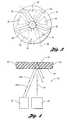
- FIG. 2is an elevational view partially broken away in section and taken along the direction of line 2 — 2 in FIG. 1 to illustrate the manner in which the container thicknesses are measured.
- FIG. 3is a bottom plan view of the container and also illustrates a path along which the thicknesses are inspected.
- FIG. 4is a schematic view similar to FIG. 2 but taken on an enlarged scale to illustrate the manner in which the container thickness is inspected.
- a blow molding systemgenerally indicated by 10 includes a blow molding machine 12 which is illustrated as being a machine that blow molds injection molded preforms which are heated in an oven 14 that is fed from an unshown supply of preforms.
- Inspection apparatus 16is constructed in accordance with the present invention to provide up to 100 percent inspection of the thickness of containers 18 that are blow molded by the machine 12 , with the inspection being performed just after the blow molding as is hereinafter more fully described. The method and apparatus of the invention will be described in an integrated manner to facilitate an understanding of all aspects of the invention.
- inspection apparatus 16 and its method of operationhave particular utility when utilized with reheat type injection stretch blow molding of containers, it is also possible to utilize the inspection apparatus with other types of blow molding systems such as extrusion blow molding, preform injection molding and immediate blow molding without cooling, etc.
- the inspection apparatusincludes a conveyor 20 for conveying blow molded containers along a path of conveyance P that is initially rotary and subsequently straight as is hereinafter more fully described.
- the inspection apparatus 16also includes a laser source 22 which, as shown in FIG. 2, directs a laser beam 24 toward the conveyed containers 18 so as to impinge along an inspection path 26 as shown in FIG. 3 .
- This laser beam 24 as illustrated in FIGS. 2 and 4is directed from the exterior of the conveyed containers 18 toward the container exteriors and is reflected at an outer surface 28 of each container as well as being reflected at an inner surface 30 of the container.
- a detector 32 of the apparatusdetects the laser beam 24 r-o reflected from the outer container surface 28 and also detects the laser beam 24 r-i reflected from the inner surface 30 and, by the spacing between these reflected beams, the detector determines the thickness of the container along the inspected path.
- An actuator 33 of the inspection apparatusis operable to remove from the conveyor 20 any containers which do not meet a design specification such as the container 18 r shown.
- the specific container 18 that is inspectedis made by a reheat type injection stretch blow molding operation utilizing polyethylene terephthalate resin. Furthermore, the container 18 is illustrated as being made with a freestanding bottom 34 for supporting the container upright on a horizontal support surface.
- This freestanding bottom 34includes a plurality of circumferentially spaced feet 36 , five as illustrated, alternating with curved straps 38 of which there are also five in number.
- the type of container involvedis more specifically disclosed in U.S. Pat. No. 5,064,080 of Young et al.
- the conveyor 20conveys the containers 18 upright with their bottoms 34 facing downwardly and the laser source 22 directs the laser beam 24 upwardly so that the inspected path 26 shown in FIG. 3 is along the container bottom.
- the inspection apparatus as disclosedthus detects the thickness of the container bottoms and removes any containers which do not meet the design specification.
- the conveyor 20includes a rotary wheel 40 that initially receives the blow molded containers 18 just after being blow molded by the machine 12 , and the container also includes a linear run 42 along which the containers are conveyed after the inspection.
- the actuator 33is illustrated as removing the rejected containers 18 r along the linear run 42 , it may also possible for the containers to be removed while on the rotary wheel 40 before reaching the linear run.
- the wheel 40receives the containers 18 in an oriented manner about a central vertical axis of the container, which is possible due to the configuration of the feet 36 and straps 38 of the container bottom 34 .
- a constant speed rotary drive 44drives the wheel 40 at a constant speed
- the laser source 22directs the laser beam 24 upwardly toward the containers while they are still on the rotary wheel 40 .
- the orientation of the conveyed containers and the constant speed driving of the wheel 40results in the inspected path 26 shown in FIG. 3 being the same on each container.
Landscapes
- Physics & Mathematics (AREA)
- General Physics & Mathematics (AREA)
- Length Measuring Devices By Optical Means (AREA)
- Blow-Moulding Or Thermoforming Of Plastics Or The Like (AREA)
Abstract
Description
Claims (2)
Priority Applications (4)
| Application Number | Priority Date | Filing Date | Title |
|---|---|---|---|
| US09/533,465US6693275B1 (en) | 2000-03-23 | 2000-03-23 | Method and apparatus for inspecting blow molded containers |
| CA002340965ACA2340965C (en) | 2000-03-23 | 2001-03-19 | Method and apparatus for inspecting blow molded containers |
| BRPI0101134-0ABR0101134B1 (en) | 2000-03-23 | 2001-03-22 | process and apparatus for inspecting blow molded containers. |
| MXPA01003062AMXPA01003062A (en) | 2000-03-23 | 2001-03-23 | Method and apparatus for inspecting blow molded containers. |
Applications Claiming Priority (1)
| Application Number | Priority Date | Filing Date | Title |
|---|---|---|---|
| US09/533,465US6693275B1 (en) | 2000-03-23 | 2000-03-23 | Method and apparatus for inspecting blow molded containers |
Publications (1)
| Publication Number | Publication Date |
|---|---|
| US6693275B1true US6693275B1 (en) | 2004-02-17 |
Family
ID=24126061
Family Applications (1)
| Application Number | Title | Priority Date | Filing Date |
|---|---|---|---|
| US09/533,465Expired - LifetimeUS6693275B1 (en) | 2000-03-23 | 2000-03-23 | Method and apparatus for inspecting blow molded containers |
Country Status (4)
| Country | Link |
|---|---|
| US (1) | US6693275B1 (en) |
| BR (1) | BR0101134B1 (en) |
| CA (1) | CA2340965C (en) |
| MX (1) | MXPA01003062A (en) |
Cited By (5)
| Publication number | Priority date | Publication date | Assignee | Title |
|---|---|---|---|---|
| US7010863B1 (en)* | 2004-01-26 | 2006-03-14 | Owens-Brockway Glass Container Inc. | Optical inspection apparatus and method for inspecting container lean |
| US9532009B1 (en)* | 2013-04-10 | 2016-12-27 | The Boeing Company | Systems and methods for detecting contaminants using laser beam path length differences |
| EP3404357A1 (en)* | 2017-05-18 | 2018-11-21 | Tech Pro Packag S.L. | Method and apparatus for the control of containers |
| CN112706386A (en)* | 2021-01-21 | 2021-04-27 | 丁伟烨 | Efficient forming bottle blowing machine based on pressure stabilizing device |
| CN115178477A (en)* | 2022-09-09 | 2022-10-14 | 张家港市意久机械有限公司 | Defect detection device for blow-molded product |
Citations (15)
| Publication number | Priority date | Publication date | Assignee | Title |
|---|---|---|---|---|
| US3328593A (en)* | 1963-07-29 | 1967-06-27 | Owens Illinois Inc | Apparatus for measuring the wall thickness of glass containers |
| US3994599A (en) | 1974-01-23 | 1976-11-30 | Owens-Illinois, Inc. | Method and apparatus for measuring wall thickness and concentricity of tubular glass articles |
| US4908507A (en) | 1986-03-10 | 1990-03-13 | Ovegipari Muvek | Process and apparatus for the integral optical examinations of damaging mechanical stresses in the bottom-part of bottles and hollow glassware |
| US5064080A (en) | 1990-11-15 | 1991-11-12 | Plastipak Packaging, Inc. | Plastic blow molded freestanding container |
| US5289266A (en)* | 1989-08-14 | 1994-02-22 | Hughes Aircraft Company | Noncontact, on-line determination of phosphate layer thickness and composition of a phosphate coated surface |
| US5291271A (en)* | 1992-08-19 | 1994-03-01 | Owens-Brockway Glass Container Inc. | Measurement of transparent container wall thickness |
| US5305081A (en) | 1992-08-27 | 1994-04-19 | Constar Plastics Inc. | Bottle stress analysis system |
| US5466927A (en) | 1994-04-08 | 1995-11-14 | Owens-Brockway Glass Container Inc. | Inspection of translucent containers |
| US5510610A (en) | 1994-10-07 | 1996-04-23 | Emhart Glass Machinery Investments Inc. | Apparatus for detecting defects on the bottom of bottles by manipulating an image to remove knurls |
| US5519204A (en) | 1994-04-25 | 1996-05-21 | Cyberoptics Corporation | Method and apparatus for exposure control in light-based measurement instruments |
| US5528026A (en) | 1993-10-08 | 1996-06-18 | Elpatronic Ag | Process and arrangement for the inspection of translucent articles |
| US5650851A (en) | 1995-06-26 | 1997-07-22 | National Research Council Of Canada | Speckle interference method for remote thickness measurement of a sheet and layer and an apparatus therefor |
| US5657124A (en) | 1994-02-18 | 1997-08-12 | Saint Gobain Cinematique Et Controle | Method of measuring the thickness of a transparent material |
| US5675516A (en) | 1995-09-27 | 1997-10-07 | Inex Vision Systems, Inc. | System and method for determining pushup of a molded glass container |
| US6172355B1 (en)* | 1998-10-13 | 2001-01-09 | Owens-Brockway Glass Container Inc. | In-line inspection of containers |
- 2000
- 2000-03-23USUS09/533,465patent/US6693275B1/ennot_activeExpired - Lifetime
- 2001
- 2001-03-19CACA002340965Apatent/CA2340965C/ennot_activeExpired - Lifetime
- 2001-03-22BRBRPI0101134-0Apatent/BR0101134B1/ennot_activeIP Right Cessation
- 2001-03-23MXMXPA01003062Apatent/MXPA01003062A/enactiveIP Right Grant
Patent Citations (16)
| Publication number | Priority date | Publication date | Assignee | Title |
|---|---|---|---|---|
| US3328593A (en)* | 1963-07-29 | 1967-06-27 | Owens Illinois Inc | Apparatus for measuring the wall thickness of glass containers |
| US3994599A (en) | 1974-01-23 | 1976-11-30 | Owens-Illinois, Inc. | Method and apparatus for measuring wall thickness and concentricity of tubular glass articles |
| US4908507A (en) | 1986-03-10 | 1990-03-13 | Ovegipari Muvek | Process and apparatus for the integral optical examinations of damaging mechanical stresses in the bottom-part of bottles and hollow glassware |
| US5289266A (en)* | 1989-08-14 | 1994-02-22 | Hughes Aircraft Company | Noncontact, on-line determination of phosphate layer thickness and composition of a phosphate coated surface |
| US5064080A (en) | 1990-11-15 | 1991-11-12 | Plastipak Packaging, Inc. | Plastic blow molded freestanding container |
| US5291271A (en)* | 1992-08-19 | 1994-03-01 | Owens-Brockway Glass Container Inc. | Measurement of transparent container wall thickness |
| US5305081A (en) | 1992-08-27 | 1994-04-19 | Constar Plastics Inc. | Bottle stress analysis system |
| US5528026A (en) | 1993-10-08 | 1996-06-18 | Elpatronic Ag | Process and arrangement for the inspection of translucent articles |
| US5657124A (en) | 1994-02-18 | 1997-08-12 | Saint Gobain Cinematique Et Controle | Method of measuring the thickness of a transparent material |
| US5466927A (en) | 1994-04-08 | 1995-11-14 | Owens-Brockway Glass Container Inc. | Inspection of translucent containers |
| US5519204A (en) | 1994-04-25 | 1996-05-21 | Cyberoptics Corporation | Method and apparatus for exposure control in light-based measurement instruments |
| US5665958A (en) | 1994-04-25 | 1997-09-09 | Cyberoptics Corporation | Method and apparatus for exposure control in light-based measurement instruments |
| US5510610A (en) | 1994-10-07 | 1996-04-23 | Emhart Glass Machinery Investments Inc. | Apparatus for detecting defects on the bottom of bottles by manipulating an image to remove knurls |
| US5650851A (en) | 1995-06-26 | 1997-07-22 | National Research Council Of Canada | Speckle interference method for remote thickness measurement of a sheet and layer and an apparatus therefor |
| US5675516A (en) | 1995-09-27 | 1997-10-07 | Inex Vision Systems, Inc. | System and method for determining pushup of a molded glass container |
| US6172355B1 (en)* | 1998-10-13 | 2001-01-09 | Owens-Brockway Glass Container Inc. | In-line inspection of containers |
Cited By (6)
| Publication number | Priority date | Publication date | Assignee | Title |
|---|---|---|---|---|
| US7010863B1 (en)* | 2004-01-26 | 2006-03-14 | Owens-Brockway Glass Container Inc. | Optical inspection apparatus and method for inspecting container lean |
| US9532009B1 (en)* | 2013-04-10 | 2016-12-27 | The Boeing Company | Systems and methods for detecting contaminants using laser beam path length differences |
| EP3404357A1 (en)* | 2017-05-18 | 2018-11-21 | Tech Pro Packag S.L. | Method and apparatus for the control of containers |
| CN112706386A (en)* | 2021-01-21 | 2021-04-27 | 丁伟烨 | Efficient forming bottle blowing machine based on pressure stabilizing device |
| CN115178477A (en)* | 2022-09-09 | 2022-10-14 | 张家港市意久机械有限公司 | Defect detection device for blow-molded product |
| CN115178477B (en)* | 2022-09-09 | 2022-11-29 | 张家港市意久机械有限公司 | For blow-moulded articles defect detecting apparatus of |
Also Published As
| Publication number | Publication date |
|---|---|
| MXPA01003062A (en) | 2004-07-30 |
| BR0101134A (en) | 2001-10-30 |
| BR0101134B1 (en) | 2013-02-19 |
| CA2340965C (en) | 2006-08-22 |
| CA2340965A1 (en) | 2001-09-23 |
Similar Documents
| Publication | Publication Date | Title |
|---|---|---|
| CN1189309C (en) | Automated Material Distribution Control for Stretch Blow Molded Articles | |
| EP1348932B1 (en) | Method and apparatus for monitoring wall thickness of blow-molded plastic containers | |
| US3848742A (en) | Glass container inspection machine | |
| US7858942B2 (en) | Method and device for monitoring wall thickness | |
| CN107107448B (en) | For conveying the device and method of preform in the region of blow moulding machine | |
| US11648726B2 (en) | Method and a device for inspecting a process of forming plastic preforms into plastic containers and in particular plastic bottles | |
| CN105799734B (en) | Rail vehicle wheel detection means and method | |
| US6693275B1 (en) | Method and apparatus for inspecting blow molded containers | |
| CN109029875B (en) | Crack detection device for glass wine bottle | |
| JP2002514525A (en) | Apparatus and method for manufacturing plastic hollow body | |
| WO2009072968A1 (en) | Method and arrangement for log classification | |
| CN103459117B (en) | Compression molding system | |
| CN115178477A (en) | Defect detection device for blow-molded product | |
| AU1670901A (en) | Method and apparatus for inspection of hot glass containers | |
| EP2120006B1 (en) | Out-of-round container detection system and method | |
| CA2401598C (en) | Blow-moulding plant with apparatus for automatic burst detection in blow-moulded containers | |
| JP2000158527A (en) | Inspection method in aseptic filling bottle manufacturing process | |
| CN207107078U (en) | A kind of packaging for foodstuff checkout system | |
| KR102428724B1 (en) | Defect rate detection system of biodegradable integrated film sheet container production equipment with laser thickness measurement function | |
| JP4815244B2 (en) | Bottle inspection machine and bottle making equipment | |
| CA2561594A1 (en) | Apparatus for blow moulding of plastic objects | |
| CN206356281U (en) | Bottle embryo detection rejecting machine | |
| CN222610402U (en) | Device for heating plastic preforms and device for producing plastic containers | |
| CN221559045U (en) | Detection structure for bottle cap injection molding machine | |
| JP2003004648A (en) | Inspection system for inner surface of plastic bottle |
Legal Events
| Date | Code | Title | Description |
|---|---|---|---|
| AS | Assignment | Owner name:PLASTIPAK PACKAGING, INC., MICHIGAN Free format text:ASSIGNMENT OF ASSIGNORS INTEREST;ASSIGNORS:STORK, WILMER D.;MCGAULEY, FRANKLIN C.;REEL/FRAME:010643/0134 Effective date:20000320 | |
| STCF | Information on status: patent grant | Free format text:PATENTED CASE | |
| AS | Assignment | Owner name:COMERICA BANK, AS AGENT, MICHIGAN Free format text:AMENDED AND RESTATED SECURITY AGREEMENT;ASSIGNORS:PLASTIPAK HOLDINGS, INC.;PLASTIPAK PACKAGING, INC.;WHITELINE EXPRESS, LTD.;AND OTHERS;REEL/FRAME:016418/0001 Effective date:20050128 | |
| FPAY | Fee payment | Year of fee payment:4 | |
| REMI | Maintenance fee reminder mailed | ||
| FPAY | Fee payment | Year of fee payment:8 | |
| SULP | Surcharge for late payment | Year of fee payment:7 | |
| REMI | Maintenance fee reminder mailed | ||
| FPAY | Fee payment | Year of fee payment:12 | |
| SULP | Surcharge for late payment | Year of fee payment:11 | |
| AS | Assignment | Owner name:WELLS FARGO BANK, N.A., AS ADMINISTRATIVE AGENT, VIRGINIA Free format text:SECURITY INTEREST;ASSIGNOR:PLASTIPAK PACKAGING, INC.;REEL/FRAME:044204/0547 Effective date:20171012 Owner name:WELLS FARGO BANK, N.A., AS ADMINISTRATIVE AGENT, V Free format text:SECURITY INTEREST;ASSIGNOR:PLASTIPAK PACKAGING, INC.;REEL/FRAME:044204/0547 Effective date:20171012 | |
| AS | Assignment | Owner name:CLEAN TECH, INC., MICHIGAN Free format text:RELEASE BY SECURED PARTY;ASSIGNOR:COMERICA BANK, AS AGENT;REEL/FRAME:044485/0515 Effective date:20171012 Owner name:PLASTIPAK HOLDINGS, INC., MICHIGAN Free format text:RELEASE BY SECURED PARTY;ASSIGNOR:COMERICA BANK, AS AGENT;REEL/FRAME:044485/0515 Effective date:20171012 Owner name:TABB REALTY, LLC, MICHIGAN Free format text:RELEASE BY SECURED PARTY;ASSIGNOR:COMERICA BANK, AS AGENT;REEL/FRAME:044485/0515 Effective date:20171012 Owner name:WHITELINE EXPRESS, LTD., MICHIGAN Free format text:RELEASE BY SECURED PARTY;ASSIGNOR:COMERICA BANK, AS AGENT;REEL/FRAME:044485/0515 Effective date:20171012 Owner name:PLASTIPAK PACKAGING, INC., MICHIGAN Free format text:RELEASE BY SECURED PARTY;ASSIGNOR:COMERICA BANK, AS AGENT;REEL/FRAME:044485/0515 Effective date:20171012 |