US6692660B2 - High luminescence phosphor particles and related particle compositions - Google Patents
High luminescence phosphor particles and related particle compositionsDownload PDFInfo
- Publication number
- US6692660B2 US6692660B2US09/843,195US84319501AUS6692660B2US 6692660 B2US6692660 B2US 6692660B2US 84319501 AUS84319501 AUS 84319501AUS 6692660 B2US6692660 B2US 6692660B2
- Authority
- US
- United States
- Prior art keywords
- particles
- collection
- metal
- rare earth
- percent
- Prior art date
- Legal status (The legal status is an assumption and is not a legal conclusion. Google has not performed a legal analysis and makes no representation as to the accuracy of the status listed.)
- Expired - Lifetime, expires
Links
- 239000002245particleSubstances0.000titleclaimsabstractdescription238
- OAICVXFJPJFONN-UHFFFAOYSA-NPhosphorusChemical compound[P]OAICVXFJPJFONN-UHFFFAOYSA-N0.000titledescription38
- 239000000203mixtureSubstances0.000titledescription23
- 238000004020luminiscence typeMethods0.000titledescription7
- 229910052751metalInorganic materials0.000claimsabstractdescription80
- 239000002184metalSubstances0.000claimsabstractdescription80
- 229910052752metalloidInorganic materials0.000claimsabstractdescription75
- 150000002738metalloidsChemical class0.000claimsabstractdescription66
- 229910052761rare earth metalInorganic materials0.000claimsabstractdescription54
- 150000002910rare earth metalsChemical class0.000claimsabstractdescription53
- 238000009826distributionMethods0.000claimsdescription18
- 239000011164primary particleSubstances0.000claimsdescription18
- 229910052693EuropiumInorganic materials0.000claimsdescription13
- OGPBJKLSAFTDLK-UHFFFAOYSA-Neuropium atomChemical compound[Eu]OGPBJKLSAFTDLK-UHFFFAOYSA-N0.000claimsdescription13
- 229910044991metal oxideInorganic materials0.000claimsdescription11
- 150000004706metal oxidesChemical class0.000claimsdescription11
- JQPIKACKMZSIJX-UHFFFAOYSA-Naluminum magnesium barium(2+) oxygen(2-)Chemical compound[O-2].[Al+3].[Mg+2].[Ba+2]JQPIKACKMZSIJX-UHFFFAOYSA-N0.000claimsdescription10
- 239000002019doping agentSubstances0.000claimsdescription9
- HCHKCACWOHOZIP-UHFFFAOYSA-NZincChemical compound[Zn]HCHKCACWOHOZIP-UHFFFAOYSA-N0.000claimsdescription4
- 229910052782aluminiumInorganic materials0.000claimsdescription4
- XAGFODPZIPBFFR-UHFFFAOYSA-NaluminiumChemical compound[Al]XAGFODPZIPBFFR-UHFFFAOYSA-N0.000claimsdescription4
- 229910052725zincInorganic materials0.000claimsdescription4
- 239000011701zincSubstances0.000claimsdescription4
- 239000000376reactantSubstances0.000abstractdescription121
- 239000007789gasSubstances0.000abstractdescription78
- 239000002243precursorSubstances0.000abstractdescription59
- 238000000034methodMethods0.000abstractdescription30
- QVGXLLKOCUKJST-UHFFFAOYSA-Natomic oxygenChemical compound[O]QVGXLLKOCUKJST-UHFFFAOYSA-N0.000abstractdescription18
- 229910052760oxygenInorganic materials0.000abstractdescription17
- 239000001301oxygenSubstances0.000abstractdescription17
- 229910001404rare earth metal oxideInorganic materials0.000abstractdescription14
- 238000006243chemical reactionMethods0.000description100
- 238000001725laser pyrolysisMethods0.000description71
- 239000000463materialSubstances0.000description40
- 239000000443aerosolSubstances0.000description33
- 238000004519manufacturing processMethods0.000description33
- 238000010438heat treatmentMethods0.000description31
- 239000002105nanoparticleSubstances0.000description27
- 239000011261inert gasSubstances0.000description25
- XKRFYHLGVUSROY-UHFFFAOYSA-NArgonChemical compound[Ar]XKRFYHLGVUSROY-UHFFFAOYSA-N0.000description24
- 238000012545processingMethods0.000description23
- 239000000047productSubstances0.000description21
- 239000012298atmosphereSubstances0.000description20
- 150000001875compoundsChemical class0.000description18
- 230000015572biosynthetic processEffects0.000description16
- 238000013459approachMethods0.000description15
- 230000008569processEffects0.000description15
- 229910052786argonInorganic materials0.000description14
- 239000007788liquidSubstances0.000description14
- 230000001590oxidative effectEffects0.000description14
- -1metalloid sulfidesChemical class0.000description13
- 238000000197pyrolysisMethods0.000description13
- XLYOFNOQVPJJNP-UHFFFAOYSA-NwaterSubstancesOXLYOFNOQVPJJNP-UHFFFAOYSA-N0.000description13
- KFZMGEQAYNKOFK-UHFFFAOYSA-NIsopropanolChemical compoundCC(C)OKFZMGEQAYNKOFK-UHFFFAOYSA-N0.000description12
- 239000012071phaseSubstances0.000description12
- 239000000243solutionSubstances0.000description12
- 239000012190activatorSubstances0.000description11
- 239000007787solidSubstances0.000description11
- 229910001868waterInorganic materials0.000description11
- 239000013078crystalSubstances0.000description10
- 239000011521glassSubstances0.000description10
- 238000002347injectionMethods0.000description9
- 239000007924injectionSubstances0.000description9
- 239000004973liquid crystal related substanceSubstances0.000description9
- 239000000758substrateSubstances0.000description9
- IJGRMHOSHXDMSA-UHFFFAOYSA-NAtomic nitrogenChemical compoundN#NIJGRMHOSHXDMSA-UHFFFAOYSA-N0.000description8
- 230000005284excitationEffects0.000description8
- 239000002904solventSubstances0.000description8
- JIAARYAFYJHUJI-UHFFFAOYSA-Lzinc dichlorideChemical compound[Cl-].[Cl-].[Zn+2]JIAARYAFYJHUJI-UHFFFAOYSA-L0.000description8
- 239000012159carrier gasSubstances0.000description7
- 230000005855radiationEffects0.000description7
- 238000003786synthesis reactionMethods0.000description7
- VGGSQFUCUMXWEO-UHFFFAOYSA-NEtheneChemical compoundC=CVGGSQFUCUMXWEO-UHFFFAOYSA-N0.000description6
- 239000006096absorbing agentSubstances0.000description6
- 238000013461designMethods0.000description6
- YIXJRHPUWRPCBB-UHFFFAOYSA-Nmagnesium nitrateChemical compound[Mg+2].[O-][N+]([O-])=O.[O-][N+]([O-])=OYIXJRHPUWRPCBB-UHFFFAOYSA-N0.000description6
- 239000000843powderSubstances0.000description6
- 229910002651NO3Inorganic materials0.000description5
- NHNBFGGVMKEFGY-UHFFFAOYSA-NNitrateChemical compound[O-][N+]([O-])=ONHNBFGGVMKEFGY-UHFFFAOYSA-N0.000description5
- 125000000219ethylidene groupChemical group[H]C(=[*])C([H])([H])[H]0.000description5
- 150000002500ionsChemical class0.000description5
- 239000011572manganeseSubstances0.000description5
- 150000002739metalsChemical class0.000description5
- 239000007858starting materialSubstances0.000description5
- 229910052984zinc sulfideInorganic materials0.000description5
- OKTJSMMVPCPJKN-UHFFFAOYSA-NCarbonChemical compound[C]OKTJSMMVPCPJKN-UHFFFAOYSA-N0.000description4
- LFQSCWFLJHTTHZ-UHFFFAOYSA-NEthanolChemical compoundCCOLFQSCWFLJHTTHZ-UHFFFAOYSA-N0.000description4
- 238000003917TEM imageMethods0.000description4
- XLOMVQKBTHCTTD-UHFFFAOYSA-NZinc monoxideChemical compound[Zn]=OXLOMVQKBTHCTTD-UHFFFAOYSA-N0.000description4
- PNEYBMLMFCGWSK-UHFFFAOYSA-Naluminium oxideInorganic materials[O-2].[O-2].[O-2].[Al+3].[Al+3]PNEYBMLMFCGWSK-UHFFFAOYSA-N0.000description4
- VSCWAEJMTAWNJL-UHFFFAOYSA-Kaluminium trichlorideChemical compoundCl[Al](Cl)ClVSCWAEJMTAWNJL-UHFFFAOYSA-K0.000description4
- 239000011230binding agentSubstances0.000description4
- 238000002844meltingMethods0.000description4
- 230000008018meltingEffects0.000description4
- 229910052757nitrogenInorganic materials0.000description4
- 238000010791quenchingMethods0.000description4
- 229910019901yttrium aluminum garnetInorganic materials0.000description4
- 239000011592zinc chlorideSubstances0.000description4
- OKKJLVBELUTLKV-UHFFFAOYSA-NMethanolChemical compoundOCOKKJLVBELUTLKV-UHFFFAOYSA-N0.000description3
- UCKMPCXJQFINFW-UHFFFAOYSA-NSulphideChemical compound[S-2]UCKMPCXJQFINFW-UHFFFAOYSA-N0.000description3
- 229920006362Teflon®Polymers0.000description3
- 238000002441X-ray diffractionMethods0.000description3
- XHCLAFWTIXFWPH-UHFFFAOYSA-N[O-2].[O-2].[O-2].[O-2].[O-2].[V+5].[V+5]Chemical compound[O-2].[O-2].[O-2].[O-2].[O-2].[V+5].[V+5]XHCLAFWTIXFWPH-UHFFFAOYSA-N0.000description3
- 229910052799carbonInorganic materials0.000description3
- 230000007423decreaseEffects0.000description3
- 238000010348incorporationMethods0.000description3
- 230000003993interactionEffects0.000description3
- 230000003287optical effectEffects0.000description3
- 229920000642polymerPolymers0.000description3
- 230000000171quenching effectEffects0.000description3
- 239000006100radiation absorberSubstances0.000description3
- 238000005245sinteringMethods0.000description3
- 238000001228spectrumMethods0.000description3
- 229910001935vanadium oxideInorganic materials0.000description3
- VXEGSRKPIUDPQT-UHFFFAOYSA-N4-[4-(4-methoxyphenyl)piperazin-1-yl]anilineChemical compoundC1=CC(OC)=CC=C1N1CCN(C=2C=CC(N)=CC=2)CC1VXEGSRKPIUDPQT-UHFFFAOYSA-N0.000description2
- KLZUFWVZNOTSEM-UHFFFAOYSA-KAluminium flourideChemical compoundF[Al](F)FKLZUFWVZNOTSEM-UHFFFAOYSA-K0.000description2
- ZOXJGFHDIHLPTG-UHFFFAOYSA-NBoronChemical compound[B]ZOXJGFHDIHLPTG-UHFFFAOYSA-N0.000description2
- 229910052684CeriumInorganic materials0.000description2
- 229910004664Cerium(III) chlorideInorganic materials0.000description2
- MYMOFIZGZYHOMD-UHFFFAOYSA-NDioxygenChemical compoundO=OMYMOFIZGZYHOMD-UHFFFAOYSA-N0.000description2
- 229910052691ErbiumInorganic materials0.000description2
- 239000005977EthyleneSubstances0.000description2
- WHXSMMKQMYFTQS-UHFFFAOYSA-NLithiumChemical compound[Li]WHXSMMKQMYFTQS-UHFFFAOYSA-N0.000description2
- 229910052771TerbiumInorganic materials0.000description2
- BOTDANWDWHJENH-UHFFFAOYSA-NTetraethyl orthosilicateChemical compoundCCO[Si](OCC)(OCC)OCCBOTDANWDWHJENH-UHFFFAOYSA-N0.000description2
- MCMNRKCIXSYSNV-UHFFFAOYSA-NZirconium dioxideChemical compoundO=[Zr]=OMCMNRKCIXSYSNV-UHFFFAOYSA-N0.000description2
- 239000003570airSubstances0.000description2
- 239000003513alkaliSubstances0.000description2
- WDIHJSXYQDMJHN-UHFFFAOYSA-Lbarium chlorideChemical compound[Cl-].[Cl-].[Ba+2]WDIHJSXYQDMJHN-UHFFFAOYSA-L0.000description2
- 229910001626barium chlorideInorganic materials0.000description2
- IWOUKMZUPDVPGQ-UHFFFAOYSA-Nbarium nitrateChemical compound[Ba+2].[O-][N+]([O-])=O.[O-][N+]([O-])=OIWOUKMZUPDVPGQ-UHFFFAOYSA-N0.000description2
- 230000004888barrier functionEffects0.000description2
- 229910052796boronInorganic materials0.000description2
- 239000000919ceramicSubstances0.000description2
- ZMIGMASIKSOYAM-UHFFFAOYSA-NceriumChemical compound[Ce][Ce][Ce][Ce][Ce][Ce][Ce][Ce][Ce][Ce][Ce][Ce][Ce][Ce][Ce][Ce][Ce][Ce][Ce][Ce][Ce][Ce][Ce][Ce][Ce][Ce][Ce][Ce][Ce][Ce][Ce][Ce][Ce][Ce][Ce][Ce][Ce][Ce]ZMIGMASIKSOYAM-UHFFFAOYSA-N0.000description2
- VYLVYHXQOHJDJL-UHFFFAOYSA-Kcerium trichlorideChemical compoundCl[Ce](Cl)ClVYLVYHXQOHJDJL-UHFFFAOYSA-K0.000description2
- 239000000460chlorineSubstances0.000description2
- 238000000576coating methodMethods0.000description2
- 239000003086colorantSubstances0.000description2
- 238000002485combustion reactionMethods0.000description2
- 239000011246composite particleSubstances0.000description2
- 239000000356contaminantSubstances0.000description2
- 238000011109contaminationMethods0.000description2
- 230000003247decreasing effectEffects0.000description2
- 239000008367deionised waterSubstances0.000description2
- 229910021641deionized waterInorganic materials0.000description2
- 239000003085diluting agentSubstances0.000description2
- 229910001882dioxygenInorganic materials0.000description2
- 239000002270dispersing agentSubstances0.000description2
- 239000006185dispersionSubstances0.000description2
- 230000000694effectsEffects0.000description2
- 230000005684electric fieldEffects0.000description2
- 238000005401electroluminescenceMethods0.000description2
- 238000010894electron beam technologyMethods0.000description2
- UYAHIZSMUZPPFV-UHFFFAOYSA-NerbiumChemical compound[Er]UYAHIZSMUZPPFV-UHFFFAOYSA-N0.000description2
- GAGGCOKRLXYWIV-UHFFFAOYSA-Neuropium(3+);trinitrateChemical compound[Eu+3].[O-][N+]([O-])=O.[O-][N+]([O-])=O.[O-][N+]([O-])=OGAGGCOKRLXYWIV-UHFFFAOYSA-N0.000description2
- 230000004907fluxEffects0.000description2
- 230000006870functionEffects0.000description2
- MWFSXYMZCVAQCC-UHFFFAOYSA-Ngadolinium(iii) nitrateChemical compound[Gd+3].[O-][N+]([O-])=O.[O-][N+]([O-])=O.[O-][N+]([O-])=OMWFSXYMZCVAQCC-UHFFFAOYSA-N0.000description2
- 239000003365glass fiberSubstances0.000description2
- 150000004820halidesChemical class0.000description2
- 229910052734heliumInorganic materials0.000description2
- 238000005286illuminationMethods0.000description2
- AMGQUBHHOARCQH-UHFFFAOYSA-Nindium;oxotinChemical compound[In].[Sn]=OAMGQUBHHOARCQH-UHFFFAOYSA-N0.000description2
- 239000003701inert diluentSubstances0.000description2
- 239000011133leadSubstances0.000description2
- 230000000670limiting effectEffects0.000description2
- 239000012705liquid precursorSubstances0.000description2
- 229910052744lithiumInorganic materials0.000description2
- 238000005259measurementMethods0.000description2
- 229910003455mixed metal oxideInorganic materials0.000description2
- 239000003960organic solventSubstances0.000description2
- SIWVEOZUMHYXCS-UHFFFAOYSA-Noxo(oxoyttriooxy)yttriumChemical compoundO=[Y]O[Y]=OSIWVEOZUMHYXCS-UHFFFAOYSA-N0.000description2
- 238000000206photolithographyMethods0.000description2
- 238000005086pumpingMethods0.000description2
- 239000010453quartzSubstances0.000description2
- 230000002829reductive effectEffects0.000description2
- SBIBMFFZSBJNJF-UHFFFAOYSA-Nselenium;zincChemical compound[Se]=[Zn]SBIBMFFZSBJNJF-UHFFFAOYSA-N0.000description2
- VYPSYNLAJGMNEJ-UHFFFAOYSA-Nsilicon dioxideInorganic materialsO=[Si]=OVYPSYNLAJGMNEJ-UHFFFAOYSA-N0.000description2
- 239000005049silicon tetrachlorideSubstances0.000description2
- 238000003746solid phase reactionMethods0.000description2
- 238000010671solid-state reactionMethods0.000description2
- 239000010935stainless steelSubstances0.000description2
- 229910001220stainless steelInorganic materials0.000description2
- 230000003068static effectEffects0.000description2
- 239000000126substanceSubstances0.000description2
- 230000002194synthesizing effectEffects0.000description2
- GZCRRIHWUXGPOV-UHFFFAOYSA-Nterbium atomChemical compound[Tb]GZCRRIHWUXGPOV-UHFFFAOYSA-N0.000description2
- 238000004627transmission electron microscopyMethods0.000description2
- FAQYAMRNWDIXMY-UHFFFAOYSA-NtrichloroboraneChemical compoundClB(Cl)ClFAQYAMRNWDIXMY-UHFFFAOYSA-N0.000description2
- 238000013022ventingMethods0.000description2
- 229910052844willemiteInorganic materials0.000description2
- RUDFQVOCFDJEEF-UHFFFAOYSA-Nyttrium(III) oxideInorganic materials[O-2].[O-2].[O-2].[Y+3].[Y+3]RUDFQVOCFDJEEF-UHFFFAOYSA-N0.000description2
- 235000005074zinc chlorideNutrition0.000description2
- 239000011787zinc oxideSubstances0.000description2
- BNGXYYYYKUGPPF-UHFFFAOYSA-M(3-methylphenyl)methyl-triphenylphosphanium;chlorideChemical compound[Cl-].CC1=CC=CC(C[P+](C=2C=CC=CC=2)(C=2C=CC=CC=2)C=2C=CC=CC=2)=C1BNGXYYYYKUGPPF-UHFFFAOYSA-M0.000description1
- KXJGSNRAQWDDJT-UHFFFAOYSA-N1-acetyl-5-bromo-2h-indol-3-oneChemical compoundBrC1=CC=C2N(C(=O)C)CC(=O)C2=C1KXJGSNRAQWDDJT-UHFFFAOYSA-N0.000description1
- 1250000017312-cyanoethyl groupChemical group[H]C([H])(*)C([H])([H])C#N0.000description1
- NGDQQLAVJWUYSF-UHFFFAOYSA-N4-methyl-2-phenyl-1,3-thiazole-5-sulfonyl chlorideChemical compoundS1C(S(Cl)(=O)=O)=C(C)N=C1C1=CC=CC=C1NGDQQLAVJWUYSF-UHFFFAOYSA-N0.000description1
- QGZKDVFQNNGYKY-UHFFFAOYSA-NAmmoniaChemical compoundNQGZKDVFQNNGYKY-UHFFFAOYSA-N0.000description1
- ZAMOUSCENKQFHK-UHFFFAOYSA-NChlorine atomChemical compound[Cl]ZAMOUSCENKQFHK-UHFFFAOYSA-N0.000description1
- 229910052688GadoliniumInorganic materials0.000description1
- UFHFLCQGNIYNRP-UHFFFAOYSA-NHydrogenChemical compound[H][H]UFHFLCQGNIYNRP-UHFFFAOYSA-N0.000description1
- TWRXJAOTZQYOKJ-UHFFFAOYSA-LMagnesium chlorideChemical compound[Mg+2].[Cl-].[Cl-]TWRXJAOTZQYOKJ-UHFFFAOYSA-L0.000description1
- 229920000784NomexPolymers0.000description1
- 229910052777PraseodymiumInorganic materials0.000description1
- 206010070834SensitisationDiseases0.000description1
- BLRPTPMANUNPDV-UHFFFAOYSA-NSilaneChemical compound[SiH4]BLRPTPMANUNPDV-UHFFFAOYSA-N0.000description1
- XUIMIQQOPSSXEZ-UHFFFAOYSA-NSiliconChemical compound[Si]XUIMIQQOPSSXEZ-UHFFFAOYSA-N0.000description1
- 229920002472StarchPolymers0.000description1
- 229910052775ThuliumInorganic materials0.000description1
- 238000002083X-ray spectrumMethods0.000description1
- 229910009372YVO4Inorganic materials0.000description1
- 239000005083Zinc sulfideSubstances0.000description1
- 238000009825accumulationMethods0.000description1
- 230000003213activating effectEffects0.000description1
- 150000001298alcoholsChemical class0.000description1
- 239000000956alloySubstances0.000description1
- 229910045601alloyInorganic materials0.000description1
- SMZOGRDCAXLAAR-UHFFFAOYSA-Naluminium isopropoxideChemical compound[Al+3].CC(C)[O-].CC(C)[O-].CC(C)[O-]SMZOGRDCAXLAAR-UHFFFAOYSA-N0.000description1
- JLDSOYXADOWAKB-UHFFFAOYSA-Naluminium nitrateChemical compound[Al+3].[O-][N+]([O-])=O.[O-][N+]([O-])=O.[O-][N+]([O-])=OJLDSOYXADOWAKB-UHFFFAOYSA-N0.000description1
- JPUHCPXFQIXLMW-UHFFFAOYSA-Naluminium triethoxideChemical compoundCCO[Al](OCC)OCCJPUHCPXFQIXLMW-UHFFFAOYSA-N0.000description1
- 239000012080ambient airSubstances0.000description1
- 239000006117anti-reflective coatingSubstances0.000description1
- 229910052787antimonyInorganic materials0.000description1
- WATWJIUSRGPENY-UHFFFAOYSA-Nantimony atomChemical compound[Sb]WATWJIUSRGPENY-UHFFFAOYSA-N0.000description1
- 229910052785arsenicInorganic materials0.000description1
- RQNWIZPPADIBDY-UHFFFAOYSA-Narsenic atomChemical compound[As]RQNWIZPPADIBDY-UHFFFAOYSA-N0.000description1
- JRPBQTZRNDNNOP-UHFFFAOYSA-Nbarium titanateChemical compound[Ba+2].[Ba+2].[O-][Ti]([O-])([O-])[O-]JRPBQTZRNDNNOP-UHFFFAOYSA-N0.000description1
- 229910002113barium titanateInorganic materials0.000description1
- 239000002585baseSubstances0.000description1
- 230000005540biological transmissionEffects0.000description1
- 229910052794bromiumInorganic materials0.000description1
- 238000005136cathodoluminescenceMethods0.000description1
- 239000007795chemical reaction productSubstances0.000description1
- 239000003795chemical substances by applicationSubstances0.000description1
- 238000005229chemical vapour depositionMethods0.000description1
- 150000003841chloride saltsChemical class0.000description1
- 229910052801chlorineInorganic materials0.000description1
- 239000011248coating agentSubstances0.000description1
- 230000001427coherent effectEffects0.000description1
- 210000001072colonAnatomy0.000description1
- 238000004891communicationMethods0.000description1
- 230000001010compromised effectEffects0.000description1
- 238000010276constructionMethods0.000description1
- 238000010924continuous productionMethods0.000description1
- 238000001816coolingMethods0.000description1
- 229910052593corundumInorganic materials0.000description1
- ZOCHARZZJNPSEU-UHFFFAOYSA-NdiboronChemical compoundB#BZOCHARZZJNPSEU-UHFFFAOYSA-N0.000description1
- HQWPLXHWEZZGKY-UHFFFAOYSA-NdiethylzincChemical compoundCC[Zn]CCHQWPLXHWEZZGKY-UHFFFAOYSA-N0.000description1
- AXAZMDOAUQTMOW-UHFFFAOYSA-NdimethylzincChemical compoundC[Zn]CAXAZMDOAUQTMOW-UHFFFAOYSA-N0.000description1
- 238000006073displacement reactionMethods0.000description1
- 238000000921elemental analysisMethods0.000description1
- 238000005516engineering processMethods0.000description1
- HDGGAKOVUDZYES-UHFFFAOYSA-Kerbium(iii) chlorideChemical compoundCl[Er](Cl)ClHDGGAKOVUDZYES-UHFFFAOYSA-K0.000description1
- KCWYOFZQRFCIIE-UHFFFAOYSA-NethylsilaneChemical compoundCC[SiH3]KCWYOFZQRFCIIE-UHFFFAOYSA-N0.000description1
- GEIGXJHXQWKQAT-UHFFFAOYSA-Neuropium;nitric acidChemical compound[Eu].O[N+]([O-])=OGEIGXJHXQWKQAT-UHFFFAOYSA-N0.000description1
- 238000004880explosionMethods0.000description1
- 239000012530fluidSubstances0.000description1
- 229910052731fluorineInorganic materials0.000description1
- 239000003517fumeSubstances0.000description1
- UIWYJDYFSGRHKR-UHFFFAOYSA-Ngadolinium atomChemical compound[Gd]UIWYJDYFSGRHKR-UHFFFAOYSA-N0.000description1
- 238000010574gas phase reactionMethods0.000description1
- 229910002804graphiteInorganic materials0.000description1
- 239000010439graphiteSubstances0.000description1
- 229910052736halogenInorganic materials0.000description1
- 150000002367halogensChemical class0.000description1
- 229910001385heavy metalInorganic materials0.000description1
- 239000001257hydrogenSubstances0.000description1
- 229910052739hydrogenInorganic materials0.000description1
- 239000012535impuritySubstances0.000description1
- 229910052740iodineInorganic materials0.000description1
- 239000006193liquid solutionSubstances0.000description1
- 229910003002lithium saltInorganic materials0.000description1
- 159000000002lithium saltsChemical class0.000description1
- 229910001635magnesium fluorideInorganic materials0.000description1
- WPBNNNQJVZRUHP-UHFFFAOYSA-Lmanganese(2+);methyl n-[[2-(methoxycarbonylcarbamothioylamino)phenyl]carbamothioyl]carbamate;n-[2-(sulfidocarbothioylamino)ethyl]carbamodithioateChemical compound[Mn+2].[S-]C(=S)NCCNC([S-])=S.COC(=O)NC(=S)NC1=CC=CC=C1NC(=S)NC(=O)OCWPBNNNQJVZRUHP-UHFFFAOYSA-L0.000description1
- 239000011159matrix materialSubstances0.000description1
- 150000002736metal compoundsChemical class0.000description1
- 150000002737metalloid compoundsChemical class0.000description1
- JLUFWMXJHAVVNN-UHFFFAOYSA-NmethyltrichlorosilaneChemical compoundC[Si](Cl)(Cl)ClJLUFWMXJHAVVNN-UHFFFAOYSA-N0.000description1
- 238000001000micrographMethods0.000description1
- 229910052754neonInorganic materials0.000description1
- GKAOGPIIYCISHV-UHFFFAOYSA-Nneon atomChemical compound[Ne]GKAOGPIIYCISHV-UHFFFAOYSA-N0.000description1
- 229910052756noble gasInorganic materials0.000description1
- 239000004763nomexSubstances0.000description1
- 229910052755nonmetalInorganic materials0.000description1
- 150000002843nonmetalsChemical class0.000description1
- 238000000059patterningMethods0.000description1
- 230000035515penetrationEffects0.000description1
- 238000005424photoluminescenceMethods0.000description1
- 229920001343polytetrafluoroethylenePolymers0.000description1
- 239000004810polytetrafluoroethyleneSubstances0.000description1
- PUDIUYLPXJFUGB-UHFFFAOYSA-Npraseodymium atomChemical compound[Pr]PUDIUYLPXJFUGB-UHFFFAOYSA-N0.000description1
- 230000002265preventionEffects0.000description1
- 239000002994raw materialSubstances0.000description1
- 230000035484reaction timeEffects0.000description1
- 230000006798recombinationEffects0.000description1
- 238000005215recombinationMethods0.000description1
- 230000004044responseEffects0.000description1
- 238000007650screen-printingMethods0.000description1
- 230000008313sensitizationEffects0.000description1
- 238000000926separation methodMethods0.000description1
- 229910052710siliconInorganic materials0.000description1
- 239000010703siliconSubstances0.000description1
- LIVNPJMFVYWSIS-UHFFFAOYSA-Nsilicon monoxideChemical compound[Si-]#[O+]LIVNPJMFVYWSIS-UHFFFAOYSA-N0.000description1
- 239000012686silicon precursorSubstances0.000description1
- 229910052709silverInorganic materials0.000description1
- 239000004332silverSubstances0.000description1
- 229910052950sphaleriteInorganic materials0.000description1
- 239000012798spherical particleSubstances0.000description1
- 238000005507sprayingMethods0.000description1
- 238000004544sputter depositionMethods0.000description1
- 239000008107starchSubstances0.000description1
- 235000019698starchNutrition0.000description1
- 150000004763sulfidesChemical class0.000description1
- SFZCNBIFKDRMGX-UHFFFAOYSA-Nsulfur hexafluorideChemical compoundFS(F)(F)(F)(F)FSFZCNBIFKDRMGX-UHFFFAOYSA-N0.000description1
- 238000001308synthesis methodMethods0.000description1
- 229910052714telluriumInorganic materials0.000description1
- PORWMNRCUJJQNO-UHFFFAOYSA-Ntellurium atomChemical compound[Te]PORWMNRCUJJQNO-UHFFFAOYSA-N0.000description1
- GFISHBQNVWAVFU-UHFFFAOYSA-Kterbium(iii) chlorideChemical compoundCl[Tb](Cl)ClGFISHBQNVWAVFU-UHFFFAOYSA-K0.000description1
- VCZQFJFZMMALHB-UHFFFAOYSA-NtetraethylsilaneChemical compoundCC[Si](CC)(CC)CCVCZQFJFZMMALHB-UHFFFAOYSA-N0.000description1
- 238000012546transferMethods0.000description1
- 230000009466transformationEffects0.000description1
- 238000000844transformationMethods0.000description1
- 229910052723transition metalInorganic materials0.000description1
- 150000003624transition metalsChemical class0.000description1
- WOZZOSDBXABUFO-UHFFFAOYSA-Ntri(butan-2-yloxy)alumaneChemical compound[Al+3].CCC(C)[O-].CCC(C)[O-].CCC(C)[O-]WOZZOSDBXABUFO-UHFFFAOYSA-N0.000description1
- MYWQGROTKMBNKN-UHFFFAOYSA-NtributoxyalumaneChemical compound[Al+3].CCCC[O-].CCCC[O-].CCCC[O-]MYWQGROTKMBNKN-UHFFFAOYSA-N0.000description1
- DWAWYEUJUWLESO-UHFFFAOYSA-NtrichloromethylsilaneChemical compound[SiH3]C(Cl)(Cl)ClDWAWYEUJUWLESO-UHFFFAOYSA-N0.000description1
- ZDHXKXAHOVTTAH-UHFFFAOYSA-NtrichlorosilaneChemical compoundCl[SiH](Cl)ClZDHXKXAHOVTTAH-UHFFFAOYSA-N0.000description1
- 239000005052trichlorosilaneSubstances0.000description1
- ZSDSQXJSNMTJDA-UHFFFAOYSA-NtrifluralinChemical compoundCCCN(CCC)C1=C([N+]([O-])=O)C=C(C(F)(F)F)C=C1[N+]([O-])=OZSDSQXJSNMTJDA-UHFFFAOYSA-N0.000description1
- 239000012808vapor phaseSubstances0.000description1
- 238000009423ventilationMethods0.000description1
- 239000002699waste materialSubstances0.000description1
- 229910052724xenonInorganic materials0.000description1
- FHNFHKCVQCLJFQ-UHFFFAOYSA-Nxenon atomChemical compound[Xe]FHNFHKCVQCLJFQ-UHFFFAOYSA-N0.000description1
- 229910001845yogo sapphireInorganic materials0.000description1
- ONDPHDOFVYQSGI-UHFFFAOYSA-Nzinc nitrateChemical compound[Zn+2].[O-][N+]([O-])=O.[O-][N+]([O-])=OONDPHDOFVYQSGI-UHFFFAOYSA-N0.000description1
- JRPGMCRJPQJYPE-UHFFFAOYSA-Nzinc;carbanideChemical compound[CH3-].[CH3-].[Zn+2]JRPGMCRJPQJYPE-UHFFFAOYSA-N0.000description1
- IPSRAFUHLHIWAR-UHFFFAOYSA-Nzinc;ethaneChemical compound[Zn+2].[CH2-]C.[CH2-]CIPSRAFUHLHIWAR-UHFFFAOYSA-N0.000description1
- DRDVZXDWVBGGMH-UHFFFAOYSA-Nzinc;sulfideChemical compound[S-2].[Zn+2]DRDVZXDWVBGGMH-UHFFFAOYSA-N0.000description1
Images


Classifications
- C—CHEMISTRY; METALLURGY
- C09—DYES; PAINTS; POLISHES; NATURAL RESINS; ADHESIVES; COMPOSITIONS NOT OTHERWISE PROVIDED FOR; APPLICATIONS OF MATERIALS NOT OTHERWISE PROVIDED FOR
- C09K—MATERIALS FOR MISCELLANEOUS APPLICATIONS, NOT PROVIDED FOR ELSEWHERE
- C09K11/00—Luminescent, e.g. electroluminescent, chemiluminescent materials
- C09K11/08—Luminescent, e.g. electroluminescent, chemiluminescent materials containing inorganic luminescent materials
- C09K11/77—Luminescent, e.g. electroluminescent, chemiluminescent materials containing inorganic luminescent materials containing rare earth metals
- C09K11/7783—Luminescent, e.g. electroluminescent, chemiluminescent materials containing inorganic luminescent materials containing rare earth metals containing two or more rare earth metals one of which being europium
- C09K11/7792—Aluminates
Definitions
- the inventionrelates to method for synthesizing metal/metalloid oxide particles with rare earth metals, especially metal/metalloid oxides with fluorescent properties.
- the inventionrelates to submicron metal/metalloid oxide particles with rare earth metals and displays produced from these particles.
- Phosphor materialswhich emit visible light in response to interaction with electrons.
- Phosphor materialscan be applied to substrates to produce cathode ray tubes, flat panel displays and the like. Improvements in display devices place stringent demands on the phosphor materials, for example, due to decreases in electron velocity and increases in display resolution. Electron velocity is reduced in order to reduce power demands.
- flat panel displaysgenerally require phosphors that are responsive to low velocity electrons or low voltages.
- a desire for color displayrequires the use of materials or combinations of materials that emit light at different wavelengths at positions in the display that can be selectively excited.
- materialshave been used as phosphors.
- activatorshave been doped into phosphor material.
- multiple phosphorscan be mixed to obtain the desired emission.
- the phosphor materialsmust show sufficient luminescence.
- Various metal compositionsexhibit desired phosphorescent properties upon excitation. Specifically, various metal oxides, including rare earth metal oxides exhibit fluorescence. In addition, doping of rare earth metals into non-rare earth metal oxides can be used to adjust the wavelength and luminosity of the phosphor particles.
- the inventionin a first aspect, pertains to a method for producing metal/metalloid oxide particles comprising rare earth metals.
- the methodincludes reacting a reactant stream in a gas flow wherein the reaction is driven by energy from a light beam.
- the reactant streamcomprises a rare earth metal precursor and an oxygen source.
- the metal oxidescan also include a non-rare earth metal/metalloid by introducing a non-rare earth metal/metalloid precursor into the flow.
- the inventionpertains to a collection of particles comprising a metal/metalloid oxide having an average particle size from about 15 nm to about 1 micron.
- the metal/metalloid oxidecomprises a non-rare earth metal oxide wherein less than about 10 mole percent of a stoichiometric amount of a non-rare earth metal/metalloid is substituted with rare earth metal.
- the metal/metalloid oxide particlescan be used in a display device.
- the inventionin another aspect pertains to a collection of particles comprising barium magnesium aluminum oxide having an average particle size of less than 500 nm.
- the inventionpertains to a method of making a collection of metal/metalloid sulfides particles with an average particle size of less than about 500 nm.
- the methodcomprises contacting metal/metalloid oxide particles with H 2 S at a temperature below the melting temperature of the metal/metalloid oxide particles and the metal/metalloid sulfide particles.
- the metal/metalloid oxide particlehave an average particle size under 500 nm.
- the inventionpertains to a collection of rare earth doped metal/metalloid sulfide particles having an average particle size from about 15 nm to about 500 nm.
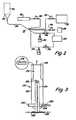
- FIG. 1is a schematic, sectional view of an embodiment of a laser pyrolysis apparatus, where the cross section is taken through the middle of the laser radiation path.
- the upper insertis a bottom view of the collection nozzle, and the lower insert is a top view of the injection nozzle.
- FIG. 2is a schematic, side view of a reactant delivery apparatus for the delivery of vapor reactants to the laser pyrolysis apparatus of FIG. 1 .
- FIG. 3is a schematic, sectional view of a reactant delivery apparatus for the delivery of an aerosol reactant to the laser pyrolysis apparatus of FIG. 1, the cross section being taken through the center of the apparatus.
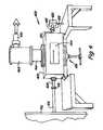
- FIG. 4is a perspective view of an alternative embodiment of a laser pyrolysis apparatus.
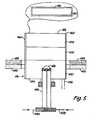
- FIG. 5is a sectional view of the inlet nozzle of the alternative laser pyrolysis apparatus of FIG. 4, the cross section being taken along the length of the nozzle through its center.
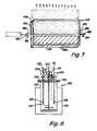
- FIG. 6is a sectional view of the inlet nozzle of the alternative laser pyrolysis apparatus of FIG. 4, the cross section being taken along the width of the nozzle through its center.
- FIG. 7is a perspective view of an embodiment of an elongated reaction chamber for performing laser pyrolysis.
- FIG. 8is a schematic, sectional view of an apparatus for heat treating nanoparticles, in which the section is taken through the center of the apparatus.
- FIG. 9is a schematic, sectional view of an oven for heating nanoparticles, in which the section is taken through the center of a tube.
- FIG. 10is a sectional view of an embodiment of display device incorporating a phosphor layer.
- FIG. 11is a sectional view of an embodiment of a liquid crystal display incorporating a phosphor for illumination.
- FIG. 12is a sectional view of an electroluminescent display.
- FIG. 13is a sectional view of an embodiment of a flat panel display incorporating field emission display devices.
- FIG. 14is a sectional view of elements of a plasma display panel.
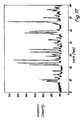
- FIG. 15is an x-ray diffractogram of a sample of europium doped barium magnesium aluminum oxide produced by laser pyrolysis.
- FIG. 16is an x-ray diffractogram of a sample of europium doped barium magnesium aluminum oxide produced by laser pyrolysis produced under different conditions that used to produce the sample of FIG. 15 .
- FIG. 17is an x-ray diffractogram of a first sample produced by laser pyrolysis following a heat treatment.
- FIG. 18is an x-ray diffractogram of a second sample produced by laser pyrolysis following a heat treatment.
- FIG. 19is a transmission electron micrograph of a powder used to generate the x-ray diffractogram in FIG. 17 .
- FIG. 20is an x-ray diffractogram of two samples of (Y 0.95 Eu 0.05 ) 2 O 3 produced by laser pyrolysis.
- Rare earth metal/metalloid sulfides and rare earth doped metal/metalloid sulfidescan be formed from, respectively, the rare earth metal oxides or the rare earth doped metal/metalloid oxides.
- the resulting particlesare suitable for use as phosphors, which can be used for the production of displays.
- the particleshave submicron average particles sizes and high luminoscities.
- the rare earth metalsare dopants that displace corresponding non-rare earth metals/metalloids from the metal/metalloid oxide or metal/metalloid sulfide lattice.
- the particlescan include stoichiometric amounts of rare earth metal, alone or in combination with other metals/metalloids.
- Submicron metal oxide particles with various stoichiometries and crystal structurescan be produced by pyrolysis, especially laser pyrolysis, alone or with additional processing.
- approacheshave been developed for the synthesis of multiple metal oxide composite particles.
- the plurality of metalsare introduced into the reactant stream. It has been discovered that these approaches can be generalized for the production of rare earth metal oxides, mixed metal/metalloid rare earth oxides and rare earth doped metal/metalloid oxides.
- submicron particles incorporating the desired metal/metalloid oxide stoichiometrycan be formed.
- Preferred collections of metal/metalloid oxide particleshave an average diameter less than a micron and high uniformity with a narrow distribution of particle diameters.
- laser pyrolysiscan be used either alone or in combination with additional processing, such as heat processing. Specifically, laser pyrolysis has been found to be an excellent process for efficiently producing submicron (less than about 1 micron average diameter) and nanoscale (less than about 100 nm average diameter) metal/metalloid oxide particles with a narrow distribution of average particle diameters.
- submicron metal/metalloid oxide particles produced by laser pyrolysiscan be subjected to heating under mild conditions in an oxygen environment or an inert environment to alter the crystal properties and/or the stoichiometry of the particles.
- a large variety of different types of metal/metalloid oxide particlescan be produced using these approaches.
- a basic feature of successful application of laser pyrolysis for the production of metal/metalloid oxide particlesis production of a reactant stream containing one or more appropriate metal/metalloid precursors.
- a source of atomic oxygenis required.
- the atomic oxygencan be bonded within the metal/metalloid precursors and/or can be supplied by a separate oxygen source, such as molecular oxygen.
- a separate oxygen sourcesuch as molecular oxygen.
- an additional radiation absorberis added to the reactant stream.
- the reactant streamis pyrolyzed by an intense light beam, such as a laser beam. While a laser beam is a convenient energy source, other intense light sources can be used in laser pyrolysis.
- Laser pyrolysisprovides for formation of phases of materials that are difficult to form under thermodynamic equilibrium conditions. As the reactant stream leaves the light beam, the metal/metalloid oxide particles are rapidly quenched.
- laser pyrolysisis a preferred approach for producing submicron metal/metalloid oxide particles.
- other approaches involving flowing reactant streamscan be used to synthesize submicron metal/metalloid oxide particles for the improved production approaches for producing metal/metalloid oxides with rare earth metals.
- Suitable alternative approachesinclude, for example, flame pyrolysis and thermal pyrolysis. Flame pyrolysis can be performed with a hydrogen-oxygen flame, wherein the flame supplies the energy to drive the pyrolysis.
- Such a flame pyrolysis approachshould produce similar materials as the laser pyrolysis techniques herein, except that flame pyrolysis approaches generally do not produce comparable high uniformity and a narrow particle size distribution that can be obtained by laser pyrolysis.
- a suitable flame production apparatusis described in U.S. Pat. No. 5,447,708 to Helble et al., entitled “Apparatus for Producing Nanoscale Ceramic Particles,” incorporated herein by reference.
- submicron particlescan be produced by adapting the laser pyrolysis methods with a thermal reaction chamber such as the apparatus described in U.S. Pat. No. 4,842,832 to Inoue et al., “Ultrafine Spherical Particles of Metal Oxide and a Method for the Production Thereof,” incorporated herein by reference.
- phosphorsare synthesized by solid state reactions between raw materials at high temperatures.
- phosphorsinvolve a host crystal with an activator.
- the activatoris used to increase luminosity and alter the luminescent color of the phosphors.
- the activatorsgenerally take the form of a dopant that is introduced into the host crystal at low mole fractions.
- Other materials, called fluxcan be added to facilitate the solid state reaction and to form well crystallized particles.
- Fluxed that have been usedinclude alkali halides, such as KF, and alkali earth halides, such as MgF 2 , and other non-transition metal halides, such as AlF 3 .
- the laser pyrolysis approach with subsequent heat treatmentdoes not require a flux.
- Preferred phosphorsinclude a host crystal or matrix and a small amount of activator. Generally, heavy metal ions or rare earth ions are used as activators. In some phosphors, co-activators are also added for charge compensation. For example, with zinc sulfide host crystals, group IIIa ions (e.g., Al +3 ) or group VIIb ions (e.g., Mn) are used as co-activators. Co-activator ions help to form the luminescent center, while the luminescent spectrum is almost independent of the composition of the co-activator. Energy transfer processes are often used in commercial phosphors to enhance emission efficiency. The process is called sensitization of luminescence, and the energy donor is called a sensitizer. For example, the emission intensity of Mn +2 activated sulfide phosphors are sensitized by Pb +2 , Sb +3 and Ce +3 .
- the particlesAfter the production of the particles by laser pyrolysis, generally it is desirable to heat treat the particles.
- Qualities of the oxide particlescan be altered by heat treating the initially synthesized particles.
- the crystallinity and/or the phase purity of the particlescan be altered by heat treatment.
- the heat treatmentcan be performed in an oxidizing atmosphere, a reducing atmosphere or an inert atmosphere to produce the desired resulting particles.
- corresponding sulfide particlescan be formed by a thermal process.
- the oxide particlesare heated while in contact with a sulfuring atmosphere formed by, for example, H 2 S or CS 2 .
- the resulting submicron and especially nanoscale metal/metalloid oxides and metal/metalloid sulfideshave high luminosity. These particles are particularly useful for the production of electronic displays. Because of the small size of the particles, the fluorescence can be stimulated by lower voltages.
- laser pyrolysisis a valuable tool for the production of submicron and nanoscale metal/metalloid oxide particles.
- Other chemical reaction synthesis methods for producing rare earth metal oxide particles using a flowing reactant stream in a gas floware discussed above.
- the reactant delivery approaches described belowcan be adapted for producing metal/metalloid oxide particles with rare earth metals generally in flow reactant systems, with or without a light source.
- Laser pyrolysisis a preferred approach for synthesizing the rare earth metal oxide particles because laser pyrolysis produces highly uniform and high quality product particles.
- the reaction conditionsdetermine the qualities of the particles produced by laser pyrolysis.
- the reaction conditions for laser pyrolysiscan be controlled relatively precisely in order to produce particles with desired properties.
- the appropriate reaction conditions to produce a certain type of particlesgenerally depend on the design of the particular apparatus. Specific conditions used to produce rare earth metal oxide particles in a particular apparatus are described below in the Examples. Furthermore, some general observations on the relationship between reaction conditions and the resulting particles can be made.
- Reactant flow rate and velocity of the reactant gas streamare inversely related to particle size so that increasing the reactant gas flow rate or velocity tends to result in smaller particle sizes.
- Light poweralso influences particle size with increased light power favoring larger particle formation for lower melting materials and smaller particle formation for higher melting materials.
- the growth dynamics of the particleshave a significant influence on the size of the resulting particles. In other words, different forms of a product compound have a tendency to form different size particles from other phases under relatively similar conditions. Similarly, in multiphase regions at which populations of particles with different compositions are formed, each population of particles generally has its own characteristic narrow distribution of particle sizes.
- Laser pyrolysishas become the standard terminology for chemical reactions driven by a intense light radiation with rapid quenching of product after leaving a narrow reaction region defined by the light.
- the nameis a misnomer in the sense that a strong, incoherent, but focused light beam can replace the laser.
- the reactionis not a pyrolysis in the sense of a thermal pyrolysis.
- the laser pyrolysis reactionis not thermally driven by the exothermic combustion of the reactants. In fact, some laser pyrolysis reactions can be conducted under conditions where no visible flame is observed from the reaction.
- Suitable host materials for the formation of phosphorsinclude, for example, ZnO, ZnS, Zn 2 SiO 4 , SrS, YBO 3 , Y 2 O 3 , Al 2 O 3 , Y 3 Al 5 O 12 and BaMgAl 14 O 23 .
- Preferred non-rare earth metals for activating phosphor particles as dopantsinclude, for example, manganese, silver and lead.
- Preferred rare earth metals for forming metal oxide phosphorsinclude, for example, europium, cerium, terbium and erbium. The reactant stream incorporates the appropriate blend of these metals.
- Metal pyrolysishas been performed generally with gas/vapor phase reactants.
- Many metal precursor compoundscan be delivered into the reaction chamber as a gas.
- Appropriate metal/metalloid precursor compounds for gaseous deliverygenerally include metal/metalloid compounds with reasonable vapor pressures, i.e., vapor pressures sufficient to get desired amounts of precursor gas/vapor into the reactant stream.
- the vessel holding liquid or solid precursor compoundscan be heated to increase the vapor pressure of the metal/metalloid precursor, if desired.
- Solid precursorsgenerally are heated to produce a sufficient vapor pressure.
- a carrier gascan be bubbled through a liquid precursor to facilitate delivery of a desired amount of precursor vapor.
- a carrier gascan be passed over the solid precursor to facilitate delivery of the precursor vapor.
- Suitable solid zinc precursors for vapor deliveryinclude, for example, zinc chloride (ZnCl 2 ).
- Suitable liquid zinc precursor compounds for vapor deliveryinclude, for example, diethyl zinc (Zn(C 2 H 5 ) 2 ) and dimethyl zinc (Zn(CH 3 ) 2 ).
- Suitable solid aluminum precursors for vapor deliveryinclude, for example, aluminum chloride (AlCl 3 ), aluminum ethoxide (Al(OC 2 H 5 ) 3 ), and aluminum isopropoxide (Al[OCH(CH 3 ) 2 ] 3 ).
- Suitable liquid, aluminum precursors for vapor deliveryinclude, for example, aluminum s-butoxide (Al(OC 4 H 9 ) 3 ).
- Suitable silicon precursors for vapor deliveryinclude, for example, silicon tetrachloride (SiCl 4 ), trichlorosilane (Cl 3 HSi), trichloromethyl silane CH 3 SiCl 3 , and tetraethoxysilane (Si(OC 2 H 5 ) 4 , also known as ethyl silane and tetraethyl silane).
- Suitable boron precursorsinclude, for example, boron trichloride (BCl 3 ), diborane (B 2 H 6 ), and BH 3 .
- the chlorine in these representative precursor compoundsgenerally can be replaced with other halogens, e.g., Br, I and F.
- solid precursor compoundscan be delivered by dissolving the compounds in a solvent.
- powdered precursor compoundscan be dispersed in a liquid/solvent for aerosol delivery.
- Liquid precursor compoundscan be delivered as an aerosol from a neat liquid, a multiple liquid dispersion or a liquid solution.
- Aerosol reactantscan be used to obtain a significant reactant throughput.
- a solvent/dispersantcan be selected to achieve desired properties of the resulting solution/dispersion. Suitable solvents/dispersants include water, methanol, ethanol, isopropyl alcohol, other organic solvents and mixtures thereof.
- the solventshould have a desired level of purity such that the resulting particles have a desired purity level.
- Some solvents, such as isopropyl alcoholare significant absorbers of infrared light from a CO 2 laser such that no additional laser absorbing compound may be needed within the reactant stream if a CO 2 laser is used as a light source.
- the solventpreferably is rapidly evaporated by the light beam in the reaction chamber such that a gas phase reaction can take place.
- the fundamental features of the laser pyrolysis reactionare unchanged by the presence of an aerosol. Nevertheless, the reaction conditions are affected by the presence of the aerosol. Below in the Examples, conditions are described for the production of nanoscale metal oxide particles using aerosol precursors in a particular laser pyrolysis reaction chamber. Thus, the parameters associated with aerosol reactant delivery can be explored further based on the description below.
- a number of suitable solid, non-rare earth metal/metalloid precursor compoundscan be delivered as an aerosol from solution.
- zinc chloride (ZnCl 2 ) and zinc nitrate (Zn(NO 3 ) 2 )are soluble in water and some organic solvents, such as isopropyl alcohol.
- Aluminum nitrate (Al(NO 3 ) 3 )is soluble in water.
- Barium chloride (BaCl 2 ) and barium nitrate (Ba(NO 3 ) 2 )are soluble in water.
- Magnesium nitrate (Mg(NO 3 ) 2 )is somewhat soluble in water and is freely soluble in alcohol, and magnesium chloride (MgCl 2 ) is somewhat soluble in water and alcohols.
- cerous chloride (CeCl 3 )is soluble in water.
- Europium nitrate (Eu(NO 3 ) 3 )is soluble in water.
- Gadolinium nitrate (Gd(NO 3 ) 3 )is soluble in water.
- Terbium chloride (TbCl 3 ) and erbium chloride (ErCl 3 )are soluble in water.
- the precursor compounds for aerosol deliveryare dissolved in a solution preferably with a concentration greater than about 0.5 molar.
- concentrationgreater than about 0.5 molar.
- concentrationgreater the concentration of precursor in the solution the greater the throughput of reactant through the reaction chamber.
- concentrationincreases, however, the solution can become more viscous such that the aerosol may have droplets with larger sizes than desired.
- selection of solution concentrationcan involve a balance of factors in the selection of a preferred solution concentration.
- Preferred secondary reactants serving as an oxygen sourceinclude, for example, O 2 , CO, H 2 O, CO 2 , O 3 and mixtures thereof. Molecular oxygen can be supplied as air.
- the secondary reactant compoundshould not react significantly with the metal/metalloid precursor prior to entering the reaction zone since this generally would result in the formation of large particles. If the reactants are spontaneously reactive, the metal/metalloid precursor and the secondary reactant can be delivered in separate nozzles into the reaction chamber such that they are combined just prior to reaching the light beam. If the metal/metalloid precursors includes oxygen, a secondary reactant may not be needed to supply oxygen.
- Laser pyrolysiscan be performed with a variety of optical frequencies, using either a laser or other strong focused light source.
- Preferred light sourcesoperate in the infrared portion of the electromagnetic spectrum.
- CO 2 lasersare particularly preferred sources of light.
- Infrared absorbers for inclusion in the reactant streaminclude, for example, C 2 H 4 , isopropyl alcohol, NH 3 , SF 6 , SiH 4 and O 3 .
- O 3can act as both an infrared absorber and as an oxygen source.
- the radiation absorbersuch as the infrared absorber, absorbs energy from the radiation beam and distributes the energy to the other reactants to drive the pyrolysis.
- the energy absorbed from the light beamincreases the temperature at a tremendous rate, many times the rate that heat generally would be produced by exothermic reactions under controlled condition. While the process generally involves nonequilibrium conditions, the temperature can be described approximately based on the energy in the absorbing region.
- the laser pyrolysis processis qualitatively different from the process in a combustion reactor where an energy source initiates a reaction, but the reaction is driven by energy given off by an exothermic reaction. Thus, while the light driven process is referred to as laser pyrolysis, it is not a thermal process even though traditional pyrolysis is a thermal process.
- An inert shielding gascan be used to reduce the amount of reactant and product molecules contacting the reactant chamber components.
- Inert gasescan also be introduced into the reactant stream as a carrier gas and/or as a reaction moderator.
- Appropriate inert gasesinclude, for example, Ar, He and N 2 .
- An appropriate laser pyrolysis apparatusgenerally includes a reaction chamber isolated from the ambient environment.
- a reactant inlet connected to a reactant delivery apparatusproduces a reactant stream with a gas flow through the reaction chamber.
- a light beam pathintersects the reactant stream at a reaction zone.
- the reactant/product streamcontinues after the reaction zone to an outlet, where the reactant/product stream exits the reaction chamber and passes into a collection apparatus.
- the light sourcesuch as a laser, is located external to the reaction chamber, and the light beam enters the reaction chamber through an appropriate window.
- a particular embodiment 100 of a laser pyrolysis systeminvolves a reactant delivery apparatus 102 , reaction chamber 104 , shielding gas delivery apparatus 106 , collection apparatus 108 and light source 110 .
- a first reaction delivery apparatus described belowcan be used to deliver exclusively gaseous reactants.
- An alternative reactant delivery apparatusis described for delivery of one or more reactants as an aerosol.
- a first embodiment 112 of reactant delivery apparatus 102includes a source 120 of a precursor compound.
- a carrier gas from one or more carrier gas sources 122can be introduced into precursor source 120 to facilitate delivery of the reactant.
- Precursor source 120can be a liquid holding container, a solid precursor delivery apparatus or other suitable container.
- the carrier gas from carrier gas source 122preferably is either an infrared absorber and/or an inert gas.
- the gases from precursor source 120are mixed with gases from infrared absorber source 124 , inert gas source 126 and/or secondary reactant source 128 by combining the gases in a single portion of tubing 130 .
- the gasesare combined a sufficient distance from reaction chamber 104 such that the gases become well mixed prior to their entrance into reaction chamber 104 .
- the combined gas in tube 130passes through a duct 132 into channel 134 , which is in fluid communication with reactant inlet 256 (FIG. 1 ).
- a second reactantcan be supplied from second reactant source 138 , which can be a liquid reactant delivery apparatus, a solid reactant delivery apparatus, a gas cylinder or other suitable container or containers. As shown in FIG. 2, second reactant source 138 delivers a second reactant to duct 132 by way of tube 130 . Alternatively, mass flow controllers 146 can be used to regulate the flow of gases within the reactant delivery system of FIG. 2 . In alternative embodiments, the second reactant can be delivered through a second duct for delivery into the reactant chamber through a second channel such that the reactants do not mix until they are in the reaction chamber.
- a laser pyrolysis apparatus with a plurality of reactant delivery nozzlesis described further in copending and commonly assigned U.S. patent application Ser. No. 09/266,202 to Reitz et al., entitled “Zinc Oxide Particles,” incorporated herein by reference.
- the reactant streamcan include one or more aerosols.
- the aerosolscan be formed within reaction chamber 104 or outside of reaction chamber 104 prior to injection into reaction chamber 104 . If the aerosols are produced prior to injection into reaction chamber 104 , the aerosols can be introduced through reactant inlets comparable to those used for gaseous reactants, such as reactant inlet 134 in FIG. 2 .
- embodiment 210 of the reactant supply system 102can be used to supply an aerosol to duct 132 .
- Reactant supply system 210includes an outer nozzle 212 and an inner nozzle 214 .
- Outer nozzle 212has an upper channel 216 that leads to a rectangular outlet 218 at the top of outer nozzle 212 , as shown in the insert in FIG. 3 .
- Rectangular outlet 218has selected dimensions to produce a reactant stream of desired expanse within the reaction chamber.
- Outer nozzle 212includes a drain tube 220 in base plate 222 . Drain tube 220 is used to remove condensed aerosol from outer nozzle 212 .
- Inner nozzle 214is secured to outer nozzle 212 at fitting 224 .
- the top of inner nozzle 214preferably is a twin orifice internal mix atomizer 226 .
- Liquidis fed to the atomizer through tube 228 , and gases for introduction into the reaction chamber are fed to the atomizer through tube 230 . Interaction of the gas with the liquid assists with droplet formation.
- the reaction chamber 104includes a main chamber 250 .
- Reactant supply system 102connects to the main chamber 250 at injection nozzle 252 .
- Reaction chamber 104can be heated to a surface temperature above the dew point of the mixture of reactants and inert components at the pressure in the apparatus.
- the end of injection nozzle 252has an annular opening 254 for the passage of inert shielding gas, and a reactant inlet 256 (left lower insert) for the passage of reactants to form a reactant stream in the reaction chamber.
- Reactant inlet 256preferably is a slit, as shown in the lower inserts of FIG. 1 .
- Annular opening 254has, for example, a diameter of about 1.5 inches and a width along the radial direction from about 1 ⁇ 8 in to about ⁇ fraction (1/16) ⁇ in.
- the flow of shielding gas through annular opening 254helps to prevent the spread of the reactant gases and product particles throughout reaction chamber 104 .
- Tubular sections 260 , 262are located on either side of injection nozzle 252 .
- Tubular sections 260 , 262include, for example, ZnSe windows 264 , 266 , respectively.
- Windows 264 , 266are about 1 inch in diameter.
- Windows 264 , 266are preferably cylindrical lenses with a focal length equal to the distance between the center of the chamber to the surface of the lens to focus the light beam to a point just below the center of the nozzle opening.
- Windows 264 , 266preferably have an antireflective coating.
- Appropriate ZnSe lensesare available from Laser Power Optics, San Diego, Calif.
- Tubular sections 260 , 262provide for the displacement of windows 264 , 266 away from main chamber 250 such that windows 264 , 266 are less likely to be contaminated by reactants and/or products. Window 264 , 266 are displaced, for example, about 3 cm from the edge of the main chamber 250 .
- Windows 264 , 266are sealed with a rubber o-ring to tubular sections 260 , 262 to prevent the flow of ambient air into reaction chamber 104 .
- Tubular inlets 268 , 270provide for the flow of shielding gas into tubular sections 260 , 262 to reduce the contamination of windows 264 , 266 .
- Tubular inlets 268 , 270are connected to shielding gas delivery apparatus 106 .
- shielding gas delivery system 106includes inert gas source 280 connected to an inert gas duct 282 .
- Inert gas duct 282flows into annular channel 284 leading to annular opening 254 .
- a mass flow controller 286regulates the flow of inert gas into inert gas duct 282 .
- inert gas source 126can also function as the inert gas source for duct 282 , if desired.
- inert gas source 280 or a separate inert gas sourcecan be used to supply inert gas to tubes 268 , 270 .
- Flow to tubes 268 , 270preferably is controlled by a mass flow controller 288 .
- Light source 110is aligned to generate a light beam 300 that enters window 264 and exits window 266 .
- Windows 264 , 266define a light path through main chamber 250 intersecting the flow of reactants at reaction zone 302 .
- power meter 304which also acts as a beam dump.
- An appropriate power meteris available from Coherent Inc., Santa Clara, Calif.
- Light source 110can be a laser or an intense conventional light source such as an arc lamp.
- light source 110is an infrared laser, especially a CW CO 2 laser such as an 1800 watt maximum power output laser available from PRC Corp., Landing, N.J.
- Reactants passing through reactant inlet 256 in injection nozzle 252initiate a reactant stream.
- the reactant streampasses through reaction zone 302 , where reaction involving the metal/metalloid precursor compounds takes place. Heating of the gases in reaction zone 302 is extremely rapid, roughly on the order of 10 5 degree C./sec depending on the specific conditions.
- the reactionis rapidly quenched upon leaving reaction zone 302 , and particles 306 are formed in the reactant/product stream.
- the nonequilibrium nature of the processallows for the production of nanoparticles with a highly uniform size distribution and structural homogeneity.
- Collection nozzle 310has a circular opening 312 , as shown in the upper insert of FIG. 1 . Circular opening 312 feeds into collection system 108 .
- the chamber pressureis monitored with a pressure gauge 320 attached to the main chamber.
- the preferred chamber pressure for the production of the desired oxidesgenerally ranges from about 80 Torr to about 650 Torr.
- Collection system 108preferably includes a curved channel 330 leading from collection nozzle 310 . Because of the small size of the particles, the product particles follow the flow of the gas around curves. Collection system 108 includes a filter 332 within the gas flow to collect the product particles. Due to curved section 330 , the filter is not supported directly above the chamber.
- a variety of materialssuch as Teflon® (polytetrafluoroethylene), glass fibers and the like can be used for the filter as long as the material is inert and has a fine enough mesh to trap the particles.
- Preferred materials for the filterinclude, for example, a glass fiber filter from ACE Glass Inc., Vineland, N.J. and cylindrical Nomex® filters from AF Equipment Co., Sunnyvale, Calif.
- Pump 334is used to maintain collection system 108 at a selected pressure. It may be desirable to flow the exhaust of the pump through a scrubber 336 to remove any remaining reactive chemicals before venting into the atmosphere.
- the pumping rateis controlled by either a manual needle valve or an automatic throttle valve 338 inserted between pump 334 and filter 332 .
- the manual valve or the throttle valvecan be adjusted to maintain the pumping rate and the corresponding chamber pressure.
- the apparatusis controlled by a computer 350 .
- the computercontrols the light source and monitors the pressure in the reaction chamber.
- the computercan be used to control the flow of reactants and/or the shielding gas.
- the reactioncan be continued until sufficient particles are collected on filter 332 such that pump 334 can no longer maintain the desired pressure in the reaction chamber 104 against the resistance through filter 332 .
- the reactionis stopped, and filter 332 is removed.
- a single rungenerally can last up to about 10 hours depending on the reactant delivery system, the type of particle being produced and the type of filter being used.
- Laser pyrolysis apparatus 400includes a reaction chamber 402 .
- the reaction chamber 402has a shape of a rectangular parallelapiped. Reaction chamber 402 extends with its longest dimension along the laser beam. Reaction chamber 402 has a viewing window 404 at its side, such that the reaction zone can be observed during operation.
- Reaction chamber 402has tubular extensions 408 , 410 that define an optical path through the reaction chamber.
- Tubular extension 408is connected with a seal to a cylindrical lens 412 .
- Tube 414connects laser 416 or other optical source with lens 412 .
- Tubular extension 410is connected with a seal to tube 418 , which further leads to beam dump/light meter 420 .
- the entire light path from laser 416 to beam dump 420is enclosed.
- Inlet nozzle 426connects with reaction chamber 402 at its lower surface 428 .
- Inlet nozzle 426includes a plate 430 that bolts into lower surface 428 to secure inlet nozzle 426 .
- inlet nozzle 426includes an inner nozzle 432 and an outer nozzle 434 .
- Inner nozzle 432preferably has a twin orifice internal mix atomizer 436 at the top of the nozzle. Suitable gas atomizers are available from Spraying Systems, Wheaton, Ill.
- the twin orifice internal mix atomizer 436has a fan shape to produce a thin sheet of aerosol and gaseous precursors. Liquid is fed to the atomizer through tube 438 , and gases for introduction into the reaction chamber are fed to the atomizer through tube 440 . Interaction of the gas with the liquid assists with droplet formation.
- Outer nozzle 434includes a chamber section 450 , a funnel section 452 and a delivery section 454 .
- Chamber section 450holds the atomizer of inner nozzle 432 .
- Funnel section 452directs the aerosol and gaseous precursors into delivery section 454 .
- Delivery section 450leads to an about 3 inch by 0.5 inch rectangular outlet 456 , shown in the insert of FIG. 5 .
- Outer nozzle 434includes a drain 458 to remove any liquid that collects in the outer nozzle.
- Outer nozzle 434is covered by an outer wall 460 that forms an shielding gas opening 462 surrounding outlet 456 . Inert gas is introduced through inlet 464 .
- exit nozzle 466connects to apparatus 400 at the top surface of reaction chamber 402 .
- Exit nozzle 466leads to filter chamber 468 .
- Filter chamber 468connects with pipe 470 which leads to a pump.
- a cylindrical filteris mounted at the opening to pipe 470 . Suitable cylindrical filters are described above.
- the reaction chamber and reactant inletare elongated significantly along the light beam to provide for an increase in the throughput of reactants and products.
- the original design of the apparatuswas based on the introduction of purely gaseous reactants.
- the embodiments described above for the delivery of aerosol reactantscan be adapted for the elongated reaction chamber design. Additional embodiments for the introduction of an aerosol with one or more aqrosol generators into an elongated reaction chamber are described in commonly assigned and copending U.S. patent application Ser. No. 09/188,670, now U.S. Pat. No. 6,193,936 to Gardner et al., entitled “Reactant Delivery Apparatuses,” incorporated herein by reference.
- the laser pyrolysis apparatus with the elongated reaction chamber and reactant inletis designed to reduce contamination of the chamber walls, to increase the production capacity and to make efficient use of resources.
- the elongated reaction chamberprovides for an increased throughput of reactants and products without a corresponding increase in the dead volume of the chamber.
- the dead volume of the chambercan become contaminated with unreacted compounds and/or reaction products.
- an appropriate flow of shielding gasconfines the reactants and products within a flow stream through the reaction chamber. The high throughput of reactants makes efficient use of the laser energy.
- a reactant inlet 474leads to main chamber 476 .
- Reactant inlet 474conforms generally to the shape of main chamber 476 .
- Main chamber 476includes an outlet 478 along the reactant/product stream for removal of particulate products, any unreacted gases and inert gases.
- Shielding gas inlets 480are located on both sides of reactant inlet 474 . Shielding gas inlets are used to form a blanket of inert gases on the sides of the reactant stream to inhibit contact between the chamber walls and the reactants or products.
- the dimensions of elongated main chamber 476 and reactant inlet 474preferably are designed for high efficiency particle production.
- Reasonable lengths for reactant inlet 474 for the production of ceramic nanoparticles, when used with a 1800 watt CO 2 laser,are from about 5 mm to about 1 meter.
- Tubular sections 482 , 484extend from the main chamber 476 .
- Tubular sections 482 , 484hold windows 486 , 488 to define a light beam path 490 through the reaction chamber 472 .
- Tubular sections 482 , 484can include inert gas inlets 492 , 494 for the introduction of inert gas into tubular sections 482 , 484 .
- the improved reaction systemincludes a collection apparatus to remove the nanoparticles from the reactant stream.
- the collection systemcan be designed to collect particles in a batch mode with the collection of a large quantity of particles prior to terminating production.
- a filter or the likecan be used to collect the particles in batch mode.
- the collection systemcan be designed to run in a continuous production mode by switching between different particle collectors within the collection apparatus or by providing for removal of particles without exposing the collection system to the ambient atmosphere.
- a preferred embodiment of a collection apparatus for continuous particle productionis described in copending and commonly assigned U.S. patent application Ser. No. 09/107,729, now U.S. Pat. No. 6,270,732 to Gardner et al., entitled “Particle Collection Apparatus And Associated Methods,” incorporated herein by reference.
- Suitable starting material for the heat treatmentinclude particles produced by laser pyrolysis.
- particles used as starting material for a heat treatment processcan have been subjected to one or more prior heating steps under different conditions.
- the additional heat processingcan improve/alter the crystallinity, remove contaminants, such as elemental carbon, and/or alter the stoichiometry, for example, by incorporation of additional oxygen or removal of oxygen.
- mixed metal/metalloid oxides formed by laser pyrolysiscan be subjected to a heat processing step.
- This heat processingconverts these particles into desired high quality crystalline forms.
- the heat treatmentsubstantially maintains the submicron or nanoscale size and size uniformity of the particles from laser pyrolysis. In other words, particle size is not compromised significantly by thermal processing.
- the particlesare heated in an oven or the like to provide generally uniform heating.
- the processing conditionsgenerally are mild, such that significant amounts of particle sintering does not occur.
- the temperature of heatingpreferably is low relative to the melting point of the starting material and the product material.
- the atmosphere over the particlescan be static, or gases can be flowed through the system.
- the atmosphere for the heating processcan be an oxidizing atmosphere, a reducing atmosphere or an inert atmosphere.
- the atmospheregenerally can be inert.
- oxidizing gasesinclude, for example, O 2 , O 3 , CO, CO 2 , and combinations thereof.
- the O 2can be supplied as air.
- Reducing gasesinclude, for example, H 2 and NH 3 .
- a reducing atmosphereis used for the heat treatment of BaMgAl 14 O 23 doped with europeum since the europeum is generally supplied in a +3 state while it operates as the phosphor activator in a +2 state. Therefore, the have complete incorporation and improves phase uniformity, the particles generally are heat treated under a reducing atmosphere.
- Oxidizing gases or reducing gasesoptionally can be mixed with inert gases such as Ar, He and N 2 .
- the gas mixturecan include from about 1 percent oxidizing/reducing gas to about 99 percent oxidizing/reducing gas, and more preferably from about 5 percent oxidizing/reducing gas to about 99 percent oxidizing/reducing gas.
- either essentially pure oxidizing gas, pure reducing gas or pure inert gascan be used, as desired. Care must be taken with respect to the prevention of explosions when using highly concentrated reducing gases.
- the precise conditionscan be altered to vary the type of metal/metalloid oxide particles that are produced.
- the temperature, time of heating, heating and cooling rates, the surrounding gases and the exposure conditions with respect to the gasescan all be selected to produce desired product particles.
- the longer the heating periodthe more oxygen that is incorporated into the material, prior to reaching equilibrium.
- the overall conditionsdetermine the crystalline phase of the powders.
- Apparatus 500includes a jar 502 , which can be made from glass or other inert material, into which the particles are placed. Suitable glass reactor jars are available from Ace Glass (Vineland, N.J.). For higher temperatures alloy jars can be used to replace the glass jars.
- the top of glass jar 502is sealed to a glass cap 504 , with a Teflon® gasket 506 between jar 502 and cap 504 .
- Cap 504can be held in place with one or more clamps.
- Cap 504includes a plurality of ports 508 , each with a Teflon® bushing.
- a multiblade stainless steel stirrer 510preferably is inserted through a central port 508 in cap 504 . Stirrer 510 is connected to a suitable motor.
- Tubes 512are inserted through ports 508 for the delivery of gases into jar 502 .
- Tubes 512can be made from stainless steel or other inert material.
- Diffusers 514can be included at the tips of tubes 512 to disburse the gas within jar 502 .
- a heater/furnace 516generally is placed around jar 502 . Suitable resistance heaters are available from Glas-col (Terre Haute, Ind.).
- One portpreferably includes a T-connection 518 . The temperature within jar 502 can be measured with a thermocouple 518 inserted through T-connection 518 .
- T-connection 518can be further connected to a vent 520 .
- Vent 520provides for the venting of gas circulated through jar 502 .
- vent 520is vented to a fume hood or alternative ventilation equipment.
- desired gasesare flowed through jar 502 .
- Tubes 512generally are connected to an oxidizing gas source and/or an inert gas source. Oxidizing gas, inert gas or a combination thereof to produce the desired atmosphere are placed within jar 502 from the appropriate gas source(s).
- Various flow ratescan be used. The flow rate preferably is between about 1 standard cubic centimeters per minute (sccm) to about 1000 sccm and more preferably from about 10 sccm to about 500 sccm.
- the flow rategenerally is constant through the processing step, although the flow rate and the composition of the gas can be varied systematically over time during processing, if desired.
- a static gas atmospherecan be used.
- FIG. 9An alternative apparatus 530 for the heat treatment of modest quantities of nanoparticles is shown in FIG. 9 .
- the particlesare placed within a boat 532 or the like within tube 534 .
- Tube 534can be produced from, for example, quartz, alumina or zirconia.
- the desired gasesare flowed through tube 534 .
- Gasescan be supplied for example from inert gas source 536 or oxidizing gas source 538 .
- Tube 534is located within oven or furnace 540 .
- Oven 540can be adapted from a commercial furnace, such as Mini-MiteTM 1100° C. Tube Furnace from Lindberg/Blue M, Asheville, N.C. Oven 540 maintains the relevant portions of the tube at a relatively constant temperature, although the temperature can be varied systematically through the processing step, if desired. The temperature can be monitored with a thermocouple 542 .
- the temperaturepreferably ranges from about 400° C. to about 1400° C.
- the particular temperatureswill depend on the specific material being processed. The heating generally is continued for greater than about 5 minutes, and typically is continued for from about 10 minutes to about 120 hours, in most circumstances from about 10 minutes to about 5 hours. Preferred heating times also will depend on the particular starting material and target product. Some empirical adjustment may be helpful to produce the conditions appropriate for yielding a desired material.
- submicron and nanoscale powderscan be processed at lower temperatures while still achieving the desired reaction. The use of mild conditions avoids significant interparticle sintering resulting in larger particle sizes.
- the particlespreferably are heated for short periods of time at high temperatures or for longer periods of time at lower temperatures. Some controlled sintering of the particles can be performed at somewhat higher temperatures to produce slightly larger, average particle diameters.
- heat treatmentcan be used to perform a variety of desirable transformations for nanoparticles.
- the conditions to convert crystalline VO 2 to orthorbonibic V 2 O 5 and 2-D crystalline V 2 O 5 , and amorphous V 2 O 5 to orthorhombic V 2 O 5 and 2-D crystalline Y 2 O 5are describe in U.S. Pat. No. 5,989,514, to Bi St al., entitled “Processing of Vanadium Oxide Particles With Heat,” incorporated herein by reference.
- Conditions for the removal of carbon coatings from metal oxide nanoparticlesis described in copending and commonly assigned U.S. patent application Ser. No. 09/123,255 now U.S. Pat. No.
- metal/metalloid oxide particlescan be converted to the corresponding metal/metalloid sulfides by heating the oxide in a sulfurizing atmosphere formed by a H 2 S gas atmosphere or a CS 2 vapor atmosphere.
- the metal/metalloid oxidescan be heated gently to form the sulfide. Since the sulfides are extremely reactive, the heating can be very stricte, generally less than about 500° C., preferably less than about 500° C. and even more preferably less than about 300° C.
- Suitable concentrations of sulfurizing agent and reaction timescan be evaluated empirically by examining the x-ray diffractograms of the resulting materials or by performing an elemental analysis.
- a collection of particles of interestgenerally has an average diameter for the primary particles of less than about 1000 nm, in most embodiments less than about 500 nm, in other embodiments from about 2 nm to about 100 nm, in further embodiments from about 3 nm to about 75 nm, and still other embodiments from about 5 nm to about 50 nm.
- the average particle sizesrange from about 15 nm to about 100 nm, or from about 15 nm to about 50 nm.
- Particle diametersgenerally are evaluated by transmission electron microscopy. Diameter measurements on particles with asymmetries are based on an average of length measurements along the principle axes of the particle.
- the primary particlesusually have a roughly spherical gross appearance. With some precursors the particles produced by laser pyrolysis are porous and less spherical. Mild heat treatment of these porous particles leads to a more spherical solid particle. Generally, after heat treatment, the particles may be less spherical. Upon closer examination, crystalline particles generally have facets corresponding to the underlying crystal lattice. Nevertheless, crystalline primary particles tend to exhibit growth in laser pyrolysis that is roughly equal in the three physical dimensions to give a gross spherical appearance. Amorphous particles generally have an even more spherical aspect. In some embodiments, 95 percent of the primary particles, and preferably 99 percent, have ratios of the dimension along the major axis to the dimension along the minor axis less than about 2.
- the primary particlestend to form loose agglomerates due to van der Waals and other electromagnetic forces between nearby particles. These agglomerates can be dispersed to a significant degree, if desired. Even though the particles form loose agglomerates, the nanometer scale of the primary particles is clearly observable in transmission electron micrographs of the particles.
- the particlesgenerally have a surface area corresponding to particles on a nanometer scale as observed in the micrographs. Furthermore, the particles can manifest unique properties due to their small size and large surface area per weight of material.
- vanadium oxide nanoparticlescan exhibit surprisingly high energy densities in lithium batteries, as described in U.S. Pat. No. 5,952,125 to Bi et al., entitled “Batteries With Electroactive Nanoparticles,” incorporated herein by reference.
- the primary particlespreferably have a high degree of uniformity in size.
- Laser pyrolysisas described above, generally results in particles having a very narrow range of particle diameters.
- heat processing under suitably mild conditionsdoes not alter the very narrow range of particle diameters.
- aerosol delivery of reactants for laser pyrolysisthe distribution of particle diameters is particularly sensitive to the reaction conditions. Nevertheless, if the reaction conditions are properly controlled, a very narrow distribution of particle diameters can be obtained with an aerosol delivery system.
- the primary particlesgenerally have a distribution in sizes such that at least about 95 percent, and preferably 99 percent, of the primary particles have a diameter greater than about 40 percent of the average diameter and less than about 225 percent of the average diameter.
- the primary particleshave a distribution of diameters such that at least about 95 percent, and preferably 99 percent, of the primary particles have a diameter greater than about 45 percent of the average diameter and less than about 200 percent of the average diameter.
- no primary particleshave an average diameter greater than about 5 times the average diameter and preferably 4 times the average diameter, and more preferably 3 times the average diameter.
- the particle size distributioneffectively does not have a tail indicative of a small number of particles with significantly larger sizes. This is a result of the small reaction region and corresponding rapid quench of the particles.
- An effective cut off in the tail of the size distributionindicates that there are less than about 1 particle in 10 6 have a diameter greater than a specified cut off value above the average diameter. Narrow size distributions, lack of a tail in the distributions and the roughly spherical morphology can be exploited in a variety of applications.
- the nanoparticlesgenerally have a very high purity level.
- the nanoparticles produced by the above described methodsare expected to have a purity greater than the reactants because the laser pyrolysis reaction and, when applicable, the crystal formation process tends to exclude contaminants from the particle.
- crystalline nanoparticles produced by laser pyrolysishave a high degree of crystallinity.
- the crystalline nanoparticles produced by heat processinghave a high degree of crystallinity. Certain impurities on the surface of the particles may be removed by heating the particles to achieve not only high crystalline purity but high purity overall.
- the preferred metal/metalloid oxidesinclude rare earth metals.
- Preferred rare earth metals for use in phosphor particlesinclude, for example, europium, cerium, terbium, gadolinium, thulium, praseodymium and erbium.
- the metal oxidescan be rare earth metal oxides.
- rare earth metal oxides Z 2 O 3where Z is a rare earth metal, have been described as suitable phosphors. These phosphors can be produced by solution chemistry approaches as described in published PCT Application WO99/46204, entitled “Self Activated Rare Earth Oxide Nanoparticles,” incorporated herein by reference.
- the rare earth metalis a dopant that substitutes for a non-rare earth metal/metalloid and/or for another rare earth metal.
- Metalloidsare elements that exhibit chemical properties intermediate between or inclusive of metals and nonmetals. Metalloid elements include silicon, boron, arsenic, antimony, and tellurium.
- the dopantcan alter the light output and color of the material. Suitable red phosphors include, for example, YVO 4 :Eu, ZnS:Mn, YBO 3 :Eu, GdBO 3 :Eu, Y 2 O 3 :Eu, and Y 3 Al 5 O 12 :Eu.
- Suitable green phosphorsinclude, for example, ZnS:Tb, Zn 2 SiO 4 :Mn, Y 3 Al 5 O 12 :Tm, BaAl 12 O 19 :Mn and BaMgAl 14 O 23 :Mn.
- Suitable blue phosphorsinclude, for example, ZnS:Ag, SrS:Ce, BaMgAl 14 O 23 :Eu, BaMgAl 10 O 17 :Eu, and Y 3 Al 5 O 12 :Tb.
- the doping element indicated on the right of the colonsubstitutes in the crystal lattice for one or more of the other metals in the oxide.
- the rare earth metalgenerally is in the form of an ion with a charge from +2 to +4.
- the rare earth dopantWhen the rare earth metal is a dopant replacing either another rare earth metal or a non-rare earth metal/metalloid, the rare earth dopant generally comprises less than about 15 mole percent of the metal in the composition, in further embodiments less than about 10 mole percent, in some embodiments less than about 5 mole percent, in other embodiments from about 0.05 to about 1 mole percent of the metal/metalloid in the composition.
- the present disclosuresimilarly covers ranges within these specific ranges.
- the phosphorsemit light, preferably visible light, following excitation. Some useful materials emit light in the infrared portion of the light spectrum. A variety of ways can be used to excite the phosphors, and particular phosphors may be responsive to one or more of the excitation approaches. Particular types of luminescence include cathodoluminescence, photoluminescence and electroluminescence which, respectively, involve excitation by electrons, light and electric fields Many materials that are suitable as chathodoluminescence phosphors are also suitable as electroluminescence phosphors.
- the phosphor particlespreferably are suitable for low-velocity electron excitation, with electrons accelerated with potentials below 1 kilovolts (KV), and more preferably below 100 V.
- KVkilovolts
- the small size of the particlesmakes them suitable for low velocity electron excitation.
- Low energy electron excitationcan be used because the correspondingly lower penetration distances of the electrons are less limiting as the particle size decreases.
- nanoscale particlesproduce high luminescence with low electron velocity excitation.
- optimum luminositycan be expected from small sized particles, although an optimum particle size may be reached beyond which even smaller particle sizes can result in slightly reduced luminosity.
- the effects of decreasing particle size on phosphorsis described theoretically in “The Effects of Particle Size And Surface Recombination Rate on the Brightness of Low-Energy Phosphor,” J. S. Yoo et al., J. App. Phys. 81 (6), 2810-2813 (Mar. 15, 1997), incorporated herein by reference.
- a display device 600includes an anode 602 with a phosphor layer 604 on one side.
- the phosphor layerfaces an appropriately shaped cathode 606 , which is the source of electrons used to excite the phosphor.
- a grid cathode 608can be placed between the anode 602 and the cathode 606 to control the flow of electrons from the cathode 606 to the anode 602 .
- CRTsCathode ray tubes
- CRTshave been used for a long time for producing images.
- CRTsgenerally use relatively higher electron velocities.
- Phosphor particles, as described above,can still be used advantageously as a convenient way of supplying particles of different colors, reducing the phosphor layer thickness and decreasing the quantity of phosphor for a given luminosity.
- CRTshave the general structure as shown in FIG. 10, except that the anode and cathode are separated by a relatively larger distance and steering electrodes rather than a grid electrode generally are used to guide the electrons from the cathode to the anode.
- a liquid crystal element 630includes at least partially light transparent substrates 632 , 634 surrounding a liquid crystal layer 636 . Lighting is provided by a phosphor layer 638 on an anode 640 . Cathode 642 provides a source of electrons to excite the phosphor layer 638 .
- Alternative embodimentsare described, for example, in U.S. Pat. No. 5,504,599, entitled “Liquid Crystal Display Device Having An EL Light Source In A Non_Display Region or a Region Besides A Display Picture Element,” incorporated herein by reference.
- Liquid crystal displayscan also be illuminated with backlighting from an electroluminescenct display.
- electroluminescent display 650has a conductive substrate 652 that functions as a first electrode.
- Conductive substrate 652can be made from, for example, aluminum, graphite or the like.
- a second electrode 654is transparent and can be formed from, for example, indium tin oxide.
- a dielectric layer 656may be located between electrodes 652 , 654 , adjacent to first electrode 652 .
- Dielectric layer 656includes a dielectric binder 658 such as cyanoethyl cellulose or cyanoethyl starch.
- Dielectric layer 656can also include ferroelectric material 660 such as barium titanate.
- Dielectric layer 656may not be needed for dc-driven (in contrast with ac-driven) electro-luminescent devices.
- a phosphor layer 662is located between transparent electrode 654 and dielectric layer 662 .
- Phosphor layer 662includes electroluminescent particles 664 in a dielectric binder 666 .
- Electroluminescent display 650also can be used for other display applications such as automotive dashboard and control switch illumination.
- a combined liquid crystal/electroluminescent displayhas been designed. See, Fuh, et al., Japan J. Applied Phys. 33:L870-L872 (1994), incorporated herein by reference.
- a display 680 based on field emission devicesinvolves anodes 682 and cathodes 684 spaced a relatively small distance apart. Each electrode pair form an individually addressable pixel.
- a phosphor layer 686is located between each anode 682 and cathode 684 .
- the phosphor layer 686includes phosphorescent nanoparticles as described above. Phosphorescent particles with a selected emission frequency can be located at a particular addressable location.
- the phosphor layer 686is excited by low velocity electrons travelling from the cathode 684 to the anode 682 .
- Grid electrodes 688can be used to accelerate and focus the electron beam as well as act as an on/off switch for electrons directed at the phosphor layer 686 .
- An electrically insulating layeris located between anodes 682 and grid electrodes 688 .
- the elementsare generally produced by photolithography or a comparable techniques such as sputtering and chemical vapor deposition for the production of integrated circuits.
- the anodeshould be at least partially transparent to permit transmission of light emitted by phosphor 686 .
- U.S. Pat. No. 5,651,712entitled “Multi-Chromic Lateral Field Emission Devices With Associated Displays And Methods Of Fabrication,” incorporated herein by reference, discloses a display incorporating field emission devices having a phosphor layer oriented with an edge (rather than a face) along the desired direction for light propagation.
- the construction displayed in this patentincorporates color filters to produce a desired color emission rather than using phosphors that emit at desired frequencies. Based on the particles described above, selected phosphor particles preferably would be used to produce the different colors of light, thereby eliminating the need for color filters.
- Phosphorsare also used in plasma display panels for high definition televisions and projection televisions. These applications require high luminescence.
- standard phosphorsgenerally result in low conversion efficiency. Thus, there is significant heat to dissipate and large energy waste.
- Use of nanoparticlescan increase the luminescence and improve the conversion efficiency.
- Nanoparticle based phosphors with high surface areacan effectively absorb ultraviolet light and convert the energy to light output of a desired color.
- FIG. 14An embodiment of several elements 700 of a plasma display panel in a cut away sectional view is shown in FIG. 14.
- a plasma display panelincludes a two dimensional array of plasma display elements 700 that are independently addressable. Elements 700 are located between two glass plates 702 , 704 spaced apart by distance on the order of 200 microns. At least glass plate 702 is transparent. Barrier walls 706 separation glass plates 702 , 704 . Barrier walls 706 include an electrically conducting portion 708 and an electrically insulating section 710 .
- Each plasma display element 700includes a cathode 712 and a transparent anode 714 formed from a metal mesh or indium tin oxide.
- a phosphor coating 716is placed over the surface of the cathode.
- a noble gassuch as neon, argon, xenon or mixtures thereof, are placed between the electrodes in each element. When the voltage is sufficiently high, a plasma forms and emits ultraviolet light.
- the phosphor particlescan be adapted for use in a variety of other devices beyond the representative embodiments specifically described.
- the nanoparticlescan be directly applied to a substrate to produce the above structures.
- the nanoparticlescan be mixed with a binder such as a curable polymer for application to a substrate.
- a bindersuch as a curable polymer for application to a substrate.
- the composition involving the curable binder and the phosphor nanoparticlescan be applied to a substrate by photolithography, screen printing or other suitable technique for patterning a substrate such as used in the formation of integrated circuit boards. Once the composition is deposited at a suitable positions on the substrate, the material can be exposed to suitable conditions to cure the polymer.
- the polymercan be curable by electron beam radiation, UV radiation or other suitable techniques.
- This exampledemonstrates the synthesis of europium doped barium magnesium aluminum oxide by laser pyrolysis. These materials are useful as blue phosphor material in plasma displays and fluorescent lamps. Laser pyrolysis was carried out using a reaction chamber essentially as described above with respect to FIGS. 4-6.
- the aqueous metal precursor solutionswere carried into the reaction chamber as an aerosol.
- C 2 H 4 gaswas used as a laser absorbing gas, and nitrogen was used as an inert diluent gas.
- the reactant mixture containing the metal precursors, N 2 , O 2 and C 2 H 4was introduced into the reactant nozzle for injection into the reaction chamber. Additional parameters of the laser pyrolysis synthesis relating to the particles of Example 1 are specified in Table 1.
- Samples of europium doped barium magnesium aluminum oxide nanoparticles produced by laser pyrolysis according to the conditions specified in Table 1were heated in an oven under reducing conditions.
- the ovenwas essentially as described above with respect to FIG. 9 .
- Between about 100 and about 700 mg of nanoparticleswere placed in an open 1 cc alumina boat within an alumina tube projecting through the oven.
- a mixture of 96.04% argon and 3.96% hydrogenwas flowed through a 3.0 inch diameter quartz tube at a flow rate of 100 sccm.
- the ovenwas heated to about 1300° C.
- the particles produced under the conditions in column 1 of Table 1were heated for about 2 hours, and the particles produced under the conditions in column 2 of Table 1 were heated for about 2 hours and 30 minutes. These particles are respectively referred to as Hi (starting powders were produced under conditions in column 1 of Table 1) and H2 (starting powders were produced under conditions in column 2 of Table 1).
- the crystal structure of the resulting heat-treated particleswas determined by x-ray diffraction.
- the x-ray diffractogram for heated sample H1is shown in FIG. 17, and the x-ray diffractogram for heated sample H2 is shown in FIG. 18 .
- Both x-ray diffractograms in FIGS. 17 and 18are similar to each other and correspond to highly crystalline, phase pure samples of europium doped barium magnesium aluminum oxide.
- TEMTransmission electron microscopy
- BET surface areaswere measured for the two particle samples produced by laser pyrolysis under the conditions specified in columns 1 and 2 of Table 1 and for portions of the samples following heat treatment.
- the BET surface areawas determined with an N 2 gas absorbate.
- the BET surface areawas measured with a Micromeritics Tristar 3000TM instrument.
- the samples produced by laser pyrolysis as specified in columns 1 and 2 of Table 1had BET surface areas of 11.6 m 2 /g and 17.8 m 2 /g, respectively.
- particles from sample H1had a BET surface area of 4.41 m 2 /g
- particles from sample H2had a BET surface area of 8.44 m 2 /g.
- a europium doped mixed metal oxide nanoparticleshave also been produced, in which the mixed metal oxide included a stoichiometric amount of rare earth metal. These materials are useful as red phosphor material in field emission devices.
- Laser pyrolysiswas carried out using a reaction chamber essentially as described above with respect to FIGS. 4-6.
- Europium nitrate (Eu(NO 3 ) 3 .6H 2 O) (99.99%, [?] molar) precursor and yttrium nitrate (Y(NO 3 ) 2 ) (99.999%, [?] molar) precursorswere dissolved in deionized water. All the metal precursors were obtained from Alfa Aesar, Inc., Ward Hill, Mass. The solutions were stirred for 2-3 hours on a hot plate using a magnetic stirrer. The aqueous metal precursor solutions were carried into the reaction chamber as an aerosol. C 2 H 4 gas was used as a laser absorbing gas, and argon was used as an inert diluent gas. The reactant mixture containing the metal precursors, N 2 , O 2 and C 2 H 4 was introduced into the reactant nozzle for injection into the reaction chamber. Additional parameters of the laser pyrolysis synthesis relating to the particles of Example 2 are specified in Table 2.
- the sampleswere examined by x-ray diffraction using the Cu(K ⁇ ) radiation line on a Rigaku Miniflex x-ray diffractometer.
- X-ray diffractograms for two samples produced under the conditions specified in Table 2are shown in FIG. 20 .
- crystalline phaseswere identified that corresponded to europeum doped yttrium oxide (Y 0.95 Eu 0.05 O 3 ) by comparison with published diffractogram data, which is indicated by the histogram lines at the bottom of FIG. 20 .
- the similarity of the diffractograms for the two samplesdemonstrates the reproducability of the laser pyrolysis synthesis.
Landscapes
- Chemical & Material Sciences (AREA)
- Inorganic Chemistry (AREA)
- Engineering & Computer Science (AREA)
- Materials Engineering (AREA)
- Organic Chemistry (AREA)
- Luminescent Compositions (AREA)
- Physical Or Chemical Processes And Apparatus (AREA)
- Compounds Of Alkaline-Earth Elements, Aluminum Or Rare-Earth Metals (AREA)
Abstract
Description
| TABLE 1 | |||
| 1 | 2 | ||
| Pressure (Torr) | 300 | 180 | ||
| Nitrogen F.R.- | 5.0 | 15.0 | ||
| Window (SLM) | ||||
| Nitrogen F.R.- | 20.0 | 32.0 | ||
| Shielding (SLM) | ||||
| Ethylene (SLM) | 5.0 | 1.5 | ||
| Diluent Gas | 14.0 | 6.0 | ||
| (nitrogen) | ||||
| (SLM) | ||||
| Oxygen (SLM) | 2.7 | 4.5 | ||
| Laser Input | 1400 | 1700 | ||
| (Watts) | ||||
| Laser Output | 1286 | 1653 | ||
| (Watts) | ||||
| Production Rate | 0.6 | 0.7 | ||
| (g/hr) | ||||
| 20 | 10 | |||
| Delivery Rate | ||||
| to Atomizer* | ||||
| (ml/min) | ||||
| slm = standard liters per minute | ||||
| Argon - Win. = argon flow through | ||||
| Argon - Sld. = argon flow through annular channel 142. | ||||
| *A majority of the aerosol precursor returns down the nozzle and is recycled. | ||||
| TABLE 2 | ||
| 1 | ||
| Pressure (Torr) | 250 | ||
| Argon F.R.- | 10.0 | ||
| Window (SLM) | |||
| Argon F.R.- | 8.0 | ||
| Shielding (SLM) | |||
| Ethylene (SLM) | 2.5 | ||
| Diluent Gas | 12.0 | ||
| (argon) (SLM) | |||
| Oxygen (SLM) | 3.55 | ||
| Laser Input | 1400 | ||
| (Watts) | |||
| Laser Output | 1110 | ||
| (Watts) | |||
| Production Rate | 1.1 | ||
| (g/hr) | |||
| Precursor | 11.8 | ||
| Delivery Rate | |||
| to Atomizer* | |||
| (ml/min) | |||
| slm = standard liters per minute | |||
| Argon - Win. = argon flow through | |||
| Argon - Sld. = argon flow through annular channel 142. | |||
| *A majority of the aerosol precursor returns down the nozzle and is recycled. | |||
Claims (22)
Priority Applications (9)
| Application Number | Priority Date | Filing Date | Title |
|---|---|---|---|
| US09/843,195US6692660B2 (en) | 2001-04-26 | 2001-04-26 | High luminescence phosphor particles and related particle compositions |
| PCT/US2002/012146WO2002088019A2 (en) | 2001-04-26 | 2002-04-18 | High luminescence phosphor particles |
| AU2002303385AAU2002303385A1 (en) | 2001-04-26 | 2002-04-18 | High luminescence phosphor particles |
| US10/195,851US7384680B2 (en) | 1997-07-21 | 2002-07-15 | Nanoparticle-based power coatings and corresponding structures |
| US10/772,102US7101520B2 (en) | 2001-04-26 | 2004-02-04 | High luminescence phosphor particles and methods for producing the particles |
| US11/357,711US20060147369A1 (en) | 1997-07-21 | 2006-02-17 | Nanoparticle production and corresponding structures |
| US12/686,803US8568684B2 (en) | 2000-10-17 | 2010-01-13 | Methods for synthesizing submicron doped silicon particles |
| US13/240,785US8435477B2 (en) | 1997-07-21 | 2011-09-22 | Dispersions of submicron doped silicon particles |
| US14/064,712US9175174B2 (en) | 2000-10-17 | 2013-10-28 | Dispersions of submicron doped silicon particles |
Applications Claiming Priority (1)
| Application Number | Priority Date | Filing Date | Title |
|---|---|---|---|
| US09/843,195US6692660B2 (en) | 2001-04-26 | 2001-04-26 | High luminescence phosphor particles and related particle compositions |
Related Parent Applications (4)
| Application Number | Title | Priority Date | Filing Date |
|---|---|---|---|
| US09/818,141Continuation-In-PartUS6599631B2 (en) | 1997-07-21 | 2001-03-27 | Polymer-inorganic particle composites |
| US09/845,985ContinuationUS20020192137A1 (en) | 1997-07-21 | 2001-04-30 | Phosphate powder compositions and methods for forming particles with complex anions |
| US09/845,985Continuation-In-PartUS20020192137A1 (en) | 1997-07-21 | 2001-04-30 | Phosphate powder compositions and methods for forming particles with complex anions |
| US09/845,985DivisionUS20020192137A1 (en) | 1997-07-21 | 2001-04-30 | Phosphate powder compositions and methods for forming particles with complex anions |
Related Child Applications (6)
| Application Number | Title | Priority Date | Filing Date |
|---|---|---|---|
| US09/818,141ContinuationUS6599631B2 (en) | 1997-07-21 | 2001-03-27 | Polymer-inorganic particle composites |
| US09/845,985Continuation-In-PartUS20020192137A1 (en) | 1997-07-21 | 2001-04-30 | Phosphate powder compositions and methods for forming particles with complex anions |
| US10/195,851Continuation-In-PartUS7384680B2 (en) | 1997-07-21 | 2002-07-15 | Nanoparticle-based power coatings and corresponding structures |
| US10/772,102DivisionUS7101520B2 (en) | 2001-04-26 | 2004-02-04 | High luminescence phosphor particles and methods for producing the particles |
| US11/357,711DivisionUS20060147369A1 (en) | 1997-07-21 | 2006-02-17 | Nanoparticle production and corresponding structures |
| US12/686,803ContinuationUS8568684B2 (en) | 1997-07-21 | 2010-01-13 | Methods for synthesizing submicron doped silicon particles |
Publications (2)
| Publication Number | Publication Date |
|---|---|
| US20020179886A1 US20020179886A1 (en) | 2002-12-05 |
| US6692660B2true US6692660B2 (en) | 2004-02-17 |
Family
ID=25289300
Family Applications (2)
| Application Number | Title | Priority Date | Filing Date |
|---|---|---|---|
| US09/843,195Expired - LifetimeUS6692660B2 (en) | 1997-07-21 | 2001-04-26 | High luminescence phosphor particles and related particle compositions |
| US10/772,102Expired - Fee RelatedUS7101520B2 (en) | 2001-04-26 | 2004-02-04 | High luminescence phosphor particles and methods for producing the particles |
Family Applications After (1)
| Application Number | Title | Priority Date | Filing Date |
|---|---|---|---|
| US10/772,102Expired - Fee RelatedUS7101520B2 (en) | 2001-04-26 | 2004-02-04 | High luminescence phosphor particles and methods for producing the particles |
Country Status (3)
| Country | Link |
|---|---|
| US (2) | US6692660B2 (en) |
| AU (1) | AU2002303385A1 (en) |
| WO (1) | WO2002088019A2 (en) |
Cited By (28)
| Publication number | Priority date | Publication date | Assignee | Title |
|---|---|---|---|---|
| WO2002032588A1 (en) | 2000-10-17 | 2002-04-25 | Neophotonics Corporation | Coating formation by reactive deposition |
| US20030230740A1 (en)* | 2002-06-14 | 2003-12-18 | Ximing Yuan | Method for the production of europium activated yttrium gadolinium borate phosphor particles |
| US20040155569A1 (en)* | 2001-05-30 | 2004-08-12 | Koert Oskam | Gas discharge lamp with downcoversion phosphor |
| US20040178389A1 (en)* | 2003-03-11 | 2004-09-16 | Konica Minolta Holdings, Inc. | Phosphor |
| US20050006800A1 (en)* | 2003-05-05 | 2005-01-13 | Mountziaris Triantafillos J. | Synthesis of nanoparticles by an emulsion-gas contacting process |
| US20050227063A1 (en)* | 2004-03-26 | 2005-10-13 | Solaris Nanosciences, Inc. | Plasmon nanoparticles and pixels, displays and inks using them |
| US20050248511A1 (en)* | 2004-05-06 | 2005-11-10 | Pioneer Corporation | Plasma display apparatus and driving method of a plasma display panel |
| WO2006083071A1 (en)* | 2005-02-01 | 2006-08-10 | Lg Chem, Ltd. | Method for preparing blue-emitting barium magnesium aluminate (bam) phosphor for backlight unit lamp, and blue-emitting bam phosphor prepared by the method |
| US20060240590A1 (en)* | 2004-11-09 | 2006-10-26 | The Research Foundation Of State University Of New York | Controlled synthesis of nanowires, nanodiscs, and nanostructured materials using liquid crystalline templates |
| US20060275196A1 (en)* | 2005-03-28 | 2006-12-07 | The Research Foundation Of State University Of New York | Synthesis of nanostructured materials using liquid crystalline templates |
| US20070003694A1 (en)* | 2005-05-23 | 2007-01-04 | Shivkumar Chiruvolu | In-flight modification of inorganic particles within a reaction product flow |
| WO2007041198A1 (en)* | 2005-09-29 | 2007-04-12 | Trustees Of Princeton University | Method for synthesizing phosphorescent oxide nanoparticles |
| US20070215837A1 (en)* | 2006-03-16 | 2007-09-20 | Shivkumar Chiruvolu | Highly crystalline nanoscale phosphor particles and composite materials incorporating the particles |
| US20070259133A1 (en)* | 2004-12-27 | 2007-11-08 | Kyoto University | Ordered Alloy Phase Nanoparticle, Method of Manufacturing the Same Ultra-High-Density Magnetic Recording Medium, and Method of Manufacturing the Same |
| US20080069945A1 (en)* | 2001-08-17 | 2008-03-20 | Neophotonics Corporation | Optical materials and optical devices |
| US20080150184A1 (en)* | 2006-12-22 | 2008-06-26 | Shivkumar Chiruvolu | Composites of polymers and metal/metalloid oxide nanoparticles and methods for forming these composites |
| US20080199687A1 (en)* | 2007-02-17 | 2008-08-21 | Shivkumar Chiruvolu | Functional composites, functional inks and applications thereof |
| US20090020411A1 (en)* | 2007-07-20 | 2009-01-22 | Holunga Dean M | Laser pyrolysis with in-flight particle manipulation for powder engineering |
| US20090137445A1 (en)* | 2006-04-19 | 2009-05-28 | Christian Fabian | Inorganic Optical Brightener |
| US20090256115A1 (en)* | 2006-01-30 | 2009-10-15 | Rhodia Operations | Colloidal dispersions of rare-earth borates, preparation thereof and luminophores produced therefrom |
| US20100102700A1 (en)* | 2008-10-24 | 2010-04-29 | Abhishek Jaiswal | Flame spray pyrolysis with versatile precursors for metal oxide nanoparticle synthesis and applications of submicron inorganic oxide compositions for transparent electrodes |
| WO2010080684A2 (en) | 2009-01-08 | 2010-07-15 | Nanogram Corporation | Composites of polysiloxane polymers and inorganic nanoparticles |
| US20100200808A1 (en)* | 2007-03-12 | 2010-08-12 | Nitto Denko Corporation | Nanoscale phosphor particles with high quantum efficiency and method for synthesizing the same |
| US20100254875A1 (en)* | 2004-06-21 | 2010-10-07 | Kalaga Murali Krishna | Monodisperse nanoparticles and method of making |
| US20110135928A1 (en)* | 2008-03-21 | 2011-06-09 | Nanogram Corporation | Metal silicon nitride or metal silicon oxynitride submicron phosphor particles and methods for synthesizing these phosphors |
| US8017036B1 (en)* | 2007-03-14 | 2011-09-13 | The Trustees Of Princeton University | Single step gas phase flame synthesis method to produce sub-10 nanometer sized rare earth doped nanoparticles |
| US20110260602A1 (en)* | 2008-12-22 | 2011-10-27 | Korea Advanced Institute Of Science And Technology | Ac-plasma display devices using metal nanoparticles or nanostructures and method for manufacturing the same |
| WO2020028889A1 (en)* | 2018-08-03 | 2020-02-06 | Boards Of Regents Of The University Of Texas System | Methods and compositions for enhanced dispersion of phosphor in a polymeric matrix |
Families Citing this family (16)
| Publication number | Priority date | Publication date | Assignee | Title |
|---|---|---|---|---|
| TW574343B (en)* | 2000-06-27 | 2004-02-01 | Sumitomo Chemical Co | Method of producing aluminate fluorescent substance, a fluorescent substance and a device containing a fluorescent substance |
| US7241399B2 (en)* | 2000-09-08 | 2007-07-10 | Centrum Fuer Angewandte Nanotechnologie (Can) Gmbh | Synthesis of nanoparticles |
| EP1886802A3 (en) | 2001-08-03 | 2008-07-30 | NanoGram Corporation | Structures incorporating polymer-inorganic particle blends |
| US6723435B1 (en) | 2001-08-28 | 2004-04-20 | Nanogram Corporation | Optical fiber preforms |
| US7462983B2 (en)* | 2003-06-27 | 2008-12-09 | Avago Technologies Ecbu Ip (Singapore) Pte. Ltd. | White light emitting device |
| TW200510250A (en)* | 2003-09-01 | 2005-03-16 | Showa Denko Kk | Method for producing microparticles of metal oxide |
| US20060255715A1 (en)* | 2004-11-09 | 2006-11-16 | Nano-Proprietary, Inc. | Carbon nanotube containing phosphor |
| WO2006078828A2 (en)* | 2005-01-21 | 2006-07-27 | Cabot Corporation | Method of making nanoparticulates and use of the nanoparticulates to make products using a flame reactor |
| FR2892113B1 (en)* | 2005-10-13 | 2007-12-14 | Rhodia Recherches & Tech | RARE SUBMICRONIC ROUND BORATE, PROCESS FOR PREPARING THE SAME AND USE THEREOF AS LUMINOPHORE |
| US8106578B2 (en)* | 2006-12-12 | 2012-01-31 | Oryon Technologies, Llc | Highly transmissive electroluminescent lamp having a light emissive layer composition incorporating phosphor nano-particles and dielectric nano-particles |
| FR2912070B1 (en)* | 2007-02-02 | 2010-02-12 | Commissariat Energie Atomique | SYNTHESIS OF NANOPARTICLES BY LASER PYROLYSIS |
| JP2010114069A (en)* | 2008-10-10 | 2010-05-20 | Canon Inc | Image display |
| FR2945035B1 (en)* | 2009-04-29 | 2011-07-01 | Commissariat Energie Atomique | PROCESS FOR PRODUCING A POWDER COMPRISING CARBON, SILICON AND BORON, THE SILICON PRESENTING SAME AS SILICON CARBIDE AND THE BORON PRESENTING IN THE FORM OF BORON CARBIDE AND / OR BORON ALONE |
| EP3834928B1 (en) | 2010-07-26 | 2024-05-15 | Waters Technologies Corporation | Superficially porous materials comprising a substantially nonporous hybrid core having narrow particle size distribution |
| WO2021062094A1 (en)* | 2019-09-27 | 2021-04-01 | Thomas Jefferson University | Persistent luminescent nanoparticle and articles comprising the same |
| US20220163384A1 (en)* | 2020-11-20 | 2022-05-26 | The Trustees Of Columbia University In The City Of New York | System and method for providing and/or facilitating giant nonlinear optical responses from photon avalanching nanoparticles |
Citations (72)
| Publication number | Priority date | Publication date | Assignee | Title |
|---|---|---|---|---|
| US2603554A (en) | 1948-06-01 | 1952-07-15 | American Zinc Lead & Smelting | Production of zinc oxide |
| US2610154A (en) | 1950-11-04 | 1952-09-09 | Gen Electric | Luminescent zinc sulfide phosphors and method of preparing same |
| US2854413A (en) | 1953-08-13 | 1958-09-30 | Du Pont | Phosphors |
| US2863084A (en) | 1955-06-27 | 1958-12-02 | Westinghouse Electric Corp | Cathode-ray device |
| US2898191A (en) | 1953-01-02 | 1959-08-04 | Merck & Co Inc | Process for preparing zinc oxide |
| US2968627A (en) | 1958-02-12 | 1961-01-17 | Westinghouse Electric Corp | Electroluminescent phosphor and method |
| US3040202A (en) | 1958-07-03 | 1962-06-19 | Westinghouse Electric Corp | Electroluminescent cell and method |
| US3131025A (en) | 1959-10-29 | 1964-04-28 | Eastman Kodak Co | Zinc sulfide optical element |
| US3260879A (en) | 1965-05-26 | 1966-07-12 | Canrad Prec Ind Inc | Electroluminescent zinc sulfide of optimum luminosity per gram |
| US3406228A (en) | 1964-06-17 | 1968-10-15 | Cabot Corp | Method of producing extremely finely-divided oxides |
| US3691088A (en) | 1970-10-30 | 1972-09-12 | Sylvania Electric Prod | Process for preparing phosphors |
| US3776754A (en) | 1971-07-22 | 1973-12-04 | Gaf Corp | Production of luminescent screens |
| US3984586A (en) | 1973-07-31 | 1976-10-05 | Matsushita Electric Industrial Co., Ltd. | Method of making a manganese-activated zinc sulphide electroluminescent powder |
| US4116864A (en) | 1975-05-12 | 1978-09-26 | Dai Nippon Toryo Co. Ltd. | Fluorescent compositions for low-velocity electron excited fluorescent display devices |
| US4172920A (en) | 1977-05-04 | 1979-10-30 | Dai Nippon Toryo Co., Ltd. | Pigment coated phosphor |
| US4272397A (en) | 1978-06-01 | 1981-06-09 | Matsushita Electric Industrial Co., Ltd. | Method of preparing flake-like ceramic particle of zinc sulfide phosphor |
| US4275333A (en) | 1978-02-20 | 1981-06-23 | Dai Nippon Toryo Co., Ltd. | Fluorescent compositions and low-velocity electron excited fluorescent display devices utilizing the same |
| US4340839A (en) | 1978-12-27 | 1982-07-20 | Matsushita Electric Industrial Co., Ltd. | Zinc sulfide ceramic material and cathode ray tubes using the same |
| US4680231A (en) | 1984-11-28 | 1987-07-14 | Futaba Denshi Kogyo Kabushiki Kaisha | Low-velocity electron excited phosphor |
| USH429H (en) | 1987-04-13 | 1988-02-02 | The United States Of America As Represented By The Secretary Of The Navy | Low temperature synthesis of metal sulfides |
| US4738798A (en) | 1987-01-08 | 1988-04-19 | E. I. Du Pont De Nemours And Company | Semiconductor compositions |
| US4808398A (en) | 1985-02-14 | 1989-02-28 | The Dow Chemical Company | Narrow size distribution zinc oxide |
| US4842832A (en) | 1985-03-05 | 1989-06-27 | Idemitsu Kosan Company Limited | Ultra-fine spherical particles of metal oxide and a method for the preparation thereof |
| US4921767A (en) | 1988-12-21 | 1990-05-01 | Rca Licensing Corp. | Method of electrophotographically manufacturing a luminescent screen assembly for a cathode-ray-tube |
| US4960654A (en) | 1988-08-29 | 1990-10-02 | Matsushita Electric Industrial Co., Ltd. | Metal composition comprising zinc oxide whiskers |
| US5106828A (en) | 1987-07-20 | 1992-04-21 | North American Philips Corporation | Method for fabricating superconductors by sol-gel process |
| US5128063A (en) | 1990-11-09 | 1992-07-07 | Nec Corporation | Zno:zn phosphor for vacuum fluorescent display |
| US5152973A (en) | 1990-05-08 | 1992-10-06 | W. R. Grace & Co.-Conn. | Synthesis of submicron powders under reduced oxygen pressure |
| US5167990A (en) | 1988-12-08 | 1992-12-01 | Kasei Optonix, Ltd. | Method for treating the surface of a phosphor |
| US5225820A (en) | 1988-06-29 | 1993-07-06 | Commissariat A L'energie Atomique | Microtip trichromatic fluorescent screen |
| US5250281A (en) | 1989-07-11 | 1993-10-05 | Ngk Insulators, Ltd. | Process for manufacturing a voltage non-linear resistor and a zinc oxide material to be used therefor |
| US5264031A (en) | 1991-12-23 | 1993-11-23 | Kerr-Mcgee Chemical Corporation | Particulate opacifying extender for polymer coatings |
| US5390276A (en) | 1992-10-08 | 1995-02-14 | Briteview Technologies | Backlighting assembly utilizing microprisms and especially suitable for use with a liquid crystal display |
| US5418062A (en) | 1990-04-25 | 1995-05-23 | Minnesota Mining And Manufacturing Company | Encapsulated electroluminescent phosphor particles |
| US5442254A (en) | 1993-05-04 | 1995-08-15 | Motorola, Inc. | Fluorescent device with quantum contained particle screen |
| US5447708A (en) | 1993-01-21 | 1995-09-05 | Physical Sciences, Inc. | Apparatus for producing nanoscale ceramic powders |
| US5455489A (en) | 1994-04-11 | 1995-10-03 | Bhargava; Rameshwar N. | Displays comprising doped nanocrystal phosphors |
| US5460701A (en) | 1993-07-27 | 1995-10-24 | Nanophase Technologies Corporation | Method of making nanostructured materials |
| US5498369A (en) | 1993-07-22 | 1996-03-12 | U.S. Philips Corporation | Method of manufacturing ZnS particles |
| US5504599A (en) | 1992-11-26 | 1996-04-02 | Sharp Kabushiki Kaisha | Liquid crystal display device having an EL light source in a non-display region or a region besides a display picture element |
| US5527519A (en) | 1992-12-18 | 1996-06-18 | Bayer Aktiengesellschaft | Finely divided, highly pure neutral zinc oxide powder, a process for its preparation and its use |
| US5578899A (en) | 1994-11-21 | 1996-11-26 | Silicon Video Corporation | Field emission device with internal structure for aligning phosphor pixels with corresponding field emitters |
| US5635154A (en) | 1990-06-15 | 1997-06-03 | Nissan Chemical Industries Ltd. | Process for producing fine metal oxide particles |
| US5637258A (en) | 1996-03-18 | 1997-06-10 | Nanocrystals Technology L.P. | Method for producing rare earth activited metal oxide nanocrystals |
| US5643496A (en) | 1996-04-04 | 1997-07-01 | Osram Sylvania Inc. | Small size electroluminescent phosphor |
| US5644193A (en) | 1993-12-17 | 1997-07-01 | Kabushiki Kaisha Toshiba | Phosphor, cathode-ray tube, fluorescent lamp and radiation intensifying screen |
| US5651712A (en) | 1994-09-18 | 1997-07-29 | International Business Machines Corporation | Multi-chromic lateral field emission devices with associated displays and methods of fabrication |
| US5699035A (en) | 1991-12-13 | 1997-12-16 | Symetrix Corporation | ZnO thin-film varistors and method of making the same |
| US5770113A (en) | 1995-03-06 | 1998-06-23 | Matsushita Electric Industrial Co., Ltd. | Zinc oxide ceramics and method for producing the same |
| WO1998037165A1 (en) | 1997-02-24 | 1998-08-27 | Superior Micropowders Llc | Oxygen-containing phosphor powders, methods for making phosphor powders and devices incorporating same |
| US5893999A (en)* | 1993-09-13 | 1999-04-13 | Kabushiki Kaisha Toshiba | Ultrafine inorganic phosphor, specifically binding material labeled with this phosphor, and detection method using this specific binding material |
| WO1999023191A1 (en) | 1997-10-31 | 1999-05-14 | Nanogram Corporation | Phosphors |
| US5952665A (en) | 1997-11-28 | 1999-09-14 | Nanocrystals Technology L.P. | Composite nanophosphor screen for detecting radiation |
| US5952125A (en) | 1997-07-21 | 1999-09-14 | Nanogram Corporation | Batteries with electroactive nanoparticles |
| WO1999046204A1 (en) | 1998-02-09 | 1999-09-16 | Isis Innovation Limited | Self activated rare earth oxide nanoparticles |
| US5958348A (en) | 1997-02-28 | 1999-09-28 | Nanogram Corporation | Efficient production of particles by chemical reaction |
| WO1999050880A1 (en) | 1998-03-27 | 1999-10-07 | Matsushita Electric Industrial Co., Ltd. | Small particle terbium activated yttrium gadolinium borate phosphors and method of making |
| US5989514A (en) | 1997-07-21 | 1999-11-23 | Nanogram Corporation | Processing of vanadium oxide particles with heat |
| US6036886A (en) | 1998-07-29 | 2000-03-14 | Nanocrystals Technology L.P. | Microemulsion method for producing activated metal oxide nanocrystals |
| US6039894A (en)* | 1997-12-05 | 2000-03-21 | Sri International | Production of substantially monodisperse phosphor particles |
| US6048616A (en) | 1993-04-21 | 2000-04-11 | Philips Electronics N.A. Corp. | Encapsulated quantum sized doped semiconductor particles and method of manufacturing same |
| US6099798A (en) | 1997-10-31 | 2000-08-08 | Nanogram Corp. | Ultraviolet light block and photocatalytic materials |
| WO2000046867A1 (en) | 1999-02-05 | 2000-08-10 | Nanogram Corporation | Metal vanadium oxide particles |
| WO2000054291A1 (en) | 1999-03-10 | 2000-09-14 | Nanogram Corporation | Zinc oxide particles |
| US6187225B1 (en)* | 1998-07-06 | 2001-02-13 | Matsushita Electric Industrial Company, Ltd. | Blue phosphor for plasma display and lamp application and method of making |
| US6193936B1 (en) | 1998-11-09 | 2001-02-27 | Nanogram Corporation | Reactant delivery apparatuses |
| US6193908B1 (en) | 1997-02-24 | 2001-02-27 | Superior Micropowders Llc | Electroluminescent phosphor powders, methods for making phosphor powders and devices incorporating same |
| US6210604B1 (en) | 1997-02-24 | 2001-04-03 | Superior Micropowders Llc | X-ray phosphor powders, methods for making phosphor powders and devices incorporating same |
| US6225007B1 (en) | 1999-02-05 | 2001-05-01 | Nanogram Corporation | Medal vanadium oxide particles |
| US6391494B2 (en) | 1999-05-13 | 2002-05-21 | Nanogram Corporation | Metal vanadium oxide particles |
| US6391273B1 (en)* | 1999-08-05 | 2002-05-21 | Patent-Treuhand-Gesellschaft Fuer Elektrische Gluehlampen Mbh | Process and apparatus for producing oxidic nanocrystals |
| US6413489B1 (en)* | 1997-04-15 | 2002-07-02 | Massachusetts Institute Of Technology | Synthesis of nanometer-sized particles by reverse micelle mediated techniques |
Family Cites Families (18)
| Publication number | Priority date | Publication date | Assignee | Title |
|---|---|---|---|---|
| DE3131257C2 (en)* | 1981-08-07 | 1986-10-30 | VEG-Gasinstituut N.V., Apeldoorn | Process for removing hydrogen sulfide from gases |
| US4548798A (en)* | 1984-04-16 | 1985-10-22 | Exxon Research And Engineering Co. | Laser synthesis of refractory oxide powders |
| US4737798A (en)* | 1986-07-03 | 1988-04-12 | Xerox Corporation | Laser diode mode hopping sensing and control system |
| FR2657599B1 (en)* | 1990-01-30 | 1992-04-03 | Loire Atlantique Procedes Chim | PROCESS FOR THE PREPARATION OF BINARY SULFUR COMPOUNDS. |
| US5306476A (en)* | 1992-06-02 | 1994-04-26 | Electrochem, Inc. | Continuous sulfur removal process |
| GB9518910D0 (en)* | 1995-09-15 | 1995-11-15 | Imperial College | Process |
| US5962343A (en)* | 1996-07-30 | 1999-10-05 | Nissan Chemical Industries, Ltd. | Process for producing crystalline ceric oxide particles and abrasive |
| JPH10310770A (en)* | 1997-03-10 | 1998-11-24 | Sony Corp | Production of luminophor |
| US6749648B1 (en)* | 2000-06-19 | 2004-06-15 | Nanagram Corporation | Lithium metal oxides |
| US6290735B1 (en)* | 1997-10-31 | 2001-09-18 | Nanogram Corporation | Abrasive particles for surface polishing |
| US6090200A (en)* | 1997-11-18 | 2000-07-18 | Gray; Henry F. | Nanoparticle phosphors manufactured using the bicontinuous cubic phase process |
| US6251303B1 (en)* | 1998-09-18 | 2001-06-26 | Massachusetts Institute Of Technology | Water-soluble fluorescent nanocrystals |
| US6699406B2 (en)* | 1999-03-19 | 2004-03-02 | Rutgers, The State University | Rare earth doped host materials |
| IL129718A0 (en)* | 1999-05-02 | 2000-02-29 | Yeda Res & Dev | Synthesis of nanotubes of transition metal chalcogenides |
| JP3992402B2 (en)* | 1999-05-25 | 2007-10-17 | 株式会社コーセー | Ultraviolet screening agent comprising metal oxide solid solution cerium oxide, resin composition and cosmetic containing the same |
| US6254928B1 (en)* | 1999-09-02 | 2001-07-03 | Micron Technology, Inc. | Laser pyrolysis particle forming method and particle forming method |
| US6394494B1 (en)* | 2000-09-20 | 2002-05-28 | Daimlerchrysler Corporation | Steering column having a magnesium upper mounting bracket release break-away bar |
| US6447577B1 (en)* | 2001-02-23 | 2002-09-10 | Intevep, S. A. | Method for removing H2S and CO2 from crude and gas streams |
- 2001
- 2001-04-26USUS09/843,195patent/US6692660B2/ennot_activeExpired - Lifetime
- 2002
- 2002-04-18WOPCT/US2002/012146patent/WO2002088019A2/ennot_activeApplication Discontinuation
- 2002-04-18AUAU2002303385Apatent/AU2002303385A1/ennot_activeAbandoned
- 2004
- 2004-02-04USUS10/772,102patent/US7101520B2/ennot_activeExpired - Fee Related
Patent Citations (73)
| Publication number | Priority date | Publication date | Assignee | Title |
|---|---|---|---|---|
| US2603554A (en) | 1948-06-01 | 1952-07-15 | American Zinc Lead & Smelting | Production of zinc oxide |
| US2610154A (en) | 1950-11-04 | 1952-09-09 | Gen Electric | Luminescent zinc sulfide phosphors and method of preparing same |
| US2898191A (en) | 1953-01-02 | 1959-08-04 | Merck & Co Inc | Process for preparing zinc oxide |
| US2854413A (en) | 1953-08-13 | 1958-09-30 | Du Pont | Phosphors |
| US2863084A (en) | 1955-06-27 | 1958-12-02 | Westinghouse Electric Corp | Cathode-ray device |
| US2968627A (en) | 1958-02-12 | 1961-01-17 | Westinghouse Electric Corp | Electroluminescent phosphor and method |
| US3040202A (en) | 1958-07-03 | 1962-06-19 | Westinghouse Electric Corp | Electroluminescent cell and method |
| US3131025A (en) | 1959-10-29 | 1964-04-28 | Eastman Kodak Co | Zinc sulfide optical element |
| US3406228A (en) | 1964-06-17 | 1968-10-15 | Cabot Corp | Method of producing extremely finely-divided oxides |
| US3260879A (en) | 1965-05-26 | 1966-07-12 | Canrad Prec Ind Inc | Electroluminescent zinc sulfide of optimum luminosity per gram |
| US3691088A (en) | 1970-10-30 | 1972-09-12 | Sylvania Electric Prod | Process for preparing phosphors |
| US3776754A (en) | 1971-07-22 | 1973-12-04 | Gaf Corp | Production of luminescent screens |
| US3984586A (en) | 1973-07-31 | 1976-10-05 | Matsushita Electric Industrial Co., Ltd. | Method of making a manganese-activated zinc sulphide electroluminescent powder |
| US4116864A (en) | 1975-05-12 | 1978-09-26 | Dai Nippon Toryo Co. Ltd. | Fluorescent compositions for low-velocity electron excited fluorescent display devices |
| US4172920A (en) | 1977-05-04 | 1979-10-30 | Dai Nippon Toryo Co., Ltd. | Pigment coated phosphor |
| US4275333A (en) | 1978-02-20 | 1981-06-23 | Dai Nippon Toryo Co., Ltd. | Fluorescent compositions and low-velocity electron excited fluorescent display devices utilizing the same |
| US4272397A (en) | 1978-06-01 | 1981-06-09 | Matsushita Electric Industrial Co., Ltd. | Method of preparing flake-like ceramic particle of zinc sulfide phosphor |
| US4340839A (en) | 1978-12-27 | 1982-07-20 | Matsushita Electric Industrial Co., Ltd. | Zinc sulfide ceramic material and cathode ray tubes using the same |
| US4680231A (en) | 1984-11-28 | 1987-07-14 | Futaba Denshi Kogyo Kabushiki Kaisha | Low-velocity electron excited phosphor |
| US4808398A (en) | 1985-02-14 | 1989-02-28 | The Dow Chemical Company | Narrow size distribution zinc oxide |
| US4842832A (en) | 1985-03-05 | 1989-06-27 | Idemitsu Kosan Company Limited | Ultra-fine spherical particles of metal oxide and a method for the preparation thereof |
| US4738798A (en) | 1987-01-08 | 1988-04-19 | E. I. Du Pont De Nemours And Company | Semiconductor compositions |
| USH429H (en) | 1987-04-13 | 1988-02-02 | The United States Of America As Represented By The Secretary Of The Navy | Low temperature synthesis of metal sulfides |
| US5106828A (en) | 1987-07-20 | 1992-04-21 | North American Philips Corporation | Method for fabricating superconductors by sol-gel process |
| US5225820A (en) | 1988-06-29 | 1993-07-06 | Commissariat A L'energie Atomique | Microtip trichromatic fluorescent screen |
| US4960654A (en) | 1988-08-29 | 1990-10-02 | Matsushita Electric Industrial Co., Ltd. | Metal composition comprising zinc oxide whiskers |
| US5167990A (en) | 1988-12-08 | 1992-12-01 | Kasei Optonix, Ltd. | Method for treating the surface of a phosphor |
| US4921767A (en) | 1988-12-21 | 1990-05-01 | Rca Licensing Corp. | Method of electrophotographically manufacturing a luminescent screen assembly for a cathode-ray-tube |
| US5250281A (en) | 1989-07-11 | 1993-10-05 | Ngk Insulators, Ltd. | Process for manufacturing a voltage non-linear resistor and a zinc oxide material to be used therefor |
| US5418062A (en) | 1990-04-25 | 1995-05-23 | Minnesota Mining And Manufacturing Company | Encapsulated electroluminescent phosphor particles |
| US5152973A (en) | 1990-05-08 | 1992-10-06 | W. R. Grace & Co.-Conn. | Synthesis of submicron powders under reduced oxygen pressure |
| US5635154A (en) | 1990-06-15 | 1997-06-03 | Nissan Chemical Industries Ltd. | Process for producing fine metal oxide particles |
| US5128063A (en) | 1990-11-09 | 1992-07-07 | Nec Corporation | Zno:zn phosphor for vacuum fluorescent display |
| US5699035A (en) | 1991-12-13 | 1997-12-16 | Symetrix Corporation | ZnO thin-film varistors and method of making the same |
| US5264031A (en) | 1991-12-23 | 1993-11-23 | Kerr-Mcgee Chemical Corporation | Particulate opacifying extender for polymer coatings |
| US5390276A (en) | 1992-10-08 | 1995-02-14 | Briteview Technologies | Backlighting assembly utilizing microprisms and especially suitable for use with a liquid crystal display |
| US5504599A (en) | 1992-11-26 | 1996-04-02 | Sharp Kabushiki Kaisha | Liquid crystal display device having an EL light source in a non-display region or a region besides a display picture element |
| US5527519A (en) | 1992-12-18 | 1996-06-18 | Bayer Aktiengesellschaft | Finely divided, highly pure neutral zinc oxide powder, a process for its preparation and its use |
| US5447708A (en) | 1993-01-21 | 1995-09-05 | Physical Sciences, Inc. | Apparatus for producing nanoscale ceramic powders |
| US6048616A (en) | 1993-04-21 | 2000-04-11 | Philips Electronics N.A. Corp. | Encapsulated quantum sized doped semiconductor particles and method of manufacturing same |
| US5442254A (en) | 1993-05-04 | 1995-08-15 | Motorola, Inc. | Fluorescent device with quantum contained particle screen |
| US5498369A (en) | 1993-07-22 | 1996-03-12 | U.S. Philips Corporation | Method of manufacturing ZnS particles |
| US5460701A (en) | 1993-07-27 | 1995-10-24 | Nanophase Technologies Corporation | Method of making nanostructured materials |
| US5893999A (en)* | 1993-09-13 | 1999-04-13 | Kabushiki Kaisha Toshiba | Ultrafine inorganic phosphor, specifically binding material labeled with this phosphor, and detection method using this specific binding material |
| US5644193A (en) | 1993-12-17 | 1997-07-01 | Kabushiki Kaisha Toshiba | Phosphor, cathode-ray tube, fluorescent lamp and radiation intensifying screen |
| US5455489A (en) | 1994-04-11 | 1995-10-03 | Bhargava; Rameshwar N. | Displays comprising doped nanocrystal phosphors |
| US5651712A (en) | 1994-09-18 | 1997-07-29 | International Business Machines Corporation | Multi-chromic lateral field emission devices with associated displays and methods of fabrication |
| US5578899A (en) | 1994-11-21 | 1996-11-26 | Silicon Video Corporation | Field emission device with internal structure for aligning phosphor pixels with corresponding field emitters |
| US5770113A (en) | 1995-03-06 | 1998-06-23 | Matsushita Electric Industrial Co., Ltd. | Zinc oxide ceramics and method for producing the same |
| US5637258A (en) | 1996-03-18 | 1997-06-10 | Nanocrystals Technology L.P. | Method for producing rare earth activited metal oxide nanocrystals |
| US5643496A (en) | 1996-04-04 | 1997-07-01 | Osram Sylvania Inc. | Small size electroluminescent phosphor |
| US6180029B1 (en) | 1997-02-24 | 2001-01-30 | Superior Micropowders Llc | Oxygen-containing phosphor powders, methods for making phosphor powders and devices incorporating same |
| WO1998037165A1 (en) | 1997-02-24 | 1998-08-27 | Superior Micropowders Llc | Oxygen-containing phosphor powders, methods for making phosphor powders and devices incorporating same |
| US6210604B1 (en) | 1997-02-24 | 2001-04-03 | Superior Micropowders Llc | X-ray phosphor powders, methods for making phosphor powders and devices incorporating same |
| US6193908B1 (en) | 1997-02-24 | 2001-02-27 | Superior Micropowders Llc | Electroluminescent phosphor powders, methods for making phosphor powders and devices incorporating same |
| US5958348A (en) | 1997-02-28 | 1999-09-28 | Nanogram Corporation | Efficient production of particles by chemical reaction |
| US6413489B1 (en)* | 1997-04-15 | 2002-07-02 | Massachusetts Institute Of Technology | Synthesis of nanometer-sized particles by reverse micelle mediated techniques |
| US5989514A (en) | 1997-07-21 | 1999-11-23 | Nanogram Corporation | Processing of vanadium oxide particles with heat |
| US5952125A (en) | 1997-07-21 | 1999-09-14 | Nanogram Corporation | Batteries with electroactive nanoparticles |
| US6099798A (en) | 1997-10-31 | 2000-08-08 | Nanogram Corp. | Ultraviolet light block and photocatalytic materials |
| WO1999023191A1 (en) | 1997-10-31 | 1999-05-14 | Nanogram Corporation | Phosphors |
| US5952665A (en) | 1997-11-28 | 1999-09-14 | Nanocrystals Technology L.P. | Composite nanophosphor screen for detecting radiation |
| US6039894A (en)* | 1997-12-05 | 2000-03-21 | Sri International | Production of substantially monodisperse phosphor particles |
| WO1999046204A1 (en) | 1998-02-09 | 1999-09-16 | Isis Innovation Limited | Self activated rare earth oxide nanoparticles |
| WO1999050880A1 (en) | 1998-03-27 | 1999-10-07 | Matsushita Electric Industrial Co., Ltd. | Small particle terbium activated yttrium gadolinium borate phosphors and method of making |
| US6187225B1 (en)* | 1998-07-06 | 2001-02-13 | Matsushita Electric Industrial Company, Ltd. | Blue phosphor for plasma display and lamp application and method of making |
| US6036886A (en) | 1998-07-29 | 2000-03-14 | Nanocrystals Technology L.P. | Microemulsion method for producing activated metal oxide nanocrystals |
| US6193936B1 (en) | 1998-11-09 | 2001-02-27 | Nanogram Corporation | Reactant delivery apparatuses |
| WO2000046867A1 (en) | 1999-02-05 | 2000-08-10 | Nanogram Corporation | Metal vanadium oxide particles |
| US6225007B1 (en) | 1999-02-05 | 2001-05-01 | Nanogram Corporation | Medal vanadium oxide particles |
| WO2000054291A1 (en) | 1999-03-10 | 2000-09-14 | Nanogram Corporation | Zinc oxide particles |
| US6391494B2 (en) | 1999-05-13 | 2002-05-21 | Nanogram Corporation | Metal vanadium oxide particles |
| US6391273B1 (en)* | 1999-08-05 | 2002-05-21 | Patent-Treuhand-Gesellschaft Fuer Elektrische Gluehlampen Mbh | Process and apparatus for producing oxidic nanocrystals |
Non-Patent Citations (23)
| Title |
|---|
| Ballato et al., "Fabrication of fibers with high rare-earth concentrations for Faraday isolator applications," Applied Optics, vol. 34, No. 30, pp. 6848-6854, Oct. 20, 1995. |
| Bender et al., "Synthesis and Fluorescence of Neodymium-Doped Barium Fluoride Nanoparticles," Chem. Mater., vol. 12, No. 7, pp. 1969-1976, 2000. |
| Chemical Abstract citation 111:143246: "Europium-doped strontium aluminum oxide (2SrO 3Al2O3) and barium calcium aluminum oxide (1.29(Ba,Ca)O,6Al203). Two new blue emitting phosphors", Smets et al, Journ. Eelectrochem. Soc., (1989), 136(7), 2119-23.** |
| Chemical Abstract citation 135:144231: Mechanism of thermal degradation of blue BaMgAl10O17:Eu (BAM) phosphor, Zhou e al, Faguang Xuebao (2000), 21, (4), 345-48.** |
| Chemical Abstract citation" Photoluminescence imaging of phosphor particles using near-field optical microscope with UV light excitation", Nishikawa et al, Jour. Microscopy, (1999), 194 (2/3), 415-420.** |
| Chemical Abstract citation: 127:196928: "Photocalorimetric measurement of the quantum efficiencies of phosphors", Zachau, Journ. Luminesc. (1997), 72-74, 792-793.** |
| Chemical Abstract cititation 132:327319: Blue emitting CaAl2O4:eu2+ phohors for PDP application, Tanaka et al, Journ. Lumines., (2000) 87-89, 1250-1253.** |
| Curtin, The Field Emission Display: A New Flat Pane Technology, Conf. Rec. of the 1991 Int'l Display Res. Conf., pp. 12-15, Oct. 1991. |
| El-Shall et al., Synthesis of Nanoparticles by a Laser Vaporization-Controlled Condensation Technique, SPIE, vol. 3123, pp. 98-108, Jul. 1997. |
| Goldstein et al., Observation of Melting in 30A Diameter CdS NanoCrystals, Met. Res. Soc. Symp. Proc. vol. 206, pp. 271-274, 1991. |
| International Search Report (PCT/US02/12146) dated Aug. 6, 2002. |
| J.S. Yoo et al., Spherical BaMgA110O17:Eu<2+> Phosphor Prepared by Aerosol Pyrolysis Technique for PDP Applications, Journal of the Electrochemical Society, 148(9) H128-H131, 2001. |
| J.S. Yoo et al., Spherical BaMgA110O17:Eu2+ Phosphor Prepared by Aerosol Pyrolysis Technique for PDP Applications, Journal of the Electrochemical Society, 148(9) H128-H131, 2001. |
| J.S. Yoo et al., The Effects of Particle Size and Surface Recombination Rate on the Brightness of Low-Voltage Phosphor, J. App. Phys. 81(6), 2810-2813, Mar. 15, 1997. |
| Jean et al, "Spherical BaMgAl10O17:Eu2+ Phosphor Prepared by Aerosol Pyrolysis Technique for PDP Application", Jour. Electrochem. Soc., 149 (9), 2001, pp. H128-H131.** |
| Konrad et al., Chemical Vapor Synthesis and Luminescence Properties of Nanocrystalline Cubic Y2O3:Eu, J. Appl. Phys., vol. 86, No. 6, pp. 3129-3133, Sep. 15, 1999. |
| Lee et al., "Controlled formation of nanoparticles utilizing laser irradiation in a flame and their characteristics," Applied Physics Letters, vol. 79, No. 15, pp. 2459-2461, Oct. 8, 2001. |
| Oshio et al., Firing Technique for Preparing a BaMgA110O17: Eu<2+> Phosphor with Controlled Particle Shape and Size, Journal of the Electrochemical Society, 146(1), pp. 392-399, 1999. |
| Oshio et al., Firing Technique for Preparing a BaMgA110O17: Eu2+ Phosphor with Controlled Particle Shape and Size, Journal of the Electrochemical Society, 146(1), pp. 392-399, 1999. |
| Ramponi et al., "New Er-doped phosphate glass for ion-exchange active waveguides: accurate determination of the refraction index," Optical Materials, 14, pp. 292-296, 2000. |
| Siegel, Creating Nanophase Materials, Scientific American; 2 pages, Dec. 1996. |
| Tissue et al., Synthesis and Characterization of Metal-Oxide Nanocrystals Prepared by CO2-Laser-Heated Vaporization/Condensation, Journal of the SID, vol. 4(3), pp. 213-217, Oct. 1996. |
| Vermelho et al., "The influence of sodium ions on rare-earth solubility in silica-on-silicon SiO2-P2O5 glass hosts fabricated by flame hydrolysis deposition," Proceedings of SPIE, vol. 4277, pp. 381-387, 2001. |
Cited By (47)
| Publication number | Priority date | Publication date | Assignee | Title |
|---|---|---|---|---|
| WO2002032588A1 (en) | 2000-10-17 | 2002-04-25 | Neophotonics Corporation | Coating formation by reactive deposition |
| US20040155569A1 (en)* | 2001-05-30 | 2004-08-12 | Koert Oskam | Gas discharge lamp with downcoversion phosphor |
| US7141920B2 (en)* | 2001-05-30 | 2006-11-28 | Koninklijke Philips Electronics, N.V. | Gas discharge lamp with downconversion phosphor |
| US20080069945A1 (en)* | 2001-08-17 | 2008-03-20 | Neophotonics Corporation | Optical materials and optical devices |
| US7776406B2 (en) | 2001-08-17 | 2010-08-17 | Neophotonics Corporation | Optical materials and optical devices |
| US20030230740A1 (en)* | 2002-06-14 | 2003-12-18 | Ximing Yuan | Method for the production of europium activated yttrium gadolinium borate phosphor particles |
| US6905636B2 (en)* | 2002-06-14 | 2005-06-14 | China University Of Geosciences (Wuhan) | Method for the production of europium activated yttrium gadolinium borate phosphor particles |
| US20040178389A1 (en)* | 2003-03-11 | 2004-09-16 | Konica Minolta Holdings, Inc. | Phosphor |
| US7241400B2 (en)* | 2003-03-11 | 2007-07-10 | Konica Minolta Holdings, Inc. | Phosphor |
| US20050006800A1 (en)* | 2003-05-05 | 2005-01-13 | Mountziaris Triantafillos J. | Synthesis of nanoparticles by an emulsion-gas contacting process |
| US8859000B2 (en) | 2003-05-05 | 2014-10-14 | The Research Foundation Of State University Of New York | Synthesis of nanoparticles by an emulsion-gas contacting process |
| US20050227063A1 (en)* | 2004-03-26 | 2005-10-13 | Solaris Nanosciences, Inc. | Plasmon nanoparticles and pixels, displays and inks using them |
| US7633465B2 (en)* | 2004-05-06 | 2009-12-15 | Panasonic Corporation | Plasma display apparatus and driving method of a plasma display panel |
| US20050248511A1 (en)* | 2004-05-06 | 2005-11-10 | Pioneer Corporation | Plasma display apparatus and driving method of a plasma display panel |
| US7820124B1 (en)* | 2004-06-21 | 2010-10-26 | General Electric Company | Monodisperse nanoparticles and method of making |
| US20100254875A1 (en)* | 2004-06-21 | 2010-10-07 | Kalaga Murali Krishna | Monodisperse nanoparticles and method of making |
| US20060240590A1 (en)* | 2004-11-09 | 2006-10-26 | The Research Foundation Of State University Of New York | Controlled synthesis of nanowires, nanodiscs, and nanostructured materials using liquid crystalline templates |
| US20070259133A1 (en)* | 2004-12-27 | 2007-11-08 | Kyoto University | Ordered Alloy Phase Nanoparticle, Method of Manufacturing the Same Ultra-High-Density Magnetic Recording Medium, and Method of Manufacturing the Same |
| KR100717936B1 (en)* | 2005-02-01 | 2007-05-11 | 주식회사 엘지화학 | Method for producing a novel blue phosphor having excellent flowability for improving the color shift of the LED lamp and the blue phosphor produced therefrom |
| CN1938397B (en)* | 2005-02-01 | 2011-12-28 | 大洲电子材料株式会社 | Method for preparing blue-light-emitting BAM phosphor of BLU and blue-light-emitting BAM phosphor prepared by the method |
| WO2006083071A1 (en)* | 2005-02-01 | 2006-08-10 | Lg Chem, Ltd. | Method for preparing blue-emitting barium magnesium aluminate (bam) phosphor for backlight unit lamp, and blue-emitting bam phosphor prepared by the method |
| US7608237B2 (en) | 2005-03-28 | 2009-10-27 | The Research Foundation Of State University Of New York | Synthesis of nanostructured materials using liquid crystalline templates |
| US20060275196A1 (en)* | 2005-03-28 | 2006-12-07 | The Research Foundation Of State University Of New York | Synthesis of nanostructured materials using liquid crystalline templates |
| US20070003694A1 (en)* | 2005-05-23 | 2007-01-04 | Shivkumar Chiruvolu | In-flight modification of inorganic particles within a reaction product flow |
| WO2007041198A1 (en)* | 2005-09-29 | 2007-04-12 | Trustees Of Princeton University | Method for synthesizing phosphorescent oxide nanoparticles |
| US20090256115A1 (en)* | 2006-01-30 | 2009-10-15 | Rhodia Operations | Colloidal dispersions of rare-earth borates, preparation thereof and luminophores produced therefrom |
| US20070215837A1 (en)* | 2006-03-16 | 2007-09-20 | Shivkumar Chiruvolu | Highly crystalline nanoscale phosphor particles and composite materials incorporating the particles |
| US8945239B2 (en)* | 2006-04-19 | 2015-02-03 | Ciba Corp. | Inorganic optical brightener |
| US20090137445A1 (en)* | 2006-04-19 | 2009-05-28 | Christian Fabian | Inorganic Optical Brightener |
| US20100324191A1 (en)* | 2006-12-22 | 2010-12-23 | Nanogram Corporation | Composites of polymers and metal/metalloid oxide nanoparticles and methods for forming these composites |
| US20080150184A1 (en)* | 2006-12-22 | 2008-06-26 | Shivkumar Chiruvolu | Composites of polymers and metal/metalloid oxide nanoparticles and methods for forming these composites |
| WO2008085298A1 (en)* | 2006-12-22 | 2008-07-17 | Nanogram Corporation | Composites of polymers and metal/metalloid oxide nanoparticles and methods for forming these composites |
| US7972691B2 (en) | 2006-12-22 | 2011-07-05 | Nanogram Corporation | Composites of polymers and metal/metalloid oxide nanoparticles and methods for forming these composites |
| US8119233B2 (en) | 2007-02-17 | 2012-02-21 | Nanogram Corporation | Functional composites, functional inks and applications thereof |
| US20080199687A1 (en)* | 2007-02-17 | 2008-08-21 | Shivkumar Chiruvolu | Functional composites, functional inks and applications thereof |
| US20100200808A1 (en)* | 2007-03-12 | 2010-08-12 | Nitto Denko Corporation | Nanoscale phosphor particles with high quantum efficiency and method for synthesizing the same |
| US8137588B2 (en) | 2007-03-12 | 2012-03-20 | Nitto Denko Corporation | Nanoscale phosphor particles with high quantum efficiency and method for synthesizing the same |
| US8017036B1 (en)* | 2007-03-14 | 2011-09-13 | The Trustees Of Princeton University | Single step gas phase flame synthesis method to produce sub-10 nanometer sized rare earth doped nanoparticles |
| US20090020411A1 (en)* | 2007-07-20 | 2009-01-22 | Holunga Dean M | Laser pyrolysis with in-flight particle manipulation for powder engineering |
| US20110135928A1 (en)* | 2008-03-21 | 2011-06-09 | Nanogram Corporation | Metal silicon nitride or metal silicon oxynitride submicron phosphor particles and methods for synthesizing these phosphors |
| US20100102700A1 (en)* | 2008-10-24 | 2010-04-29 | Abhishek Jaiswal | Flame spray pyrolysis with versatile precursors for metal oxide nanoparticle synthesis and applications of submicron inorganic oxide compositions for transparent electrodes |
| US20110260602A1 (en)* | 2008-12-22 | 2011-10-27 | Korea Advanced Institute Of Science And Technology | Ac-plasma display devices using metal nanoparticles or nanostructures and method for manufacturing the same |
| US8314176B2 (en) | 2009-01-08 | 2012-11-20 | Nanogram Corporation | Composites of polysiloxane polymers and inorganic nanoparticles |
| US8404771B2 (en) | 2009-01-08 | 2013-03-26 | Nanogram Corporation | Composites of polysiloxane polymers and inorganic nanoparticles |
| US8658726B2 (en) | 2009-01-08 | 2014-02-25 | Nanogram Corporation | Composites of polysiloxane polymers and inorganic nanoparticles |
| WO2010080684A2 (en) | 2009-01-08 | 2010-07-15 | Nanogram Corporation | Composites of polysiloxane polymers and inorganic nanoparticles |
| WO2020028889A1 (en)* | 2018-08-03 | 2020-02-06 | Boards Of Regents Of The University Of Texas System | Methods and compositions for enhanced dispersion of phosphor in a polymeric matrix |
Also Published As
| Publication number | Publication date |
|---|---|
| US20040173780A1 (en) | 2004-09-09 |
| WO2002088019A2 (en) | 2002-11-07 |
| US7101520B2 (en) | 2006-09-05 |
| WO2002088019A3 (en) | 2008-03-13 |
| AU2002303385A1 (en) | 2002-11-11 |
| AU2002303385A8 (en) | 2008-04-24 |
| US20020179886A1 (en) | 2002-12-05 |
Similar Documents
| Publication | Publication Date | Title |
|---|---|---|
| US6692660B2 (en) | High luminescence phosphor particles and related particle compositions | |
| US7507382B2 (en) | Multiple reactant nozzles for a flowing reactor | |
| US20070215837A1 (en) | Highly crystalline nanoscale phosphor particles and composite materials incorporating the particles | |
| US20110135928A1 (en) | Metal silicon nitride or metal silicon oxynitride submicron phosphor particles and methods for synthesizing these phosphors | |
| US7316790B2 (en) | Sulfur-containing phosphor powders, methods for making phosphor powders and devices incorporating same | |
| KR100610216B1 (en) | Phosphor and plasma display device | |
| US7285252B2 (en) | Apparatus for producing oxidic nanocrystals | |
| US20060132020A1 (en) | Phosphors | |
| US20030077221A1 (en) | Aluminum oxide powders | |
| Boyer et al. | Synthesis and characterization of sol–gel derived Y3BO6: Eu3+ powders and films | |
| US7423512B1 (en) | Zinc oxide particles | |
| US6663843B2 (en) | Method of producing barium-containing composite metal oxide | |
| US5688438A (en) | Preparation of high purity silicate-containing phosphors | |
| JPWO2005087894A1 (en) | Silicate-based phosphor, silicate-based phosphor precursor, manufacturing method thereof, and manufacturing apparatus for silicate-based phosphor precursor | |
| JP4373670B2 (en) | Method for manufacturing vacuum ultraviolet-excited luminescent material and method for manufacturing plasma display panel | |
| Jacob et al. | Photo conversion from UV to green in Mn doped zinc silicate nanophosphors | |
| Koo et al. | Blue-Emitting Eu-Doped (Sr, Mg) 5 (PO4) 3Cl Phosphor Particles Prepared by Spray Pyrolysis from the Spray Solution Containing Ammonium Chloride | |
| WO2006109396A1 (en) | Method for producing phosphor and phosphor | |
| Yoo et al. | P‐53: Preparation of Spherical BaMgAl10O17: Eu2+ Phosphor by Aerosol Pyrolysis for PDP Application |
Legal Events
| Date | Code | Title | Description |
|---|---|---|---|
| AS | Assignment | Owner name:NANOGRAM CORPORATION, CALIFORNIA Free format text:ASSIGNMENT OF ASSIGNORS INTEREST;ASSIGNOR:KUMAR, SUJEET;REEL/FRAME:012803/0474 Effective date:20020328 | |
| AS | Assignment | Owner name:NANOGRAM CORPORATION, CALIFORNIA Free format text:ASSIGNMENT OF ASSIGNORS INTEREST;ASSIGNOR:NEOPHOTONICS CORPORATION;REEL/FRAME:013957/0076 Effective date:20030120 Owner name:NANOGRAM DEVICES CORPORATION, CALIFORNIA Free format text:SECURITY AGREEMENT;ASSIGNOR:NANOGRAM CORPORATION;REEL/FRAME:013957/0527 Effective date:20030120 Owner name:NANOGRAM CORPORATION,CALIFORNIA Free format text:ASSIGNMENT OF ASSIGNORS INTEREST;ASSIGNOR:NEOPHOTONICS CORPORATION;REEL/FRAME:013957/0076 Effective date:20030120 Owner name:NANOGRAM DEVICES CORPORATION,CALIFORNIA Free format text:SECURITY AGREEMENT;ASSIGNOR:NANOGRAM CORPORATION;REEL/FRAME:013957/0527 Effective date:20030120 | |
| STCF | Information on status: patent grant | Free format text:PATENTED CASE | |
| FEPP | Fee payment procedure | Free format text:PAYER NUMBER DE-ASSIGNED (ORIGINAL EVENT CODE: RMPN); ENTITY STATUS OF PATENT OWNER: LARGE ENTITY Free format text:PAYOR NUMBER ASSIGNED (ORIGINAL EVENT CODE: ASPN); ENTITY STATUS OF PATENT OWNER: LARGE ENTITY Free format text:PAT HOLDER NO LONGER CLAIMS SMALL ENTITY STATUS, ENTITY STATUS SET TO UNDISCOUNTED (ORIGINAL EVENT CODE: STOL); ENTITY STATUS OF PATENT OWNER: LARGE ENTITY | |
| REFU | Refund | Free format text:REFUND - SURCHARGE, PETITION TO ACCEPT PYMT AFTER EXP, UNINTENTIONAL (ORIGINAL EVENT CODE: R2551); ENTITY STATUS OF PATENT OWNER: LARGE ENTITY | |
| FEPP | Fee payment procedure | Free format text:PAYOR NUMBER ASSIGNED (ORIGINAL EVENT CODE: ASPN); ENTITY STATUS OF PATENT OWNER: LARGE ENTITY Free format text:PAT HOLDER CLAIMS SMALL ENTITY STATUS, ENTITY STATUS SET TO SMALL (ORIGINAL EVENT CODE: LTOS); ENTITY STATUS OF PATENT OWNER: LARGE ENTITY | |
| REFU | Refund | Free format text:REFUND - PAYMENT OF MAINTENANCE FEE, 4TH YEAR, LARGE ENTITY (ORIGINAL EVENT CODE: R1551); ENTITY STATUS OF PATENT OWNER: LARGE ENTITY | |
| FPAY | Fee payment | Year of fee payment:4 | |
| SULP | Surcharge for late payment | ||
| REMI | Maintenance fee reminder mailed | ||
| AS | Assignment | Owner name:NEOPHOTONICS CORPORATION, CALIFORNIA Free format text:ASSIGNMENT OF ASSIGNORS INTEREST;ASSIGNOR:NANOGRAM CORPORATION;REEL/FRAME:027271/0608 Effective date:20111104 | |
| FEPP | Fee payment procedure | Free format text:PAYER NUMBER DE-ASSIGNED (ORIGINAL EVENT CODE: RMPN); ENTITY STATUS OF PATENT OWNER: LARGE ENTITY Free format text:PAYOR NUMBER ASSIGNED (ORIGINAL EVENT CODE: ASPN); ENTITY STATUS OF PATENT OWNER: LARGE ENTITY | |
| FPAY | Fee payment | Year of fee payment:8 | |
| SULP | Surcharge for late payment | Year of fee payment:7 | |
| FPAY | Fee payment | Year of fee payment:12 |