US6692378B2 - Golf club head with alignment channel - Google Patents
Golf club head with alignment channelDownload PDFInfo
- Publication number
- US6692378B2 US6692378B2US10/059,735US5973502AUS6692378B2US 6692378 B2US6692378 B2US 6692378B2US 5973502 AUS5973502 AUS 5973502AUS 6692378 B2US6692378 B2US 6692378B2
- Authority
- US
- United States
- Prior art keywords
- club head
- channel
- golf club
- face
- golf
- Prior art date
- Legal status (The legal status is an assumption and is not a legal conclusion. Google has not performed a legal analysis and makes no representation as to the accuracy of the status listed.)
- Expired - Lifetime
Links
Images


Classifications
- A—HUMAN NECESSITIES
- A63—SPORTS; GAMES; AMUSEMENTS
- A63B—APPARATUS FOR PHYSICAL TRAINING, GYMNASTICS, SWIMMING, CLIMBING, OR FENCING; BALL GAMES; TRAINING EQUIPMENT
- A63B53/00—Golf clubs
- A63B53/04—Heads
- A—HUMAN NECESSITIES
- A63—SPORTS; GAMES; AMUSEMENTS
- A63B—APPARATUS FOR PHYSICAL TRAINING, GYMNASTICS, SWIMMING, CLIMBING, OR FENCING; BALL GAMES; TRAINING EQUIPMENT
- A63B53/00—Golf clubs
- A63B53/04—Heads
- A63B53/0437—Heads with special crown configurations
- A—HUMAN NECESSITIES
- A63—SPORTS; GAMES; AMUSEMENTS
- A63B—APPARATUS FOR PHYSICAL TRAINING, GYMNASTICS, SWIMMING, CLIMBING, OR FENCING; BALL GAMES; TRAINING EQUIPMENT
- A63B53/00—Golf clubs
- A63B53/04—Heads
- A63B53/0441—Heads with visual indicators for aligning the golf club
- A—HUMAN NECESSITIES
- A63—SPORTS; GAMES; AMUSEMENTS
- A63B—APPARATUS FOR PHYSICAL TRAINING, GYMNASTICS, SWIMMING, CLIMBING, OR FENCING; BALL GAMES; TRAINING EQUIPMENT
- A63B53/00—Golf clubs
- A63B53/04—Heads
- A63B53/0458—Heads with non-uniform thickness of the impact face plate
- A63B53/0462—Heads with non-uniform thickness of the impact face plate characterised by tapering thickness of the impact face plate
- A—HUMAN NECESSITIES
- A63—SPORTS; GAMES; AMUSEMENTS
- A63B—APPARATUS FOR PHYSICAL TRAINING, GYMNASTICS, SWIMMING, CLIMBING, OR FENCING; BALL GAMES; TRAINING EQUIPMENT
- A63B53/00—Golf clubs
- A63B53/04—Heads
- A63B53/0466—Heads wood-type
- A—HUMAN NECESSITIES
- A63—SPORTS; GAMES; AMUSEMENTS
- A63B—APPARATUS FOR PHYSICAL TRAINING, GYMNASTICS, SWIMMING, CLIMBING, OR FENCING; BALL GAMES; TRAINING EQUIPMENT
- A63B53/00—Golf clubs
- A63B53/04—Heads
- A63B53/047—Heads iron-type
- A—HUMAN NECESSITIES
- A63—SPORTS; GAMES; AMUSEMENTS
- A63B—APPARATUS FOR PHYSICAL TRAINING, GYMNASTICS, SWIMMING, CLIMBING, OR FENCING; BALL GAMES; TRAINING EQUIPMENT
- A63B53/00—Golf clubs
- A63B53/04—Heads
- A63B53/0487—Heads for putters
- A—HUMAN NECESSITIES
- A63—SPORTS; GAMES; AMUSEMENTS
- A63B—APPARATUS FOR PHYSICAL TRAINING, GYMNASTICS, SWIMMING, CLIMBING, OR FENCING; BALL GAMES; TRAINING EQUIPMENT
- A63B60/00—Details or accessories of golf clubs, bats, rackets or the like
- A—HUMAN NECESSITIES
- A63—SPORTS; GAMES; AMUSEMENTS
- A63B—APPARATUS FOR PHYSICAL TRAINING, GYMNASTICS, SWIMMING, CLIMBING, OR FENCING; BALL GAMES; TRAINING EQUIPMENT
- A63B60/00—Details or accessories of golf clubs, bats, rackets or the like
- A63B60/54—Details or accessories of golf clubs, bats, rackets or the like with means for damping vibrations
- A—HUMAN NECESSITIES
- A63—SPORTS; GAMES; AMUSEMENTS
- A63B—APPARATUS FOR PHYSICAL TRAINING, GYMNASTICS, SWIMMING, CLIMBING, OR FENCING; BALL GAMES; TRAINING EQUIPMENT
- A63B53/00—Golf clubs
- A63B53/04—Heads
- A63B53/0408—Heads characterised by specific dimensions, e.g. thickness
- A—HUMAN NECESSITIES
- A63—SPORTS; GAMES; AMUSEMENTS
- A63B—APPARATUS FOR PHYSICAL TRAINING, GYMNASTICS, SWIMMING, CLIMBING, OR FENCING; BALL GAMES; TRAINING EQUIPMENT
- A63B53/00—Golf clubs
- A63B53/04—Heads
- A63B53/0416—Heads having an impact surface provided by a face insert
Definitions
- the present inventionrelates generally to golf clubs and, more particularly, to a golf club head having a configuration that enhances the accuracy of a golf shot.
- the woodsare the clubs that are generally used to shoot the ball over the longest distances, such as when the player is shooting the golf ball from the tee box.
- the ironsare generally used to shoot the ball over intermediate distances, such as when the player is shooting the ball from a fairway or when the player is in the rough and nearer the green.
- Another type of clubis the putter, which a player generally uses on the green where the hole is located to sink the ball into the hole.
- the woodscan include the driver, which the player uses to shoot the ball the longest distance off the tee, and the fairway woods, which the player uses in the fairways and to shoot the ball shorter distances off the tee.
- the ironsalso include various designations, such as short irons, long irons, and wedges, each of which provide different characteristics in regard to hitting the golf ball.
- some playersmay prefer to hit a fairway wood off of the tee rather than a driver, while other players may prefer to hit an iron off of the tee.
- Some playersmay only use an iron in when hitting off of the rough while other players may prefer a fairway wood or a hybrid club that combines the characteristics of a wood and an iron.
- a bottom line ruleis that there is no one club that every player would most likely use in a given situation. Even when the ball is locate in a sand bunker, a player might use a club other than a sand wedge depending on the distance to the green.
- golf club manufacturer'shave produced a variety of putter designs that are configured to increase the likelihood of a player having a successful putting game.
- the putter described in U.S. Pat. No. 5,938,543, which is assigned to the same assignee as the present applicationhas weighting characteristics that are configured to improve the player's putting.
- other factorssuch as the player's technique, distance to the hole, and the line of sight to the hole, will affect the putt.
- the putting techniqueis relatively simple in theory, but difficult in practice.
- the basic idea of puttingis to align the putter so that the strike face is perpendicular to the target and then strike the ball with the strike face so that so that the ball is propelled toward the target.
- the playerhas to also take into account various factors, such as the contour and slope of the green and the distance to the hole. Even if the player hits the ball with the correct ball speed, the ball will not travel in the desired direction if the player does not correctly align the putter with the target. Proper alignment of the putter head with respect to the target can be difficult for many player's even where the putting distance is short. As a result, a player that is using high-end equipment and that uses proper putting body mechanics may miss a putt simply because the putter head is not correctly aligned with the target.
- a golf club headhaving a design configuration that takes into account the various factors that contribute to the success of a player's golf game to increase the likelihood of a player successfully striking a golf ball, such as during a putt.
- the present inventionrelates to a golf club having a golf club head with a channel on the head.
- the golf club headmay be a putter-type club head that is used to putt the golf ball on a green.
- the use of the channel on the club headprovides a mass distribution that results in a high moment of inertia so that the club head resists twisting in the player's hand when the club head strikes a golf ball.
- the channelalso assists a player in aligning the club head to strike a golf ball.
- the channelis preferably located on the upper face of the club head so that the player can see the channel when addressing a golf ball with the golf club.
- the channelextends from a front, strike face of the club head to a rear face of the club head and is preferably aligned with an axis that corresponds to the desired direction of travel of a golf ball that is struck with the club head.
- the channelhas a width that is greater than the diameter of a golf ball so that the ball can be framed by the channel.
- a golf club headcomprises a body having a front strike face configured to strike a golf ball and a back face that is generally opposed to the front strike face.
- the bodyfurther has a bottom surface and an opposed top surface, wherein a channel is located in the top surface of the club head.
- the channelextends from the front strike face to the back strike face such that the channel forms a first indentation in an upper region of the front strike face and a second indentation in an upper region of the back face of the club head.
- the body of the golf club headincludes plural segments that are attached together to collectively form the body.
- the plural segmentsinclude a heel segment that extends from the strike face to the back face.
- the heel segmentis located in a heel region of the club head and is formed of a first material having a first density.
- the plural segmentsalso include a toe segment that extends from the strike face to the back face and that is located in a toe region of the club head.
- the toe segmentis formed of a second material having a second density.
- a center segmentextends from the strike face to the back face and is located between the heel segment and the toe segment.
- the center segmentcomprises an inner core, a shell surrounding the inner core, and an overmold surrounding the shell.
- a front face of the overmoldforms at least a portion of the strike face of the club head.
- FIG. 1is a front perspective view of a golf club head constructed in accordance with the present invention.
- FIG. 2is a rear perspective view of the club head shown in FIG. 1 .
- FIG. 3is a top plan view the club head shown in FIG. 1 .
- FIG. 4is front elevational view of the club head shown in FIG. 1 .
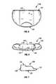
- FIG. 5is a bottom plan view of the club head shown in FIG. 1 .
- FIG. 6is a rear elevational view of the club head shown in FIG. 1 .
- FIG. 7is a right-side elevational view of the club head shown in FIG. 1 .
- FIG. 8is a top plan view of another embodiment of a golf club head constructed in accordance with the present invention.
- FIG. 9is front elevational view of the club head shown in FIG. 8 .
- FIG. 10is a bottom plan view of the club head shown in FIG. 8 .
- FIG. 11is a rear elevational view of the club head shown in FIG. 8 .
- FIG. 12is a right-side elevational view of the club head shown in FIG. 8 .
- FIG. 13is an exploded view of a club head of plural segments that collectively form a club head in accordance with the invention.
- FIG. 14is a back perspective view of a center segment of the club head.
- FIG. 15is a heel side view of the center segment of FIG. 14 .
- FIG. 16is a strike face perspective view of the center segment of FIG. 14 .
- FIG. 17is a sole perspective view of the center segment of FIG. 14 .
- FIG. 18shows a putter-type golf club having a club head constructed in accordance with the present invention.
- FIG. 19shows a perspective view of an iron-type club head.
- FIG. 20shows a perspective view of a wood-type club head.
- the golf club head described hereinhas certain features, and the following description and claims employ directional and reference words relating to those features.
- the ball striking surface or “strike face” of the club headwhich is intended to hit the golf ball, is located on the “front” of the club head.
- the “back” of the club headis the portion of the club head that is opposed to the front.
- the terms “top” and “bottom”assume that the club head is oriented as it would be if the golf club were held by a golfer in an at-rest position, i.e., the bottom of the club head would contact the ground when at rest.
- the top of the club headis referred to as the “crown” and the bottom of the club head is referred to herein as the “sole”.
- the “heel” of the club headis the portion of the club head nearest the golfer when the golfer holds the club in an at-rest position and the “toe” is the portion of the club head furthest from the golfer.
- the term “lateral”is used to refer to the dimension of the club head in the direction between the heel and toe. Thus, the heel of the club head is located laterally opposite the toe of the club head.
- FIGS. 1-7show various views of a putter-type golf club head 115 .
- a front, perspective view of the club head 110comprised of a body that attaches to a club shaft 115 .
- the club shaft 115is shown in FIG. 1 using phantom lines, and is not shown in FIGS. 2-7.
- the club shaft 115attaches to the club head 115 by mating with a borehole that is located on the club head 110 , such as through the use of a hosel that mates the shaft to the club head in a well-known manner.
- the club shaft 115can have bent configuration so that it defines a desired angle when the club is in an at-rest position.
- the club head 115may rather include a hosel that extends upwardly from the club head 115 and that connects to the club shaft 115 .
- the club head 110 and the club shaft 115collectively form a golf club 180 that can be used to strike a golf ball, such as is shown in FIG. 18 .
- An upper end of the club shaft 115typically will include a grip that a player grabs when swinging the golf club.
- FIG. 1shows the shaft 115 extending outwardly from the club head 110 at a particular angle. It should be appreciated that the shaft 115 can extend outwardly from the club head at a variety of different angles, as will be known to those of skill in the art.
- the club head 110has a crown 120 that forms a top surface of the club head 110 and a sole 125 (shown in FIGS. 4, 5 - 7 ) that forms a substantially flat, bottom surface of the club head 110 .
- the club head 110further has a flat strike face 130 for striking a golf ball.
- a back face 135is opposed to the strike face 130 and defines the rear periphery of the club head 110 .
- the club head 110 shown in FIGS. 1-7is a mallet-type club head so that the back face 135 has a rounded, convex contour with respect to the strike face 130 . It should be appreciated that the present invention is not limited to mallet-type club heads, but could also be employed in other types of club heads as described further below.
- the crown 120is rounded in both the heel and the toe of the club head 110 so that the heel and toe regions of the club head 110 smoothly merge into the crown 120 , thereby providing the club head 110 with a rounded, oblong shape when viewed from the front, as best shown in the front view of FIG. 4 .
- the crown 120has a multi-level, stepped-configuration such that a first region of the crown 120 is elevated a first distance from the club head's sole 125 and a second region of the crown 120 is elevated a second distance from the club head's sole 125 , as can be seen in the side view of FIG. 7 . It should be appreciated that the club head of the present invention is not limited to having a particular shape such as shown in the attached figures.
- a channel 150is located within the crown 120 of the club head 110 .
- the channel 150extends along a front-back direction on the crown 120 and preferably extends along the entire distance from the strike face 130 to the back face 135 of the club head 110 .
- the channel 150forms a front indentation 155 in an upper region of the strike face 130 at an edge where the strike face 130 merges with the crown 120 , as best shown in FIGS. 1 and 4.
- the front indentation 155 that is formed by the channel 150thereby affects the distance between the crown 120 and the sole 125 along at least a portion of the strike face 130 and also affects the total area of the strike face 130 .
- the channel 150also forms a rear indention 165 in an upper region of the back face at an edge where the back face 135 merges with the crown 120 , as best shown in FIGS. 2 and 6.
- a pair of opposed channel side walls 170delimit the lateral boundaries of the channel 150 .
- the channel side walls 170are preferably parallel to one another to thereby provide the channel 150 with a substantially uniform width in the lateral direction (i.e., heel-toe direction) of the club head 110 .
- the substantially uniform size of the channel 150facilitates its use during alignment of a golf swing, such as during putting, as described more fully below.
- a channel bottom wall 175forms the bottom boundary of the channel 150 .
- the bottom wall 175has a stepped configuration such that the bottom wall 175 has two or more tiers or levels. In this manner, the depth (i.e., along the direction from crown to sole) of the channel 150 varies moving from the front of the club head 110 toward the back of the club head 110 .
- the configuration of the bottom wall 175could differ.
- the bottom wall 175could be flat, thereby eliminating the multi-tiered steps in the bottom wall 175 .
- the bottom wall 175could also be sloped or contoured so that the depth of the channel 150 varies either continuously or non-continuously moving along a given direction.
- the club shaft 115mates with the club head 110 in a bore hole that is located in the channel 150 on the bottom wall 175 .
- the stepped configuration of the bottom wall 175 shown in FIG. 1is preferred in that it provides the club head 110 with a solid block of mass immediately behind the strike face 130 and a cavity behind the block of mass. This enhances feel for the player when the strike face 130 strikes a golf ball, such as during putting, and also provides the player with improved ball control when striking the ball with the golf club having the club head 110 .
- the presence of the channel 150 in the clubpermits an improved distribution of mass in the club head 110 in that the mass that would otherwise be located in the region of the channel 150 is freed up to be located in other regions of the club head 110 .
- the mass that would otherwise occupy the channel 150is preferably distributed in the toe and heel regions of the club head 110 so that the club head 110 has increased concentration of mass in the toe and heel.
- the channel 150forms an indentation 155 in the strike face 130 , the indentation being a result of mass that would occupy the region of the indentation if the channel 150 were not present.
- at least a portion of the mass that is freed up by the presence of the indentation 115is re-located in the sole region of the club head 110 .
- the mass distribution that is enabled by the presence of the channel 150results in an increased moment of inertia about the shaft 115 , thereby increasing the resistance of the club head to twisting when the club head strikes a golf ball.
- the golf clubis less likely to twist in the player's hands, thereby increasing the likelihood that the golf ball will be propelled in a desired direction.
- the weight distribution that results from the distribution of massmay also be enhanced through the use of certain materials in the club head 110 , as well as through the use of certain structures, as described more fully below.
- the channel 150also serves as an alignment aid for the player during swinging or putting of the golf club head 110 .
- the channel 150extends lengthwise in a direction from the front strike face 130 to the back face 135 of the club head 110 .
- the channel 150defines a longitudinal center axis 310 that is aligned with the direction that a golf ball would travel when the strike face 130 properly strikes a golf ball, such as during a putt.
- the playercan thus use the channel 150 in properly aligning the club head 110 during a swing.
- a proper putting motiontypically involves the player moving his or her arms in a pendulum-like motion so that the putter shaft defines an imaginary plane during this motion.
- the axis 310 of the channel 150would desirably be within the imaginary plane during the putting motion.
- the channel 150is preferably located on the crown of the club head 110 so that the player can view the channel 150 and use it as an alignment aid. However, the channel 150 could also be located on the sole, which would still allow for the mass-redistribution described above.
- the channel 150is preferably approximately 0.5 inches to 3.0 inches in width in the toe-heel direction. More preferably, the channel 150 is approximately 1.25 inches to 2.5 inches in width. Even more preferably, the channel is approximately 2 inches in width.
- the width of the channel 150is preferably larger than the diameter of a golf ball so that the player can frame the golf ball between the side walls 170 of the channel 150 when aligning the club head, such as prior to a putt.
- the channel 150preferably has a substantially uniform width moving from the front of the club head 110 to the back of the club head 110 so that the channel 150 provides a player with a clear indication of the direction and position of the central axis 310 when the club head 110 is viewed from the top.
- the width of the channel 150could also vary moving from the front to the back of the club head 110 .
- the width of the channel 150 at the front indentation 155may be larger than the width of the channel 150 at the back indentation 165 .
- the width of the channel 150 at the front indentation 155is larger than the diameter of a golf ball.
- FIGS. 8-12show another embodiment of the golf club head 110 , wherein the club head 110 is a blade-type putter head.
- the back face 135is substantially straight, rather than being convex, as in the mallet-type head shown in FIGS. 1-7.
- the blade-type putter head 110 of FIGS. 8-12also includes a channel 150 that is preferably located on the crown of the putter head 110 so that the channel 150 can function as an alignment aid.
- the channel 150forms an indentation 155 in the strike face 130 of the putter head 110 .
- the channel 150also forms an indentation 165 in the back face 135 of the putter head 110 .
- the club head 110may be manufactured of a variety of materials that are known to those of skill in the art.
- the club head 110may comprise a unitary piece of material, although in a preferred embodiment, the club head 110 comprises two or more segments of material that are joined together to collectively form the club head 110 .
- FIG. 13shows a putter-type club head 110 that is comprised of three segments, including a heel segment 1310 , a center segment 1315 , and a toe segment 1320 .
- FIG. 13shows the club head 110 in an exploded configuration with the segments 1310 , 1315 , 1320 separated from one another, although in use the segments are joined to collectively form a putter head 110 .
- the segments 1310 , 1315 , and 1320are not limited to having the particular shapes shown in FIG. 13 .
- the segments 1310 , 1315 , 1320may be shaped such that, when joined together, they would collectively form a club head having other club head shapes, such as the shapes shown in the embodiments of FIGS. 1-12.
- the club head 110can include more than two segments or could include only a single segment.
- the material of the center segment 1315is preferably different than the material of the heel segment 1310 and toe segment 1320 .
- the center segment 1315preferably comprises a non-metallic material, as described in more detail below, and the heel and toe segments 1310 , 1320 preferably each comprise a metallic material.
- the metallic material used in the heel and toe segments 1310 , 1320may be the same or different depending on the hitting characteristics desired.
- the term “metallic material”refers to an engineering material that includes at least one metal. Therefore, an organic material having metal would be considered a metallic material.
- the non-metallic material of the center segment 1315will be softer than the metallic material of the heel segment 1310 and toe segment 1320 . The center segment 1315 will thereby cushion and absorb the impact with the ball.
- the heel and toe segments 1310 , 1320preferably each comprise a metallic material including at least two metals.
- the metallic materialspreferably each have a final alloy density of at least 7 grams per cubic centimeter. In a more preferred version, the metallic materials each have a final alloy density of 7 to 13 grams per cubic centimeter. In a still more preferred version, the metallic materials each have a final alloy density of 9 to 11 grams per cubic centimeter. In a most preferred version of the invention, the metallic materials each have a final alloy density of approximately 10 grams per cubic centimeter.
- the heel and toe segments 1310 , 1320may also each comprise a metallic material wherein a first metal is dispersed in a second metal.
- the dispersion of the first metal in the second metalmay be achieved by powder metallurgy techniques wherein a powder of the first metal is blended with a powder of a second metal and the resulting powder metal blend is compacted and sintered at temperatures below the melting point of both metals.
- the first metalpreferably has a higher density than the second metal.
- the addition of a high density first metal to a lower density second metalallows the final alloy density of the metallic material of the heel and the toe segments 1310 , 1320 to be increased in precision increments.
- the first metalhas a density of at least 10 grams per cubic centimeter
- the second metalis selected from the group consisting of iron based alloys, nickel based alloys, and copper based alloys.
- a suitable first metalinclude tungsten, tantalum, niobium, and molybdenum.
- the metallic materialhas a final alloy density of at least 10 grams per cubic centimeter and the metallic material has a final alloy density at least 8 times greater than the density of the non-metallic material.
- the segments 1310 , 1315 , 1320may also be made of a fiber reinforced composite material.
- FIGS. 14-17show various views of the center segment 1315 , which preferably has a multipiece construction.
- the center segment 1315preferably comprises a shell 1400 that surrounds an inner core 1405 .
- the shell 1400is surrounded by an overmold 1410 that provides an outer shape to the center segment 1315 .
- the outer surface of the overmold 1410forms the outer surface of the club head 110 .
- a front face of the overmold 1410forms at least a portion of the strike face 130 of the club head.
- the front face of the overmold 1410is preferably substantially flat.
- the shape of the overmold 1410can be varied to provide the center segment 1315 and the club head 110 with any desired outer contour.
- the center segment 1310is located on the club head 110 in the region of the channel 150 such that the top surface of the center segment forms the bottom wall 175 of the channel 150 .
- the overmold 1410can be shaped so as to provide the bottom wall 175 of the channel with any desired shape.
- the overmold 1410is preferably manufactured of a pigmented, filled epoxy which is insert injection molded around a subassembly comprised of the core 1405 and shell 1400 .
- the overmold 1410has a preferred thickness of 0.015-0.100 inch.
- the properties of hardness, damping capacity, wear and weather resistance, and cosmetic appearanceare preferably the controlling properties for selection of the overmold material.
- the thickness of the overmold 1410can be varied to affect assembly vibration transmission when a golf ball is struck.
- the overmold 1410can also be manufactured of an epoxy alloyed with modifiers to increase damping capacity.
- the overmold 1410can be rubber filled, metal flake or particle, etc.
- the core 1405may have a shape that corresponds to the general shape of the body of the putter.
- the core 1405has a substantially flat bottom surface and a substantially flat front surface that is adjacent the strike face of the club head. In this manner, the properties of the material used to manufacture the core 1405 will influence the feel of the club head 110 when the strike face 130 hits a golf ball.
- the core 1405also has a contoured top surface that substantially conforms to the contour of the crown of the club head.
- the core 1405may be manufactured from graphite reinforced epoxy composite by pultrusion, compression molding, or resin transfer molding.
- the material of the core 1405has favorable mass and sound/vibration attenuation properties.
- the core 1405comprises either of a low cost bulk molded graphite epoxy material, a low cost bulk molded graphite-polyester material, a damping material, such as a polyurethane, a high damping viscoelastic material, such as rubber, or combinations thereof.
- the center segment 1315has no core.
- the shell 1400is preferably manufactured from a unidirectional graphite reinforced epoxy composite.
- the longitudinal stiffness of a materialis preferably a controlling property in selecting the material from which the shell 1400 is manufactured.
- the shape of the shell 1400generally conforms to the shape of the core 1405 .
- the shell 1400has a front face that is adjacent to the strike face of the club head. Thus, the properties of the shell 1400 will have some effect on the feel of the club head when the strike face impacts a golf ball.
- FIGS. 19 and 20show perspective views of iron and wood type club heads, respectively.
- the club headscan incorporate channels of the type described above in the context of the putter-type club head 110 . Those skilled in the art will understand how to achieve such incorporation, in view of the description above.
Landscapes
- Health & Medical Sciences (AREA)
- General Health & Medical Sciences (AREA)
- Physical Education & Sports Medicine (AREA)
- Life Sciences & Earth Sciences (AREA)
- Engineering & Computer Science (AREA)
- Wood Science & Technology (AREA)
- Golf Clubs (AREA)
Abstract
Description
Claims (9)
Priority Applications (1)
| Application Number | Priority Date | Filing Date | Title |
|---|---|---|---|
| US10/059,735US6692378B2 (en) | 2001-01-26 | 2002-01-28 | Golf club head with alignment channel |
Applications Claiming Priority (2)
| Application Number | Priority Date | Filing Date | Title |
|---|---|---|---|
| US26445901P | 2001-01-26 | 2001-01-26 | |
| US10/059,735US6692378B2 (en) | 2001-01-26 | 2002-01-28 | Golf club head with alignment channel |
Publications (2)
| Publication Number | Publication Date |
|---|---|
| US20020103039A1 US20020103039A1 (en) | 2002-08-01 |
| US6692378B2true US6692378B2 (en) | 2004-02-17 |
Family
ID=34922060
Family Applications (1)
| Application Number | Title | Priority Date | Filing Date |
|---|---|---|---|
| US10/059,735Expired - LifetimeUS6692378B2 (en) | 2001-01-26 | 2002-01-28 | Golf club head with alignment channel |
Country Status (1)
| Country | Link |
|---|---|
| US (1) | US6692378B2 (en) |
Cited By (35)
| Publication number | Priority date | Publication date | Assignee | Title |
|---|---|---|---|---|
| US20050020380A1 (en)* | 2003-07-23 | 2005-01-27 | Tetsuo Yamaguchi | Golf putter head |
| US20060148585A1 (en)* | 2005-01-04 | 2006-07-06 | Vinton Philip G | Golf putter heads |
| USD538364S1 (en) | 2006-02-27 | 2007-03-13 | Taylor Made Golf Company, Inc. | Golf club head |
| USD543598S1 (en) | 2006-09-11 | 2007-05-29 | Roger Cleveland Golf Company, Incorporated | Golf club head |
| US7264557B1 (en)* | 2007-01-10 | 2007-09-04 | Steven Grossbard | Golf putter with concave cylindrical or spherical striking surface |
| US20070243943A1 (en)* | 2006-04-14 | 2007-10-18 | Michael Takeshi Inouye | Golf putter head |
| US7294066B1 (en) | 2002-07-03 | 2007-11-13 | Richard Jr Joseph K | Golf putter head |
| USD564609S1 (en) | 2007-11-08 | 2008-03-18 | Nike, Inc. | Golf club head for a putter |
| USD564608S1 (en) | 2007-11-08 | 2008-03-18 | Nike, Inc. | Golf club head for a putter |
| US7396295B1 (en) | 2006-08-24 | 2008-07-08 | Taylor Made Golf Company, Inc. | Golf club head |
| US20080248894A1 (en)* | 2007-04-09 | 2008-10-09 | Mph Golf, Llc D.B.A. Gaim Golf | Golf Putter |
| US7485051B2 (en) | 2006-10-30 | 2009-02-03 | Richard Jr Joseph K | Golf putter |
| USD603007S1 (en) | 2009-08-05 | 2009-10-27 | Nike, Inc. | Golf club head for a putter |
| USD604782S1 (en) | 2009-08-05 | 2009-11-24 | Nike, Inc. | Golf club head for a putter |
| US7794333B2 (en) | 2008-02-21 | 2010-09-14 | Sri Sports Limited | Strike face insert |
| US20100298065A1 (en)* | 2009-05-19 | 2010-11-25 | Acushnet Company | Method of making golf clubs |
| US7993215B1 (en) | 2006-03-23 | 2011-08-09 | Gregory E. Summers | Producing golf clubs |
| US20120214609A1 (en)* | 2009-10-01 | 2012-08-23 | Lyle Dean Johnson | Whole mallet putter head |
| US8480504B2 (en) | 2010-06-01 | 2013-07-09 | Callaway Golf Company | Golf club head with alignment markings |
| USD697155S1 (en) | 2012-11-15 | 2014-01-07 | Taylor Made Golf Company, Inc. | Golf club head |
| US8758153B2 (en) | 2009-12-23 | 2014-06-24 | Taylor Made Golf Company, Inc. | Golf club head |
| US9330406B2 (en) | 2009-05-19 | 2016-05-03 | Cobra Golf Incorporated | Method and system for sales of golf equipment |
| US10343031B1 (en) | 2017-10-18 | 2019-07-09 | Cobra Golf Incorporated | Golf club head with openwork rib |
| US11020640B2 (en) | 2018-10-01 | 2021-06-01 | Karsten Manufacturing Corporation | Multi-component putter |
| US20220161108A1 (en)* | 2018-10-01 | 2022-05-26 | Karsten Manufacturing Corporation | Multi-component putter |
| US11458375B2 (en) | 2018-10-01 | 2022-10-04 | Karsten Manufacturing Corporation | Multi-component putter |
| US11511166B1 (en) | 2017-11-15 | 2022-11-29 | Cobra Golf Incorporated | Structured face for golf club head |
| US11850482B2 (en) | 2013-10-16 | 2023-12-26 | Sumitomo Rubber Industries, Ltd. | Putter-type golf club head |
| USD1026143S1 (en) | 2022-03-08 | 2024-05-07 | Karsten Manufacturing Corporation | Golf club head |
| US12145034B2 (en)* | 2013-10-16 | 2024-11-19 | Sumitomo Rubber Industries, Ltd. | Putter-type golf club head |
| US20240424356A1 (en)* | 2022-05-25 | 2024-12-26 | Taylor Made Golf Company, Inc. | Putter-type golf club head |
| US12233595B1 (en) | 2020-04-17 | 2025-02-25 | Cobra Golf Incorporated | Systems and methods for additive manufacturing of a golf club |
| US12285662B2 (en) | 2018-10-01 | 2025-04-29 | Karsten Manufacturing Corporation | Multi-component putter |
| USD1074887S1 (en) | 2023-04-14 | 2025-05-13 | Karsten Manufacturing Corporation | Golf club head |
| USD1077953S1 (en) | 2023-04-20 | 2025-06-03 | Karsten Manufacturing Corporation | Golf club head |
Families Citing this family (17)
| Publication number | Priority date | Publication date | Assignee | Title |
|---|---|---|---|---|
| US8096039B2 (en)* | 2003-08-11 | 2012-01-17 | Cobra Golf Incorporated | Golf club head with alignment system |
| US7351162B2 (en) | 2003-08-11 | 2008-04-01 | Acushnet Company | Golf club head with alignment system |
| US7918745B2 (en)* | 2003-08-11 | 2011-04-05 | Cobra Golf, Inc. | Golf club head with alignment system |
| US7396289B2 (en)* | 2003-08-11 | 2008-07-08 | Acushnet Company | Golf club head with alignment system |
| US7022030B2 (en)* | 2003-08-11 | 2006-04-04 | Acushnet Company | Golf club head |
| US7393285B2 (en) | 2004-01-23 | 2008-07-01 | Bernt Stellander | Putter with alignment means |
| US7125341B1 (en)* | 2004-05-04 | 2006-10-24 | Dsp Golf Concepts, Inc. | Golf club putter |
| WO2007035105A1 (en)* | 2005-09-23 | 2007-03-29 | Bernt Stellander | Putter with alignment means |
| US20070238544A1 (en)* | 2006-04-05 | 2007-10-11 | Joseph Jazwiec | Golf Putter with Alignment Head |
| USD564606S1 (en) | 2007-11-07 | 2008-03-18 | Nike, Inc. | Golf club head for a putter |
| US12036456B2 (en)* | 2015-05-16 | 2024-07-16 | David R Korn | Golf putter head for ensuring pure roll |
| US20170036078A1 (en)* | 2015-08-03 | 2017-02-09 | Karsten Manufacturing Corporation | Golf putter head with visual alignment aid and methods of manufacture |
| CN107854807B (en)* | 2017-11-27 | 2023-06-30 | 北京小米移动软件有限公司 | Running board assembly and running machine |
| CN107773913B (en) | 2017-11-27 | 2020-09-11 | 北京小米移动软件有限公司 | Running board assembly and treadmill |
| KR102811601B1 (en)* | 2019-03-06 | 2025-05-22 | 카스턴 매뉴팩츄어링 코오포레이숀 | Co-molded golf putter with integral interlocking features |
| USD1075984S1 (en)* | 2024-04-08 | 2025-05-20 | Putter Key Llc | Aiming key golf putter attachment |
| USD1075979S1 (en)* | 2024-10-03 | 2025-05-20 | Putter Key Llc | Aiming key golf putter attachment |
Citations (15)
| Publication number | Priority date | Publication date | Assignee | Title |
|---|---|---|---|---|
| US4655459A (en)* | 1985-12-04 | 1987-04-07 | Antonious A J | Golf club head |
| US4828265A (en)* | 1981-03-17 | 1989-05-09 | Antonious A J | Golf club head |
| US5308067A (en) | 1993-01-11 | 1994-05-03 | Cook Raymon W | Putter head |
| US5482281A (en)* | 1995-02-17 | 1996-01-09 | Karsten Mfg. Corp. | Golf putter head |
| US5575472A (en) | 1994-07-27 | 1996-11-19 | Odyssey Sports, Inc. | Golf putter head having face insert and method of forming the same |
| US5580058A (en) | 1995-06-07 | 1996-12-03 | Brian Edward Coughlin | Golf putter |
| US5655976A (en)* | 1995-12-18 | 1997-08-12 | Rife; Guerin | Golf club head with improved weight configuration |
| US5690562A (en) | 1996-09-03 | 1997-11-25 | Sturm; Ernst F. | Soft impact putter |
| US5842935A (en)* | 1997-07-17 | 1998-12-01 | Karsten Manufacturing Corporation | Golf putter head with low density insert |
| EP0891790A2 (en) | 1997-07-18 | 1999-01-20 | Never Compromise, Inc. | Multiple density golf club head and method of manufacturing |
| US5913731A (en) | 1997-11-10 | 1999-06-22 | Westerman; Clive B. | Golf putter |
| US5924939A (en)* | 1996-09-10 | 1999-07-20 | Cobra Golf Incorporated | Golf club head with a strike face having a first insert within a second insert |
| US5938543A (en) | 1997-07-18 | 1999-08-17 | Never Compromise, Inc. | Multiple density golf club head and method of manufacturing the same |
| US5951412A (en)* | 1996-01-25 | 1999-09-14 | Taylor Made Golf Company Co., Inc. | Golf club, particularly a putter |
| USD458657S1 (en)* | 2001-01-26 | 2002-06-11 | Never Compromise, Inc. | Golf club head |
- 2002
- 2002-01-28USUS10/059,735patent/US6692378B2/ennot_activeExpired - Lifetime
Patent Citations (15)
| Publication number | Priority date | Publication date | Assignee | Title |
|---|---|---|---|---|
| US4828265A (en)* | 1981-03-17 | 1989-05-09 | Antonious A J | Golf club head |
| US4655459A (en)* | 1985-12-04 | 1987-04-07 | Antonious A J | Golf club head |
| US5308067A (en) | 1993-01-11 | 1994-05-03 | Cook Raymon W | Putter head |
| US5575472A (en) | 1994-07-27 | 1996-11-19 | Odyssey Sports, Inc. | Golf putter head having face insert and method of forming the same |
| US5482281A (en)* | 1995-02-17 | 1996-01-09 | Karsten Mfg. Corp. | Golf putter head |
| US5580058A (en) | 1995-06-07 | 1996-12-03 | Brian Edward Coughlin | Golf putter |
| US5655976A (en)* | 1995-12-18 | 1997-08-12 | Rife; Guerin | Golf club head with improved weight configuration |
| US5951412A (en)* | 1996-01-25 | 1999-09-14 | Taylor Made Golf Company Co., Inc. | Golf club, particularly a putter |
| US5690562A (en) | 1996-09-03 | 1997-11-25 | Sturm; Ernst F. | Soft impact putter |
| US5924939A (en)* | 1996-09-10 | 1999-07-20 | Cobra Golf Incorporated | Golf club head with a strike face having a first insert within a second insert |
| US5842935A (en)* | 1997-07-17 | 1998-12-01 | Karsten Manufacturing Corporation | Golf putter head with low density insert |
| EP0891790A2 (en) | 1997-07-18 | 1999-01-20 | Never Compromise, Inc. | Multiple density golf club head and method of manufacturing |
| US5938543A (en) | 1997-07-18 | 1999-08-17 | Never Compromise, Inc. | Multiple density golf club head and method of manufacturing the same |
| US5913731A (en) | 1997-11-10 | 1999-06-22 | Westerman; Clive B. | Golf putter |
| USD458657S1 (en)* | 2001-01-26 | 2002-06-11 | Never Compromise, Inc. | Golf club head |
Cited By (50)
| Publication number | Priority date | Publication date | Assignee | Title |
|---|---|---|---|---|
| US7294066B1 (en) | 2002-07-03 | 2007-11-13 | Richard Jr Joseph K | Golf putter head |
| US20050020380A1 (en)* | 2003-07-23 | 2005-01-27 | Tetsuo Yamaguchi | Golf putter head |
| US7364514B2 (en)* | 2003-07-23 | 2008-04-29 | Sri Sports Limited | Golf putter head |
| US20060148585A1 (en)* | 2005-01-04 | 2006-07-06 | Vinton Philip G | Golf putter heads |
| US7491131B2 (en) | 2005-01-04 | 2009-02-17 | Vinton Philip G | Golf putter heads |
| USD538364S1 (en) | 2006-02-27 | 2007-03-13 | Taylor Made Golf Company, Inc. | Golf club head |
| US7993215B1 (en) | 2006-03-23 | 2011-08-09 | Gregory E. Summers | Producing golf clubs |
| US20070243943A1 (en)* | 2006-04-14 | 2007-10-18 | Michael Takeshi Inouye | Golf putter head |
| US20080200282A1 (en)* | 2006-08-24 | 2008-08-21 | Taylor Made Golf Company, Inc. | Golf club head |
| US7815520B2 (en) | 2006-08-24 | 2010-10-19 | Taylor Made Golf Company, Inc. | Golf club head |
| US7396295B1 (en) | 2006-08-24 | 2008-07-08 | Taylor Made Golf Company, Inc. | Golf club head |
| USD543598S1 (en) | 2006-09-11 | 2007-05-29 | Roger Cleveland Golf Company, Incorporated | Golf club head |
| US7485051B2 (en) | 2006-10-30 | 2009-02-03 | Richard Jr Joseph K | Golf putter |
| US20080167139A1 (en)* | 2007-01-10 | 2008-07-10 | Steven Grossbard | Golf putter with concave cylindrical or spherical striking surface |
| US7396292B1 (en) | 2007-01-10 | 2008-07-08 | Steven Grossbard | Golf putter with concave cylindrical or spherical striking surface |
| US7264557B1 (en)* | 2007-01-10 | 2007-09-04 | Steven Grossbard | Golf putter with concave cylindrical or spherical striking surface |
| US20080248894A1 (en)* | 2007-04-09 | 2008-10-09 | Mph Golf, Llc D.B.A. Gaim Golf | Golf Putter |
| US7601073B2 (en)* | 2007-04-09 | 2009-10-13 | Mph Golf, Llc | Golf putter |
| USD564608S1 (en) | 2007-11-08 | 2008-03-18 | Nike, Inc. | Golf club head for a putter |
| USD564609S1 (en) | 2007-11-08 | 2008-03-18 | Nike, Inc. | Golf club head for a putter |
| US7942757B2 (en) | 2008-02-21 | 2011-05-17 | Sri Sports Limited | Strike face insert |
| US20100292026A1 (en)* | 2008-02-21 | 2010-11-18 | Sri Sports Limited | Strike Face Insert |
| US7794333B2 (en) | 2008-02-21 | 2010-09-14 | Sri Sports Limited | Strike face insert |
| US8105181B2 (en) | 2008-02-21 | 2012-01-31 | Sri Sports Limited | Strike face insert |
| US8323122B2 (en)* | 2009-05-19 | 2012-12-04 | Cobra Golf Incorporated | Method of making golf clubs |
| US20100298065A1 (en)* | 2009-05-19 | 2010-11-25 | Acushnet Company | Method of making golf clubs |
| US12243085B1 (en) | 2009-05-19 | 2025-03-04 | Cobra Golf Incorporated | Method and system for sales of golf equipment |
| US8007373B2 (en)* | 2009-05-19 | 2011-08-30 | Cobra Golf, Inc. | Method of making golf clubs |
| US9330406B2 (en) | 2009-05-19 | 2016-05-03 | Cobra Golf Incorporated | Method and system for sales of golf equipment |
| USD603007S1 (en) | 2009-08-05 | 2009-10-27 | Nike, Inc. | Golf club head for a putter |
| USD604782S1 (en) | 2009-08-05 | 2009-11-24 | Nike, Inc. | Golf club head for a putter |
| US8777775B2 (en)* | 2009-10-01 | 2014-07-15 | Lyle D. Johnson | Whole mallet putter head |
| US20120214609A1 (en)* | 2009-10-01 | 2012-08-23 | Lyle Dean Johnson | Whole mallet putter head |
| US8758153B2 (en) | 2009-12-23 | 2014-06-24 | Taylor Made Golf Company, Inc. | Golf club head |
| US8480504B2 (en) | 2010-06-01 | 2013-07-09 | Callaway Golf Company | Golf club head with alignment markings |
| USD697155S1 (en) | 2012-11-15 | 2014-01-07 | Taylor Made Golf Company, Inc. | Golf club head |
| US11850482B2 (en) | 2013-10-16 | 2023-12-26 | Sumitomo Rubber Industries, Ltd. | Putter-type golf club head |
| US12145034B2 (en)* | 2013-10-16 | 2024-11-19 | Sumitomo Rubber Industries, Ltd. | Putter-type golf club head |
| US10343031B1 (en) | 2017-10-18 | 2019-07-09 | Cobra Golf Incorporated | Golf club head with openwork rib |
| US11511166B1 (en) | 2017-11-15 | 2022-11-29 | Cobra Golf Incorporated | Structured face for golf club head |
| US11813508B2 (en)* | 2018-10-01 | 2023-11-14 | Karsten Manufacturing Corporation | Multi-component putter |
| US11458375B2 (en) | 2018-10-01 | 2022-10-04 | Karsten Manufacturing Corporation | Multi-component putter |
| US20220161108A1 (en)* | 2018-10-01 | 2022-05-26 | Karsten Manufacturing Corporation | Multi-component putter |
| US11020640B2 (en) | 2018-10-01 | 2021-06-01 | Karsten Manufacturing Corporation | Multi-component putter |
| US12285662B2 (en) | 2018-10-01 | 2025-04-29 | Karsten Manufacturing Corporation | Multi-component putter |
| US12233595B1 (en) | 2020-04-17 | 2025-02-25 | Cobra Golf Incorporated | Systems and methods for additive manufacturing of a golf club |
| USD1026143S1 (en) | 2022-03-08 | 2024-05-07 | Karsten Manufacturing Corporation | Golf club head |
| US20240424356A1 (en)* | 2022-05-25 | 2024-12-26 | Taylor Made Golf Company, Inc. | Putter-type golf club head |
| USD1074887S1 (en) | 2023-04-14 | 2025-05-13 | Karsten Manufacturing Corporation | Golf club head |
| USD1077953S1 (en) | 2023-04-20 | 2025-06-03 | Karsten Manufacturing Corporation | Golf club head |
Also Published As
| Publication number | Publication date |
|---|---|
| US20020103039A1 (en) | 2002-08-01 |
Similar Documents
| Publication | Publication Date | Title |
|---|---|---|
| US6692378B2 (en) | Golf club head with alignment channel | |
| US6652390B2 (en) | Spread heel/toe weighted golf club | |
| US7803064B2 (en) | Golf club head with multiple undercuts | |
| US10046211B2 (en) | Golf clubs and golf club heads | |
| US9901792B2 (en) | Golf clubs and golf club heads | |
| US6123627A (en) | Golf club head with reinforcing outer support system having weight inserts | |
| US7198575B2 (en) | Golf club head | |
| US9956463B2 (en) | Golf clubs and golf club heads | |
| US8485920B2 (en) | Metal wood golf club head | |
| US7083525B2 (en) | Golf club head with insert | |
| US20180021637A1 (en) | Golf Club Head With Elevated Internal Weight | |
| KR102081048B1 (en) | Golf club head | |
| US9943733B2 (en) | Golf clubs and golf club heads | |
| US20060166758A1 (en) | Muscle-back, with insert, iron type golf club head | |
| US20120077615A1 (en) | Golf Putter | |
| EP2605839B1 (en) | Golf clubs and golf club heads | |
| JP2001204859A (en) | Golf club head | |
| US10821337B1 (en) | Golf club head with a hollow rail | |
| US20050054458A1 (en) | Tri-weight correlated set of iron type golf clubs | |
| US12343600B2 (en) | Golf club head with sole compliance zone | |
| US8632416B2 (en) | Golf clubs and golf club heads | |
| US6106410A (en) | Golf club iron head having lift-off sole | |
| US6428424B2 (en) | Golf putter | |
| JP7344862B2 (en) | Putter head with intermediate member | |
| JP2007125399A (en) | Golf club head with top line insert |
Legal Events
| Date | Code | Title | Description |
|---|---|---|---|
| AS | Assignment | Owner name:NEVER COMPROMISE, INC., CALIFORNIA Free format text:ASSIGNMENT OF ASSIGNORS INTEREST;ASSIGNORS:SHMOLDAS, ANDRE;POND, BRIAN;MCGEENEY, JIM;AND OTHERS;REEL/FRAME:012748/0219;SIGNING DATES FROM 20020211 TO 20020325 | |
| AS | Assignment | Owner name:ROGER CLEVELAND GOLF COMPANY, INC., CALIFORNIA Free format text:ASSIGNMENT OF ASSIGNORS INTEREST;ASSIGNOR:NEVER COMPROMISE, INC.;REEL/FRAME:014059/0572 Effective date:20030618 | |
| STCF | Information on status: patent grant | Free format text:PATENTED CASE | |
| FPAY | Fee payment | Year of fee payment:4 | |
| AS | Assignment | Owner name:SRI SPORTS LIMITED, JAPAN Free format text:ASSIGNMENT OF ASSIGNORS INTEREST;ASSIGNOR:ROGER CLEVELAND GOLF COMPANY, INC.;REEL/FRAME:024879/0984 Effective date:20100715 | |
| FPAY | Fee payment | Year of fee payment:8 | |
| FEPP | Fee payment procedure | Free format text:PAT HOLDER NO LONGER CLAIMS SMALL ENTITY STATUS, ENTITY STATUS SET TO UNDISCOUNTED (ORIGINAL EVENT CODE: STOL); ENTITY STATUS OF PATENT OWNER: LARGE ENTITY | |
| FPAY | Fee payment | Year of fee payment:12 |