US6691403B1 - Stripper tool for sheathed cable - Google Patents
Stripper tool for sheathed cableDownload PDFInfo
- Publication number
- US6691403B1 US6691403B1US09/185,493US18549398AUS6691403B1US 6691403 B1US6691403 B1US 6691403B1US 18549398 AUS18549398 AUS 18549398AUS 6691403 B1US6691403 B1US 6691403B1
- Authority
- US
- United States
- Prior art keywords
- sheath
- cable
- tool
- portions
- cutting
- Prior art date
- Legal status (The legal status is an assumption and is not a legal conclusion. Google has not performed a legal analysis and makes no representation as to the accuracy of the status listed.)
- Expired - Fee Related, expires
Links
- 238000009413insulationMethods0.000claimsabstractdescription9
- 238000010924continuous productionMethods0.000claimsabstractdescription6
- 239000011248coating agentSubstances0.000description2
- 238000000576coating methodMethods0.000description2
- 230000035939shockEffects0.000description2
- 238000005452bendingMethods0.000description1
- 238000003754machiningMethods0.000description1
- 239000002184metalSubstances0.000description1
- 238000000034methodMethods0.000description1
- 238000012856packingMethods0.000description1
Images


Classifications
- H—ELECTRICITY
- H02—GENERATION; CONVERSION OR DISTRIBUTION OF ELECTRIC POWER
- H02G—INSTALLATION OF ELECTRIC CABLES OR LINES, OR OF COMBINED OPTICAL AND ELECTRIC CABLES OR LINES
- H02G1/00—Methods or apparatus specially adapted for installing, maintaining, repairing or dismantling electric cables or lines
- H02G1/12—Methods or apparatus specially adapted for installing, maintaining, repairing or dismantling electric cables or lines for removing insulation or armouring from cables, e.g. from the end thereof
- H02G1/1202—Methods or apparatus specially adapted for installing, maintaining, repairing or dismantling electric cables or lines for removing insulation or armouring from cables, e.g. from the end thereof by cutting and withdrawing insulation
- H02G1/1204—Hand-held tools
- H02G1/1207—Hand-held tools the cutting element not rotating about the wire or cable
- H02G1/1209—Hand-held tools the cutting element not rotating about the wire or cable making a transverse cut
- H02G1/1214—Hand-held tools the cutting element not rotating about the wire or cable making a transverse cut not using wire or cable clamping means
- H—ELECTRICITY
- H02—GENERATION; CONVERSION OR DISTRIBUTION OF ELECTRIC POWER
- H02G—INSTALLATION OF ELECTRIC CABLES OR LINES, OR OF COMBINED OPTICAL AND ELECTRIC CABLES OR LINES
- H02G1/00—Methods or apparatus specially adapted for installing, maintaining, repairing or dismantling electric cables or lines
- H02G1/12—Methods or apparatus specially adapted for installing, maintaining, repairing or dismantling electric cables or lines for removing insulation or armouring from cables, e.g. from the end thereof
- H02G1/1295—Devices for splitting and dismantling flat cables
- Y—GENERAL TAGGING OF NEW TECHNOLOGICAL DEVELOPMENTS; GENERAL TAGGING OF CROSS-SECTIONAL TECHNOLOGIES SPANNING OVER SEVERAL SECTIONS OF THE IPC; TECHNICAL SUBJECTS COVERED BY FORMER USPC CROSS-REFERENCE ART COLLECTIONS [XRACs] AND DIGESTS
- Y10—TECHNICAL SUBJECTS COVERED BY FORMER USPC
- Y10T—TECHNICAL SUBJECTS COVERED BY FORMER US CLASSIFICATION
- Y10T29/00—Metal working
- Y10T29/49—Method of mechanical manufacture
- Y10T29/49002—Electrical device making
- Y10T29/49117—Conductor or circuit manufacturing
- Y10T29/49174—Assembling terminal to elongated conductor
- Y10T29/49181—Assembling terminal to elongated conductor by deforming
- Y10T29/49185—Assembling terminal to elongated conductor by deforming of terminal
- Y10T29/49192—Assembling terminal to elongated conductor by deforming of terminal with insulation removal
- Y—GENERAL TAGGING OF NEW TECHNOLOGICAL DEVELOPMENTS; GENERAL TAGGING OF CROSS-SECTIONAL TECHNOLOGIES SPANNING OVER SEVERAL SECTIONS OF THE IPC; TECHNICAL SUBJECTS COVERED BY FORMER USPC CROSS-REFERENCE ART COLLECTIONS [XRACs] AND DIGESTS
- Y10—TECHNICAL SUBJECTS COVERED BY FORMER USPC
- Y10T—TECHNICAL SUBJECTS COVERED BY FORMER US CLASSIFICATION
- Y10T29/00—Metal working
- Y10T29/51—Plural diverse manufacturing apparatus including means for metal shaping or assembling
- Y10T29/5136—Separate tool stations for selective or successive operation on work
- Y10T29/5137—Separate tool stations for selective or successive operation on work including assembling or disassembling station
- Y10T29/5139—Separate tool stations for selective or successive operation on work including assembling or disassembling station and means to sever work prior to disassembling
- Y10T29/514—Separate tool stations for selective or successive operation on work including assembling or disassembling station and means to sever work prior to disassembling comprising means to strip insulation from wire
- Y—GENERAL TAGGING OF NEW TECHNOLOGICAL DEVELOPMENTS; GENERAL TAGGING OF CROSS-SECTIONAL TECHNOLOGIES SPANNING OVER SEVERAL SECTIONS OF THE IPC; TECHNICAL SUBJECTS COVERED BY FORMER USPC CROSS-REFERENCE ART COLLECTIONS [XRACs] AND DIGESTS
- Y10—TECHNICAL SUBJECTS COVERED BY FORMER USPC
- Y10T—TECHNICAL SUBJECTS COVERED BY FORMER US CLASSIFICATION
- Y10T29/00—Metal working
- Y10T29/51—Plural diverse manufacturing apparatus including means for metal shaping or assembling
- Y10T29/5147—Plural diverse manufacturing apparatus including means for metal shaping or assembling including composite tool
- Y10T29/5148—Plural diverse manufacturing apparatus including means for metal shaping or assembling including composite tool including severing means
- Y10T29/515—Plural diverse manufacturing apparatus including means for metal shaping or assembling including composite tool including severing means to trim electric component
- Y10T29/5151—Means comprising hand-manipulatable implement
- Y—GENERAL TAGGING OF NEW TECHNOLOGICAL DEVELOPMENTS; GENERAL TAGGING OF CROSS-SECTIONAL TECHNOLOGIES SPANNING OVER SEVERAL SECTIONS OF THE IPC; TECHNICAL SUBJECTS COVERED BY FORMER USPC CROSS-REFERENCE ART COLLECTIONS [XRACs] AND DIGESTS
- Y10—TECHNICAL SUBJECTS COVERED BY FORMER USPC
- Y10T—TECHNICAL SUBJECTS COVERED BY FORMER US CLASSIFICATION
- Y10T29/00—Metal working
- Y10T29/51—Plural diverse manufacturing apparatus including means for metal shaping or assembling
- Y10T29/5186—Covering
- Y—GENERAL TAGGING OF NEW TECHNOLOGICAL DEVELOPMENTS; GENERAL TAGGING OF CROSS-SECTIONAL TECHNOLOGIES SPANNING OVER SEVERAL SECTIONS OF THE IPC; TECHNICAL SUBJECTS COVERED BY FORMER USPC CROSS-REFERENCE ART COLLECTIONS [XRACs] AND DIGESTS
- Y10—TECHNICAL SUBJECTS COVERED BY FORMER USPC
- Y10T—TECHNICAL SUBJECTS COVERED BY FORMER US CLASSIFICATION
- Y10T29/00—Metal working
- Y10T29/51—Plural diverse manufacturing apparatus including means for metal shaping or assembling
- Y10T29/5187—Wire working
- Y—GENERAL TAGGING OF NEW TECHNOLOGICAL DEVELOPMENTS; GENERAL TAGGING OF CROSS-SECTIONAL TECHNOLOGIES SPANNING OVER SEVERAL SECTIONS OF THE IPC; TECHNICAL SUBJECTS COVERED BY FORMER USPC CROSS-REFERENCE ART COLLECTIONS [XRACs] AND DIGESTS
- Y10—TECHNICAL SUBJECTS COVERED BY FORMER USPC
- Y10T—TECHNICAL SUBJECTS COVERED BY FORMER US CLASSIFICATION
- Y10T29/00—Metal working
- Y10T29/53—Means to assemble or disassemble
- Y10T29/5313—Means to assemble electrical device
- Y10T29/532—Conductor
- Y10T29/53209—Terminal or connector
- Y10T29/53213—Assembled to wire-type conductor
- Y10T29/53222—Means comprising hand-manipulatable implement
- Y—GENERAL TAGGING OF NEW TECHNOLOGICAL DEVELOPMENTS; GENERAL TAGGING OF CROSS-SECTIONAL TECHNOLOGIES SPANNING OVER SEVERAL SECTIONS OF THE IPC; TECHNICAL SUBJECTS COVERED BY FORMER USPC CROSS-REFERENCE ART COLLECTIONS [XRACs] AND DIGESTS
- Y10—TECHNICAL SUBJECTS COVERED BY FORMER USPC
- Y10T—TECHNICAL SUBJECTS COVERED BY FORMER US CLASSIFICATION
- Y10T29/00—Metal working
- Y10T29/53—Means to assemble or disassemble
- Y10T29/5313—Means to assemble electrical device
- Y10T29/53257—Means comprising hand-manipulatable implement
- Y—GENERAL TAGGING OF NEW TECHNOLOGICAL DEVELOPMENTS; GENERAL TAGGING OF CROSS-SECTIONAL TECHNOLOGIES SPANNING OVER SEVERAL SECTIONS OF THE IPC; TECHNICAL SUBJECTS COVERED BY FORMER USPC CROSS-REFERENCE ART COLLECTIONS [XRACs] AND DIGESTS
- Y10—TECHNICAL SUBJECTS COVERED BY FORMER USPC
- Y10T—TECHNICAL SUBJECTS COVERED BY FORMER US CLASSIFICATION
- Y10T29/00—Metal working
- Y10T29/53—Means to assemble or disassemble
- Y10T29/53274—Means to disassemble electrical device
- Y10T29/53283—Means comprising hand-manipulatable implement
- Y—GENERAL TAGGING OF NEW TECHNOLOGICAL DEVELOPMENTS; GENERAL TAGGING OF CROSS-SECTIONAL TECHNOLOGIES SPANNING OVER SEVERAL SECTIONS OF THE IPC; TECHNICAL SUBJECTS COVERED BY FORMER USPC CROSS-REFERENCE ART COLLECTIONS [XRACs] AND DIGESTS
- Y10—TECHNICAL SUBJECTS COVERED BY FORMER USPC
- Y10T—TECHNICAL SUBJECTS COVERED BY FORMER US CLASSIFICATION
- Y10T29/00—Metal working
- Y10T29/53—Means to assemble or disassemble
- Y10T29/53652—Tube and coextensive core
- Y—GENERAL TAGGING OF NEW TECHNOLOGICAL DEVELOPMENTS; GENERAL TAGGING OF CROSS-SECTIONAL TECHNOLOGIES SPANNING OVER SEVERAL SECTIONS OF THE IPC; TECHNICAL SUBJECTS COVERED BY FORMER USPC CROSS-REFERENCE ART COLLECTIONS [XRACs] AND DIGESTS
- Y10—TECHNICAL SUBJECTS COVERED BY FORMER USPC
- Y10T—TECHNICAL SUBJECTS COVERED BY FORMER US CLASSIFICATION
- Y10T29/00—Metal working
- Y10T29/53—Means to assemble or disassemble
- Y10T29/53657—Means to assemble or disassemble to apply or remove a resilient article [e.g., tube, sleeve, etc.]
- Y—GENERAL TAGGING OF NEW TECHNOLOGICAL DEVELOPMENTS; GENERAL TAGGING OF CROSS-SECTIONAL TECHNOLOGIES SPANNING OVER SEVERAL SECTIONS OF THE IPC; TECHNICAL SUBJECTS COVERED BY FORMER USPC CROSS-REFERENCE ART COLLECTIONS [XRACs] AND DIGESTS
- Y10—TECHNICAL SUBJECTS COVERED BY FORMER USPC
- Y10T—TECHNICAL SUBJECTS COVERED BY FORMER US CLASSIFICATION
- Y10T29/00—Metal working
- Y10T29/53—Means to assemble or disassemble
- Y10T29/53991—Work gripper, anvil, or element
Definitions
- the present inventionrelates to a method and tool for removing a non-metallic outer sheath from a cable, without damaging the inner wires.
- Brimmer in U.S. Pat. No. 5,669,132discloses a stripper tool to remove the outer sheath of an electrical cable having a pair of spaced apart covered electrical wires and an uncovered ground wire therebetween located inside the sheath (hereinafter referred to as “X/2 cable”). That stripper tool, however, is specifically designed to not cut the outer edges of the outer sheath.
- the useraccording to Brimmer, cuts the outer sheath except the outer edge, and then must remove the tool from the cable.
- the usergrasps the sheath, to be removed, and bends the uncut outer portion at least twice to break it. The user then pulls with his fingers the “broken” outer sheath from the cable to expose the electrical and ground wires.
- the Brimmer toolprovides an uncut portion on the sheath because Brimmer maintains the cable elongates itself when the tool cuts the outer sheath.
- Brimmerdesigned his tool to not cut the cable's outer edge, and inherently the electrical wire.
- None of the prior art patentsdescribe a hand-held stripper tool to cut the entire outer sheath of X/2 cable without cutting the electrical or ground wires. None of the prior art patents disclose a hand-held stripper tool wherein the user applies a force to the tool to cut the outer sheath of X/2 cable and then pushes on the tool to remove the cut outer sheath.
- the present inventionis a hand-held stripping tool.
- the toolis adapted for cutting an outer sheath of a first electrical cable. Inside the sheath is parallel spaced apart insulation covered wires and a core member containing an uncovered ground wire between the insulation covered wires.
- the sheathhas spaced apart curved sides conforming to the covered wires.
- the toolhas spaced apart first and second jaw members adapted to be pressed together.
- the jaw membershave cutting edges that receive a portion of the first cable along its length. The cutting edges define an opening configured to cut the sheath without significantly cutting the insulation on the wires or the unsheathed ground wire when the jaw members are pressed together to form the opening.
- the portion of the sheathis then removed in one continuous process.
- FIG. 1is a partial view of the first and second jaws specifically showing the cable positioned within the complete cutting opening.
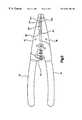
- FIG. 2is a perspective view of the stripper tool of the present invention.
- FIG. 3is a side view of the first and second jaws of the tool showing the cutting edges and the complete cutting opening.
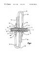
- FIG. 4is a cross-sectional view of FIG. 1 along the line 4 — 4 showing the knife blades of the cutting edges extending through the outer sheath.
- FIG. 5is an alternative embodiment of FIG. 2 .
- FIG. 1shows a preferred embodiment of a stripper tool 10 .
- the stripper tool 10is adapted to cut and remove an outer sheath 12 from a non-metallic sheathed cable 14 in one continuous process.
- the term “one continuous process”means the user does not release the force applied to the tool 10 until the cut outer sheath 12 is removed from the cable 14 .
- the cable 14 as shown in FIG. 1,has a non-metallic outer sheath 12 that encloses a pair of spaced apart electrical wires 16 and an uncovered ground wire 18 positioned between the electrical wires 16 .
- Packing 20is also located within the sheath 12 between the wires 16 and 18 and acts to keep the wires 16 and 18 spaced apart.
- Each electrical wire 16has an outer covering 22 to insulate the wires 16 and prevent electrical shorts and accidental electrical shock.
- Each wire 16forms an opposed side 12 A of the non-metallic sheath 12 .
- the electrical wires 16have a circular cross-section and are pressed against the opposed sides 12 A. As such, each opposed side 12 A forms an arcuate shape.
- the outer diameter D 1 of the outer covering 22is larger than the outer diameter D 2 of the uncovered ground wire 18 .
- the non-metallic sheath 12preferably has an essentially rectangular cross-section having a flat middle portion 12 B and opposed arcuate sides 12 A (FIG. 1 ).
- the positioning of the smaller outer diameter ground wire 18 between the larger diameter covered electrical wires 16allows the flat middle portion 12 B to be essentially flat and straight across.
- the larger diameter of the outer covering 22elevates the outer sheath 12 wherein the conventional position for the outer sheath 12 is spaced above and below the ground wire 18 . However, during cutting, the flat middle portion 12 B is pressed inward to contact the ground wire 18 (FIG. 1 ).
- the outer sheath 12is preferably constructed of a pliable plastic such as PVC that is easily cut by a sharp blade.
- the outer sheath 12is preferably 30 mills thick, thereby knife blades 24 and 26 (to be discussed in detail hereinafter) can easily cut through the outer sheath 12 without damaging the wires 16 and 18 .
- the cable 14is of the type commonly known as ROMEXTM sold by ELECTRICAL SUPPLIES.
- the stripper tool 10has a first lever member 30 and a second lever member 32 that attach to each other to form a pair of pliers.
- the first member 30 and second member 32provide a first handle 34 and a second handle 36 and a first jaw 38 and a second jaw 40 .
- the first member 30 and the second member 32are identical to enable the members to be interchangeable.
- the members 30 and 32have boss portions joined together at a pivot point 42 by a pivot nut 44 and a pivot bolt 46 .
- the pivotal connectionenables the levers 30 and 32 to pivot about pivot axis A-A of the tool 10 with respect to each other.
- the handles 34 and 36 and the jaws 38 and 40extend outward from the pivot point 42 perpendicular to the pivot axis A-A and parallel to the longitudinal axis B-B of the tool 10 (FIG. 3 ).
- the levers 30 and 32are connected in the conventional plier arrangement such that the second handle 36 is spaced above and parallel to the first handle 34 when the first jaw 38 is spaced above and parallel to the second jaw 40 (FIG. 2 ).
- the handles 34 and 36also have nubs 48 adjacent to the pivot point 42 that extend upward perpendicular to the axis B-B.
- a single coil spring 50is mounted between the nubs 48 and acts to bias the handles 34 and 36 .
- the jaws 38 and 40inherently, become spaced apart once the closing pressure on the handles 34 and 36 has been released.
- the nubs 48prevent the handles 34 and 36 from being pressed beyond the closed position. The nubs, thus, prevent the first and second members 30 and 32 from bending.
- the handles 34 and 36are preferably encased in an insulated, ergonomic outer coating 52 . That coating 52 enables the user (not shown) to better grip the tool 10 and protects the user against electrical shock in case the jaws 38 and 40 accidentally cut into a “hot” electrical wire (not shown).
- the ergonomic attributesare attained by the air gaps 55 .
- the jaws 38 and 40have proximal ends 38 C and 40 C and distal ends 38 D and 40 D with an outside surface 38 A and 40 A and an inside surface 38 B and 40 B, therebetween.
- the members 30 and 32are connected together such that the inside surface 38 B is adjacent the inside surface 40 B.
- the jaws 38 and 40are preferably angled inward toward the axis B-B so the proximal ends 38 C and 40 C, adjacent the pivot point 42 , are larger than the opposed distal ends 38 D and 40 D.
- the angled shape of the jaws 38 and 40enables the tool 10 to be used in tighter spaces.
- the first and second knife blades 24 and 26are located adjacent the proximal ends 38 C and 40 C near the pivot point 42 .
- the knife blades 24 and 26have two opposed arcuate end cutting parts 24 A and 26 A with a raised, preferably slightly arcuate or alternatively elongated, central or middle parts 24 B and 26 B therebetween.
- the knife blades 24 and 26have an elongated shape extending along the jaws 38 and 40 parallel to the axis B-B.
- the knife blades 24 and 26are tapered inward from outside surfaces 38 A and 40 A toward inside surfaces 38 B and 40 B.
- the cutting edges 24 C and 26 Care formed on the knife blades 24 and 26 at the inside surfaces 38 B and 40 B.
- the knife blades 24 and 26are tapered inwardly resulting in the cutting edge 24 C being adjacent and parallel to the cutting edge 26 C.
- the cutting edge 24 C and 26 Care sharp enough to easily cut the outer sheath 52 .
- the complete cutting opening 54( 54 A and 54 B) is shaped such that the center portion 54 B has a width less than that of the opposed arcuate ends 54 A.
- the width W 2 of the center portion 54 Bis only slightly smaller than the outer diameter D 2 of the sheath 52 over the ground wire 18 .
- the width W 1 of the opposed arcuate ends 54 Ais preferably slightly smaller than the outer diameter D 1 of the outer covering 22 .
- Each cutting edgeis shaped such that there are two end teeth respectively adjacent the end cutter parts 24 a and 26 a .
- the cutting edgeis also shaped such that there are two central teeth respectively defined at the junctures the end cutter parts and the middle cutter parts 24 b and 26 b.
- the length of the cutting opening 54is less than the width of the cable 14 between the opposed sides 12 A.
- the opening 54cuts the sheath 12 .
- the shape and width of the opposed ends 54 A and center portion 54 Bare such that when the jaws 38 and 40 are completely closed, the knife blades 24 C and 26 C sever the outer sheath 12 (FIG. 1 ).
- the widths W 1 and W 2 in the completely closed positionallow the knife blades 24 and 26 of the disclosed embodiment to not contact any of the three inner wires 16 and 18 or their respective coverings 22 .
- the cutting edges 24 C and 26 Care designed, under proper use, to not extend into the outer covering 22 or into the uncovered ground wire 18 (FIG. 4 ). Cutting into the outer covering 22 may cause an electrical short in the wires 16 that could lead to an electrical fire or cause electrical failure. Although, there is less cause for alarm if the ground wire 18 is nicked, completely severing the ground wire 18 could cause problems.
- the cutting opening 54accommodates at least one of the common sized ROMEXTM cable, i.e., 14/2, 12/2 or 10/2.
- the jaws 38 and 40are preferably constructed from metal with the cutting edges 24 and 26 and the knife edges 24 C and 26 C formed directly into the jaws 38 and 40 by a machining process.
- the jaws 38 and 40are provided with a plurality of recesses 60 in the distal ends 38 D and 40 D and spaced apart from the complete cutting opening 54 .
- the recesses 60are positioned to form a plurality of openings 62 when the first and second jaws 38 and 40 are moved together (FIG. 3 ).
- the plurality of openings 62are similar to conventional wire strippers that strip individually covered wires, conventional wire loop holes to twist wire 270°, and screw/bolt cutters.
- the plurality of recesses 60allow a variety of sized wires to be stripped, twisted and bolts/screws to be cut.
- the distal ends 38 D and 40 Dare curved toward the inside surface 38 B and 40 B, respectively.
- the curving of the distal ends 38 D and 40 Dforms a gap 64 between the jaws 38 and 40 (FIG. 3 ).
- the gap 64along with the curved distal ends 38 D and 40 D enable the tool 10 to be used to twist wires (not shown).
- the edges of the gap 64are dull in order to reduce the risk of damaging the wires during twisting.
- the distal ends 38 D and 40 Dalso form a conventional plier nose configuration.
- FIG. 5shows an alternate embodiment of the tool 10 .
- the alternate embodiment of tool 10is that it has supplementary cutting edges 124 and 126 .
- the supplementary cutting edges 124 and 126like the preferred cutting edges 24 and 26 , form a supplementary cutting opening 154 when the jaws 38 and 40 are pressed together.
- the supplementary cutting opening 154is spaced apart from the first cutting opening 54 toward the distal ends 38 D and 40 D.
- the supplementary cutting opening 154is identical to the first complete cutting opening 54 in shape, but has a different length and width.
- the supplementary cutting opening 154allows the tool 10 to be used to strip two different sizes of cable 14 .
- the tool 10has a locking mechanism 87 to secure the members 30 , 32 in place when tool 10 is not to be used.
- the semi-circular recesses 60can also be located on the other side of the opening 54 .
- the cable 14is positioned between the cutting edges 24 and 26 so the cable 14 is perpendicular to the axis B-B and the portion of the outer sheath 12 to be stripped extends outward from one side of the jaws 38 and 40 .
- the handles 34 and 36are then pressed together so the cutting edges 24 and 26 form the complete cutting opening 54 around the cable 14 .
- the opposed ends 54 Aare then adjacent the opposed sides 12 A and the narrower center portion 54 B is adjacent the flat middle portion 12 B.
- the handles 34 and 36are further pressed together until the knife blades 24 C and 26 C cut into the entire perimeter of the outer sheath 12 . Expressed another way, the sheath is circumferentially severed.
- the force needed to cut the sheath 12 with the stripper tool 10is easily accomplished by an adult using one hand (not shown).
- the knife blades 24 C and 26 Conly cut through the outer sheath 12 and do not cut into the outer covering 22 or into the uncovered ground wire 18 .
- the userpushes the tool 10 away from the cable 14 to remove the portion of the outer sheath 12 .
- the usercan release the pressure on the handles 34 and 36 and then use the plurality of circular recesses 60 to remove the outer covering 22 that are exposed after the outer sheath 12 is removed.
Landscapes
- Knives (AREA)
- Removal Of Insulation Or Armoring From Wires Or Cables (AREA)
Abstract
Description
Claims (11)
Priority Applications (4)
| Application Number | Priority Date | Filing Date | Title |
|---|---|---|---|
| US09/185,493US6691403B1 (en) | 1998-11-03 | 1998-11-03 | Stripper tool for sheathed cable |
| US09/876,465US6687991B2 (en) | 1998-11-03 | 2001-06-07 | Method for removing an outer sheath of an electrical cable |
| US10/775,832US7356915B2 (en) | 1998-11-03 | 2004-02-10 | Stripper tool for sheathed cable |
| US12/102,378US20080210058A1 (en) | 1998-11-03 | 2008-04-14 | Stripper Tool For Sheathed Cable |
Applications Claiming Priority (1)
| Application Number | Priority Date | Filing Date | Title |
|---|---|---|---|
| US09/185,493US6691403B1 (en) | 1998-11-03 | 1998-11-03 | Stripper tool for sheathed cable |
Related Child Applications (2)
| Application Number | Title | Priority Date | Filing Date |
|---|---|---|---|
| US09/876,465DivisionUS6687991B2 (en) | 1998-11-03 | 2001-06-07 | Method for removing an outer sheath of an electrical cable |
| US10/775,832ContinuationUS7356915B2 (en) | 1998-11-03 | 2004-02-10 | Stripper tool for sheathed cable |
Publications (1)
| Publication Number | Publication Date |
|---|---|
| US6691403B1true US6691403B1 (en) | 2004-02-17 |
Family
ID=22681211
Family Applications (4)
| Application Number | Title | Priority Date | Filing Date |
|---|---|---|---|
| US09/185,493Expired - Fee RelatedUS6691403B1 (en) | 1998-11-03 | 1998-11-03 | Stripper tool for sheathed cable |
| US09/876,465Expired - Fee RelatedUS6687991B2 (en) | 1998-11-03 | 2001-06-07 | Method for removing an outer sheath of an electrical cable |
| US10/775,832Expired - Fee RelatedUS7356915B2 (en) | 1998-11-03 | 2004-02-10 | Stripper tool for sheathed cable |
| US12/102,378AbandonedUS20080210058A1 (en) | 1998-11-03 | 2008-04-14 | Stripper Tool For Sheathed Cable |
Family Applications After (3)
| Application Number | Title | Priority Date | Filing Date |
|---|---|---|---|
| US09/876,465Expired - Fee RelatedUS6687991B2 (en) | 1998-11-03 | 2001-06-07 | Method for removing an outer sheath of an electrical cable |
| US10/775,832Expired - Fee RelatedUS7356915B2 (en) | 1998-11-03 | 2004-02-10 | Stripper tool for sheathed cable |
| US12/102,378AbandonedUS20080210058A1 (en) | 1998-11-03 | 2008-04-14 | Stripper Tool For Sheathed Cable |
Country Status (1)
| Country | Link |
|---|---|
| US (4) | US6691403B1 (en) |
Cited By (19)
| Publication number | Priority date | Publication date | Assignee | Title |
|---|---|---|---|---|
| US20050005738A1 (en)* | 1998-11-03 | 2005-01-13 | Murg Leonard R. | Stripper tool for sheathed cable |
| US20050188468A1 (en)* | 2003-11-04 | 2005-09-01 | Crawford Bruce A. | Multifunctional pliers |
| US20060059691A1 (en)* | 2004-09-22 | 2006-03-23 | Wiste Rodney J | Wire tool system and method |
| US7563124B1 (en)* | 2008-05-21 | 2009-07-21 | The United States Of America As Represented By The Secretary Of The Air Force | Harvesting power from low-voltage overhead power cables |
| US20100024604A1 (en)* | 2008-08-01 | 2010-02-04 | Nelson James M | Sheath and conductor strippers |
| US7802496B2 (en) | 2007-05-31 | 2010-09-28 | Pisczak Philip J | Stripper for round sheathed cable |
| US20110167642A1 (en)* | 2010-01-12 | 2011-07-14 | Steele Michael S | Pliers having wire strippers |
| USD653093S1 (en) | 2011-02-16 | 2012-01-31 | Greenlee Textron Inc. | Cable cutting and stripping tool |
| CN102801119A (en)* | 2012-08-03 | 2012-11-28 | 中铁四局集团电气化工程有限公司 | Signal-cable stripping forceps |
| US20130068646A1 (en)* | 2011-07-20 | 2013-03-21 | Michael Kirby | Hand tool |
| US8713805B2 (en) | 2010-07-27 | 2014-05-06 | Milwaukee Electric Tool Corporation | Hand cutting tool |
| US9415485B2 (en) | 2010-01-12 | 2016-08-16 | Milwaukee Electric Tool Corporation | Pliers having a sliding lock button |
| CN107462951A (en)* | 2015-04-15 | 2017-12-12 | 沈宇杰 | Self-bearing type butterfly leading in cable is clamped with stripping |
| CN107490826A (en)* | 2015-04-15 | 2017-12-19 | 戴丽芬 | A kind of self-bearing type butterfly leading in cable is clamped with stripping |
| CN107589485A (en)* | 2015-04-15 | 2018-01-16 | 沈宇杰 | A kind of butterfly leading in cable is clamped with stripping |
| CN107643563A (en)* | 2015-04-15 | 2018-01-30 | 沈宇杰 | A kind of butterfly leading in cable is clamped with stripping |
| CN110289577A (en)* | 2019-06-19 | 2019-09-27 | 国网湖北省电力有限公司宜昌供电公司 | Multi-purpose pliers for live wire stripping with foldable wires |
| US11554509B1 (en) | 2021-07-13 | 2023-01-17 | Lowell Dean Feil | Drip irrigation feeder pipe slicer tool and method of detaching barbed fittings and devices using the same |
| US20230100558A1 (en)* | 2020-02-11 | 2023-03-30 | Knipex-Werk C. Gustav Putsch Kg | Pliers-type cutting tool |
Families Citing this family (10)
| Publication number | Priority date | Publication date | Assignee | Title |
|---|---|---|---|---|
| USD490673S1 (en) | 2002-09-20 | 2004-06-01 | Alco Industries, Inc. | Cable stripping tool |
| US7887034B2 (en)* | 2005-08-01 | 2011-02-15 | Varian Semiconductor Equipment Associates, Inc. | Indirectly heated cathode clamp system and method |
| US8290810B2 (en)* | 2005-09-14 | 2012-10-16 | Jumptap, Inc. | Realtime surveying within mobile sponsored content |
| US20080109998A1 (en)* | 2006-11-10 | 2008-05-15 | Richard John Harold Graff | Safety handles for industrial cutting equipment |
| US9059573B2 (en)* | 2011-02-14 | 2015-06-16 | Textron Innovations Inc. | Cutting, stripping and crimping all-in-one tool |
| US9472927B2 (en) | 2014-04-22 | 2016-10-18 | Mark A. Satern | Wire stripping and cutting tool |
| USD827403S1 (en)* | 2017-04-28 | 2018-09-04 | Klein Tools, Inc. | Wire stripper |
| US10601206B2 (en)* | 2017-08-15 | 2020-03-24 | Stride Tool., Llc. | Apparatus and method for cutting and stripping an electrical cable |
| USD950336S1 (en) | 2019-09-27 | 2022-05-03 | Js Products, Inc. | Electrician's combination wire-working pliers |
| USD968182S1 (en) | 2020-02-05 | 2022-11-01 | Js Products, Inc. | Multi-functional electrician pliers |
Citations (13)
| Publication number | Priority date | Publication date | Assignee | Title |
|---|---|---|---|---|
| US1800317A (en)* | 1928-09-19 | 1931-04-14 | Warren E Ries | Pliers |
| US3871078A (en)* | 1973-03-12 | 1975-03-18 | Robert Ogle | Wire insulation stripper |
| US3947905A (en)* | 1975-03-12 | 1976-04-06 | Ted Neff | Multi-purpose electrical wiring tools |
| US4028756A (en)* | 1975-04-09 | 1977-06-14 | Thomas & Betts Corporation | Hand tool for working on electrical conductors |
| US4083105A (en)* | 1975-09-05 | 1978-04-11 | Ideal Industries, Inc. | Wire strippers |
| US4229849A (en)* | 1978-04-24 | 1980-10-28 | Minnesota Mining And Manufacturing Company | Hand crimp tool |
| US5323502A (en)* | 1993-03-25 | 1994-06-28 | Miller Christopher J | Wire stripping tool |
| US5669132A (en) | 1994-07-11 | 1997-09-23 | Brimmer; Roy F. | Stripper tool for non-metallic sheathed cable |
| US5711182A (en)* | 1996-09-09 | 1998-01-27 | Yang; Shyi-Dong | Crimping tool with wire stripping capability |
| US5724688A (en)* | 1994-08-02 | 1998-03-10 | Chen; Chin-Chuan | Multipurpose tool |
| US5732471A (en)* | 1996-11-14 | 1998-03-31 | Applied Power Inc. | Wire stripper with integral cable sheath cutter |
| US5826338A (en)* | 1995-01-17 | 1998-10-27 | Leatherman Tool Group, Inc. | Wire cutter structure for multipurpose tool |
| US6012357A (en)* | 1997-05-13 | 2000-01-11 | John; David W. | Insulation stripping tool |
Family Cites Families (10)
| Publication number | Priority date | Publication date | Assignee | Title |
|---|---|---|---|---|
| US1107684A (en)* | 1913-07-30 | 1914-08-18 | Livingston Mallory | Wire-clamp. |
| US3895426A (en)* | 1974-03-22 | 1975-07-22 | Cardinal Of Adrian | Wire stripping method and device |
| US4447949A (en)* | 1982-09-30 | 1984-05-15 | Kane Michael W | Wire stripper |
| US4607544A (en)* | 1985-05-06 | 1986-08-26 | Jewell Jr Robert M | Tool for cutting, stripping and connecting electric wire |
| ES295257Y (en)* | 1986-06-25 | 1987-08-16 | Diaz De Guerenu Aguirrebeitia Pablo | PERFECTED APPARATUS FOR STRIPPING ELECTRICAL AND SIMILAR CABLES |
| US4870876A (en)* | 1987-09-17 | 1989-10-03 | Ernesto Rodriquez | Pliers for inserting bushings |
| DE3844278A1 (en)* | 1988-03-17 | 1990-07-05 | Josef Krampe | STRIPPING TOOL FOR REMOVING THE INSULATION OF SINGLE OR MULTI-WIRE CABLES |
| US4912847A (en)* | 1988-12-05 | 1990-04-03 | Bradshaw William T | Cutting tool for `entx`-type plastic conduit |
| USD327826S (en)* | 1990-03-29 | 1992-07-14 | Ted Neff | Combined gripping, crimping, cutting and wire stripping tool |
| US6691403B1 (en)* | 1998-11-03 | 2004-02-17 | Stride Tool, Inc. | Stripper tool for sheathed cable |
- 1998
- 1998-11-03USUS09/185,493patent/US6691403B1/ennot_activeExpired - Fee Related
- 2001
- 2001-06-07USUS09/876,465patent/US6687991B2/ennot_activeExpired - Fee Related
- 2004
- 2004-02-10USUS10/775,832patent/US7356915B2/ennot_activeExpired - Fee Related
- 2008
- 2008-04-14USUS12/102,378patent/US20080210058A1/ennot_activeAbandoned
Patent Citations (13)
| Publication number | Priority date | Publication date | Assignee | Title |
|---|---|---|---|---|
| US1800317A (en)* | 1928-09-19 | 1931-04-14 | Warren E Ries | Pliers |
| US3871078A (en)* | 1973-03-12 | 1975-03-18 | Robert Ogle | Wire insulation stripper |
| US3947905A (en)* | 1975-03-12 | 1976-04-06 | Ted Neff | Multi-purpose electrical wiring tools |
| US4028756A (en)* | 1975-04-09 | 1977-06-14 | Thomas & Betts Corporation | Hand tool for working on electrical conductors |
| US4083105A (en)* | 1975-09-05 | 1978-04-11 | Ideal Industries, Inc. | Wire strippers |
| US4229849A (en)* | 1978-04-24 | 1980-10-28 | Minnesota Mining And Manufacturing Company | Hand crimp tool |
| US5323502A (en)* | 1993-03-25 | 1994-06-28 | Miller Christopher J | Wire stripping tool |
| US5669132A (en) | 1994-07-11 | 1997-09-23 | Brimmer; Roy F. | Stripper tool for non-metallic sheathed cable |
| US5724688A (en)* | 1994-08-02 | 1998-03-10 | Chen; Chin-Chuan | Multipurpose tool |
| US5826338A (en)* | 1995-01-17 | 1998-10-27 | Leatherman Tool Group, Inc. | Wire cutter structure for multipurpose tool |
| US5711182A (en)* | 1996-09-09 | 1998-01-27 | Yang; Shyi-Dong | Crimping tool with wire stripping capability |
| US5732471A (en)* | 1996-11-14 | 1998-03-31 | Applied Power Inc. | Wire stripper with integral cable sheath cutter |
| US6012357A (en)* | 1997-05-13 | 2000-01-11 | John; David W. | Insulation stripping tool |
Non-Patent Citations (4)
| Title |
|---|
| Ideal Industries, Inc. web site (http://www.idealindustries.com), NM Cable T(R)-Stripper Wire Stripper, Model No 46-249; Applicant became aware of product in or about Jul. 1998. |
| Ideal Industries, Inc. web site (http://www.idealindustries.com), NM Cable T(R)-Stripper Wire Stripper, Model No. 46-248; Applicant became aware of product in or about Jul. 1998. |
| Ideal Industries, Inc. web site (http://www.idealindustries.com), NM Cable T®-Stripper Wire Stripper, Model No 46-249; Applicant became aware of product in or about Jul. 1998. |
| Ideal Industries, Inc. web site (http://www.idealindustries.com), NM Cable T®-Stripper Wire Stripper, Model No. 46-248; Applicant became aware of product in or about Jul. 1998. |
Cited By (29)
| Publication number | Priority date | Publication date | Assignee | Title |
|---|---|---|---|---|
| US7356915B2 (en)* | 1998-11-03 | 2008-04-15 | Stride Tool Inc. | Stripper tool for sheathed cable |
| US20080210058A1 (en)* | 1998-11-03 | 2008-09-04 | Stride Tool Inc. | Stripper Tool For Sheathed Cable |
| US20050005738A1 (en)* | 1998-11-03 | 2005-01-13 | Murg Leonard R. | Stripper tool for sheathed cable |
| US20050188468A1 (en)* | 2003-11-04 | 2005-09-01 | Crawford Bruce A. | Multifunctional pliers |
| US20060059691A1 (en)* | 2004-09-22 | 2006-03-23 | Wiste Rodney J | Wire tool system and method |
| US7137204B2 (en) | 2004-09-22 | 2006-11-21 | Wiste Rodney J | Wire tool system and method |
| US7802496B2 (en) | 2007-05-31 | 2010-09-28 | Pisczak Philip J | Stripper for round sheathed cable |
| US7563124B1 (en)* | 2008-05-21 | 2009-07-21 | The United States Of America As Represented By The Secretary Of The Air Force | Harvesting power from low-voltage overhead power cables |
| US8151670B2 (en) | 2008-08-01 | 2012-04-10 | Nelson James M | Sheath and conductor strippers |
| US20100024604A1 (en)* | 2008-08-01 | 2010-02-04 | Nelson James M | Sheath and conductor strippers |
| US8667874B2 (en) | 2010-01-12 | 2014-03-11 | Milwaukee Electric Tool Corporation | Pliers having wire strippers |
| US20110167642A1 (en)* | 2010-01-12 | 2011-07-14 | Steele Michael S | Pliers having wire strippers |
| US9415485B2 (en) | 2010-01-12 | 2016-08-16 | Milwaukee Electric Tool Corporation | Pliers having a sliding lock button |
| US8713805B2 (en) | 2010-07-27 | 2014-05-06 | Milwaukee Electric Tool Corporation | Hand cutting tool |
| USD653093S1 (en) | 2011-02-16 | 2012-01-31 | Greenlee Textron Inc. | Cable cutting and stripping tool |
| US20130068646A1 (en)* | 2011-07-20 | 2013-03-21 | Michael Kirby | Hand tool |
| USD741681S1 (en) | 2011-07-20 | 2015-10-27 | Milwaukee Electric Tool Corporation | Hand tool |
| CN102801119A (en)* | 2012-08-03 | 2012-11-28 | 中铁四局集团电气化工程有限公司 | Signal-cable stripping forceps |
| CN102801119B (en)* | 2012-08-03 | 2015-08-19 | 中铁四局集团电气化工程有限公司 | Signal cable stripping clamps |
| CN107462951A (en)* | 2015-04-15 | 2017-12-12 | 沈宇杰 | Self-bearing type butterfly leading in cable is clamped with stripping |
| CN107490826A (en)* | 2015-04-15 | 2017-12-19 | 戴丽芬 | A kind of self-bearing type butterfly leading in cable is clamped with stripping |
| CN107589485A (en)* | 2015-04-15 | 2018-01-16 | 沈宇杰 | A kind of butterfly leading in cable is clamped with stripping |
| CN107643563A (en)* | 2015-04-15 | 2018-01-30 | 沈宇杰 | A kind of butterfly leading in cable is clamped with stripping |
| CN107490826B (en)* | 2015-04-15 | 2020-09-08 | 南京溧水高新创业投资管理有限公司 | Stripping pliers for self-supporting butterfly-shaped drop optical cable |
| CN107462951B (en)* | 2015-04-15 | 2020-12-15 | 义乌市优创知识产权运营有限公司 | Stripping pliers for self-supporting butterfly-shaped drop optical cable |
| CN110289577A (en)* | 2019-06-19 | 2019-09-27 | 国网湖北省电力有限公司宜昌供电公司 | Multi-purpose pliers for live wire stripping with foldable wires |
| US20230100558A1 (en)* | 2020-02-11 | 2023-03-30 | Knipex-Werk C. Gustav Putsch Kg | Pliers-type cutting tool |
| US12316080B2 (en)* | 2020-02-11 | 2025-05-27 | Knipex-Werk C. Gustav Putsch Kg | Pliers-type cutting tool |
| US11554509B1 (en) | 2021-07-13 | 2023-01-17 | Lowell Dean Feil | Drip irrigation feeder pipe slicer tool and method of detaching barbed fittings and devices using the same |
Also Published As
| Publication number | Publication date |
|---|---|
| US7356915B2 (en) | 2008-04-15 |
| US6687991B2 (en) | 2004-02-10 |
| US20020004984A1 (en) | 2002-01-17 |
| US20080210058A1 (en) | 2008-09-04 |
| US20050005738A1 (en) | 2005-01-13 |
Similar Documents
| Publication | Publication Date | Title |
|---|---|---|
| US6691403B1 (en) | Stripper tool for sheathed cable | |
| US5732471A (en) | Wire stripper with integral cable sheath cutter | |
| US5669132A (en) | Stripper tool for non-metallic sheathed cable | |
| US4722140A (en) | Knife system | |
| US5323502A (en) | Wire stripping tool | |
| US4953293A (en) | Electrician's utility knife | |
| US5062192A (en) | Cable stripping tool | |
| US6619158B2 (en) | Plier tool and method | |
| US3871078A (en) | Wire insulation stripper | |
| US20050188468A1 (en) | Multifunctional pliers | |
| US6588039B1 (en) | Plier tool and process | |
| US5009006A (en) | Cable stripping tool | |
| US20140345061A1 (en) | High voltage cable preparation tool | |
| US5414931A (en) | Universal stripping blade | |
| US6012357A (en) | Insulation stripping tool | |
| US3447172A (en) | Electrician's tool | |
| US20040118251A1 (en) | Wire stripper | |
| US4587731A (en) | Tool for cutting and stripping cable | |
| US7802496B2 (en) | Stripper for round sheathed cable | |
| JPS6133329B2 (en) | ||
| US6079105A (en) | Cable sheath stripping tool | |
| US4480509A (en) | Automatic wire stripper | |
| US7124786B1 (en) | Linesman pliers with wire splice twister | |
| US6067715A (en) | Wire and cable stripping tool | |
| US6502310B1 (en) | Cable insulation slitting tool |
Legal Events
| Date | Code | Title | Description |
|---|---|---|---|
| AS | Assignment | Owner name:STRIDE TOOL INC., NEW YORK Free format text:ASSIGNMENT OF ASSIGNORS INTEREST;ASSIGNOR:MURG, LEONARD R.;REEL/FRAME:009581/0476 Effective date:19981028 | |
| CC | Certificate of correction | ||
| CC | Certificate of correction | ||
| AS | Assignment | Owner name:NATIONAL CITY BUSINESS CREDIT, INC., OHIO Free format text:SECURITY AGREEMENT;ASSIGNOR:STRIDE TOOL, INC.;REEL/FRAME:018039/0673 Effective date:20060720 | |
| FPAY | Fee payment | Year of fee payment:4 | |
| AS | Assignment | Owner name:STRIDE TOOL INC., OHIO Free format text:RELEASE BY SECURED PARTY;ASSIGNOR:NATIONAL CITY BUSINESS CREDIT, INC.;REEL/FRAME:023056/0690 Effective date:20090723 | |
| AS | Assignment | Owner name:FIFTH THIRD BANK, OHIO Free format text:SECURITY AGREEMENT;ASSIGNOR:STRIDE TOOL INC.;REEL/FRAME:024990/0983 Effective date:20090723 | |
| FPAY | Fee payment | Year of fee payment:8 | |
| AS | Assignment | Owner name:STRIDE TOOL INC, OHIO Free format text:RELEASE BY SECURED PARTY;ASSIGNOR:FIFTH THIRD BANK;REEL/FRAME:027622/0268 Effective date:20111031 | |
| AS | Assignment | Owner name:ALOSTAR BANK OF COMMERCE, GEORGIA Free format text:SECURITY INTEREST;ASSIGNOR:STRIDE TOOL INC.;REEL/FRAME:035352/0863 Effective date:20150407 | |
| REMI | Maintenance fee reminder mailed | ||
| LAPS | Lapse for failure to pay maintenance fees | ||
| STCH | Information on status: patent discontinuation | Free format text:PATENT EXPIRED DUE TO NONPAYMENT OF MAINTENANCE FEES UNDER 37 CFR 1.362 | |
| FP | Lapsed due to failure to pay maintenance fee | Effective date:20160217 |