US6690854B2 - Optical wavelength division multiplexer - Google Patents
Optical wavelength division multiplexerDownload PDFInfo
- Publication number
- US6690854B2 US6690854B2US10/098,244US9824402AUS6690854B2US 6690854 B2US6690854 B2US 6690854B2US 9824402 AUS9824402 AUS 9824402AUS 6690854 B2US6690854 B2US 6690854B2
- Authority
- US
- United States
- Prior art keywords
- polarization
- output
- components
- polarization components
- optical
- Prior art date
- Legal status (The legal status is an assumption and is not a legal conclusion. Google has not performed a legal analysis and makes no representation as to the accuracy of the status listed.)
- Expired - Lifetime, expires
Links
- 230000003287optical effectEffects0.000titleclaimsabstractdescription72
- 230000010287polarizationEffects0.000claimsabstractdescription313
- 239000006185dispersionSubstances0.000claimsdescription29
- 230000001419dependent effectEffects0.000claims28
- 238000000034methodMethods0.000claims5
- 230000008878couplingEffects0.000claims1
- 238000010168coupling processMethods0.000claims1
- 238000005859coupling reactionMethods0.000claims1
- 239000013598vectorSubstances0.000description8
- 239000013078crystalSubstances0.000description7
- 238000000926separation methodMethods0.000description5
- 238000010586diagramMethods0.000description4
- 239000000463materialSubstances0.000description4
- 239000013307optical fiberSubstances0.000description4
- 238000006073displacement reactionMethods0.000description3
- 239000000835fiberSubstances0.000description3
- 239000004973liquid crystal related substanceSubstances0.000description3
- 230000001902propagating effectEffects0.000description3
- 210000004027cellAnatomy0.000description2
- 230000001143conditioned effectEffects0.000description2
- 210000002858crystal cellAnatomy0.000description2
- 238000012986modificationMethods0.000description2
- 230000004048modificationEffects0.000description2
- 208000022673Distal myopathy, Welander typeDiseases0.000description1
- 208000034384Welander type distal myopathyDiseases0.000description1
- 230000009471actionEffects0.000description1
- 230000008859changeEffects0.000description1
- 239000002223garnetSubstances0.000description1
- 230000005415magnetizationEffects0.000description1
- 238000012544monitoring processMethods0.000description1
- 239000010453quartzSubstances0.000description1
- VYPSYNLAJGMNEJ-UHFFFAOYSA-Nsilicon dioxideInorganic materialsO=[Si]=OVYPSYNLAJGMNEJ-UHFFFAOYSA-N0.000description1
- GWEVSGVZZGPLCZ-UHFFFAOYSA-Ntitanium dioxideInorganic materialsO=[Ti]=OGWEVSGVZZGPLCZ-UHFFFAOYSA-N0.000description1
- QWVYNEUUYROOSZ-UHFFFAOYSA-Ntrioxido(oxo)vanadium;yttrium(3+)Chemical compound[Y+3].[O-][V]([O-])([O-])=OQWVYNEUUYROOSZ-UHFFFAOYSA-N0.000description1
Images


Classifications
- G—PHYSICS
- G02—OPTICS
- G02B—OPTICAL ELEMENTS, SYSTEMS OR APPARATUS
- G02B6/00—Light guides; Structural details of arrangements comprising light guides and other optical elements, e.g. couplings
- G02B6/10—Light guides; Structural details of arrangements comprising light guides and other optical elements, e.g. couplings of the optical waveguide type
- G02B6/12—Light guides; Structural details of arrangements comprising light guides and other optical elements, e.g. couplings of the optical waveguide type of the integrated circuit kind
- G02B6/12007—Light guides; Structural details of arrangements comprising light guides and other optical elements, e.g. couplings of the optical waveguide type of the integrated circuit kind forming wavelength selective elements, e.g. multiplexer, demultiplexer
- G—PHYSICS
- G02—OPTICS
- G02B—OPTICAL ELEMENTS, SYSTEMS OR APPARATUS
- G02B6/00—Light guides; Structural details of arrangements comprising light guides and other optical elements, e.g. couplings
- G02B6/24—Coupling light guides
- G02B6/26—Optical coupling means
- G02B6/27—Optical coupling means with polarisation selective and adjusting means
- G02B6/2706—Optical coupling means with polarisation selective and adjusting means as bulk elements, i.e. free space arrangements external to a light guide, e.g. polarising beam splitters
- G02B6/2713—Optical coupling means with polarisation selective and adjusting means as bulk elements, i.e. free space arrangements external to a light guide, e.g. polarising beam splitters cascade of polarisation selective or adjusting operations
- G02B6/272—Optical coupling means with polarisation selective and adjusting means as bulk elements, i.e. free space arrangements external to a light guide, e.g. polarising beam splitters cascade of polarisation selective or adjusting operations comprising polarisation means for beam splitting and combining
- G—PHYSICS
- G02—OPTICS
- G02F—OPTICAL DEVICES OR ARRANGEMENTS FOR THE CONTROL OF LIGHT BY MODIFICATION OF THE OPTICAL PROPERTIES OF THE MEDIA OF THE ELEMENTS INVOLVED THEREIN; NON-LINEAR OPTICS; FREQUENCY-CHANGING OF LIGHT; OPTICAL LOGIC ELEMENTS; OPTICAL ANALOGUE/DIGITAL CONVERTERS
- G02F1/00—Devices or arrangements for the control of the intensity, colour, phase, polarisation or direction of light arriving from an independent light source, e.g. switching, gating or modulating; Non-linear optics
- G02F1/01—Devices or arrangements for the control of the intensity, colour, phase, polarisation or direction of light arriving from an independent light source, e.g. switching, gating or modulating; Non-linear optics for the control of the intensity, phase, polarisation or colour
- G02F1/09—Devices or arrangements for the control of the intensity, colour, phase, polarisation or direction of light arriving from an independent light source, e.g. switching, gating or modulating; Non-linear optics for the control of the intensity, phase, polarisation or colour based on magneto-optical elements, e.g. exhibiting Faraday effect
- G02F1/093—Devices or arrangements for the control of the intensity, colour, phase, polarisation or direction of light arriving from an independent light source, e.g. switching, gating or modulating; Non-linear optics for the control of the intensity, phase, polarisation or colour based on magneto-optical elements, e.g. exhibiting Faraday effect used as non-reciprocal devices, e.g. optical isolators, circulators
- G—PHYSICS
- G02—OPTICS
- G02F—OPTICAL DEVICES OR ARRANGEMENTS FOR THE CONTROL OF LIGHT BY MODIFICATION OF THE OPTICAL PROPERTIES OF THE MEDIA OF THE ELEMENTS INVOLVED THEREIN; NON-LINEAR OPTICS; FREQUENCY-CHANGING OF LIGHT; OPTICAL LOGIC ELEMENTS; OPTICAL ANALOGUE/DIGITAL CONVERTERS
- G02F1/00—Devices or arrangements for the control of the intensity, colour, phase, polarisation or direction of light arriving from an independent light source, e.g. switching, gating or modulating; Non-linear optics
- G02F1/29—Devices or arrangements for the control of the intensity, colour, phase, polarisation or direction of light arriving from an independent light source, e.g. switching, gating or modulating; Non-linear optics for the control of the position or the direction of light beams, i.e. deflection
- G02F1/31—Digital deflection, i.e. optical switching
- G—PHYSICS
- G02—OPTICS
- G02B—OPTICAL ELEMENTS, SYSTEMS OR APPARATUS
- G02B6/00—Light guides; Structural details of arrangements comprising light guides and other optical elements, e.g. couplings
- G02B6/24—Coupling light guides
- G02B6/26—Optical coupling means
- G02B6/27—Optical coupling means with polarisation selective and adjusting means
- G02B6/2726—Optical coupling means with polarisation selective and adjusting means in or on light guides, e.g. polarisation means assembled in a light guide
- G—PHYSICS
- G02—OPTICS
- G02B—OPTICAL ELEMENTS, SYSTEMS OR APPARATUS
- G02B6/00—Light guides; Structural details of arrangements comprising light guides and other optical elements, e.g. couplings
- G02B6/24—Coupling light guides
- G02B6/26—Optical coupling means
- G02B6/27—Optical coupling means with polarisation selective and adjusting means
- G02B6/2753—Optical coupling means with polarisation selective and adjusting means characterised by their function or use, i.e. of the complete device
- G02B6/2786—Reducing the polarisation degree, i.e. depolarisers, scramblers, unpolarised output
- G—PHYSICS
- G02—OPTICS
- G02B—OPTICAL ELEMENTS, SYSTEMS OR APPARATUS
- G02B6/00—Light guides; Structural details of arrangements comprising light guides and other optical elements, e.g. couplings
- G02B6/24—Coupling light guides
- G02B6/26—Optical coupling means
- G02B6/28—Optical coupling means having data bus means, i.e. plural waveguides interconnected and providing an inherently bidirectional system by mixing and splitting signals
- G02B6/293—Optical coupling means having data bus means, i.e. plural waveguides interconnected and providing an inherently bidirectional system by mixing and splitting signals with wavelength selective means
- G02B6/29302—Optical coupling means having data bus means, i.e. plural waveguides interconnected and providing an inherently bidirectional system by mixing and splitting signals with wavelength selective means based on birefringence or polarisation, e.g. wavelength dependent birefringence, polarisation interferometers
- G—PHYSICS
- G02—OPTICS
- G02B—OPTICAL ELEMENTS, SYSTEMS OR APPARATUS
- G02B6/00—Light guides; Structural details of arrangements comprising light guides and other optical elements, e.g. couplings
- G02B6/24—Coupling light guides
- G02B6/26—Optical coupling means
- G02B6/28—Optical coupling means having data bus means, i.e. plural waveguides interconnected and providing an inherently bidirectional system by mixing and splitting signals
- G02B6/293—Optical coupling means having data bus means, i.e. plural waveguides interconnected and providing an inherently bidirectional system by mixing and splitting signals with wavelength selective means
- G02B6/29304—Optical coupling means having data bus means, i.e. plural waveguides interconnected and providing an inherently bidirectional system by mixing and splitting signals with wavelength selective means operating by diffraction, e.g. grating
- G02B6/29305—Optical coupling means having data bus means, i.e. plural waveguides interconnected and providing an inherently bidirectional system by mixing and splitting signals with wavelength selective means operating by diffraction, e.g. grating as bulk element, i.e. free space arrangement external to a light guide
- G02B6/29311—Diffractive element operating in transmission
- G—PHYSICS
- G02—OPTICS
- G02F—OPTICAL DEVICES OR ARRANGEMENTS FOR THE CONTROL OF LIGHT BY MODIFICATION OF THE OPTICAL PROPERTIES OF THE MEDIA OF THE ELEMENTS INVOLVED THEREIN; NON-LINEAR OPTICS; FREQUENCY-CHANGING OF LIGHT; OPTICAL LOGIC ELEMENTS; OPTICAL ANALOGUE/DIGITAL CONVERTERS
- G02F1/00—Devices or arrangements for the control of the intensity, colour, phase, polarisation or direction of light arriving from an independent light source, e.g. switching, gating or modulating; Non-linear optics
- G02F1/01—Devices or arrangements for the control of the intensity, colour, phase, polarisation or direction of light arriving from an independent light source, e.g. switching, gating or modulating; Non-linear optics for the control of the intensity, phase, polarisation or colour
- G02F1/0136—Devices or arrangements for the control of the intensity, colour, phase, polarisation or direction of light arriving from an independent light source, e.g. switching, gating or modulating; Non-linear optics for the control of the intensity, phase, polarisation or colour for the control of polarisation, e.g. state of polarisation [SOP] control, polarisation scrambling, TE-TM mode conversion or separation
- G—PHYSICS
- G02—OPTICS
- G02F—OPTICAL DEVICES OR ARRANGEMENTS FOR THE CONTROL OF LIGHT BY MODIFICATION OF THE OPTICAL PROPERTIES OF THE MEDIA OF THE ELEMENTS INVOLVED THEREIN; NON-LINEAR OPTICS; FREQUENCY-CHANGING OF LIGHT; OPTICAL LOGIC ELEMENTS; OPTICAL ANALOGUE/DIGITAL CONVERTERS
- G02F1/00—Devices or arrangements for the control of the intensity, colour, phase, polarisation or direction of light arriving from an independent light source, e.g. switching, gating or modulating; Non-linear optics
- G02F1/01—Devices or arrangements for the control of the intensity, colour, phase, polarisation or direction of light arriving from an independent light source, e.g. switching, gating or modulating; Non-linear optics for the control of the intensity, phase, polarisation or colour
- G02F1/13—Devices or arrangements for the control of the intensity, colour, phase, polarisation or direction of light arriving from an independent light source, e.g. switching, gating or modulating; Non-linear optics for the control of the intensity, phase, polarisation or colour based on liquid crystals, e.g. single liquid crystal display cells
- G02F1/1326—Liquid crystal optical waveguides or liquid crystal cells specially adapted for gating or modulating between optical waveguides
- G—PHYSICS
- G02—OPTICS
- G02F—OPTICAL DEVICES OR ARRANGEMENTS FOR THE CONTROL OF LIGHT BY MODIFICATION OF THE OPTICAL PROPERTIES OF THE MEDIA OF THE ELEMENTS INVOLVED THEREIN; NON-LINEAR OPTICS; FREQUENCY-CHANGING OF LIGHT; OPTICAL LOGIC ELEMENTS; OPTICAL ANALOGUE/DIGITAL CONVERTERS
- G02F2201/00—Constructional arrangements not provided for in groups G02F1/00 - G02F7/00
- G02F2201/17—Multi-pass arrangements, i.e. arrangements to pass light a plurality of times through the same element, e.g. by using an enhancement cavity
- G—PHYSICS
- G02—OPTICS
- G02F—OPTICAL DEVICES OR ARRANGEMENTS FOR THE CONTROL OF LIGHT BY MODIFICATION OF THE OPTICAL PROPERTIES OF THE MEDIA OF THE ELEMENTS INVOLVED THEREIN; NON-LINEAR OPTICS; FREQUENCY-CHANGING OF LIGHT; OPTICAL LOGIC ELEMENTS; OPTICAL ANALOGUE/DIGITAL CONVERTERS
- G02F2203/00—Function characteristic
- G02F2203/58—Multi-wavelength, e.g. operation of the device at a plurality of wavelengths
- G02F2203/585—Add/drop devices
Definitions
- the present inventionrelates to a wavelength division multiplexer (WDM) and, more particularly, to an optical WDM that is a reflective system and is integrated.
- WDMwavelength division multiplexer
- Optical WDMsenable light of multiple wavelengths to be spatially dispersed such that each wavelength of light is spatially separated from every other wavelength of light.
- WDM devicestypically comprise two major functional portions. The first portion provides spatial demultiplexing (i.e., the dispersion) of the individual wavelengths through the use of a grating (e.g., an array waveguide grating, a filter array, etc.). The second portion then acts on one or more of the spatially dispersed wavelengths for purposes of, for example, attenuation, monitoring, compensation or switching.
- a gratinge.g., an array waveguide grating, a filter array, etc.
- a reflective systemIn a reflective system, these wavelengths are then sent back through the same dispersion element, thereby multiplexing them (i.e., combining the wavelengths) again onto one optical fiber.
- reflective WDM systemsIn fiber optic networks, reflective WDM systems are increasingly being used because of their lower complexity, smaller size and lower part count compared to transmissive WDM systems.
- the use of a reflective systemrequires the use of circulators to separate the incoming and outgoing signals. Circulators are often expensive and difficult to integrate into a small optical system.
- systems using polarization sensitive elementsare more complex and require another circulator-like separation stage to route a signal between the different ports.
- these types of systemstypically require precision alignment of several optical components, which is time consuming and expensive.
- an optical WDM devicethat is a reflective system., but that is smaller in size than known reflective WDM systems, that has a smaller part count than known reflective WDM systems, that does not require a circulator, and that does not require alignment of optical components.
- the present inventionprovides an integrated, reflective optical WDM device comprising optical components that are integrated together to provide a reflective WDM device that does not require any circulators, that has simplified alignment due to its integrated characteristics, and that is relatively low in cost.
- the WDM devicecomprises the integrated port separator, a dispersive element and a reflector.
- the integrated port separatorcomprises various optical components that spatially separate the polarization components of a light beam input through an input port of the integrated port separator.
- the spatially separated polarization componentsare output from the integrated port separator and impinge on the dispersive element, which spatially separates the wavelengths associated with the polarization components impinging thereon.
- the spatially separated wavelengthsthen impinge on the reflective element and are reflected with angles of polarization that depend on the state of the reflective element.
- the reflected polarization componentsmaintain their respective wavelengths when they are reflected. However, when they are reflected, they are directed along a path through the integrated port separator that depends on the angles of polarization of the reflected polarization components, which depends on the state of the reflective element.
- the reflective elementcomprises an array of liquid crystal display (LCD) pixels, each of which is individually controllable.
- LCDliquid crystal display
- the path of each polarization component through the integrated port separatordepends on the state of the LCD pixel upon which the polarization component impinges, which depends on the wavelength associated with each polarization component and the manner in which the dispersive element spatially separates the wavelengths to cause the corresponding polarization component to impinge on the reflective element.
- the optical devicecan be used for various purposes, such as, for example, for protection switching, in add/drop modules and in other applications where a polarization sensitive manipulation of wavelengths is needed or desired.
- FIG. 1is a schematic diagram of the optical device of the present invention in accordance with one embodiment.
- FIG. 2Ais a top view of the optical device of the present invention shown in FIG. 1 .
- FIG. 2Bis a side view of the optical device of the present invention shown in FIG. 1 .
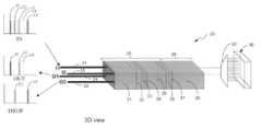
- FIG. 3is a perspective view of the optical device of the present invention configured in a particular manner using particular components and materials.
- FIG. 4is a polarization diagram demonstrating the manner in which the components shown in FIG. 3 perform particular polarization functions for wavelength division multiplexing.
- FIG. 5Ais a polarization diagram demonstrating another embodiment that utilizes a different configuration of components and the manner in which the components perform particular polarization functions to enable wavelength division multiplexing to be performed.
- FIG. 5Bis a top view of the WDM device of the present invention represented by FIG. 5 A.
- FIG. 5Cis a side view of the WDM device of the present invention represented by FIG. 5 A.
- FIG. 1is a schematic diagram of the optical WDM 20 of the present invention.
- the WDM 20preferably comprises four pigtailed ports, I 1 , O 1 , I 2 and O 2 , which are represented by numerals 21 , 22 , 23 and 24 , respectively, a directional stage 25 , a polarization stage 26 , a dispersion element 28 and a reflective element 30 having a plurality of states.
- the reflective element 30preferably is an array of liquid crystal cells, or pixels, each having a plurality of states that can be controllably selected.
- Each of the input ports 21 and 23is configured to receive light from an end of an optical fiber (not shown).
- Each of the output ports 22 and 24is configured to output light into an end of an optical fiber.
- Optics for relaying the light output between the fibers and the integrated WDM opticsmay include, for example, gradient-index (GRIN) lenses, micro-lenses or thermally expanded core (TEC) fibers.
- GRINgradient-index
- TECthermally expanded core
- the WDM device 20can be viewed as having a 2-stage separation in a tree-like structure.
- the stage represented by the dashed box 25the light entering input ports I 1 and I 2 is split into separate polarization beams that are then operated on by various optical components to provide them with a particular polarization.
- Each polarized beammay comprise a plurality of wavelengths of light. Since the direction of the light is used to define the positions of the light paths I 1 and O 1 and I 2 and O 2 , respectively, the stage 25 will be referred to herein as the directional stage.
- the path of the lightdepends on the polarization of the light on the incoming light paths I 1 and I 2 and on the outgoing light paths O 1 and O 2 . Therefore, stage 26 will be referred to herein as the polarization stage because it directs the light based on its polarization.
- the stage 26For the input beams I 1 and I 2 propagating through the stage 26 , the stage 26 provides the polarization components associated with each input beam with a particular polarization that causes light from I 1 and I 2 to be reflected along output paths O 1 and O 2 , respectively, when the reflective element 30 is not rotated, and that causes light from I 1 and I 2 to be reflected along output paths O 2 and O 1 , respectively, when the reflective element 30 is rotated.
- the polarization of the lightdepends on the state of the reflective element 30 , which determines how the light will be operated on by the polarization stage 26 when it is reflected by the reflective element 30 .
- the dispersion element 28receives the polarization components from the polarization stage 26 as they propagate towards the reflective element 30 and disperses (i.e., spatially separates) the wavelengths and their respective polarization components, thereby causing the polarization components to impinge on different pixels of the LC pixel array of the reflective element 30 .
- each pixelhas a plurality of states that can be selectively controlled.
- the polarization componentswill be output via the Ol path. Conversely, if the LC pixel upon which polarization components from the I 1 path impinge is rotated by 90°, the polarization component will be output via the O 2 path. Likewise, if the LC pixel upon which polarization components from the I 2 path impinge is not rotated, the polarization components will be output via the O 2 path. Conversely, if the pixel upon which a polarization components from the I 2 path impinge is rotated by 90°, the polarization components will be output via the Ol path.
- outputting the reflected polarization components along a particular pathis the equivalent of outputting the wavelengths associated with the reflected polarization components along the particular path.
- light input at I 1comprises certain wavelengths that need to be output via output path O 2 (i.e., dropped, or tapped off, at a certain location in a network) and other wavelengths need to continue in the forward direction (i.e., through output path O 2 )
- certain pixels of the reflective element 30would be rotated by 90° and other pixels would not be rotated.
- the wavelengths of light associated with the reflected polarization componentswould be combined by the dispersion element 28 and output via path O 2 .
- the wavelengths of light associated with the polarization components reflected by those pixelswould be combined by the dispersion element 28 and output via path O 1 .
- the dispersion element 28outputs light of different wavelengths so that it is output through the O 1 port or the O 2 port, regardless of whether the light is input through input port I 1 or input port I 2 .
- a polarization beamsplitter, a wollaston prism, or a walk-off crystalis used to provide the polarization components with one or more particular angles of polarization.
- the dispersive element 28preferably is a grating, such as an arrayed waveguide grating (AWG). The manner in which these components are implemented to accomplish these tasks will be described below in detail with reference to FIG. 4 .
- FIG. 2 A and FIG. 2BA top view and a side view of the integrated optical WDM 20 are shown in FIG. 2 A and FIG. 2B, respectively.
- the I 1 21 and O 1 22 light pathsremain in the same vertical planes over the course of those light paths through the WDM device 20 . Therefore, both light paths, although spatially separated, are represented by the single line labeled 21 , 22 .
- the I 2 23 and O 2 24 light pathsare in the same vertical planes with respect to the top view of FIG. 2A over the course of those light paths through the device 20 . Therefore, both of those light paths, although spatially separated, are also represented by the single line labeled 23 , 24 .
- the light paths I 1 21 and I 2 23are in the same transverse planes over the course of those light paths through the device 20 with respect to the side view. Therefore, both light paths, although spatially separated, are represented by the single line labeled 21 , 23 .
- the O 1 22 and O 2 24 light pathsare in the same transverse planes with respect to the side view of FIG. 3B over the course of those light paths through the device 20 . Therefore, both of those light paths, although spatially separated, are represented by the single line labeled 22 , 24 .
- FIG. 3illustrates a perspective view of the WDM 20 of the present invention in accordance with one embodiment, which includes a view of the complete, fully-integrated package, including the four pigtailed ports I 1 21 , I 2 23 , O 1 22 and O 2 24 .
- the directional stage 25is comprised of a first walk-off element (WO 1 ) 31 , a compensation element (Comp) 32 , a first Faraday rotator (F 1 ) 33 , a first half-waveplate (HWP 1 ) 34 , a second walk-off element (WO 2 ) 35 , a second Faraday rotator (F 2 ) 36 and a second half-waveplate (HWP 2 ) 37 .
- the polarization stage 26comprises a polarization combining and separating stage, which may be, for example, a third walk-off element (WO 3 ) 38 .
- FIG. 3also illustrates an example of the manner in which a group of wavelengths, ⁇ 1, ⁇ 2, ⁇ 3, ⁇ 4 and ⁇ 5 can be input from one input port, which is I 1 in this example, separated by the dispersion element 28 , and reflected by the reflective element 30 such that some ( ⁇ 1, ⁇ 3, ⁇ 4) of the wavelengths are combined by the dispersion element 28 onto the O 1 path and output through output port O 1 and some ( ⁇ 2 and ⁇ 5) of the wavelengths are combined by the dispersion element 28 onto the O 2 path and output through output port O 2 .
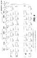
- FIG. 4shows the polarization of each of the components 31 - 38 for each of the light paths 21 - 24 .
- the blocks 21 A- 21 Ishow the polarization of each of the components 31 - 38 and LC cell 30 , respectively, along light path I 1 21 .
- the blocks 22 A- 22 Hshow the polarization of each of the components 31 - 38 , respectively, along light path O 1 22 .
- the blocks 24 A- 24 Hshow the polarization of each of the components 31 - 38 , respectively, along light path O 2 24 .
- the blocks 23 A- 23 Ishow the polarization of each of the components 31 - 38 and LC cell 30 , respectively, along light path I 2 23 .
- Light that enters the input ports I 1 21 and I 2 23will have a polarization vector that can be resolved into two orthogonal polarization components.
- light exiting output ports O 1 22 and O 2 24will have a polarization vector that corresponds to the combination of the two orthogonal polarization components.
- the polarization vector of the respective light signals entering a respective input portis initially resolved into two separate orthogonal polarization components, walked-off in particular directions, and rotated in particular manners so that the light signals from these ports of various wavelengths that pass through the dispersion element 28 and impinge on the reflective element 30 will be reflected, combined and output through either output port O 1 22 , output port O 2 24 , or partially through each of the output ports O 1 22 and O 2 24 .
- the arrangementis such that none, or substantially none, of the light from one of the input ports I 1 or I 2 is reflected back into one of the input ports.
- the polarization components of each of the respective polarization vectors of each of the respective signalswill be combined before exiting the output ports O 1 and/or O 2 , as indicated by the plus signs in blocks 22 A and 24 A. Therefore, whereas respective input paths of the directional stage 25 separate the respective polarization vectors into separate polarization components and operate on them in a particular manner, the output paths of the directional stage 25 operate on the respective reflected, separated polarization components in a particular manner and combine the respective polarization components into respective polarization vectors.
- the waveplates 31 , 34 and 37may be made of quartz, which is a material typically used to produce waveplates.
- the walk-off elements 31 , 35 and 38may be made of yttrium vanadate or of a rutile material, for example.
- a walk-off crystalhas a polarization direction defined by its crystal structure.
- the Faraday rotators 33 and 36may be made of garnet, for example. Faraday rotators rotate light polarization through the application of a magnetic field.
- the Faraday rotatorscan be “latched” Faraday rotators. Latched Faraday rotators will continue to rotate light through magnetization even after the magnetic field is no longer being applied to the latched Faraday rotator.
- a magnetmay be embedded in the integrated WDM device 20 adjacent to or in close proximity to the Faraday rotator to enable the necessary magnetic field to be generated.
- the polarization vector of the light signal entering port I 1 from an optical fiberinitially is not separated into separate orthogonal components, as indicated by the small cross in the block 21 A. However, after the incoming light signal passes through WO 1 31 , the horizontal polarization component of the light signal is separated and displaced from the vertical polarization component in the walk-off direction, as indicated by block 21 B.
- WO 1 31operates only on the polarization component of the light that is parallel to the walk-off direction of the WO 1 31 (i.e., only on the horizontal polarization component, which is parallel to the walk-off direction indicated by the horizontal arrow in block 31 ). This separates and displaces the horizontally polarized component from the vertically polarized component.
- light having a polarization that is parallel to the walk-off direction of WO 1 31is separated into a beam by WO 1 31 that has the same orientation as WO 1 31 .
- Light having a polarization that is not parallel to the walk-off direction of WO 1 31is not displaced, but forms a beam that is coincident with the original light beam and that has a polarization that is orthogonal to the polarization of the displaced beam.
- These beamsthen pass through the compensation element 32 , which does not change the polarization of the beams, but simply compensates for any light path length differences caused by the walk-off displacement.
- the lightthen passes through a first Faraday rotator F 1 33 , which changes the direction of polarization of each of the beams by 45°, as indicated by the lines in block 21 D.
- the lightthen passes through a first half waveplate HWP 1 34 , which separately rotates the polarizations of each of the beams such that they both have a horizontal polarization, as indicated by block 21 E.
- the dashed lines in the HWP 1 component 34indicate that each portion of the component operates on the polarized beams differently, which is also apparent from the notation in blocks 21 E, 22 D, 23 E and 24 D.
- the polarization componentsare horizontal, they will not be affected as they pass through the second walk-off element WO 2 35 , which has a vertical walk-off direction, as indicated by the vertical double-ended arrow in block 35 .
- the light beams traveling along the I 1 light path 21then pass through the second Faraday rotator F 2 36 , which rotates the polarizations of the beams by 45°, as shown in block 21 G.
- F 2 36operates on light traveling along light paths O 1 and O 2 to rotate the polarizations such that they are vertical, as indicated by the lines in blocks 22 G, 22 F, 24 G and 24 F, which enables the O 1 and O 2 light path polarizations to be operated on by WO 2 35 in order to direct those light paths in the direction indicated in the directional stage 25 shown in the side view of FIG. 3 B.
- the light beams traveling along I 1then pass through HWP 2 37 , which rotates the polarizations of both beams into horizontal polarizations, as indicated by the lines in 21 H.
- the light beams traveling along I 1then passes through the polarization stage 26 , which corresponds, in this example, to the WO 3 block 38 .
- the WO 3 38changes the direction of the light beams such that the beams corresponding to light path I 1 are displaced horizontally in the manner indicated in the polarization stage 26 shown in the top view of FIG. 2 A.
- the horizontal displacementis indicated by the horizontal lines in block 21 H and their movement from the left, upper corner of that block to the right, upper corner of block 21 I.
- the light beams corresponding to light path I 1 having the polarization shown in block 21 Ithen pass through the dispersion element 28 , which spatially separates all of the wavelengths in the light beams.
- the polarization components of the light beamsimpinge on various pixels of the reflective element 30 , depending on the wavelength associated with the polarization components.
- the pixel that the polarization components impinge onis not rotated, the light beams corresponding to light path I 1 are reflected by that pixel and combined by the dispersion element such that they pass through WO 3 38 , which displaces the beams horizontally.
- This horizontal shift in polarizationis indicated by the horizontal shift in the position of the lines in block 21 I to the positions shown in block 22 H. Therefore, in this case, the reflected light enters the O 1 light path and is operated on by the elements of the directional stage 25 in the manner indicated by the lines in blocks 22 H- 22 A.
- the O 1 light pathtracks the I 1 light path, but is below it in the transverse planes due to WO 2 , as shown in the top view of FIG. 2 A and as indicated by the shift of the polarization components in the vertical direction in correspondence with the lines in blocks 22 F and 22 E.
- the WO 1 31combines the polarization components of the light traveling on light paths O 1 and O 2 , respectively, just before they are output through output ports O 1 and O 2 , respectively. This is indicated by the lines in blocks 22 B and 22 A and 24 B and 24 A.
- the different location of the cross in block 23 A compared to the location of the cross in block 21 Aindicates the horizontal separation of the beams on input light paths I 1 and I 2 , which is evident from the top view of FIG. 2 A.
- the horizontal polarization componentis separated from the vertical polarization component when the light passes through WO 1 31 , as indicated by the polarization notation lines in block 23 B.
- the polarization changes indicated by the polarization notation in blocks 23 B- 23 G for the I 2 light pathare essentially the same as those indicated by blocks 21 B- 21 G, respectively, for the I 1 path.
- HWP 2 37operates on the polarization components of light on light paths I 2 and O 2 in a manner different from the manner in which it operates on the polarization components of light on light paths I 1 and O 1 .
- HWP 2 37rotates the polarization components of light on light path I 1 so that they are horizontal, whereas it rotates the polarization components of light on light path I 2 so that they are vertical, as indicated by blocks 21 H and 23 H, respectively.
- the vertical polarization componentsare not even shifted due to the fact that WO 3 38 is a horizontal walk-off crystal. With these polarizations, the reflected I 1 light can only enter light path O 1 and the reflected I 2 light can only enter light path O 2 . The reflected light then passes through the directional stage 25 along the respective output light paths and exits the integrated optical WDM 20 through the respective output ports.
- the corresponding LC pixel of the reflective element 30When the corresponding LC pixel of the reflective element 30 is fully rotated (i.e., rotated by 90°), the light on light path I 1 having the polarization indicated by block 21 I is dispersed by the dispersion element 28 and reflected by the rotated pixel with a vertical polarization such as that shown in block 24 H. This light then passes through WO 3 38 unaffected and thus is conditioned only to propagate along the O 2 light path.
- the polarization componentshave wavelengths associated with them. Therefore, directing polarization components from light path I 1 onto light path O 2 is the equivalent of directing the wavelengths associated with those polarization components from light path I 1 onto light path O 2 .
- wavelengthscan be selectively separated out by the WDM of the present invention. This allows wavelengths to be selectively separated out and dropped (e.g., switched from I 1 to O 2 ) or added (e.g., all wavelengths of light from I 1 go to O 1 and at least some wavelengths of light from I 2 go to O 1 ).
- the WDM of the present inventioncan serve many other purposes.
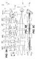
- FIG. 5Aillustrates a configuration of various optical components and the manner in which they operate on the polarization components of light to perform the WDM functions.
- the conceptsare generally the same as those described above with reference to FIG. 4, but the configuration of the WDM is different from the configuration of FIG. 4 .
- FIG. 5Billustrates a top view of the components shown in FIG. 5 A and the manner in which the polarization components of input light and reflected light propagate through the optical WDM device.
- FIG. 5Cillustrates a side view of the components shown in FIG. 5 A and the manner in which the polarization components of input light and reflected light propagate through the optical WDM device.
- the optical WDM deviceis comprised of a walk-off (W/OFF) element 41 , a half waveplate (HWP) element 42 , a walk-on (W/ON) element 43 , a Faraday rotator 44 , another HWP element 45 , a walk-on (W/ON) element 46 , a dispersion element 47 and a reflective element 50 , which preferably is an array of selectively controllable LC pixels, as in the embodiment of FIG. 4 .
- the block 51illustrates four light beams, each of which has two polarization components that are orthogonally combined.
- Light beams 51 and 52correspond to the O 1 and I 1 light paths, respectively, and light beams 53 and 54 correspond to the I 2 and O 2 light paths, respectively.
- the W/OFF element 41displaces the horizontal polarization component 52 A of beam 52 , which corresponds to the I 1 input light, from its vertical component 52 B.
- the W/OFF element 41displaces the horizontal polarization component 53 A of beam 53 , which corresponds to the I 2 input light, from its vertical component 53 B.
- the W/OFF element 41combines the horizontal component 54 A of beam 54 , which corresponds to the output light path O 2 , with its vertical component 54 B.
- the W/OFF element 41combines the horizontal component 51 A of beam 51 , which corresponds to the output light path O 1 , with its vertical component 51 B. This separating and combining of the polarization components can be seen in block 41 of FIG. 5 C.
- the HWP 42only operates on the separated polarization components in the right side of the box, namely, polarization components 51 A, 52 B, 53 A and 54 B. This can also be seen from block 42 in FIG. 5C in that only half of the polarization components propagate through the HWP 42 .
- HWP 42applies a clockwise 90° rotation, as indicated by the horizontal orientations of the dashes in the following box.
- the polarization components 51 A and 53 Aare also rotated clockwise by 90° as they pass through the HWP 42 propagating in the direction of the W/OFF element 41 , as shown in the box proceeding the HWP 42 .
- the W/OFF element 41then orthogonally combines polarization components 51 A and B and 54 A and B to form two beams, each having two polarization components that are orthogonal to each other.
- the input lightpasses through W/ON element 43 .
- the input light polarization components 53 A and Bwhich are now vertically polarized, are shifted upwards. This can be seen from the vertical incline of the I 2 input shown in block 43 FIG. 5 B.
- the input light polarization components 52 A and B of the I 1 inputremain horizontally polarized and are not affected as they propagate through the W/ON element 43 , as indicated by the straight I 1 line passing through block 43 in FIG. 6 B.
- the W/ON element 43shifts the polarization components 51 A and B of the output light O 1 down, but leaves them vertically polarized.
- the Faraday rotator 44rotates the horizontally and vertically polarized input light polarization components 52 A and B and 53 A and B, respectively, by 45°.
- the HWP 45then rotates the input light polarization components 53 A and B and 52 A and B clockwise by 45° such that the input light polarization components 52 A and B are vertically polarized and the input light polarization components 53 A and B are horizontally polarized.
- the W/ON element 46then shifts the vertically polarized input light polarization components 52 A and 52 B down such that they are spatially coincident with and orthogonal to the horizontally polarized input light polarization components 53 A and B, respectively.
- the downward shift of the vertically polarized input light polarization components 52 A and 52 Bis indicated by the downward incline in block 46 of FIG. 5B with respect to the direction of propagation of the input light.
- the vertically-polarized reflected light polarization components 51 A and Bare shifted down to separate them from the horizontally-polarized output light polarization components 54 A and B.
- the spatially-separated vertically polarized input light polarization components 52 A and B of input light I 1will be reflected by the pixel with the same polarization, which is orthogonal to the polarizations of the input light polarization components 53 A and B of the input light I 2 , and to output light polarization components 54 A and B of the output light O 2 .
- the reflected light from port I 1will only propagate out of the optical device via the O 1 light path because that is the only light path that is capable of properly re-separating and re-combining the output light polarization components.
- the dispersion element 47separates the incoming light and combines the reflected light according to wavelength in the manner is discussed above with reference to FIG. 4 .
- the reflected I 2 lightwhich is horizontally polarized, will only propagate out of the optical device via the O 2 light path because that is the only light path that is capable of properly re-separating and re-combining the output light polarization components.
- the corresponding pixels of the reflective element 50is in a state in which the polarization is rotated by 90°, the polarizations of all of the light components reflected by the rotated pixels will be rotated by 90°. Therefore, the vertically-polarized input light polarization components 52 A and B of input light I 1 will be rotated by 90° such that these reflected light components will have a horizontal polarization.
- the polarization componentsWith this polarization, the polarization components will be properly re-separated and recombined as they propagate through and out of the optical device via optical path O 2 .
- the polarization of the horizontally-polarized input light polarization components 53 A and Bwill rotated by 90° such that they will be vertically polarized. With this polarization, the polarization components will be properly re-separated and recombined as they propagate through and out of the optical device via optical path O 1 .
- rotating the angle of polarization of the corresponding pixels of the reflective element 50 by 90°will enable the optical device to function as a WDM because it is capable of separating the light according to wavelength, with each polarization component having a an associated wavelength, and channel the polarization components corresponding to any selected wavelengths from any input port to any output port.
- the optical WDM device of the present inventionmay have only one input and two output.
- the WDM devicehas two inputs and two outputs so that it is bi-directional and is capable of functioning with versatility. Spatial separation of the input light polarization components could occur before the input light is input to the optical device.
- the present inventionis not limited to the materials discussed herein for creating the components of the integrated optical WDM of the present invention.
- the reflective element of the present inventioncan be something other than a liquid crystal cell, and it can be something known now or discovered or developed in the future.
Landscapes
- Physics & Mathematics (AREA)
- Nonlinear Science (AREA)
- General Physics & Mathematics (AREA)
- Optics & Photonics (AREA)
- Engineering & Computer Science (AREA)
- Microelectronics & Electronic Packaging (AREA)
- Power Engineering (AREA)
- Optical Modulation, Optical Deflection, Nonlinear Optics, Optical Demodulation, Optical Logic Elements (AREA)
- Optical Communication System (AREA)
Abstract
Description
Claims (16)
Priority Applications (3)
| Application Number | Priority Date | Filing Date | Title |
|---|---|---|---|
| US10/098,244US6690854B2 (en) | 2002-03-15 | 2002-03-15 | Optical wavelength division multiplexer |
| EP02024742AEP1345053A3 (en) | 2002-03-15 | 2002-11-06 | Optical wavelenght division multiplexer |
| JP2003055063AJP2004029722A (en) | 2002-03-15 | 2003-03-03 | Optical wavelength division multiplexer |
Applications Claiming Priority (1)
| Application Number | Priority Date | Filing Date | Title |
|---|---|---|---|
| US10/098,244US6690854B2 (en) | 2002-03-15 | 2002-03-15 | Optical wavelength division multiplexer |
Publications (2)
| Publication Number | Publication Date |
|---|---|
| US20030174936A1 US20030174936A1 (en) | 2003-09-18 |
| US6690854B2true US6690854B2 (en) | 2004-02-10 |
Family
ID=27765429
Family Applications (1)
| Application Number | Title | Priority Date | Filing Date |
|---|---|---|---|
| US10/098,244Expired - LifetimeUS6690854B2 (en) | 2002-03-15 | 2002-03-15 | Optical wavelength division multiplexer |
Country Status (3)
| Country | Link |
|---|---|
| US (1) | US6690854B2 (en) |
| EP (1) | EP1345053A3 (en) |
| JP (1) | JP2004029722A (en) |
Cited By (41)
| Publication number | Priority date | Publication date | Assignee | Title |
|---|---|---|---|---|
| US20160282641A1 (en)* | 2013-12-04 | 2016-09-29 | Opsmith Technologies Co., Ltd. | Faraday rotator mirror |
| US9916628B1 (en) | 2014-07-31 | 2018-03-13 | Intuit Inc. | Interview question modification during preparation of electronic tax return |
| US9922376B1 (en) | 2014-10-31 | 2018-03-20 | Intuit Inc. | Systems and methods for determining impact chains from a tax calculation graph of a tax preparation system |
| US9990678B1 (en) | 2015-03-31 | 2018-06-05 | Intuit Inc. | Systems methods and articles of manufacture for assessing trustworthiness of electronic tax return data |
| US10140666B1 (en) | 2015-03-30 | 2018-11-27 | Intuit Inc. | System and method for targeted data gathering for tax preparation |
| US10157426B1 (en) | 2014-11-28 | 2018-12-18 | Intuit Inc. | Dynamic pagination of tax return questions during preparation of electronic tax return |
| US10169826B1 (en) | 2014-10-31 | 2019-01-01 | Intuit Inc. | System and method for generating explanations for tax calculations |
| US10235721B1 (en) | 2014-11-26 | 2019-03-19 | Intuit Inc. | System and method for automated data gathering for tax preparation |
| US10235722B1 (en) | 2014-11-26 | 2019-03-19 | Intuit Inc. | Systems and methods for analyzing and determining estimated taxes |
| US10296984B1 (en) | 2014-11-26 | 2019-05-21 | Intuit Inc. | Systems, methods and articles of manufacture for determining relevancy of tax topics in a tax preparation system |
| US10387969B1 (en) | 2014-03-12 | 2019-08-20 | Intuit Inc. | Computer implemented methods systems and articles of manufacture for suggestion-based interview engine for tax return preparation application |
| US10387970B1 (en) | 2014-11-25 | 2019-08-20 | Intuit Inc. | Systems and methods for analyzing and generating explanations for changes in tax return results |
| US10402913B2 (en) | 2015-07-30 | 2019-09-03 | Intuit Inc. | Generation of personalized and hybrid responses to queries submitted from within tax return preparation system during preparation of electronic tax return |
| US10475132B1 (en) | 2014-03-12 | 2019-11-12 | Intuit Inc. | Computer implemented methods systems and articles of manufacture for identifying tax return preparation application questions based on semantic dependency |
| US10540725B1 (en) | 2014-08-18 | 2020-01-21 | Intuit Inc. | Methods systems and articles of manufacture for handling non-standard screen changes in preparing an electronic tax return |
| US10572952B1 (en) | 2014-12-01 | 2020-02-25 | Intuit Inc. | Computer implemented methods systems and articles of manufacture for cross-field validation during preparation of electronic tax return |
| US10607298B1 (en) | 2015-07-30 | 2020-03-31 | Intuit Inc. | System and method for indicating sections of electronic tax forms for which narrative explanations can be presented |
| US10664924B1 (en) | 2015-04-30 | 2020-05-26 | Intuit Inc. | Computer-implemented methods, systems and articles of manufacture for processing sensitive electronic tax return data |
| US10664926B2 (en) | 2016-10-26 | 2020-05-26 | Intuit Inc. | Methods, systems and computer program products for generating and presenting explanations for tax questions |
| US10664925B2 (en) | 2015-06-30 | 2020-05-26 | Intuit Inc. | Systems, methods and articles for determining tax recommendations |
| US10685407B1 (en) | 2015-04-30 | 2020-06-16 | Intuit Inc. | Computer-implemented methods, systems and articles of manufacture for tax topic prediction utilizing prior tax returns |
| US10762472B1 (en) | 2016-07-27 | 2020-09-01 | Intuit Inc. | Methods, systems and computer program products for generating notifications of benefit qualification change |
| US10769592B1 (en) | 2016-07-27 | 2020-09-08 | Intuit Inc. | Methods, systems and computer program products for generating explanations for a benefit qualification change |
| US10796381B1 (en) | 2014-10-31 | 2020-10-06 | Intuit Inc. | Systems and methods for determining impact correlations from a tax calculation graph of a tax preparation system |
| US10796231B2 (en) | 2016-07-26 | 2020-10-06 | Intuit Inc. | Computer-implemented systems and methods for preparing compliance forms to meet regulatory requirements |
| US10796382B1 (en) | 2015-03-30 | 2020-10-06 | Intuit Inc. | Computer-implemented method for generating a customized tax preparation experience |
| US10867355B1 (en) | 2014-07-31 | 2020-12-15 | Intuit Inc. | Computer implemented methods systems and articles of manufacture for preparing electronic tax return with assumption data |
| US10872384B1 (en) | 2015-03-30 | 2020-12-22 | Intuit Inc. | System and method for generating explanations for year-over-year tax changes |
| US10872315B1 (en) | 2016-07-27 | 2020-12-22 | Intuit Inc. | Methods, systems and computer program products for prioritization of benefit qualification questions |
| US10915970B1 (en) | 2014-03-12 | 2021-02-09 | Intuit Inc. | Computer implemented methods systems and articles of manufacture for communicating and resolving electronic tax return errors and inconsistent data |
| US10970793B1 (en) | 2014-08-18 | 2021-04-06 | Intuit Inc. | Methods systems and articles of manufacture for tailoring a user experience in preparing an electronic tax return |
| US10977743B1 (en) | 2014-08-18 | 2021-04-13 | Intuit Inc. | Computer implemented methods systems and articles of manufacture for instance and suggestion differentiation during preparation of electronic tax return |
| US11055794B1 (en) | 2016-07-27 | 2021-07-06 | Intuit Inc. | Methods, systems and computer program products for estimating likelihood of qualifying for benefit |
| US11087411B2 (en) | 2016-07-27 | 2021-08-10 | Intuit Inc. | Computerized tax return preparation system and computer generated user interfaces for tax topic completion status modifications |
| US11113771B1 (en) | 2015-04-28 | 2021-09-07 | Intuit Inc. | Systems, methods and articles for generating sub-graphs of a tax calculation graph of a tax preparation system |
| US11138676B2 (en) | 2016-11-29 | 2021-10-05 | Intuit Inc. | Methods, systems and computer program products for collecting tax data |
| US11176620B1 (en) | 2016-06-28 | 2021-11-16 | Intuit Inc. | Systems and methods for generating an error report listing errors in the preparation of a payroll tax form |
| US11222384B1 (en) | 2014-11-26 | 2022-01-11 | Intuit Inc. | System and method for automated data estimation for tax preparation |
| US11430072B1 (en) | 2014-07-31 | 2022-08-30 | Intuit Inc. | System and method of generating estimates used to calculate taxes |
| US11861734B1 (en) | 2014-08-18 | 2024-01-02 | Intuit Inc. | Methods systems and articles of manufacture for efficiently calculating a tax return in a tax return preparation application |
| US12020334B2 (en) | 2016-10-26 | 2024-06-25 | Intuit Inc. | Methods, systems and computer program products for generating and presenting explanations for tax questions |
Families Citing this family (2)
| Publication number | Priority date | Publication date | Assignee | Title |
|---|---|---|---|---|
| US10367596B1 (en)* | 2017-05-23 | 2019-07-30 | Ii-Vi Delaware, Inc. | Multiple wavelength selective switch with shared switch |
| CN114325950B (en)* | 2021-12-10 | 2024-03-26 | 江苏永鼎光电子技术有限公司 | High-performance 100G dense wavelength division multiplexing device |
Citations (2)
| Publication number | Priority date | Publication date | Assignee | Title |
|---|---|---|---|---|
| US6026202A (en)* | 1997-02-25 | 2000-02-15 | Hewlett-Packard Company | Compact, low crosstalk, three-port optical circulator |
| US6088491A (en)* | 1998-02-13 | 2000-07-11 | Agilent Technologies, Inc. | Optical circulator |
Family Cites Families (2)
| Publication number | Priority date | Publication date | Assignee | Title |
|---|---|---|---|---|
| WO1998035251A1 (en)* | 1997-02-07 | 1998-08-13 | Tellium, Inc. | Dual liquid-crystal wavelength-selective optical switch |
| US20010048556A1 (en)* | 1999-11-29 | 2001-12-06 | Ranalli Eliseo R. | Wavelength selective switch |
- 2002
- 2002-03-15USUS10/098,244patent/US6690854B2/ennot_activeExpired - Lifetime
- 2002-11-06EPEP02024742Apatent/EP1345053A3/ennot_activeWithdrawn
- 2003
- 2003-03-03JPJP2003055063Apatent/JP2004029722A/ennot_activeWithdrawn
Patent Citations (2)
| Publication number | Priority date | Publication date | Assignee | Title |
|---|---|---|---|---|
| US6026202A (en)* | 1997-02-25 | 2000-02-15 | Hewlett-Packard Company | Compact, low crosstalk, three-port optical circulator |
| US6088491A (en)* | 1998-02-13 | 2000-07-11 | Agilent Technologies, Inc. | Optical circulator |
Cited By (51)
| Publication number | Priority date | Publication date | Assignee | Title |
|---|---|---|---|---|
| US9915833B2 (en)* | 2013-12-04 | 2018-03-13 | Opsmith Technologies Co., Ltd. | Faraday rotator mirror |
| US20160282641A1 (en)* | 2013-12-04 | 2016-09-29 | Opsmith Technologies Co., Ltd. | Faraday rotator mirror |
| US10977746B1 (en) | 2014-03-12 | 2021-04-13 | Intuit Inc. | Computer implemented methods systems and articles of manufacture for suggestion-based interview engine for tax return preparation application |
| US10387969B1 (en) | 2014-03-12 | 2019-08-20 | Intuit Inc. | Computer implemented methods systems and articles of manufacture for suggestion-based interview engine for tax return preparation application |
| US10475132B1 (en) | 2014-03-12 | 2019-11-12 | Intuit Inc. | Computer implemented methods systems and articles of manufacture for identifying tax return preparation application questions based on semantic dependency |
| US10915970B1 (en) | 2014-03-12 | 2021-02-09 | Intuit Inc. | Computer implemented methods systems and articles of manufacture for communicating and resolving electronic tax return errors and inconsistent data |
| US10867355B1 (en) | 2014-07-31 | 2020-12-15 | Intuit Inc. | Computer implemented methods systems and articles of manufacture for preparing electronic tax return with assumption data |
| US11430072B1 (en) | 2014-07-31 | 2022-08-30 | Intuit Inc. | System and method of generating estimates used to calculate taxes |
| US9916628B1 (en) | 2014-07-31 | 2018-03-13 | Intuit Inc. | Interview question modification during preparation of electronic tax return |
| US10977743B1 (en) | 2014-08-18 | 2021-04-13 | Intuit Inc. | Computer implemented methods systems and articles of manufacture for instance and suggestion differentiation during preparation of electronic tax return |
| US10970793B1 (en) | 2014-08-18 | 2021-04-06 | Intuit Inc. | Methods systems and articles of manufacture for tailoring a user experience in preparing an electronic tax return |
| US11861734B1 (en) | 2014-08-18 | 2024-01-02 | Intuit Inc. | Methods systems and articles of manufacture for efficiently calculating a tax return in a tax return preparation application |
| US10540725B1 (en) | 2014-08-18 | 2020-01-21 | Intuit Inc. | Methods systems and articles of manufacture for handling non-standard screen changes in preparing an electronic tax return |
| US9922376B1 (en) | 2014-10-31 | 2018-03-20 | Intuit Inc. | Systems and methods for determining impact chains from a tax calculation graph of a tax preparation system |
| US10796381B1 (en) | 2014-10-31 | 2020-10-06 | Intuit Inc. | Systems and methods for determining impact correlations from a tax calculation graph of a tax preparation system |
| US10169826B1 (en) | 2014-10-31 | 2019-01-01 | Intuit Inc. | System and method for generating explanations for tax calculations |
| US11386505B1 (en) | 2014-10-31 | 2022-07-12 | Intuit Inc. | System and method for generating explanations for tax calculations |
| US10387970B1 (en) | 2014-11-25 | 2019-08-20 | Intuit Inc. | Systems and methods for analyzing and generating explanations for changes in tax return results |
| US11580607B1 (en) | 2014-11-25 | 2023-02-14 | Intuit Inc. | Systems and methods for analyzing and generating explanations for changes in tax return results |
| US11195236B1 (en) | 2014-11-26 | 2021-12-07 | Intuit Inc. | Systems and methods for analyzing and determining estimated data |
| US10235721B1 (en) | 2014-11-26 | 2019-03-19 | Intuit Inc. | System and method for automated data gathering for tax preparation |
| US10614529B1 (en) | 2014-11-26 | 2020-04-07 | Intuit Inc. | Systems, methods and articles of manufacture for determining relevancy of tax topics in a tax preparation system |
| US11222384B1 (en) | 2014-11-26 | 2022-01-11 | Intuit Inc. | System and method for automated data estimation for tax preparation |
| US10296984B1 (en) | 2014-11-26 | 2019-05-21 | Intuit Inc. | Systems, methods and articles of manufacture for determining relevancy of tax topics in a tax preparation system |
| US10475133B1 (en) | 2014-11-26 | 2019-11-12 | Intuit Inc. | System and method for automated data gathering for completing form |
| US10235722B1 (en) | 2014-11-26 | 2019-03-19 | Intuit Inc. | Systems and methods for analyzing and determining estimated taxes |
| US10157426B1 (en) | 2014-11-28 | 2018-12-18 | Intuit Inc. | Dynamic pagination of tax return questions during preparation of electronic tax return |
| US10970794B1 (en) | 2014-11-28 | 2021-04-06 | Intuit Inc. | Dynamic pagination of tax return questions during preparation of electronic tax return |
| US10572952B1 (en) | 2014-12-01 | 2020-02-25 | Intuit Inc. | Computer implemented methods systems and articles of manufacture for cross-field validation during preparation of electronic tax return |
| US10140666B1 (en) | 2015-03-30 | 2018-11-27 | Intuit Inc. | System and method for targeted data gathering for tax preparation |
| US10796382B1 (en) | 2015-03-30 | 2020-10-06 | Intuit Inc. | Computer-implemented method for generating a customized tax preparation experience |
| US10872384B1 (en) | 2015-03-30 | 2020-12-22 | Intuit Inc. | System and method for generating explanations for year-over-year tax changes |
| US11379930B1 (en) | 2015-03-30 | 2022-07-05 | Intuit Inc. | System and method for targeted data gathering for tax preparation |
| US9990678B1 (en) | 2015-03-31 | 2018-06-05 | Intuit Inc. | Systems methods and articles of manufacture for assessing trustworthiness of electronic tax return data |
| US11113771B1 (en) | 2015-04-28 | 2021-09-07 | Intuit Inc. | Systems, methods and articles for generating sub-graphs of a tax calculation graph of a tax preparation system |
| US10664924B1 (en) | 2015-04-30 | 2020-05-26 | Intuit Inc. | Computer-implemented methods, systems and articles of manufacture for processing sensitive electronic tax return data |
| US10685407B1 (en) | 2015-04-30 | 2020-06-16 | Intuit Inc. | Computer-implemented methods, systems and articles of manufacture for tax topic prediction utilizing prior tax returns |
| US10664925B2 (en) | 2015-06-30 | 2020-05-26 | Intuit Inc. | Systems, methods and articles for determining tax recommendations |
| US10402913B2 (en) | 2015-07-30 | 2019-09-03 | Intuit Inc. | Generation of personalized and hybrid responses to queries submitted from within tax return preparation system during preparation of electronic tax return |
| US10607298B1 (en) | 2015-07-30 | 2020-03-31 | Intuit Inc. | System and method for indicating sections of electronic tax forms for which narrative explanations can be presented |
| US11250519B2 (en) | 2015-07-30 | 2022-02-15 | Intuit Inc. | System and method for indicating sections of electronic tax forms for which narrative explanations can be presented |
| US11176620B1 (en) | 2016-06-28 | 2021-11-16 | Intuit Inc. | Systems and methods for generating an error report listing errors in the preparation of a payroll tax form |
| US10796231B2 (en) | 2016-07-26 | 2020-10-06 | Intuit Inc. | Computer-implemented systems and methods for preparing compliance forms to meet regulatory requirements |
| US11055794B1 (en) | 2016-07-27 | 2021-07-06 | Intuit Inc. | Methods, systems and computer program products for estimating likelihood of qualifying for benefit |
| US10872315B1 (en) | 2016-07-27 | 2020-12-22 | Intuit Inc. | Methods, systems and computer program products for prioritization of benefit qualification questions |
| US10762472B1 (en) | 2016-07-27 | 2020-09-01 | Intuit Inc. | Methods, systems and computer program products for generating notifications of benefit qualification change |
| US11087411B2 (en) | 2016-07-27 | 2021-08-10 | Intuit Inc. | Computerized tax return preparation system and computer generated user interfaces for tax topic completion status modifications |
| US10769592B1 (en) | 2016-07-27 | 2020-09-08 | Intuit Inc. | Methods, systems and computer program products for generating explanations for a benefit qualification change |
| US10664926B2 (en) | 2016-10-26 | 2020-05-26 | Intuit Inc. | Methods, systems and computer program products for generating and presenting explanations for tax questions |
| US12020334B2 (en) | 2016-10-26 | 2024-06-25 | Intuit Inc. | Methods, systems and computer program products for generating and presenting explanations for tax questions |
| US11138676B2 (en) | 2016-11-29 | 2021-10-05 | Intuit Inc. | Methods, systems and computer program products for collecting tax data |
Also Published As
| Publication number | Publication date |
|---|---|
| US20030174936A1 (en) | 2003-09-18 |
| EP1345053A2 (en) | 2003-09-17 |
| JP2004029722A (en) | 2004-01-29 |
| EP1345053A3 (en) | 2004-06-23 |
Similar Documents
| Publication | Publication Date | Title |
|---|---|---|
| US6690854B2 (en) | Optical wavelength division multiplexer | |
| US7787720B2 (en) | Wavelength selective reconfigurable optical cross-connect | |
| US10495819B2 (en) | Optical arrangement for managing diversity and isolation between ports in a wavelength selective switch | |
| US8731403B2 (en) | Multicast optical switch | |
| EP2639611B1 (en) | Wavelength selective switch | |
| US10474001B2 (en) | Wavelength selection switch including a switching module having a liquid crystal phase array, a polarizer and a liquid crystal on silicon | |
| US10267994B2 (en) | Wavelength selective switch including a liquid crystal on silicon | |
| US9864148B1 (en) | Optical arrangement for suppressing outerband crosstalk in a wavelength selective switch | |
| US7693364B2 (en) | Apparatus, system and method for a tunable optical filter | |
| US6657785B2 (en) | Bi-directional circulator | |
| US6525848B2 (en) | Switchable interleaved optical channel separator and isolator device and optical systems utilizing same | |
| US20180164656A1 (en) | Optical signal processing device | |
| US7079319B2 (en) | Optical signal control device and method for utilizing same | |
| US7333686B1 (en) | System and method for a re-configurable optical channel dropping de-multiplexer | |
| US7102821B1 (en) | Apparatus and system for a re-configurable channel dropping de-multiplexer | |
| JP2002202430A (en) | Demultiplexing element and wavelength router | |
| US6927913B2 (en) | Optical signal processing apparatus | |
| JP2003228025A (en) | Polarization splitter / combiner |
Legal Events
| Date | Code | Title | Description |
|---|---|---|---|
| AS | Assignment | Owner name:AGILENT TECHNOLOGIES, INC., COLORADO Free format text:ASSIGNMENT OF ASSIGNORS INTEREST;ASSIGNOR:HELBING, RENE;REEL/FRAME:012903/0382 Effective date:20020503 | |
| STCF | Information on status: patent grant | Free format text:PATENTED CASE | |
| AS | Assignment | Owner name:AVAGO TECHNOLOGIES GENERAL IP PTE. LTD., SINGAPORE Free format text:ASSIGNMENT OF ASSIGNORS INTEREST;ASSIGNOR:AGILENT TECHNOLOGIES, INC.;REEL/FRAME:017207/0020 Effective date:20051201 | |
| AS | Assignment | Owner name:AVAGO TECHNOLOGIES FIBER IP (SINGAPORE) PTE. LTD., Free format text:ASSIGNMENT OF ASSIGNORS INTEREST;ASSIGNOR:AVAGO TECHNOLOGIES GENERAL IP (SINGAPORE) PTE. LTD.;REEL/FRAME:017675/0199 Effective date:20060127 | |
| REMI | Maintenance fee reminder mailed | ||
| FPAY | Fee payment | Year of fee payment:4 | |
| SULP | Surcharge for late payment | ||
| FPAY | Fee payment | Year of fee payment:8 | |
| AS | Assignment | Owner name:AVAGO TECHNOLOGIES GENERAL IP (SINGAPORE) PTE. LTD Free format text:MERGER;ASSIGNOR:AVAGO TECHNOLOGIES FIBER IP (SINGAPORE) PTE. LTD.;REEL/FRAME:030369/0672 Effective date:20121030 | |
| AS | Assignment | Owner name:DEUTSCHE BANK AG NEW YORK BRANCH, AS COLLATERAL AGENT, NEW YORK Free format text:PATENT SECURITY AGREEMENT;ASSIGNOR:AVAGO TECHNOLOGIES GENERAL IP (SINGAPORE) PTE. LTD.;REEL/FRAME:032851/0001 Effective date:20140506 Owner name:DEUTSCHE BANK AG NEW YORK BRANCH, AS COLLATERAL AG Free format text:PATENT SECURITY AGREEMENT;ASSIGNOR:AVAGO TECHNOLOGIES GENERAL IP (SINGAPORE) PTE. LTD.;REEL/FRAME:032851/0001 Effective date:20140506 | |
| FPAY | Fee payment | Year of fee payment:12 | |
| AS | Assignment | Owner name:AVAGO TECHNOLOGIES GENERAL IP (SINGAPORE) PTE. LTD., SINGAPORE Free format text:TERMINATION AND RELEASE OF SECURITY INTEREST IN PATENT RIGHTS (RELEASES RF 032851-0001);ASSIGNOR:DEUTSCHE BANK AG NEW YORK BRANCH, AS COLLATERAL AGENT;REEL/FRAME:037689/0001 Effective date:20160201 Owner name:AVAGO TECHNOLOGIES GENERAL IP (SINGAPORE) PTE. LTD Free format text:TERMINATION AND RELEASE OF SECURITY INTEREST IN PATENT RIGHTS (RELEASES RF 032851-0001);ASSIGNOR:DEUTSCHE BANK AG NEW YORK BRANCH, AS COLLATERAL AGENT;REEL/FRAME:037689/0001 Effective date:20160201 | |
| AS | Assignment | Owner name:BANK OF AMERICA, N.A., AS COLLATERAL AGENT, NORTH CAROLINA Free format text:PATENT SECURITY AGREEMENT;ASSIGNOR:AVAGO TECHNOLOGIES GENERAL IP (SINGAPORE) PTE. LTD.;REEL/FRAME:037808/0001 Effective date:20160201 Owner name:BANK OF AMERICA, N.A., AS COLLATERAL AGENT, NORTH Free format text:PATENT SECURITY AGREEMENT;ASSIGNOR:AVAGO TECHNOLOGIES GENERAL IP (SINGAPORE) PTE. LTD.;REEL/FRAME:037808/0001 Effective date:20160201 | |
| AS | Assignment | Owner name:AVAGO TECHNOLOGIES GENERAL IP (SINGAPORE) PTE. LTD Free format text:CORRECTIVE ASSIGNMENT TO CORRECT THE NAME OF THE ASSIGNEE PREVIOUSLY RECORDED ON REEL 017207 FRAME 0020. ASSIGNOR(S) HEREBY CONFIRMS THE ASSIGNMENT;ASSIGNOR:AGILENT TECHNOLOGIES, INC.;REEL/FRAME:038633/0001 Effective date:20051201 | |
| AS | Assignment | Owner name:AVAGO TECHNOLOGIES GENERAL IP (SINGAPORE) PTE. LTD., SINGAPORE Free format text:TERMINATION AND RELEASE OF SECURITY INTEREST IN PATENTS;ASSIGNOR:BANK OF AMERICA, N.A., AS COLLATERAL AGENT;REEL/FRAME:041710/0001 Effective date:20170119 Owner name:AVAGO TECHNOLOGIES GENERAL IP (SINGAPORE) PTE. LTD Free format text:TERMINATION AND RELEASE OF SECURITY INTEREST IN PATENTS;ASSIGNOR:BANK OF AMERICA, N.A., AS COLLATERAL AGENT;REEL/FRAME:041710/0001 Effective date:20170119 | |
| AS | Assignment | Owner name:AVAGO TECHNOLOGIES INTERNATIONAL SALES PTE. LIMITE Free format text:MERGER;ASSIGNOR:AVAGO TECHNOLOGIES GENERAL IP (SINGAPORE) PTE. LTD.;REEL/FRAME:047195/0026 Effective date:20180509 | |
| AS | Assignment | Owner name:AVAGO TECHNOLOGIES INTERNATIONAL SALES PTE. LIMITE Free format text:CORRECTIVE ASSIGNMENT TO CORRECT THE EFFECTIVE DATE OF MERGER PREVIOUSLY RECORDED ON REEL 047195 FRAME 0026. ASSIGNOR(S) HEREBY CONFIRMS THE MERGER;ASSIGNOR:AVAGO TECHNOLOGIES GENERAL IP (SINGAPORE) PTE. LTD.;REEL/FRAME:047477/0423 Effective date:20180905 | |
| AS | Assignment | Owner name:BROADCOM INTERNATIONAL PTE. LTD., SINGAPORE Free format text:ASSIGNMENT OF ASSIGNORS INTEREST;ASSIGNOR:AVAGO TECHNOLOGIES INTERNATIONAL SALES PTE. LIMITED;REEL/FRAME:053771/0901 Effective date:20200826 |