US6690327B2 - Mechanically reconfigurable artificial magnetic conductor - Google Patents
Mechanically reconfigurable artificial magnetic conductorDownload PDFInfo
- Publication number
- US6690327B2 US6690327B2US10/246,035US24603502AUS6690327B2US 6690327 B2US6690327 B2US 6690327B2US 24603502 AUS24603502 AUS 24603502AUS 6690327 B2US6690327 B2US 6690327B2
- Authority
- US
- United States
- Prior art keywords
- fss
- ground plane
- amc
- distance
- capacitive patches
- Prior art date
- Legal status (The legal status is an assumption and is not a legal conclusion. Google has not performed a legal analysis and makes no representation as to the accuracy of the status listed.)
- Expired - Fee Related
Links
Images


Classifications
- H—ELECTRICITY
- H01—ELECTRIC ELEMENTS
- H01Q—ANTENNAS, i.e. RADIO AERIALS
- H01Q15/00—Devices for reflection, refraction, diffraction or polarisation of waves radiated from an antenna, e.g. quasi-optical devices
- H01Q15/0006—Devices acting selectively as reflecting surface, as diffracting or as refracting device, e.g. frequency filtering or angular spatial filtering devices
- H01Q15/006—Selective devices having photonic band gap materials or materials of which the material properties are frequency dependent, e.g. perforated substrates, high-impedance surfaces
- H01Q15/008—Selective devices having photonic band gap materials or materials of which the material properties are frequency dependent, e.g. perforated substrates, high-impedance surfaces said selective devices having Sievenpipers' mushroom elements
Definitions
- the present inventionrelates generally to reconfigurable high-impedance surfaces. More particularly, the present invention relates to reconfigurable artificial magnetic conductors.
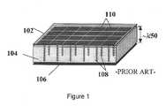
- FIG. 1An example of a known AMC is shown in FIG. 1 .
- the AMC 100 illustrated in FIG. 1is fabricated using conventional circuit technology and features an electrically-thin, planar, periodic structure, referred to as a frequency selective surface (FSS) 102 .
- the periodic structureincludes capacitive patches 110 that are connected to a conductive ground plane 106 by means of metal vias or posts 108 .
- the posts 108pass through a spacer layer 104 that consists of a dielectric material having a relatively low permeability.
- spacer layer 104is typically 10-40 times thicker than the FSS 102
- one advantage of AMCsis that the entire structure (FSS, spacer layer, and ground plane) has a much smaller thickness than the free space wavelengths of the frequencies over which the AMC operates, i.e. the wavelength at resonance.
- the periodicity of the periodic structureis much smaller than the free space wavelength, typically being ⁇ fraction (1/12) ⁇ to ⁇ fraction (1/40) ⁇ of the wavelength at resonance.
- the resonant frequency of an AMCis defined to be that frequency or frequencies at which the reflection phase angle for a plane wave at normal incidence is zero degrees.
- the effective sheet capacitance of the FSSis denoted as C, and is measured in Farads per unit square.
- the resonant frequency of an AMCmay be adjusted by varying either or both the inductance and the capacitance of the AMC.
- the AMCpermits wire antennas to be well matched, in terms of impedance, and radiate efficiently when the antennas are placed in close proximity to the FSS, usually less than ⁇ fraction (1/100) ⁇ of the wavelength from the surface.
- the physical structure of the AMCyields an equivalent transmission line model shown in FIG. 2 a and the equivalent lumped circuit model shown in FIG. 2 b .
- the capacitive FSSis modeled as a shunt capacitance, while the spacer layer is modeled as a transmission line or inductor.
- the AMC thicknessmust be relatively large.
- the AMC thicknessmust be at least 0.106 ⁇ o , corresponding to a physical thickness of 1.4 inches at a center frequency of 900 MHz. This thickness is too large for many practical applications.
- the resonant frequency, f oof the AMC is electronically adjusted or tuned by controlling the effective sheet capacitance C of its FSS layer.
- This type of reconfigurable AMCuses integration of varactor or PIN diodes into a single layer FSS where the bias voltage is applied using a resistive lattice which is coplanar with the diode array to adjust the capacitance.
- the inter-patch capacitance between the patchesis varied in this RAMC.
- Other RAMCsmay change the capacitance of the effective circuit by translating overlapping capacitive patches on different layers and altering the overlap between the two sets of patches.
- RAMCsWhile having a wide frequency coverage for a given AMC thickness, may have a problem with intermodulation distortion as power levels become significant. Intermodulation distortion is always present when the radio frequency (RF) electronic control devices are used to tune the capacitance in the communication systems.
- RFradio frequency
- the solid state approaches used aboveproduce intermodulation products in the radiated spectrum when antennas are integrated into RAMCs. It would thus be advantageous to provide an RAMC and that has a broad tuning bandwidth of at least an octave while simultaneously minimizing intermodulation distortion.
- the present RAMCAt least one of the inductance or capacitance is varied.
- the present RAMChas such a broad tuning bandwidth and minimization of intermodulation distortion.
- the use of RF electronicsis reduced, which permits the device to operate in the presence of high RF fields and currents.
- intermodulation products in the RAMCare expected to be very low due to the absence of nonlinear devices.
- the artificial magnetic conductorcomprises a ground plane and a frequency selective surface (FSS).
- the FSShas capacitive patches, at least some of which are electrically connected with the ground plane.
- the distance between the FSS and the ground planeis variable.
- the position of one or both of the FSS and ground planemay be adjustable.
- the distance between the FSS and ground planemay be limited to less than the maximum distance between the FSS and ground plane.
- the distance between the twomay be reversibly varied, varied once and only once, or varied in a single direction.
- the distancemay be varied in discrete amounts or continuously by a linear actuator such as a manually (i.e. by hand not via a motor) or with the aid of a motor.
- the AMCmay also include spring contact probes or spring tabs, which are used to connect the capacitive patches of the FSS with the ground plane.
- the spring tabsmay be thin, bent in one or more positions, freely or permanently contact the FSS. Threaded shafts may be used to engage with vias in either of the FSS and ground plane to vary the distance between the two.
- Any movable member(either or both of the FSS and ground plane) may be reinforced by a buttressing mechanism, such as a board stiffener.
- the board stiffenermay be non-metallic.
- the spacer layer between the FSS and ground planemay be filled substantially with air or a dielectric having a relatively low permittivity.
- the equivalent transmission line circuit of the AMChas an inductor of variable inductance in parallel with a capacitor.
- the conductormay have a constant capacitance.
- the inductancemay be defined by a permeability multiplied by a multiplier.
- the permeabilitymay be constant while the multiplier is variable.
- the resonant frequency of the AMCmay be adjustable over at least a 3:1 or about a 10-15% tuning ratio by varying the inductance.
- the inductancemay be either continuously variable or variable by discrete amounts. Further, the inductance may be either reversibly variable, variable once and only once, or variable only in a single direction, increasing or decreasing.
- the AMCcontains the ground plane and two FSS layers. At least one of these is movable and at least one has a constant position.
- the FSS layershave at least one set of capacitive patches associated with each layer. This is to say that one or more of the FSS layers may have multiple layers of capacitive patches disposed at different positions on that FSS (most frequently opposing surfaces).
- a method of effecting a broad tuning bandwidth of at least an octave while simultaneously minimizing intermodulation distortion in an AMCcomprises varying a distance between a ground plane and a FSS of the AMC.
- a method of effecting a broad tuning bandwidth of at least an octave while simultaneously minimizing intermodulation distortion in an AMC an equivalent transmission line circuitcomprises varying an inductance of the equivalent lumped circuit model of the AMC.
- AMCsmay use the AMCs described above, for example: an antenna, a telephone, a personal digital assistant, a portable wireless device, or a computer.
- FIG. 1is a cross-sectional view of a conventional AMC
- FIGS. 2 a and 2 billustrate an equivalent transmission line and circuit of the structure of FIG. 1;
- FIG. 3is a top view of the RAMC of the first embodiment
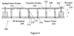
- FIG. 4is a cross-sectional view of the RAMC of the first embodiment
- FIG. 5illustrates an equivalent lumped circuit model of the RAMC of FIGS. 3 and 4;
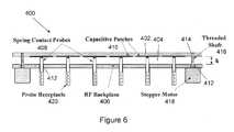
- FIG. 6is a cross-sectional view of the RAMC of the second embodiment
- FIG. 7is a partial view of the RAMC of the third embodiment.
- FIG. 8is a cross-sectional view of the RAMC of the third embodiment.
- FIG. 9is a cross-sectional view of the RAMC of a fourth embodiment.
- FIG. 10is a cross-sectional view of the RAMC of a fifth embodiment.
- RAMCreconfigurable artificial magnetic conductor
- AMCpassive artificial magnetic conductor
- Approaches for tuning the inductanceinclude moving either the ground plane or frequency selective surface (FSS) mechanically.
- a mechanically reconfigurable AMCis that it permits adjacent wire or strip antenna elements to radiate efficiently over a relatively broad tunable bandwidth, of at least approximately 3:1 in resonant frequency, when the elements are placed in close proximity to the RAMC surface (as little as ⁇ 0 /200 separation where ⁇ o is the AMC resonant wavelength).
- a linear actuatorprovides an additional advantage, varying the resonant frequency linearly with changes in the physical characteristics of the RAMC.
- the bandwidthcan be tuned by adjusting the position of one or more layers of the structure, thereby altering the distance between layers and consequently changing either or both the effective inductance and capacitance of the structure.
- FIGS. 4-8illustrate embodiments in which the effective inductance is changed
- FIGS. 9-10show embodiments in which the effective capacitance is altered.
- FIGS. 3 and 4show a top and cross-sectional view, respectively, of one embodiment of a RAMC 200 .
- FIG. 4is a cross sectional view of the RAMC 200 taken along line A-A′ in FIG. 3 .
- the RAMC 200has a FSS 202 with a periodic structure of capacitive patches (or conductive patches) 204 , which is usually a two dimensional array.
- the FSS 202may be fabricated from a circuit board and the capacitive patches 204 are formed of a conductive material, e.g. metal such as copper or metal alloys.
- the capacitance of the FSS 202may be constant.
- the term FSS as used hereinincludes the substrate on which the capacitive patches are disposed.
- This substrateis typically a printed circuit board substrate well known in the art. Although only a single layer of capacitive patches 204 are shown, multiple layers of capacitive patches may also be used to increase the capacitance, as shown in FIGS. 9 and 10 and described later (and also discussed in the application incorporated by reference).
- the FSS 202contains threaded vias. These vias may be threaded holes, PEM nuts, or other threaded inserts or fasteners, which are anchored to the printed circuit substrate.
- an FSS assemblymay include one or more layers of capacitive patches in addition to threaded vias that permit mechanical attachment and vertical movement of the FSS assembly.
- the terms FSS and FSS assemblyare used interchangeably herein.
- the RAMC 200also includes a spacer layer 206 , a ground plane (or RF backplane) 208 and conductive posts 210 .
- the spacer layer 206separates the FSS 202 and the ground plane 208 .
- the spacer layer 206may comprise a dielectric material having any suitable permittivity.
- the spacer layer 206is air filled, although a material such as foam may alternatively be used.
- a solid material filling the spacer layer 206may serve to increase stabilization of the overall RAMC structure against environmental factors such as vibration or temperature variation.
- a relatively low permittivity layeris preferred because, for a given physical thickness (i.e.
- the ground plane 208has at least one layer that is continuous and fabricated from a conductive material, e.g. an appropriate metal such as aluminum.
- the conductive posts 210are preferably formed from metal or a metal alloy and electrically connect the capacitive patches 204 with the ground plane 208 through an air-filled or other low permittivity dielectric-filled spacer layer 206 .
- the use of a metalpermits adequate electrical connection along with ease of temporary connection or permanent attachment.
- Each post 210is associated with a patch 204 of the FSS 202 and may be a spring contact probe, as shown, which is adjustable in height.
- the spring contact probes 210electrically connect the FSS 202 with the ground plane 208 .
- Each spring contact probe 210includes a probe tip 212 and a spring 214 housed in a probe receptacle 216 . While FIG.
- the probe receptacles 216are soldered or otherwise attached into through holes 224 in the ground plane 208 , they may also be installed upside down to this, i.e. such that the barrel or receptacle 216 is soldered to the FSS 202 .
- the probe tip 212may be either temporarily connected with the patch 204 through the force of the spring or may be permanently attached, such as by soldering. Soldering may be facilitated by a plated through hole (not shown) in the FSS.
- Typical spring contact probes 210 in the RAMC 200have a length between 0.5′′ and 1.5′′, which are appropriate for VHF and UHF frequency RAMCs, and may be supplied by Interconnect Devices, Inc. or Coda Systems, for example. Such probes have a collapsed length of about 70-80% of the extended length, thereby limiting the minimum distance between the FSS 202 and the ground plane 208 . Although a specific ratio of the collapsed/extended length of the probes is given, it is merely exemplary; the ratio may be any ratio dependent on the particular probe used.
- the RAMC 200has the equivalent transmission line circuit 300 shown in FIG. 5 .
- This circuit 300includes a capacitance 302 and an inductance 304 in parallel with the capacitance 302 .
- the circuit 300and thus RAMC 200 , has a resonant frequency defined by the parallel combination of the capacitance 302 and inductance 304 .
- the capacitance 302models effective sheet capacitance of the FSS 202 and the inductance 204 models the effective inductance of the spacer layer 204 containing the spring contact probes 210 .
- the inductance 304is defined by the permeability of the spacer layer 206 multiplied by the height of the spring contact probes 210 .
- the inductance 304is variable because the height of the spring contact probe 210 is variable, while the capacitance 302 is constant and, in this embodiment, the variation in the resonant frequency of the RAMC 200 is controlled substantially solely by the height of the spring contact probe 210 .
- the reduction in AMC resonant frequency for the compressed spring contact probes 210is about 10-15% of the maximum frequency when the spring contact probes 210 are extended.
- the dimensions of the RAMC 200 including those of the periodic structuremay be chosen such that the resonant frequency is in the VHF, UHF, L-band, or any other band as desired.
- a typical RAMC operating in the UHF bandmay have a nominal surface area of about 200-400 in. sq. and may have dozens, hundreds or more spring contact probes.
- threaded shafts 218are engaged with threaded holes 222 in the FSS 202 to adjust the distance (height) between the FSS 202 and the ground plane 208 .
- threaded insertscould be pressed into drilled holes in the FSS 202 rather than the threaded holes 222 in order to form the threaded vias that engage the threaded shafts 218 .
- the FSS 202is reversibly moved either toward or away from the ground plane 208 as desired.
- the threaded holes 222go all the way through the entire circuit board that comprises the FSS 202 such that the threaded shafts 218 may protrude from the threaded holes 222 , dependent on the distance h between the FSS 202 and the ground plane 208 .
- a miniature motor 220such as a stepping motor, is attached to the ground plane 208 and rotates the threaded shafts 218 .
- the motor 220is disposed between the FSS 202 and the ground plane 208 but is not taller than the probe receptacle 214 so that the spring contact probe 210 can be recessed by the maximum amount.
- the motor 220is controlled by external control elements (not shown).
- the RAMC 200may be integrated with a radio transceiver which controls tuning, reception and transmission of radio signals through an antenna (not shown) formed in part by the RAMC 200 .
- a control circuitapplies appropriate signals to control the inductance of the RAMC 200 , which in turn controls the resonant frequency of the RAMC 200 .
- a stepping motorhas been mentioned as an actuator, other linear actuators, such as a pancake motor, or may also be used.
- screws, scissor jacks, or other comparable mechanismsmay replace the threaded shafts 218 and the motor 220 eliminated.
- the threaded viasmay not be necessary, e.g. the top of the screw or scissor jack disposed on the bottom of the movable FSS, which would decrease assembly time and expense.
- the screwsfor example, are linear actuators that are manually operated by hand rather than motorized.
- the distance between the FSS 202 and the ground plane 208may not be reversible. This is to say that the distance between the two may be adjusted once and only once, a single permanent adjustment to set the resonant frequency of the RAMC 200 .
- the distancemay be adjusted in only one direction, increasing or decreasing, corresponding to the FSS 202 moving away from or towards the ground plane 208 .
- the FSS 202may be permanently deformed to set the frequency of the RAMC 200 .
- RAMCsin which the distance is varied in discrete amounts rather than being varied continuously. This may have advantages in speed and convenience in tuning from one frequency to another, for example from one frequency band to another. Numerous ways are known in the art to effect discrete limitations on the distance and will not be described here for brevity.
- the position of the FSS 202is adjusted while the ground plane 208 remains unmoved.
- the position of the ground planemay be varied while the position of the FSS remains constant or both may be varied.
- FIG. 6One example of an embodiment in which the position of the ground plane is varied is shown in FIG. 6 .
- the FSS 402has threaded holes 414 that engage with the threaded shafts 416 but may not pass all the way through the top of the FSS 402 .
- the spacer layer 404separates the FSS 402 from the ground plane 406 and the spring contact probes 408 electrically connect the capacitive patches 410 of the FSS 402 with the RF backplane 406 .
- the ground plane 406has unthreaded holes 412 through which the threaded shafts 416 pass and which are larger than the threaded shafts 416 .
- the miniature motor 418 to which the threaded shafts 416 are connectedis disposed below the ground plane 406 , i.e. on the opposite side of the ground plane 406 from the FSS 402 .
- the probe receptacles 420 of the spring contact probes 408are press fit into some of the holes 412 in the ground plane 406 .
- the probe receptacles 420may also be soldered, conductive glued, screwed, or bayonet mounted into the holes 412 , for example.
- the holes 412 in the ground plane 406may be fabricated similar to the holes 414 in the FSS 402 by drilling or any other conventional manner.
- the probe receptacles 420are fit into the holes 412 in the RF backplane 406 such that the apertures of the probe receptacles 420 are substantially flush with the upper surface of the ground plane 406 .
- the spacer layer 404decreases as the height decreases, as does the inductance of the effective circuit above. This, in turn, allows the distance between the FSS 402 and the ground plane 406 to be varied over at least a 10:1 ratio while maintaining the compactness of the RAMC 400 .
- the variation in distancecorresponds to at least a 3:1 tuning ratio of the RAMC resonant frequency.
- RAMC 400As compared with the RAMC of the first embodiment, however, is that the total thickness is larger than that of the RAMC 200 of the first embodiment due to the probe receptacles 420 protruding from the lower surface of the ground plane or RF backplane 406 .
- FIG. 8Another embodiment for a mechanically RAMC 600 is shown in FIG. 8 .
- a thin sheet 608 of spring metalsuch as Beryllium Copper
- spring tabs 610are flexible and form the electrical connections between the ground plane 612 and the capacitive patches 604 on the bottom of the FSS layer 602 .
- the thin sheet 608backed up by a mechanical supporting structure 606 , becomes the ground plane 612 (or RF backplane).
- the mechanical supporting structure 606 (or backplane support) that supports the thin sheet 608may be almost any rigid surface whose upper surface is conductive, such as an aluminum sheet.
- the rigid conducting surface 606may be substantially planar, but it is not necessary that this be the case.
- the spring tabs 610may have any number of shapes so long as they are in electrical contact with the patches 604 of the FSS layer 602 . Although four different shapes are depicted in FIG. 8, many others are possible.
- the spring tabs 610may be temporarily connected with or permanently attached to the capacitive patches 604 . This is to say that the electrical contact of the spring tabs 610 to the capacitive patches 604 may be established through spring contact (i.e. freely/removably) or may be permanently affixed, e.g. by solder. Permanent contact may be accomplished by a surface mounting operation or by inserting tabs into plated through holes.
- the spring tabs 610contact substantially the center of the capacitive patches 604 .
- the spring tabs 610are relatively narrow with respect to the length of the spring tabs 610 and contain at least one bend at a position intermediate between the ends of the spring tab such that the total height of the spring tabs is adjustable with minimal applied compressive force.
- a rigid conductive support structureis used to back the stamped metal and to allow transfer of compressive force to the spring tabs 610 .
- the distance between the FSS 602 and ground plane 612can be adjusted with a variety of mechanical approaches described above.
- the pattern of the patches in the previous embodimentsare arranged in a regular pattern and the patches themselves are substantially square in shape, as shown in FIG. 3, the pattern of the patches as well as the patch shape is not limited thereto.
- substantially circular, hexagonal, diamond, or triagonal patch shapesmay be used. Changing the size of patches and/or the periodicity, will change the TM mode cutoff frequency, resulting in a larger or smaller surface wave bandgaps.
- Particular geometrical configurationsmay be chosen to optimize performance factors such as resonance frequency or frequencies, size, weight, and so on.
- the FSS of the above embodimentmay be manufactured using a conventional printed circuit board process to print the patches on one or both surfaces of the FSS, other manufacturing technology may be substituted for this process.
- the above embodimentsdescribe embodiments in which the position of only one of the FSS and ground plane may be adjusted, other embodiments are possible in which the positions of both of the layers are varied.
- the present embodimentsdescribe RAMCs whose surface impedance is isotropic for both transverse polarizations of electric fields due to the symmetry of the patches. It is possible to spoil this symmetry (ignoring edge effects), for example by employing rectangular patches in place of square patches. Such asymmetry can cause the AMC resonance to be polarization specific, but the AMC will still exhibit properties of a high impedance surface, and it will still be tunable. However, the surface wave bandgap may be adversely affected, or even disappear.
- FIG. 7illustrates one solution to this problem: an RAMC 500 employing a board stiffener 502 to reduce the bending of the FSS 504 and ground plane 506 .
- the spring contact probes and other features of the RAMC 500have been omitted for clarity.
- the board stiffener 502may be soldered to the FSS 504 or ground plane 506 using mounting tabs (not shown) in the board stiffener 502 and matched through holes in the layer (not shown). Similarly the board stiffener 502 may be attached/mounted in any other similar fashion.
- a commercially available lightweight metal (e.g. aluminum) diaphragmmay be used as the board stiffener 502 if disposed below the RF backplane 506 .
- the board stiffener 502stiffens either the FSS 504 or stiffens the ground plane 506 and is disposed in the spacer layer 508 .
- non-metallic materialsmust be used for the board stiffener 502 to avoid perturbing the electromagnetic fields in the spacer layer 508 .
- the stiffenermay be fabricated from conventional PC board material in which the metal has been etched away. Note that although not shown, multiple stiffeners of different materials may be used to reinforce the different layers.
- the stiffenersmay be disposed within the spacer layer 508 (on the inner surfaces of the layers), thereby limiting the range of height variation but reducing the overall thickness of the structure, or may be disposed on the outer surfaces of the layers, thereby increasing the overall thickness of the structure but allowing a greater ratio of tuning since the height may be decreased to a smaller value.
- FIG. 9shows a cross-sectional view of a fourth embodiment of a RAMC 700 . While the materials that comprise the RAMC 700 remain essentially the same as those of the embodiments above, the structure is somewhat different.
- a first set of capacitive patches 710 ais disposed on the lower surface of a first FSS 702 a and a second set of capacitive patches 710 b is disposed on the lower surface of a second FSS 702 b .
- the first and second set of capacitive patches 710 a and 710 boverlap, thereby forming a capacitance between the two FSS layers that is in general substantially larger than the planar capacitance produced by the particular array of capacitive patches on either FSS layer alone.
- a first spacer layer 704 a of height h 1separates the upper and lower FSS 702 a and 702 b from each other while a second spacer layer 704 b of height h 2 separates the lower FSS 702 b from the ground plane 706 (or RF backplane).
- the first and second spacer layers 704 a and 704 bare formed from the same type of materials as the spacer layer in the previous embodiments.
- Fixed posts 714whose height is not adjustable, electrically connect the capacitive patches 710 b of the lower FSS 702 b with the RF backplane 706 .
- Spring contact probes 708electrically connect the capacitive patches 710 a of the upper FSS 702 a with the RF backplane 706 .
- the height of the spring contact probes 708is adjustable.
- only the position of the upper FSS 702 ais adjustable and thus the distance between the upper and lower FSS 710 a and 710 b (and capacitive patches disposed thereon) is adjustable.
- the lower FSS 704 bcontains via holes (not shown) that are larger than the tips 712 of the spring contact probes 708 and through which the tips 712 of the spring contact probes 708 pass.
- the spring contact probes 708are essentially the same as those of previous embodiments, e.g. having a probe receptacle 720 and a tip 712 that is temporarily connected with or permanently affixed to the first set of capacitive patches 710 a .
- the fixed posts 714are formed from the same types of material as the spring contact probes 708 , e.g. metal or a metallic alloy.
- the fixed posts 714contact the second set of capacitive patches 710 b substantially at the center of the second set of capacitive patches 710 b, similar to the spring contact probes 708 , which contact the first set of capacitive patches 710 a substantially at the center of the first set of capacitive patches 710 a.
- the ground plane 706 and lower FSS 702 bhave unthreaded holes (not shown) through which threaded shafts 716 pass and which are larger than the threaded shafts 716 .
- the upper FSS 702 ahas threaded holes (not shown) fitted to and in contact with the threaded shafts 716 and through which the threaded shafts 716 pass.
- a nut 718to which the threaded shaft 716 is connected, is disposed below the ground plane 706 , i.e. on the opposite side of the ground plane 706 from the FSS 702 a and 702 b .
- the nut 718is turned to adjust the position of the upper FSS 702 a .
- Another nut 722is used to limit the range of motion of the upper FSS 702 a , i.e. the FSS 702 a is limited to a distance of not larger than h 1 from the lower FSS 702 b.
- the threaded shafts 716may be formed from any suitable material, conductive (such as metal) or non-conductive (such as resin), as long as the motion of the shaft 716 adjusts the distance between the upper and lower FSS 702 a and 702 b .
- the threaded shafts 716 and nut 722do not contact the capacitive patches on either the upper or lower FSS 702 a or 702 b.
- the capacitive patchesare disposed on the lower surface of each FSS.
- placement of the capacitive patches on the lower surface of the FSSis not required; the capacitive patches may be disposed on the upper surface of either (or both) FSS.
- One benefit of an embodiment in which capacitive patches are disposed on the upper surface of the lower FSS and on the lower surface of the upper FSS as opposed to an embodiment in which capacitive patches are disposed on the same surface of both the lower and upper FSSis that the effective capacitance is increased for the same structure. This, in turn, decreases the resonant frequency of the overall RAMC or permits the size of the RAMC to be changed correspondingly to achieve the same frequency.
- each FSScontains capacitive patches
- capacitive patchesmay be present on both surfaces of either (or both) FSS or buried in the structure supporting the FSS (e.g. the printed circuit board).
- Multiple layers of capacitive patches that are disposed at different vertical positionshave the advantage of creating multiple resonant frequencies as described more fully in the application incorporated by reference.
- the lower FSSmay be connected with the RF backplane through adjustable spring contact probes while the upper FSS, rather than the lower FSS may be connected with the RF backplane through fixed posts.
- the number of fixed postsmay be reduced or the fixed posts may be eliminated altogether and a solid dielectric spacer layer used instead.
- the latter arrangementis also called a thinned-via array and may provide more mechanical stability than using fixed posts.
- FIG. 10Another RAMC 800 having multiple FSS layers is shown in FIG. 10 .
- This embodimentis a thinned-via RAMC that is similar to the previous RAMC 700 , with one important difference.
- the spring contact probesare replaced by spring mechanisms 808 that surround the threaded shafts 816 and are disposed between the upper and lower FSS 802 a and 802 b .
- the first set of capacitive patches 810 ais left floating (i.e. at a floating potential or non-grounded) while the second set of capacitive patches 810 b is connected to the RF backplane 806 through the fixed posts 814 .
- Advantages of such an arrangementinclude a decrease in material costs as a few simple spring mechanisms 808 are used replace a large number of spring contact probes as well as a decrease in fabrication costs as no soldering or permanent fixture is required, nor is attachment of the probe receptacle to the RF backplane 806 .
- the threaded shaftsmay be disposed at regular intervals throughout the RAMC to prevent significant flexure in the substrate containing the upper FSS.
- the nuts 818 used to adjust the heightmay be replaced by a motor such as a stepper motor.
- the present inventionprovides a reconfigurable artificial magnetic conductor (RAMC) that allows for wide frequency coverage, while the mechanical approach to tuning the RAMC permits linear response and the accommodation of high RF power levels without substantial intermodulation distortion.
- the inductance in the equivalent circuit of the RAMCis controlled, thus controlling its high impedance properties.
- the probe receptacles of the spring contact probesare disposed either within the spacer layer or below the RF backplane. In the former case, the overall thickness of the RAMC is decreased, while in the latter case the range of variation of the thickness is increased.
- the AMCmay be part of an antenna.
- Such an antennamay be used in a communication system in portable electronics, for example a telephone, personal digital assistant, portable wireless device or computer.
- a printed monopole antennamay be located on the upper surface of FSS layers 702 a or 802 a in FIG. 9 or 10 .
Landscapes
- Physics & Mathematics (AREA)
- Optics & Photonics (AREA)
- Control Of Motors That Do Not Use Commutators (AREA)
Abstract
Description

Claims (52)
Priority Applications (1)
| Application Number | Priority Date | Filing Date | Title |
|---|---|---|---|
| US10/246,035US6690327B2 (en) | 2001-09-19 | 2002-09-18 | Mechanically reconfigurable artificial magnetic conductor |
Applications Claiming Priority (2)
| Application Number | Priority Date | Filing Date | Title |
|---|---|---|---|
| US32340801P | 2001-09-19 | 2001-09-19 | |
| US10/246,035US6690327B2 (en) | 2001-09-19 | 2002-09-18 | Mechanically reconfigurable artificial magnetic conductor |
Publications (2)
| Publication Number | Publication Date |
|---|---|
| US20030052757A1 US20030052757A1 (en) | 2003-03-20 |
| US6690327B2true US6690327B2 (en) | 2004-02-10 |
Family
ID=26937660
Family Applications (1)
| Application Number | Title | Priority Date | Filing Date |
|---|---|---|---|
| US10/246,035Expired - Fee RelatedUS6690327B2 (en) | 2001-09-19 | 2002-09-18 | Mechanically reconfigurable artificial magnetic conductor |
Country Status (1)
| Country | Link |
|---|---|
| US (1) | US6690327B2 (en) |
Cited By (29)
| Publication number | Priority date | Publication date | Assignee | Title |
|---|---|---|---|---|
| US20040021607A1 (en)* | 2002-07-31 | 2004-02-05 | Alcatel | Multisource antenna, in particular for systems with a reflector |
| US20040027286A1 (en)* | 2001-06-26 | 2004-02-12 | Gregory Poilasne | Multi frequency magnetic dipole antenna structures and methods of reusing the volume of an antenna |
| US20040263420A1 (en)* | 2003-04-11 | 2004-12-30 | Werner Douglas H | Pixelized frequency selective surfaces for reconfigurable artificial magnetically conducting ground planes |
| US20050029632A1 (en)* | 2003-06-09 | 2005-02-10 | Mckinzie William E. | Circuit and method for suppression of electromagnetic coupling and switching noise in multilayer printed circuit boards |
| US20050104678A1 (en)* | 2003-09-11 | 2005-05-19 | Shahrooz Shahparnia | System and method for noise mitigation in high speed printed circuit boards using electromagnetic bandgap structures |
| US20050134521A1 (en)* | 2003-12-18 | 2005-06-23 | Waltho Alan E. | Frequency selective surface to suppress surface currents |
| US20050134522A1 (en)* | 2003-12-18 | 2005-06-23 | Waltho Alan E. | Frequency selective surface to suppress surface currents |
| US20050205292A1 (en)* | 2004-03-18 | 2005-09-22 | Etenna Corporation. | Circuit and method for broadband switching noise suppression in multilayer printed circuit boards using localized lattice structures |
| US20060038639A1 (en)* | 2004-03-08 | 2006-02-23 | Mckinzie William E Iii | Systems and methods for blocking microwave propagation in parallel plate structures utilizing cluster vias |
| US20060170595A1 (en)* | 2002-10-01 | 2006-08-03 | Trango Systems, Inc. | Wireless point multipoint system |
| US20060202784A1 (en)* | 2004-03-08 | 2006-09-14 | Wemtec, Inc. | Systems and methods for blocking microwave propagation in parallel plate structures |
| US20070159401A1 (en)* | 2004-02-26 | 2007-07-12 | Baliarda Carles P | Handset with electromagnetic bra |
| US20080238801A1 (en)* | 2007-03-29 | 2008-10-02 | Lawrence Ragan | Conductor Having Two Frequency-Selective Surfaces |
| US20080266179A1 (en)* | 2007-04-24 | 2008-10-30 | Sony Ericsson Mobile Communications Ab | Electrical connection elements provided in the amc structure of an antenna arrangement |
| US20090201220A1 (en)* | 2006-04-04 | 2009-08-13 | Dong-Ho Kim | High impedance surface structure using artificial magnetic conductor, and antenna and electromagnetic device using the same structure |
| US20100007562A1 (en)* | 2007-02-14 | 2010-01-14 | Airbus Operations | Tuneable antenna for electromagnetic compatibility tests |
| US20100224950A1 (en)* | 2009-03-05 | 2010-09-09 | Rostam Dinyari | Apparatus and method using patterned array with separated islands |
| US7830310B1 (en)* | 2005-07-01 | 2010-11-09 | Hrl Laboratories, Llc | Artificial impedance structure |
| US7911407B1 (en) | 2008-06-12 | 2011-03-22 | Hrl Laboratories, Llc | Method for designing artificial surface impedance structures characterized by an impedance tensor with complex components |
| US20110156492A1 (en)* | 2009-12-30 | 2011-06-30 | Young Ho Ryu | Wireless power transmission apparatus using near field focusing |
| US20110250838A1 (en)* | 2010-04-11 | 2011-10-13 | Broadcom Corporation | Rf and nfc pamm enhanced electromagnetic signaling |
| US8212739B2 (en) | 2007-05-15 | 2012-07-03 | Hrl Laboratories, Llc | Multiband tunable impedance surface |
| CN105703042A (en)* | 2016-04-14 | 2016-06-22 | 南京大学 | S type miniaturized frequency selective surface formed broadband wave-transmission structure |
| US9548451B1 (en)* | 2009-01-16 | 2017-01-17 | The Boeing Company | Method of making antireflective apparatus |
| CN106532271A (en)* | 2015-09-11 | 2017-03-22 | 克洛纳测量技术有限公司 | Antenna with lenses |
| CN109687163A (en)* | 2018-12-12 | 2019-04-26 | 南京邮电大学 | Restructural phase-modulation screen based on three frequency Artificial magnetic conductor structures |
| US10312596B2 (en) | 2013-01-17 | 2019-06-04 | Hrl Laboratories, Llc | Dual-polarization, circularly-polarized, surface-wave-waveguide, artificial-impedance-surface antenna |
| US10983194B1 (en) | 2014-06-12 | 2021-04-20 | Hrl Laboratories, Llc | Metasurfaces for improving co-site isolation for electronic warfare applications |
| US20220278450A1 (en)* | 2021-03-01 | 2022-09-01 | Kyocera International Inc. | Low-Profile Low-Cost Phased-Array Antenna-in-Package |
Families Citing this family (15)
| Publication number | Priority date | Publication date | Assignee | Title |
|---|---|---|---|---|
| US7683445B2 (en)* | 2005-02-24 | 2010-03-23 | Everspin Technologies, Inc. | Enhanced permeability device structures and method |
| US8354975B2 (en)* | 2007-12-26 | 2013-01-15 | Nec Corporation | Electromagnetic band gap element, and antenna and filter using the same |
| JP5380919B2 (en) | 2008-06-24 | 2014-01-08 | 日本電気株式会社 | Waveguide structure and printed wiring board |
| GB2467763B (en) | 2009-02-13 | 2013-02-20 | Univ Kent Canterbury | Tuneable surface |
| US9269999B2 (en) | 2009-04-30 | 2016-02-23 | Nec Corporation | Structural body, printed board, antenna, transmission line waveguide converter, array antenna, and electronic device |
| CN103346408A (en)* | 2013-06-17 | 2013-10-09 | 哈尔滨工业大学 | Artificial magnetic conductor floor |
| US10439292B2 (en)* | 2017-04-04 | 2019-10-08 | The Johns Hopkins University | Electromagnetic energy shielding systems, apparatuses, and methods |
| US10439291B2 (en)* | 2017-04-04 | 2019-10-08 | The Johns Hopkins University | Radio frequency surface wave attenuator structures and associated methods |
| US10903569B2 (en)* | 2018-06-15 | 2021-01-26 | Huawei Technologies Co., Ltd. | Reconfigurable radial waveguides with switchable artificial magnetic conductors |
| US11399427B2 (en)* | 2019-10-03 | 2022-07-26 | Lockheed Martin Corporation | HMN unit cell class |
| JP6926174B2 (en)* | 2019-11-26 | 2021-08-25 | 京セラ株式会社 | Antennas, wireless communication modules and wireless communication devices |
| EP4218092B1 (en)* | 2020-10-14 | 2024-07-10 | Viasat, Inc. | Antenna apparatus and deployment method employing collapsible memory metal |
| EP4218091B1 (en)* | 2020-10-14 | 2024-12-04 | Viasat, Inc. | Deployable antenna apparatus with inflate to latch mechanism |
| CN113597246A (en)* | 2021-07-28 | 2021-11-02 | 维沃移动通信有限公司 | Shield case and electronic device |
| CN113809556A (en)* | 2021-08-05 | 2021-12-17 | 华南理工大学 | Common aperture dual frequency dual polarization antenna array and communication equipment |
Citations (10)
| Publication number | Priority date | Publication date | Assignee | Title |
|---|---|---|---|---|
| US4821041A (en)* | 1986-12-22 | 1989-04-11 | U.S. Philips Corporation | Patch antenna |
| US6081235A (en)* | 1998-04-30 | 2000-06-27 | The United States Of America As Represented By The Administrator Of The National Aeronautics And Space Administration | High resolution scanning reflectarray antenna |
| US6195047B1 (en)* | 1998-10-28 | 2001-02-27 | Raytheon Company | Integrated microelectromechanical phase shifting reflect array antenna |
| US6351240B1 (en)* | 2000-02-25 | 2002-02-26 | Hughes Electronics Corporation | Circularly polarized reflect array using 2-bit phase shifter having initial phase perturbation |
| US6411261B1 (en)* | 2001-02-26 | 2002-06-25 | E-Tenna Corporation | Artificial magnetic conductor system and method for manufacturing |
| US6441787B1 (en)* | 1998-10-28 | 2002-08-27 | Raytheon Company | Microstrip phase shifting reflect array antenna |
| US6476771B1 (en)* | 2001-06-14 | 2002-11-05 | E-Tenna Corporation | Electrically thin multi-layer bandpass radome |
| US6483480B1 (en)* | 2000-03-29 | 2002-11-19 | Hrl Laboratories, Llc | Tunable impedance surface |
| US6512494B1 (en)* | 2000-10-04 | 2003-01-28 | E-Tenna Corporation | Multi-resonant, high-impedance electromagnetic surfaces |
| US6525695B2 (en)* | 2001-04-30 | 2003-02-25 | E-Tenna Corporation | Reconfigurable artificial magnetic conductor using voltage controlled capacitors with coplanar resistive biasing network |
- 2002
- 2002-09-18USUS10/246,035patent/US6690327B2/ennot_activeExpired - Fee Related
Patent Citations (10)
| Publication number | Priority date | Publication date | Assignee | Title |
|---|---|---|---|---|
| US4821041A (en)* | 1986-12-22 | 1989-04-11 | U.S. Philips Corporation | Patch antenna |
| US6081235A (en)* | 1998-04-30 | 2000-06-27 | The United States Of America As Represented By The Administrator Of The National Aeronautics And Space Administration | High resolution scanning reflectarray antenna |
| US6195047B1 (en)* | 1998-10-28 | 2001-02-27 | Raytheon Company | Integrated microelectromechanical phase shifting reflect array antenna |
| US6441787B1 (en)* | 1998-10-28 | 2002-08-27 | Raytheon Company | Microstrip phase shifting reflect array antenna |
| US6351240B1 (en)* | 2000-02-25 | 2002-02-26 | Hughes Electronics Corporation | Circularly polarized reflect array using 2-bit phase shifter having initial phase perturbation |
| US6483480B1 (en)* | 2000-03-29 | 2002-11-19 | Hrl Laboratories, Llc | Tunable impedance surface |
| US6512494B1 (en)* | 2000-10-04 | 2003-01-28 | E-Tenna Corporation | Multi-resonant, high-impedance electromagnetic surfaces |
| US6411261B1 (en)* | 2001-02-26 | 2002-06-25 | E-Tenna Corporation | Artificial magnetic conductor system and method for manufacturing |
| US6525695B2 (en)* | 2001-04-30 | 2003-02-25 | E-Tenna Corporation | Reconfigurable artificial magnetic conductor using voltage controlled capacitors with coplanar resistive biasing network |
| US6476771B1 (en)* | 2001-06-14 | 2002-11-05 | E-Tenna Corporation | Electrically thin multi-layer bandpass radome |
Cited By (60)
| Publication number | Priority date | Publication date | Assignee | Title |
|---|---|---|---|---|
| US7012568B2 (en)* | 2001-06-26 | 2006-03-14 | Ethertronics, Inc. | Multi frequency magnetic dipole antenna structures and methods of reusing the volume of an antenna |
| US20040027286A1 (en)* | 2001-06-26 | 2004-02-12 | Gregory Poilasne | Multi frequency magnetic dipole antenna structures and methods of reusing the volume of an antenna |
| US20040021607A1 (en)* | 2002-07-31 | 2004-02-05 | Alcatel | Multisource antenna, in particular for systems with a reflector |
| US6927729B2 (en)* | 2002-07-31 | 2005-08-09 | Alcatel | Multisource antenna, in particular for systems with a reflector |
| US20080191946A1 (en)* | 2002-10-01 | 2008-08-14 | Trango Systems, Inc. | Wireless Point to Multipoint System |
| US7363058B2 (en)* | 2002-10-01 | 2008-04-22 | Trango Systems, Inc. | Wireless point multipoint system |
| US7835769B2 (en) | 2002-10-01 | 2010-11-16 | Trango Systems, Inc. | Wireless point to multipoint system |
| US20060170595A1 (en)* | 2002-10-01 | 2006-08-03 | Trango Systems, Inc. | Wireless point multipoint system |
| US20110053648A1 (en)* | 2002-10-01 | 2011-03-03 | Trango Systems, Inc. | Wireless Point to Multipoint System |
| US7420524B2 (en) | 2003-04-11 | 2008-09-02 | The Penn State Research Foundation | Pixelized frequency selective surfaces for reconfigurable artificial magnetically conducting ground planes |
| US20040263420A1 (en)* | 2003-04-11 | 2004-12-30 | Werner Douglas H | Pixelized frequency selective surfaces for reconfigurable artificial magnetically conducting ground planes |
| US7889134B2 (en) | 2003-06-09 | 2011-02-15 | Wemtec, Inc. | Circuit and method for suppression of electromagnetic coupling and switching noise in multilayer printed circuit boards |
| US20050029632A1 (en)* | 2003-06-09 | 2005-02-10 | Mckinzie William E. | Circuit and method for suppression of electromagnetic coupling and switching noise in multilayer printed circuit boards |
| US7215007B2 (en) | 2003-06-09 | 2007-05-08 | Wemtec, Inc. | Circuit and method for suppression of electromagnetic coupling and switching noise in multilayer printed circuit boards |
| US20070120223A1 (en)* | 2003-06-09 | 2007-05-31 | Wemtec, Inc. | Circuit and method for suppression of electromagnetic coupling and switching noise in multilayer printed circuit boards |
| US20050104678A1 (en)* | 2003-09-11 | 2005-05-19 | Shahrooz Shahparnia | System and method for noise mitigation in high speed printed circuit boards using electromagnetic bandgap structures |
| US20050134522A1 (en)* | 2003-12-18 | 2005-06-23 | Waltho Alan E. | Frequency selective surface to suppress surface currents |
| US20050134521A1 (en)* | 2003-12-18 | 2005-06-23 | Waltho Alan E. | Frequency selective surface to suppress surface currents |
| US7190315B2 (en)* | 2003-12-18 | 2007-03-13 | Intel Corporation | Frequency selective surface to suppress surface currents |
| US7456792B2 (en) | 2004-02-26 | 2008-11-25 | Fractus, S.A. | Handset with electromagnetic bra |
| US20070159401A1 (en)* | 2004-02-26 | 2007-07-12 | Baliarda Carles P | Handset with electromagnetic bra |
| US7449982B2 (en) | 2004-03-08 | 2008-11-11 | Wemtec, Inc. | Systems and methods for blocking microwave propagation in parallel plate structures |
| US7495532B2 (en) | 2004-03-08 | 2009-02-24 | Wemtec, Inc. | Systems and methods for blocking microwave propagation in parallel plate structures |
| US20080186111A1 (en)* | 2004-03-08 | 2008-08-07 | Wemtec, Inc. | Systems and methods for blocking microwave propagation in parallel plate structures |
| US20070146102A1 (en)* | 2004-03-08 | 2007-06-28 | Wemtec, Inc. | Systems and methods for blocking microwave propagation in parallel plate structures |
| US20070018757A1 (en)* | 2004-03-08 | 2007-01-25 | Mckinzie William E Iii | Systems and methods for blocking microwave propagation in parallel plate structures utilizing cluster vias |
| US7342471B2 (en) | 2004-03-08 | 2008-03-11 | Wemtec, Inc. | Systems and methods for blocking microwave propagation in parallel plate structures |
| US20060038639A1 (en)* | 2004-03-08 | 2006-02-23 | Mckinzie William E Iii | Systems and methods for blocking microwave propagation in parallel plate structures utilizing cluster vias |
| US20060202784A1 (en)* | 2004-03-08 | 2006-09-14 | Wemtec, Inc. | Systems and methods for blocking microwave propagation in parallel plate structures |
| US7157992B2 (en) | 2004-03-08 | 2007-01-02 | Wemtec, Inc. | Systems and methods for blocking microwave propagation in parallel plate structures |
| US7123118B2 (en) | 2004-03-08 | 2006-10-17 | Wemtec, Inc. | Systems and methods for blocking microwave propagation in parallel plate structures utilizing cluster vias |
| US7479857B2 (en) | 2004-03-08 | 2009-01-20 | Wemtec, Inc. | Systems and methods for blocking microwave propagation in parallel plate structures utilizing cluster vias |
| US20050205292A1 (en)* | 2004-03-18 | 2005-09-22 | Etenna Corporation. | Circuit and method for broadband switching noise suppression in multilayer printed circuit boards using localized lattice structures |
| US7830310B1 (en)* | 2005-07-01 | 2010-11-09 | Hrl Laboratories, Llc | Artificial impedance structure |
| US20090201220A1 (en)* | 2006-04-04 | 2009-08-13 | Dong-Ho Kim | High impedance surface structure using artificial magnetic conductor, and antenna and electromagnetic device using the same structure |
| US8421677B2 (en)* | 2007-02-14 | 2013-04-16 | Airbus Operations Sas | Tuneable antenna for electromagnetic compatibility tests |
| US20100007562A1 (en)* | 2007-02-14 | 2010-01-14 | Airbus Operations | Tuneable antenna for electromagnetic compatibility tests |
| US7990328B2 (en) | 2007-03-29 | 2011-08-02 | The Board Of Regents, The University Of Texas System | Conductor having two frequency-selective surfaces |
| WO2008121789A1 (en)* | 2007-03-29 | 2008-10-09 | The Board Of Regents, The University Of Texas System | Conductor having two frequency-selective surfaces |
| US20080238801A1 (en)* | 2007-03-29 | 2008-10-02 | Lawrence Ragan | Conductor Having Two Frequency-Selective Surfaces |
| US7595757B2 (en)* | 2007-04-24 | 2009-09-29 | Sony Ericsson Mobile Communications Ab | Electrical connection elements provided in the AMC structure of an antenna arrangement |
| US20080266179A1 (en)* | 2007-04-24 | 2008-10-30 | Sony Ericsson Mobile Communications Ab | Electrical connection elements provided in the amc structure of an antenna arrangement |
| US8212739B2 (en) | 2007-05-15 | 2012-07-03 | Hrl Laboratories, Llc | Multiband tunable impedance surface |
| US7911407B1 (en) | 2008-06-12 | 2011-03-22 | Hrl Laboratories, Llc | Method for designing artificial surface impedance structures characterized by an impedance tensor with complex components |
| US9548451B1 (en)* | 2009-01-16 | 2017-01-17 | The Boeing Company | Method of making antireflective apparatus |
| US20100224950A1 (en)* | 2009-03-05 | 2010-09-09 | Rostam Dinyari | Apparatus and method using patterned array with separated islands |
| US8629353B2 (en)* | 2009-03-05 | 2014-01-14 | The Board Of Trustees Of The Leland Stanford Junior University | Apparatus and method using patterned array with separated islands |
| US20110156492A1 (en)* | 2009-12-30 | 2011-06-30 | Young Ho Ryu | Wireless power transmission apparatus using near field focusing |
| US9013068B2 (en)* | 2009-12-30 | 2015-04-21 | Samsung Electronics Co., Ltd. | Wireless power transmission apparatus using near field focusing |
| US20110248901A1 (en)* | 2010-04-11 | 2011-10-13 | Broadcom Corporation | Multiple frequency projected artificial magnetic mirror and antenna application thereof |
| US8780003B2 (en)* | 2010-04-11 | 2014-07-15 | Broadcom Corporation | Multiple frequency projected artificial magnetic mirror and antenna application thereof |
| US9270030B2 (en)* | 2010-04-11 | 2016-02-23 | Broadcom Corporation | RF and NFC PAMM enhanced electromagnetic signaling |
| US20110250838A1 (en)* | 2010-04-11 | 2011-10-13 | Broadcom Corporation | Rf and nfc pamm enhanced electromagnetic signaling |
| US10312596B2 (en) | 2013-01-17 | 2019-06-04 | Hrl Laboratories, Llc | Dual-polarization, circularly-polarized, surface-wave-waveguide, artificial-impedance-surface antenna |
| US10983194B1 (en) | 2014-06-12 | 2021-04-20 | Hrl Laboratories, Llc | Metasurfaces for improving co-site isolation for electronic warfare applications |
| CN106532271A (en)* | 2015-09-11 | 2017-03-22 | 克洛纳测量技术有限公司 | Antenna with lenses |
| CN105703042A (en)* | 2016-04-14 | 2016-06-22 | 南京大学 | S type miniaturized frequency selective surface formed broadband wave-transmission structure |
| CN105703042B (en)* | 2016-04-14 | 2019-06-14 | 南京大学 | Broadband wave-transmitting structure composed of S-shaped miniaturized frequency selective surface |
| CN109687163A (en)* | 2018-12-12 | 2019-04-26 | 南京邮电大学 | Restructural phase-modulation screen based on three frequency Artificial magnetic conductor structures |
| US20220278450A1 (en)* | 2021-03-01 | 2022-09-01 | Kyocera International Inc. | Low-Profile Low-Cost Phased-Array Antenna-in-Package |
Also Published As
| Publication number | Publication date |
|---|---|
| US20030052757A1 (en) | 2003-03-20 |
Similar Documents
| Publication | Publication Date | Title |
|---|---|---|
| US6690327B2 (en) | Mechanically reconfigurable artificial magnetic conductor | |
| US6509882B2 (en) | Low SAR broadband antenna assembly | |
| US7446712B2 (en) | Composite right/left-handed transmission line based compact resonant antenna for RF module integration | |
| US8547286B2 (en) | Metamaterial antennas for wideband operations | |
| US6411261B1 (en) | Artificial magnetic conductor system and method for manufacturing | |
| US6882316B2 (en) | DC inductive shorted patch antenna | |
| US7911386B1 (en) | Multi-band radiating elements with composite right/left-handed meta-material transmission line | |
| US8279121B2 (en) | Antenna device and wireless communication apparatus | |
| US6680712B2 (en) | Antenna having a conductive case with an opening | |
| US7230573B2 (en) | Dual-band antenna with an impedance transformer | |
| US20080062045A1 (en) | Communication device with a low profile antenna | |
| US6504508B2 (en) | Printed circuit variable impedance transmission line antenna | |
| US6509875B1 (en) | Electronically tuned active antenna apparatus | |
| US12034212B2 (en) | Dual-polarization antenna module and electronic device comprising said antenna module | |
| CN118281576B (en) | Super-surface array structure and signal relay reflection device | |
| CN116404430B (en) | Low-profile circularly polarized frequency reconfigurable antenna | |
| US7868844B2 (en) | Ultra-wide bandwidth antenna | |
| WO2002087012A1 (en) | Pifa antenna with higp structure | |
| Latif et al. | Frequency reconfigurable antennas | |
| JP2001077622A (en) | Broadband antenna | |
| US8610639B2 (en) | Surface-independent body mount conformal antenna | |
| CN119362030B (en) | Super-surface array structure | |
| JP5365334B2 (en) | Planar antenna, radio module, and radio system | |
| WO2014036302A1 (en) | Miniaturized antennas | |
| Raj et al. | Pin loaded microstrip antenna for 2.45 GHz |
Legal Events
| Date | Code | Title | Description |
|---|---|---|---|
| AS | Assignment | Owner name:E-TENNA CORPORATION, MARYLAND Free format text:ASSIGNMENT OF ASSIGNORS INTEREST;ASSIGNOR:MCKINZIE, WILLIAM E. III;REEL/FRAME:013303/0699 Effective date:20020816 Owner name:TITAN SYSTEMS CORPORATION/AEROSPACE ELECTRONICS DI Free format text:ASSIGNMENT OF ASSIGNORS INTEREST;ASSIGNOR:SANCHEZ, VICTOR;REEL/FRAME:013314/0504 Effective date:20020821 | |
| AS | Assignment | Owner name:ETENNA CORPORATION, MARYLAND Free format text:CHANGE OF NAME;ASSIGNOR:E-TENNA CORPORATION;REEL/FRAME:014734/0383 Effective date:20021119 | |
| AS | Assignment | Owner name:TITAN AEROSPACE ELECTRONICS DIVISION, MARYLAND Free format text:ASSIGNMENT OF ASSIGNORS INTEREST;ASSIGNOR:ETENNA CORPORATION;REEL/FRAME:015583/0330 Effective date:20040401 | |
| FEPP | Fee payment procedure | Free format text:PAT HOLDER NO LONGER CLAIMS SMALL ENTITY STATUS, ENTITY STATUS SET TO UNDISCOUNTED (ORIGINAL EVENT CODE: STOL); ENTITY STATUS OF PATENT OWNER: LARGE ENTITY | |
| FPAY | Fee payment | Year of fee payment:4 | |
| REMI | Maintenance fee reminder mailed | ||
| REMI | Maintenance fee reminder mailed | ||
| LAPS | Lapse for failure to pay maintenance fees | ||
| STCH | Information on status: patent discontinuation | Free format text:PATENT EXPIRED DUE TO NONPAYMENT OF MAINTENANCE FEES UNDER 37 CFR 1.362 | |
| FP | Lapsed due to failure to pay maintenance fee | Effective date:20120210 |