US6690082B2 - High dopant concentration diffused resistor and method of manufacture therefor - Google Patents
High dopant concentration diffused resistor and method of manufacture thereforDownload PDFInfo
- Publication number
- US6690082B2 US6690082B2US10/256,466US25646602AUS6690082B2US 6690082 B2US6690082 B2US 6690082B2US 25646602 AUS25646602 AUS 25646602AUS 6690082 B2US6690082 B2US 6690082B2
- Authority
- US
- United States
- Prior art keywords
- doped
- resistor
- tub
- recited
- resistor region
- Prior art date
- Legal status (The legal status is an assumption and is not a legal conclusion. Google has not performed a legal analysis and makes no representation as to the accuracy of the status listed.)
- Expired - Lifetime
Links
Images


Classifications
- H—ELECTRICITY
- H10—SEMICONDUCTOR DEVICES; ELECTRIC SOLID-STATE DEVICES NOT OTHERWISE PROVIDED FOR
- H10D—INORGANIC ELECTRIC SEMICONDUCTOR DEVICES
- H10D84/00—Integrated devices formed in or on semiconductor substrates that comprise only semiconducting layers, e.g. on Si wafers or on GaAs-on-Si wafers
- H10D84/80—Integrated devices formed in or on semiconductor substrates that comprise only semiconducting layers, e.g. on Si wafers or on GaAs-on-Si wafers characterised by the integration of at least one component covered by groups H10D12/00 or H10D30/00, e.g. integration of IGFETs
- H10D84/811—Combinations of field-effect devices and one or more diodes, capacitors or resistors
- H—ELECTRICITY
- H10—SEMICONDUCTOR DEVICES; ELECTRIC SOLID-STATE DEVICES NOT OTHERWISE PROVIDED FOR
- H10D—INORGANIC ELECTRIC SEMICONDUCTOR DEVICES
- H10D1/00—Resistors, capacitors or inductors
- H10D1/40—Resistors
- H10D1/43—Resistors having PN junctions
- H—ELECTRICITY
- H10—SEMICONDUCTOR DEVICES; ELECTRIC SOLID-STATE DEVICES NOT OTHERWISE PROVIDED FOR
- H10D—INORGANIC ELECTRIC SEMICONDUCTOR DEVICES
- H10D84/00—Integrated devices formed in or on semiconductor substrates that comprise only semiconducting layers, e.g. on Si wafers or on GaAs-on-Si wafers
- H10D84/80—Integrated devices formed in or on semiconductor substrates that comprise only semiconducting layers, e.g. on Si wafers or on GaAs-on-Si wafers characterised by the integration of at least one component covered by groups H10D12/00 or H10D30/00, e.g. integration of IGFETs
- H10D84/811—Combinations of field-effect devices and one or more diodes, capacitors or resistors
- H10D84/817—Combinations of field-effect devices and resistors only
Definitions
- the present inventionis directed, in general, to integrated circuits and, more specifically, to a high dopant concentration diffused resistor, a method of manufacture therefor, and an integrated circuit including the same.
- CMOScomplementary metal oxide semiconductor
- CMOS devicesare complemented by other devices, such as resistors.
- resistorsare regularly required in analog CMOS and bipolar CMOS (BiCMOS) semiconductor devices to reduce current spikes associated with such devices.
- BiCMOSbipolar CMOS
- three broad categories of resistorsexist: interconnect resistors, polysilicon resistors, and diffused resistors.
- interconnect resistors and polysilicon resistorsare sparingly used.
- Diffused resistorsare also commonly broken into three categories: n-well diffused resistors, n+ diffused resistors and p+ diffused resistors, wherein the n+ diffused resistors and p+ diffused resistors are often collectively called high dopant concentration diffused resistors.
- the n-well diffused resistoris the most problematic. Many of the problems associated with the n-well diffused resistors may be ascribed to these resistors being highly voltage dependent. For this reason, n-well diffused resistors are the least desirable of the diffused resistors.
- the conventional p+ diffused resistor 100includes a conventional n-well 120 formed within a semiconductor substrate 110 .
- a p+ resistor region 130is formed within the n-well 120 , wherein the p+ resistor region 130 has contacts 140 contacting either side thereof.
- n+ diffused resistor 200in comparison to the p+ diffused resistor 100 , does not include the n-well 120 (FIG. 1 ), but its n+ resistor region 220 is formed directly in its semiconductor substrate 210 . Because the semiconductor substrate 210 is p-type doped, the n+ resistor region 220 is sufficiently isolated without using the n-well 120 (FIG. 1 ).
- the p+ and n+ diffused resistors 100 , 200are much more desirable than the standard n-well diffused resistor (and especially the interconnect resistors and polysilicon resistors), they do have certain drawbacks. For example, it has been observed that the p+ and n+ diffused resistors 100 , 200 , do not function as accurately and precisely as required for many of the high frequency devices being manufactured today.
- the bandwidth of the high frequency devicesis limited by certain features of the diffused resistors, mainly capacitances that form at the junction between the n-well 120 and the p+ resistor region 130 , and the semiconductor substrate 210 and n+ resistor region 220 , for the p+ diffused resistor 100 and n+ diffused resistor 200 , respectively.
- the present inventionprovides a high dopant concentration diffused resistor, a method of manufacture therefor, and an integrated circuit including the same.
- the high dopant concentration diffused resistorincludes a doped tub located over a semiconductor substrate and a doped resistor region located in the doped tub, the doped resistor region forming a junction within the doped tub.
- the high dopant concentration diffused resistorfurther includes first and second terminals each contacting the doped tub and the doped resistor region, wherein the first and second terminals cause the doped tub and doped resistor region to have a zero potential difference at any point across the junction when a voltage is applied to the first and second terminals. Often, this may be accomplished without adding additional processing steps.
- the high dopant concentration diffused resistorincludes a doped tub located over a semiconductor substrate and having a concentration of a first dopant, and a doped resistor region located in the doped tub and having a higher concentration of the first dopant.
- the resistorfurther includes a first terminal contacting the doped resistor region at a first location and an opposing second terminal contacting the doped resistor region at a second location, wherein the similar dopant between the doped tub and doped resistor region cause them to have a zero potential difference at any point across a junction therebetween when a voltage is applied to the first and second terminals.
- FIG. 1illustrates a Prior Art p+ diffused resistor
- FIG. 2illustrates a Prior Art n+ diffused resistor
- FIG. 3illustrates a partially completed integrated circuit constructed in accordance with the principles of the present invention, including a high dopant concentration diffused resistor located on a semiconductor substrate;
- FIG. 4illustrates a partially completed high dopant concentration diffused resistor constructed in accordance with the principles of the present invention, and more specifically, the formation of a doped resistor region;
- FIG. 5illustrates the partially completed high dopant concentration diffused resistor illustrated in FIG. 4, after formation of a first terminal and a second terminal, each contacting both the doped resistor region and a doped tub;
- FIG. 6illustrates a diagram showing the parallel resistors formed as a result of the first and second terminal formation of FIG. 5;
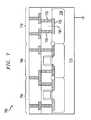
- FIG. 7illustrates a partially completed n+ diffused resistor in accordance with the principles of the present invention
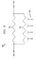
- FIG. 8illustrates a diagram showing the parallel resistors formed as a result of the similar dopant type used for the doped tub and the doped resistor region;
- FIG. 9illustrates an embodiment of the advantages realized by the p+ or n+ diffused resistors of FIGS. 3 and 7;
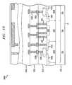
- FIG. 10illustrates a completed integrated circuit, which provides one environment where the resistor may be included.
- FIG. 3illustrated is a cross-sectional view of a partially completed integrated circuit 300 constructed in accordance with the principles of the present invention.
- the partially completed integrated circuit 300 in the embodiment illustrated in FIG. 3includes a completed high dopant concentration diffused resistor located over a semiconductor substrate 315 , wherein the high dopant concentration diffused resistor in this embodiment happens to be a p+ diffused resistor 310 . While the present embodiment focuses on the p+ diffused resistor 310 , those skilled in the art understand that any known or hereafter discovered high dopant concentration diffused resistor could be used.
- the completed p+ diffused resistor 310includes a doped tub 320 located over the semiconductor substrate 315 , and a doped resistor region 325 located within the doped tub 320 .
- the completed p+ diffused resistor 310as illustrated, further includes a first terminal 330 that contacts the doped tub 320 and the doped resistor region 325 , and an opposing second terminal 335 that contacts the doped tub 320 and the doped resistor region 325 .
- the doped tub 320 and the doped resistor region 325are a first dopant, and a second dopant opposite to the first dopant, respectively.
- the first dopantcomprises an n-type dopant and the second dopant comprises a p-type dopant.
- the semiconductor substrate 315may comprise the p-type dopant.
- ohmic contacts 332 , 337are located at points where the first and second terminals 330 , 335 , contact the doped tub 320 .
- the ohmic contacts 332 , 337may be island regions having a higher dopant concentration of the first dopant than the doped tub 320 .
- Other ohmic contacts 332 , 327are, however, within the scope of the present invention.
- Also included within the partially completed integrated circuit 300 illustrated in FIG. 3are conventionally formed transistor regions 350 , 360 .
- the conventional p+ and n+ diffused resistors 100 , 200illustrated in FIGS. 1 and 2 have parasitic capacitances associated therewith. It is believed that the parasitic capacitance arises because of a depletion region that forms at a p-n junction of each. The depletion region, in such an instance, tends to behave like an insulator located between two conductors, wherein the doped resistor region and the tub region behave like the two conductors. It is thought that a voltage differential across the p-n junction associated with diffused resistor tends to cause undesirable current leakage and power dissipation in high frequency semiconductor devices.
- the parasitic capacitanceis substantially reduced.
- the exemplary resistor of FIG. 3which is within the scope of the present invention, substantially diminishes the voltage differential across the doped tub 320 and doped resistor region 325 , by using the first terminal 330 that contacts the doped tub 320 and the doped resistor region 325 , and the opposing second terminal 335 that contacts the doped tub 320 and the doped resistor region 325 .
- This unique configurationsubstantially negates or counterbalances the effective parasitic capacitance.
- the first and second terminals 330 , 335cause the doped tub 320 and doped resistor region 325 to have a zero potential difference at any point across a junction therebetween, when a voltage is applied to the first and second terminals 330 , 335 .
- FIGS. 4 and 5illustrated are detailed manufacturing steps illustrating how one skilled in the art might manufacture a device similar to the partially completed integrated circuit illustrated in FIG. 3 .
- FIG. 4illustrates a cross-sectional view of a partially completed integrated circuit 400 at an intermediate manufacturing step.
- the partially completed integrated circuit 400includes a partially completed p+ diffused resistor region 410 , and conventional transistor regions 450 , 480 , all of which are located over a semiconductor substrate 415 .
- the transistor regions 450 , 480may be located adjacent the partially completed p+ diffused resistor region 410 .
- other design layoutsare also within the scope of the present invention.
- the semiconductor substrate 415may, in an exemplary embodiment, be any layer located in the integrated circuit 400 , including a wafer itself or a layer located above the wafer.
- the semiconductor substrate 415is a p-type substrate; however, one skilled in the art understands that the semiconductor substrate 415 could be an n-type substrate, without departing from the scope of the present invention. It should also be noted that in an exemplary embodiment the semiconductor substrate 415 may be grounded.
- the transistor regions 450 , 480include an n-type transistor tub 455 and a p-type transistor tub 485 , respectively.
- the type of dopant used to form the transistor tubsmay, however, be reversed without departing from the scope of the present invention.
- One having skill in the artunderstands how to form the n-type transistor tub 455 and the p-type transistor tub 485 , including protecting a region with a photoresist mask and subjecting an unprotected region to a desired dopant.
- the transistor regions 450 , 480further include conventionally formed source and drain regions 460 , 490 , respectively.
- the source and drain regions 460 , 490would be p-type doped and n-type doped, respectively. It should be well understood, however, in the case where the dopant included within the transistor tubs is reversed, the dopant included within the source and drain regions 460 , 490 , would also be reversed.
- the transistor regions 450 , 480may further include conventional transistors 495 , including gate oxides, polysilicon gates and oxide spacers.
- the partially completed integrated circuit 400includes the partially completed p+ diffused resistor region 410 .
- the partially completed p+ diffused resistor region 410includes a doped tub 420 .
- the doped tub 420in a previous step not shown, was doped with a first dopant.
- the first dopantis an n-type dopant, for example phosphorous or arsenic, and is doped to a concentration of about 1E16 atoms/cm 3 to about 1E17 atoms/cm 3 .
- the first dopantwould comprise a p-type dopant having a concentration of about 1E16 atoms/cm 3 to about 1E17 atoms/cm 3 .
- the doped tub 420may be formed concurrently with the similarly doped n-type transistor tub region 455 .
- This aspect of the present inventionis, of course, desirable because the concurrent formation of the doped tub 420 and the similarly doped n-type transistor tub region 455 saves valuable time and money.
- a doped resistor region 425located within the doped tub 420 .
- the doped resistor region 425includes a second dopant, opposite to that of the first dopant included within the doped tub 420 .
- the doped resistor region 425would include a p-type dopant, such as boron. The inverse would, again, also hold true where the doped tub 420 includes the p-type dopant and the semiconductor substrate 415 is an n-type substrate.
- the second dopantmay have a concentration ranging from about 1E18 atoms/cm 3 to about 1E19 atoms/cm 3 , which is similar to the dopant concentration included within the source and drain regions 460 , 490 .
- the doped resistor region 425may be formed concurrently with the similarly doped source and drain regions 460 . While it is desirable that the doped resistor region 425 and the similarly doped source and drain regions 460 be concurrently formed, it should be noted that the doped resistor region 425 may nonetheless be formed in an independent manufacturing step.
- FIG. 5illustrated is a cross-sectional view of the partially completed integrated circuit 400 illustrated in FIG. 4, after formation of a first terminal 510 and an opposing second terminal 520 .
- the first terminal 510 and the opposing second terminal 520are formed in a conventionally deposited interlevel dielectric layer 530 that overlays both the conventional transistors 495 and the partially completed p+ diffused resistor region 410 .
- the first terminal 510 and the opposing second terminal 520may be formed using conventional photolithographic processes to develop vias in the interlevel dielectric. Once the vias are formed, they are then filled with a conductive material, such as metal, and patterned with conventional processes to complete the terminals 510 and 520 .
- the layer of interconnect materialmay be formed, including conventional chemical vapor deposition (CVD), physical vapor deposition (PVD), or other similar known processes.
- the layer of interconnect materialmay comprise any known or hereinafter discovered conductive material generally used in the manufacture of semiconductor devices.
- the first terminal 510contacts the doped tub 420 and the doped resistor region 425
- the opposing second terminal 520also contacts the doped tub 420 and the doped resistor region 425
- FIG. 6illustrated is a circuit diagram 600 representing the p+ resistor region 410 illustrated in FIG. 5 .
- the doped tub 420behaves like a tub resistor 610 , wired in parallel with the doped resistor region 425 .
- thissubstantially reduces the parasitic capacitance, and therefore, substantially reduces the current leakage and power dissipation associated with the p+ resistor region 410 . Even though it is shown that there is a distributed capacitance 620 between the doped tub 420 (e.g., the tub resistor 610 ) and the semiconductor substrate 415 , the capacitance is relatively small because of the reduced dopant concentrations of the two layers.
- FIG. 7illustrated is a cross-sectional view of an alternative embodiment of a partially completed integrated circuit 700 constructed in accordance with the principles of the present invention.
- the partially completed integrated circuit 700 in the embodiment illustrated in FIG. 7includes an alternative embodiment of the completed high dopant concentration diffused resistor illustrated in FIG. 3 .
- the partially completed integrated circuit 700 in the embodiment illustrated in FIG. 7includes a completed n+ diffused resistor region 710 located over a semiconductor substrate 715 .
- the completed n+ diffused resistor region 710includes a doped tub 720 located over the semiconductor substrate 715 , and a doped resistor region 725 located within the doped tub 720 .
- the doped tub 720 and the doped resistor region 725both include the same type of dopant, however, the doped resistor region 725 includes a higher concentration of the dopant than the doped tub 720 .
- the doped tub 720includes an n-type dopant having a concentration of about 1E16 atoms/cm 3 to about 1E17 atoms/cm 3
- the doped resistor region 725includes the n-type dopant to a concentration ranging from about 1E18 atoms/cm 3 to about 1E19 atoms/cm 3 .
- the completed n+ diffused resistor region 710further includes a first terminal 730 that contacts the doped resistor region 725 , and an opposing second terminal 735 that also contacts the doped resistor region 725 .
- the first and second terminals 730 , 735do not also actually physically contact the doped tub 720 . Nonetheless, the similar dopant between the doped tub 720 and the doped resistor region 725 causes them to have a substantially equal potential value at any two adjacent points on either side of the doped tub 720 /doped resistor region 725 junction.
- the similar dopant between the doped tub 720 and doped resistor region 725causes them to have a zero potential difference at any point across a junction therebetween, when a voltage is applied to the first and second terminals 730 , 735 . Accordingly, the parasitic capacitance of the n+ diffused resistor region 710 is substantially reduced, similar to the p+ diffused resistor 310 of FIG. 3 .
- FIG. 8illustrated is a circuit diagram 800 representing the n+ diffused resistor region 710 illustrated in FIG. 7 .
- the doped tub 720behaves like a tub resistor 810 , wired in parallel with the doped resistor region 725 .
- there is no voltage differential across the doped tub 720 and the doped resistor region 725which substantially reduces the parasitic capacitance, and therefore, substantially reduces the current leakage and power dissipation associated with the n+ diffused resistor region 710 .
- the capacitance 820is relatively small because of the reduced dopant concentrations of the two layers. Further, current flowing through the doped tub 720 is also small because of its higher resistance. Accordingly, the net effect is quite beneficial.
- FIG. 9illustrated is a graph 900 illustrating one example of the benefits that may be realized using various aspects of the present invention.
- Graph 900compares the frequency response of a novel n+ diffused resistor similar to that of FIG. 7 (e.g., with a doped tub underneath), to that of a conventional n+ diffused resistor (e.g., without a doped tub underneath).
- line 910represents the novel device
- line 920represents the conventional device.
- Graph 900clearly shows that the bandwidth attainable at ⁇ 3 dB for the conventional device is half of what is attainable for the novel device. As is noticed, similar benefits may be achieved at other voltages.
- FIG. 10there is illustrated a cross-sectional view of a conventional integrated circuit 1000 that might include a completed resistor, similar to the above described completed resistor 310 .
- the integrated circuit 1000may include a CMOS device, a BiCMOS device, or other type of integrated circuit device.
- Shown in FIG. 10are components of the conventional integrated circuit 1000 , including: the transistor regions 350 , 360 , and dielectric layers 1010 , in which interconnect structures 1020 are formed (together forming interconnect layers).
- the interconnect structures 1020connect the transistor regions 350 , 360 , to other areas of the integrated circuit 1000 .
- Also shown in the integrated circuit 1000 illustrated in FIG. 10,are conventionally formed transistor tubs 1030 , 1040 , and source/drain regions 1050 , 1060 , respectively.
Landscapes
- Semiconductor Integrated Circuits (AREA)
- Metal-Oxide And Bipolar Metal-Oxide Semiconductor Integrated Circuits (AREA)
Abstract
Description
Claims (15)
Priority Applications (2)
| Application Number | Priority Date | Filing Date | Title |
|---|---|---|---|
| US10/256,466US6690082B2 (en) | 2001-09-28 | 2002-09-27 | High dopant concentration diffused resistor and method of manufacture therefor |
| US10/669,398US6784044B2 (en) | 2001-09-28 | 2003-09-24 | High dopant concentration diffused resistor and method of manufacture therefor |
Applications Claiming Priority (2)
| Application Number | Priority Date | Filing Date | Title |
|---|---|---|---|
| US32605001P | 2001-09-28 | 2001-09-28 | |
| US10/256,466US6690082B2 (en) | 2001-09-28 | 2002-09-27 | High dopant concentration diffused resistor and method of manufacture therefor |
Related Child Applications (1)
| Application Number | Title | Priority Date | Filing Date |
|---|---|---|---|
| US10/669,398DivisionUS6784044B2 (en) | 2001-09-28 | 2003-09-24 | High dopant concentration diffused resistor and method of manufacture therefor |
Publications (2)
| Publication Number | Publication Date |
|---|---|
| US20030062593A1 US20030062593A1 (en) | 2003-04-03 |
| US6690082B2true US6690082B2 (en) | 2004-02-10 |
Family
ID=26945389
Family Applications (2)
| Application Number | Title | Priority Date | Filing Date |
|---|---|---|---|
| US10/256,466Expired - LifetimeUS6690082B2 (en) | 2001-09-28 | 2002-09-27 | High dopant concentration diffused resistor and method of manufacture therefor |
| US10/669,398Expired - LifetimeUS6784044B2 (en) | 2001-09-28 | 2003-09-24 | High dopant concentration diffused resistor and method of manufacture therefor |
Family Applications After (1)
| Application Number | Title | Priority Date | Filing Date |
|---|---|---|---|
| US10/669,398Expired - LifetimeUS6784044B2 (en) | 2001-09-28 | 2003-09-24 | High dopant concentration diffused resistor and method of manufacture therefor |
Country Status (1)
| Country | Link |
|---|---|
| US (2) | US6690082B2 (en) |
Cited By (11)
| Publication number | Priority date | Publication date | Assignee | Title |
|---|---|---|---|---|
| US20040219744A1 (en)* | 2003-04-30 | 2004-11-04 | Oh Se-Hoon | Integrated circuit devices having pad contact plugs in the cell array and peripheral circuit regions of the integrated circuit substrate and methods of forming the same |
| US20050082522A1 (en)* | 2003-07-25 | 2005-04-21 | Yi-Chun Huang | Strained channel transistor formation |
| US20060124965A1 (en)* | 2003-07-25 | 2006-06-15 | Yee-Chia Yeo | Capacitor that includes high permittivity capacitor dielectric |
| US20060226512A1 (en)* | 2005-04-01 | 2006-10-12 | Stmicroelectronics S.A. | Integrated circuit comprising a substrate and a resistor |
| US20060226487A1 (en)* | 2003-08-18 | 2006-10-12 | Yee-Chia Yeo | Resistor with reduced leakage |
| US20060255365A1 (en)* | 2003-08-15 | 2006-11-16 | Chih-Hsin Ko | Structure and method of a strained channel transistor and a second semiconductor component in an integrated circuit |
| US20070194390A1 (en)* | 2006-02-22 | 2007-08-23 | Chinthakindi Anil K | Method of fabricating a precision buried resistor |
| US20080169484A1 (en)* | 2007-01-16 | 2008-07-17 | Harry Chuang | Strained Transistor with Optimized Drive Current and Method of Forming |
| US20090230439A1 (en)* | 2008-03-13 | 2009-09-17 | Yen-Sen Wang | Strain Bars in Stressed Layers of MOS Devices |
| US20100078725A1 (en)* | 2008-09-29 | 2010-04-01 | Yung-Chin Hou | Standard Cell without OD Space Effect in Y-Direction |
| US7888201B2 (en) | 2003-11-04 | 2011-02-15 | Taiwan Semiconductor Manufacturing Company, Ltd. | Semiconductor-on-insulator SRAM configured using partially-depleted and fully-depleted transistors |
Families Citing this family (7)
| Publication number | Priority date | Publication date | Assignee | Title |
|---|---|---|---|---|
| JP2006284979A (en)* | 2005-04-01 | 2006-10-19 | Hitachi Displays Ltd | Display device |
| US8384157B2 (en)* | 2006-05-10 | 2013-02-26 | International Rectifier Corporation | High ohmic integrated resistor with improved linearity |
| JP5371274B2 (en)* | 2008-03-27 | 2013-12-18 | ルネサスエレクトロニクス株式会社 | Semiconductor device |
| US7939894B2 (en)* | 2008-08-04 | 2011-05-10 | International Business Machines Corporation | Isolated high performance FET with a controllable body resistance |
| US8207580B2 (en)* | 2009-05-29 | 2012-06-26 | Power Integrations, Inc. | Power integrated circuit device with incorporated sense FET |
| EP3174096A1 (en)* | 2015-11-27 | 2017-05-31 | Nxp B.V. | Diffused resistor |
| CN113391667A (en) | 2020-03-12 | 2021-09-14 | 恩智浦美国有限公司 | Bias current generating circuit |
Citations (4)
| Publication number | Priority date | Publication date | Assignee | Title |
|---|---|---|---|---|
| JPH04163960A (en)* | 1990-10-26 | 1992-06-09 | Seiko Epson Corp | semiconductor integrated device |
| US5661332A (en)* | 1994-01-27 | 1997-08-26 | Nippondenso Co., Ltd. | Semiconductor diffused resistor |
| US6057204A (en)* | 1997-02-24 | 2000-05-02 | International Business Machines Corporation | Method of making a noise-isolated buried resistor by implanting a first well with a mask and then implanting an opposite conductivity well with a larger opening in the mask |
| US6376881B1 (en)* | 1999-11-18 | 2002-04-23 | Oki Electric Industry Co., Ltd. | Protective element formed in an SOI substrate for preventing a breakdown in an oxide film located below a diffused resistor |
Family Cites Families (5)
| Publication number | Priority date | Publication date | Assignee | Title |
|---|---|---|---|---|
| US5210438A (en)* | 1989-05-18 | 1993-05-11 | Fujitsu Limited | Semiconductor resistance element and process for fabricating same |
| JPH04373161A (en)* | 1991-06-22 | 1992-12-25 | Nec Corp | Semiconductor device |
| JPH0575026A (en)* | 1991-09-12 | 1993-03-26 | Matsushita Electron Corp | Manufacture of resistor element |
| DE69232257T2 (en)* | 1991-09-30 | 2002-08-08 | Texas Industries, Inc. | Insulation level controlled by depletion |
| CA2179246C (en)* | 1995-09-20 | 2000-10-24 | Kris Iniewski | Polysilicon defined diffused resistor |
- 2002
- 2002-09-27USUS10/256,466patent/US6690082B2/ennot_activeExpired - Lifetime
- 2003
- 2003-09-24USUS10/669,398patent/US6784044B2/ennot_activeExpired - Lifetime
Patent Citations (4)
| Publication number | Priority date | Publication date | Assignee | Title |
|---|---|---|---|---|
| JPH04163960A (en)* | 1990-10-26 | 1992-06-09 | Seiko Epson Corp | semiconductor integrated device |
| US5661332A (en)* | 1994-01-27 | 1997-08-26 | Nippondenso Co., Ltd. | Semiconductor diffused resistor |
| US6057204A (en)* | 1997-02-24 | 2000-05-02 | International Business Machines Corporation | Method of making a noise-isolated buried resistor by implanting a first well with a mask and then implanting an opposite conductivity well with a larger opening in the mask |
| US6376881B1 (en)* | 1999-11-18 | 2002-04-23 | Oki Electric Industry Co., Ltd. | Protective element formed in an SOI substrate for preventing a breakdown in an oxide film located below a diffused resistor |
Cited By (25)
| Publication number | Priority date | Publication date | Assignee | Title |
|---|---|---|---|---|
| US7495292B2 (en) | 2003-04-30 | 2009-02-24 | Samsung Electronics Co., Ltd. | Integrated circuit devices having pad contact plugs in the cell array and peripheral circuit regions of the integrated circuit substrate |
| US20040219744A1 (en)* | 2003-04-30 | 2004-11-04 | Oh Se-Hoon | Integrated circuit devices having pad contact plugs in the cell array and peripheral circuit regions of the integrated circuit substrate and methods of forming the same |
| US7205219B2 (en)* | 2003-04-30 | 2007-04-17 | Samsung Electronics Co., Ltd. | Methods of forming integrated circuits devices having pad contact plugs in the cell array and peripheral circuit regions of the integrated circuit substrate |
| US20070145485A1 (en)* | 2003-04-30 | 2007-06-28 | Oh Se-Hoon | Integrated circuit devices having pad contact plugs in the cell array and peripheral circuit regions of the integrated circuit substrate |
| US20050082522A1 (en)* | 2003-07-25 | 2005-04-21 | Yi-Chun Huang | Strained channel transistor formation |
| US20060124965A1 (en)* | 2003-07-25 | 2006-06-15 | Yee-Chia Yeo | Capacitor that includes high permittivity capacitor dielectric |
| US7867860B2 (en) | 2003-07-25 | 2011-01-11 | Taiwan Semiconductor Manufacturing Company, Ltd. | Strained channel transistor formation |
| US7745279B2 (en) | 2003-07-25 | 2010-06-29 | Taiwan Semiconductor Manufacturing Company, Ltd. | Capacitor that includes high permittivity capacitor dielectric |
| US7646068B2 (en)* | 2003-08-15 | 2010-01-12 | Taiwan Semiconductor Manufacturing Company, Ltd. | Structure and method of a strained channel transistor and a second semiconductor component in an integrated circuit |
| US20060255365A1 (en)* | 2003-08-15 | 2006-11-16 | Chih-Hsin Ko | Structure and method of a strained channel transistor and a second semiconductor component in an integrated circuit |
| US20060226487A1 (en)* | 2003-08-18 | 2006-10-12 | Yee-Chia Yeo | Resistor with reduced leakage |
| US7888201B2 (en) | 2003-11-04 | 2011-02-15 | Taiwan Semiconductor Manufacturing Company, Ltd. | Semiconductor-on-insulator SRAM configured using partially-depleted and fully-depleted transistors |
| US7714390B2 (en) | 2005-04-01 | 2010-05-11 | Stmicroelectronics S.A. | Integrated circuit comprising a substrate and a resistor |
| US20060226512A1 (en)* | 2005-04-01 | 2006-10-12 | Stmicroelectronics S.A. | Integrated circuit comprising a substrate and a resistor |
| US7910450B2 (en) | 2006-02-22 | 2011-03-22 | International Business Machines Corporation | Method of fabricating a precision buried resistor |
| US20070194390A1 (en)* | 2006-02-22 | 2007-08-23 | Chinthakindi Anil K | Method of fabricating a precision buried resistor |
| US20110108919A1 (en)* | 2006-02-22 | 2011-05-12 | International Business Machines Corporation | Method of fabricating a precision buried resistor |
| US8558278B2 (en) | 2007-01-16 | 2013-10-15 | Taiwan Semiconductor Manufacturing Company, Ltd. | Strained transistor with optimized drive current and method of forming |
| US20080169484A1 (en)* | 2007-01-16 | 2008-07-17 | Harry Chuang | Strained Transistor with Optimized Drive Current and Method of Forming |
| US7943961B2 (en) | 2008-03-13 | 2011-05-17 | Taiwan Semiconductor Manufacturing Company, Ltd. | Strain bars in stressed layers of MOS devices |
| US20110195554A1 (en)* | 2008-03-13 | 2011-08-11 | Taiwan Semiconductor Manufacturing Company, Ltd. | Strain Bars in Stressed Layers of MOS Devices |
| US8389316B2 (en) | 2008-03-13 | 2013-03-05 | Taiwan Semiconductor Manufacturing Company, Ltd. | Strain bars in stressed layers of MOS devices |
| US20090230439A1 (en)* | 2008-03-13 | 2009-09-17 | Yen-Sen Wang | Strain Bars in Stressed Layers of MOS Devices |
| US7808051B2 (en) | 2008-09-29 | 2010-10-05 | Taiwan Semiconductor Manufacturing Company, Ltd. | Standard cell without OD space effect in Y-direction |
| US20100078725A1 (en)* | 2008-09-29 | 2010-04-01 | Yung-Chin Hou | Standard Cell without OD Space Effect in Y-Direction |
Also Published As
| Publication number | Publication date |
|---|---|
| US6784044B2 (en) | 2004-08-31 |
| US20040075529A1 (en) | 2004-04-22 |
| US20030062593A1 (en) | 2003-04-03 |
Similar Documents
| Publication | Publication Date | Title |
|---|---|---|
| US6690082B2 (en) | High dopant concentration diffused resistor and method of manufacture therefor | |
| US7037772B2 (en) | Method of manufacturing an integrated circuit including capacitor with high permittivity capacitor dielectric | |
| KR100564890B1 (en) | Manufacture of Bipolar / CMOS Integrated Circuits | |
| US6940705B2 (en) | Capacitor with enhanced performance and method of manufacture | |
| JP3066001B2 (en) | Method of forming a diffused resistance device and an embedded capacitor | |
| KR100723076B1 (en) | Semiconductor devices | |
| US9111849B2 (en) | High voltage resistor with biased-well | |
| US5679593A (en) | Method of fabricating a high resistance integrated circuit resistor | |
| KR19990044184A (en) | EEPROM - Manufacturing Method of Semiconductor Structure | |
| US5907182A (en) | Semiconductor device having element with high breakdown voltage | |
| US3631312A (en) | High-voltage mos transistor method and apparatus | |
| US5525829A (en) | Field effect transistor with integrated schottky diode clamp | |
| US20120139020A1 (en) | Method and structure for high q varactor | |
| US6285052B1 (en) | Integrated capacitor | |
| JPS6386465A (en) | How to form a capacitor on a substrate | |
| Lin et al. | Shielded silicon gate complementary MOS integrated circuit | |
| US7135730B2 (en) | Bias-independent capacitor based on superposition of nonlinear capacitors for analog/RF circuit applications | |
| US20090325353A1 (en) | Method of manufacturing a laterally diffused metal oxide semiconductor device | |
| US20070034969A1 (en) | Semiconductor device having a gate electrode material feature located adjacent a gate width side of its gate electrode and a method of manufacture therefor | |
| KR0183046B1 (en) | Gate electrode and method thereof | |
| US3693248A (en) | Surface inversion protection method and apparatus | |
| US20060223261A1 (en) | CMOS-based low ESR capacitor and ESD-protection device and method | |
| JPH03198366A (en) | Semiconductor integrated circuit | |
| JPH06252348A (en) | Semiconductor device | |
| KR960002746A (en) | Semiconductor device with device separation by SEPOX method and manufacturing method |
Legal Events
| Date | Code | Title | Description |
|---|---|---|---|
| AS | Assignment | Owner name:AGERE SYSTEMS INC., PENNSYLVANIA Free format text:ASSIGNMENT OF ASSIGNORS INTEREST;ASSIGNOR:LAKSHMIKUMAR, KADABA R.;REEL/FRAME:013470/0721 Effective date:20021012 | |
| STCF | Information on status: patent grant | Free format text:PATENTED CASE | |
| FEPP | Fee payment procedure | Free format text:PAYOR NUMBER ASSIGNED (ORIGINAL EVENT CODE: ASPN); ENTITY STATUS OF PATENT OWNER: LARGE ENTITY | |
| FPAY | Fee payment | Year of fee payment:4 | |
| FPAY | Fee payment | Year of fee payment:8 | |
| AS | Assignment | Owner name:DEUTSCHE BANK AG NEW YORK BRANCH, AS COLLATERAL AG Free format text:PATENT SECURITY AGREEMENT;ASSIGNORS:LSI CORPORATION;AGERE SYSTEMS LLC;REEL/FRAME:032856/0031 Effective date:20140506 | |
| AS | Assignment | Owner name:AVAGO TECHNOLOGIES GENERAL IP (SINGAPORE) PTE. LTD Free format text:ASSIGNMENT OF ASSIGNORS INTEREST;ASSIGNOR:AGERE SYSTEMS LLC;REEL/FRAME:035365/0634 Effective date:20140804 | |
| FPAY | Fee payment | Year of fee payment:12 | |
| AS | Assignment | Owner name:AGERE SYSTEMS LLC, PENNSYLVANIA Free format text:TERMINATION AND RELEASE OF SECURITY INTEREST IN PATENT RIGHTS (RELEASES RF 032856-0031);ASSIGNOR:DEUTSCHE BANK AG NEW YORK BRANCH, AS COLLATERAL AGENT;REEL/FRAME:037684/0039 Effective date:20160201 Owner name:LSI CORPORATION, CALIFORNIA Free format text:TERMINATION AND RELEASE OF SECURITY INTEREST IN PATENT RIGHTS (RELEASES RF 032856-0031);ASSIGNOR:DEUTSCHE BANK AG NEW YORK BRANCH, AS COLLATERAL AGENT;REEL/FRAME:037684/0039 Effective date:20160201 | |
| AS | Assignment | Owner name:BANK OF AMERICA, N.A., AS COLLATERAL AGENT, NORTH CAROLINA Free format text:PATENT SECURITY AGREEMENT;ASSIGNOR:AVAGO TECHNOLOGIES GENERAL IP (SINGAPORE) PTE. LTD.;REEL/FRAME:037808/0001 Effective date:20160201 Owner name:BANK OF AMERICA, N.A., AS COLLATERAL AGENT, NORTH Free format text:PATENT SECURITY AGREEMENT;ASSIGNOR:AVAGO TECHNOLOGIES GENERAL IP (SINGAPORE) PTE. LTD.;REEL/FRAME:037808/0001 Effective date:20160201 | |
| AS | Assignment | Owner name:AVAGO TECHNOLOGIES GENERAL IP (SINGAPORE) PTE. LTD., SINGAPORE Free format text:TERMINATION AND RELEASE OF SECURITY INTEREST IN PATENTS;ASSIGNOR:BANK OF AMERICA, N.A., AS COLLATERAL AGENT;REEL/FRAME:041710/0001 Effective date:20170119 Owner name:AVAGO TECHNOLOGIES GENERAL IP (SINGAPORE) PTE. LTD Free format text:TERMINATION AND RELEASE OF SECURITY INTEREST IN PATENTS;ASSIGNOR:BANK OF AMERICA, N.A., AS COLLATERAL AGENT;REEL/FRAME:041710/0001 Effective date:20170119 | |
| AS | Assignment | Owner name:BELL SEMICONDUCTOR, LLC, ILLINOIS Free format text:ASSIGNMENT OF ASSIGNORS INTEREST;ASSIGNORS:AVAGO TECHNOLOGIES GENERAL IP (SINGAPORE) PTE. LTD.;BROADCOM CORPORATION;REEL/FRAME:044886/0001 Effective date:20171208 | |
| AS | Assignment | Owner name:CORTLAND CAPITAL MARKET SERVICES LLC, AS COLLATERA Free format text:SECURITY INTEREST;ASSIGNORS:HILCO PATENT ACQUISITION 56, LLC;BELL SEMICONDUCTOR, LLC;BELL NORTHERN RESEARCH, LLC;REEL/FRAME:045216/0020 Effective date:20180124 | |
| AS | Assignment | Owner name:BELL NORTHERN RESEARCH, LLC, ILLINOIS Free format text:SECURITY INTEREST;ASSIGNOR:CORTLAND CAPITAL MARKET SERVICES LLC;REEL/FRAME:060885/0001 Effective date:20220401 Owner name:BELL SEMICONDUCTOR, LLC, ILLINOIS Free format text:SECURITY INTEREST;ASSIGNOR:CORTLAND CAPITAL MARKET SERVICES LLC;REEL/FRAME:060885/0001 Effective date:20220401 Owner name:HILCO PATENT ACQUISITION 56, LLC, ILLINOIS Free format text:SECURITY INTEREST;ASSIGNOR:CORTLAND CAPITAL MARKET SERVICES LLC;REEL/FRAME:060885/0001 Effective date:20220401 |