US6690017B2 - GPS-based anti-blinding system for active night vision - Google Patents
GPS-based anti-blinding system for active night visionDownload PDFInfo
- Publication number
- US6690017B2 US6690017B2US09/683,840US68384002AUS6690017B2US 6690017 B2US6690017 B2US 6690017B2US 68384002 AUS68384002 AUS 68384002AUS 6690017 B2US6690017 B2US 6690017B2
- Authority
- US
- United States
- Prior art keywords
- night vision
- vision system
- vehicle
- light source
- nir
- Prior art date
- Legal status (The legal status is an assumption and is not a legal conclusion. Google has not performed a legal analysis and makes no representation as to the accuracy of the status listed.)
- Expired - Lifetime, expires
Links
- 230000004297night visionEffects0.000titleclaimsabstractdescription65
- 238000005286illuminationMethods0.000claimsabstractdescription22
- 238000004891communicationMethods0.000claimsabstractdescription4
- 238000000034methodMethods0.000claimsdescription16
- 230000003287optical effectEffects0.000claimsdescription13
- 230000005540biological transmissionEffects0.000claimsdescription2
- 238000001914filtrationMethods0.000claims2
- 230000003213activating effectEffects0.000claims1
- 238000010586diagramMethods0.000description4
- 230000006870functionEffects0.000description4
- 230000001419dependent effectEffects0.000description3
- 238000005516engineering processMethods0.000description2
- 239000004033plasticSubstances0.000description2
- 229920003023plasticPolymers0.000description2
- 230000001360synchronised effectEffects0.000description2
- 229920006397acrylic thermoplasticPolymers0.000description1
- 238000013459approachMethods0.000description1
- 230000001427coherent effectEffects0.000description1
- 230000000694effectsEffects0.000description1
- 230000004438eyesightEffects0.000description1
- 230000002452interceptive effectEffects0.000description1
- 239000000463materialSubstances0.000description1
- 239000002184metalSubstances0.000description1
- 229910052751metalInorganic materials0.000description1
- 150000002739metalsChemical class0.000description1
- 230000000116mitigating effectEffects0.000description1
- 238000012986modificationMethods0.000description1
- 230000004048modificationEffects0.000description1
- 230000008447perceptionEffects0.000description1
- 229920003229poly(methyl methacrylate)Polymers0.000description1
- 239000004417polycarbonateSubstances0.000description1
- 229920000515polycarbonatePolymers0.000description1
- 238000012545processingMethods0.000description1
- 238000009877renderingMethods0.000description1
- 229920006395saturated elastomerPolymers0.000description1
- 239000007787solidSubstances0.000description1
- 238000001228spectrumMethods0.000description1
- ISXSCDLOGDJUNJ-UHFFFAOYSA-Ntert-butyl prop-2-enoateChemical compoundCC(C)(C)OC(=O)C=CISXSCDLOGDJUNJ-UHFFFAOYSA-N0.000description1
- 239000012780transparent materialSubstances0.000description1
Images


Classifications
- G—PHYSICS
- G01—MEASURING; TESTING
- G01S—RADIO DIRECTION-FINDING; RADIO NAVIGATION; DETERMINING DISTANCE OR VELOCITY BY USE OF RADIO WAVES; LOCATING OR PRESENCE-DETECTING BY USE OF THE REFLECTION OR RERADIATION OF RADIO WAVES; ANALOGOUS ARRANGEMENTS USING OTHER WAVES
- G01S19/00—Satellite radio beacon positioning systems; Determining position, velocity or attitude using signals transmitted by such systems
- G01S19/01—Satellite radio beacon positioning systems transmitting time-stamped messages, e.g. GPS [Global Positioning System], GLONASS [Global Orbiting Navigation Satellite System] or GALILEO
- G01S19/13—Receivers
- G01S19/14—Receivers specially adapted for specific applications
- G—PHYSICS
- G02—OPTICS
- G02B—OPTICAL ELEMENTS, SYSTEMS OR APPARATUS
- G02B23/00—Telescopes, e.g. binoculars; Periscopes; Instruments for viewing the inside of hollow bodies; Viewfinders; Optical aiming or sighting devices
- G02B23/12—Telescopes, e.g. binoculars; Periscopes; Instruments for viewing the inside of hollow bodies; Viewfinders; Optical aiming or sighting devices with means for image conversion or intensification
Definitions
- the present inventionrelates to a night vision system for detecting objects at relatively low visibility light levels.
- the inventionconcerns an active night vision system having a GPS-based anti-blinding scheme.
- Night vision systemsare utilized to allow a user to see objects at relatively low visibility light levels.
- Night vision systemstypically are classified as either passive night vision systems or active night vision systems.
- passive night vision systemsused in automotive applications, mid-infrared cameras are used to image objects using the ambient infrared light emitted by the objects in the environment.
- Mid-infrared night vision systemshave relatively few pixels and, accordingly, images formed using such cameras have low video resolution and a relatively narrow field of view.
- Known active night vision systemsutilize a near-infrared (NIR) diode laser or a filtered incandescent light source. The NIR light is subsequently reflected off objects in the environment and is received by a camera. The camera generates a video signal responsive to received light.
- NIRnear-infrared
- the present inventionprovides a night vision system and method related thereto for detecting objects at relatively low visibility light levels and mitigating the blinding effects of nearby similarly equipped vehicles.
- a night vision systemin accordance with one embodiment of the present invention includes an illuminating device such as a NIR light source and beam-forming optics for illuminating a region in the forward direction of travel of the vehicle.
- a receiversuch as a camera, receives light reflected off objects in the illuminated region and generates a video signal responsive to the received light.
- a global positioning system (GPS) receiveris also included in operative communication with the GPS network for generating an absolute time value and vehicle directional data.
- GPSglobal positioning system
- the controllerperiodically pulses on and off the illuminating device and the receiver as a function of the vehicle directional data and the absolute time signal received from the GPS system. Specifically, the controller generates a vehicle-heading-dependent phase delay from the common timing signal to gate on and off the illuminating device and receiver. The phase delay is scaled so that the illumination devices of oppositely traveling vehicles are pulsed 180° out-of-phase with each other. In this way, the system cannot “see” the light source of the other, approaching vehicle.
- the present inventionis advantageous in that it does not require any means for detecting the light source of an opposing vehicle and reacting thereto. Rather, the commonly available GPS time signal is used to provide a vehicle-directional-dependent phase delay for gating the illuminating device and receiver.
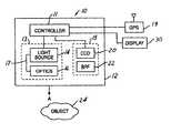
- FIG. 1is a schematic block diagram of a night vision system in accordance with one embodiment of the present invention.
- FIG. 2is a schematic diagram of a vehicle operating environment in which the present invention may be used to advantage.
- FIG. 3is a graph showing the timing of the night vision signals for the vehicles of FIG. 2 in accordance with the present invention.
- FIG. 4is a logic flow diagram of one method of operating the night vision system according to the present invention.
- FIG. 1illustrates a night vision system 10 for detecting objects at relatively low visibility light levels.
- the system 10may be utilized in a plurality of applications.
- the system 10may be used in an automotive vehicle to allow a driver to see objects at night that would not be otherwise visible to the naked eye.
- the system 10includes a controller 11 , an illumination subsystem 13 , a receiver 15 , and a GPS module 19 .
- Several of the system componentsmay be included within a housing 12 . It should be understood, however, that the components of system 10 containing housing 12 could be disposed at different locations within the vehicle wherein the housing 12 would not be needed.
- Housing 12is provided to enclose and protect the various components of the system 10 .
- Housing 12may be constructed from a plurality of materials including metals and plastics.
- system 10may be used to detect any reflective object, such as object 24 , in operative proximity to the system 10 .
- the controller 11is preferably a microprocessor-based controller including drive electronics for the illumination subsystem 13 and receiver 15 , and image processing logic for the display system 30 . Controller 11 may also process signals from GPS module 19 to generate vehicle directional and positional data. Alternatively, GPS module 19 and display unit 30 may include their own respective control logic for generating GPS data and rendering image data, respectively.
- the illumination subsystem 13includes a NIR light source 14 , beam-forming optics 16 , and a coupler 17 between the two.
- the light source 14is a NIR diode laser
- the beam forming optics 16are comprised of a thin-sheet optical element followed by a holographic diffuser, whose combined purpose is to form a beam pattern in the direction of arrow A comparable to the high-beam pattern used for normal vehicle headlamps
- the coupler 17 between themis a fiber-optic cable.
- the thin-sheet optical element described thereinis preferably constructed from a transparent, solid piece of plastic such as polycarbonate and utilizes the principal of total internal reflection to reflect light.
- the element 16may also be constructed from other transparent materials such as acrylics.
- the emitted lightenters the element as collimated light and propagates towards a plurality of reflective facets within the element.
- a second plurality of reflective facetsreceive the light reflected from the first plurality of facets and further reflect light through the front surface of the element generally in the direction of arrow A.
- the holographic diffuserreceives infrared light emitted from the thin-sheet optical element and spreads the light over the desired field of view.
- the illumination subsystemilluminates the driving environment without blinding drivers in approaching vehicles, since the NIR light is not visible to the human eye.
- Alternate light sourcesmay comprise a NIR diode laser or light-emitting diode, or any other NIR source that can be switched on and off at frequencies at or exceeding typical video frame rates (30-60 Hz).
- the light source 14is a single stripe diode laser, model number S-81-3000-C-200-H manufactured by Coherent, Inc. of Santa Clara, Calif.
- the coupler 17may be a fiber-optic cable, in which case, the NIR light source may be connected to a first end of the fiber-optic cable using a light coupler (not shown) as known by those skilled in the art.
- a second end of the fiber-optic cableis operatively disposed adjacent to a thin-sheet optical element.
- the light sourcecould be directly coupled to the thin-sheet optical element through a rigid connector, in which case the coupler would be a simple lens or reflective component.
- the system 10preferably utilizes an NIR laser light source, an alternate embodiment of system 10 may utilize a conventional light emitting diode NIR source, in lieu of the infrared diode laser.
- the receiver 15includes a NIR-sensitive camera 20 and optical band pass filter 22 .
- the NIR-sensitive camera 20provides a video signal responsive to reflected infrared light received by the camera 20 .
- the camera 20may comprise a CCD camera or a CMOS camera.
- the CCD camerais camera model number STC-H720 manufactured by Sentech Sensor Technologies America, Inc.
- Infrared light emitted from the illumination subsystem 13 and reflected off the object 24 and the environmentis received by the NIR-sensitive camera 20 .
- the video signalis transmitted to the controller 11 or directly to the display module 30 where it is processed and displayed to allow the vehicle operator to see the object 24 .
- the display 30may be a television monitor, a CRT, LCD, or heads up display positioned within the automotive vehicle to allow the user to see objects illuminated by the system 10 .
- the optical band pass filter 22is provided to filter the infrared light reflected from the object 24 .
- the filter 22only allows light within the NIR light spectrum to be received by the camera 20 .
- the filter 22allows a maximum transmission of light at a wavelength equal to the wavelength of light generated by the NIR light source 14 .
- An advantage of using the filter 22is that the filter 22 prevents saturation of the pixel elements (i.e., blooming) in the camera 20 by visible light emitted from the headlamps of other automotive vehicles.
- the filter 22is preferably disposed proximate to a receiving lens in the camera 20 .
- the GPS module 19is a conventional GPS receiver used to provide vehicle location and directional data as well as timing signals based upon the GPS satellite network.
- GPS positioning technologyis generally available as a public service for precise location and tracking objects located anywhere on the surface of the earth.
- GPSoperates by transmitting precisely timed ranging signals from earth orbiting satellites, which signals are received by ground-based receivers that, in turn, calculate precise global locations using triangulation methods. Calculations are based on measured distances to multiple earth orbiting GPS satellites. GPS makes use of very accurate atomic clocks and precisely known earth orbits for individual satellites to make such precise position calculations.
- Multi-channel GPS receiversmay be used in vehicles to simultaneously track and determine ranges for multiple satellites to enhance real time location calculation times.
- the vehicle directional datai.e., north, south, east and west, and the GPS timing signal are used to gate the illumination subsystem 13 and receiver 15 on and off to avoid blinding the receiver 15 with a similar illuminating device on an oncoming vehicle.
- the vehicle directional datamay alternatively be provided by an electronic compass within the vehicle.
- FIG. 2there is shown a vehicle operating environment wherein the present invention may be used to advantage.
- two vehicles 50 , 52are shown approaching one another from opposite directions. Both vehicles 50 , 52 are similarly equipped with a night vision system 10 in accordance with the present invention. From its GPS module, vehicle 50 is aware that it is traveling west and, likewise, vehicle 52 is aware that it is traveling east. If the illumination device of both vehicles 50 , 52 were simultaneously turned on, the respective receivers of both vehicles 50 , 52 would be saturated or blinded by the opposing vehicle's illumination device. In the present invention, this is avoided by gating the illumination device and receiver of the respective vehicles on and off as a function of the vehicle directional heading.
- FIG. 3is a graph of the gated operation of the night vision systems of the vehicles 50 , 52 of FIG. 2 in accordance with the present invention.
- the operation of night vision system of vehicle 50is shown in line 60 while the operation of the night vision system of vehicle 52 is shown as line 62 .
- the timing of the on pulses for the respective vehiclesis out-of-phase by 180°.
- the light source of vehicle 50is on when the light source of vehicle 52 is off and the light source of vehicle 52 is on when the light source of vehicle 50 is off.
- the gating signals of the respective vehicle night vision systemsare sequenced in this fashion based on the commonly received GPS timing signal.
- the time-stamp from which the vision system gating occursis synchronized in vehicles 50 , 52 because they both receive the identical time stamp from their respective GPS modules.
- the light source for vehicle 52will be gated on for a duration d.
- the light source for vehicle 52will be off and the light source for vehicle 50 traveling in the western direction will be gated on for a similar duration d.
- each respective vehicle's night vision systemcan approach 50% without interfering with the other vehicle's reception.
- the duty cycle of each vehicle's respective night vision systemis less than 50% to ensure that oppositely traveling, similarly equipped vehicles do not interfere with each other's night vision perception.
- vehicles traveling in a northbound directionwould have the gate sequence of their night vision system such that it is 180° out-of-phase with the gating sequence of the same night vision system traveling in the southbound direction.
- the northbound and southbound gating sequencemay be the same as the eastbound and westbound gating sequence to maximize the duty cycle of the night vision system, or each respective direction may be assigned a gating sequence corresponding to a 25% duty cycle or less such that the night vision system of a vehicle traveling in any one direction would not be affected by the night vision system of a vehicle traveling in any of the other directions.
- the camera system of each vehicleis gated substantially simultaneously such that it detects only light reflected from the light source of the same night vision system.
- One advantage of the present inventionis that there is no need for vehicle 50 to detect vehicle 52 to mitigate saturation of the night vision system of vehicle 50 . Because vehicle 50 is traveling in an opposite direction of vehicle 52 , their respective night vision systems will be out-of-phase with each other and camera blinding by the opposing vehicle's night vision system is thereby avoided.
- step 100by determining the vehicle heading direction. This is generated as a function of the GPS vehicle positioning data or GPS vehicle directional data, or may be determined from a compass provided as part of or separate from the GPS module or night vision system.
- step 102a time-stamp from the GPS module 19 is generated. Since the signal is generated by the GPS satellite network are commonly received by all GPS-equipped vehicles, the timing signal received by all GPS-equipped vehicles is synchronized.
- step 104the controller 11 gates on and off the illumination device 13 and receiver 15 as a function of the vehicle direction and time-stamp signal.
- a vehicle-directional-dependent phase delay from the common timing signalis provided such that similarly equipped vehicles traveling in opposite directions have their respective night vision systems gated out-of-phase with one another as shown in FIG. 3 .
- night vision systems of vehicles traveling north or westcan have a duty cycle of 50% or less and a 0° phase angle with respect to the time-stamp
- the night vision system of vehicles traveling south or eastcan have a 50% duty cycle or less with a phase angle of 180° with respect to the timing signal.
- each directioncan correspond to a 25% duty cycle or less in 90° increment phase angles.
- northmay correspond with a phase angle of 0°, east with a phase angle of 90°, south with a phase angle of 180°, and west with a phase angle of 270°.
- opposite directionsare 180° out-of-phase with each other.
- Intermediate directionsi.e., northeast, southeast, southwest, and northwest, can be likewise scaled such that opposing points are 180° out-of-phase with each other.
- northeastmay correspond with a 45° phase angle
- southwestmay correspond with a phase angle of 225°, and so on.
- step 106if an object is illuminated by the illumination subsystem 14 , the reflected light is received by the camera 20 and processed in step 108 to generate a video image, which can then be displayed to the vehicle operator.
Landscapes
- Physics & Mathematics (AREA)
- Engineering & Computer Science (AREA)
- Radar, Positioning & Navigation (AREA)
- Remote Sensing (AREA)
- General Physics & Mathematics (AREA)
- Computer Networks & Wireless Communication (AREA)
- Astronomy & Astrophysics (AREA)
- Optics & Photonics (AREA)
- Studio Devices (AREA)
- Traffic Control Systems (AREA)
- Closed-Circuit Television Systems (AREA)
Abstract
Description
Claims (20)
Priority Applications (1)
| Application Number | Priority Date | Filing Date | Title |
|---|---|---|---|
| US09/683,840US6690017B2 (en) | 2002-02-21 | 2002-02-21 | GPS-based anti-blinding system for active night vision |
Applications Claiming Priority (1)
| Application Number | Priority Date | Filing Date | Title |
|---|---|---|---|
| US09/683,840US6690017B2 (en) | 2002-02-21 | 2002-02-21 | GPS-based anti-blinding system for active night vision |
Publications (2)
| Publication Number | Publication Date |
|---|---|
| US20030155514A1 US20030155514A1 (en) | 2003-08-21 |
| US6690017B2true US6690017B2 (en) | 2004-02-10 |
Family
ID=27734956
Family Applications (1)
| Application Number | Title | Priority Date | Filing Date |
|---|---|---|---|
| US09/683,840Expired - LifetimeUS6690017B2 (en) | 2002-02-21 | 2002-02-21 | GPS-based anti-blinding system for active night vision |
Country Status (1)
| Country | Link |
|---|---|
| US (1) | US6690017B2 (en) |
Cited By (9)
| Publication number | Priority date | Publication date | Assignee | Title |
|---|---|---|---|---|
| US20020191388A1 (en)* | 2001-06-05 | 2002-12-19 | Oleg Matveev | Device and method for vehicular invisible road illumination and imaging |
| US20050134440A1 (en)* | 1997-10-22 | 2005-06-23 | Intelligent Technolgies Int'l, Inc. | Method and system for detecting objects external to a vehicle |
| US20080140318A1 (en)* | 1997-10-22 | 2008-06-12 | Intelligent Technologies International, Inc. | Weather Monitoring Techniques |
| US20080167819A1 (en)* | 1997-10-22 | 2008-07-10 | Intelligent Technologies International, Inc. | Vehicular Environment Scanning Techniques |
| DE102010044554A1 (en)* | 2010-09-07 | 2012-03-08 | Valeo Schalter Und Sensoren Gmbh | Method for detecting i.e. LED in motor car, involves synchronizing drive signals for imaging device with signals for illumination device such that imaging device produces images of vehicle environment in bright phases of illumination device |
| US8369967B2 (en) | 1999-02-01 | 2013-02-05 | Hoffberg Steven M | Alarm system controller and a method for controlling an alarm system |
| US8892495B2 (en) | 1991-12-23 | 2014-11-18 | Blanding Hovenweep, Llc | Adaptive pattern recognition based controller apparatus and method and human-interface therefore |
| US20170057435A1 (en)* | 2015-08-27 | 2017-03-02 | Renesas Electronics Corporation | Control system |
| US10361802B1 (en) | 1999-02-01 | 2019-07-23 | Blanding Hovenweep, Llc | Adaptive pattern recognition based control system and method |
Families Citing this family (4)
| Publication number | Priority date | Publication date | Assignee | Title |
|---|---|---|---|---|
| DE10305010B4 (en)* | 2003-02-07 | 2012-06-28 | Robert Bosch Gmbh | Apparatus and method for image formation |
| DE10354714B4 (en)* | 2003-11-22 | 2007-10-04 | Audi Ag | Vehicle headlight and method for operating a vehicle headlight |
| WO2008068535A1 (en)* | 2006-12-06 | 2008-06-12 | Sinisa Milnersic | Improving the night vision lighting system for use in vehicles |
| US9121944B2 (en)* | 2013-04-26 | 2015-09-01 | Panasonic Automotive Systems Company Of America, Division Of Panasonic Corporation Of North America | Mid-infrared vehicle early warning system |
Citations (10)
| Publication number | Priority date | Publication date | Assignee | Title |
|---|---|---|---|---|
| US5210586A (en) | 1990-06-27 | 1993-05-11 | Siemens Aktiengesellschaft | Arrangement for recognizing obstacles for pilots of low-flying aircraft |
| US5231401A (en) | 1990-08-10 | 1993-07-27 | Kaman Aerospace Corporation | Imaging lidar system |
| US5457639A (en) | 1991-10-11 | 1995-10-10 | Kaman Aerospace Corporation | Imaging lidar system for shallow and coastal water |
| US5519209A (en) | 1994-06-15 | 1996-05-21 | Alliedsignal Inc. | High range resolution active imaging system using a high speed shutter and a light pulse having a sharp edge |
| DE19644565A1 (en)* | 1996-10-26 | 1998-04-30 | Teves Gmbh Alfred | Safety system for moving object esp. vehicle |
| US5983161A (en) | 1993-08-11 | 1999-11-09 | Lemelson; Jerome H. | GPS vehicle collision avoidance warning and control system and method |
| US6141432A (en) | 1992-05-05 | 2000-10-31 | Automotive Technologies International, Inc. | Optical identification |
| US6236520B1 (en) | 1997-03-07 | 2001-05-22 | Daimlerchrysler Ag | Lighting device for picture recording |
| US6429429B1 (en)* | 2000-06-22 | 2002-08-06 | Ford Global Technologies, Inc. | Night vision system utilizing a diode laser illumination module and a method related thereto |
| US20020191388A1 (en)* | 2001-06-05 | 2002-12-19 | Oleg Matveev | Device and method for vehicular invisible road illumination and imaging |
- 2002
- 2002-02-21USUS09/683,840patent/US6690017B2/ennot_activeExpired - Lifetime
Patent Citations (10)
| Publication number | Priority date | Publication date | Assignee | Title |
|---|---|---|---|---|
| US5210586A (en) | 1990-06-27 | 1993-05-11 | Siemens Aktiengesellschaft | Arrangement for recognizing obstacles for pilots of low-flying aircraft |
| US5231401A (en) | 1990-08-10 | 1993-07-27 | Kaman Aerospace Corporation | Imaging lidar system |
| US5457639A (en) | 1991-10-11 | 1995-10-10 | Kaman Aerospace Corporation | Imaging lidar system for shallow and coastal water |
| US6141432A (en) | 1992-05-05 | 2000-10-31 | Automotive Technologies International, Inc. | Optical identification |
| US5983161A (en) | 1993-08-11 | 1999-11-09 | Lemelson; Jerome H. | GPS vehicle collision avoidance warning and control system and method |
| US5519209A (en) | 1994-06-15 | 1996-05-21 | Alliedsignal Inc. | High range resolution active imaging system using a high speed shutter and a light pulse having a sharp edge |
| DE19644565A1 (en)* | 1996-10-26 | 1998-04-30 | Teves Gmbh Alfred | Safety system for moving object esp. vehicle |
| US6236520B1 (en) | 1997-03-07 | 2001-05-22 | Daimlerchrysler Ag | Lighting device for picture recording |
| US6429429B1 (en)* | 2000-06-22 | 2002-08-06 | Ford Global Technologies, Inc. | Night vision system utilizing a diode laser illumination module and a method related thereto |
| US20020191388A1 (en)* | 2001-06-05 | 2002-12-19 | Oleg Matveev | Device and method for vehicular invisible road illumination and imaging |
Cited By (14)
| Publication number | Priority date | Publication date | Assignee | Title |
|---|---|---|---|---|
| US8892495B2 (en) | 1991-12-23 | 2014-11-18 | Blanding Hovenweep, Llc | Adaptive pattern recognition based controller apparatus and method and human-interface therefore |
| US20080140318A1 (en)* | 1997-10-22 | 2008-06-12 | Intelligent Technologies International, Inc. | Weather Monitoring Techniques |
| US7202776B2 (en) | 1997-10-22 | 2007-04-10 | Intelligent Technologies International, Inc. | Method and system for detecting objects external to a vehicle |
| US20080167819A1 (en)* | 1997-10-22 | 2008-07-10 | Intelligent Technologies International, Inc. | Vehicular Environment Scanning Techniques |
| US7983802B2 (en) | 1997-10-22 | 2011-07-19 | Intelligent Technologies International, Inc. | Vehicular environment scanning techniques |
| US8060308B2 (en) | 1997-10-22 | 2011-11-15 | Intelligent Technologies International, Inc. | Weather monitoring techniques |
| US20050134440A1 (en)* | 1997-10-22 | 2005-06-23 | Intelligent Technolgies Int'l, Inc. | Method and system for detecting objects external to a vehicle |
| US8369967B2 (en) | 1999-02-01 | 2013-02-05 | Hoffberg Steven M | Alarm system controller and a method for controlling an alarm system |
| US9535563B2 (en) | 1999-02-01 | 2017-01-03 | Blanding Hovenweep, Llc | Internet appliance system and method |
| US10361802B1 (en) | 1999-02-01 | 2019-07-23 | Blanding Hovenweep, Llc | Adaptive pattern recognition based control system and method |
| US20020191388A1 (en)* | 2001-06-05 | 2002-12-19 | Oleg Matveev | Device and method for vehicular invisible road illumination and imaging |
| DE102010044554A1 (en)* | 2010-09-07 | 2012-03-08 | Valeo Schalter Und Sensoren Gmbh | Method for detecting i.e. LED in motor car, involves synchronizing drive signals for imaging device with signals for illumination device such that imaging device produces images of vehicle environment in bright phases of illumination device |
| US20170057435A1 (en)* | 2015-08-27 | 2017-03-02 | Renesas Electronics Corporation | Control system |
| US9969387B2 (en)* | 2015-08-27 | 2018-05-15 | Renesas Electronics Corporation | Control system |
Also Published As
| Publication number | Publication date |
|---|---|
| US20030155514A1 (en) | 2003-08-21 |
Similar Documents
| Publication | Publication Date | Title |
|---|---|---|
| US6690017B2 (en) | GPS-based anti-blinding system for active night vision | |
| US6828544B2 (en) | Active night vision system for vehicles employing anti-blinding scheme | |
| US6774367B2 (en) | Active night vision system for vehicles employing anti-blinding scheme | |
| CN100565273C (en) | Vehicle anti-glare system | |
| US6967569B2 (en) | Active night vision with adaptive imaging | |
| EP0830267B1 (en) | Rearview vision system for vehicle including panoramic view | |
| US7319805B2 (en) | Active night vision image intensity balancing system | |
| US6498620B2 (en) | Vision system for a vehicle including an image capture device and a display system having a long focal length | |
| US8842176B2 (en) | Automatic vehicle exterior light control | |
| US6379009B1 (en) | Conjugate optics projection display with image enhancement | |
| EP1562063B1 (en) | Night Vision System | |
| US20030155513A1 (en) | Active night vision system for vehicles employing short-pulse laser illumination and a gated camera for image capture | |
| US20120081544A1 (en) | Image Acquisition Unit, Acquisition Method, and Associated Control Unit | |
| US10323812B2 (en) | Intelligent automotive headlamp module with combined functions | |
| US6966681B2 (en) | Active night vision system for vehicles employing anti-blinding scheme | |
| WO2003077012A3 (en) | Electro-optic lens with integrated components | |
| EP1515162A1 (en) | Device for detecting optical and optoelectronic objects | |
| JP2003203294A (en) | Method for improving view in vehicles | |
| JP7726902B2 (en) | In-vehicle camera control device | |
| US9573444B2 (en) | Automobile and anti-dazzling method for automobiles | |
| US20130083195A1 (en) | Polarization-based anti-blinding night vision system, vehicle comprising same, and method therefor |
Legal Events
| Date | Code | Title | Description |
|---|---|---|---|
| AS | Assignment | Owner name:FORD MOTOR COMPANY, MICHIGAN Free format text:ASSIGNMENT OF ASSIGNORS INTEREST;ASSIGNORS:REMILLARD, JEFFREY THOMAS;WEBER, WILLES H.;REEL/FRAME:012412/0140 Effective date:20020219 Owner name:FORD GLOBAL TECHNOLOGIES, INC., MICHIGAN Free format text:ASSIGNMENT OF ASSIGNORS INTEREST;ASSIGNOR:FORD MOTOR COMPANY;REEL/FRAME:012412/0162 Effective date:20020220 | |
| AS | Assignment | Owner name:FORD GLOBAL TECHNOLOGIES, LLC, MICHIGAN Free format text:MERGER;ASSIGNOR:FORD GLOBAL TECHNOLOGIES, INC.;REEL/FRAME:013987/0838 Effective date:20030301 Owner name:FORD GLOBAL TECHNOLOGIES, LLC,MICHIGAN Free format text:MERGER;ASSIGNOR:FORD GLOBAL TECHNOLOGIES, INC.;REEL/FRAME:013987/0838 Effective date:20030301 | |
| STCF | Information on status: patent grant | Free format text:PATENTED CASE | |
| FPAY | Fee payment | Year of fee payment:4 | |
| FPAY | Fee payment | Year of fee payment:8 | |
| FPAY | Fee payment | Year of fee payment:12 |