US6689966B2 - System and method for determining positional information - Google Patents
System and method for determining positional informationDownload PDFInfo
- Publication number
- US6689966B2 US6689966B2US09/812,900US81290001AUS6689966B2US 6689966 B2US6689966 B2US 6689966B2US 81290001 AUS81290001 AUS 81290001AUS 6689966 B2US6689966 B2US 6689966B2
- Authority
- US
- United States
- Prior art keywords
- marking
- coordinate
- symbol
- symbols
- coding pattern
- Prior art date
- Legal status (The legal status is an assumption and is not a legal conclusion. Google has not performed a legal analysis and makes no representation as to the accuracy of the status listed.)
- Expired - Fee Related, expires
Links
Images


Classifications
- G—PHYSICS
- G06—COMPUTING OR CALCULATING; COUNTING
- G06F—ELECTRIC DIGITAL DATA PROCESSING
- G06F3/00—Input arrangements for transferring data to be processed into a form capable of being handled by the computer; Output arrangements for transferring data from processing unit to output unit, e.g. interface arrangements
- G06F3/01—Input arrangements or combined input and output arrangements for interaction between user and computer
- G06F3/03—Arrangements for converting the position or the displacement of a member into a coded form
- G06F3/033—Pointing devices displaced or positioned by the user, e.g. mice, trackballs, pens or joysticks; Accessories therefor
- G06F3/0354—Pointing devices displaced or positioned by the user, e.g. mice, trackballs, pens or joysticks; Accessories therefor with detection of 2D relative movements between the device, or an operating part thereof, and a plane or surface, e.g. 2D mice, trackballs, pens or pucks
- G06F3/03545—Pens or stylus
- G—PHYSICS
- G06—COMPUTING OR CALCULATING; COUNTING
- G06F—ELECTRIC DIGITAL DATA PROCESSING
- G06F3/00—Input arrangements for transferring data to be processed into a form capable of being handled by the computer; Output arrangements for transferring data from processing unit to output unit, e.g. interface arrangements
- G06F3/01—Input arrangements or combined input and output arrangements for interaction between user and computer
- G06F3/03—Arrangements for converting the position or the displacement of a member into a coded form
- G06F3/0304—Detection arrangements using opto-electronic means
- G06F3/0317—Detection arrangements using opto-electronic means in co-operation with a patterned surface, e.g. absolute position or relative movement detection for an optical mouse or pen positioned with respect to a coded surface
- G06F3/0321—Detection arrangements using opto-electronic means in co-operation with a patterned surface, e.g. absolute position or relative movement detection for an optical mouse or pen positioned with respect to a coded surface by optically sensing the absolute position with respect to a regularly patterned surface forming a passive digitiser, e.g. pen optically detecting position indicative tags printed on a paper sheet
- G—PHYSICS
- G06—COMPUTING OR CALCULATING; COUNTING
- G06K—GRAPHICAL DATA READING; PRESENTATION OF DATA; RECORD CARRIERS; HANDLING RECORD CARRIERS
- G06K1/00—Methods or arrangements for marking the record carrier in digital fashion
- G06K1/12—Methods or arrangements for marking the record carrier in digital fashion otherwise than by punching
- G06K1/121—Methods or arrangements for marking the record carrier in digital fashion otherwise than by punching by printing code marks
- G—PHYSICS
- G06—COMPUTING OR CALCULATING; COUNTING
- G06V—IMAGE OR VIDEO RECOGNITION OR UNDERSTANDING
- G06V10/00—Arrangements for image or video recognition or understanding
- G06V10/10—Image acquisition
- G06V10/17—Image acquisition using hand-held instruments
- G—PHYSICS
- G06—COMPUTING OR CALCULATING; COUNTING
- G06V—IMAGE OR VIDEO RECOGNITION OR UNDERSTANDING
- G06V10/00—Arrangements for image or video recognition or understanding
- G06V10/10—Image acquisition
- G06V10/19—Image acquisition by sensing codes defining pattern positions
Definitions
- the present inventionrelates to pattern recognition and specifically relates to devices and methods relating to surfaces having a coding pattern available for analysis.
- U.S. Pat. No. 5,852,434discloses a device for determining an absolute position.
- the deviceincludes a writing surface having a position-coding pattern used to determine X/Y coordinates, a detector for detecting the position-coding pattern and a processor for determining the position of the detector in relation to the writing surface based on the detected position-coding pattern.
- the devicemakes it possible for a user to input handwritten and hand-drawn information into a computer at the same time as the information is written/drawn on the writing surface.
- a number of examples of position codingare given in U.S. Pat. No. 5,852,434.
- the first exampleshows symbols built up of three concentric circles, with the outermost circle representing the x-coordinate and the middle one representing the y-coordinate.
- the two outermost circlesare further divided into 16 parts that specify different numbers depending on their fill pattern.
- Each pair of x/y coordinatesis coded with a complex symbol having a special appearance.
- the coordinates at every point on the writing surfaceare identified with the aid of a bar code, a bar code for the x-coordinate being specified above a bar code for the y-coordinate.
- Devices in the prior art used for this type of detectionare generally constructed to register four symbols at the same time ensuring a reliably capture of at least one symbol in its totality. This capture is necessary for the device to perform the position determination.
- the prior art summarized abovedoes not disclose, for example, a computer program used in cooperation with an input device to perform calculations related to the position determination because generally only position information is processed.
- the prior arthas further shortcomings because the patterns used are built up of complex symbols, the information content of that indicates the actual positions. The smaller these symbols are the more difficult it becomes to produce the patterned writing surface, while increasing the risk of erroneous position determinations. On the other hand, the use of larger the symbols decreases the position resolution.
- Systems and methods consistent with the present inventionmay have coding patterns with a number of spatial levels and utilizing the spatial levels.
- the inventionrelates to a product that has a surface that is provided with a coding pattern that comprises symbols that have at least two different values.
- the inventionis characterized in that each symbol comprises a raster point and at least one marking, that the raster point is included in a raster which extends over the surface; that the value of each symbol is indicated by the location of said marking in relation to a raster point and that at least one marking comprises marking information.
- each positionis coded with a complex symbol, the complete information content of which is needed for specifying position information.
- a symbolis used the value of which is specified by the location of a marking in relation to a raster point. There is thus one type of symbol for each value.
- a device which will carry out the position determinationtherefore only needs to detect the occurrence of one marking.
- a position-determining devicecan distinguish between different markings and thereby acquire further information related to, for example, the position in question. This further marking information can advantageously vary depending on the position that is determined.
- the design of the symbol according to the inventionalso entails that a surface which is provided with a coding pattern according to the invention becomes more aesthetically pleasing.
- each positionis coded with a single symbol that therefore must be rather complex.
- each positioncan be coded with a plurality of symbols. Each individual symbol can thus be made less complex and thus simpler to detect with higher reliability.
- the position information and position-related informationare separated in that the markings of the symbols contain different types of information depending on which spatial resolution is taken into consideration.
- a first spatial resolution levelthe markings of the symbols are only used for specifying position information.
- the further informationcan be coded and retrieved from the markings.
- each positionis coded with a symbol that is “isolated” from symbols of the surrounding positions.
- the position resolutionis thus limited by the surface occupied by the symbol of a position.
- the position-coding pattern according to the inventioncan be built up in corresponding manner, each position being coded by an “isolated” group of symbols.
- each symbolcontributes to the coding of more than one position. In this manner, a “floating” transition between different positions is obtained.
- each positionis coded partly by the same symbols as the adjoining positions.
- the floating codingis advantageous since it makes it possible to increase the position resolution. Furthermore, it is possible to reduce the relationship between, on the one hand, the number of symbols which a position-determining device must register in order to be able to carry out a position determination reliably and, on the other hand, the number of symbols which code a position.
- each symbolcontributes to the coding of both a first and a second position coordinate.
- the coordinate systemcan be suitably Cartesian but other types of coordinate systems are also conceivable.
- each symbolcan be advantageously translatable into at least a first digit which is used for coding the first coordinate, and at least a second digit which is used for coding the second coordinate, the symbols in the position-coding pattern together representing a first position code for the first coordinate and a second position code for the second coordinate.
- the two coordinatescan then be coded independently of one another, which makes the coding simpler when the coding is “floating”.
- the value of the symbolis represented in a binary manner, a first bit being used for the coding of a first coordinate and a second bit for the coding of a second coordinate.
- the position-coding patternis advantageously based on a first cyclic, preferably binary, number series which has the characteristic that no sequence with a first predetermined number of digits appears more than once in the number series. Due to the fact that the position-coding pattern is built up in this manner, it will contain inherent information about the positions so that the coordinates can be calculated according to predetermined rules. This is advantageous in that it means that the decoding of the position-coding pattern can be implemented in an efficient manner in, for example, software. Besides, it will be much simpler to produce the position-coding pattern in this way compared with trying to randomly generate an unambiguous position-coding pattern of a floating type.
- the productcan comprise a plurality of writing surfaces each of which comprises the position-coding pattern with the further marking information coded in a number of markings.
- the productcan consist of a notepad with a plurality of sheets, such as maps, forms, blanks etc.
- the position-coding patternsthen differ for the various writing surfaces by the sequence in the cyclic number series with which a predetermined column or row begins.
- the “same” patterncan thus be used for a plurality of writing surfaces which can be separated or integrated with one another by allowing, for example, the first column to begin at different positions in the number series.
- the position-coding patterncan be implemented with any parameter whatever that can be used for producing symbols of the above-mentioned type which can be detected by a detector.
- the parametercan be electric or chemical or of another type.
- the position-coding patternis preferably optically readable which makes it simpler to apply it to the surface. The pattern should thus be able to reflect or absorb light but the light does not need to lie within the visible range.
- the raster and/or the raster pointscan be implemented on the surface. In a preferred embodiment, however, the raster and the raster points are virtual. Thus, the raster is not marked on the surface at all but only constitutes an imaginary raster which forms the base of the coding but which can be located on the basis of the location of the markings.
- the products described abovecan be any products whatever that have a surface with a coding pattern. They can be used for a large number of different applications. For example, they can be used for continuously registering the position of a pen which is conducted over the writing surface where the further position-related marking information, for example, contains direct information about how the written text is to be reproduced, for example on a computer screen. Further examples comprise a map with a printed pattern according to the invention, whereby, for example, the further information in the markings can contain information relating, for example, levels of elevation. They can also be used in determining the position of a tool, an instrument or the like. They can also be used as a mouse pad. A person skilled in the art can think of many other applications.
- a computer programfor determining the position of a partial surface on a surface, which is provided with a position-coding pattern which comprises a plurality of symbols, on the basis of an image of the partial surface, each symbol comprising a raster point and at least one marking
- the computer programbeing stored on a storage medium which can be read by a computer and which comprises instructions for causing the computer to locate a predetermined plurality of symbols in the image, to determine the value of each of the said predetermined plurality of symbols, to separate the position-coding pattern in the image into a first position code for a first coordinate and a second position code for a second coordinate by translating the value of each symbol into at least a first digit for the first position code and at least a second digit for the second position code, and to calculate the first coordinate with the aid of the first position code and the second coordinate with the aid of the second position code.
- the locating of at least one markingis carried out, which comprises marking information, after which this is interpreted.
- the computer programscan be used together with prior-art position-determining devices. They can be installed in a separate computer to which images of the position-coding pattern are sent, or in the actual device that registers the position-coding pattern.
- a device for position determinationcomprising a sensor for producing an image of a partial surface on a surface and image-processing devices which are arranged to decode a position-coding pattern on a product the surface being a surface on the product, which surface is provided with the position-coding pattern.
- systems and methods consistent with the present inventionmay employ a principle surface with a coding pattern that may include symbols having at least two different values.
- Each symbolmay include a raster point and at least one marking.
- the raster pointmay be included in a raster extending over the surface, and the value of each symbol may be indicated by the location of the marking in relation to a raster point.
- the markingmay include marking information.
- Another aspect of the inventionmay employ a program stored on a computer-readable medium for determining the position of a partial surface on a surface having a position-coding pattern that includes a plurality of symbols, with each symbol including a raster point and at least one marking.
- the programmay include instructions for locating a predetermined plurality of symbols in an image of the partial surface, determining the value of each said predetermined plurality of symbols, separating the position-coding pattern into a first position code for a first coordinate of the partial surface and a second position code for a second coordinate of the partial surface by translating the value of each symbol into at least a first digit for the first position code and at least a second digit for the second position code.
- the program instructionmay further calculate the first coordinate using the first position code and the second coordinate using the second position code, calculate the value of each symbol by determining the location of each marking in relation to the raster point; locate at least one marking having marking information; and interpret the marking information.
- a systemmay include a sensor configured to produce an image of a partial surface of a plurality of partial surfaces on a principle surface, the partial surface including a position-coding pattern.
- the systemfurther may include an image-processing element configured to locate a predetermined plurality of symbols in the image, with each symbol including at least one marking.
- the image processing elementmay also be configured to determine the value of each of the predetermined plurality of symbols, separate the position-coding pattern in the image into a first position code for a first coordinate for the partial surface and into a second position code for a second coordinate for the partial surface by translating the value of each symbol into at least a first digit for the first code and at least a second digit for the second code, calculate the first coordinate using the first position code and the second coordinate using the second position code, locate at least one marking which comprises marking information and interpret the marking information.
- the image-processing elementmay be in wireless, optical, or direct communication with the sensor.
- the capability of interpreting the further information at different spatial resolutionswill prove very advantageous in a commercial sense.
- Devices for interpreting the position information and further information of any spatial resolutionare envisaged, but also devices capable of interpreting only position information and further information at only one other spatial resolution (or even no other spatial resolution than that of the position information).
- Such separation of devices into different levels of capabilitymay be utilized commercially in that several generations of devices may be developed, each being capable of interpreting further information at further spatial resolutions.
- Backward compatibilitywill be inherent in that the capability for early generation devices capable of interpreting information at, e.g., one or two spatial resolutions will also be able to interpret the information of the first one or two spatial resolutions from symbols having information at three or more spatial resolutions.
- One general advantage of the present inventionis the fact that a number of different spatial resolution levels can be used. Reading devices such as reading pens can be provided with different capacity for reading and decoding position information and marking information. For example, a simple and inexpensive reader can be produced for simply reading the pattern at the lowest spatial resolution level whilst a more advanced and more expensive reader can be produced for reading information at a number of spatial resolution levels.
- FIG. 1schematically shows an embodiment of a product according to the present invention which is provided with a position-coding pattern
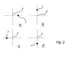
- FIGS. 2 a - 2 dschematically show how the symbols can be configured in an embodiment of the invention
- FIG. 3schematically shows an example of 4 ⁇ 4 symbols which maybe used for coding a position
- FIG. 4schematically shows a device according to the present invention which can be used for position determination
- FIGS. 5 a - 5 dshow examples of symbols with markings containing further binary-coded information at a number of spatial resolution levels.
- position information and position-related informationmay be separated in that the markings of the symbols contain different types of information depending on which spatial resolution may be taken into consideration.
- a first spatial resolution levelthe markings of the symbols are only used for specifying position information.
- further spatial resolution levelsthat are higher than the first one, further information can be coded and retrieved from the markings.
- Symbols used with systems and methods consistent with the present inventioncan be employed for coding any type of information but are advantageously used for coding positions and position-related further information via the markings of the symbols.
- positionsmay be coded with a single symbol, which therefore must be rather complex.
- each positionmay be coded with a plurality of symbols. Each individual symbol can thus be made less complex and thus simpler to detect with higher reliability.
- a symbolmay be used and the value may be specified by the location of a marking in relation to a raster point. There may be one type of symbol for each value.
- the raster and/or the raster pointscan be implemented on the surface. In a preferred embodiment, however, the raster and the raster points may be virtual. Thus, the raster may not be marked on the surface at all but may only constitute an imaginary raster that forms the base of the coding but which can be located on the basis of the location of the markings.
- a deviceperforming position determination therefore may only need to detect the occurrence of one marking.
- a position-determining devicecan distinguish between different markings and thereby acquire further information related to, for example, the position in question. This further marking information can advantageously vary depending on the position determined.
- the devicemay be implemented as an independent unit, or alternative, the sensor can be physically separated from the image-processing device.
- a personal computerfor example, could receive the registered images transferred by the sensor.
- the design of the symbol according to the inventionentails that a surface provided with a coding pattern may become more esthetically pleasing. Further, a large distance between the markings in relation to the position-information density may be made possible, allowing the coding to less sensitive to movement blur.
- positionsare coded with a symbol “isolated” from symbols of the surrounding positions.
- the position resolutionmay be thus limited by the surface occupied by the symbol of a position.
- the position-coding pattern according to the preferred embodimentcan be built up in corresponding manner, each position being coded by an “isolated” group of symbols. Further, each symbol may contribute to the coding of more than one position. In this manner, a “floating” transition between different positions may be obtained. In other words, each position may be coded partly by the same symbols as the adjoining positions.
- the floating codingmay be advantageous since it makes it possible to increase the position resolution. Furthermore, it may be possible to reduce the relationship between the number of symbols that a position-determining device must register to carry out its function reliably, on the one hand, and the number of symbols that code a position, on the other.
- each symbolmay contribute to the coding of both a first and a second position coordinate.
- different symbolsmay not be needed for the different coordinates, making the position code simpler and the position resolution better.
- the coordinate systemcan be suitably Cartesian but other types of coordinate systems are also conceivable.
- each symbolmay be translatable into a first digit used for coding the first coordinate, and a second digit used for coding the second coordinate.
- the symbols in the position-coding patterntogether representing a first position code for the first coordinate and a second position code for the second coordinate.
- the two coordinatescan then be coded independently of one another, making the coding simpler when the coding is “floating.”
- the value of the symbolmay be represented in a binary manner, a first bit being used for the coding of a first coordinate and a second bit for the coding of a second coordinate.
- the symbolmay also be translated into multiple digits, allowing for greater precision.
- the position-coding pattern of the preferred embodimentmay be advantageously based on a first cyclic, preferably binary, number series.
- This number serieshas the characteristic that no sequence with a first predetermined number of digits appears more than once in the number series. Building the position-coding pattern in this manner permits it to contain inherent information about the positions, allowing the coordinates to be calculated under predetermined rules. This may be advantageous because it allows implementation of the decoding of the position-coding pattern in an efficient manner, with software, for example. Moreover, it may be much simpler to produce the position-coding pattern in this manner than to attempt and randomly generate an unambiguous position-coding pattern of a floating type. With this general description specific aspects and various aspects of the preferred embodiments are described below.
- FIG. 1shows a part of a product in the form of a sheet of paper 1 having a principle surface 2 provided with an optically readable position-coding pattern 3 .
- position-coding pattern 3consists of symbols 4 systematically arranged over surface 2 so that it has a “patterned” appearance.
- the symbols 4include markings that, for the sake of clarity, are depicted as round in FIG. 1 .
- FIGS. 5 a and 5 ba number of other configurations of markings are shown in detail in order to illustrate how more detailed information may be represented at a higher spatial resolution level.
- the productcan include a plurality of writing surfaces each of that may include position-coding pattern 3 with the further marking information coded in a number of markings.
- the productcan consist of a notepad with a plurality of sheets, such as maps, forms, blanks etc.
- the position-coding patternsthen differ for the various writing surfaces by the sequence in the cyclic number series with which a predetermined column or row begins.
- the “same” patterncan thus be used for a plurality of writing surfaces that can be separated or integrated with one another by allowing, for example, the first column to begin at different positions in the number series.
- the products described abovecan be any products having a surface 2 with a coding pattern 3 .
- the productsmay be used in a large number of different applications. For example, they can be used for continuously registering the position of a pen that may be conducted over the writing surface.
- the further position-related marking information on the productmight contain direct information about how the written text may be reproduced such as, for example, on a computer screen.
- Further examples of products that may use the features of the present inventioncould include maps with a printed coding pattern.
- the information in the markingsmay include information relating to various geographical or topographical information, such as levels of elevation, population statistics, natural resource reserves, etc.
- the patterncould also be used to determine the position of a tool, an instrument, etc. It is contemplated that a person skilled in the art will realize many other applications.
- sheet 1may have an x-coordinate axis and a y-coordinate axis.
- position determinationcan be performed over the entire surface of the product.
- the surface containing the coding patternmay only occupy a selected area of the product.
- sheet 10can be used to produce an electronic representation of information that may be written or drawn on the surface. The electronic representation can be produced by continuously determining, while writing on the surface with a pen, the position of the pen on the sheet of paper 1 by reading the position-coding pattern.
- the position-coding patternmay include a virtual raster that is neither visible to the human eye nor can be detected directly by a device used to determine positions on the surface, and a plurality of symbols 4 each being able to assume one of four values “1”-“4” as described below.
- the position-coding pattern 3 in FIG. 1has been greatly enlarged for clarity. It is also shown only on a part of the sheet of paper 1 .
- the position-coding pattern 3may be arranged in such a manner that the position of a partial surface on the writing surface may be coded by the symbols on this partial surface. Dashed lines in FIG. 1 show a first partial surface 5 a and a second partial surface 5 b .
- the part of the position-coding pattern 3 (in this case 4 ⁇ 4 symbols) located on the first partial surface 5 acodes a first position
- the part of the position-coding pattern 3 located on the second partial surface 5 bcodes a second position.
- Position-coding pattern 3may be partially common to the adjoining first and second positions. Such a position-coding pattern 3 may be designated as “floating” in this application.
- Position-coding pattern 3can be implemented with any parameter capable of producing symbols detectable by a detector.
- the parametercan be electric or chemical or of another type.
- position-coding pattern 3may be optically detectable, making it easier to apply it to surfaces. The pattern should thus be able to reflect or absorb light but this light need not lie within the human visible range.
- FIGS. 2 a-dshow an embodiment of a symbol that may be used in the position-coding pattern according to the invention.
- the symbolmay include a virtual raster point 6 that may be represented by the intersection between the raster lines, and a marking 7 that appears as a dot.
- the value of the symboldepends on where the marking may be located. In the example in FIG. 2, there are four possible locations, one on each of the raster lines extending from the raster points. The displacement from the raster point may be equal for all values.
- the symbolhas the value 1 in FIG. 2 a , the value 2 in FIG. 2 b , the value 3 in FIG. 2 c and the value 4 in FIG. 2 d . Expressed in other words, there are four different types of symbol.
- Each symbolcan thus represent four values “1-4”.
- This means that the position-coding patterncan be divided into a first position code for the x-coordinate and a second position code for the y-coordinate. The dividing may be done in accordance with the following:
- each symbolmay be translated into a first digit, in this case a bit, for the x-code and a second digit for the y-code.
- a first digitin this case a bit
- a second digitfor the y-code.
- the patternscan be combined into a common pattern that may be coded graphically with the aid of a plurality of symbols according to FIG. 2 .
- Each positionmay be coded with the aid of a plurality of symbols.
- 4 ⁇ 4 symbolsare used for coding a position in two dimensions, i.e., an x-coordinate and a y-coordinate.
- the position codemay be built up with the aid of a number series of ones and zeroes that have the characteristic that no sequence of four bits occurs more than once in the series.
- the number seriesmay be cyclic, which means that the characteristic also applies if the end of the series may be coupled together with its beginning. Thus, a sequence of four bits always has an unambiguously determined position in the number series.
- the seriescan be maximally 16 bits long if it is to have the characteristic for sequences having four bits described above. In this example, however, only a 7-bit-long series according to the following need be used:
- This seriescontains seven unique sequences of four bits that code a position in the series according to the following:
- the number seriesmay be written sequentially in columns over the entire surface to be coded.
- the codingmay be based on the difference or position displacement between numbers in adjoining columns.
- the magnitude of the differencemay be determined by the position in the number series at which the column is allowed to begin (i.e., with which sequence). More specifically, if one takes the difference modulo 7 between, on the one hand, a number that may be coded by a four-bit sequence in a first column and which thus can have the value (position) 0-6, and, on the other hand, a corresponding number (i.e., a sequence on the same “level”) in an adjoining column, the result may be the same independently of where along the two columns the comparison may be made.
- an x-coordinatecan be coded that is constant for all y-coordinates.
- each position on the surfacemay be coded with 4 ⁇ 4 symbols in this example, three differences (having the value 0-6) are available according to the above for coding the x coordinate.
- codingmay be performed in such a manner that of the three differences, one will always have the value 1 or 2 and the other two will have the values in the interval 3-6.
- no differenceswill be zero in the x code.
- the x-codemay be constructed in such a manner that the differences, in this exemplary embodiment, will be as follows:
- Each x-coordinatemay be coded with two numbers between 3 and 6, and a subsequent numbers that may be 1 or 2. If, for example, 3 may be subtracted from the high numbers and 1 from the low one, then a number in mixed base will be obtained. This number directly provides a position in the x direction, allowing a determination of from which the x-coordinate can then be determined directly, as shown in the example below.
- the y-coordinatesmay be coded in accordance with the same principal.
- the cyclic number seriesmay be written repeatedly in horizontal rows over the surface to be position-coded. Exactly as in the case of the x-coordinates, the rows may begin at different positions, i.e., with different sequences in the number series. However, it is not the differences that are used for the y-coordinates but the coordinates are coded with numbers based on the starting position of the number series in each row.
- the x-coordinate for 4 ⁇ 4 symbolsit may be possible to determine the starting positions in the number series for the rows that are included in the y code in the 4 ⁇ 4 symbols.
- the most significant digitmay be determined by allowing this to be the only one that has a value in a specific interval.
- one row of fourbegins at position 0-1 in the number series, indicating that this row relates to the least significant digit in a y-coordinate, and the other three begin at position 2-6.
- Each y-coordinatemay therefore be coded with three numbers between 2 and 6 and a subsequent number between 0 and 1.
- the starting position of the first number series in the first columncan be calculated when the x coordinate has been determined. The seven different starting positions of the first series can code different sheets or writing surfaces on a product.
- FIG. 3shows an example of an image consistent with the present invention having 4 ⁇ 4 symbols that are read by a device for position determination.
- x codey code: 0 0 0 0 0 0 0 0 1 1 0 1 0 0 1 0 0 0 0 0 0 0 0 0 0 1 0 1 1 0 0 1 0 1 0 1 0 1 0 1 0 1 0 1 0 1 0 1 0 1 0 1 0 1 0 1 0 1 0 1 0 1 0 1 0 1 0 1 0 1 0 1 0 1 0 1 0 1 0 1 0 1 0 1 0 1 0 1 0 1 0 1 0 1 0 1 0 1 0 1 0 1 0 1 0 1 0 1 0 1 0 1 0 1 0 1 0 1 0 1 0 1 0 1 0 1 0 1 0 1 0 1 0 1 0 1 0 1 0 1 0 1 0 1 0 1 0 1 0 1 0 1 0 1 0 1 0 1
- the vertical x sequencescode the following positions in the number series: 2 0 4 6.
- the first coded x positionis position 0
- the differencelies in the interval 1-2 and which appear in the 4 ⁇ 4 symbols may be the 20th such difference.
- the position of the topmost left corner for the 4 ⁇ 4 symbol groupis (58,170).
- the numbers 0-19may be coded in mixed base and by adding together the representations for numbers 0-19 in mixed base, the total difference between these columns may be obtained.
- a primitive algorithm for doing thisis to generate these twenty numbers and directly add together their digits. The sum obtained is called s.
- the sheet or writing surfacemay then be given by (5-s) modulo 7 .
- each positionis coded with 4 ⁇ 4 symbols and a number series with 7 bits may be used.
- Positionscan be coded with more or fewer symbols.
- the number of symbolsdoes not need to be the same in both directions.
- the number seriescan have different length and does not need to be binary but may be built up on another base. Different number series can be used for coding in the x direction and coding in the y direction.
- the symbolscan have different numbers of values.
- the markingmay be a dot. Naturally, it can have a different appearance.
- the markingmay consist of a line that begins in the virtual raster point and extends from that to a predetermined position.
- the symbolsare used within a square partial surface for coding a position.
- the partial surfacecan have another form, for example, hexagonal. Neither do the symbols need to be arranged in rows and columns at an angle of 90° with respect to one another but can also be arranged in other configurations.
- the virtual rasterFor the position code to be detectable, the virtual raster must be determined. This can be done by studying the distance between different markings. The shortest distance found between two markings must originate from two adjoining symbols having the value 1 and 3 so that the markings are located on the same raster line between two raster points. When such a pair of markings has been detected, the associated raster points can be determined with knowledge of the distance between the raster points and the displacement of the markings from the raster points. Once two raster points have been located, further raster points can be determined by means of measured distances to other markings and with knowledge of the relative distance of the raster points.
- the detectorcomprises a casing 11 , which has the approximate format of a pen. At a short end of the casing there may be an opening 12 . The short end is intended to be against or be held at a short distance from the surface on which the position determination is to be performed.
- Casing 11mainly accommodates an optical part, an electronic part and a power supply.
- the optical partmay include at least one light-emitting diode 13 for illuminating the surface to be imaged and a light-sensitive area sensor 14 , for example, a CCD or CMOS sensor, to register a two-dimensional image.
- the devicemay also contain a lens system.
- the power supply for the devicemay be obtained from a battery 15 , mounted in a separate compartment in the casing 11 .
- the electronic partmay include image-processing element 16 for determining a position on the basis of the image registered by the sensor 14 .
- Image processing element 16 in this embodimentincludes a processor unit with a processor that is programmed to reading images from the sensor and perform position determination on the basis of these images.
- Image processor element 16may also, in the alternative, include a specifically designed image processor IC, digital signal processor, etc.
- the devicealso may further include a writing implement point such as a pen point 17 to write normal pigment-based writing on the surface on which the position determination is to be performed.
- a writing implement pointsuch as a pen point 17 to write normal pigment-based writing on the surface on which the position determination is to be performed.
- Pen point 17may be retracted and extended so that the user can control whether or not it is to be used. In certain applications, pen point 17 may be absent.
- the image-processor element in the devicemay be arranged to determine the position in a “rule-based” manner, the device does not require a large amount of storage capacity, which may be an advantage with respect to the manufacturing costs of the device and the possibility of producing a stand-alone unit.
- reading penscan be provided with different capacity for reading and decoding position information and marking information.
- a simple and inexpensive readermay be produced for simply reading the pattern at the lowest spatial resolution level while a more advanced and more expensive reader can be produced for reading information at a number of spatial resolution levels. Either of the aspects falls within the scope contemplated for the present invention.
- the devicemay also include buttons 180 to activate and control it.
- italso has a transceiver 190 for wireless transmission or communication, e.g., by means of IR light or radio waves, of information to and from the device.
- the devicealso includes a display 200 for showing positions or registered information.
- Applicant's international patent application WO 98/20446describes a device for registering text. This device can be used for position determination if it is programmed in a suitable manner. If it is to be used for pigment-based writing, it should also have a pen point.
- the devicecan be divided into different physical casings, a first casing containing components for obtaining images of the position-coding pattern and for transferring them to components located in a second casing and that perform the position determination on the basis of the registered image or images.
- position determinationmay be performed with a processor programmed with software for locating and decoding the symbols in an image and for determining the positions from the codes.
- a person skilled in the artcan design software that performs position determination on the basis of an image of a part of a position-coding pattern.
- a skilled personcan design software for printing the position-coding pattern on the basis of the above description.
- Computer programs of the present preferred embodimentmay be independently used with other position-determining devices. These programs may be installed in a separate computer that can receive images of the position-coding pattern, or in the actual device that registers the position-coding pattern.
- the patternis optically readable and the sensor is thus optical.
- the patterncan be based on a parameter other than an optical parameter.
- the sensormay be of a type that can read the parameter in question.
- the rasteris a grid network. It can also have other forms.
- the longest possible cyclic number serieswhich is used. This provides a certain redundancy that can be used, for example, to check the turning of the read group of symbols.
- FIGS. 5 a - 5 dshow four examples of symbols with markings that contain further binary-coded information at a number of spatial resolution levels.
- FIG. 5 ashows a marking 51 that, for example, maybe one of the markings in one of the above examples.
- the marking 51is of rectangular form and can be read at a first spatial resolution level.
- a further marking pattern 52readable at a second spatial resolution level, constitutes a part of the marking 51 and with a binary interpretation, this further pattern 52 has, for example, the binary value “10101”.
- FIG. 5 bshows, analogously to FIG. 5 a , a marking 53 at a first spatial resolution level and a further marking pattern 54 that may be readable at a second spatial resolution level, the binary value will be “1010010101001”.
- FIG. 5 cshows, analogously to FIGS. 5 a and 5 b , a marking 55 at a first spatial resolution level and two further marking patterns 56 and 57 , which are readable at a second spatial resolution level and the binary values of which are “10101” and “10101”, respectively.
- FIG. 5 dshows, analogously to FIGS. 5 a - 5 c , a marking 58 at a first spatial resolution level and two further marking patterns 59 and 60 , readable at a second spatial resolution level and the binary value of which are “10101” and, respectively, readable at a third spatial resolution level and the binary value of which is “101010010101”.
- 60/208,165filed May 31, 2000; Online Graphical Message Service based on Swedish Application No. 0000944-9, filed Mar. 21, 2000, and U.S. Provisional Application No. 60/207,881, filed May 30, 2000; Method and System for Digitizing Freehand Graphics With User-Selected Properties based on Swedish Application No. 0000945-6, filed Mar. 21, 2000, U.S. Provisional Application No. 60/207,882, filed May 30, 2000; Data Form Having a Position-Coding Pattern Detectable by an Optical Sensor based on Swedish Application No. 0001236-9, filed Apr. 5, 2000, and U.S. Provisional Application No. 60/208,167, filed May 31, 2000; Method and Apparatus for Managing Valuable Documents based on Swedish Application No.
Landscapes
- Engineering & Computer Science (AREA)
- Theoretical Computer Science (AREA)
- Physics & Mathematics (AREA)
- General Physics & Mathematics (AREA)
- General Engineering & Computer Science (AREA)
- Human Computer Interaction (AREA)
- Multimedia (AREA)
- Image Processing (AREA)
- User Interface Of Digital Computer (AREA)
- Editing Of Facsimile Originals (AREA)
Abstract
Description
| Symbol value | x | y code | |
| 1 | 1 | 1 | |
| 2 | 0 | 1 | |
| 3 | 1 | 0 | |
| 4 | 0 | 0 | |
| Position in the series | Sequence | ||
| 0 | 0001 | ||
| 1 | 0010 | ||
| 2 | 0101 | ||
| 3 | 1010 | ||
| 4 | 0100 | ||
| 5 | 1000 | ||
| 6 | 0000 | ||

| x code: | y code: | ||
| 0 0 0 0 | 0 0 0 1 | ||
| 1 0 1 0 | 0 1 0 0 | ||
| 0 0 0 0 | 0 0 1 0 | ||
| 1 1 0 0 | 1 0 1 0 | ||
Claims (19)
Priority Applications (1)
| Application Number | Priority Date | Filing Date | Title |
|---|---|---|---|
| US09/812,900US6689966B2 (en) | 2000-03-21 | 2001-03-21 | System and method for determining positional information |
Applications Claiming Priority (5)
| Application Number | Priority Date | Filing Date | Title |
|---|---|---|---|
| SE0000949ASE0000949L (en) | 2000-03-21 | 2000-03-21 | location information |
| SE0000949-8 | 2000-03-21 | ||
| SE0000949 | 2000-03-21 | ||
| US20788500P | 2000-05-30 | 2000-05-30 | |
| US09/812,900US6689966B2 (en) | 2000-03-21 | 2001-03-21 | System and method for determining positional information |
Related Parent Applications (1)
| Application Number | Title | Priority Date | Filing Date |
|---|---|---|---|
| US09/439,879Continuation-In-PartUS6645181B1 (en) | 1998-11-13 | 1999-11-12 | Drug delivery systems and methods |
Related Child Applications (1)
| Application Number | Title | Priority Date | Filing Date |
|---|---|---|---|
| US10/663,929ContinuationUS20040069044A1 (en) | 1999-04-29 | 2003-09-16 | Device for measuring a volume of drug |
Publications (2)
| Publication Number | Publication Date |
|---|---|
| US20020021284A1 US20020021284A1 (en) | 2002-02-21 |
| US6689966B2true US6689966B2 (en) | 2004-02-10 |
Family
ID=20278903
Family Applications (1)
| Application Number | Title | Priority Date | Filing Date |
|---|---|---|---|
| US09/812,900Expired - Fee RelatedUS6689966B2 (en) | 2000-03-21 | 2001-03-21 | System and method for determining positional information |
Country Status (5)
| Country | Link |
|---|---|
| US (1) | US6689966B2 (en) |
| EP (1) | EP1281155A1 (en) |
| AU (1) | AU2001242968A1 (en) |
| SE (1) | SE0000949L (en) |
| WO (1) | WO2001071643A1 (en) |
Cited By (87)
| Publication number | Priority date | Publication date | Assignee | Title |
|---|---|---|---|---|
| US20010052089A1 (en)* | 2000-04-27 | 2001-12-13 | Microsoft Corporation | Automated testing |
| US20020050982A1 (en)* | 2000-04-05 | 2002-05-02 | Petter Ericson | Data form having a position-coding pattern detectable by an optical sensor |
| US20020107885A1 (en)* | 2001-02-01 | 2002-08-08 | Advanced Digital Systems, Inc. | System, computer program product, and method for capturing and processing form data |
| US20030122855A1 (en)* | 2001-12-06 | 2003-07-03 | Pattersson Mats Petter | Reconstruction of virtual raster |
| US20040061888A1 (en)* | 2002-09-30 | 2004-04-01 | Braun John F. | Method and system for creating and sending a facsimile using a digital pen |
| US20040164972A1 (en)* | 2003-02-24 | 2004-08-26 | Carl Stewart R. | Implement for optically inferring information from a planar jotting surface |
| US20040229195A1 (en)* | 2003-03-18 | 2004-11-18 | Leapfrog Enterprises, Inc. | Scanning apparatus |
| US20040227734A1 (en)* | 2003-05-13 | 2004-11-18 | Yi-Chen Chang | Pixel array |
| US20050013487A1 (en)* | 2001-01-24 | 2005-01-20 | Advanced Digital Systems, Inc. | System, computer software product and method for transmitting and processing handwritten data |
| US20050052700A1 (en)* | 2003-09-10 | 2005-03-10 | Andrew Mackenzie | Printing digital documents |
| US20050052706A1 (en)* | 2003-09-10 | 2005-03-10 | Nelson Terry M. | Location patterns and methods and apparatus for generating such patterns |
| US20050052707A1 (en)* | 2003-09-10 | 2005-03-10 | Nelson Terry M. | Location patterns and methods and apparatus for generating such patterns |
| US20050060644A1 (en)* | 2003-09-15 | 2005-03-17 | Patterson John Douglas | Real time variable digital paper |
| US20050120295A1 (en)* | 2003-11-28 | 2005-06-02 | Hitachi, Ltd. | Application system with function for preventing modification |
| US20050134926A1 (en)* | 2003-12-09 | 2005-06-23 | Fuji Xerox Co., Ltd. | Data output system and method |
| US20050168437A1 (en)* | 2004-01-30 | 2005-08-04 | Carl Stewart R. | Processing pose data derived from the pose of an elongate object |
| US20050193292A1 (en)* | 2004-01-06 | 2005-09-01 | Microsoft Corporation | Enhanced approach of m-array decoding and error correction |
| US20050225749A1 (en)* | 2004-03-31 | 2005-10-13 | Microsoft Corporation | Remote pointing system, device, and methods for identifying absolute position and relative movement on an encoded surface by remote optical method |
| US20050236492A1 (en)* | 2004-04-22 | 2005-10-27 | Microsoft Corporation | Coded pattern for an optical device and a prepared surface |
| US6962450B2 (en)* | 2003-09-10 | 2005-11-08 | Hewlett-Packard Development Company L.P. | Methods and apparatus for generating images |
| US20060033725A1 (en)* | 2004-06-03 | 2006-02-16 | Leapfrog Enterprises, Inc. | User created interactive interface |
| US20060047539A1 (en)* | 2004-08-31 | 2006-03-02 | Paul Huang | Healthcare administration transaction method and system for the same |
| US20060080609A1 (en)* | 2004-03-17 | 2006-04-13 | James Marggraff | Method and device for audibly instructing a user to interact with a function |
| US20060085222A1 (en)* | 2004-10-14 | 2006-04-20 | Paul Huang | Healthcare administration transaction method and system for the same |
| US20060109291A1 (en)* | 2004-10-27 | 2006-05-25 | De Pena Alejandro M | Method for preparing a print mask |
| US20060125805A1 (en)* | 2004-03-17 | 2006-06-15 | James Marggraff | Method and system for conducting a transaction using recognized text |
| US20060139338A1 (en)* | 2004-12-16 | 2006-06-29 | Robrecht Michael J | Transparent optical digitizer |
| US20060159345A1 (en)* | 2005-01-14 | 2006-07-20 | Advanced Digital Systems, Inc. | System and method for associating handwritten information with one or more objects |
| US20060182309A1 (en)* | 2002-10-31 | 2006-08-17 | Microsoft Corporation | Passive embedded interaction coding |
| US20060190818A1 (en)* | 2005-02-18 | 2006-08-24 | Microsoft Corporation | Embedded interaction code document |
| US20060215913A1 (en)* | 2005-03-24 | 2006-09-28 | Microsoft Corporation | Maze pattern analysis with image matching |
| US20060233441A1 (en)* | 1999-03-31 | 2006-10-19 | Advanced Digital Systems, Inc. | System and method for editing handwritten data |
| US20060242562A1 (en)* | 2005-04-22 | 2006-10-26 | Microsoft Corporation | Embedded method for embedded interaction code array |
| US20060250381A1 (en)* | 2005-05-06 | 2006-11-09 | Geaghan Bernard O | Position digitizing using an optical stylus to image a display |
| US20060267965A1 (en)* | 2005-05-25 | 2006-11-30 | Advanced Digital Systems, Inc. | System and method for associating handwritten information with one or more objects via discontinuous regions of a printed pattern |
| US20060274948A1 (en)* | 2005-06-02 | 2006-12-07 | Microsoft Corporation | Stroke localization and binding to electronic document |
| US7168867B2 (en)* | 1999-10-25 | 2007-01-30 | Silverbrook Research Pty Ltd | Universal pen with image sensor |
| US20070041654A1 (en)* | 2005-08-17 | 2007-02-22 | Microsoft Corporation | Embedded interaction code enabled surface type identification |
| US20070042165A1 (en)* | 2005-08-17 | 2007-02-22 | Microsoft Corporation | Embedded interaction code enabled display |
| US20070086032A1 (en)* | 2003-09-10 | 2007-04-19 | Hewlett-Packard Development Company L.P. | Printing of documents with position identification pattern |
| US20070091369A1 (en)* | 2005-10-21 | 2007-04-26 | Hsue-Yang Liu | Printer and printing method |
| US20070090177A1 (en)* | 2005-10-24 | 2007-04-26 | Fuji Xerox Co., Ltd. | Electronic document management system, medical information system, method for printing sheet of chart paper, and sheet of chart paper |
| US20080025612A1 (en)* | 2004-01-16 | 2008-01-31 | Microsoft Corporation | Strokes Localization by m-Array Decoding and Fast Image Matching |
| US20090016614A1 (en)* | 2004-01-07 | 2009-01-15 | Jian Wang | Global localization by fast image matching |
| US20090027241A1 (en)* | 2005-05-31 | 2009-01-29 | Microsoft Corporation | Fast error-correcting of embedded interaction codes |
| US20090067743A1 (en)* | 2005-05-25 | 2009-03-12 | Microsoft Corporation | Preprocessing for information pattern analysis |
| US7599560B2 (en) | 2005-04-22 | 2009-10-06 | Microsoft Corporation | Embedded interaction code recognition |
| US7619607B2 (en) | 2005-06-30 | 2009-11-17 | Microsoft Corporation | Embedding a pattern design onto a liquid crystal display |
| US7639885B2 (en) | 2002-10-31 | 2009-12-29 | Microsoft Corporation | Decoding and error correction in 2-D arrays |
| US20100001998A1 (en)* | 2004-01-30 | 2010-01-07 | Electronic Scripting Products, Inc. | Apparatus and method for determining an absolute pose of a manipulated object in a real three-dimensional environment with invariant features |
| US20100013860A1 (en)* | 2006-03-08 | 2010-01-21 | Electronic Scripting Products, Inc. | Computer interface employing a manipulated object with absolute pose detection component and a display |
| US20100072281A1 (en)* | 2002-01-11 | 2010-03-25 | Sonix Technololgy Co., Ltd | Method for producing indicators and processing apparatus and system utilizing the indicators |
| US7826074B1 (en) | 2005-02-25 | 2010-11-02 | Microsoft Corporation | Fast embedded interaction code printing with custom postscript commands |
| US7831933B2 (en) | 2004-03-17 | 2010-11-09 | Leapfrog Enterprises, Inc. | Method and system for implementing a user interface for a device employing written graphical elements |
| US7916124B1 (en) | 2001-06-20 | 2011-03-29 | Leapfrog Enterprises, Inc. | Interactive apparatus using print media |
| US7922099B1 (en) | 2005-07-29 | 2011-04-12 | Leapfrog Enterprises, Inc. | System and method for associating content with an image bearing surface |
| US20110187743A1 (en)* | 2010-01-29 | 2011-08-04 | Pantech Co., Ltd. | Terminal and method for providing augmented reality |
| USD649550S1 (en)* | 2009-06-16 | 2011-11-29 | Asociacion De Investigacion De La Industria Del Juguete, Conexas Y Afines | Augmented reality device |
| US8156153B2 (en) | 2005-04-22 | 2012-04-10 | Microsoft Corporation | Global metadata embedding and decoding |
| US8162220B2 (en) | 1999-10-01 | 2012-04-24 | Anoto Ab | Product provided with a coding pattern and apparatus and method for reading the pattern |
| US8261967B1 (en) | 2006-07-19 | 2012-09-11 | Leapfrog Enterprises, Inc. | Techniques for interactively coupling electronic content with printed media |
| WO2013090494A1 (en) | 2011-12-16 | 2013-06-20 | 3M Innovative Properties Company | Optical digitizer system with position-unique photoluminescent indicia |
| US8599143B1 (en) | 2006-02-06 | 2013-12-03 | Leapfrog Enterprises, Inc. | Switch configuration for detecting writing pressure in a writing device |
| US8692212B1 (en) | 2012-10-29 | 2014-04-08 | 3M Innovative Properties Company | Optical digitizer system with position-unique photoluminescent indicia |
| US8712193B2 (en) | 2000-11-06 | 2014-04-29 | Nant Holdings Ip, Llc | Image capture and identification system and process |
| US8792750B2 (en) | 2000-11-06 | 2014-07-29 | Nant Holdings Ip, Llc | Object information derived from object images |
| US8824738B2 (en) | 2000-11-06 | 2014-09-02 | Nant Holdings Ip, Llc | Data capture and identification system and process |
| US20150178612A1 (en)* | 2013-12-20 | 2015-06-25 | Alfa Wassermann, Inc. | Optical machine readable coded labels |
| US9170449B2 (en) | 2013-01-28 | 2015-10-27 | Samsung Display Co., Ltd. | Display device |
| US9226875B2 (en) | 2009-06-02 | 2016-01-05 | Yukon Medical, Llc | Multi-container transfer and delivery device |
| US9229540B2 (en) | 2004-01-30 | 2016-01-05 | Electronic Scripting Products, Inc. | Deriving input from six degrees of freedom interfaces |
| US9310892B2 (en) | 2000-11-06 | 2016-04-12 | Nant Holdings Ip, Llc | Object information derived from object images |
| US9636277B2 (en) | 2010-04-29 | 2017-05-02 | Yukon Medical, Llc | Multi-container fluid transfer and delivery device |
| US9958954B2 (en) | 2012-12-13 | 2018-05-01 | 3M Innovative Properties Company | System and methods for calibrating a digitizer system |
| US10380920B2 (en) | 2013-09-23 | 2019-08-13 | SonoSim, Inc. | System and method for augmented ultrasound simulation using flexible touch sensitive surfaces |
| US10614333B2 (en) | 2015-10-19 | 2020-04-07 | Sonix Technology Co., Ltd. | Method for reading graphical indicator, indicator structure and electronic apparatus thereof |
| US10617568B2 (en) | 2000-11-06 | 2020-04-14 | Nant Holdings Ip, Llc | Image capture and identification system and process |
| US10753746B2 (en) | 2012-11-29 | 2020-08-25 | 3M Innovative Properties, Inc. | Multi-mode stylus and digitizer system |
| US11315439B2 (en) | 2013-11-21 | 2022-04-26 | SonoSim, Inc. | System and method for extended spectrum ultrasound training using animate and inanimate training objects |
| US11495142B2 (en) | 2019-01-30 | 2022-11-08 | The Regents Of The University Of California | Ultrasound trainer with internal optical tracking |
| US11577159B2 (en) | 2016-05-26 | 2023-02-14 | Electronic Scripting Products Inc. | Realistic virtual/augmented/mixed reality viewing and interactions |
| US11600201B1 (en) | 2015-06-30 | 2023-03-07 | The Regents Of The University Of California | System and method for converting handheld diagnostic ultrasound systems into ultrasound training systems |
| US11627944B2 (en) | 2004-11-30 | 2023-04-18 | The Regents Of The University Of California | Ultrasound case builder system and method |
| US11631342B1 (en) | 2012-05-25 | 2023-04-18 | The Regents Of University Of California | Embedded motion sensing technology for integration within commercial ultrasound probes |
| US11749137B2 (en) | 2017-01-26 | 2023-09-05 | The Regents Of The University Of California | System and method for multisensory psychomotor skill training |
| US11810473B2 (en) | 2019-01-29 | 2023-11-07 | The Regents Of The University Of California | Optical surface tracking for medical simulation |
| US12399923B1 (en) | 2023-09-15 | 2025-08-26 | Gabriele Nataneli | Multi-modal enhancement of large language models without retraining |
Families Citing this family (21)
| Publication number | Priority date | Publication date | Assignee | Title |
|---|---|---|---|---|
| WO2004104818A1 (en) | 2003-05-26 | 2004-12-02 | Anoto Ip Lic Hb | Method for compressinga digital representation containing a page-describing code, which is sent from a computer to a printer |
| JP4504369B2 (en) | 2003-06-13 | 2010-07-14 | アノト アクティエボラーク | On-demand printing of coding patterns |
| MXPA06007945A (en)* | 2004-01-13 | 2007-01-26 | Univ Toledo | Noninvasive birefringence compensated sensing polarimeter. |
| US20060077184A1 (en)* | 2004-03-17 | 2006-04-13 | James Marggraff | Methods and devices for retrieving and using information stored as a pattern on a surface |
| US20060067576A1 (en)* | 2004-03-17 | 2006-03-30 | James Marggraff | Providing a user interface having interactive elements on a writable surface |
| US20060078866A1 (en)* | 2004-03-17 | 2006-04-13 | James Marggraff | System and method for identifying termination of data entry |
| US20070246539A1 (en)* | 2004-06-30 | 2007-10-25 | Anoto Ab | Data Processing in an Electric Pen |
| US20080296074A1 (en)* | 2004-06-30 | 2008-12-04 | Anoto Ab | Data Management in an Electric Pen |
| EP1782172A1 (en)* | 2004-06-30 | 2007-05-09 | Anoto Ab | Data processing in an electronic pen |
| SE0401687D0 (en) | 2004-06-30 | 2004-06-30 | Anoto Ab | Information management |
| WO2006049573A1 (en)* | 2004-11-05 | 2006-05-11 | Anoto Ab | Method and device for data management in an electronic pen |
| GB2431269A (en)* | 2005-10-13 | 2007-04-18 | Hewlett Packard Development Co | Detector for generating a model representing a form of markings for a pattern |
| DE102006005202A1 (en)* | 2006-02-02 | 2007-08-09 | Hochschule Darmstadt University Of Applied Sciences | Method for decoding information |
| TW200921517A (en) | 2007-09-21 | 2009-05-16 | Silverbrook Res Pty Ltd | Coding pattern having cell translations identifiable in different orientations |
| US9171484B2 (en) | 2008-03-06 | 2015-10-27 | Immersion Corporation | Determining location and orientation of an object positioned on a surface |
| EP2138960A1 (en) | 2008-06-27 | 2009-12-30 | Anoto AB | A method and a device for controlling printing of graphical information |
| DE102008063054A1 (en)* | 2008-12-23 | 2010-07-01 | Sommer Gmbh | Body e.g. mouse pad, has upper surface comprising grid arrangement with regularly spaced grid points, where grid arrangement is formed such that upper surface appears as single unstructured surface to naked eye at normal use distance |
| EP2410406A1 (en)* | 2010-07-23 | 2012-01-25 | Anoto AB | Display with coding pattern |
| EP2813918A1 (en) | 2013-06-11 | 2014-12-17 | Anoto AB | Electronic pen |
| GB2526261B (en) | 2014-04-28 | 2017-08-02 | Gelliner Ltd | Encoded cells and cell arrays |
| EP3740892A4 (en)* | 2018-04-13 | 2021-08-11 | Hewlett-Packard Development Company, L.P. | Surfaces with information marks |
Citations (17)
| Publication number | Priority date | Publication date | Assignee | Title |
|---|---|---|---|---|
| EP0171284A2 (en) | 1984-08-07 | 1986-02-12 | Nec Corporation | Optical digitizer |
| US5194852A (en)* | 1986-12-01 | 1993-03-16 | More Edward S | Electro-optic slate for direct entry and display and/or storage of hand-entered textual and graphic information |
| US5221833A (en) | 1991-12-27 | 1993-06-22 | Xerox Corporation | Methods and means for reducing bit error rates in reading self-clocking glyph codes |
| US5303312A (en)* | 1991-04-19 | 1994-04-12 | International Business Machines Corporation | Handwriting recognition by character template |
| US5329107A (en) | 1988-05-05 | 1994-07-12 | International Data Matrix, Inc. | Dynamically variable machine readable binary code and method for reading and producing thereof |
| US5343031A (en)* | 1992-04-06 | 1994-08-30 | Teiryo Sangyo Co., Ltd. | Method of decoding a two-dimensional code symbol mark |
| US5416312A (en) | 1992-11-20 | 1995-05-16 | Cherloc | Document bearing an image or a text and provided with an indexing frame, and associated document analysis system |
| WO1998020446A1 (en) | 1996-11-01 | 1998-05-14 | C Technologies Ab | Recording method and apparatus |
| US5852434A (en) | 1992-04-03 | 1998-12-22 | Sekendur; Oral F. | Absolute optical position determination |
| WO2000073983A1 (en) | 1999-05-28 | 2000-12-07 | Anoto Ab | Position determination |
| US6186405B1 (en)* | 1997-03-24 | 2001-02-13 | Olympus Optical Co., Ltd. | Dot code and code reading apparatus |
| WO2001016691A1 (en) | 1999-08-30 | 2001-03-08 | Anoto Ab | Notepad |
| WO2001026032A1 (en) | 1999-10-01 | 2001-04-12 | Anoto Ab | Encoded paper for optical reading |
| US6502756B1 (en)* | 1999-05-28 | 2003-01-07 | Anoto Ab | Recording of information |
| US6570104B1 (en)* | 1999-05-28 | 2003-05-27 | Anoto Ab | Position determination |
| US6586688B2 (en)* | 2000-04-05 | 2003-07-01 | Anoto Ab | Information-related devices and methods |
| US6606396B1 (en)* | 1999-06-18 | 2003-08-12 | Denso Corporation | Method and apparatus for detecting forgery |
Family Cites Families (1)
| Publication number | Priority date | Publication date | Assignee | Title |
|---|---|---|---|---|
| US5661506A (en) | 1994-11-10 | 1997-08-26 | Sia Technology Corporation | Pen and paper information recording system using an imaging pen |
- 2000
- 2000-03-21SESE0000949Apatent/SE0000949L/ennot_activeApplication Discontinuation
- 2001
- 2001-03-21USUS09/812,900patent/US6689966B2/ennot_activeExpired - Fee Related
- 2001-03-21EPEP01916025Apatent/EP1281155A1/ennot_activeWithdrawn
- 2001-03-21WOPCT/SE2001/000608patent/WO2001071643A1/enactiveApplication Filing
- 2001-03-21AUAU2001242968Apatent/AU2001242968A1/ennot_activeAbandoned
Patent Citations (17)
| Publication number | Priority date | Publication date | Assignee | Title |
|---|---|---|---|---|
| EP0171284A2 (en) | 1984-08-07 | 1986-02-12 | Nec Corporation | Optical digitizer |
| US5194852A (en)* | 1986-12-01 | 1993-03-16 | More Edward S | Electro-optic slate for direct entry and display and/or storage of hand-entered textual and graphic information |
| US5329107A (en) | 1988-05-05 | 1994-07-12 | International Data Matrix, Inc. | Dynamically variable machine readable binary code and method for reading and producing thereof |
| US5303312A (en)* | 1991-04-19 | 1994-04-12 | International Business Machines Corporation | Handwriting recognition by character template |
| US5221833A (en) | 1991-12-27 | 1993-06-22 | Xerox Corporation | Methods and means for reducing bit error rates in reading self-clocking glyph codes |
| US5852434A (en) | 1992-04-03 | 1998-12-22 | Sekendur; Oral F. | Absolute optical position determination |
| US5343031A (en)* | 1992-04-06 | 1994-08-30 | Teiryo Sangyo Co., Ltd. | Method of decoding a two-dimensional code symbol mark |
| US5416312A (en) | 1992-11-20 | 1995-05-16 | Cherloc | Document bearing an image or a text and provided with an indexing frame, and associated document analysis system |
| WO1998020446A1 (en) | 1996-11-01 | 1998-05-14 | C Technologies Ab | Recording method and apparatus |
| US6186405B1 (en)* | 1997-03-24 | 2001-02-13 | Olympus Optical Co., Ltd. | Dot code and code reading apparatus |
| WO2000073983A1 (en) | 1999-05-28 | 2000-12-07 | Anoto Ab | Position determination |
| US6502756B1 (en)* | 1999-05-28 | 2003-01-07 | Anoto Ab | Recording of information |
| US6570104B1 (en)* | 1999-05-28 | 2003-05-27 | Anoto Ab | Position determination |
| US6606396B1 (en)* | 1999-06-18 | 2003-08-12 | Denso Corporation | Method and apparatus for detecting forgery |
| WO2001016691A1 (en) | 1999-08-30 | 2001-03-08 | Anoto Ab | Notepad |
| WO2001026032A1 (en) | 1999-10-01 | 2001-04-12 | Anoto Ab | Encoded paper for optical reading |
| US6586688B2 (en)* | 2000-04-05 | 2003-07-01 | Anoto Ab | Information-related devices and methods |
Cited By (220)
| Publication number | Priority date | Publication date | Assignee | Title |
|---|---|---|---|---|
| US20060233441A1 (en)* | 1999-03-31 | 2006-10-19 | Advanced Digital Systems, Inc. | System and method for editing handwritten data |
| US8115748B2 (en) | 1999-03-31 | 2012-02-14 | Ads Software Mgmt. L.L.C. | Electronically capturing handwritten data |
| US7777729B2 (en) | 1999-03-31 | 2010-08-17 | Clary Gregory J | System and method for editing handwritten data |
| US8534566B2 (en) | 1999-10-01 | 2013-09-17 | Anoto Ab | Product provided with a coding pattern and apparatus and method for reading the pattern |
| US8162220B2 (en) | 1999-10-01 | 2012-04-24 | Anoto Ab | Product provided with a coding pattern and apparatus and method for reading the pattern |
| US20100309250A1 (en)* | 1999-10-25 | 2010-12-09 | Silverbrook Research Pty Ltd | Printhead for pen nib printer |
| US7249901B2 (en)* | 1999-10-25 | 2007-07-31 | Silverbrook Research Pty Ltd | Systems and methods for printing by using a position-coding pattern |
| US7168867B2 (en)* | 1999-10-25 | 2007-01-30 | Silverbrook Research Pty Ltd | Universal pen with image sensor |
| US20020050982A1 (en)* | 2000-04-05 | 2002-05-02 | Petter Ericson | Data form having a position-coding pattern detectable by an optical sensor |
| US20010052089A1 (en)* | 2000-04-27 | 2001-12-13 | Microsoft Corporation | Automated testing |
| US9310892B2 (en) | 2000-11-06 | 2016-04-12 | Nant Holdings Ip, Llc | Object information derived from object images |
| US9311553B2 (en) | 2000-11-06 | 2016-04-12 | Nant Holdings IP, LLC. | Image capture and identification system and process |
| US10772765B2 (en) | 2000-11-06 | 2020-09-15 | Nant Holdings Ip, Llc | Image capture and identification system and process |
| US10639199B2 (en) | 2000-11-06 | 2020-05-05 | Nant Holdings Ip, Llc | Image capture and identification system and process |
| US10635714B2 (en) | 2000-11-06 | 2020-04-28 | Nant Holdings Ip, Llc | Object information derived from object images |
| US10617568B2 (en) | 2000-11-06 | 2020-04-14 | Nant Holdings Ip, Llc | Image capture and identification system and process |
| US10509821B2 (en) | 2000-11-06 | 2019-12-17 | Nant Holdings Ip, Llc | Data capture and identification system and process |
| US10509820B2 (en) | 2000-11-06 | 2019-12-17 | Nant Holdings Ip, Llc | Object information derived from object images |
| US10500097B2 (en) | 2000-11-06 | 2019-12-10 | Nant Holdings Ip, Llc | Image capture and identification system and process |
| US10095712B2 (en) | 2000-11-06 | 2018-10-09 | Nant Holdings Ip, Llc | Data capture and identification system and process |
| US10089329B2 (en) | 2000-11-06 | 2018-10-02 | Nant Holdings Ip, Llc | Object information derived from object images |
| US9844466B2 (en) | 2000-11-06 | 2017-12-19 | Nant Holdings Ip Llc | Image capture and identification system and process |
| US9844468B2 (en) | 2000-11-06 | 2017-12-19 | Nant Holdings Ip Llc | Image capture and identification system and process |
| US9844469B2 (en) | 2000-11-06 | 2017-12-19 | Nant Holdings Ip Llc | Image capture and identification system and process |
| US9844467B2 (en) | 2000-11-06 | 2017-12-19 | Nant Holdings Ip Llc | Image capture and identification system and process |
| US9824099B2 (en) | 2000-11-06 | 2017-11-21 | Nant Holdings Ip, Llc | Data capture and identification system and process |
| US9808376B2 (en) | 2000-11-06 | 2017-11-07 | Nant Holdings Ip, Llc | Image capture and identification system and process |
| US9805063B2 (en) | 2000-11-06 | 2017-10-31 | Nant Holdings Ip Llc | Object information derived from object images |
| US9785859B2 (en) | 2000-11-06 | 2017-10-10 | Nant Holdings Ip Llc | Image capture and identification system and process |
| US9785651B2 (en) | 2000-11-06 | 2017-10-10 | Nant Holdings Ip, Llc | Object information derived from object images |
| US9613284B2 (en) | 2000-11-06 | 2017-04-04 | Nant Holdings Ip, Llc | Image capture and identification system and process |
| US9578107B2 (en) | 2000-11-06 | 2017-02-21 | Nant Holdings Ip, Llc | Data capture and identification system and process |
| US9536168B2 (en) | 2000-11-06 | 2017-01-03 | Nant Holdings Ip, Llc | Image capture and identification system and process |
| US9360945B2 (en) | 2000-11-06 | 2016-06-07 | Nant Holdings Ip Llc | Object information derived from object images |
| US9342748B2 (en) | 2000-11-06 | 2016-05-17 | Nant Holdings Ip. Llc | Image capture and identification system and process |
| US9336453B2 (en) | 2000-11-06 | 2016-05-10 | Nant Holdings Ip, Llc | Image capture and identification system and process |
| US9330327B2 (en) | 2000-11-06 | 2016-05-03 | Nant Holdings Ip, Llc | Image capture and identification system and process |
| US9330328B2 (en) | 2000-11-06 | 2016-05-03 | Nant Holdings Ip, Llc | Image capture and identification system and process |
| US9330326B2 (en) | 2000-11-06 | 2016-05-03 | Nant Holdings Ip, Llc | Image capture and identification system and process |
| US9324004B2 (en) | 2000-11-06 | 2016-04-26 | Nant Holdings Ip, Llc | Image capture and identification system and process |
| US9317769B2 (en) | 2000-11-06 | 2016-04-19 | Nant Holdings Ip, Llc | Image capture and identification system and process |
| US9311552B2 (en) | 2000-11-06 | 2016-04-12 | Nant Holdings IP, LLC. | Image capture and identification system and process |
| US9311554B2 (en) | 2000-11-06 | 2016-04-12 | Nant Holdings Ip, Llc | Image capture and identification system and process |
| US9288271B2 (en) | 2000-11-06 | 2016-03-15 | Nant Holdings Ip, Llc | Data capture and identification system and process |
| US9262440B2 (en) | 2000-11-06 | 2016-02-16 | Nant Holdings Ip, Llc | Image capture and identification system and process |
| US9244943B2 (en) | 2000-11-06 | 2016-01-26 | Nant Holdings Ip, Llc | Image capture and identification system and process |
| US9235600B2 (en) | 2000-11-06 | 2016-01-12 | Nant Holdings Ip, Llc | Image capture and identification system and process |
| US9182828B2 (en) | 2000-11-06 | 2015-11-10 | Nant Holdings Ip, Llc | Object information derived from object images |
| US8855423B2 (en) | 2000-11-06 | 2014-10-07 | Nant Holdings Ip, Llc | Image capture and identification system and process |
| US9154694B2 (en) | 2000-11-06 | 2015-10-06 | Nant Holdings Ip, Llc | Image capture and identification system and process |
| US9152864B2 (en) | 2000-11-06 | 2015-10-06 | Nant Holdings Ip, Llc | Object information derived from object images |
| US9154695B2 (en) | 2000-11-06 | 2015-10-06 | Nant Holdings Ip, Llc | Image capture and identification system and process |
| US9148562B2 (en) | 2000-11-06 | 2015-09-29 | Nant Holdings Ip, Llc | Image capture and identification system and process |
| US9141714B2 (en) | 2000-11-06 | 2015-09-22 | Nant Holdings Ip, Llc | Image capture and identification system and process |
| US9135355B2 (en) | 2000-11-06 | 2015-09-15 | Nant Holdings Ip, Llc | Image capture and identification system and process |
| US9116920B2 (en) | 2000-11-06 | 2015-08-25 | Nant Holdings Ip, Llc | Image capture and identification system and process |
| US9110925B2 (en) | 2000-11-06 | 2015-08-18 | Nant Holdings Ip, Llc | Image capture and identification system and process |
| US9104916B2 (en) | 2000-11-06 | 2015-08-11 | Nant Holdings Ip, Llc | Object information derived from object images |
| US9087240B2 (en) | 2000-11-06 | 2015-07-21 | Nant Holdings Ip, Llc | Object information derived from object images |
| US9046930B2 (en) | 2000-11-06 | 2015-06-02 | Nant Holdings Ip, Llc | Object information derived from object images |
| US9036947B2 (en) | 2000-11-06 | 2015-05-19 | Nant Holdings Ip, Llc | Image capture and identification system and process |
| US9036948B2 (en) | 2000-11-06 | 2015-05-19 | Nant Holdings Ip, Llc | Image capture and identification system and process |
| US9036949B2 (en) | 2000-11-06 | 2015-05-19 | Nant Holdings Ip, Llc | Object information derived from object images |
| US9036862B2 (en) | 2000-11-06 | 2015-05-19 | Nant Holdings Ip, Llc | Object information derived from object images |
| US9031290B2 (en) | 2000-11-06 | 2015-05-12 | Nant Holdings Ip, Llc | Object information derived from object images |
| US9031278B2 (en) | 2000-11-06 | 2015-05-12 | Nant Holdings Ip, Llc | Image capture and identification system and process |
| US9025814B2 (en) | 2000-11-06 | 2015-05-05 | Nant Holdings Ip, Llc | Image capture and identification system and process |
| US9025813B2 (en) | 2000-11-06 | 2015-05-05 | Nant Holdings Ip, Llc | Image capture and identification system and process |
| US9020305B2 (en) | 2000-11-06 | 2015-04-28 | Nant Holdings Ip, Llc | Image capture and identification system and process |
| US9014516B2 (en) | 2000-11-06 | 2015-04-21 | Nant Holdings Ip, Llc | Object information derived from object images |
| US9014513B2 (en) | 2000-11-06 | 2015-04-21 | Nant Holdings Ip, Llc | Image capture and identification system and process |
| US9014515B2 (en) | 2000-11-06 | 2015-04-21 | Nant Holdings Ip, Llc | Image capture and identification system and process |
| US9014512B2 (en) | 2000-11-06 | 2015-04-21 | Nant Holdings Ip, Llc | Object information derived from object images |
| US9014514B2 (en) | 2000-11-06 | 2015-04-21 | Nant Holdings Ip, Llc | Image capture and identification system and process |
| US8948459B2 (en) | 2000-11-06 | 2015-02-03 | Nant Holdings Ip, Llc | Image capture and identification system and process |
| US8948460B2 (en) | 2000-11-06 | 2015-02-03 | Nant Holdings Ip, Llc | Image capture and identification system and process |
| US8861859B2 (en) | 2000-11-06 | 2014-10-14 | Nant Holdings Ip, Llc | Image capture and identification system and process |
| US8938096B2 (en) | 2000-11-06 | 2015-01-20 | Nant Holdings Ip, Llc | Image capture and identification system and process |
| US8923563B2 (en) | 2000-11-06 | 2014-12-30 | Nant Holdings Ip, Llc | Image capture and identification system and process |
| US8885983B2 (en) | 2000-11-06 | 2014-11-11 | Nant Holdings Ip, Llc | Image capture and identification system and process |
| US8885982B2 (en) | 2000-11-06 | 2014-11-11 | Nant Holdings Ip, Llc | Object information derived from object images |
| US8873891B2 (en) | 2000-11-06 | 2014-10-28 | Nant Holdings Ip, Llc | Image capture and identification system and process |
| US8867839B2 (en) | 2000-11-06 | 2014-10-21 | Nant Holdings Ip, Llc | Image capture and identification system and process |
| US8948544B2 (en) | 2000-11-06 | 2015-02-03 | Nant Holdings Ip, Llc | Object information derived from object images |
| US10080686B2 (en) | 2000-11-06 | 2018-09-25 | Nant Holdings Ip, Llc | Image capture and identification system and process |
| US9170654B2 (en) | 2000-11-06 | 2015-10-27 | Nant Holdings Ip, Llc | Object information derived from object images |
| US8849069B2 (en) | 2000-11-06 | 2014-09-30 | Nant Holdings Ip, Llc | Object information derived from object images |
| US8842941B2 (en) | 2000-11-06 | 2014-09-23 | Nant Holdings Ip, Llc | Image capture and identification system and process |
| US8837868B2 (en) | 2000-11-06 | 2014-09-16 | Nant Holdings Ip, Llc | Image capture and identification system and process |
| US8824738B2 (en) | 2000-11-06 | 2014-09-02 | Nant Holdings Ip, Llc | Data capture and identification system and process |
| US8798368B2 (en) | 2000-11-06 | 2014-08-05 | Nant Holdings Ip, Llc | Image capture and identification system and process |
| US8798322B2 (en) | 2000-11-06 | 2014-08-05 | Nant Holdings Ip, Llc | Object information derived from object images |
| US8792750B2 (en) | 2000-11-06 | 2014-07-29 | Nant Holdings Ip, Llc | Object information derived from object images |
| US8774463B2 (en) | 2000-11-06 | 2014-07-08 | Nant Holdings Ip, Llc | Image capture and identification system and process |
| US8718410B2 (en) | 2000-11-06 | 2014-05-06 | Nant Holdings Ip, Llc | Image capture and identification system and process |
| US8712193B2 (en) | 2000-11-06 | 2014-04-29 | Nant Holdings Ip, Llc | Image capture and identification system and process |
| US20050013487A1 (en)* | 2001-01-24 | 2005-01-20 | Advanced Digital Systems, Inc. | System, computer software product and method for transmitting and processing handwritten data |
| US7486824B2 (en) | 2001-01-24 | 2009-02-03 | Ads Software Mgmt. L.L.C. | System, computer software product and method for transmitting and processing handwritten data |
| US20050093845A1 (en)* | 2001-02-01 | 2005-05-05 | Advanced Digital Systems, Inc. | System, computer program product, and method for capturing and processing form data |
| US20020107885A1 (en)* | 2001-02-01 | 2002-08-08 | Advanced Digital Systems, Inc. | System, computer program product, and method for capturing and processing form data |
| US8952887B1 (en) | 2001-06-20 | 2015-02-10 | Leapfrog Enterprises, Inc. | Interactive references to related application |
| US7916124B1 (en) | 2001-06-20 | 2011-03-29 | Leapfrog Enterprises, Inc. | Interactive apparatus using print media |
| US6929183B2 (en)* | 2001-12-06 | 2005-08-16 | Anoto Ab | Reconstruction of virtual raster |
| US20030122855A1 (en)* | 2001-12-06 | 2003-07-03 | Pattersson Mats Petter | Reconstruction of virtual raster |
| US20050199729A1 (en)* | 2001-12-06 | 2005-09-15 | Pettersson Mats P. | Reconstruction of virtual raster |
| US7543753B2 (en) | 2001-12-06 | 2009-06-09 | Anoto Ab | Reconstruction of virtual raster |
| US8851391B2 (en) | 2002-01-11 | 2014-10-07 | Sonix Technology Co., Ltd. | Method for producing indicators and processing apparatus and system utilizing the indicators |
| US9846797B2 (en) | 2002-01-11 | 2017-12-19 | Sonix Technology Co., Ltd. | Method for producing indicators and processing apparatus and system utilizing the indicators |
| US20100072281A1 (en)* | 2002-01-11 | 2010-03-25 | Sonix Technololgy Co., Ltd | Method for producing indicators and processing apparatus and system utilizing the indicators |
| US20040061888A1 (en)* | 2002-09-30 | 2004-04-01 | Braun John F. | Method and system for creating and sending a facsimile using a digital pen |
| US7417773B2 (en)* | 2002-09-30 | 2008-08-26 | Pitney Bowes Inc. | Method and system for creating and sending a facsimile using a digital pen |
| US20060182309A1 (en)* | 2002-10-31 | 2006-08-17 | Microsoft Corporation | Passive embedded interaction coding |
| US7639885B2 (en) | 2002-10-31 | 2009-12-29 | Microsoft Corporation | Decoding and error correction in 2-D arrays |
| US7684618B2 (en) | 2002-10-31 | 2010-03-23 | Microsoft Corporation | Passive embedded interaction coding |
| US20040164972A1 (en)* | 2003-02-24 | 2004-08-26 | Carl Stewart R. | Implement for optically inferring information from a planar jotting surface |
| US7203384B2 (en) | 2003-02-24 | 2007-04-10 | Electronic Scripting Products, Inc. | Implement for optically inferring information from a planar jotting surface |
| US20040229195A1 (en)* | 2003-03-18 | 2004-11-18 | Leapfrog Enterprises, Inc. | Scanning apparatus |
| US20040227734A1 (en)* | 2003-05-13 | 2004-11-18 | Yi-Chen Chang | Pixel array |
| US20070086032A1 (en)* | 2003-09-10 | 2007-04-19 | Hewlett-Packard Development Company L.P. | Printing of documents with position identification pattern |
| US20050052706A1 (en)* | 2003-09-10 | 2005-03-10 | Nelson Terry M. | Location patterns and methods and apparatus for generating such patterns |
| US20050052700A1 (en)* | 2003-09-10 | 2005-03-10 | Andrew Mackenzie | Printing digital documents |
| US6962450B2 (en)* | 2003-09-10 | 2005-11-08 | Hewlett-Packard Development Company L.P. | Methods and apparatus for generating images |
| US8130391B2 (en)* | 2003-09-10 | 2012-03-06 | Hewlett-Packard Development Company L.P. | Printing of documents with position identification pattern |
| US20050052707A1 (en)* | 2003-09-10 | 2005-03-10 | Nelson Terry M. | Location patterns and methods and apparatus for generating such patterns |
| US20050060644A1 (en)* | 2003-09-15 | 2005-03-17 | Patterson John Douglas | Real time variable digital paper |
| US7231601B2 (en)* | 2003-11-28 | 2007-06-12 | Hitachi, Ltd. | Application system with function for preventing modification |
| US20050120295A1 (en)* | 2003-11-28 | 2005-06-02 | Hitachi, Ltd. | Application system with function for preventing modification |
| US7936482B2 (en)* | 2003-12-09 | 2011-05-03 | Fuji Xerox Co., Ltd. | Data output system and method |
| US20050134926A1 (en)* | 2003-12-09 | 2005-06-23 | Fuji Xerox Co., Ltd. | Data output system and method |
| US7583842B2 (en) | 2004-01-06 | 2009-09-01 | Microsoft Corporation | Enhanced approach of m-array decoding and error correction |
| US20050193292A1 (en)* | 2004-01-06 | 2005-09-01 | Microsoft Corporation | Enhanced approach of m-array decoding and error correction |
| US7885465B2 (en)* | 2004-01-07 | 2011-02-08 | Microsoft Corporation | Document portion identification by fast image mapping |
| US20090016614A1 (en)* | 2004-01-07 | 2009-01-15 | Jian Wang | Global localization by fast image matching |
| US7570813B2 (en) | 2004-01-16 | 2009-08-04 | Microsoft Corporation | Strokes localization by m-array decoding and fast image matching |
| US20080025612A1 (en)* | 2004-01-16 | 2008-01-31 | Microsoft Corporation | Strokes Localization by m-Array Decoding and Fast Image Matching |
| US9939911B2 (en) | 2004-01-30 | 2018-04-10 | Electronic Scripting Products, Inc. | Computer interface for remotely controlled objects and wearable articles with absolute pose detection component |
| US20100001998A1 (en)* | 2004-01-30 | 2010-01-07 | Electronic Scripting Products, Inc. | Apparatus and method for determining an absolute pose of a manipulated object in a real three-dimensional environment with invariant features |
| US9235934B2 (en) | 2004-01-30 | 2016-01-12 | Electronic Scripting Products, Inc. | Computer interface employing a wearable article with an absolute pose detection component |
| US20050168437A1 (en)* | 2004-01-30 | 2005-08-04 | Carl Stewart R. | Processing pose data derived from the pose of an elongate object |
| US10191559B2 (en) | 2004-01-30 | 2019-01-29 | Electronic Scripting Products, Inc. | Computer interface for manipulated objects with an absolute pose detection component |
| US7826641B2 (en) | 2004-01-30 | 2010-11-02 | Electronic Scripting Products, Inc. | Apparatus and method for determining an absolute pose of a manipulated object in a real three-dimensional environment with invariant features |
| US9229540B2 (en) | 2004-01-30 | 2016-01-05 | Electronic Scripting Products, Inc. | Deriving input from six degrees of freedom interfaces |
| US8542219B2 (en) | 2004-01-30 | 2013-09-24 | Electronic Scripting Products, Inc. | Processing pose data derived from the pose of an elongate object |
| US20060125805A1 (en)* | 2004-03-17 | 2006-06-15 | James Marggraff | Method and system for conducting a transaction using recognized text |
| US7831933B2 (en) | 2004-03-17 | 2010-11-09 | Leapfrog Enterprises, Inc. | Method and system for implementing a user interface for a device employing written graphical elements |
| US20060080609A1 (en)* | 2004-03-17 | 2006-04-13 | James Marggraff | Method and device for audibly instructing a user to interact with a function |
| US7853193B2 (en) | 2004-03-17 | 2010-12-14 | Leapfrog Enterprises, Inc. | Method and device for audibly instructing a user to interact with a function |
| US20050225749A1 (en)* | 2004-03-31 | 2005-10-13 | Microsoft Corporation | Remote pointing system, device, and methods for identifying absolute position and relative movement on an encoded surface by remote optical method |
| US7242466B2 (en) | 2004-03-31 | 2007-07-10 | Microsoft Corporation | Remote pointing system, device, and methods for identifying absolute position and relative movement on an encoded surface by remote optical method |
| US20060151621A1 (en)* | 2004-04-22 | 2006-07-13 | Microsoft Corporation | Coded pattern for an optical device and a prepared surface |
| US7290719B2 (en) | 2004-04-22 | 2007-11-06 | Microsoft Corporation | Coded pattern for an optical device and a prepared surface |
| US7048198B2 (en) | 2004-04-22 | 2006-05-23 | Microsoft Corporation | Coded pattern for an optical device and a prepared surface |
| US20050236492A1 (en)* | 2004-04-22 | 2005-10-27 | Microsoft Corporation | Coded pattern for an optical device and a prepared surface |
| US20060033725A1 (en)* | 2004-06-03 | 2006-02-16 | Leapfrog Enterprises, Inc. | User created interactive interface |
| US20060047539A1 (en)* | 2004-08-31 | 2006-03-02 | Paul Huang | Healthcare administration transaction method and system for the same |
| US20060085222A1 (en)* | 2004-10-14 | 2006-04-20 | Paul Huang | Healthcare administration transaction method and system for the same |
| US7452046B2 (en) | 2004-10-27 | 2008-11-18 | Hewlett-Packard Development Company, L.P. | Method for preparing a print mask |
| US20060109291A1 (en)* | 2004-10-27 | 2006-05-25 | De Pena Alejandro M | Method for preparing a print mask |
| US11627944B2 (en) | 2004-11-30 | 2023-04-18 | The Regents Of The University Of California | Ultrasound case builder system and method |
| US20060139338A1 (en)* | 2004-12-16 | 2006-06-29 | Robrecht Michael J | Transparent optical digitizer |
| US20060159345A1 (en)* | 2005-01-14 | 2006-07-20 | Advanced Digital Systems, Inc. | System and method for associating handwritten information with one or more objects |
| US7639876B2 (en) | 2005-01-14 | 2009-12-29 | Advanced Digital Systems, Inc. | System and method for associating handwritten information with one or more objects |
| US20060190818A1 (en)* | 2005-02-18 | 2006-08-24 | Microsoft Corporation | Embedded interaction code document |
| US7607076B2 (en)* | 2005-02-18 | 2009-10-20 | Microsoft Corporation | Embedded interaction code document |
| US7826074B1 (en) | 2005-02-25 | 2010-11-02 | Microsoft Corporation | Fast embedded interaction code printing with custom postscript commands |
| US20060215913A1 (en)* | 2005-03-24 | 2006-09-28 | Microsoft Corporation | Maze pattern analysis with image matching |
| US7599560B2 (en) | 2005-04-22 | 2009-10-06 | Microsoft Corporation | Embedded interaction code recognition |
| US8156153B2 (en) | 2005-04-22 | 2012-04-10 | Microsoft Corporation | Global metadata embedding and decoding |
| US20060242562A1 (en)* | 2005-04-22 | 2006-10-26 | Microsoft Corporation | Embedded method for embedded interaction code array |
| US7646377B2 (en) | 2005-05-06 | 2010-01-12 | 3M Innovative Properties Company | Position digitizing using an optical stylus to image a display |
| US20060250381A1 (en)* | 2005-05-06 | 2006-11-09 | Geaghan Bernard O | Position digitizing using an optical stylus to image a display |
| US20060267965A1 (en)* | 2005-05-25 | 2006-11-30 | Advanced Digital Systems, Inc. | System and method for associating handwritten information with one or more objects via discontinuous regions of a printed pattern |
| US7720286B2 (en) | 2005-05-25 | 2010-05-18 | Advanced Digital Systems, Inc. | System and method for associating handwritten information with one or more objects via discontinuous regions of a printed pattern |
| US20090067743A1 (en)* | 2005-05-25 | 2009-03-12 | Microsoft Corporation | Preprocessing for information pattern analysis |
| US7920753B2 (en) | 2005-05-25 | 2011-04-05 | Microsoft Corporation | Preprocessing for information pattern analysis |
| US20090027241A1 (en)* | 2005-05-31 | 2009-01-29 | Microsoft Corporation | Fast error-correcting of embedded interaction codes |
| US7729539B2 (en) | 2005-05-31 | 2010-06-01 | Microsoft Corporation | Fast error-correcting of embedded interaction codes |
| US20060274948A1 (en)* | 2005-06-02 | 2006-12-07 | Microsoft Corporation | Stroke localization and binding to electronic document |
| US7580576B2 (en) | 2005-06-02 | 2009-08-25 | Microsoft Corporation | Stroke localization and binding to electronic document |
| US7619607B2 (en) | 2005-06-30 | 2009-11-17 | Microsoft Corporation | Embedding a pattern design onto a liquid crystal display |
| US7922099B1 (en) | 2005-07-29 | 2011-04-12 | Leapfrog Enterprises, Inc. | System and method for associating content with an image bearing surface |
| US7817816B2 (en) | 2005-08-17 | 2010-10-19 | Microsoft Corporation | Embedded interaction code enabled surface type identification |
| US7622182B2 (en) | 2005-08-17 | 2009-11-24 | Microsoft Corporation | Embedded interaction code enabled display |
| US20070042165A1 (en)* | 2005-08-17 | 2007-02-22 | Microsoft Corporation | Embedded interaction code enabled display |
| US20070041654A1 (en)* | 2005-08-17 | 2007-02-22 | Microsoft Corporation | Embedded interaction code enabled surface type identification |
| US20070091369A1 (en)* | 2005-10-21 | 2007-04-26 | Hsue-Yang Liu | Printer and printing method |
| US20070090177A1 (en)* | 2005-10-24 | 2007-04-26 | Fuji Xerox Co., Ltd. | Electronic document management system, medical information system, method for printing sheet of chart paper, and sheet of chart paper |
| US7654463B2 (en)* | 2005-10-24 | 2010-02-02 | Fuji Xerox Co., Ltd. | Electronic document management system, medical information system, method for printing sheet of chart paper, and sheet of chart paper |
| US8599143B1 (en) | 2006-02-06 | 2013-12-03 | Leapfrog Enterprises, Inc. | Switch configuration for detecting writing pressure in a writing device |
| US8553935B2 (en) | 2006-03-08 | 2013-10-08 | Electronic Scripting Products, Inc. | Computer interface employing a manipulated object with absolute pose detection component and a display |
| US20100013860A1 (en)* | 2006-03-08 | 2010-01-21 | Electronic Scripting Products, Inc. | Computer interface employing a manipulated object with absolute pose detection component and a display |
| US7961909B2 (en) | 2006-03-08 | 2011-06-14 | Electronic Scripting Products, Inc. | Computer interface employing a manipulated object with absolute pose detection component and a display |
| US20110227915A1 (en)* | 2006-03-08 | 2011-09-22 | Mandella Michael J | Computer interface employing a manipulated object with absolute pose detection component and a display |
| US8261967B1 (en) | 2006-07-19 | 2012-09-11 | Leapfrog Enterprises, Inc. | Techniques for interactively coupling electronic content with printed media |
| US9226875B2 (en) | 2009-06-02 | 2016-01-05 | Yukon Medical, Llc | Multi-container transfer and delivery device |
| USD649550S1 (en)* | 2009-06-16 | 2011-11-29 | Asociacion De Investigacion De La Industria Del Juguete, Conexas Y Afines | Augmented reality device |
| US20110187743A1 (en)* | 2010-01-29 | 2011-08-04 | Pantech Co., Ltd. | Terminal and method for providing augmented reality |
| US9636277B2 (en) | 2010-04-29 | 2017-05-02 | Yukon Medical, Llc | Multi-container fluid transfer and delivery device |
| US9068845B2 (en) | 2011-12-16 | 2015-06-30 | 3M Innovative Properties Company | Optical digitizer system with position-unique photoluminescent indicia |
| US9557827B2 (en) | 2011-12-16 | 2017-01-31 | 3M Innovative Properties Company | Optical digitizer system with position-unique photoluminescent indicia |
| WO2013090494A1 (en) | 2011-12-16 | 2013-06-20 | 3M Innovative Properties Company | Optical digitizer system with position-unique photoluminescent indicia |
| US11631342B1 (en) | 2012-05-25 | 2023-04-18 | The Regents Of University Of California | Embedded motion sensing technology for integration within commercial ultrasound probes |
| US8692212B1 (en) | 2012-10-29 | 2014-04-08 | 3M Innovative Properties Company | Optical digitizer system with position-unique photoluminescent indicia |
| US9075452B2 (en) | 2012-10-29 | 2015-07-07 | 3M Innovative Properties Company | Optical digitizer system with position-unique photoluminescent indicia |
| US9836164B2 (en) | 2012-10-29 | 2017-12-05 | 3M Innovative Properties Company | Optical digitizer system with position-unique photoluminescent indicia |
| US10753746B2 (en) | 2012-11-29 | 2020-08-25 | 3M Innovative Properties, Inc. | Multi-mode stylus and digitizer system |
| US9958954B2 (en) | 2012-12-13 | 2018-05-01 | 3M Innovative Properties Company | System and methods for calibrating a digitizer system |
| US9495041B2 (en) | 2013-01-28 | 2016-11-15 | Samsung Display Co., Ltd. | Display device |
| US9170449B2 (en) | 2013-01-28 | 2015-10-27 | Samsung Display Co., Ltd. | Display device |
| US10380920B2 (en) | 2013-09-23 | 2019-08-13 | SonoSim, Inc. | System and method for augmented ultrasound simulation using flexible touch sensitive surfaces |
| US11594150B1 (en) | 2013-11-21 | 2023-02-28 | The Regents Of The University Of California | System and method for extended spectrum ultrasound training using animate and inanimate training objects |
| US11315439B2 (en) | 2013-11-21 | 2022-04-26 | SonoSim, Inc. | System and method for extended spectrum ultrasound training using animate and inanimate training objects |
| US20150178612A1 (en)* | 2013-12-20 | 2015-06-25 | Alfa Wassermann, Inc. | Optical machine readable coded labels |
| US11600201B1 (en) | 2015-06-30 | 2023-03-07 | The Regents Of The University Of California | System and method for converting handheld diagnostic ultrasound systems into ultrasound training systems |
| US10614333B2 (en) | 2015-10-19 | 2020-04-07 | Sonix Technology Co., Ltd. | Method for reading graphical indicator, indicator structure and electronic apparatus thereof |
| US11577159B2 (en) | 2016-05-26 | 2023-02-14 | Electronic Scripting Products Inc. | Realistic virtual/augmented/mixed reality viewing and interactions |
| US11749137B2 (en) | 2017-01-26 | 2023-09-05 | The Regents Of The University Of California | System and method for multisensory psychomotor skill training |
| US11810473B2 (en) | 2019-01-29 | 2023-11-07 | The Regents Of The University Of California | Optical surface tracking for medical simulation |
| US11495142B2 (en) | 2019-01-30 | 2022-11-08 | The Regents Of The University Of California | Ultrasound trainer with internal optical tracking |
| US12399923B1 (en) | 2023-09-15 | 2025-08-26 | Gabriele Nataneli | Multi-modal enhancement of large language models without retraining |
Also Published As
| Publication number | Publication date |
|---|---|
| SE0000949D0 (en) | 2000-03-21 |
| SE0000949L (en) | 2001-09-22 |
| WO2001071643A1 (en) | 2001-09-27 |
| EP1281155A1 (en) | 2003-02-05 |
| AU2001242968A1 (en) | 2001-10-03 |
| US20020021284A1 (en) | 2002-02-21 |
Similar Documents
| Publication | Publication Date | Title |
|---|---|---|
| US6689966B2 (en) | System and method for determining positional information | |
| US6586688B2 (en) | Information-related devices and methods | |
| US7143952B2 (en) | Apparatus and methods relating to image coding | |
| CN1326017C (en) | Method and apparatus for determining a value of at least one marker in a subset of coding patterns | |
| KR101236809B1 (en) | Method and system for combining a position and information code | |
| EP1579379B1 (en) | Information code including redundant information providing copy protection | |
| WO2000073887A1 (en) | Calendar | |
| EP1272969A1 (en) | Information-related devices and methods | |
| US8418052B2 (en) | Processing of documents | |
| KR101819076B1 (en) | Dot code pattern for absolute position and other information using an optical pen, process of printing the dot code, process of reading the dot code | |
| EP1269396B1 (en) | Apparatus and methods relating to images | |
| JP2005332351A (en) | Mark paper and its program | |
| CN102622573A (en) | Decoding method of microcode array and encoding and decoding method of microcode array |
Legal Events
| Date | Code | Title | Description |
|---|---|---|---|
| AS | Assignment | Owner name:ANOTO AB, SWEDEN Free format text:ASSIGNMENT OF ASSIGNORS INTEREST;ASSIGNOR:WIEBE, LINUS;REEL/FRAME:012111/0009 Effective date:20010702 | |
| AS | Assignment | Owner name:ANOTO IP LIC HANDELSBOLAG, SWEDEN Free format text:ASSIGNMENT OF ASSIGNORS INTEREST;ASSIGNOR:ANOTO AB;REEL/FRAME:016386/0721 Effective date:20050225 Owner name:ANOTO IP LIC HANDELSBOLAG,SWEDEN Free format text:ASSIGNMENT OF ASSIGNORS INTEREST;ASSIGNOR:ANOTO AB;REEL/FRAME:016386/0721 Effective date:20050225 | |
| AS | Assignment | Owner name:ANOTO AKTIEBOLAG (ANOTO AB),SWEDEN Free format text:ASSIGNMENT OF ASSIGNORS INTEREST;ASSIGNOR:ANOTO IP LIC HANDELSBOLAG (ANOTO IP LIC HB);REEL/FRAME:017964/0148 Effective date:20060622 Owner name:ANOTO AKTIEBOLAG (ANOTO AB), SWEDEN Free format text:ASSIGNMENT OF ASSIGNORS INTEREST;ASSIGNOR:ANOTO IP LIC HANDELSBOLAG (ANOTO IP LIC HB);REEL/FRAME:017964/0148 Effective date:20060622 | |
| FEPP | Fee payment procedure | Free format text:PAYOR NUMBER ASSIGNED (ORIGINAL EVENT CODE: ASPN); ENTITY STATUS OF PATENT OWNER: LARGE ENTITY | |
| FPAY | Fee payment | Year of fee payment:4 | |
| REMI | Maintenance fee reminder mailed | ||
| LAPS | Lapse for failure to pay maintenance fees | ||
| STCH | Information on status: patent discontinuation | Free format text:PATENT EXPIRED DUE TO NONPAYMENT OF MAINTENANCE FEES UNDER 37 CFR 1.362 | |
| FP | Lapsed due to failure to pay maintenance fee | Effective date:20120210 |