US6689162B1 - Braided composite prosthesis - Google Patents
Braided composite prosthesisDownload PDFInfo
- Publication number
- US6689162B1 US6689162B1US09/496,088US49608800AUS6689162B1US 6689162 B1US6689162 B1US 6689162B1US 49608800 AUS49608800 AUS 49608800AUS 6689162 B1US6689162 B1US 6689162B1
- Authority
- US
- United States
- Prior art keywords
- strands
- prosthesis
- structural
- structural strands
- textile
- Prior art date
- Legal status (The legal status is an assumption and is not a legal conclusion. Google has not performed a legal analysis and makes no representation as to the accuracy of the status listed.)
- Expired - Fee Related
Links
Images


Classifications
- D—TEXTILES; PAPER
- D04—BRAIDING; LACE-MAKING; KNITTING; TRIMMINGS; NON-WOVEN FABRICS
- D04C—BRAIDING OR MANUFACTURE OF LACE, INCLUDING BOBBIN-NET OR CARBONISED LACE; BRAIDING MACHINES; BRAID; LACE
- D04C1/00—Braid or lace, e.g. pillow-lace; Processes for the manufacture thereof
- D04C1/06—Braid or lace serving particular purposes
- A—HUMAN NECESSITIES
- A61—MEDICAL OR VETERINARY SCIENCE; HYGIENE
- A61F—FILTERS IMPLANTABLE INTO BLOOD VESSELS; PROSTHESES; DEVICES PROVIDING PATENCY TO, OR PREVENTING COLLAPSING OF, TUBULAR STRUCTURES OF THE BODY, e.g. STENTS; ORTHOPAEDIC, NURSING OR CONTRACEPTIVE DEVICES; FOMENTATION; TREATMENT OR PROTECTION OF EYES OR EARS; BANDAGES, DRESSINGS OR ABSORBENT PADS; FIRST-AID KITS
- A61F2/00—Filters implantable into blood vessels; Prostheses, i.e. artificial substitutes or replacements for parts of the body; Appliances for connecting them with the body; Devices providing patency to, or preventing collapsing of, tubular structures of the body, e.g. stents
- A61F2/02—Prostheses implantable into the body
- A61F2/04—Hollow or tubular parts of organs, e.g. bladders, tracheae, bronchi or bile ducts
- A61F2/06—Blood vessels
- A—HUMAN NECESSITIES
- A61—MEDICAL OR VETERINARY SCIENCE; HYGIENE
- A61F—FILTERS IMPLANTABLE INTO BLOOD VESSELS; PROSTHESES; DEVICES PROVIDING PATENCY TO, OR PREVENTING COLLAPSING OF, TUBULAR STRUCTURES OF THE BODY, e.g. STENTS; ORTHOPAEDIC, NURSING OR CONTRACEPTIVE DEVICES; FOMENTATION; TREATMENT OR PROTECTION OF EYES OR EARS; BANDAGES, DRESSINGS OR ABSORBENT PADS; FIRST-AID KITS
- A61F2/00—Filters implantable into blood vessels; Prostheses, i.e. artificial substitutes or replacements for parts of the body; Appliances for connecting them with the body; Devices providing patency to, or preventing collapsing of, tubular structures of the body, e.g. stents
- A61F2/82—Devices providing patency to, or preventing collapsing of, tubular structures of the body, e.g. stents
- A61F2/86—Stents in a form characterised by the wire-like elements; Stents in the form characterised by a net-like or mesh-like structure
- A61F2/90—Stents in a form characterised by the wire-like elements; Stents in the form characterised by a net-like or mesh-like structure characterised by a net-like or mesh-like structure
- A—HUMAN NECESSITIES
- A61—MEDICAL OR VETERINARY SCIENCE; HYGIENE
- A61F—FILTERS IMPLANTABLE INTO BLOOD VESSELS; PROSTHESES; DEVICES PROVIDING PATENCY TO, OR PREVENTING COLLAPSING OF, TUBULAR STRUCTURES OF THE BODY, e.g. STENTS; ORTHOPAEDIC, NURSING OR CONTRACEPTIVE DEVICES; FOMENTATION; TREATMENT OR PROTECTION OF EYES OR EARS; BANDAGES, DRESSINGS OR ABSORBENT PADS; FIRST-AID KITS
- A61F2/00—Filters implantable into blood vessels; Prostheses, i.e. artificial substitutes or replacements for parts of the body; Appliances for connecting them with the body; Devices providing patency to, or preventing collapsing of, tubular structures of the body, e.g. stents
- A61F2/95—Instruments specially adapted for placement or removal of stents or stent-grafts
- A—HUMAN NECESSITIES
- A61—MEDICAL OR VETERINARY SCIENCE; HYGIENE
- A61B—DIAGNOSIS; SURGERY; IDENTIFICATION
- A61B90/00—Instruments, implements or accessories specially adapted for surgery or diagnosis and not covered by any of the groups A61B1/00 - A61B50/00, e.g. for luxation treatment or for protecting wound edges
- A61B90/39—Markers, e.g. radio-opaque or breast lesions markers
- A—HUMAN NECESSITIES
- A61—MEDICAL OR VETERINARY SCIENCE; HYGIENE
- A61F—FILTERS IMPLANTABLE INTO BLOOD VESSELS; PROSTHESES; DEVICES PROVIDING PATENCY TO, OR PREVENTING COLLAPSING OF, TUBULAR STRUCTURES OF THE BODY, e.g. STENTS; ORTHOPAEDIC, NURSING OR CONTRACEPTIVE DEVICES; FOMENTATION; TREATMENT OR PROTECTION OF EYES OR EARS; BANDAGES, DRESSINGS OR ABSORBENT PADS; FIRST-AID KITS
- A61F2/00—Filters implantable into blood vessels; Prostheses, i.e. artificial substitutes or replacements for parts of the body; Appliances for connecting them with the body; Devices providing patency to, or preventing collapsing of, tubular structures of the body, e.g. stents
- A61F2/02—Prostheses implantable into the body
- A61F2/04—Hollow or tubular parts of organs, e.g. bladders, tracheae, bronchi or bile ducts
- A61F2/06—Blood vessels
- A61F2/07—Stent-grafts
- A61F2002/072—Encapsulated stents, e.g. wire or whole stent embedded in lining
- A—HUMAN NECESSITIES
- A61—MEDICAL OR VETERINARY SCIENCE; HYGIENE
- A61F—FILTERS IMPLANTABLE INTO BLOOD VESSELS; PROSTHESES; DEVICES PROVIDING PATENCY TO, OR PREVENTING COLLAPSING OF, TUBULAR STRUCTURES OF THE BODY, e.g. STENTS; ORTHOPAEDIC, NURSING OR CONTRACEPTIVE DEVICES; FOMENTATION; TREATMENT OR PROTECTION OF EYES OR EARS; BANDAGES, DRESSINGS OR ABSORBENT PADS; FIRST-AID KITS
- A61F2220/00—Fixations or connections for prostheses classified in groups A61F2/00 - A61F2/26 or A61F2/82 or A61F9/00 or A61F11/00 or subgroups thereof
- A61F2220/0008—Fixation appliances for connecting prostheses to the body
- A61F2220/0016—Fixation appliances for connecting prostheses to the body with sharp anchoring protrusions, e.g. barbs, pins, spikes
- A—HUMAN NECESSITIES
- A61—MEDICAL OR VETERINARY SCIENCE; HYGIENE
- A61F—FILTERS IMPLANTABLE INTO BLOOD VESSELS; PROSTHESES; DEVICES PROVIDING PATENCY TO, OR PREVENTING COLLAPSING OF, TUBULAR STRUCTURES OF THE BODY, e.g. STENTS; ORTHOPAEDIC, NURSING OR CONTRACEPTIVE DEVICES; FOMENTATION; TREATMENT OR PROTECTION OF EYES OR EARS; BANDAGES, DRESSINGS OR ABSORBENT PADS; FIRST-AID KITS
- A61F2220/00—Fixations or connections for prostheses classified in groups A61F2/00 - A61F2/26 or A61F2/82 or A61F9/00 or A61F11/00 or subgroups thereof
- A61F2220/0025—Connections or couplings between prosthetic parts, e.g. between modular parts; Connecting elements
- A61F2220/0075—Connections or couplings between prosthetic parts, e.g. between modular parts; Connecting elements sutured, ligatured or stitched, retained or tied with a rope, string, thread, wire or cable
- A—HUMAN NECESSITIES
- A61—MEDICAL OR VETERINARY SCIENCE; HYGIENE
- A61F—FILTERS IMPLANTABLE INTO BLOOD VESSELS; PROSTHESES; DEVICES PROVIDING PATENCY TO, OR PREVENTING COLLAPSING OF, TUBULAR STRUCTURES OF THE BODY, e.g. STENTS; ORTHOPAEDIC, NURSING OR CONTRACEPTIVE DEVICES; FOMENTATION; TREATMENT OR PROTECTION OF EYES OR EARS; BANDAGES, DRESSINGS OR ABSORBENT PADS; FIRST-AID KITS
- A61F2240/00—Manufacturing or designing of prostheses classified in groups A61F2/00 - A61F2/26 or A61F2/82 or A61F9/00 or A61F11/00 or subgroups thereof
- A61F2240/001—Designing or manufacturing processes
- D—TEXTILES; PAPER
- D10—INDEXING SCHEME ASSOCIATED WITH SUBLASSES OF SECTION D, RELATING TO TEXTILES
- D10B—INDEXING SCHEME ASSOCIATED WITH SUBLASSES OF SECTION D, RELATING TO TEXTILES
- D10B2401/00—Physical properties
- D10B2401/06—Load-responsive characteristics
- D10B2401/061—Load-responsive characteristics elastic
- D—TEXTILES; PAPER
- D10—INDEXING SCHEME ASSOCIATED WITH SUBLASSES OF SECTION D, RELATING TO TEXTILES
- D10B—INDEXING SCHEME ASSOCIATED WITH SUBLASSES OF SECTION D, RELATING TO TEXTILES
- D10B2509/00—Medical; Hygiene
- D10B2509/06—Vascular grafts; stents
Definitions
- the present inventionrelates to body implantable devices, and more particularly to prostheses including stents and grafts intended for long term or permanent intraluminal fixation.
- a variety of patient treatment and diagnostic proceduresinvolve the use of devices inserted into the body of a patient and intraluminally implanted.
- these devicesare prostheses as disclosed in U.S. Pat. No. 4,655,771 (Wallsten). These devices are flexible, tubular, braided structures formed of helically wound thread elements.
- a delivery catheterincludes gripping members for securing a prosthesis to the catheter. In deployment, the gripping members and catheter are removed, allowing the prosthesis to assume a substantially cylindrical shape as it radially expands and substantially conforms to a blood vessel wall or other tissue.
- Metallic thread elements or strandsare generally favored for applications requiring flexibility and effective resistance to radial compression after implantation.
- Metallic strandscan be thermally formed by a moderately high temperature age-hardening process while wound about a mandrel in the desired helical configuration. The strands cooperate to provide the requisite strength, due to their high modulus of elasticity.
- the flexibility of the strandsalso is important, as it permits a radial compression of the stent (by an axial elongation) that facilitates delivery of the stent through narrow blood vessels or other lumens toward the intended treatment site. Because the self-expanding device generally remains at least slightly radially compressed after fixation, its restoring force can provide acute fixation.
- the flexible stentcan accommodate a wider range of lumen diameters, reducing the need to precisely match the'stent and lumen as to size.
- the favorable combination of strength and flexibilityis due to the properties of the strands themselves, and the arrangement of strands, i.e. the axial spacing between adjacent helical strands, the braiding angles of the strands, etc. Accordingly, stents characteristically have an open mesh construction as shown in FIGS. 2 a and 2 b.
- U.S. Pat. No. 4,681,110discloses a flexible tubular liner, insertable into the aorta to treat an aneurisym.
- the lineris a tight weave of flexible plastic strands, designed to self-expand against the aneurisym to direct blood flow past the aneurisym.
- a tight weaveis intended to minimize leakage, so that the liner can effectively shunt blood through to eliminate the aneurysmal sack from the blood path.
- a combination stent/graftin which a compliant but substantially fixed-radius and tightly-woven graft is sutured or otherwise coupled to a radially expandable stent.
- the stent upon releaseis intended to radially expand to the graft diameter.
- Thisgenerally requires a careful matching of the graft diameter with the lumen diameter at the treatment site. Otherwise, either an oversized graft is compressed between the stent and body tissue with undesirable folds or gathering of the graft material, or an undersized graft prevents the stent from expanding sufficiently to anchor the device.
- Another objectis to provide a process for making a prosthesis, in which a certain portion of the strands ultimately incorporated into the prosthesis, e.g. structural strands, can be treated to assume predetermined nominal shapes without any undesirable impact on the other strands incorporated into the structure.
- a further objectis to provide, in a prosthesis manufacturing process involving the interbraiding of multiple strands, a means for selectively cold-working a portion of the strands to predetermine a nominal shape of the interbraided structure.
- Yet another objectis to provide an interbraided device incorporating the strength, resilience and range of diameters associated with stents, and the low permeability associated with grafts.
- a process for making a prosthesisincluding the following steps:
- the braidingforms a latticework of the structural strands.
- the textile strandsare formed as a textile sheeting that is supported by the latticework and occupies interstices between adjacent structural strands of the latticework.
- a salient feature of the processis that the structural strands are selectively shaped, i.e. given their predetermined second nominal shapes, prior to the interbraiding step. Consequently, process conditions for selective shaping have virtually no impact on the textile strands.
- the structural strandsare metallic, e.g. formed of Elgiloy or another cobalt-based alloy, certain stainless steels, or a recovery metal such as Nitinol nickel-titanium alloy. These metals provide the desired strength and resiliency, yet when thermally shaped require temperatures far above the melting points typical of the multifilament yarns suitable for the textile strands. In certain cases, significant damage can occur below (although near) the melting point.
- Certain polymers suitable for the structural strandslikewise are advantageously shaped at temperatures unsuitably high for the textile strands. In either event, thermally setting or shaping the structural strands prior to interbraiding prevents this kind of damage to the textile strands.
- structural strandsmay be selectively shaped by cold working as well.
- Certain resilient and ductile metalsare particularly well suited to cold working.
- a primary advantageis the ability to incorporate the cold-working step and the braiding step into a continuous operation.
- each structural strand on its way to a braiding stationcan be wrapped about a shaping pulley under sufficient tension to achieve the needed plastic deformation. Continuous shaping and braiding can substantially reduce manufacturing cost.
- the structural strandscan be formed into a variety of shapes, most preferably helical.
- the helicescan be wound in a single direction so that the interstices are helical. More frequently, the structural strands are wound as two sets of helices running in opposite directions, to form a latticework in which the interstices are rhombic.
- the oppositely directed helicescan be interbraided, or can overlie one another, being interbraided only with the textile strands.
- the interbraided structurecan incorporate further strands, for example of radiopaque material.
- the structurecan incorporate one or more elastomeric strands running axially of the structure and fused to the structure along at least part of its axial length, thus to enhance radial self-expansion.
- the processcan be augmented with several steps that enhance the utility of the prosthesis, such as coating the structural strands, the textile strands, or both.
- a heat setting stepmay be performed after braiding, when the textile strands are formed of a yarn amenable to heat setting.
- An adhesivecan be applied to the ends of the integrated structure after braiding, to reduce or prevent unraveling.
- the prosthesisincludes an integrated structure including an interbraiding of a plurality of structural strands and a plurality of compliant textile strands.
- the structural strandsare formed of a structural material having a tendency to assume a nominal shape when in a relaxed state.
- the structural strandsfurther have respective selected nominal strand shapes imparted by at least one of: (i) a selective plastic deformation from an original nominal strand shape to the selected nominal strand shape; and (ii) a selective thermal setting including a heating of the structural strand to a temperature greater than a melting temperature of the textile strands while the structural strand is maintained in the selected nominal strand shape.
- the structural strandshave selected orientations within the integrated structure, to impart a predetermined nominal shape to the integrated structure.
- the structural strandscooperate to form a latticework
- the textile strandscooperate to form a textile sheeting supported by the latticework and occupying interstices between adjacent structural strands of the latticework.
- the structural strandspreferably are monofilaments of metal, e.g. a stainless steel, an alloy including cobalt or an alloy including titanium.
- the monofilamentsare polymeric, constructed of materials including PET, polypropylene, PEEK, HDPE, polysulfone, acetyl, PTFE, FEP, polycarbonate urethane, and polyurethane.
- the preferred textile strandsare multifilament polymeric yarns. Suitable materials for the multifilament yarns include PET, polypropylene, polyurethane, polycarbonate urethane, HDPE (high density polyethylene), polyethylene, silicone, PTFE, ePTFE and polyolefin.
- an interbraided structure incorporating structural and textile strandsis manufactured according to a process that enables a controlled shaping of the structural strands without adversely affecting the textile strands.
- the resultis an intraluminal device with the favorable qualities of an open weave stent and of a tightly woven graft.
- the structural strandsare shaped either thermally or by plastic deformation, before they are brought together with the textile strands for interbraiding.
- the interbraiding stepinvolves all strands simultaneously, interweaving a compliant textile sheeting among the structural strands as the structural strands are formed into a latticework that defines the shape of the prosthesis.
- the textile sheetingis supported by the latticework and tends to conform to the shape of the latticework.
- the textile sheetingexhibits low permeability and high compliance, occupying and more preferably filling the voids between adjacent structural strands to prevent leakage of blood or other fluids, yet readily conforming to the shapes of the voids, as these shapes change responsive to radial contractions and expansions of the structure.
- FIG. 1is a partial side sectional view of a prosthesis constructed in accordance with the present invention, contained within a deployment device;
- FIGS. 2 a and 2 billustrate an open weave stent consisting of resilient metal structural strands
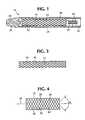
- FIGS. 3 and 4show the prosthesis of FIG. 1 in a radially constrained state, and in a radially expanded state, respectively;
- FIG. 5is an enlarged partial view of FIG. 3, schematically illustrating an interbraiding of structural and textile strands of the prosthesis;
- FIG. 6shows the prosthesis of FIG. 1 deployed within a vessel and spanning an aneurysm
- FIGS. 7 and 8schematically illustrate a process for manufacturing the prosthesis
- FIGS. 9 and 10schematically illustrate an alternative process for manufacturing the prosthesis
- FIGS. 11 a and 11 bare photographs of a prosthesis constructed according to a first exemplary process according to the present invention.
- FIG. 12is a photograph of a prosthesis constructed according to a second exemplary process
- FIG. 13is a photograph of a prosthesis constructed according to a third exemplary process
- FIG. 14is a photograph of a prosthesis constructed according to a fourth exemplary process
- FIG. 15is a diagrammatic view of an alternative embodiment prosthesis
- FIG. 16is an illustration of another alternative embodiment prosthesis
- FIG. 17illustrates a coated multifilament yarn of a further alternative embodiment prosthesis
- FIG. 18illustrates a coated structural strand of another alternative embodiment prosthesis
- FIG. 19illustrates a further alternative embodiment coated prosthesis.
- FIG. 1a deployment device 16 for delivering a prosthesis 18 to an intended fixation location or treatment site within a body lumen, and then controllably releasing the prosthesis for radial self-expansion and fixation within the lumen.
- the deviceincludes an elongate and flexible outer catheter 20 constructed of a biocompatible polymer, e.g. polyurethane.
- a central lumen 22runs the length of catheter 20 .
- a distal portion 24 of the outer cathetersurrounds prosthesis 18 .
- An inner catheter 26is contained within lumen 22 and runs along substantially the entire length of outer catheter 20 .
- At the distal end of inner catheter 26is a tapered distal tip 28 .
- Prosthesis 18surrounds inner catheter 26 , and thus is confined between the inner and outer catheters.
- a lumen 30 in the inner cathetercan accommodate a flexible guidewire.
- Prosthesis 18shown completely rather than in section, is a tubular braided structure including helically wound monofilament structural strands 32 formed of a resilient material.
- prosthesis 18is elastically compressed into a reduced radius axially elongated delivery state.
- Outer catheter 20confines the prosthesis, maintaining it in the delivery state against an elastic restoring force.
- An annular detent 34mounted to inner catheter 26 , occupies a space between the inner and outer catheters to limit proximal travel of prosthesis 18 relative to the inner catheter. Thus, as outer catheter 20 is moved proximally relative to inner catheter 26 , the detent prevents the prosthesis from moving with the outer catheter.
- Catheters 20 and 26while maintaining prosthesis 18 in the delivery configuration, are moved transluminally, e.g. through vasculature, to deliver the prosthesis to the intended treatment site once the prosthesis is positioned as intended, inner catheter 26 is held stationary, while outer catheter 20 is withdrawn proximally.
- Detent 34prevents prosthesis 18 from moving proximally with the outer catheter, thus to maintain the prosthesis properly aligned as it progressively radially self-expands toward a relaxed state and into intimate contact with tissue at the treatment site. Because the prosthesis does not expand completely to the relaxed state, it exerts a residual force on the tissue that tends to maintain fixation of the prosthesis. At this point the prosthesis has a diameter much larger than the diameter of distal tip 28 , so that the inner catheter and tip, along with the outer catheter, are easily proximally withdrawn.
- Prosthesis 18resembles a radially self-expanding stent, in that it is well suited for radially compressed delivery and self-expansion. Accordingly, familiarity with radially self-expanding stents is useful in considering prosthesis 18 .
- FIGS. 2 a and 2 bA radially self-expanding stent is pictured in FIGS. 2 a and 2 b .
- the stentconsists of two oppositely directed and concentric sets of helically wound thread elements or wires.
- the wirescan be formed of metal or a polymeric material and have good elastic recovery.
- Each wireis selectively shaped so that its nominal shape, i.e. its shape when in a relaxed state subject to no external stresses, is helical.
- the wirescooperate to give the stent its nominal tubular shape.
- Adjacent helices in two opposite winding directionsare spaced apart axially, resulting in rhombotic voids or interstices with dimensions substantially larger than the wire diameters.
- the open-mesh constructionin combination with the resiliency and strength of the selectively shaped wires, enables and facilitates (a) elastic compression of the stent to a much smaller radius suitable for intraluminal delivery; (b) virtually instantaneous radial expansion of the stent when released at a treatment site; and (c) a sufficient residual force to ensure acute fixation without hooks or barbs, although such fixation options may enhance fixation.
- structural strands 32form a latticework 35 of prosthesis 18 .
- strands 32are arranged in two oppositely directed and concentric sets of helices, spaced apart axially from one another to define rhombotic interstices.
- Structural strands 32further are similar to the wires in that they exhibit the requisite strength and elasticity, are biocompatible, resistant to fatigue and corrosion, and in vascular applications are hemocompatible as well.
- Materials meeting these needsinclude certain stainless “spring” steels, cobalt-based alloys, and alloys containing titanium.
- cobalt-based alloysare sold under the brand names “Elgiloy”, “Phynox” and “MP35N”.
- CoCrMO alloysare described in U.S. patent application Ser. No. 08/640,253 (now U.S. Pat. No. 5,891,191) entitled “Cobalt-Chromium-Molybdenum Alloy Stent and Stent Graft” (J. Stinson), assigned to the assignee of this application and filed concurrently herewith. These alloys contain less than about 5 weight percent nickel, preferably less than about 2 weight percent nickel and more preferably no more than about 1 weight percent nickel. Chromium is preferably present in an amount between about 26.0 and 30.0 weight percent, and molybdenum preferably in an amount between about 5.0 and 7.0 weight percent.
- the alloysfurther can include nitrogen in an amount up to about 0.25 weight percent, and carbon in an amount up to about 0.35 weight percent.
- Other elementspreferably in amounts no greater than about 1.0 weight percent, include iron, silicon, manganese, copper, phosphorous, sulfur and tungsten.
- the balance of the alloy in each casecan be cobalt, preferably in an amount of at least 60.0 weight percent. Specific examples are described in this application, which is incorporated by reference herein.
- a preferred alloy of titaniumis a recovery metal alloy of nickel and titanium, sold under the brand name “Nitinol”.
- Other titanium alloysare disclosed in U.S. patent application Ser. No. 08/598,751 entitled “Titanium Alloy Self-Expanding Stent”, filed Feb. 8, 1996 and assigned to the assignee of this application.
- Other suitable titanium alloysinclude titanium-zirconium-niobium alloys and a titanium-aluminum-vanadium alloy known as TI-6Al-4V.
- Suitable polymeric monofilamentsinclude PET, polypropylene, PEEK, HDPE, polysulfone, acetyl, PTFE, FEP, polycarbonate urethane and polyurethane.
- Suitable polyurethanes and polycarbonate urethanesinclude those sold under the following brand names: Chronoflex AR, Chronoflex Al, Corethane, and Biomer. These monofilaments preferably have diameters in the range of about 0.002-0.015 inches (0.051-0.38 mm).
- structural strands 32intersect each other to define a braid angle ⁇ , which is bisected by a longitudinal axis 36 of the prosthesis.
- the braid anglewhen prosthesis 18 is in the relaxed state, is in the range of about 60 to 150 degrees, and more preferably 80 to 140 degrees.
- radial compression of the prosthesissubstantially reduces the braid angle.
- the braid anglelargely determines the relationship between radial compression and axial elongation of the prosthesis. More particularly, smaller braid angles yield less axial shortening for a given amount of radial expansion. On the other hand, for a given strand size and strength, a larger braid angle imparts greater resistance to radial compression and more positive acute fixation. Accordingly a smaller braid angle generally requires a structural strand that is resilient, but stronger, i.e. with a higher modulus of elasticity.
- textile sheeting or fabric 40The interstices 38 between adjacent structural strands in prosthesis 18 are occupied by a textile sheeting or fabric 40 .
- sheeting 40is formed of multiple textile strands 42 interbraided with one another and further interbraided with structural strands 32 .
- Strands 32 and 42are illustrated in a one over one braiding pattern.
- Textile strands 42also are provided in sets of oppositely directed helices, and intersect one another at the same braid angle a defined by the structural strands.
- Textile strands 42preferably are multifilament yarns, although they can be monofilaments.
- the textile strandsare much finer than the structural strands, ranging from about 10 to 400 denier.
- Individual filaments of the multifilament yarnscan range from about 0.25 to about 10 denier.
- the multifilament yarnsgenerally have a high degree of compliance, which may or may not include elasticity. Suitable materials include PET, polypropylene, polyurethane, polycarbonate urethane, HDPE, polyethene, silicone, PTFE, ePTFE and polyolefin.
- One suitable high molecular weight polyethyleneis sold under the brand name “Spectra”.
- textile sheeting 40can be microporous, yet essentially impervious to body fluids. Also, the textile sheeting is highly compliant, conforming to changes in the shape of latticework 35 as prosthesis 18 either radially self-expands or is radially compressed. The shape of latticework 35 determines the shape of the prosthesis.
- prosthesis 18combines the favorable attributes of self-expanding stents and grafts.
- Latticework 35provides radial compressibility, self-expansion over a wide range of radii and residual force for acute fixation, while textile sheeting 40 reduces permeability to the extent that the prosthesis is essentially impervious to blood and other body fluids.
- prosthesis 18is particularly well suited to treating an aneurysm.
- FIG. 6illustrates fixation of prosthesis 18 within a blood vessel having a vessel wall 44 . Along the vessel wall is in an aneurysm 46 . Opposite end regions 48 and 50 of the prosthesis have radially expanded into intimate contact with vessel wall 44 on opposite sides of the aneurysm.
- a medial region 52 of the prosthesisspans the aneurysm. End regions 48 and 50 effectively fix the prosthesis, due to the resilience and strength of the structural strand latticework. At the same time the prosthesis, because of textile sheeting 40 , shunts blood past the aneurysm preventing any substantial leakage into the aneurysmal sack.
- a particularly favorable structure for prosthesis 18is an interbraiding of metallic structural strands with Dacron (polyester) multifilament yarns as the textile strands.
- the metal structural strandsexhibit high strength in terms of elastic moduli.
- stainless steelscan have elastic moduli of about 28-30 ⁇ 10 6 psi. Titanium and alloys of titanium tend to have elastic moduli in the range of 15.4-16.6 ⁇ 10 6 psi.
- polyethylenefor example, has an elastic modulus in the range of about 0.02-0.055 ⁇ 10 6 psi, and other polymeric materials have elastic moduli in this order of magnitude.
- a latticework of metallic strandsis considerably more resistant to radial compression, and provides a greater residual force for acute fixation.
- the Dacron polyester multifilament yarnhas a high elastic recovery and elongation (up to 36% for the polyester fiber) and a low elastic modulus, which ensure that textile sheeting 40 conforms to the latticework.
- This favorable composite structurecannot be manufactured by forming a braided structure on a mandrel, then heating the mandrel to thermally set the strands in their helical shapes.
- Thermally setting metallic structural strandsentails heating the strands to temperatures up to about 1000° C. while the strands are maintained in the intended helical shape. Such temperatures are well above the melting points of polyesters and other materials most suitable for the multifilament yarn textile strands.
- Selectively shaping the structural strandsis important in enhancing the predictability and control over prosthesis contractions and expansions, and also reduces any tendency of the prosthesis to unravel.
- FIG. 7shows two structural strands (metal monofilaments) 32 a and 32 b , one from each set of oppositely directed structural strands, wound about a mandrel 54 and supported by respective bobbins 56 and 58 . While just strands 32 a and 32 b are illustrated as a matter of convenience, it is to be appreciated that all of the structural strands are wound about the mandrel and maintained together for shaping. Only structural strands are present, however, as shaping occurs before interbraiding with the textile strands.
- Age-hardeningis accomplished within a furnace 60 in a vacuum or a protective atmosphere. Temperatures are within the range of about 350-1000° C., with the specific temperature depending on the structural material. The filaments overlie one another to form multiple intersections, one of which is indicated at 62 .
- Bobbins, including 56 and 58are set to tension their respective strands during age-hardening. The appropriate duration for age-hardening varies with materials and dimensions, but can range from as brief as 30 seconds, to about 5 hours.
- nominal shaperefers to the shape in a relaxed state, i.e. when under no external stress.
- the age-hardened metallic monofilamentsare highly resilient, i.e. deformable under external stress but elastically returning to the nominal shape when free of the external stress.
- the strands when constructed of a recovery metalare plastically deformable when maintained below an activation temperature, which for Nitinol can be below body temperature (about 37° C.). When heated to the activation temperature or above, the structural strand returns to the selected nominal shape.
- the “nominal shape”is the shape to which the strand returns when at or above the activation temperature.
- structural strands 32are thermoplastic rather than metallic monofilaments
- multiple strandsare thermally set in similar fashion. More particularly, with the thermoplastic monofilaments wound in opposite sets about mandrel 54 , the strands are heated to a heat-forming temperature in the range of about 100 to 400° C., more preferably 150 to 250° C., either within a furnace as previously described or by heating the mandrel.
- the strandsare maintained at or above the heat-forming temperature for a duration generally shorter than that of thermally setting metal strands, i.e. from about 30 seconds to about 2 hours, or more preferably 5 to 15 minutes.
- thermally setting metal strandsi.e. from about 30 seconds to about 2 hours, or more preferably 5 to 15 minutes.
- Only the structural strandsare shaped, and before they are interbraided with the textile strands. This sequence can be advantageous even when the structural strands and textile strands are formed of the same thermoplastic material, as it enables fabrication of a pros
- the thermal setting processalters the structural strands, in the sense of changing their shapes from an original or first nominal shape to a second, selected nominal shape.
- the original nominal shapeis linear, with the selected nominal shape determined by the diameter of the mandrel and the pitch at which the structural strands are wound about the mandrel.
- FIG. 8schematically illustrates a braiding apparatus 64 including an annular carrier assembly 66 including a circular array of bobbins, two of which are indicated at 68 and 70 .
- the apparatusfurther includes a mandrel 72 , centered within the annular assembly and movable longitudinally relative to the assembly as indicated by the arrow.
- braiding apparatus 64is used as follows:
- carrier assembly 66is loaded by winding different strands onto different bobbins.
- the type of strand wound on each bobbindepends on the desired braiding pattern and ratio of structural strands to textile strands. All strands are drawn from their respective bobbins to mandrel 72 , and braiding proceeds by moving mandrel 72 longitudinally, while at the same time the bobbins are moved relative to one another as dictated by the desired pattern of braiding, e.g. a two-dimensional maypole braiding. The result is a simultaneous interbraiding of the structural and textile strands onto the mandrel, as indicated at 74 .
- the mandreldetermines the diameter of the braided structure.
- Mandrel longitudinal speedlargely determines the braid angle. Prosthesis lengths are determined by the duration of braiding, or by cutting the braided structure to predetermined lengths upon its removal from the mandrel.
- the braiding processincludes controlling the structural strands as to orientation during braiding, to ensure that the individual helices cooperate to provide the desired nominal tubular configuration for the resulting latticework. Similar control of the textile strands is not necessary, due to their more compliant nature. Properly oriented structural strands diminish any unraveling tendency and result in more predictable contraction and expansion of the prosthesis. Further, from FIG. 5 it can be appreciated that the textile strands, in filling the interstices between structural strands, tend to maintain the structural strands in the desired configuration of intersecting helices.
- FIG. 9schematically illustrates an alternative braiding apparatus 76 in which the structural strands are selectively shaped by cold-working.
- an annular carrier assembly 78is mounted concentrically on a longitudinally movable mandrel 80 .
- the carrier assemblysupports multiple bobbins in a circular array, with two of the bobbins being shown at 82 and 84 .
- a structural strand 32has been wound on the bobbin 82
- bobbin 84carries a textile strand 42 .
- the structural strandis not thermally shaped before braiding, and thus at first has a linear nominal shape.
- Structural strand 32is plastically deformed by cold working as it travels from bobbin 82 to the mandrel.
- a small diameter shaping pulley 86 and a larger diameter idler pulley 88are disposed along the path traversed by strand 32 .
- Shaping pulley 86exerts a bending stress on the moving structural strand trained about this pulley, particularly on radially outward portions of the strand.
- both pulleysare shown in side elevation, it is to be understood that shaping pulley 88 actually is orthogonal to idler pulley 88 to impart the selected nominal shape.
- Bobbin 82is supported on a carrier that includes a clutch (not shown) adjustable to control the tension applied to the strand, thereby to adjust the amount of bending stress.
- the tensionis controlled so that the bending stress, at least along the radially outward portions of the strand along pulley 86 , exceeds the yield stress of the material.
- the appropriate level of tensionis within the range of about 200-1000 gms, depending on such factors as the material, the monofilament diameter, and the bending radius about pulley 86 .
- the resultis a cold-working plastic deformation, represented as a hatched segment 90 in FIG. 10 . It is to be appreciated that segment 90 is greatly exaggerated and intended for illustration only. The actual plastic flow is less pronounced and continuous, and changes the nominal shape of the structural strand from linear to helical.
- pulley 86would impart a curved nominal shape to the structural strand in any event, and that the helical nominal shape with the desired pitch is obtained through proper orientation of the pulley with respect to the carrier assembly while the desired tension in the strand is maintained.
- CoCrMO alloys described in the aforementioned U.S. patent application Ser. No. 08/640,253 (now U.S. Pat. No. 5,891,191) entitled “Cobalt-Chromium-Molybdenum Alloy Stent and Stent Graft”are particularly well suited for this approach.
- the selective shaping and braiding stepscan occur closely in time and within a continuous process.
- thermal shapingis followed by cooling the strands and winding the strands onto bobbins, and therefore involves processing in a batch mode.
- FIGS. 11-14are photographs of four different braiding structures, formed according to the following examples of the braiding process.
- the metallic monofilamentsare thermally shaped prior to braiding, although they can just as well be plastically formed to achieve the same result.
- the bobbins of a braider carrier assemblyare loaded with seventy-two textile filaments, each being a 100 denier polyester yarn composed of seventy filaments.
- a structural strandis wound for co-braiding with the multifilament yarn, to provide twelve structural strands in each of two opposite winding directions.
- Each structural strandis an Elgiloy wire having a diameter of 0.0043 inches (0.11 mm).
- the strandsare braided in a two over two braiding pattern onto an 8 mm diameter round mandrel, with the braider operated to determine a braid angle of 110°. The braid is formed to an adequate length, then removed from the mandrel.
- the resulting interbraided structureshown in FIGS. 11 a and 11 b , is a tubular composite of the polyester yarn and metal monofilaments.
- the wire latticeworkis formed as two sets of oppositely directed helices, with the wires in a two over two braided pattern.
- carrier bobbinsare loaded with seventy-two polyester yarns of 100 denier and seventy filaments.
- a 0.0043 inch diameter Elgiloy wire, provided at every fourth carrier,is co-braided with the multifilament yarn to provide nine wires in each of two opposite winding directions.
- the strandsare braided in a two over two braiding pattern on an 8 mm diameter round mandrel.
- the result, pictured in FIG. 12is a tubular interbraided structure of polyester yarn and metal monofilaments.
- the wire substructureconsists of two concentric sets of oppositely directed helices, not interbraided but overlying one another.
- the carrier bobbinsare loaded with seventy-two 100 denier polyester yarns formed of seventy filaments.
- a 0.0043 inch diameter Elgiloy wireis loaded at every other carrier around the braider in only one of two opposite winding directions, for a total of eighteen wires co-braided with the multifilament yarn.
- the strandsare braided on an 8 mm diameter round mandrel in a two over two braiding pattern, with the braider set to form a braid angle of 110°.
- the result(FIG. 13) is a hollow tubular interbraided structure of polyester yarn and metal monofilaments.
- the wire substructureconsists of a single layer of eighteen axially spaced helices in one winding direction.
- Carrier bobbinsare loaded with one hundred forty-four polyester yarns of 100 denier and seventy filaments.
- An Elgiloy wire of 0.0055 inches (0.13 mm)is loaded at every sixth carrier around the braider, to provide twelve wires in each of two opposite winding directions for co-braiding with the multifilament yarn.
- the Elgiloy wirePrior to loading, the Elgiloy wire is plastically formed into the desired shape as described in connection with FIGS. 9 and 10.
- the strandsare braided onto a 16 mm diameter round mandrel, with the braider set to provide a braid angle of 110°.
- the result, shown in FIG. 14,is a tubular interbraided structure of polyester yarn and metal monofilaments, including a wire substructure consisting of twenty-four wires braided in a one over one braiding pattern.
- the carrier bobbinsare loaded with ninety-six polyester yarns of 100 denier and seventy filaments.
- a 0.0055 inch diameter Elgiloy wireis loaded at every third carrier around the braider, to provide sixteen wires in each of two opposite winding directions for co-braiding with the multifilament yarn.
- the strandsare braided in a two over two braiding pattern on a 12 mm diameter round mandrel, with the braider set to provide a braid angle of 110°.
- the resultis a tubular interbraided structure of the polyester yarn and metal monofilaments, including a wire substructure of thirty-two wires braided in a two over two pattern.
- the resulting prosthesishas water permeability comparable to that of a vascular graft, and can be constrained to a reduced diameter and allowed to expand like a radially self-expanding stent.
- FIG. 15shows a prosthesis 92 formed of helical structural strands 94 interbraided with multifilament yarns forming a textile sheeting 96 .
- a further strand 98is interbraided with the textile strands.
- Strand 98is formed of a radiopaque material, e.g. tantalum.
- Strand 98improves the fluoroscopic imaging of prosthesis 92 at or near a treatment site, to facilitate recognition of proper placement or a need to move the prosthesis.
- Other approaches to enhancing radiopacityinclude use of composite structural strands (e.g. wires with radiopaque cores), plated monofilaments, radiopaque inks and marker bands.
- FIG. 16illustrates a prosthesis 100 fabricated according to the following example:
- a braiding deviceis provided with eighteen triaxial guide tubes arranged about the carrier assembly.
- the bobbinsare loaded with seventy-two polyester yarns of 100 denier and seventy filaments. Every third carrier around the braider is loaded with a 0.0043 diameter Elgiloy wire, to provide twelve wires in each of two opposite winding directions for co-braiding with the multifilament yarns.
- Eighteen aliphatic polyurethane monofilaments of 0.004 inches (0.1 mm) in diameterare provided, one such monofilament fed into each of the triaxial guide tubes for incorporation into the braided structure as axial runners.
- the strandsare braided about an 8 mm diameter round mandrel in a two over two braiding pattern, with the braiding device set to provide a braid angle of 110°.
- the prosthesisis removed and heated in an oven at 150° C. for approximately ten minutes to melt the polyurethane runners, thereby fusing them to the remaining structure.
- tubular interbraided prosthesis 100incorporating metal monofilaments 102 , a sheeting 104 of the polyester yarns, and axial polyurethane runners 106 .
- the wire substructureis braided in a two over two braiding pattern.
- the prosthesishas a water permeability comparable to that of a vascular graft, and can be constrained radially and allowed to self-expand like a self-expanding stent. Radial recovery is enhanced and the tendency to unravel or fray when cut is reduced, due to the axial runners.
- Another approach to reduce unraveling of the prosthesisis to apply a silicone adhesive to the opposite ends, or to submerge the prosthesis ends into a solution of a polyurethane, a silicone, or a polycarbonate urethane and a solvent having a low percentage of solids. Residual polyurethane, silicone or polycarbonate urethane remains after drying and tends to prevent unraveling.
- FIG. 17illustrates a multifilament yarn 108 with a coating 110 of TFE, or alternatively a copolymer of TFE and silicone.
- Coating 110is applied by plasma polymerization prior to braiding. Coating 110 enhances surface properties of the yarn, for example by reducing friction.
- a prosthesis incorporating a sheeting composed of the coated yarns 108can be deployed with less force. Also, inflammatory responses to the implanted stent may be reduced.
- structural strands 112 in FIG. 18, particularly metal monofilamentsare coated with PTFE, ePTFE, polypropylene, polyethylene, PET, or polyurethane. Coating may occur after selective shaping and before braiding, by over-extrusion, tape wrapping, serving or by an additional braiding step. This reduces exposure of the blood flow to metal.
- the processalso can be augmented with a surface coating step after braiding, to provide a prosthesis 114 with a surface coating 116 as illustrated in FIG. 19.
- a portion of the coatingis removed to illustrate a covered portion of the prosthesis.
- At least one end of prosthesis 114can be left uncovered as indicated at 118 , to enhance acute fixation at the exposed end.
- the prosthesiscan be coated over its entire length.
- a surface coating of heparin or coumadinreduces thrombogenicity.
- a surface coating of steroids, e.g. dexamethasonereduces the restenosis rate.
- coatings of albumin, collagen or gelatincan be incorporated to provide an acute reduction in permeability of the textile sheeting.
- prosthesiscan be provided with flared ends, or may be braided with end portions that do not incorporate the multifilament yarns.
- Collagen, PGA and other biological or bioabsorbable materialscan be substituted for portions of the monofilament or multifilament strands.
- Metallocene catalized polymerse.g. polyolefins or polypropylene, and fluorination if desired, may also be incorporated.
- a prosthesisincorporates structural strands interbraided with more tightly woven textile strands that reduce permeability.
- the structural strandsare selectively shaped before their interbraiding with the textile strands, either by a thermal set or by selective plastic deformation, and in either event are shaped without adversely affecting the textile strands.
- Plastic deformation of structural strands by cold-workingis advantageous in permitting a continuous process of cold-working followed by interbraiding.
- the resultis an interbraided prosthesis incorporating the strength, resilience and range of radii associated with self-expanding stents, and the impermeability associated with vascular grafts, in which a selective shaping of the structural strands does not limit the range of materials useable as additional strands in the interbraided structure to reduce permeability, alter porosity, reduce friction or enhance fluoroscopic imaging.
Landscapes
- Health & Medical Sciences (AREA)
- Engineering & Computer Science (AREA)
- Biomedical Technology (AREA)
- Heart & Thoracic Surgery (AREA)
- Life Sciences & Earth Sciences (AREA)
- Cardiology (AREA)
- Oral & Maxillofacial Surgery (AREA)
- Transplantation (AREA)
- Veterinary Medicine (AREA)
- Vascular Medicine (AREA)
- Public Health (AREA)
- Animal Behavior & Ethology (AREA)
- General Health & Medical Sciences (AREA)
- Textile Engineering (AREA)
- Manufacturing & Machinery (AREA)
- Gastroenterology & Hepatology (AREA)
- Pulmonology (AREA)
- Prostheses (AREA)
Abstract
Description
Claims (22)
Priority Applications (2)
| Application Number | Priority Date | Filing Date | Title |
|---|---|---|---|
| US09/496,088US6689162B1 (en) | 1995-10-11 | 2000-02-01 | Braided composite prosthesis |
| US10/775,961US7211109B2 (en) | 1995-10-11 | 2004-02-10 | Braided composite prosthesis |
Applications Claiming Priority (4)
| Application Number | Priority Date | Filing Date | Title |
|---|---|---|---|
| US520995P | 1995-10-11 | 1995-10-11 | |
| US08/640,062US5758562A (en) | 1995-10-11 | 1996-04-30 | Process for manufacturing braided composite prosthesis |
| US08/919,428US6019786A (en) | 1995-10-11 | 1997-08-27 | Braided composite prosthesis |
| US09/496,088US6689162B1 (en) | 1995-10-11 | 2000-02-01 | Braided composite prosthesis |
Related Parent Applications (1)
| Application Number | Title | Priority Date | Filing Date |
|---|---|---|---|
| US08/919,428DivisionUS6019786A (en) | 1995-10-11 | 1997-08-27 | Braided composite prosthesis |
Related Child Applications (1)
| Application Number | Title | Priority Date | Filing Date |
|---|---|---|---|
| US10/775,961DivisionUS7211109B2 (en) | 1995-10-11 | 2004-02-10 | Braided composite prosthesis |
Publications (1)
| Publication Number | Publication Date |
|---|---|
| US6689162B1true US6689162B1 (en) | 2004-02-10 |
Family
ID=30773367
Family Applications (2)
| Application Number | Title | Priority Date | Filing Date |
|---|---|---|---|
| US09/496,088Expired - Fee RelatedUS6689162B1 (en) | 1995-10-11 | 2000-02-01 | Braided composite prosthesis |
| US10/775,961Expired - Fee RelatedUS7211109B2 (en) | 1995-10-11 | 2004-02-10 | Braided composite prosthesis |
Family Applications After (1)
| Application Number | Title | Priority Date | Filing Date |
|---|---|---|---|
| US10/775,961Expired - Fee RelatedUS7211109B2 (en) | 1995-10-11 | 2004-02-10 | Braided composite prosthesis |
Country Status (1)
| Country | Link |
|---|---|
| US (2) | US6689162B1 (en) |
Cited By (61)
| Publication number | Priority date | Publication date | Assignee | Title |
|---|---|---|---|---|
| US20040122511A1 (en)* | 2002-11-05 | 2004-06-24 | Mangiardi Eric K. | Coated stent with geometry determinated functionality and method of making the same |
| US20040162606A1 (en)* | 1995-10-11 | 2004-08-19 | Thompson Paul J. | Braided composite prosthesis |
| US20050261781A1 (en)* | 2004-04-15 | 2005-11-24 | Sennett Andrew R | Cement-directing orthopedic implants |
| WO2005115118A2 (en) | 2004-05-25 | 2005-12-08 | Chestnut Medical Technologies, Inc. | Flexible vascular occluding device |
| US20050288775A1 (en)* | 2004-06-24 | 2005-12-29 | Scimed Life Systems, Inc. | Metallic fibers reinforced textile prosthesis |
| US20060085065A1 (en)* | 2004-10-15 | 2006-04-20 | Krause Arthur A | Stent with auxiliary treatment structure |
| US20060089672A1 (en)* | 2004-10-25 | 2006-04-27 | Jonathan Martinek | Yarns containing filaments made from shape memory alloys |
| US20060258972A1 (en)* | 2005-05-13 | 2006-11-16 | Alveolus, Inc. | Delivery device with viewing window and associated method |
| US20060271153A1 (en)* | 2005-05-25 | 2006-11-30 | Chestnut Medical Technologies, Inc. | System and method for delivering and deploying an occluding device within a vessel |
| US20060271149A1 (en)* | 2005-05-25 | 2006-11-30 | Chestnut Medical Technologies, Inc. | System and method for delivering and deploying an occluding device within a vessel |
| US7252680B2 (en) | 2001-04-18 | 2007-08-07 | Alveolus, Inc. | Removable essentially cylindrical implants |
| US20070260268A1 (en)* | 2005-02-14 | 2007-11-08 | Bartee Chad M | PTFE composite multi-layer material |
| US20080082154A1 (en)* | 2006-09-28 | 2008-04-03 | Cook Incorporated | Stent Graft Delivery System for Accurate Deployment |
| US20080119943A1 (en)* | 2006-11-16 | 2008-05-22 | Armstrong Joseph R | Stent having flexibly connected adjacent stent elements |
| US20080132998A1 (en)* | 2004-09-29 | 2008-06-05 | Alveolus, Inc. | Active stent |
| US20080208320A1 (en)* | 2006-12-15 | 2008-08-28 | Francisca Tan-Malecki | Delivery Apparatus and Methods for Vertebrostenting |
| US7527644B2 (en) | 2002-11-05 | 2009-05-05 | Alveolus Inc. | Stent with geometry determinated functionality and method of making the same |
| US7547321B2 (en) | 2001-07-26 | 2009-06-16 | Alveolus Inc. | Removable stent and method of using the same |
| US20090182413A1 (en)* | 2008-01-11 | 2009-07-16 | Burkart Dustin C | Stent having adjacent elements connected by flexible webs |
| US20090287288A1 (en)* | 2004-05-25 | 2009-11-19 | Chestnut Medical Technologies, Inc. | Methods and apparatus for luminal stenting |
| US20090287292A1 (en)* | 2008-05-13 | 2009-11-19 | Becking Frank P | Braid Implant Delivery Systems |
| US20090318947A1 (en)* | 2005-05-25 | 2009-12-24 | Chestnut Medical Technologies, Inc. | System and method for delivering and deploying an occluding device within a vessel |
| US20090326538A1 (en)* | 2006-12-15 | 2009-12-31 | Sennett Andrew R | Devices and methods for fracture reduction |
| US20100268319A1 (en)* | 2009-04-17 | 2010-10-21 | Medtronic Vascular, Inc. | Mobile External Coupling for Branch Vessel Connection |
| US20100268327A1 (en)* | 2009-04-17 | 2010-10-21 | Medtronic Vascular, Inc. | Mobile External Coupling for Branch Vessel Connection |
| US7833263B2 (en) | 2005-04-01 | 2010-11-16 | Boston Scientific Scimed, Inc. | Hybrid vascular graft reinforcement |
| US7875068B2 (en) | 2002-11-05 | 2011-01-25 | Merit Medical Systems, Inc. | Removable biliary stent |
| US7959671B2 (en) | 2002-11-05 | 2011-06-14 | Merit Medical Systems, Inc. | Differential covering and coating methods |
| US20110166592A1 (en)* | 2004-05-25 | 2011-07-07 | Chestnut Medical Technologies, Inc. | Flexible vascular occluding device |
| US20110238094A1 (en)* | 2010-03-25 | 2011-09-29 | Thomas Jonathan D | Hernia Patch |
| US8088060B2 (en) | 2000-03-15 | 2012-01-03 | Orbusneich Medical, Inc. | Progenitor endothelial cell capturing with a drug eluting implantable medical device |
| AU2011213729B2 (en)* | 2004-05-25 | 2013-01-10 | Covidien Lp | Flexible vascular occluding device |
| US8394119B2 (en) | 2006-02-22 | 2013-03-12 | Covidien Lp | Stents having radiopaque mesh |
| US8414635B2 (en) | 1999-02-01 | 2013-04-09 | Idev Technologies, Inc. | Plain woven stents |
| US8419788B2 (en) | 2006-10-22 | 2013-04-16 | Idev Technologies, Inc. | Secured strand end devices |
| CN103153505A (en)* | 2010-07-12 | 2013-06-12 | 斯奈克玛 | Method for producing a solid part |
| WO2013167493A1 (en)* | 2012-05-07 | 2013-11-14 | Jotec Gmbh | In-situ fenestrated intraluminal vascular prosthesis |
| US8617234B2 (en) | 2004-05-25 | 2013-12-31 | Covidien Lp | Flexible vascular occluding device |
| US20140121744A1 (en)* | 2012-10-31 | 2014-05-01 | Covidien Lp | Methods and systems for increasing a density of a region of a vascular device |
| US8876881B2 (en) | 2006-10-22 | 2014-11-04 | Idev Technologies, Inc. | Devices for stent advancement |
| US9023095B2 (en) | 2010-05-27 | 2015-05-05 | Idev Technologies, Inc. | Stent delivery system with pusher assembly |
| US20150133994A1 (en)* | 2004-03-19 | 2015-05-14 | Aga Medical Corporation | Multi-layer braided structures for occluding vascular defects |
| US20150164633A1 (en)* | 2009-12-31 | 2015-06-18 | W. L. Gore & Associates, Inc. | Method of making an endoprosthesis containing multi-phase stainless steel |
| US9114001B2 (en) | 2012-10-30 | 2015-08-25 | Covidien Lp | Systems for attaining a predetermined porosity of a vascular device |
| US9157174B2 (en) | 2013-02-05 | 2015-10-13 | Covidien Lp | Vascular device for aneurysm treatment and providing blood flow into a perforator vessel |
| US9155647B2 (en) | 2012-07-18 | 2015-10-13 | Covidien Lp | Methods and apparatus for luminal stenting |
| US9173736B2 (en) | 2011-04-28 | 2015-11-03 | Medtronic Vascular, Inc. | Method of making an endoluminal vascular prosthesis |
| US9480485B2 (en) | 2006-12-15 | 2016-11-01 | Globus Medical, Inc. | Devices and methods for vertebrostenting |
| US9522217B2 (en) | 2000-03-15 | 2016-12-20 | Orbusneich Medical, Inc. | Medical device with coating for capturing genetically-altered cells and methods for using same |
| US9943427B2 (en) | 2012-11-06 | 2018-04-17 | Covidien Lp | Shaped occluding devices and methods of using the same |
| US10004618B2 (en) | 2004-05-25 | 2018-06-26 | Covidien Lp | Methods and apparatus for luminal stenting |
| IT201700024716A1 (en)* | 2017-03-06 | 2018-09-06 | Cardiovascular Lab S P A O Brevemente Cv Lab S P A | METHOD OF MANUFACTURE OF A LUMINAL ENDOPROSTHESIS |
| US10299948B2 (en) | 2014-11-26 | 2019-05-28 | W. L. Gore & Associates, Inc. | Balloon expandable endoprosthesis |
| EP2816981B1 (en)* | 2012-02-23 | 2019-08-07 | Medtronic Vascular Inc. | Method of forming a nitinol stent |
| US10568752B2 (en) | 2016-05-25 | 2020-02-25 | W. L. Gore & Associates, Inc. | Controlled endoprosthesis balloon expansion |
| US11008676B2 (en) | 2015-12-16 | 2021-05-18 | Edwards Lifesciences Corporation | Textured woven fabric for use in implantable bioprostheses |
| US11224910B2 (en)* | 2017-03-03 | 2022-01-18 | Cook Medical Technologies Llc | Method of forming a bend of a predetermined bend angle in a shape memory alloy wire and method of making a self-expanding stent |
| US11324613B2 (en) | 2017-03-06 | 2022-05-10 | Cardiovascular Lab S.P.A. O Brevemente Cv Lab S.P.A. | Multilayer luminal endoprosthesis and manufacturing method |
| US11759317B2 (en) | 2016-12-20 | 2023-09-19 | Edwards Lifesciences Corporation | Three-dimensional woven fabric implant devices |
| US12064348B2 (en) | 2020-04-03 | 2024-08-20 | Edwards Lifesciences Corporation | Multi-layer covering for a prosthetic heart valve |
| US12390554B2 (en) | 2018-05-21 | 2025-08-19 | Greatbatch Ltd. | Method for making insertable medical devices with low profile composite coverings |
Families Citing this family (78)
| Publication number | Priority date | Publication date | Assignee | Title |
|---|---|---|---|---|
| EP0891752B1 (en)* | 1997-07-17 | 2005-01-12 | Schneider (Europe) GmbH | Stent and method for manufacturing such a stent |
| EP1838242A2 (en)* | 2005-01-21 | 2007-10-03 | Gen 4, LLC | Modular stent graft employing bifurcated graft and leg locking stent elements |
| US8778008B2 (en)* | 2006-01-13 | 2014-07-15 | Aga Medical Corporation | Intravascular deliverable stent for reinforcement of vascular abnormalities |
| US8900287B2 (en)* | 2006-01-13 | 2014-12-02 | Aga Medical Corporation | Intravascular deliverable stent for reinforcement of abdominal aortic aneurysm |
| US20070203564A1 (en)* | 2006-02-28 | 2007-08-30 | Boston Scientific Scimed, Inc. | Biodegradable implants having accelerated biodegradation properties in vivo |
| AU2012200180B2 (en)* | 2006-05-24 | 2013-10-10 | Covidien Lp | Flexible vascular occluding device |
| US9034007B2 (en) | 2007-09-21 | 2015-05-19 | Insera Therapeutics, Inc. | Distal embolic protection devices with a variable thickness microguidewire and methods for their use |
| US8303650B2 (en) | 2008-01-10 | 2012-11-06 | Telesis Research, Llc | Biodegradable self-expanding drug-eluting prosthesis |
| US8317857B2 (en)* | 2008-01-10 | 2012-11-27 | Telesis Research, Llc | Biodegradable self-expanding prosthesis |
| EP2259749A1 (en)* | 2008-03-13 | 2010-12-15 | Tavor (I.T.N) Ltd. | Ligament and tendon prosthesis |
| EP2633823B1 (en) | 2008-04-21 | 2016-06-01 | Covidien LP | Braid-ball embolic devices and delivery systems |
| US10028747B2 (en) | 2008-05-01 | 2018-07-24 | Aneuclose Llc | Coils with a series of proximally-and-distally-connected loops for occluding a cerebral aneurysm |
| US10716573B2 (en) | 2008-05-01 | 2020-07-21 | Aneuclose | Janjua aneurysm net with a resilient neck-bridging portion for occluding a cerebral aneurysm |
| US8974487B2 (en)* | 2008-05-01 | 2015-03-10 | Aneuclose Llc | Aneurysm occlusion device |
| KR101547200B1 (en)* | 2008-06-27 | 2015-09-04 | 가부시키가이샤 교토 이료 세케이 | Vascular stent |
| US9179918B2 (en) | 2008-07-22 | 2015-11-10 | Covidien Lp | Vascular remodeling device |
| US20100131002A1 (en)* | 2008-11-24 | 2010-05-27 | Connor Robert A | Stent with a net layer to embolize and aneurysm |
| CA2743803C (en)* | 2008-11-24 | 2016-12-13 | The Medical Research, Infrastructure, And Health Services Fund Of The Tel Aviv Medical Center | External stent |
| WO2010139340A1 (en)* | 2009-05-30 | 2010-12-09 | Deutsche Institute für Textil- und Faserforschung Denkendorf Stiftung des öffentlichen Rechts | Medical device |
| CA3009244C (en) | 2009-06-23 | 2020-04-28 | Endospan Ltd. | Vascular prostheses for treating aneurysms |
| WO2011004374A1 (en) | 2009-07-09 | 2011-01-13 | Endospan Ltd. | Apparatus for closure of a lumen and methods of using the same |
| US9095342B2 (en) | 2009-11-09 | 2015-08-04 | Covidien Lp | Braid ball embolic device features |
| US9358140B1 (en) | 2009-11-18 | 2016-06-07 | Aneuclose Llc | Stent with outer member to embolize an aneurysm |
| US8906057B2 (en)* | 2010-01-04 | 2014-12-09 | Aneuclose Llc | Aneurysm embolization by rotational accumulation of mass |
| WO2011094634A1 (en) | 2010-01-28 | 2011-08-04 | Micro Therapeutics, Inc. | Vascular remodeling device |
| WO2011094638A1 (en) | 2010-01-28 | 2011-08-04 | Micro Therapeutics, Inc. | Vascular remodeling device |
| US9468517B2 (en) | 2010-02-08 | 2016-10-18 | Endospan Ltd. | Thermal energy application for prevention and management of endoleaks in stent-grafts |
| US20110208289A1 (en)* | 2010-02-25 | 2011-08-25 | Endospan Ltd. | Flexible Stent-Grafts |
| US8353952B2 (en)* | 2010-04-07 | 2013-01-15 | Medtronic Vascular, Inc. | Stent with therapeutic substance |
| US8425548B2 (en) | 2010-07-01 | 2013-04-23 | Aneaclose LLC | Occluding member expansion and then stent expansion for aneurysm treatment |
| FR2962482B1 (en)* | 2010-07-12 | 2012-07-13 | Snecma | METHOD OF MAKING A MASSIVE PIECE |
| EP2603169A1 (en)* | 2010-08-09 | 2013-06-19 | Tavor (I.T.N) Ltd. | Ligament and tendon prosthesis made from cables of filaments |
| WO2012037327A1 (en) | 2010-09-16 | 2012-03-22 | Mayo Foundation For Medical Education And Research | Mechanically adjustable variable diameter stent |
| US9839540B2 (en) | 2011-01-14 | 2017-12-12 | W. L. Gore & Associates, Inc. | Stent |
| US10166128B2 (en) | 2011-01-14 | 2019-01-01 | W. L. Gore & Associates. Inc. | Lattice |
| CA2826022A1 (en) | 2011-02-03 | 2012-08-09 | Endospan Ltd. | Implantable medical devices constructed of shape memory material |
| JP5868432B2 (en) | 2011-02-11 | 2016-02-24 | コヴィディエン リミテッド パートナーシップ | Two-stage deployed aneurysm embolization device |
| US20120245674A1 (en) | 2011-03-25 | 2012-09-27 | Tyco Healthcare Group Lp | Vascular remodeling device |
| US10052218B2 (en) | 2011-04-18 | 2018-08-21 | Vascular Graft Solutions Ltd. | Devices and methods for deploying implantable sleeves over blood vessels |
| US9138232B2 (en) | 2011-05-24 | 2015-09-22 | Aneuclose Llc | Aneurysm occlusion by rotational dispensation of mass |
| US20120330341A1 (en) | 2011-06-22 | 2012-12-27 | Becking Frank P | Folded-Flat Aneurysm Embolization Devices |
| US9254209B2 (en) | 2011-07-07 | 2016-02-09 | Endospan Ltd. | Stent fixation with reduced plastic deformation |
| US8715334B2 (en) | 2011-07-14 | 2014-05-06 | Boston Scientific Scimed, Inc. | Anti-migration stent with quill filaments |
| US9980833B2 (en)* | 2011-08-04 | 2018-05-29 | Cook Medical Technologies Llc | Uniform expandable and collapsible stent |
| US9839510B2 (en) | 2011-08-28 | 2017-12-12 | Endospan Ltd. | Stent-grafts with post-deployment variable radial displacement |
| US9060886B2 (en) | 2011-09-29 | 2015-06-23 | Covidien Lp | Vascular remodeling device |
| US9427339B2 (en) | 2011-10-30 | 2016-08-30 | Endospan Ltd. | Triple-collar stent-graft |
| US9597204B2 (en) | 2011-12-04 | 2017-03-21 | Endospan Ltd. | Branched stent-graft system |
| JP6220386B2 (en) | 2012-05-14 | 2017-10-25 | シー・アール・バード・インコーポレーテッドC R Bard Incorporated | Uniformly expandable stent |
| WO2013171730A1 (en) | 2012-05-15 | 2013-11-21 | Endospan Ltd. | Stent-graft with fixation elements that are radially confined for delivery |
| WO2014020609A1 (en)* | 2012-08-01 | 2014-02-06 | Endospan Ltd. | Stent-grafts configured for post-implantation expansion |
| US9314248B2 (en) | 2012-11-06 | 2016-04-19 | Covidien Lp | Multi-pivot thrombectomy device |
| US9931193B2 (en) | 2012-11-13 | 2018-04-03 | W. L. Gore & Associates, Inc. | Elastic stent graft |
| US9295571B2 (en) | 2013-01-17 | 2016-03-29 | Covidien Lp | Methods and apparatus for luminal stenting |
| DE102013201707A1 (en)* | 2013-02-01 | 2014-08-07 | Aesculap Ag | Vascular prosthesis e.g. aorta sine prosthesis, for use as vessel patch i.e. two-dimensional sheet, of patient for e.g. replacement of defective wall, has orientation unit extending along direction of prosthesis and comprising interruptions |
| USD723165S1 (en) | 2013-03-12 | 2015-02-24 | C. R. Bard, Inc. | Stent |
| US20160030169A1 (en)* | 2013-03-13 | 2016-02-04 | Aortic Innovations, Llc | Dual frame stent and valve devices and implantation |
| US9463105B2 (en) | 2013-03-14 | 2016-10-11 | Covidien Lp | Methods and apparatus for luminal stenting |
| US10736758B2 (en) | 2013-03-15 | 2020-08-11 | Covidien | Occlusive device |
| US8715314B1 (en) | 2013-03-15 | 2014-05-06 | Insera Therapeutics, Inc. | Vascular treatment measurement methods |
| US8690907B1 (en) | 2013-03-15 | 2014-04-08 | Insera Therapeutics, Inc. | Vascular treatment methods |
| CN105228688B (en) | 2013-03-15 | 2019-02-19 | 伊瑟拉医疗公司 | Vascular treatment devices and methods |
| US8679150B1 (en) | 2013-03-15 | 2014-03-25 | Insera Therapeutics, Inc. | Shape-set textile structure based mechanical thrombectomy methods |
| US9907684B2 (en) | 2013-05-08 | 2018-03-06 | Aneuclose Llc | Method of radially-asymmetric stent expansion |
| US9968435B2 (en)* | 2013-07-10 | 2018-05-15 | Terumo Kabushiki Kaisha | Body lumen graft base, production method of body lumen graft base, and body lumen graft using the same |
| WO2015075708A1 (en) | 2013-11-19 | 2015-05-28 | Endospan Ltd. | Stent system with radial-expansion locking |
| US20150148888A1 (en)* | 2013-11-26 | 2015-05-28 | Cook Medical Technologies Llc | Braided stent |
| US10842918B2 (en) | 2013-12-05 | 2020-11-24 | W.L. Gore & Associates, Inc. | Length extensible implantable device and methods for making such devices |
| CN106029005B (en) | 2014-12-18 | 2018-01-19 | 恩都思潘有限公司 | The Endovascular stent-graft of horizontal conduit with tired resistance |
| CN107427377B (en)* | 2015-01-12 | 2019-09-03 | 微仙美国有限公司 | bracket |
| US10478194B2 (en) | 2015-09-23 | 2019-11-19 | Covidien Lp | Occlusive devices |
| CN108697423A (en) | 2016-02-16 | 2018-10-23 | 伊瑟拉医疗公司 | The part flow arrangement of suction unit and anchoring |
| EP4233806A3 (en) | 2016-04-21 | 2023-09-06 | W. L. Gore & Associates, Inc. | Diametrically adjustable endoprostheses |
| JP7217701B2 (en)* | 2016-10-27 | 2023-02-03 | ラピッド メディカル リミテッド | Woven wire intraluminal device |
| CN111194190A (en)* | 2017-10-09 | 2020-05-22 | W.L.戈尔及同仁股份有限公司 | Matched support covering piece |
| US11065136B2 (en) | 2018-02-08 | 2021-07-20 | Covidien Lp | Vascular expandable devices |
| US11065009B2 (en) | 2018-02-08 | 2021-07-20 | Covidien Lp | Vascular expandable devices |
| CN118267008A (en)* | 2022-12-29 | 2024-07-02 | 先健科技(深圳)有限公司 | Plugging device |
Citations (13)
| Publication number | Priority date | Publication date | Assignee | Title |
|---|---|---|---|---|
| US4655771A (en)* | 1982-04-30 | 1987-04-07 | Shepherd Patents S.A. | Prosthesis comprising an expansible or contractile tubular body |
| US4834755A (en)* | 1983-04-04 | 1989-05-30 | Pfizer Hospital Products Group, Inc. | Triaxially-braided fabric prosthesis |
| US5197978A (en)* | 1991-04-26 | 1993-03-30 | Advanced Coronary Technology, Inc. | Removable heat-recoverable tissue supporting device |
| US5423849A (en)* | 1993-01-15 | 1995-06-13 | Target Therapeutics, Inc. | Vasoocclusion device containing radiopaque fibers |
| US5476507A (en)* | 1991-02-27 | 1995-12-19 | Terumo Kabushiki Kaisha | Vascular prostheses |
| US5562725A (en)* | 1992-09-14 | 1996-10-08 | Meadox Medicals Inc. | Radially self-expanding implantable intraluminal device |
| US5697969A (en)* | 1991-03-25 | 1997-12-16 | Meadox Medicals, Inc. | Vascular prosthesis and method of implanting |
| US5891193A (en)* | 1993-11-04 | 1999-04-06 | C.R. Bard, Inc. | Non-migrating vascular prosthesis and minimally invasive placement system therefor |
| US6019786A (en)* | 1995-10-11 | 2000-02-01 | Schneider (Usa) Inc | Braided composite prosthesis |
| US20010000188A1 (en)* | 1996-01-05 | 2001-04-05 | Lenker Jay A. | Limited expansion endoluminal prostheses and methods for their use |
| US6221099B1 (en)* | 1992-05-20 | 2001-04-24 | Boston Scientific Corporation | Tubular medical prosthesis |
| US20010056299A1 (en)* | 1996-04-30 | 2001-12-27 | Thompson Paul J. | Three-dimensional braided covered stent |
| US6342068B1 (en)* | 1996-04-30 | 2002-01-29 | Schneider (Usa) Inc | Three-dimensional braided stent |
Family Cites Families (6)
| Publication number | Priority date | Publication date | Assignee | Title |
|---|---|---|---|---|
| SE9102448D0 (en)* | 1990-08-28 | 1991-08-26 | Meadox Medicals Inc | RAVEL RESISTANT, SELF-SUPPORTING WOVEN GRAFT |
| US5282867A (en)* | 1992-05-29 | 1994-02-01 | Mikhail Michael W E | Prosthetic knee joint |
| CA2158757C (en)* | 1993-04-23 | 2000-01-04 | Joseph E. Laptewicz Jr. | Covered stent and stent delivery device |
| DE69507800T2 (en)* | 1994-05-19 | 1999-07-22 | Scimed Life Systems, Inc., Maple Grove, Minn. | IMPROVED TISSUE SUPPORTS |
| ES2340142T3 (en)* | 1994-07-08 | 2010-05-31 | Ev3 Inc. | SYSTEM TO CARRY OUT AN INTRAVASCULAR PROCEDURE. |
| US6689162B1 (en)* | 1995-10-11 | 2004-02-10 | Boston Scientific Scimed, Inc. | Braided composite prosthesis |
- 2000
- 2000-02-01USUS09/496,088patent/US6689162B1/ennot_activeExpired - Fee Related
- 2004
- 2004-02-10USUS10/775,961patent/US7211109B2/ennot_activeExpired - Fee Related
Patent Citations (15)
| Publication number | Priority date | Publication date | Assignee | Title |
|---|---|---|---|---|
| US4655771A (en)* | 1982-04-30 | 1987-04-07 | Shepherd Patents S.A. | Prosthesis comprising an expansible or contractile tubular body |
| US4655771B1 (en)* | 1982-04-30 | 1996-09-10 | Medinvent Ams Sa | Prosthesis comprising an expansible or contractile tubular body |
| US4834755A (en)* | 1983-04-04 | 1989-05-30 | Pfizer Hospital Products Group, Inc. | Triaxially-braided fabric prosthesis |
| US5476507A (en)* | 1991-02-27 | 1995-12-19 | Terumo Kabushiki Kaisha | Vascular prostheses |
| US5697969A (en)* | 1991-03-25 | 1997-12-16 | Meadox Medicals, Inc. | Vascular prosthesis and method of implanting |
| US5197978A (en)* | 1991-04-26 | 1993-03-30 | Advanced Coronary Technology, Inc. | Removable heat-recoverable tissue supporting device |
| US5197978B1 (en)* | 1991-04-26 | 1996-05-28 | Advanced Coronary Tech | Removable heat-recoverable tissue supporting device |
| US6221099B1 (en)* | 1992-05-20 | 2001-04-24 | Boston Scientific Corporation | Tubular medical prosthesis |
| US5562725A (en)* | 1992-09-14 | 1996-10-08 | Meadox Medicals Inc. | Radially self-expanding implantable intraluminal device |
| US5423849A (en)* | 1993-01-15 | 1995-06-13 | Target Therapeutics, Inc. | Vasoocclusion device containing radiopaque fibers |
| US5891193A (en)* | 1993-11-04 | 1999-04-06 | C.R. Bard, Inc. | Non-migrating vascular prosthesis and minimally invasive placement system therefor |
| US6019786A (en)* | 1995-10-11 | 2000-02-01 | Schneider (Usa) Inc | Braided composite prosthesis |
| US20010000188A1 (en)* | 1996-01-05 | 2001-04-05 | Lenker Jay A. | Limited expansion endoluminal prostheses and methods for their use |
| US20010056299A1 (en)* | 1996-04-30 | 2001-12-27 | Thompson Paul J. | Three-dimensional braided covered stent |
| US6342068B1 (en)* | 1996-04-30 | 2002-01-29 | Schneider (Usa) Inc | Three-dimensional braided stent |
Cited By (158)
| Publication number | Priority date | Publication date | Assignee | Title |
|---|---|---|---|---|
| US7211109B2 (en)* | 1995-10-11 | 2007-05-01 | Schneider (Usa) Inc. | Braided composite prosthesis |
| US20040162606A1 (en)* | 1995-10-11 | 2004-08-19 | Thompson Paul J. | Braided composite prosthesis |
| US8974516B2 (en) | 1999-02-01 | 2015-03-10 | Board Of Regents, The University Of Texas System | Plain woven stents |
| US9925074B2 (en) | 1999-02-01 | 2018-03-27 | Board Of Regents, The University Of Texas System | Plain woven stents |
| US8876880B2 (en) | 1999-02-01 | 2014-11-04 | Board Of Regents, The University Of Texas System | Plain woven stents |
| US8414635B2 (en) | 1999-02-01 | 2013-04-09 | Idev Technologies, Inc. | Plain woven stents |
| US9522217B2 (en) | 2000-03-15 | 2016-12-20 | Orbusneich Medical, Inc. | Medical device with coating for capturing genetically-altered cells and methods for using same |
| US8088060B2 (en) | 2000-03-15 | 2012-01-03 | Orbusneich Medical, Inc. | Progenitor endothelial cell capturing with a drug eluting implantable medical device |
| US7252680B2 (en) | 2001-04-18 | 2007-08-07 | Alveolus, Inc. | Removable essentially cylindrical implants |
| US7547321B2 (en) | 2001-07-26 | 2009-06-16 | Alveolus Inc. | Removable stent and method of using the same |
| US7875068B2 (en) | 2002-11-05 | 2011-01-25 | Merit Medical Systems, Inc. | Removable biliary stent |
| US8206436B2 (en) | 2002-11-05 | 2012-06-26 | Merit Medical Systems, Inc. | Coated stent with geometry determinated functionality and method of making the same |
| US7959671B2 (en) | 2002-11-05 | 2011-06-14 | Merit Medical Systems, Inc. | Differential covering and coating methods |
| US20040122511A1 (en)* | 2002-11-05 | 2004-06-24 | Mangiardi Eric K. | Coated stent with geometry determinated functionality and method of making the same |
| US20100173066A1 (en)* | 2002-11-05 | 2010-07-08 | Merit Medical Systems, Inc. | Coated stent with geometry determinated functionality and method of making the same |
| US7637942B2 (en) | 2002-11-05 | 2009-12-29 | Merit Medical Systems, Inc. | Coated stent with geometry determinated functionality and method of making the same |
| US7527644B2 (en) | 2002-11-05 | 2009-05-05 | Alveolus Inc. | Stent with geometry determinated functionality and method of making the same |
| US20150133994A1 (en)* | 2004-03-19 | 2015-05-14 | Aga Medical Corporation | Multi-layer braided structures for occluding vascular defects |
| US8100973B2 (en) | 2004-04-15 | 2012-01-24 | Soteira, Inc. | Cement-directing orthopedic implants |
| US7465318B2 (en) | 2004-04-15 | 2008-12-16 | Soteira, Inc. | Cement-directing orthopedic implants |
| US20050261781A1 (en)* | 2004-04-15 | 2005-11-24 | Sennett Andrew R | Cement-directing orthopedic implants |
| US8398701B2 (en) | 2004-05-25 | 2013-03-19 | Covidien Lp | Flexible vascular occluding device |
| US9801744B2 (en) | 2004-05-25 | 2017-10-31 | Covidien Lp | Methods and apparatus for luminal stenting |
| US11771433B2 (en) | 2004-05-25 | 2023-10-03 | Covidien Lp | Flexible vascular occluding device |
| US10918389B2 (en) | 2004-05-25 | 2021-02-16 | Covidien Lp | Flexible vascular occluding device |
| US20090287288A1 (en)* | 2004-05-25 | 2009-11-19 | Chestnut Medical Technologies, Inc. | Methods and apparatus for luminal stenting |
| US20090287241A1 (en)* | 2004-05-25 | 2009-11-19 | Chestnut Medical Technologies, Inc. | Methods and apparatus for luminal stenting |
| US10765542B2 (en) | 2004-05-25 | 2020-09-08 | Covidien Lp | Methods and apparatus for luminal stenting |
| US8382825B2 (en) | 2004-05-25 | 2013-02-26 | Covidien Lp | Flexible vascular occluding device |
| WO2005115118A2 (en) | 2004-05-25 | 2005-12-08 | Chestnut Medical Technologies, Inc. | Flexible vascular occluding device |
| AU2011213729B2 (en)* | 2004-05-25 | 2013-01-10 | Covidien Lp | Flexible vascular occluding device |
| US9393021B2 (en) | 2004-05-25 | 2016-07-19 | Covidien Lp | Flexible vascular occluding device |
| US9050205B2 (en) | 2004-05-25 | 2015-06-09 | Covidien Lp | Methods and apparatus for luminal stenting |
| EP2626038A1 (en) | 2004-05-25 | 2013-08-14 | Covidien LP | Flexible vascular occluding device |
| US12042411B2 (en) | 2004-05-25 | 2024-07-23 | Covidien Lp | Methods and apparatus for luminal stenting |
| US8617234B2 (en) | 2004-05-25 | 2013-12-31 | Covidien Lp | Flexible vascular occluding device |
| US9295568B2 (en) | 2004-05-25 | 2016-03-29 | Covidien Lp | Methods and apparatus for luminal stenting |
| US10004618B2 (en) | 2004-05-25 | 2018-06-26 | Covidien Lp | Methods and apparatus for luminal stenting |
| US9125659B2 (en) | 2004-05-25 | 2015-09-08 | Covidien Lp | Flexible vascular occluding device |
| US8623067B2 (en) | 2004-05-25 | 2014-01-07 | Covidien Lp | Methods and apparatus for luminal stenting |
| US20110166592A1 (en)* | 2004-05-25 | 2011-07-07 | Chestnut Medical Technologies, Inc. | Flexible vascular occluding device |
| US8628564B2 (en) | 2004-05-25 | 2014-01-14 | Covidien Lp | Methods and apparatus for luminal stenting |
| US9855047B2 (en) | 2004-05-25 | 2018-01-02 | Covidien Lp | Flexible vascular occluding device |
| US20050288775A1 (en)* | 2004-06-24 | 2005-12-29 | Scimed Life Systems, Inc. | Metallic fibers reinforced textile prosthesis |
| WO2006002439A1 (en)* | 2004-06-24 | 2006-01-05 | Boston Scientific Scimed, Inc. | Metallic fibers reinforced textile prosthesis |
| US20080132998A1 (en)* | 2004-09-29 | 2008-06-05 | Alveolus, Inc. | Active stent |
| US7887579B2 (en) | 2004-09-29 | 2011-02-15 | Merit Medical Systems, Inc. | Active stent |
| US20060085065A1 (en)* | 2004-10-15 | 2006-04-20 | Krause Arthur A | Stent with auxiliary treatment structure |
| US20060089672A1 (en)* | 2004-10-25 | 2006-04-27 | Jonathan Martinek | Yarns containing filaments made from shape memory alloys |
| US20090312774A1 (en)* | 2004-10-25 | 2009-12-17 | Tyco Healthcare Group Lp | Yarns Containing Filaments Made From Shape Memory Alloys |
| US20070260268A1 (en)* | 2005-02-14 | 2007-11-08 | Bartee Chad M | PTFE composite multi-layer material |
| US20110060420A1 (en)* | 2005-02-14 | 2011-03-10 | Bartee Chad M | Ptfe composite multi-layer material |
| US8721735B2 (en) | 2005-02-14 | 2014-05-13 | Chad M. Bartee | PTFE composite multi-layer material |
| US7789888B2 (en)* | 2005-02-14 | 2010-09-07 | Bartee Chad M | PTFE composite multi-layer material |
| US7833263B2 (en) | 2005-04-01 | 2010-11-16 | Boston Scientific Scimed, Inc. | Hybrid vascular graft reinforcement |
| US7731654B2 (en) | 2005-05-13 | 2010-06-08 | Merit Medical Systems, Inc. | Delivery device with viewing window and associated method |
| US20060258972A1 (en)* | 2005-05-13 | 2006-11-16 | Alveolus, Inc. | Delivery device with viewing window and associated method |
| US20060271153A1 (en)* | 2005-05-25 | 2006-11-30 | Chestnut Medical Technologies, Inc. | System and method for delivering and deploying an occluding device within a vessel |
| US20060271149A1 (en)* | 2005-05-25 | 2006-11-30 | Chestnut Medical Technologies, Inc. | System and method for delivering and deploying an occluding device within a vessel |
| US8273101B2 (en) | 2005-05-25 | 2012-09-25 | Tyco Healthcare Group Lp | System and method for delivering and deploying an occluding device within a vessel |
| US20090318947A1 (en)* | 2005-05-25 | 2009-12-24 | Chestnut Medical Technologies, Inc. | System and method for delivering and deploying an occluding device within a vessel |
| US8267985B2 (en) | 2005-05-25 | 2012-09-18 | Tyco Healthcare Group Lp | System and method for delivering and deploying an occluding device within a vessel |
| US8257421B2 (en) | 2005-05-25 | 2012-09-04 | Tyco Healthcare Group Lp | System and method for delivering and deploying an occluding device within a vessel |
| US8236042B2 (en) | 2005-05-25 | 2012-08-07 | Tyco Healthcare Group Lp | System and method for delivering and deploying an occluding device within a vessel |
| US9381104B2 (en) | 2005-05-25 | 2016-07-05 | Covidien Lp | System and method for delivering and deploying an occluding device within a vessel |
| US10322018B2 (en) | 2005-05-25 | 2019-06-18 | Covidien Lp | System and method for delivering and deploying an occluding device within a vessel |
| US9095343B2 (en) | 2005-05-25 | 2015-08-04 | Covidien Lp | System and method for delivering and deploying an occluding device within a vessel |
| US8147534B2 (en) | 2005-05-25 | 2012-04-03 | Tyco Healthcare Group Lp | System and method for delivering and deploying an occluding device within a vessel |
| US10064747B2 (en) | 2005-05-25 | 2018-09-04 | Covidien Lp | System and method for delivering and deploying an occluding device within a vessel |
| US9198666B2 (en) | 2005-05-25 | 2015-12-01 | Covidien Lp | System and method for delivering and deploying an occluding device within a vessel |
| US9204983B2 (en) | 2005-05-25 | 2015-12-08 | Covidien Lp | System and method for delivering and deploying an occluding device within a vessel |
| US8394119B2 (en) | 2006-02-22 | 2013-03-12 | Covidien Lp | Stents having radiopaque mesh |
| US11382777B2 (en) | 2006-02-22 | 2022-07-12 | Covidien Lp | Stents having radiopaque mesh |
| US9320590B2 (en) | 2006-02-22 | 2016-04-26 | Covidien Lp | Stents having radiopaque mesh |
| US10433988B2 (en) | 2006-02-22 | 2019-10-08 | Covidien Lp | Stents having radiopaque mesh |
| US9610181B2 (en) | 2006-02-22 | 2017-04-04 | Covidien Lp | Stents having radiopaque mesh |
| US20080082154A1 (en)* | 2006-09-28 | 2008-04-03 | Cook Incorporated | Stent Graft Delivery System for Accurate Deployment |
| US20080082159A1 (en)* | 2006-09-28 | 2008-04-03 | Cook Incorporated | Stent for Endovascular Procedures |
| US20080082158A1 (en)* | 2006-09-28 | 2008-04-03 | Cook Incorporated | Method for Deployment of a Stent Graft |
| US8966733B2 (en) | 2006-10-22 | 2015-03-03 | Idev Technologies, Inc. | Secured strand end devices |
| US9149374B2 (en) | 2006-10-22 | 2015-10-06 | Idev Technologies, Inc. | Methods for manufacturing secured strand end devices |
| US9895242B2 (en) | 2006-10-22 | 2018-02-20 | Idev Technologies, Inc. | Secured strand end devices |
| US9408729B2 (en) | 2006-10-22 | 2016-08-09 | Idev Technologies, Inc. | Secured strand end devices |
| US8876881B2 (en) | 2006-10-22 | 2014-11-04 | Idev Technologies, Inc. | Devices for stent advancement |
| US9585776B2 (en) | 2006-10-22 | 2017-03-07 | Idev Technologies, Inc. | Secured strand end devices |
| US8739382B2 (en) | 2006-10-22 | 2014-06-03 | Idev Technologies, Inc. | Secured strand end devices |
| US9408730B2 (en) | 2006-10-22 | 2016-08-09 | Idev Technologies, Inc. | Secured strand end devices |
| US10470902B2 (en) | 2006-10-22 | 2019-11-12 | Idev Technologies, Inc. | Secured strand end devices |
| US9629736B2 (en) | 2006-10-22 | 2017-04-25 | Idev Technologies, Inc. | Secured strand end devices |
| US8419788B2 (en) | 2006-10-22 | 2013-04-16 | Idev Technologies, Inc. | Secured strand end devices |
| US9622888B2 (en) | 2006-11-16 | 2017-04-18 | W. L. Gore & Associates, Inc. | Stent having flexibly connected adjacent stent elements |
| US20080119943A1 (en)* | 2006-11-16 | 2008-05-22 | Armstrong Joseph R | Stent having flexibly connected adjacent stent elements |
| US10456281B2 (en) | 2006-11-16 | 2019-10-29 | W.L. Gore & Associates, Inc. | Stent having flexibly connected adjacent stent elements |
| US9192397B2 (en) | 2006-12-15 | 2015-11-24 | Gmedelaware 2 Llc | Devices and methods for fracture reduction |
| US7909873B2 (en) | 2006-12-15 | 2011-03-22 | Soteira, Inc. | Delivery apparatus and methods for vertebrostenting |
| US8623025B2 (en) | 2006-12-15 | 2014-01-07 | Gmedelaware 2 Llc | Delivery apparatus and methods for vertebrostenting |
| US20080249481A1 (en)* | 2006-12-15 | 2008-10-09 | Lawrence Crainich | Devices and Methods for Vertebrostenting |
| US20080208320A1 (en)* | 2006-12-15 | 2008-08-28 | Francisca Tan-Malecki | Delivery Apparatus and Methods for Vertebrostenting |
| US20100114111A1 (en)* | 2006-12-15 | 2010-05-06 | Francisca Tan-Malecki | Delivery apparatus and methods for vertebrostenting |
| US9237916B2 (en) | 2006-12-15 | 2016-01-19 | Gmedeleware 2 Llc | Devices and methods for vertebrostenting |
| US20090326538A1 (en)* | 2006-12-15 | 2009-12-31 | Sennett Andrew R | Devices and methods for fracture reduction |
| US9480485B2 (en) | 2006-12-15 | 2016-11-01 | Globus Medical, Inc. | Devices and methods for vertebrostenting |
| US12329667B2 (en) | 2008-01-11 | 2025-06-17 | W. L. Gore & Associates, Inc. | Stent having adjacent elements connected by flexible webs |
| US9943428B2 (en) | 2008-01-11 | 2018-04-17 | W. L. Gore & Associates, Inc. | Stent having adjacent elements connected by flexible webs |
| US11865020B2 (en) | 2008-01-11 | 2024-01-09 | W. L. Gore & Associates, Inc. | Stent having adjacent elements connected by flexible webs |
| US20090182413A1 (en)* | 2008-01-11 | 2009-07-16 | Burkart Dustin C | Stent having adjacent elements connected by flexible webs |
| US11103372B2 (en) | 2008-01-11 | 2021-08-31 | W. L. Gore & Associates, Inc. | Stent having adjacent elements connected by flexible webs |
| US8926688B2 (en) | 2008-01-11 | 2015-01-06 | W. L. Gore & Assoc. Inc. | Stent having adjacent elements connected by flexible webs |
| US9675482B2 (en) | 2008-05-13 | 2017-06-13 | Covidien Lp | Braid implant delivery systems |
| US11707371B2 (en) | 2008-05-13 | 2023-07-25 | Covidien Lp | Braid implant delivery systems |
| US10610389B2 (en) | 2008-05-13 | 2020-04-07 | Covidien Lp | Braid implant delivery systems |
| US20090287292A1 (en)* | 2008-05-13 | 2009-11-19 | Becking Frank P | Braid Implant Delivery Systems |
| US9687255B2 (en) | 2008-06-17 | 2017-06-27 | Globus Medical, Inc. | Device and methods for fracture reduction |
| US10588646B2 (en) | 2008-06-17 | 2020-03-17 | Globus Medical, Inc. | Devices and methods for fracture reduction |
| US20100268327A1 (en)* | 2009-04-17 | 2010-10-21 | Medtronic Vascular, Inc. | Mobile External Coupling for Branch Vessel Connection |
| WO2010120550A1 (en)* | 2009-04-17 | 2010-10-21 | Medtronic Vascular, Inc. | Mobile external coupling for branch vessel connection |
| US8506622B2 (en) | 2009-04-17 | 2013-08-13 | Medtronic Vascular, Inc. | Mobile external coupling for branch vessel connection |
| US8540764B2 (en) | 2009-04-17 | 2013-09-24 | Medtronic Vascular, Inc. | Mobile external coupling for branch vessel connection |
| US20100268319A1 (en)* | 2009-04-17 | 2010-10-21 | Medtronic Vascular, Inc. | Mobile External Coupling for Branch Vessel Connection |
| US8636760B2 (en) | 2009-04-20 | 2014-01-28 | Covidien Lp | System and method for delivering and deploying an occluding device within a vessel |
| US9987121B2 (en)* | 2009-12-31 | 2018-06-05 | W. L. Gore & Associates, Inc. | Method of making an endoprosthesis containing multi-phase stainless steel |
| US20150164633A1 (en)* | 2009-12-31 | 2015-06-18 | W. L. Gore & Associates, Inc. | Method of making an endoprosthesis containing multi-phase stainless steel |
| US20110238094A1 (en)* | 2010-03-25 | 2011-09-29 | Thomas Jonathan D | Hernia Patch |
| US12121460B2 (en) | 2010-05-27 | 2024-10-22 | Idev Technologies, Inc. | Stent delivery system with pusher assembly |
| US9023095B2 (en) | 2010-05-27 | 2015-05-05 | Idev Technologies, Inc. | Stent delivery system with pusher assembly |
| CN103153505A (en)* | 2010-07-12 | 2013-06-12 | 斯奈克玛 | Method for producing a solid part |
| US9173736B2 (en) | 2011-04-28 | 2015-11-03 | Medtronic Vascular, Inc. | Method of making an endoluminal vascular prosthesis |
| EP2816981B1 (en)* | 2012-02-23 | 2019-08-07 | Medtronic Vascular Inc. | Method of forming a nitinol stent |
| EP3412250A1 (en)* | 2012-05-07 | 2018-12-12 | JOTEC GmbH | Intraluminal vascular prosthesis with in situ enestration |
| WO2013167493A1 (en)* | 2012-05-07 | 2013-11-14 | Jotec Gmbh | In-situ fenestrated intraluminal vascular prosthesis |
| US9155647B2 (en) | 2012-07-18 | 2015-10-13 | Covidien Lp | Methods and apparatus for luminal stenting |
| US9877856B2 (en) | 2012-07-18 | 2018-01-30 | Covidien Lp | Methods and apparatus for luminal stenting |
| US9301831B2 (en) | 2012-10-30 | 2016-04-05 | Covidien Lp | Methods for attaining a predetermined porosity of a vascular device |
| US9114001B2 (en) | 2012-10-30 | 2015-08-25 | Covidien Lp | Systems for attaining a predetermined porosity of a vascular device |
| US9907643B2 (en) | 2012-10-30 | 2018-03-06 | Covidien Lp | Systems for attaining a predetermined porosity of a vascular device |
| US20140121744A1 (en)* | 2012-10-31 | 2014-05-01 | Covidien Lp | Methods and systems for increasing a density of a region of a vascular device |
| US10206798B2 (en) | 2012-10-31 | 2019-02-19 | Covidien Lp | Methods and systems for increasing a density of a region of a vascular device |
| US10952878B2 (en) | 2012-10-31 | 2021-03-23 | Covidien Lp | Methods and systems for increasing a density of a region of a vascular device |
| US9452070B2 (en)* | 2012-10-31 | 2016-09-27 | Covidien Lp | Methods and systems for increasing a density of a region of a vascular device |
| US9943427B2 (en) | 2012-11-06 | 2018-04-17 | Covidien Lp | Shaped occluding devices and methods of using the same |
| US9157174B2 (en) | 2013-02-05 | 2015-10-13 | Covidien Lp | Vascular device for aneurysm treatment and providing blood flow into a perforator vessel |
| US9561122B2 (en) | 2013-02-05 | 2017-02-07 | Covidien Lp | Vascular device for aneurysm treatment and providing blood flow into a perforator vessel |
| US10543116B2 (en) | 2014-11-26 | 2020-01-28 | W. L. Gore & Associates, Inc. | Balloon expandable endoprosthesis |
| US11285029B2 (en) | 2014-11-26 | 2022-03-29 | W. L. Gore & Associates, Inc. | Balloon expandable endoprosthesis |
| US10299948B2 (en) | 2014-11-26 | 2019-05-28 | W. L. Gore & Associates, Inc. | Balloon expandable endoprosthesis |
| US11857444B2 (en) | 2014-11-26 | 2024-01-02 | W. L. Gore & Associates, Inc. | Balloon expandable endoprosthesis |
| US12226329B2 (en) | 2014-11-26 | 2025-02-18 | W. L. Gore & Associates, Inc. | Balloon expandable endoprosthesis |
| US11008676B2 (en) | 2015-12-16 | 2021-05-18 | Edwards Lifesciences Corporation | Textured woven fabric for use in implantable bioprostheses |
| US12427046B2 (en) | 2016-05-25 | 2025-09-30 | W. L. Gore & Associates, Inc. | Controlled endoprosthesis balloon expansion |
| US10568752B2 (en) | 2016-05-25 | 2020-02-25 | W. L. Gore & Associates, Inc. | Controlled endoprosthesis balloon expansion |
| US11779481B2 (en) | 2016-05-25 | 2023-10-10 | W. L. Gore & Associates, Inc. | Controlled endoprosthesis balloon expansion |
| US11759317B2 (en) | 2016-12-20 | 2023-09-19 | Edwards Lifesciences Corporation | Three-dimensional woven fabric implant devices |
| US11224910B2 (en)* | 2017-03-03 | 2022-01-18 | Cook Medical Technologies Llc | Method of forming a bend of a predetermined bend angle in a shape memory alloy wire and method of making a self-expanding stent |
| US11324613B2 (en) | 2017-03-06 | 2022-05-10 | Cardiovascular Lab S.P.A. O Brevemente Cv Lab S.P.A. | Multilayer luminal endoprosthesis and manufacturing method |
| IT201700024716A1 (en)* | 2017-03-06 | 2018-09-06 | Cardiovascular Lab S P A O Brevemente Cv Lab S P A | METHOD OF MANUFACTURE OF A LUMINAL ENDOPROSTHESIS |
| US11622873B2 (en) | 2017-03-06 | 2023-04-11 | Dyverto Ag | Multilayer luminal endoprosthesis assembly and manufacturing method |
| US12390554B2 (en) | 2018-05-21 | 2025-08-19 | Greatbatch Ltd. | Method for making insertable medical devices with low profile composite coverings |
| US12064348B2 (en) | 2020-04-03 | 2024-08-20 | Edwards Lifesciences Corporation | Multi-layer covering for a prosthetic heart valve |
Also Published As
| Publication number | Publication date |
|---|---|
| US7211109B2 (en) | 2007-05-01 |
| US20040162606A1 (en) | 2004-08-19 |
Similar Documents
| Publication | Publication Date | Title |
|---|---|---|
| US6689162B1 (en) | Braided composite prosthesis | |
| US6019786A (en) | Braided composite prosthesis | |
| US6592617B2 (en) | Three-dimensional braided covered stent | |
| US6342068B1 (en) | Three-dimensional braided stent | |
| US6500203B1 (en) | Process for making stent graft with braided polymeric sleeve | |
| US5906641A (en) | Bifurcated stent graft | |
| EP1522277B1 (en) | Stent-Graft with slidably mounted graft material and method of attachment | |
| EP0938878B1 (en) | Wire reinforced vascular prosthesis | |
| US5824043A (en) | Endoprosthesis having graft member and exposed welded end junctions, method and procedure | |
| EP1493402A2 (en) | Stent graft with braided polymeric sleeve |
Legal Events
| Date | Code | Title | Description |
|---|---|---|---|
| FEPP | Fee payment procedure | Free format text:PAYOR NUMBER ASSIGNED (ORIGINAL EVENT CODE: ASPN); ENTITY STATUS OF PATENT OWNER: LARGE ENTITY | |
| AS | Assignment | Owner name:BOSTON SCIENTIFIC SCIMED, INC., MINNESOTA Free format text:CHANGE OF NAME;ASSIGNOR:SCIMED LIFE SYSTEMS, INC.;REEL/FRAME:018454/0866 Effective date:20050101 Owner name:SCIMED LIFE SYSTEMS, INC., MINNESOTA Free format text:MERGER;ASSIGNOR:BOSTON SCIENTIFIC SCIMED, INC.;REEL/FRAME:018454/0834 Effective date:20050101 Owner name:BOSTON SCIENTIFIC SCIMED, INC., MINNESOTA Free format text:CHANGE OF NAME;ASSIGNOR:SCHNEIDER (USA) INC.;REEL/FRAME:018454/0858 Effective date:19990427 | |
| FPAY | Fee payment | Year of fee payment:4 | |
| REMI | Maintenance fee reminder mailed | ||
| LAPS | Lapse for failure to pay maintenance fees | ||
| STCH | Information on status: patent discontinuation | Free format text:PATENT EXPIRED DUE TO NONPAYMENT OF MAINTENANCE FEES UNDER 37 CFR 1.362 | |
| FP | Lapsed due to failure to pay maintenance fee | Effective date:20120210 | |
| AS | Assignment | Owner name:ACACIA RESEARCH GROUP LLC, TEXAS Free format text:ASSIGNMENT OF ASSIGNORS INTEREST;ASSIGNOR:BOSTON SCIENTIFIC SCIMED, INC.;REEL/FRAME:030694/0461 Effective date:20121220 | |
| AS | Assignment | Owner name:LIFESHIELD SCIENCES LLC, TEXAS Free format text:ASSIGNMENT OF ASSIGNORS INTEREST;ASSIGNOR:ACACIA RESEARCH GROUP LLC;REEL/FRAME:030740/0225 Effective date:20130515 |