US6689129B2 - RF electrode array for low-rate collagen shrinkage in capsular shift procedures and methods of use - Google Patents
RF electrode array for low-rate collagen shrinkage in capsular shift procedures and methods of useDownload PDFInfo
- Publication number
- US6689129B2 US6689129B2US10/141,273US14127302AUS6689129B2US 6689129 B2US6689129 B2US 6689129B2US 14127302 AUS14127302 AUS 14127302AUS 6689129 B2US6689129 B2US 6689129B2
- Authority
- US
- United States
- Prior art keywords
- electrode
- electrodes
- tissue
- channeling
- polar
- Prior art date
- Legal status (The legal status is an assumption and is not a legal conclusion. Google has not performed a legal analysis and makes no representation as to the accuracy of the status listed.)
- Expired - Fee Related
Links
- 238000000034methodMethods0.000titleclaimsabstractdescription46
- 102000008186CollagenHuman genes0.000titleabstractdescription47
- 108010035532CollagenProteins0.000titleabstractdescription47
- 229920001436collagenPolymers0.000titleabstractdescription47
- 230000005465channelingEffects0.000claimsabstractdescription36
- 239000004020conductorSubstances0.000claimsdescription4
- 239000000463materialSubstances0.000claimsdescription4
- 239000012777electrically insulating materialSubstances0.000claims2
- 239000012212insulatorSubstances0.000abstractdescription7
- 210000001519tissueAnatomy0.000description52
- 210000000281joint capsuleAnatomy0.000description27
- 210000003041ligamentAnatomy0.000description22
- 239000000523sampleSubstances0.000description18
- 239000002775capsuleSubstances0.000description10
- 238000011282treatmentMethods0.000description9
- 210000004095humeral headAnatomy0.000description8
- 208000005137Joint instabilityDiseases0.000description7
- 210000000323shoulder jointAnatomy0.000description7
- 208000014674injuryDiseases0.000description6
- 238000010422paintingMethods0.000description6
- 230000000694effectsEffects0.000description4
- 108090000765processed proteins & peptidesProteins0.000description4
- 230000008733traumaEffects0.000description4
- 230000000007visual effectEffects0.000description4
- 241001653121GlenoidesSpecies0.000description3
- 208000006735PeriostitisDiseases0.000description3
- 238000002679ablationMethods0.000description3
- 230000003028elevating effectEffects0.000description3
- 238000010438heat treatmentMethods0.000description3
- 150000002500ionsChemical class0.000description3
- 239000003973paintSubstances0.000description3
- 210000003460periosteumAnatomy0.000description3
- 208000004550Postoperative PainDiseases0.000description2
- 208000027418Wounds and injuryDiseases0.000description2
- 238000013019agitationMethods0.000description2
- 210000000845cartilageAnatomy0.000description2
- 230000006378damageEffects0.000description2
- 239000012530fluidSubstances0.000description2
- 230000033001locomotionEffects0.000description2
- BASFCYQUMIYNBI-UHFFFAOYSA-NplatinumChemical compound[Pt]BASFCYQUMIYNBI-UHFFFAOYSA-N0.000description2
- 238000001356surgical procedureMethods0.000description2
- 210000002435tendonAnatomy0.000description2
- 238000007669thermal treatmentMethods0.000description2
- RYGMFSIKBFXOCR-UHFFFAOYSA-NCopperChemical compound[Cu]RYGMFSIKBFXOCR-UHFFFAOYSA-N0.000description1
- 206010024452Ligament laxityDiseases0.000description1
- 208000028389Nerve injuryDiseases0.000description1
- 206010071051Soft tissue massDiseases0.000description1
- HZEWFHLRYVTOIW-UHFFFAOYSA-N[Ti].[Ni]Chemical compound[Ti].[Ni]HZEWFHLRYVTOIW-UHFFFAOYSA-N0.000description1
- 230000004913activationEffects0.000description1
- 230000001154acute effectEffects0.000description1
- 230000032683agingEffects0.000description1
- 229910052782aluminiumInorganic materials0.000description1
- XAGFODPZIPBFFR-UHFFFAOYSA-NaluminiumChemical compound[Al]XAGFODPZIPBFFR-UHFFFAOYSA-N0.000description1
- 210000000544articulatio talocruralisAnatomy0.000description1
- 230000008859changeEffects0.000description1
- 230000008602contractionEffects0.000description1
- 229910052802copperInorganic materials0.000description1
- 239000010949copperSubstances0.000description1
- 230000008878couplingEffects0.000description1
- 238000010168coupling processMethods0.000description1
- 238000005859coupling reactionMethods0.000description1
- 238000002716delivery methodMethods0.000description1
- 238000004925denaturationMethods0.000description1
- 230000036425denaturationEffects0.000description1
- 238000003745diagnosisMethods0.000description1
- 238000010586diagramMethods0.000description1
- 201000010099diseaseDiseases0.000description1
- 208000037265diseases, disorders, signs and symptomsDiseases0.000description1
- 210000002310elbow jointAnatomy0.000description1
- 230000004907fluxEffects0.000description1
- -1for exampleSubstances0.000description1
- PCHJSUWPFVWCPO-UHFFFAOYSA-NgoldChemical compound[Au]PCHJSUWPFVWCPO-UHFFFAOYSA-N0.000description1
- 229910052737goldInorganic materials0.000description1
- 239000010931goldSubstances0.000description1
- 230000017525heat dissipationEffects0.000description1
- 210000003127kneeAnatomy0.000description1
- 238000013532laser treatmentMethods0.000description1
- 238000012423maintenanceMethods0.000description1
- 238000000465mouldingMethods0.000description1
- 210000003205muscleAnatomy0.000description1
- 230000008764nerve damageEffects0.000description1
- 229910001000nickel titaniumInorganic materials0.000description1
- 239000012811non-conductive materialSubstances0.000description1
- 230000000399orthopedic effectEffects0.000description1
- 201000008482osteoarthritisDiseases0.000description1
- 230000007170pathologyEffects0.000description1
- 230000000704physical effectEffects0.000description1
- 229920003023plasticPolymers0.000description1
- 229910052697platinumInorganic materials0.000description1
- 229920001184polypeptidePolymers0.000description1
- 230000002980postoperative effectEffects0.000description1
- 230000008569processEffects0.000description1
- 102000004196processed proteins & peptidesHuman genes0.000description1
- 102000004169proteins and genesHuman genes0.000description1
- 108090000623proteins and genesProteins0.000description1
- 230000000306recurrent effectEffects0.000description1
- 239000012858resilient materialSubstances0.000description1
- 210000000513rotator cuffAnatomy0.000description1
- 210000001991scapulaAnatomy0.000description1
- 210000004872soft tissueAnatomy0.000description1
- 230000001225therapeutic effectEffects0.000description1
- 125000000391vinyl groupChemical group[H]C([*])=C([H])[H]0.000description1
- 229920002554vinyl polymerPolymers0.000description1
Images


Classifications
- A—HUMAN NECESSITIES
- A61—MEDICAL OR VETERINARY SCIENCE; HYGIENE
- A61B—DIAGNOSIS; SURGERY; IDENTIFICATION
- A61B18/00—Surgical instruments, devices or methods for transferring non-mechanical forms of energy to or from the body
- A61B18/04—Surgical instruments, devices or methods for transferring non-mechanical forms of energy to or from the body by heating
- A61B18/12—Surgical instruments, devices or methods for transferring non-mechanical forms of energy to or from the body by heating by passing a current through the tissue to be heated, e.g. high-frequency current
- A61B18/14—Probes or electrodes therefor
Definitions
- This inventionrelates to RF (radiofrequency) devices and methods for delivering RF energy to tissue in a patient's body, and more particularly to an electrode array that allows for controlled low-power RF energy delivery in orthopedic applications, for example in capsular shift procedures.
- Joint instability in adultsis caused by ligaments and cartridge in a joint becoming lax or stretched, due either to the aging process or to acute trauma. Joint instability is a widespread disease and is estimated to affect up to 10 percent of the male population in the U.S.
- a patient's shoulder joints, knees, ankles and elbowsall may become unstable due to lax ligaments.
- a patient's shoulder joint(or glenohumeral joint capsule) is maintained in a stable condition by a capsular ligament complex, subscapular tendons, rotator cuff and teres minor muscles, among others.
- Joint instabilityis caused by laxity in the fibrous ligament complex within the joint capsule.
- An increase in ligament laxitymay be due to an acute-event type of trauma or recurrent minor trauma (i.e., wear-and-tear).
- acute-event traumaresults in a unidirectional type of instability, whereas normal wear-and-tear results in multidirectional joint instability.
- unidirectional joint instabilitymay be defined as an excess capsular volume (space between the humeral head and synovial surface of the capsule) in a particular location, region or path across the capsule.
- Multi-directional joint instabilitygenerally may be considered to be excessive volume within the entire joint capsule around the humeral head.
- capsule shift proceduresopen surgical treatments for reducing the volume of unstable joint capsules, generally termed “capsular shift procedures”.
- over-stretched or lax capsular ligamentsare tightened and secured around the perimeter of the joint capsule.
- Such proceduresfrequently result in post-operative pain, loss of motion, nerve injury and even osteoarthritis.
- capsular shift patientsrequire lengthy post-operative rehabilitation and often do not achieve pre-injury levels of joint stability.
- a capsular ligament complexincludes various types of collagen, which is one of the most abundant proteins in the human body. It is well-known that collagen fibrils will shrink in length when subjected to temperatures ranging above about 60° C.
- Interstitial collagenconsists of a continuous helical molecule made up of three polypeptide coil chains. Each of the three chains is approximately equal in longitudinal dimension with the molecule, being about 1.4 nm in diameter and 300 nm in length along its longitudinal axis in the helical domain portion.
- Collagen moleculespolymerize into chains in a head-to-tail arrangement generally with each adjacent chain overlapping another by about one-fourth the length of the helical domain.
- the spatial arrangement of the three peptide chainsis unique to collagen, with each chain existing as a right-handed helical coil.
- the superstructure of the moleculeis represented by the three chains that are twisted into a left-handed superhelix.
- the helical structure of each collagen moleculeis bonded together by heat labile cross-links between the three peptide chains providing the molecule with unique physical properties, including high tensile strength and limited longitudinal elasticity.
- the heat labile cross-linksmay be broken by thermal effects, thus causing the helical structure of the molecule to be destroyed (or denatured) with the peptide chains separating into individually randomly coiled structures of significantly lesser length.
- the thermal cleaving of such cross-linksmay result in contraction or shrinkage of the collagen molecule along its longitudinal axis by as much as one-third of its original dimension. It is such thermal shrinkage of collagenous ligament tissue that can stabilize a joint capsule.
- Collagen shrinks within a specific temperature range(e.g., 60° C. to 70° C. depending on its type), which range has been variously defined as: the temperature at which a helical structure collagen molecule is denatured; the temperature at which 1 ⁇ 2 of the helical superstructure is lost; or the temperature at which the collagen shrinkage is greatest.
- a specific temperature rangee.g. 60° C. to 70° C. depending on its type
- the concept of a single collagen shrinkage temperatureis less than meaningful, because shrinkage or denaturation of collagen depends not only on an actual peak temperature but on a temperature increase profile (increase in temperature at a particular rate and maintenance at a particular temperature over a period of time).
- collagen shrinkagecan be attained through high-energy exposure (energy density) for a very short period of time to attain “instantaneous” collagen shrinkage—the method used by all previously known devices (both laser and high-energy RF waves) for joint capsule shrinkage. These previously known treatments shrink collagenous tissue in a matter of seconds (e.g., 1-2 seconds).
- Previously known methods of “painting” tissue with high-energy RF waves with a hand-held probe to achieve rapid collagen shrinkageare not well suited for collagenous tissues of different thicknesses and/or for tissue in which collagen content varies.
- the capsular regions carrying the medial and inferior glenohumeral ligamentshave significant collagen content (e.g., >85%) and are quite thick. Areas between the ligaments and around the axillary recess are quite thin. Other areas of the joint capsule contain much less collagen (e.g., ⁇ 40%).
- RF energycauses thermal effects in a tissue mass by perturbation or agitation of ions as alternating RF energy courses through the tissue in random paths of least resistance between the active mono-polar RF electrode and a ground plate.
- FIG. 1B“painting” a mono-polar RF probe tip across a synovial surface causes the RF paths through tissue (to the ground plate) to change constantly, preventing the perturbation of ions in any particular path or location and thus preventing effective energy densities from being attained in any particular location.
- an electrode arraycomprising an elongated insulator strip having at least one pair of spaced-apart bi-polar RF electrodes, and a “channeling” electrode disposed on the strip between the bi-polar electrodes to direct the flow of RF current therebetween.
- the channeling electrodeis not directly coupled to the RF power source, but coupled only indirectly through the tissue in contact with the channeling electrode.
- the apparatusenables low RF power levels (e.g., 0.5 watts to 25 watts) to be used to attain low-rate collagen shrinkage by directing or focusing the path of the RF current.
- bi-polar electrodesare provided in first and second groups at each end of an elongated insulator strip adapted to be inserted into a joint capsule through a cannula.
- the bi-polar electrodesare exposed on one surface of the strip, and are connected to a suitable RF source by individual current-carrying wires. Any pair of bi-polar electrodes of the first and second groups may be selected to deliver RF energy.
- a channeling electrodeis disposed on a central portion of the insulator strip, spaced apart from the bi-polar electrodes, with one surface exposed in the same direction as the active electrodes. The channeling electrode has no direct electrical connection to the RF source or any of the active electrodes.
- FIGS. 1A-1Care schematic views showing use of a previously known probe to deliver RF energy to a glenohumeral joint to provide rapid collagen shrinkage;
- FIGS. 2 and 3are perspective views of an illustrative embodiment of apparatus of the present invention.
- FIG. 4is an enlarged perspective view one end of the apparatus of FIGS. 2 and 3;
- FIG. 5is a schematic block diagram of a controller suitable for use with the present invention.
- FIGS. 6A-6Edepict a sequence of using the electrode array of FIG. 2 to perform “low rate” shrinkage of collagenous tissue of a glenohumeral joint to treat unidirectional joint instability.
- the present inventionprovides apparatus and methods for performing capsular shift procedures, and other similar procedures, using low levels of directed RF power (e.g., between about 0.5 watts to 25.0 watts) to remodel collagen at low shrinkage rates, i.e., where collagenous ligament tissue is elevated to shrinkage temperatures slowly to achieve uniform shrinkage over a large tissue mass.
- directed RF powere.g., between about 0.5 watts to 25.0 watts
- high frequency alternating RF currente.g., from 55,000 Hz to 540,000 Hz
- channeling electrodeinterposed between the bi-polar electrodes.
- Alternating RF currentcauses ionic perturbation and friction within the targeted tissue volume, elevating the tissue temperature as ions follow the changes in direction of the alternating current. Such ionic perturbation thus does not result from direct tissue contact with a resistive electrode that conducts heat into tissue.
- IE/R
- Ithe intensity of the current in amperes
- Ethe energy potential measured in volts
- Rthe tissue resistance measured in ohms.
- the level of thermal effects generated within a target tissue volumeis influenced by several factors, such as (i) RF current intensity, (ii) RF current frequency, (iii) impedance levels of tissue between paired electrodes, (iv) heat dissipation from the target tissue volume; (v) duration of RF delivery, and (vi) distance through the targeted tissue volume between the paired bi-polar electrodes.
- the apparatus of the present inventioncomprises an elongate flexible insulator strip having dimensions suitable for introducing the strip into a joint capsule through a cannula.
- the insulator striphas first and second groups of bi-polar electrodes at each end disposed facing one surface of the strip, each bi-polar electrode facing being coupled to an RF source.
- a (non-active) channeling electrodeis disposed in a central portion of the insulator strip, spaced apart from the bi-polar electrodes, and facing the same surface of the strip as the bi-polar electrodes.
- the electrode arraypermits delivery of sufficient RF energy to subsurface tissue to shrink collagen at a low rate, while reducing the risk of desiccating or ablating surface tissues.
- Electrode array 5illustratively is adapted for thermal treatment of a patient's joint capsule, for example a glenohumeral capsule.
- Electrode array 5comprises elongated member 10 carrying bipolar electrode groups 20 and 22 and channeling electrode 25 . Electrodes groups 20 and 22 and channeling electrode 25 have a lower surface exposed on surface 12 of elongated member 10 .
- Elongated member 10preferably is formed from a flexible non-conductive material, such as any suitable medical grade plastic (e.g., vinyl), and includes insulating surface 14 that covers the upper surfaces of all of the electrodes. More preferably, the elongated member 10 comprises a transparent, or substantially transparent, material as shown in FIG. 2 . Elongated member 10 preferably has dimensions that allow it to be introduced into a joint capsule through a trocar sleeve or any minimally invasive incision.
- a flexible non-conductive materialsuch as any suitable medical grade plastic (e.g., vinyl)
- insulating surface 14that covers the upper surfaces of all of the electrodes. More preferably, the elongated member 10 comprises a transparent, or substantially transparent, material as shown in FIG. 2 .
- Elongated member 10preferably has dimensions that allow it to be introduced into a joint capsule through a trocar sleeve or any minimally invasive incision.
- elongated member 10has a generally rectangular cross-section having and has a thickness as thin as practicable for an intended application.
- elongated member 10preferably has thickness in a range from 0.5 mm to 3 mm, a width ranging from about 2 mm to 8 mm, and a length in a range from about 30 mm to 80 mm.
- elongated member 10preferably is sufficiently flexible to twist about its longitudinal axis.
- elongated member 10may comprise a resilient material capable of being springably formed to either a repose curved or linear configuration.
- Bi-polar electrode groups 20 and 22are provided in paired bi-polar groups at left end 18 A and right end 18 B of elongated member 10 .
- Left-end bi-polar electrode group 20comprises individual electrodes 20 A, 20 B and 20 C;
- right-end bi-polar electrode group 22comprises individual electrodes 22 A, 22 B and 22 C.
- Electrodes 20 A- 20 C and 22 A- 22 Cmay be fabricated from a suitable electrically conductive material, for example, gold, nickel titanium, platinum, aluminum or copper, and are embedded in first surface 12 of elongated member 10 , for example, during a molding process.
- Each bi-polar electrode( 20 A- 20 C, and 22 A- 22 C) is connected to RF source 40 by individual current-carrying wires 30 A- 30 C and 32 A- 32 C, respectively (see also FIG. 4 ). Accordingly, a pair of bi-polar electrodes consisting of any of electrodes 20 A- 20 C paired with any of electrodes 22 a - 22 C may be energized, as described in greater detail below.
- Current carrying wires 30 A- 30 C and 32 A- 32 Cpreferably are encased in an insulated cord 42 to permit coupling of the bi-polar electrodes to RF source 40 .
- channeling electrode 25is disposed with its lower surface exposed on surface 12 of elongated member 10 at a position intermediate left-end group of electrodes 20 and right-end group of electrodes 22 .
- Channeling electrode 25is not coupled to RF source 40 , and is insulated and spaced apart from the “active” bi-polar electrodes.
- channeling electrode 25directs the flow of RF current through the tissue in contact therewith and between the selected pair of bi-polar electrodes 20 and 22 .
- Channeling electrode 25may comprise any suitable electrically conductive material, as described above for electrode groups 20 and 22 .
- channeling electrodemay comprise multiple discrete elements.
- channeling electrodemay extend into and overlap the region carrying bi-polar electrode groups 20 and 22 (e.g., channeling electrode may take the form of rails disposed outwardly of electrode groups 20 and 22 along the width of elongated member 10 , and may extend for the length of the elongated member).
- elongated member 10has impressed in upper surface 12 a series visual indicator marks A, B, C, and 1 , 2 , 3 , one mark corresponding to each of bi-polar electrodes 20 A- 20 C and 22 A- 22 C, respectively.
- the visual indicator marksmay be any suitable figures or symbols and provide cues that the surgeon can view intraoperatively to determine which two bi-polar electrodes to energize for a given procedure.
- Indicator marks A-C and 1-3preferably are as large as possible for easy identification during an arthroscopic procedure. The surgeon may therefore select a particular pair of bi-polar electrodes for activation depending on which electrodes best span an area targeted for treatment. For example, RF current may flow from electrode 20 A to 22 A, from 20 A to 22 C, from 20 C to 22 C, etc.
- Control panel 45includes selectors A-C and 1-3, or alternatively, selector combinations A 1 , A 2 , A 3 , B 1 , B 2 , etc. (not shown) corresponding to the active electrodes or possible electrode pairings.
- the surgeonmay, for example, press buttons on control panel 45 to direct bi-polar RF current flow to and between the selected bi-polar electrode pairing.
- the RF source 40may be any suitable electrosurgical RF generator capable of controlling energy delivery to the electrode array at low-power levels, for example, from about 0.5 to 25 watts.
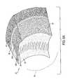
- FIG. 6Aa schematic view of glenohumeral joint capsule 50 is shown with synovial surface 52 overlying collagen-containing ligament layer 55 .
- the end of the scapulais called the glenoid, and is indicated at 56 having periosteum 58 .
- the jointis partly stabilized by a ring of fibrous cartilage surrounding the glenoid called the labrum (indicated in phantom view at 59 ).
- the surgeonmakes a standard posterior access portal for an endoscope.
- a standard anterior portalthen is created at the upper border of the subscapular is tendon and through the rotator interval.
- a sleeve or cannula disposed through the anterior portalallows for introduction of electrode array 5 of the present invention.
- the joint capsuleis prepared for standard arthroscopic fluid inflows and outflows, although such fluids are an optional aspect of the procedure described herein.
- the joint capsule(humeral head not shown) has lax ligament portions indicated at band 60 , such as may be caused by an acute-event injury and result in a unidirectional instability.
- the collagen ligament complexvaries in thickness within the joint capsule, e.g., with thick area 62 A and thin area 62 B (ligament thickness exaggerated for clarity).
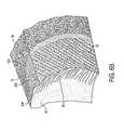
- FIG. 6Bshows in sectional view the depth of capsular ligaments targeted for collagen shrinkage, the area targeted for treatment extending from the synovial surface to the periosteum across the lax portion.
- Electrode-array 5may be introduced into the working space with a suitable instrument, e.g., a grasper, and its position is adjusted until surface 12 is positioned in contact with the capsular surface overlying the collagenous ligament tissue targeted for treatment, i.e., underlying band 60 .
- a suitable instrumente.g., a grasper
- the surgeonmay use sponges 70 (shown in phantom view) or other formable material to retain electrode array 5 in position relative to the humeral head (not shown) and the capsular surface.
- the surgeonthen identifies which pair of electrodes 20 A- 20 C and 22 A- 22 C best span band 60 of tissue targeted for treatment. For example, in FIG. 6C, electrode 20 C (with overlying visual indicator mark “C”) and electrode 22 A (with overlying visual indicator mark “1”) are best positioned in the joint capsule to deliver the desired thermal treatment. The surgeon accordingly selects the appropriate controls on the control panel 45 of RF source 40 for RF delivery to the selected pair of electrodes.
- FIG. 6Dthe joint capsule is shown with arrows 125 indicating the path of the RF current flowing between the selected pair of bi-polar electrodes.
- RF energyflows between electrode 22 A and electrode 20 C and through the tissue in contact with intermediate channeling electrode 25 .
- the RF currentgenerally flows through the collagenous tissue directly under channeling electrode 25 (in band 60 ) that is targeted for treatment along similar “directed paths” for the entire time the electrodes are activated.
- the current flowis in a constant state of flux.
- the channeling electrode of the present inventiongenerally confines the RF current path to the tissue region proximate to conductive element as indicated by arrows 125 . This is highly desirable because stray RF current flow between the bipolar electrodes is largely eliminated, thereby providing higher current density (energy density) in the targeted tissue with lower RF power levels.
- the RF currenttravels generally parallel to channeling electrode 25 , thereby heating the entire depth of collagen tissue and developing a fairly uniform thermal gradient from capsular surface 52 to periosteum 58 .
- This aspect of the inventionis to be contrasted with previously known mono-polar RF delivery, wherein the capsular surface receives excess heat (possibly ablating surface 52 ) and RF current flow between the probe and ground plate is perpendicular to the surface, or random.
- FIG. 6Eshows the joint capsule after shrinking collagen in ligament 55 with the capsular surface shifted toward the humeral head (not shown) along band 60 (electrode array 5 is shown in phantom view and the extent of capsular shift is exaggerated for purposes of illustration).
- the method of the present inventionthus utilizes a stationary electrode (rather than a painting technique), with the bi-polar electrodes and channeling electrode pressed against capsular surface 52 .
- RF currentis applied for times ranging between 5 seconds and 180 seconds at powers in a range of 0.5 to 25 watts, more preferably 2 to 20 watts, and still more preferably, 2 to 10 watts.
- the duration of RF current for low-rate collagen shrinkagemore preferably ranges from 10 seconds to 120 seconds, and still more preferably, from 20 seconds to 60 seconds.
- the longer time intervals provided by the present inventionallow “low-rate” collagen shrinkage, affording the surgeon sufficient time to evaluate the extent of capsular shrinkage and to terminate RF energy delivery based on observation.
- the surgeonsimply may terminate the low-level RF power at any time during capsule shrinkage to gauge the correct amount of shrinkage. After shrinking targeted ligament tissue in the a first location, the surgeon then may move electrode array 5 to a second location.
- applications of the electrode array of the present inventionmay be generalized to deliver controlled levels of radiofrequency energy to subsurface tissues at other locations in a body for a variety of therapeutic purposes, such as for bio-stimulation or bio-excitation purposes.
Landscapes
- Health & Medical Sciences (AREA)
- Surgery (AREA)
- Engineering & Computer Science (AREA)
- Life Sciences & Earth Sciences (AREA)
- Biomedical Technology (AREA)
- Otolaryngology (AREA)
- Nuclear Medicine, Radiotherapy & Molecular Imaging (AREA)
- Plasma & Fusion (AREA)
- Physics & Mathematics (AREA)
- Heart & Thoracic Surgery (AREA)
- Medical Informatics (AREA)
- Molecular Biology (AREA)
- Animal Behavior & Ethology (AREA)
- General Health & Medical Sciences (AREA)
- Public Health (AREA)
- Veterinary Medicine (AREA)
- Surgical Instruments (AREA)
Abstract
Description
Claims (11)
Priority Applications (4)
| Application Number | Priority Date | Filing Date | Title |
|---|---|---|---|
| US10/141,273US6689129B2 (en) | 1998-02-27 | 2002-05-08 | RF electrode array for low-rate collagen shrinkage in capsular shift procedures and methods of use |
| US10/758,777US20040147916A1 (en) | 1998-02-27 | 2004-01-16 | RF electrode array for low-rate collagen shrinkage in capsular shift procedures and methods of use |
| US11/650,887US7585297B2 (en) | 1998-02-27 | 2007-01-08 | RF electrode array for low-rate collagen shrinkage in capsular shift procedures and methods of use |
| US12/584,514US20100004649A1 (en) | 1998-02-27 | 2009-09-08 | RF Electrode array for low-rate collagen shrinkage in capsular shift procedures and methods of use |
Applications Claiming Priority (4)
| Application Number | Priority Date | Filing Date | Title |
|---|---|---|---|
| US7619998P | 1998-02-27 | 1998-02-27 | |
| US09/257,359US6169926B1 (en) | 1998-02-27 | 1999-02-25 | RF electrode array for low-rate collagen shrinkage in capsular shift procedures and methods of use |
| US09/750,548US20010001127A1 (en) | 1998-02-27 | 2000-12-28 | RF electrode array for low-rate collagen shrinkage in capsular shift procedures and methods of use |
| US10/141,273US6689129B2 (en) | 1998-02-27 | 2002-05-08 | RF electrode array for low-rate collagen shrinkage in capsular shift procedures and methods of use |
Related Parent Applications (1)
| Application Number | Title | Priority Date | Filing Date |
|---|---|---|---|
| US09/750,548ContinuationUS20010001127A1 (en) | 1998-02-27 | 2000-12-28 | RF electrode array for low-rate collagen shrinkage in capsular shift procedures and methods of use |
Related Child Applications (1)
| Application Number | Title | Priority Date | Filing Date |
|---|---|---|---|
| US10/758,777DivisionUS20040147916A1 (en) | 1998-02-27 | 2004-01-16 | RF electrode array for low-rate collagen shrinkage in capsular shift procedures and methods of use |
Publications (2)
| Publication Number | Publication Date |
|---|---|
| US20020133214A1 US20020133214A1 (en) | 2002-09-19 |
| US6689129B2true US6689129B2 (en) | 2004-02-10 |
Family
ID=26757782
Family Applications (6)
| Application Number | Title | Priority Date | Filing Date |
|---|---|---|---|
| US09/257,359Expired - Fee RelatedUS6169926B1 (en) | 1998-02-27 | 1999-02-25 | RF electrode array for low-rate collagen shrinkage in capsular shift procedures and methods of use |
| US09/750,548AbandonedUS20010001127A1 (en) | 1998-02-27 | 2000-12-28 | RF electrode array for low-rate collagen shrinkage in capsular shift procedures and methods of use |
| US10/141,273Expired - Fee RelatedUS6689129B2 (en) | 1998-02-27 | 2002-05-08 | RF electrode array for low-rate collagen shrinkage in capsular shift procedures and methods of use |
| US10/758,777AbandonedUS20040147916A1 (en) | 1998-02-27 | 2004-01-16 | RF electrode array for low-rate collagen shrinkage in capsular shift procedures and methods of use |
| US11/650,887Expired - Fee RelatedUS7585297B2 (en) | 1998-02-27 | 2007-01-08 | RF electrode array for low-rate collagen shrinkage in capsular shift procedures and methods of use |
| US12/584,514AbandonedUS20100004649A1 (en) | 1998-02-27 | 2009-09-08 | RF Electrode array for low-rate collagen shrinkage in capsular shift procedures and methods of use |
Family Applications Before (2)
| Application Number | Title | Priority Date | Filing Date |
|---|---|---|---|
| US09/257,359Expired - Fee RelatedUS6169926B1 (en) | 1998-02-27 | 1999-02-25 | RF electrode array for low-rate collagen shrinkage in capsular shift procedures and methods of use |
| US09/750,548AbandonedUS20010001127A1 (en) | 1998-02-27 | 2000-12-28 | RF electrode array for low-rate collagen shrinkage in capsular shift procedures and methods of use |
Family Applications After (3)
| Application Number | Title | Priority Date | Filing Date |
|---|---|---|---|
| US10/758,777AbandonedUS20040147916A1 (en) | 1998-02-27 | 2004-01-16 | RF electrode array for low-rate collagen shrinkage in capsular shift procedures and methods of use |
| US11/650,887Expired - Fee RelatedUS7585297B2 (en) | 1998-02-27 | 2007-01-08 | RF electrode array for low-rate collagen shrinkage in capsular shift procedures and methods of use |
| US12/584,514AbandonedUS20100004649A1 (en) | 1998-02-27 | 2009-09-08 | RF Electrode array for low-rate collagen shrinkage in capsular shift procedures and methods of use |
Country Status (1)
| Country | Link |
|---|---|
| US (6) | US6169926B1 (en) |
Cited By (12)
| Publication number | Priority date | Publication date | Assignee | Title |
|---|---|---|---|---|
| US20040254622A1 (en)* | 1998-05-20 | 2004-12-16 | Shadduck John H. | Surgical instruments and techniques for treating gastro-esophageal reflux disease |
| US7537595B2 (en) | 2001-12-12 | 2009-05-26 | Tissuelink Medical, Inc. | Fluid-assisted medical devices, systems and methods |
| US7604635B2 (en) | 2000-03-06 | 2009-10-20 | Salient Surgical Technologies, Inc. | Fluid-assisted medical devices, systems and methods |
| US7645277B2 (en) | 2000-09-22 | 2010-01-12 | Salient Surgical Technologies, Inc. | Fluid-assisted medical device |
| US7727232B1 (en) | 2004-02-04 | 2010-06-01 | Salient Surgical Technologies, Inc. | Fluid-assisted medical devices and methods |
| US20100211060A1 (en)* | 2009-02-13 | 2010-08-19 | Cutera, Inc. | Radio frequency treatment of subcutaneous fat |
| US7811282B2 (en) | 2000-03-06 | 2010-10-12 | Salient Surgical Technologies, Inc. | Fluid-assisted electrosurgical devices, electrosurgical unit with pump and methods of use thereof |
| US7815634B2 (en) | 2000-03-06 | 2010-10-19 | Salient Surgical Technologies, Inc. | Fluid delivery system and controller for electrosurgical devices |
| US20110111937A1 (en)* | 2007-06-07 | 2011-05-12 | St. Marys Box Company | Article forming paper wrapping device |
| US7951148B2 (en) | 2001-03-08 | 2011-05-31 | Salient Surgical Technologies, Inc. | Electrosurgical device having a tissue reduction sensor |
| US7998140B2 (en) | 2002-02-12 | 2011-08-16 | Salient Surgical Technologies, Inc. | Fluid-assisted medical devices, systems and methods |
| US8475455B2 (en) | 2002-10-29 | 2013-07-02 | Medtronic Advanced Energy Llc | Fluid-assisted electrosurgical scissors and methods |
Families Citing this family (44)
| Publication number | Priority date | Publication date | Assignee | Title |
|---|---|---|---|---|
| US7229436B2 (en)* | 1996-01-05 | 2007-06-12 | Thermage, Inc. | Method and kit for treatment of tissue |
| US6413255B1 (en)* | 1999-03-09 | 2002-07-02 | Thermage, Inc. | Apparatus and method for treatment of tissue |
| US7141049B2 (en) | 1999-03-09 | 2006-11-28 | Thermage, Inc. | Handpiece for treatment of tissue |
| US7022121B2 (en) | 1999-03-09 | 2006-04-04 | Thermage, Inc. | Handpiece for treatment of tissue |
| US6091995A (en) | 1996-11-08 | 2000-07-18 | Surx, Inc. | Devices, methods, and systems for shrinking tissues |
| US6169926B1 (en)* | 1998-02-27 | 2001-01-02 | James A. Baker | RF electrode array for low-rate collagen shrinkage in capsular shift procedures and methods of use |
| US20020156471A1 (en)* | 1999-03-09 | 2002-10-24 | Stern Roger A. | Method for treatment of tissue |
| US20040215235A1 (en)* | 1999-11-16 | 2004-10-28 | Barrx, Inc. | Methods and systems for determining physiologic characteristics for treatment of the esophagus |
| WO2001035846A1 (en) | 1999-11-16 | 2001-05-25 | Ganz Robert A | System and method of treating abnormal tissue in the human esophagus |
| US20060095032A1 (en) | 1999-11-16 | 2006-05-04 | Jerome Jackson | Methods and systems for determining physiologic characteristics for treatment of the esophagus |
| US20030236489A1 (en)* | 2002-06-21 | 2003-12-25 | Baxter International, Inc. | Method and apparatus for closed-loop flow control system |
| US7250047B2 (en)* | 2002-08-16 | 2007-07-31 | Lumenis Ltd. | System and method for treating tissue |
| US7566333B2 (en)* | 2003-08-11 | 2009-07-28 | Electromedical Associates Llc | Electrosurgical device with floating-potential electrode and methods of using the same |
| US7563261B2 (en)* | 2003-08-11 | 2009-07-21 | Electromedical Associates Llc | Electrosurgical device with floating-potential electrodes |
| US7160294B2 (en)* | 2003-09-02 | 2007-01-09 | Curon Medical, Inc. | Systems and methods for treating hemorrhoids |
| US7613523B2 (en)* | 2003-12-11 | 2009-11-03 | Apsara Medical Corporation | Aesthetic thermal sculpting of skin |
| US7150745B2 (en) | 2004-01-09 | 2006-12-19 | Barrx Medical, Inc. | Devices and methods for treatment of luminal tissue |
| EP2301471A1 (en) | 2004-04-01 | 2011-03-30 | The General Hospital Corporation | Method and apparatus for dermatological treatment and tissue reshaping |
| US8357154B2 (en)* | 2004-07-20 | 2013-01-22 | Microline Surgical, Inc. | Multielectrode electrosurgical instrument |
| US7536225B2 (en)* | 2005-01-21 | 2009-05-19 | Ams Research Corporation | Endo-pelvic fascia penetrating heating systems and methods for incontinence treatment |
| US8702694B2 (en) | 2005-11-23 | 2014-04-22 | Covidien Lp | Auto-aligning ablating device and method of use |
| US7997278B2 (en) | 2005-11-23 | 2011-08-16 | Barrx Medical, Inc. | Precision ablating method |
| US7959627B2 (en) | 2005-11-23 | 2011-06-14 | Barrx Medical, Inc. | Precision ablating device |
| US7920926B2 (en)* | 2005-12-09 | 2011-04-05 | Apsara Medical Corporation | Method and apparatus for carrying out the controlled heating of tissue in the region of dermis |
| KR100799524B1 (en)* | 2006-02-28 | 2008-01-31 | 전용규 | Applicator of Skin Care Device |
| WO2008005477A2 (en)* | 2006-07-05 | 2008-01-10 | Bovie Medical | Apparatus and method for skin tightening and corrective forming |
| US8177784B2 (en) | 2006-09-27 | 2012-05-15 | Electromedical Associates, Llc | Electrosurgical device having floating potential electrode and adapted for use with a resectoscope |
| US20080097557A1 (en)* | 2006-10-19 | 2008-04-24 | Apsara Medical Corporation | Method and apparatus for carrying out the controlled heating of tissue in the region of dermis |
| US8475452B2 (en)* | 2007-02-21 | 2013-07-02 | Electromedical Associates, Llc | Instruments and methods for thermal tissue treatment |
| US8641711B2 (en) | 2007-05-04 | 2014-02-04 | Covidien Lp | Method and apparatus for gastrointestinal tract ablation for treatment of obesity |
| US8784338B2 (en) | 2007-06-22 | 2014-07-22 | Covidien Lp | Electrical means to normalize ablational energy transmission to a luminal tissue surface of varying size |
| WO2009009443A1 (en) | 2007-07-06 | 2009-01-15 | Barrx Medical, Inc. | Method and apparatus for gastrointestinal tract ablation to achieve loss of persistent and/or recurrent excess body weight following a weight-loss operation |
| CN102688092B (en) | 2007-07-06 | 2015-04-22 | 柯惠有限合伙公司 | Ablation in the gastrointestinal tract to achieve hemostasis and eradicate lesions with a propensity for bleeding |
| US8646460B2 (en)* | 2007-07-30 | 2014-02-11 | Covidien Lp | Cleaning device and methods |
| US8273012B2 (en) | 2007-07-30 | 2012-09-25 | Tyco Healthcare Group, Lp | Cleaning device and methods |
| WO2009131928A1 (en)* | 2008-04-21 | 2009-10-29 | Electromedical Associates Llc | Devices and methods for ablating and removing a tissue mass |
| US8992521B2 (en) | 2010-04-22 | 2015-03-31 | Electromedical Associates, Llc | Flexible electrosurgical ablation and aspiration electrode with beveled active surface |
| US9643255B2 (en) | 2010-04-22 | 2017-05-09 | Electromedical Associates, Llc | Flexible electrosurgical ablation and aspiration electrode with beveled active surface |
| WO2011133767A1 (en) | 2010-04-22 | 2011-10-27 | Electromedical Associates, Llc | Flexible electrosurgical ablation and aspiration electrode with beveled active surface |
| JP2013526343A (en) | 2010-05-11 | 2013-06-24 | エレクトロメディカル・アソシエイツ・リミテッド・ライアビリティ・カンパニー | Brazing electrosurgical device |
| US10278774B2 (en) | 2011-03-18 | 2019-05-07 | Covidien Lp | Selectively expandable operative element support structure and methods of use |
| US9888954B2 (en) | 2012-08-10 | 2018-02-13 | Cook Medical Technologies Llc | Plasma resection electrode |
| US9161802B2 (en)* | 2013-01-03 | 2015-10-20 | Solta Medical, Inc. | Patterned electrodes for tissue treatment systems |
| US11896823B2 (en) | 2017-04-04 | 2024-02-13 | Btl Healthcare Technologies A.S. | Method and device for pelvic floor tissue treatment |
Citations (12)
| Publication number | Priority date | Publication date | Assignee | Title |
|---|---|---|---|---|
| US5269780A (en) | 1990-10-12 | 1993-12-14 | Delma Elektro- Und Medizinische Apparatebau Gesellschaft Mbh | Electro-surgical devices |
| US5290287A (en) | 1991-09-11 | 1994-03-01 | Richard Wolf Gmbh | Endoscopic coagulation forceps |
| US5443463A (en) | 1992-05-01 | 1995-08-22 | Vesta Medical, Inc. | Coagulating forceps |
| US5458596A (en) | 1994-05-06 | 1995-10-17 | Dorsal Orthopedic Corporation | Method and apparatus for controlled contraction of soft tissue |
| US5697927A (en) | 1992-12-01 | 1997-12-16 | Cardiac Pathways Corporation | Catheter for RF ablation with cooled electrode and apparatus for use therewith |
| US5702390A (en) | 1996-03-12 | 1997-12-30 | Ethicon Endo-Surgery, Inc. | Bioplar cutting and coagulation instrument |
| USH1745H (en) | 1995-09-29 | 1998-08-04 | Paraschac; Joseph F. | Electrosurgical clamping device with insulation limited bipolar electrode |
| US5833690A (en) | 1993-07-22 | 1998-11-10 | Ethicon, Inc. | Electrosurgical device and method |
| US6001093A (en) | 1993-10-15 | 1999-12-14 | Ep Technologies, Inc. | Systems and methods for creating long, thin lesions in body tissue |
| US6035238A (en) | 1997-08-13 | 2000-03-07 | Surx, Inc. | Noninvasive devices, methods, and systems for shrinking of tissues |
| US6073052A (en) | 1996-11-15 | 2000-06-06 | Zelickson; Brian D. | Device and method for treatment of gastroesophageal reflux disease |
| US6169926B1 (en) | 1998-02-27 | 2001-01-02 | James A. Baker | RF electrode array for low-rate collagen shrinkage in capsular shift procedures and methods of use |
- 1999
- 1999-02-25USUS09/257,359patent/US6169926B1/ennot_activeExpired - Fee Related
- 2000
- 2000-12-28USUS09/750,548patent/US20010001127A1/ennot_activeAbandoned
- 2002
- 2002-05-08USUS10/141,273patent/US6689129B2/ennot_activeExpired - Fee Related
- 2004
- 2004-01-16USUS10/758,777patent/US20040147916A1/ennot_activeAbandoned
- 2007
- 2007-01-08USUS11/650,887patent/US7585297B2/ennot_activeExpired - Fee Related
- 2009
- 2009-09-08USUS12/584,514patent/US20100004649A1/ennot_activeAbandoned
Patent Citations (12)
| Publication number | Priority date | Publication date | Assignee | Title |
|---|---|---|---|---|
| US5269780A (en) | 1990-10-12 | 1993-12-14 | Delma Elektro- Und Medizinische Apparatebau Gesellschaft Mbh | Electro-surgical devices |
| US5290287A (en) | 1991-09-11 | 1994-03-01 | Richard Wolf Gmbh | Endoscopic coagulation forceps |
| US5443463A (en) | 1992-05-01 | 1995-08-22 | Vesta Medical, Inc. | Coagulating forceps |
| US5697927A (en) | 1992-12-01 | 1997-12-16 | Cardiac Pathways Corporation | Catheter for RF ablation with cooled electrode and apparatus for use therewith |
| US5833690A (en) | 1993-07-22 | 1998-11-10 | Ethicon, Inc. | Electrosurgical device and method |
| US6001093A (en) | 1993-10-15 | 1999-12-14 | Ep Technologies, Inc. | Systems and methods for creating long, thin lesions in body tissue |
| US5458596A (en) | 1994-05-06 | 1995-10-17 | Dorsal Orthopedic Corporation | Method and apparatus for controlled contraction of soft tissue |
| USH1745H (en) | 1995-09-29 | 1998-08-04 | Paraschac; Joseph F. | Electrosurgical clamping device with insulation limited bipolar electrode |
| US5702390A (en) | 1996-03-12 | 1997-12-30 | Ethicon Endo-Surgery, Inc. | Bioplar cutting and coagulation instrument |
| US6073052A (en) | 1996-11-15 | 2000-06-06 | Zelickson; Brian D. | Device and method for treatment of gastroesophageal reflux disease |
| US6035238A (en) | 1997-08-13 | 2000-03-07 | Surx, Inc. | Noninvasive devices, methods, and systems for shrinking of tissues |
| US6169926B1 (en) | 1998-02-27 | 2001-01-02 | James A. Baker | RF electrode array for low-rate collagen shrinkage in capsular shift procedures and methods of use |
Cited By (24)
| Publication number | Priority date | Publication date | Assignee | Title |
|---|---|---|---|---|
| US20100042091A1 (en)* | 1998-05-20 | 2010-02-18 | Mederi Therapeutics, Inc. | Surgical instruments and techniques for treating gastro-esophageal reflux disease |
| US7008419B2 (en) | 1998-05-20 | 2006-03-07 | Shadduck John H | Surgical instruments and techniques for treating gastro-esophageal reflux disease |
| US20060149224A1 (en)* | 1998-05-20 | 2006-07-06 | Shadduck John H | Surgical instruments and techniques for treating gastro-esophageal reflux disease |
| US20070142831A1 (en)* | 1998-05-20 | 2007-06-21 | Shadduck John H | Surgical Instruments And Techniques For Treating Gastro-Esophageal Reflux Disease |
| US7507239B2 (en) | 1998-05-20 | 2009-03-24 | Shadduck John H | Surgical instruments and techniques for treating gastro-esophageal reflux disease |
| US8556952B2 (en) | 1998-05-20 | 2013-10-15 | Mederi Therapeutics Inc. | Surgical instruments and techniques for treating gastro-esophageal reflux disease |
| US20040254622A1 (en)* | 1998-05-20 | 2004-12-16 | Shadduck John H. | Surgical instruments and techniques for treating gastro-esophageal reflux disease |
| US20100191237A1 (en)* | 1998-05-20 | 2010-07-29 | Shadduck John H | Surgical instruments and techniques for treating gastro-esophageal reflux disease |
| US8038670B2 (en) | 2000-03-06 | 2011-10-18 | Salient Surgical Technologies, Inc. | Fluid-assisted medical devices, systems and methods |
| US7815634B2 (en) | 2000-03-06 | 2010-10-19 | Salient Surgical Technologies, Inc. | Fluid delivery system and controller for electrosurgical devices |
| US8361068B2 (en) | 2000-03-06 | 2013-01-29 | Medtronic Advanced Energy Llc | Fluid-assisted electrosurgical devices, electrosurgical unit with pump and methods of use thereof |
| US8048070B2 (en) | 2000-03-06 | 2011-11-01 | Salient Surgical Technologies, Inc. | Fluid-assisted medical devices, systems and methods |
| US7604635B2 (en) | 2000-03-06 | 2009-10-20 | Salient Surgical Technologies, Inc. | Fluid-assisted medical devices, systems and methods |
| US7811282B2 (en) | 2000-03-06 | 2010-10-12 | Salient Surgical Technologies, Inc. | Fluid-assisted electrosurgical devices, electrosurgical unit with pump and methods of use thereof |
| US7651494B2 (en) | 2000-09-22 | 2010-01-26 | Salient Surgical Technologies, Inc. | Fluid-assisted medical device |
| US7645277B2 (en) | 2000-09-22 | 2010-01-12 | Salient Surgical Technologies, Inc. | Fluid-assisted medical device |
| US7951148B2 (en) | 2001-03-08 | 2011-05-31 | Salient Surgical Technologies, Inc. | Electrosurgical device having a tissue reduction sensor |
| US7537595B2 (en) | 2001-12-12 | 2009-05-26 | Tissuelink Medical, Inc. | Fluid-assisted medical devices, systems and methods |
| US7998140B2 (en) | 2002-02-12 | 2011-08-16 | Salient Surgical Technologies, Inc. | Fluid-assisted medical devices, systems and methods |
| US8475455B2 (en) | 2002-10-29 | 2013-07-02 | Medtronic Advanced Energy Llc | Fluid-assisted electrosurgical scissors and methods |
| US8075557B2 (en) | 2004-02-04 | 2011-12-13 | Salient Surgical Technologies, Inc. | Fluid-assisted medical devices and methods |
| US7727232B1 (en) | 2004-02-04 | 2010-06-01 | Salient Surgical Technologies, Inc. | Fluid-assisted medical devices and methods |
| US20110111937A1 (en)* | 2007-06-07 | 2011-05-12 | St. Marys Box Company | Article forming paper wrapping device |
| US20100211060A1 (en)* | 2009-02-13 | 2010-08-19 | Cutera, Inc. | Radio frequency treatment of subcutaneous fat |
Also Published As
| Publication number | Publication date |
|---|---|
| US20070118192A1 (en) | 2007-05-24 |
| US20010001127A1 (en) | 2001-05-10 |
| US20100004649A1 (en) | 2010-01-07 |
| US20020133214A1 (en) | 2002-09-19 |
| US7585297B2 (en) | 2009-09-08 |
| US6169926B1 (en) | 2001-01-02 |
| US20040147916A1 (en) | 2004-07-29 |
Similar Documents
| Publication | Publication Date | Title |
|---|---|---|
| US6689129B2 (en) | RF electrode array for low-rate collagen shrinkage in capsular shift procedures and methods of use | |
| US6618626B2 (en) | Apparatus and methods for protecting the axillary nerve during thermal capsullorhaphy | |
| JP3741725B2 (en) | Device for controlled contraction of soft tissue | |
| US20240050145A1 (en) | Ablation System, Clamp and Method of Use | |
| NL1004269C2 (en) | RF method and device for depth controlled soft tissue ablation. | |
| US5895386A (en) | Bipolar coagulation apparatus and method for arthroscopy | |
| US8512335B2 (en) | High frequency alternating current medical device with self-limiting conductive material and method | |
| Fanton | Arthroscopic electrothermal surgeryof the shoulder | |
| US7094215B2 (en) | Systems and methods for electrosurgical tissue contraction | |
| US7442193B2 (en) | Electrically conductive/insulative over-shoe for tissue fusion | |
| US20060064086A1 (en) | Bipolar forceps with multiple electrode array end effector assembly | |
| US20080234673A1 (en) | Multi-electrode instruments | |
| US20030014050A1 (en) | Electrode for electrosurgical ablation of tissue | |
| US20110166563A1 (en) | Medical heating device and method with self-limiting electrical heating element | |
| US20050187599A1 (en) | Method and apparatus for controlled contraction of soft tissue | |
| WO1999017690A1 (en) | Systems and methods for electrosurgical tissue contraction | |
| MXPA00008132A (en) | Systems and methods for electrosurgical spine surgery. | |
| AU2011218612B2 (en) | Method of Straddling an Intraosseous Nerve | |
| US20050288663A1 (en) | Method and apparatus for substantial uniform ablation about a bipolar array of electrodes | |
| Blankenship | PHYSICAL MODALITIES ELECTROSURCERY, ELECTROCAUTERY AND ELECTROLYSIS. | |
| Brill | Energy systems in laparoscopy | |
| US20240390057A1 (en) | Pulsed field ablation apparatus and related methods | |
| Brill | 6 CHAPTER ENERGY SYSTEMS IN LAPAROSCOPY | |
| Carr-Locke¹ et al. | 12 Principles of Electrosurgery | |
| Pasic et al. | Energy Systems in Laparoscopy |
Legal Events
| Date | Code | Title | Description |
|---|---|---|---|
| FEPP | Fee payment procedure | Free format text:PAT HOLDER NO LONGER CLAIMS SMALL ENTITY STATUS, ENTITY STATUS SET TO UNDISCOUNTED (ORIGINAL EVENT CODE: STOL); ENTITY STATUS OF PATENT OWNER: SMALL ENTITY | |
| REFU | Refund | Free format text:REFUND - SURCHARGE, PETITION TO ACCEPT PYMT AFTER EXP, UNINTENTIONAL (ORIGINAL EVENT CODE: R2551); ENTITY STATUS OF PATENT OWNER: SMALL ENTITY | |
| FPAY | Fee payment | Year of fee payment:4 | |
| AS | Assignment | Owner name:RESPIRATORY DIAGNOSTIC, INC., WASHINGTON Free format text:ASSIGNMENT OF ASSIGNORS INTEREST;ASSIGNOR:CURON MEDICAL, INC. BY JOHN T. KENDALL, TRUSTEE;REEL/FRAME:022034/0702 Effective date:20070413 Owner name:RESPIRATORY DIAGNOSTIC, INC.,WASHINGTON Free format text:ASSIGNMENT OF ASSIGNORS INTEREST;ASSIGNOR:CURON MEDICAL, INC. BY JOHN T. KENDALL, TRUSTEE;REEL/FRAME:022034/0702 Effective date:20070413 | |
| AS | Assignment | Owner name:MEDERI THERAPEUTICS, INC., CONNECTICUT Free format text:ASSIGNMENT OF ASSIGNORS INTEREST;ASSIGNOR:RESPIRATORY DIAGNOSTIC, INC.;REEL/FRAME:022597/0080 Effective date:20080912 | |
| FEPP | Fee payment procedure | Free format text:PAT HOLDER CLAIMS SMALL ENTITY STATUS, ENTITY STATUS SET TO SMALL (ORIGINAL EVENT CODE: LTOS); ENTITY STATUS OF PATENT OWNER: SMALL ENTITY | |
| REFU | Refund | Free format text:REFUND - PAYMENT OF MAINTENANCE FEE, 8TH YEAR, LARGE ENTITY (ORIGINAL EVENT CODE: R1552); ENTITY STATUS OF PATENT OWNER: SMALL ENTITY | |
| FPAY | Fee payment | Year of fee payment:8 | |
| AS | Assignment | Owner name:HORIZON CREDIT II LLC, CONNECTICUT Free format text:SECURITY INTEREST;ASSIGNOR:MEDERI THERAPEUTICS INC.;REEL/FRAME:036252/0728 Effective date:20150730 | |
| REMI | Maintenance fee reminder mailed | ||
| LAPS | Lapse for failure to pay maintenance fees | ||
| STCH | Information on status: patent discontinuation | Free format text:PATENT EXPIRED DUE TO NONPAYMENT OF MAINTENANCE FEES UNDER 37 CFR 1.362 | |
| FP | Lapsed due to failure to pay maintenance fee | Effective date:20160210 | |
| AS | Assignment | Owner name:MEDERI RF, LLC, TEXAS Free format text:ASSIGNMENT OF ASSIGNORS INTEREST;ASSIGNOR:HORIZON CREDIT II LLC;REEL/FRAME:046069/0567 Effective date:20180424 Owner name:HORIZON CREDIT II LLC, CONNECTICUT Free format text:ASSIGNMENT OF ASSIGNORS INTEREST;ASSIGNOR:MEDERI THERAPEUTICS INC.;REEL/FRAME:046076/0317 Effective date:20180424 |