US6689019B2 - Exercise machine - Google Patents
Exercise machineDownload PDFInfo
- Publication number
- US6689019B2 US6689019B2US09/823,362US82336201AUS6689019B2US 6689019 B2US6689019 B2US 6689019B2US 82336201 AUS82336201 AUS 82336201AUS 6689019 B2US6689019 B2US 6689019B2
- Authority
- US
- United States
- Prior art keywords
- user
- foot
- cam
- striding
- exercise
- Prior art date
- Legal status (The legal status is an assumption and is not a legal conclusion. Google has not performed a legal analysis and makes no representation as to the accuracy of the status listed.)
- Expired - Lifetime, expires
Links
Images


Classifications
- A—HUMAN NECESSITIES
- A63—SPORTS; GAMES; AMUSEMENTS
- A63B—APPARATUS FOR PHYSICAL TRAINING, GYMNASTICS, SWIMMING, CLIMBING, OR FENCING; BALL GAMES; TRAINING EQUIPMENT
- A63B22/00—Exercising apparatus specially adapted for conditioning the cardio-vascular system, for training agility or co-ordination of movements
- A63B22/0015—Exercising apparatus specially adapted for conditioning the cardio-vascular system, for training agility or co-ordination of movements with an adjustable movement path of the support elements
- A63B22/0017—Exercising apparatus specially adapted for conditioning the cardio-vascular system, for training agility or co-ordination of movements with an adjustable movement path of the support elements the adjustment being controlled by movement of the user
- A—HUMAN NECESSITIES
- A63—SPORTS; GAMES; AMUSEMENTS
- A63B—APPARATUS FOR PHYSICAL TRAINING, GYMNASTICS, SWIMMING, CLIMBING, OR FENCING; BALL GAMES; TRAINING EQUIPMENT
- A63B21/00—Exercising apparatus for developing or strengthening the muscles or joints of the body by working against a counterforce, with or without measuring devices
- A63B21/00058—Mechanical means for varying the resistance
- A63B21/00069—Setting or adjusting the resistance level; Compensating for a preload prior to use, e.g. changing length of resistance or adjusting a valve
- A—HUMAN NECESSITIES
- A63—SPORTS; GAMES; AMUSEMENTS
- A63B—APPARATUS FOR PHYSICAL TRAINING, GYMNASTICS, SWIMMING, CLIMBING, OR FENCING; BALL GAMES; TRAINING EQUIPMENT
- A63B21/00—Exercising apparatus for developing or strengthening the muscles or joints of the body by working against a counterforce, with or without measuring devices
- A63B21/15—Arrangements for force transmissions
- A63B21/151—Using flexible elements for reciprocating movements, e.g. ropes or chains
- A63B21/154—Using flexible elements for reciprocating movements, e.g. ropes or chains using special pulley-assemblies
- A—HUMAN NECESSITIES
- A63—SPORTS; GAMES; AMUSEMENTS
- A63B—APPARATUS FOR PHYSICAL TRAINING, GYMNASTICS, SWIMMING, CLIMBING, OR FENCING; BALL GAMES; TRAINING EQUIPMENT
- A63B21/00—Exercising apparatus for developing or strengthening the muscles or joints of the body by working against a counterforce, with or without measuring devices
- A63B21/40—Interfaces with the user related to strength training; Details thereof
- A63B21/4027—Specific exercise interfaces
- A63B21/4033—Handles, pedals, bars or platforms
- A63B21/4034—Handles, pedals, bars or platforms for operation by feet
- A—HUMAN NECESSITIES
- A63—SPORTS; GAMES; AMUSEMENTS
- A63B—APPARATUS FOR PHYSICAL TRAINING, GYMNASTICS, SWIMMING, CLIMBING, OR FENCING; BALL GAMES; TRAINING EQUIPMENT
- A63B21/00—Exercising apparatus for developing or strengthening the muscles or joints of the body by working against a counterforce, with or without measuring devices
- A63B21/40—Interfaces with the user related to strength training; Details thereof
- A63B21/4027—Specific exercise interfaces
- A63B21/4033—Handles, pedals, bars or platforms
- A63B21/4035—Handles, pedals, bars or platforms for operation by hand
- A—HUMAN NECESSITIES
- A63—SPORTS; GAMES; AMUSEMENTS
- A63B—APPARATUS FOR PHYSICAL TRAINING, GYMNASTICS, SWIMMING, CLIMBING, OR FENCING; BALL GAMES; TRAINING EQUIPMENT
- A63B21/00—Exercising apparatus for developing or strengthening the muscles or joints of the body by working against a counterforce, with or without measuring devices
- A63B21/40—Interfaces with the user related to strength training; Details thereof
- A63B21/4041—Interfaces with the user related to strength training; Details thereof characterised by the movements of the interface
- A63B21/4049—Rotational movement
- A—HUMAN NECESSITIES
- A63—SPORTS; GAMES; AMUSEMENTS
- A63B—APPARATUS FOR PHYSICAL TRAINING, GYMNASTICS, SWIMMING, CLIMBING, OR FENCING; BALL GAMES; TRAINING EQUIPMENT
- A63B22/00—Exercising apparatus specially adapted for conditioning the cardio-vascular system, for training agility or co-ordination of movements
- A63B22/0002—Exercising apparatus specially adapted for conditioning the cardio-vascular system, for training agility or co-ordination of movements involving an exercising of arms
- A63B22/001—Exercising apparatus specially adapted for conditioning the cardio-vascular system, for training agility or co-ordination of movements involving an exercising of arms by simultaneously exercising arms and legs, e.g. diagonally in anti-phase
- A—HUMAN NECESSITIES
- A63—SPORTS; GAMES; AMUSEMENTS
- A63B—APPARATUS FOR PHYSICAL TRAINING, GYMNASTICS, SWIMMING, CLIMBING, OR FENCING; BALL GAMES; TRAINING EQUIPMENT
- A63B22/00—Exercising apparatus specially adapted for conditioning the cardio-vascular system, for training agility or co-ordination of movements
- A63B22/0015—Exercising apparatus specially adapted for conditioning the cardio-vascular system, for training agility or co-ordination of movements with an adjustable movement path of the support elements
- A63B22/0023—Exercising apparatus specially adapted for conditioning the cardio-vascular system, for training agility or co-ordination of movements with an adjustable movement path of the support elements the inclination of the main axis of the movement path being adjustable, e.g. the inclination of an endless band
- A—HUMAN NECESSITIES
- A63—SPORTS; GAMES; AMUSEMENTS
- A63B—APPARATUS FOR PHYSICAL TRAINING, GYMNASTICS, SWIMMING, CLIMBING, OR FENCING; BALL GAMES; TRAINING EQUIPMENT
- A63B22/00—Exercising apparatus specially adapted for conditioning the cardio-vascular system, for training agility or co-ordination of movements
- A63B22/0025—Particular aspects relating to the orientation of movement paths of the limbs relative to the body; Relative relationship between the movements of the limbs
- A—HUMAN NECESSITIES
- A63—SPORTS; GAMES; AMUSEMENTS
- A63B—APPARATUS FOR PHYSICAL TRAINING, GYMNASTICS, SWIMMING, CLIMBING, OR FENCING; BALL GAMES; TRAINING EQUIPMENT
- A63B22/00—Exercising apparatus specially adapted for conditioning the cardio-vascular system, for training agility or co-ordination of movements
- A63B22/04—Exercising apparatus specially adapted for conditioning the cardio-vascular system, for training agility or co-ordination of movements with movable multiple steps, i.e. more than one step per limb, e.g. steps mounted on endless loops, endless ladders
- A—HUMAN NECESSITIES
- A63—SPORTS; GAMES; AMUSEMENTS
- A63B—APPARATUS FOR PHYSICAL TRAINING, GYMNASTICS, SWIMMING, CLIMBING, OR FENCING; BALL GAMES; TRAINING EQUIPMENT
- A63B22/00—Exercising apparatus specially adapted for conditioning the cardio-vascular system, for training agility or co-ordination of movements
- A63B22/06—Exercising apparatus specially adapted for conditioning the cardio-vascular system, for training agility or co-ordination of movements with support elements performing a rotating cycling movement, i.e. a closed path movement
- A63B22/0664—Exercising apparatus specially adapted for conditioning the cardio-vascular system, for training agility or co-ordination of movements with support elements performing a rotating cycling movement, i.e. a closed path movement performing an elliptic movement
- A—HUMAN NECESSITIES
- A63—SPORTS; GAMES; AMUSEMENTS
- A63B—APPARATUS FOR PHYSICAL TRAINING, GYMNASTICS, SWIMMING, CLIMBING, OR FENCING; BALL GAMES; TRAINING EQUIPMENT
- A63B23/00—Exercising apparatus specially adapted for particular parts of the body
- A63B23/035—Exercising apparatus specially adapted for particular parts of the body for limbs, i.e. upper or lower limbs, e.g. simultaneously
- A63B23/03575—Apparatus used for exercising upper and lower limbs simultaneously
- A63B23/03591—Upper and lower limb moving in phase, i.e. right foot moving in the same direction as the right hand
- A—HUMAN NECESSITIES
- A63—SPORTS; GAMES; AMUSEMENTS
- A63B—APPARATUS FOR PHYSICAL TRAINING, GYMNASTICS, SWIMMING, CLIMBING, OR FENCING; BALL GAMES; TRAINING EQUIPMENT
- A63B22/00—Exercising apparatus specially adapted for conditioning the cardio-vascular system, for training agility or co-ordination of movements
- A63B22/0025—Particular aspects relating to the orientation of movement paths of the limbs relative to the body; Relative relationship between the movements of the limbs
- A63B2022/0038—One foot moving independently from the other, i.e. there is no link between the movements of the feet
- A—HUMAN NECESSITIES
- A63—SPORTS; GAMES; AMUSEMENTS
- A63B—APPARATUS FOR PHYSICAL TRAINING, GYMNASTICS, SWIMMING, CLIMBING, OR FENCING; BALL GAMES; TRAINING EQUIPMENT
- A63B22/00—Exercising apparatus specially adapted for conditioning the cardio-vascular system, for training agility or co-ordination of movements
- A63B22/0025—Particular aspects relating to the orientation of movement paths of the limbs relative to the body; Relative relationship between the movements of the limbs
- A63B2022/0041—Particular aspects relating to the orientation of movement paths of the limbs relative to the body; Relative relationship between the movements of the limbs one hand moving independently from the other hand, i.e. there is no link between the movements of the hands
- A—HUMAN NECESSITIES
- A63—SPORTS; GAMES; AMUSEMENTS
- A63B—APPARATUS FOR PHYSICAL TRAINING, GYMNASTICS, SWIMMING, CLIMBING, OR FENCING; BALL GAMES; TRAINING EQUIPMENT
- A63B22/00—Exercising apparatus specially adapted for conditioning the cardio-vascular system, for training agility or co-ordination of movements
- A63B22/0025—Particular aspects relating to the orientation of movement paths of the limbs relative to the body; Relative relationship between the movements of the limbs
- A63B2022/0043—Particular aspects relating to the orientation of movement paths of the limbs relative to the body; Relative relationship between the movements of the limbs the movements of the limbs of one body half being synchronised, e.g. the left arm moving in the same direction as the left leg
- A—HUMAN NECESSITIES
- A63—SPORTS; GAMES; AMUSEMENTS
- A63B—APPARATUS FOR PHYSICAL TRAINING, GYMNASTICS, SWIMMING, CLIMBING, OR FENCING; BALL GAMES; TRAINING EQUIPMENT
- A63B22/00—Exercising apparatus specially adapted for conditioning the cardio-vascular system, for training agility or co-ordination of movements
- A63B22/06—Exercising apparatus specially adapted for conditioning the cardio-vascular system, for training agility or co-ordination of movements with support elements performing a rotating cycling movement, i.e. a closed path movement
- A63B22/0605—Exercising apparatus specially adapted for conditioning the cardio-vascular system, for training agility or co-ordination of movements with support elements performing a rotating cycling movement, i.e. a closed path movement performing a circular movement, e.g. ergometers
- A63B2022/0611—Particular details or arrangement of cranks
- A63B2022/0623—Cranks of adjustable length
- A—HUMAN NECESSITIES
- A63—SPORTS; GAMES; AMUSEMENTS
- A63B—APPARATUS FOR PHYSICAL TRAINING, GYMNASTICS, SWIMMING, CLIMBING, OR FENCING; BALL GAMES; TRAINING EQUIPMENT
- A63B22/00—Exercising apparatus specially adapted for conditioning the cardio-vascular system, for training agility or co-ordination of movements
- A63B22/06—Exercising apparatus specially adapted for conditioning the cardio-vascular system, for training agility or co-ordination of movements with support elements performing a rotating cycling movement, i.e. a closed path movement
- A63B22/0664—Exercising apparatus specially adapted for conditioning the cardio-vascular system, for training agility or co-ordination of movements with support elements performing a rotating cycling movement, i.e. a closed path movement performing an elliptic movement
- A63B2022/067—Exercising apparatus specially adapted for conditioning the cardio-vascular system, for training agility or co-ordination of movements with support elements performing a rotating cycling movement, i.e. a closed path movement performing an elliptic movement with crank and handles being on opposite sides of the exercising apparatus with respect to the frontal body-plane of the user, e.g. the crank is behind and handles are in front of the user
- A—HUMAN NECESSITIES
- A63—SPORTS; GAMES; AMUSEMENTS
- A63B—APPARATUS FOR PHYSICAL TRAINING, GYMNASTICS, SWIMMING, CLIMBING, OR FENCING; BALL GAMES; TRAINING EQUIPMENT
- A63B71/00—Games or sports accessories not covered in groups A63B1/00 - A63B69/00
- A63B71/0054—Features for injury prevention on an apparatus, e.g. shock absorbers
- A63B2071/0063—Shock absorbers
- A—HUMAN NECESSITIES
- A63—SPORTS; GAMES; AMUSEMENTS
- A63B—APPARATUS FOR PHYSICAL TRAINING, GYMNASTICS, SWIMMING, CLIMBING, OR FENCING; BALL GAMES; TRAINING EQUIPMENT
- A63B21/00—Exercising apparatus for developing or strengthening the muscles or joints of the body by working against a counterforce, with or without measuring devices
- A63B21/005—Exercising apparatus for developing or strengthening the muscles or joints of the body by working against a counterforce, with or without measuring devices using electromagnetic or electric force-resisters
- A63B21/0051—Exercising apparatus for developing or strengthening the muscles or joints of the body by working against a counterforce, with or without measuring devices using electromagnetic or electric force-resisters using eddy currents induced in moved elements, e.g. by permanent magnets
- A—HUMAN NECESSITIES
- A63—SPORTS; GAMES; AMUSEMENTS
- A63B—APPARATUS FOR PHYSICAL TRAINING, GYMNASTICS, SWIMMING, CLIMBING, OR FENCING; BALL GAMES; TRAINING EQUIPMENT
- A63B21/00—Exercising apparatus for developing or strengthening the muscles or joints of the body by working against a counterforce, with or without measuring devices
- A63B21/005—Exercising apparatus for developing or strengthening the muscles or joints of the body by working against a counterforce, with or without measuring devices using electromagnetic or electric force-resisters
- A63B21/0053—Exercising apparatus for developing or strengthening the muscles or joints of the body by working against a counterforce, with or without measuring devices using electromagnetic or electric force-resisters using alternators or dynamos
- A—HUMAN NECESSITIES
- A63—SPORTS; GAMES; AMUSEMENTS
- A63B—APPARATUS FOR PHYSICAL TRAINING, GYMNASTICS, SWIMMING, CLIMBING, OR FENCING; BALL GAMES; TRAINING EQUIPMENT
- A63B21/00—Exercising apparatus for developing or strengthening the muscles or joints of the body by working against a counterforce, with or without measuring devices
- A63B21/005—Exercising apparatus for developing or strengthening the muscles or joints of the body by working against a counterforce, with or without measuring devices using electromagnetic or electric force-resisters
- A63B21/0058—Exercising apparatus for developing or strengthening the muscles or joints of the body by working against a counterforce, with or without measuring devices using electromagnetic or electric force-resisters using motors
- A—HUMAN NECESSITIES
- A63—SPORTS; GAMES; AMUSEMENTS
- A63B—APPARATUS FOR PHYSICAL TRAINING, GYMNASTICS, SWIMMING, CLIMBING, OR FENCING; BALL GAMES; TRAINING EQUIPMENT
- A63B21/00—Exercising apparatus for developing or strengthening the muscles or joints of the body by working against a counterforce, with or without measuring devices
- A63B21/008—Exercising apparatus for developing or strengthening the muscles or joints of the body by working against a counterforce, with or without measuring devices using hydraulic or pneumatic force-resisters
- A—HUMAN NECESSITIES
- A63—SPORTS; GAMES; AMUSEMENTS
- A63B—APPARATUS FOR PHYSICAL TRAINING, GYMNASTICS, SWIMMING, CLIMBING, OR FENCING; BALL GAMES; TRAINING EQUIPMENT
- A63B21/00—Exercising apparatus for developing or strengthening the muscles or joints of the body by working against a counterforce, with or without measuring devices
- A63B21/012—Exercising apparatus for developing or strengthening the muscles or joints of the body by working against a counterforce, with or without measuring devices using frictional force-resisters
- A—HUMAN NECESSITIES
- A63—SPORTS; GAMES; AMUSEMENTS
- A63B—APPARATUS FOR PHYSICAL TRAINING, GYMNASTICS, SWIMMING, CLIMBING, OR FENCING; BALL GAMES; TRAINING EQUIPMENT
- A63B21/00—Exercising apparatus for developing or strengthening the muscles or joints of the body by working against a counterforce, with or without measuring devices
- A63B21/22—Resisting devices with rotary bodies
- A63B21/225—Resisting devices with rotary bodies with flywheels
- A—HUMAN NECESSITIES
- A63—SPORTS; GAMES; AMUSEMENTS
- A63B—APPARATUS FOR PHYSICAL TRAINING, GYMNASTICS, SWIMMING, CLIMBING, OR FENCING; BALL GAMES; TRAINING EQUIPMENT
- A63B2220/00—Measuring of physical parameters relating to sporting activity
- A63B2220/30—Speed
- A—HUMAN NECESSITIES
- A63—SPORTS; GAMES; AMUSEMENTS
- A63B—APPARATUS FOR PHYSICAL TRAINING, GYMNASTICS, SWIMMING, CLIMBING, OR FENCING; BALL GAMES; TRAINING EQUIPMENT
- A63B2220/00—Measuring of physical parameters relating to sporting activity
- A63B2220/30—Speed
- A63B2220/36—Speed measurement by electric or magnetic parameters
Definitions
- This inventionrelates generally to exercise equipment, and in particular to stationary elliptical motion striding equipment.
- U.S. Pat. No. 5,242,343, entitled “Stationary Exercise Device,”illustrates an exercise device that includes a pair of foot-engaging links for a striding motion. One end of each foot link is supported for rotational motion about a pivot access, and a second end of each foot link is guided in a reciprocal path of travel. The combination of these two foot link motions permits the user's foot to travel in an inclined, generally oval path of travel. The resulting foot action exercises a large number of muscles through a wide range of motion.
- the exercise deviceincludes a pair of bell cranks, similar to the bell cranks used with bicycle pedals, traveling in identical circular paths 180° apart.
- the circular pathseach have a fixed diameter, which is a function of the fixed length of the bell crank web.
- the first end of each foot linkis pinned to the outer end of one of the bell cranks, and thus also travels in a circular path of a fixed diameter.
- the second ends of the foot linksare either slidingly or rollingly engaged with a linear track, or suspended by a swinging link arm, such that the rotary motion of the first ends of the foot links and the reciprocating motion of the second ends of the foot links, in combination, result in a reciprocating, pseudo-elliptical foot path for the foot pad positioned between the first and second ends of each foot link and on which a user stands.
- the fixed resulting foot pathis a predetermined, machine-defined path that is variable only by manually changing physical parameters of the equipment.
- the exercise devicemay provide a foot action that exercises a large number of muscles through a wide range of motion, it confines the range of motion by limiting the path traveled by the first ends of the foot links to the circular path of the bell cranks.
- One embodiment of the exercise device of the present inventionis distinguished from the known so-called “elliptical” motion exercise machines by providing a fore and aft horizontal component of striding motion that is dynamically user-defined, while providing a vertical component of the motion that is maintained on a predetermined vertically reciprocating path. While the user's foot motion is guided in a generally elliptical path, the present invention provides a dynamically variable stride length, which allows the user to move with a natural stride length, within the range of the manufactured product. Thus, a tall or short user is able to extend or curtail the stride length to match his or her natural stride length, and the stride length desired for the level of exercise being performed.
- the length of the reciprocating pathis dynamically adjusted during the exercise operation without equipment adjustments or stopping the exercise being performed by changes in the length of the stride input by the user at a pair of laterally spaced apart foot engagement members.
- the equipmentautomatically compensates by similarly increasing or decreasing the relative length-wise displacement of the two foot engagement members.
- the length and shape of the reciprocating path followed by the user's feetis dynamically variable as a function of the user's input, without changing physical parameters or settings of the exercise machine.
- the operation of the two foot engagement membersis either dependent or independent depending on the construction of the embodiment of the invention.
- the two foot engagement membersare either operatively interconnected by an interconnection member, or operatively disconnected from one another for independent fore-aft movement.
- one aspect of the inventionuses a cam/cam follower arrangement to minimize or soften the jolting accelerations and decelerations associated with known fixed stride-length exercise machines.
- the camsreact in response to the extended or shortened length of a user's stride.
- a transmission utilizing a speed-up drive mode of resistance and flywheel for inertiais coupled to the reciprocating foot engagement members to further smooth the operation, especially the vertical component of the motion.
- a resistance to the striding motionmay be input under user control to enhance the exercise experience by resisting one or both of the vertical and horizontal components of motion.
- a first foot engagement memberis supported for first and second reciprocating motions within a first substantially vertical plane
- a second foot engagement memberis supported for first and second reciprocating motions within a second substantially vertical plane laterally spaced away from the first plane at a convenient distance to accommodate a human user.
- one of the first and second reciprocating motions of the first foot engagement memberis interdependent with respective first and second reciprocating motions of the second foot engagement member with both of its vertical and horizontal components.
- interdependencyis only with respect to the vertical component.
- the length component of the striding motion practiced by one of the user's legsis independent of the corresponding length component practiced by the user's other leg during exercise.
- the striding motion practicedis the same with respect to the length component as a result of the two foot engagement members being tied together through an interconnection between the foot engagement members, such that a cooperation or “dependency” is maintained between the reciprocating motions of the user's two feet during exercise in the horizontal component.
- the first horizontal component of the reciprocal foot motionis dynamically user-defined by varying the length of the stride input by the user at the respective foot engagement member, without accompanying changes to the physical parameters of the exercise machine.
- the variation in the length of the strideis infinite, within the physical bounds of the exercise machine as manufactured.
- the height of the vertical component of the reciprocal foot motionis also dynamically user-defined by varying the height of the stride input by the user at the respective foot engagement members, also without accompanying changes to the physical parameters of the exercise machine. Accordingly, the variation in the height of the stride is also infinite, within the physical bounds of the specific embodiment of exercise machine.
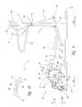
- FIG. 1illustrates one embodiment of the exercise device of the present invention, which includes two foot links pivotally suspended at a forward end from an upright pedestal by respective swing arms and rollably supported at a rearward end by rollers on crank arms, with a resistance device resisting the vertical component of the foot link motion via the rotating crank arms;
- FIG. 2illustrates a first alternative embodiment of the exercise device of the present invention, wherein the two foot links are slidingly supported at the rearward end by linear bearings attached to the crank arms and handles are fixed to the swing arms for upper body exercise;
- FIG. 3illustrates a second alternative embodiment of the exercise device of the present invention similar to the embodiment of FIG. 2, wherein the linear bearings have springs that tend to limit the fore-aft displacement of foot link while easing the jolts that may otherwise accompany reversal of directions;
- FIG. 4illustrates a third alternative embodiment of the exercise device of the present invention, wherein forward and rearward cams at the rearward end of each foot link provide increasing resistance to the horizontal component of foot link motion when the foot links are moved horizontally relative to a central location between the cams;
- FIG. 4Ais an enlarged side view of cams used for the foot links for the embodiment of FIG. 4;
- FIG. 5illustrates a fourth alternative embodiment of the exercise device of the present invention similar to the embodiment of FIG. 4 having a resistance device resisting the horizontal component of the foot link motion but no resistance device for the vertical component;
- FIG. 6illustrates a fifth alternative embodiment of the exercise device of the present invention similar to the embodiments of FIG. 4, wherein separate resistance devices resist the vertical and horizontal components of the foot link motion;
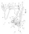
- FIG. 7illustrates a sixth alternative embodiment of the exercise device of the present invention similar to the embodiment of FIG. 4, wherein a single resistance device resists both the vertical and horizontal components of foot link motion;
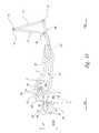
- FIG. 8is an enlarged perspective view of only the foot links, cams and crank arms used in the embodiments of FIGS. 4-7;
- FIG. 9illustrates a path followed by a user using a stride length corresponding to the combined lengths of the crank arms for the embodiments of FIGS. 4-7;
- FIG. 10illustrates a path followed by a user inputting a shorter stride length into the foot engagement pads on the two foot links of the embodiments of FIGS. 4-7;
- FIG. 11illustrates a path followed by a user inputting a longer stride length into the foot engagement pads on the two foot links of the embodiments of FIGS. 4-7;
- FIG. 12illustrates a seventh alternative embodiment of the exercise device of the present invention using an alternative arrangement which provides the vertical component of the foot link motion at the aft ends of the two foot links;
- FIG. 13illustrates an eighth alternative embodiment of the exercise device of the present invention similar to the embodiment of FIG. 4 having interdependent swing arms;
- FIG. 14illustrates a ninth alternative embodiment of the exercise device of the present invention having the forward ends of the two foot links configured to each slidingly or rollingly engage a variably inclinable ramp;
- FIG. 15illustrates a tenth alternative embodiment of the exercise device of the present invention having the forward ends of the two foot links configured to each slidingly or rollingly engage a variably inclinable curved ramp;
- FIG. 16illustrates an eleventh alternative embodiment of the exercise device of the present invention having the forward ends of the two foot links configured to each slidingly or rollingly engage a horizontal surface.
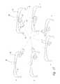
- FIG. 17illustrates a series of positions for one foot link by showing the various positions of a cam as the user moves the foot link through a stride.
- FIG. 18illustrates a twelfth alternative embodiment of the exercise device of the present invention similar to the embodiment of FIG. 13 with the foot links rollably supported at a forward end by the rollers of the crank arms, and supported at a rearward end by the swing arms.
- the present inventionis embodied in an exercise apparatus, indicated generally by reference numeral 2 .
- the apparatus 2primarily provides a lower body exercise while the user stands on the exercise apparatus and moves the user's legs and feet in a variety of pseudo-elliptical striding paths simulating the motion of running, jogging and walking, and the motion of stepping in place, all referred to herein as “striding” with varying amounts of stride horizontal length.
- the pseudo-elliptical striding pathshave both height (vertical) and length (horizontal) components of movement.
- the exercise machine 2accommodates a variety of stride lengths of the user and allows the user to change the length of stride while an exercise is in progress, without requiring any adjustment by the user of equipment settings.
- the exercise machine 2allows an infinite variety of stride length throughout the exercise and, by virtue of the freedom of the mechanism, immediately adjusts in response to the changing stride length of the user.
- stride lengthrefers to the distance between rearward and forward end extents of travel of the user's foot during an exercise repetition.
- the exercise machine 2automatically and immediately moves in response to the stride height used by the user during the exercise and allows infinite user variability of the stride height throughout a large stride height range at any time during the exercise.
- stride heightrefers to the distance between downward and upward end extents of travel of the user's foot during an exercise repetition.
- the exercise machine 2allows the user to vary the stride length independent of the stride height, thereby allowing the user to engage in a natural stride length which can be varied during the exercise without being constrained to a particular stride length and height selected by the manufacturer to be used by all users without variation.
- the exercise machine 2in some embodiments has right and left foot dependency in the rearward and forward directions.
- the resultis an exercise apparatus with improved construction and user feel, and greater flexibility and ease of operation that can simulate all striding-type motions and be comfortably used by users with different natural stride lengths.
- the exercise machine 2can simulate striding-type motions from running with large stride lengths to stepping in place with little or no stride length, with stride length movements that match the natural movements for a user of any size.
- the exercise machine 2automatically follows the stride length input by the user while the exercise is in progress and automatically responds to any changes in stride length input by the user.
- FIG. 1illustrates one embodiment of the exercise machine 2 of the present invention.
- the exercise machineincludes a right foot beam or link 4 and a left foot beam or link 6 , laterally spaced-apart to comfortably receive a user's right and left feet, respectively, thereon for performing a striding movement.
- Right and left foot engagement pads 44 and 46are provided on the right and left foot links 4 and 6 , respectively, between the forward and rearward end portions of the foot links, to receive the right and left feet of the user with the user facing in the forward direction (FWD) indicated on FIG. 1 .
- the right and left foot links 4 and 6each have their forward end portion pivotally suspended from an upright forward support structure or pedestal 8 by respective laterally spaced-apart right and left swing arms 10 and 12 .
- the pedestal 8extends upward from a fixed position on a stationary base 14 , which is configured to rest on a floor surface.
- Each of the swing arms 10 and 12is pivotally suspended about a fixed pivot point on the upright pedestal 8 , the right swing arm 10 being on the right side of the pedestal and the left swing arm 12 being on the left side of the pedestal, by a pivot pin or axle 16 projecting from the right and left sides of the pedestal 8 .
- a bearing journal 18 formed at one end of each swing arm 10 and 12is pivotally mounted on the corresponding free end of the axle 16 , with a rotary bearing or bushing therebetween.
- the swing arms 10 and 12are elongated structures, each having the bearing journal 18 at an upper end, and a respective one of right and left pivotal foot link connections 20 and 22 at a lower end.
- the right and left pivotal foot link connections 20 and 22each provide a pivot connected to the forward end portion of a respective one of the foot links 4 and 6 .
- Pivotal connections 20 and 22are devises attached to the foot link, with a pivot pin extending through the bearing journal, but can have any other suitable hinge or pivot configuration.
- the swing arms 10 and 12are rigid links, such as metal tubes, rods, or plates.
- the swing arms 10 and 12can be formed from flexible links, for example, made of cables, chains, straps or another suitable flexible material.
- the swing arms 10 and 12guide the front end portions of foot links 4 and 6 , at respective pivotal connections 20 and 22 , in a pendulous swinging motion through an arcuate path “A” indicated on FIG. 1 about the axle 16 , having a predetermined radius “A R .” Travel along arcuate path “A” provides a substantially horizontal forward-rearward component of motion simulating that motion of the user's stride. While a small vertical component of motion results as the swing arms swing rearwardly and forwardly, the movement is primarily in the horizontal direction.
- a pair of laterally spaced-apart upright stanchions 24extend upward from the base 14 in a fixed, longitudinally spaced-apart relationship with the pedestal 8 .
- the stanchions 24rotatably support a bell crank assembly 26 , which includes right and left crank arms 28 and 30 rigidly attached to opposite ends of a transverse axle 32 .
- the crank arms 28 and 30travel along identical repeating unidirectional circular paths, but 180 degrees out of phase with one another.
- the crank arms 28 and 30are in fixed relationship to one another, spaced-apart on the opposite, laterally outward sides of the stanchions 24 .
- the axle 32is rotatably supported in a fixed location on the stanchions 24 for rotation about a transverse pivot axis by two rotary bearings or bushings 34 , one secured to each of the stanchions 24 .
- each of the foot links 4 and 6is supported by a distal end 33 of a corresponding one of the crank arms 28 and 30 , at a free end of the crank arm spaced apart from the axle 32 to move down and up with the crank arm.
- the rearward end portions of foot links 4 and 6each rollingly rest atop a roller 36 rotatably mounted on a pin 38 attached to the distal end 33 of a corresponding one of the crank arms 28 and 30 .
- the pins 38extend laterally outward to the right and left sides of the crank arms 28 and 30 , respectively, parallel with the axle 32 .
- the rollers 36 of the crank arms 28 and 30are shaped to laterally retain the foot links 4 and 6 thereon as the foot links reciprocally move freely rearward and forward relative to the rollers during use of the exercise machine 2 .
- This arrangementallows the user to use a stride length during the exercise and change stride length without any machine adjustments while the exercise is in progress.
- the rollers 36are spool shaped with inward and outward end walls 40 to retain the foot links therebetween.
- the rollers 36are mounted on the pins 38 with rotary bearings or bushings (not shown) therebetween.
- the rollers 36thereby combine with rotating crank arms 28 and 30 to allow rearward-forward movement of the foot links 4 and 6 as the crank arms rotate and move the foot links up and down.
- the rollers 36can be replaced with members that slidably support the foot links 4 and 6 thereon.
- a pulley 42is rotatably mounted to and between the stanchions 24 for rotation about the axle 32 and rotationally fixed relative to crank arms 28 and 30 to rotate therewith.
- the pulley 42is rotatably attached to a transmission 58 containing a flywheel that has a sufficiently heavy perimeter weight and is indirectly coupled to crank arms 28 and 30 so as to help turn the crank arms smoothly even when the user momentarily is not supplying a turning force and promote a smooth reversal of foot link directions during the exercise.
- the foot engagement pads 44 and 46are provided on the foot link members 4 and 6 , respectively. Each of the foot engagement pads 44 and 46 is sized to receive the user's corresponding foot thereon during exercise. It is noted that alternatively the foot links 4 and 6 can be constructed without the foot engagement pads 44 and 46 , with the user standing directly on the upper surface of the foot links.
- the exercise machine 2is operated when the user's right and left feet are placed in operative contact with the foot engagement pads 44 and 46 , respectively.
- the userexercises by striding forwardly toward the pedestal 8 .
- Each striding motion of the user's foot, while engaging one of the right and left foot engagement pads 44 and 46pushes a corresponding one of the right or left foot link 4 , 6 rearward away from the pedestal 8 .
- the other foot link 4 , 6tends to be carried forward toward the pedestal by the combined force resulting from the crank arm supporting the other foot link rotating applying a forward force on the foot link, from the swing arms 10 , 12 supporting the foot link tending to pull the foot link forward as it seeks a position hanging straight downward, and from the user's other foot applying a forward force on the foot link as it is moved forward in preparation for the next stride.
- the usernaturally keeps enough weight on the forward moving foot link that the forward moving foot link will be moved no farther or less forward than the user moves the foot on that foot link forward.
- the forward moving foot linkmoves forward with the foot thereon.
- the operation of the exercise machine 2can be started with the foot links 4 and 6 in any position.
- the user's gravitational massi.e., weight
- placed predominantly on the left foot engagement pad 46 of the left foot link 6causes the left foot link 6 to sink downwardly toward base 14 .
- the gravitational force resulting from the user's weight being predominantly on the left foot link 6is transmitted to the left crank arm 30 , thus causing the left crank arm 30 to rotate in the clockwise direction (as view from the right side of the exercise machine in FIG. 1) about the axle 32 as the left foot link 6 moves downwardly toward the base 14 .
- a natural striding motioncauses the user to initially primarily ride the left foot link 6 downward but to push rearwardly more with the left foot against the left foot engagement pad 46 as the user's left foot moves farther downward, much as the user would initially bring the foot into contact with the ground and then push backward against the ground while striding to propel the user forward.
- This movement on the exercise machine 2moves the left foot link 6 rearward.
- the exercise machine 2allows the user to determine the stride length that best suits him, and does not require the same foot path be followed by all users.
- the right and left foot links 4 and 6 of the present inventionmove with the user's feet substantially forward and rearward relative to the rollers 36 of the right and left crank arms 28 and 30 , generally independent of the rotational position of the crank arms.
- the rearward pushing movement of the user's left foot on the left foot engagement pad 46 , and hence on the left foot link 6might be stopped even before the left crank arm 30 reaches the bottom dead center position for a short stride (for almost a stepping or jogging in place movement with very little forward-rearward travel of the foot links), or might be stopped after the left crank arm 30 is in a horizontal position pointing rearward but before reaching the top dead center position (for a long striding movement, especially for a user with long legs and a natural long stride).
- the right crank arm 28When the user does stop pushing rearward with the left foot, the user's weight will be predominantly transferred to the right foot and thrust the right foot engagement pad 44 and the right foot link 4 .
- the right crank arm 28will have been rotated clockwise from the position shown in FIG. 1 to a position 180 degrees from the position of the left crank arm 30 when the user elects to transfer his weight. This might be at or about the top dead center position of the right crank arm 28 for a stepping or jogging in place movement with a very short forward-rearward travel of the foot links 4 and 6 , or near or after a horizontal position where the right crank arm 28 is pointing forward for a long striding movement, or anywhere the right crank arm 28 is located when the weight transfer occurs.
- the weight transfer to the right foot engagement pad 44 and hence the right foot link 4will normally occur for smooth operation when the right crank arm 28 is in a position where downward movement of the right foot link is still possible under the user's weight after the weight transfer occurs.
- the usercontinues the exercise movement, this time with the right foot moving downward and pushing rearward against the right foot engagement pad 44 , while he simultaneous moves his left foot forward while the left foot engagement pad 46 and the left foot link 6 move forward with it.
- the natural striding movement of the right footis to initially primarily ride the right foot link 4 downward but to push rearwardly as the user's right foot moves farther downward.
- crank arms 28 and 30are exchanged, usually some time after the opposite crank arm moves clockwise past the 12 o'clock position and starts rotating downwardly toward base 14 .
- the user's weightis then transferred to the now sinking foot link supported by this crank arm.
- the crank arm rotationcauses the foot link supported by the other crank arm to rise upwardly away from base 14 .
- the foot link supported by this other crank armreaches the position where the user decides to transfer his weight thereto, the process starts over with respect to the now newly weighted foot link.
- the now substantially unweighted foot linkis moved forward, as described above in part by the movement of the crank arm supporting it and by the forward moving foot of the user in a natural striding motion.
- the forcesare transferred to the foot links 4 and 6 via the foot engagement pads 44 and 46 , in the illustrated embodiment of FIG. 1, but may be through any other suitable force transference mechanism affixed to the respective foot links, or directly to the foot links.
- each foot linkWhen the motion of the foot links 4 and 6 occurs, as described above, the forward end portion of each foot link also moves, but with a very different motion.
- the forward end portion of the foot linkexperiences a swinging motion forward or rearward by its connection to a corresponding one of the swing arms 10 and 12 .
- the forward end portions of the foot links 4 and 6travel along the arcuate path “A” shown in FIG. 1 .
- This arcuate motion of the forward end portions of the foot links 4 and 6primarily involves forward and rearward travel of the forward end portions of foot links as the swing arms 10 and 12 pivot, but a small up and down movement of the forward end portions of the foot links also results.
- Each user stridethus moves one of the foot links 4 and 6 rearward and the other is moved forward to position it for the next stride.
- the shifting of the user's weight between the foot links 4 and 6causes the interconnected crank arms 28 and 30 to responsively rotate clockwise, and alternately moves the foot links downward toward and upward from the base 14 , with the movements of the foot links being 180 degrees out of phase with one another.
- the resulting combined downward and upward motions of the foot links as the crank arms 28 and 30 rotate, and the rearward and forward movement of the foot linksresult in the movement of the foot engagement pads 44 and 46 of the foot links 4 and 6 in a cyclical pseudo-elliptical motion path with the actual path shape dependent on how the user chooses to perform his striding exercise.
- a handle bar 54is provided at a predetermined height above the foot links 4 and 6 to assist the user in keeping his balance during operation of the exercise machine 2 .
- a resistance device 56can be utilized if desired to allow the user to selectively increase the effort required by the user to perform a striding motion exercise while on the foot links 4 and 6 and hence control the user energy required for the exercise.
- the resistance device 56is positioned on the base 14 at the rear of the exercise machine 2 adjacent to the stanchions 24 .
- the resistance device 56is coupled to the crank arms 28 and 30 through a series of pulleys and belts forming the mechanical transmission 58 .
- the transmission 58may be deleted if not needed, or formed from any suitable arrangement of belts and pulleys, chains and gears, interconnected shafts, or other mechanisms to transmit the rotational energy of the crank arms 28 and 30 to the resistance device 56 and thereby resist the rotation of the crank arms 28 and 30 with a user selected degree of resistance preferred.
- the exercise machine 2may be alternatively fitted with any one of a variety of known brake mechanisms, or even operated without a brake.
- the resistance device 56is an electrical alternator.
- Other alternative resistance devicesinclude conventional magnetic resistance brakes operating on the eddy current principle, friction brakes such as using frictional contact with the flywheel 42 , other brakes such as air resistance fan brakes and hydrodynamic, i.e., fluid resistance brakes, and other suitable resistance devices.
- Other alternative embodiments of the exercise machine 2are described subsequently herein using other braking configurations.
- An electrical control panel 60is mounted on the exercise machine 2 , atop the pedestal 8 .
- the control panel 60is electrically coupled to control operation of the resistance device 56 , thereby providing remote adjustment thereof, that is accessible to the user during the exercise.
- the control panel 60also provides other exercise related information as is conventional with exercise equipment.
- the exercise machine 2 of the present inventionprovides a variable stride length that is dynamically user adjustable while an exercise is in progress without changing any machine settings, and without the machine changing its own settings, by the simple act of the user stretching the user leg movement into a longer stride or shortening the leg movement into a shorter stride (or stepping motion).
- the exercise machine 2is infinitely adjustable within the physical limitations of the machine, and is therefore naturally variable to complement the different natural stride lengths of taller and shorter users, and even the different stride lengths of users with the same height, and even the different stride lengths a user wishes to use during the course of an exercise.
- the exercise machine 2produces a pseudo-elliptical stride path that is infinitely variable in response to the user input through the movement of his feet when performing an exercise.
- the rearward and forward motion of the foot links 4 and 6is responsive to the left and right rearward and forward feet movements of the user, and operates substantially independent of the vertically reciprocating motion of the foot links produced by the rotation of the crank arms 28 and 30 .
- the respective foot links 4 and 6would be in parallel arrangement, each positioned at the same distance above the base 14 .
- the crank arms 28 and 30would be rotated to the 3 o'clock and 9 o'clock positions, halfway between the top dead center and bottom dead center positions (i.e., the 6 o'clock and 12 o'clock positions).
- the forward-rearward motion of the foot engagement pads 44 and 46 , and hence the foot links 4 and 6is independent of any downward-upward motion of the foot links produced by rotation of the crank arms 28 and 30 , and of the downward and upward motion of the user's feet that does occur during a normal exercise.
- the exercise machineis preferably configured to accommodate even the longest stride of the tallest intended user.
- each of the foot links 4 and 6have their forward ends displaced along the arcuate path “A,” via the pivotal connection of the foot links to the swing arms 10 and 12 described above.
- the displacement of foot links 4 and 6 on respective swing arms 10 and 12forces the forward ends of the foot links farther rearwardly and forwardly of the pedestal 8 along the arcuate path “A,” which tends to progressively lift the forward ends upwardly farther away from base 14 .
- the longer the stridethe more lifting that must occur.
- the user's striding movement when engaging the foot engagement pads 44 and 46inputs energy to the exercise machine 2 which causes the rearward-forward movement of the foot links 4 and 6 , the angular displacement of swing arms 10 and 12 , and the rotation of the crank arms 28 and 30 and the flywheel 42 .
- the userinputs energy to the machine by performing a repetitive left-right striding motion, with the user selected striding length, which may be changed in length by the user at any time during the exercise.
- the resulting rearward and forward movement of the foot links 4 and 6combines with the downward and upward movement of the foot links resulting from the rotation of the crank arms 28 and 30 , to produce a pseudo-elliptical stride path for the feet of the user to follow at each of the respective foot engagement pads 44 and 46 .
- the pseudo-elliptical stride pathis illustrated for an alternative embodiment of the exercise machine 2 in FIGS. 9-11 showing three different user varied stride lengths, and will be described in greater detail below.
- the forward ends of the foot links 4 and 6each has a swinging arcuate motion which also impacts the shape of the pseudo-elliptical stride path produced. The longer the length of the swing arms 10 and 12 used for the exercise machine, the flatter the pseudo-elliptical stride path that results.
- the length of the crank arms 28 and 30is sized at about one-half the normal stride length of adult persons at the lower end of the range of normal stride lengths when exercising. That is, the combined lengths of the diametrically opposed crank arms 28 and 30 is approximately a normal short stride length.
- the crank armsare each 7.5 inches in length, for a combined length of 15 inches.
- the length of the foot links 4 and 6is sized to be long enough to accommodate even much longer normal stride lengths without the rearward ends thereof being moved forward past the rollers 36 on which supported as the foot links move through their pseudo-elliptical stride paths.
- the foot links 4 and 6are maintained in rolling engagement with the rollers 36 rotatably mounted on the distal ends 33 of the crank arms 28 and 30 , and are free to move rearward and forward relative to the rollers, as required to respond to the length of the stride of the user.
- a shorter stridetends to produce a more circular or ovate path than the longer, flatter path produced by a longer stride.
- a stepping or jogging in place movementproduces a generally vertically oriented path with little or no rearward-forward separation between the up and down halves of the path.
- the usercan also exercise on the exercise machine 2 by performing a rearward striding movement (i.e., running backwards while still facing forward toward the pedestal 8 ).
- the userneed only apply his weight to the appropriate foot link to cause the initial rotational movement of the crank arms 28 and 30 to be counterclockwise as viewed from the right side in FIG. 1 .
- the shifting of the user's weight between the foot linksoccurs in the reverse of what has previously been described for forward striding.
- the shape of the pseudo-elliptical stride pathcan also be affected by the size components selected when manufacturing the exercise machine 2 , for example by selecting shorter or longer crank arms 28 and 30 , or swing arms 10 and 12 . Additionally, changes in design can be made to select different placement of the pivotal foot link connections 20 and 22 along the length of the swing arms.
- FIG. 2A first alternative embodiment of the exercise machine 2 is illustrated in FIG. 2, wherein the right and left foot links 4 and 6 are rollingly engaged with respective crank arms 28 and 30 using linear bearings 70 and 72 , respectively.
- at least the rearward end portions of the foot links 4 and 6are formed with tubular or cylindrical shapes and extend through a respective one of the linear bearing 70 and 72 .
- Such linear bearings 70 and 72are well-known in the related arts and are often formed of a sleeve with internal channels for lubricated ball bearings.
- the linear bearings 70 and 72present an alternative to use of the rollers 36 (shown in the embodiment of FIG.
- the linear bearingspermit the unrestricted rearward-forward movement of the foot links 4 and 6 relative to the linear bearings while independently transmitting the downward-upward forces between the foot links and the crank arms 28 and 30 .
- Each of the linear bearings 70 and 72is rotatable attached to the distal end 33 of a corresponding one of the crank arms 28 and 30 . While the linear bearings are used instead of the rollers 36 , the exercise machine 2 illustrated in FIG. 2 generally operates the same as the embodiment illustrated in FIG. 1 .
- the linear bearings 70 and 72may alternatively have other bearing constructions, such as being lined with a low-friction material, such as Teflon® or Nylon, formed with a cylindrical channel sized to slidingly receive the rearward end portions of the foot links 4 and 6 or use roller bearings. Other forms of reduced friction engagement can also be used or the foot links can simply slidably rest upon a pin or other engagement member attached to the crank arms 28 and 30 .
- a low-friction materialsuch as Teflon® or Nylon
- the embodiment of FIG. 2includes a pair of lever arms 74 , each mechanically coupled to a corresponding one of the swing arms 10 and 12 .
- the lever arms 74extend from the respective swing arms 10 and 12 upwardly into the hand gripping range of the average user of the exercise machine 2 , and form rigid mechanical extensions of the swing arms 10 and 12 joined thereto at or about the eye 18 of the swing arms.
- the lever arms 74rotate about the axle 16 of the swing arm to which connected and rotate with the swing arm.
- the user of the exercise machine 2grips one of lever arms 74 in each of his left and right hands, and pulls or pushes on the lever arms 74 in coordination with the rearwardly and forwardly movement of the foot links 4 and 6 , respectively.
- An upper body exerciseis thereby accomplished with the lower body exercise provided by the user striding to move the foot links 4 and 6 .
- FIG. 3A second alternative embodiment of the exercise machine 2 is illustrated in FIG. 3 which is very similar to the embodiment of FIG. 2 .
- linear bearings 76 and 78are used with springs that tend to limit the rearward-forward displacement of foot links 4 and 6 relative to the distal ends 33 of the respective crank arms 28 and 30 , while cushioning the jolts that would otherwise occur when hitting a fixed stop member prior to reversal of the direction of foot link rearward-forward movement.
- Each of the linear bearings 76 and 78uses spaced-apart rearward and forward compression springs 80 captured against rearward and forward motion, respectively, by the closed rearward and forward ends of a bearing housing 82 .
- the rearward end portion of a corresponding one of the foot links 4 and 6extend through the bearing housing and through the rearward and forward springs 80 therein.
- Each of the foot links 4 and 6has a stop 84 rigidly attached thereto, and positioned and sized to engage the inward ends of the springs if the foot link moves rearwardly or forwardly more than a fixed amount relative to the linear bearing.
- the two springs 80 in each linear bearings 76 and 78are spaced apart far enough, and compress sufficiently during operation of the exercise machine as to not unduly limit the largest length of stride permitted for the users when using naturally long strides.
- the springs 80serving as shock absorbers to relieve the jolts that could accompany the reversal of direction of the foot links 4 and 6 if fixed stops were used.
- Other resistance devicesmay also be used to provide increasing resistance to continued movement of the foot links 4 and 6 relative to the distal ends 33 of respective crank arms 28 and 30 .
- the compression springs 80may be replaced with pneumatic or hydraulic springs or dampers, all generally well known in the applicable arts.
- FIG. 4A third alternative embodiment of the exercise machine 2 is shown in FIG. 4 .
- a different arrangementis used to limit the rearward-forward displacement of the foot links 4 and 6 while still providing increasing resistance to continued rearward-forward motion of the foot links 4 and 6 relative to the rollers 36 mounted on the distal ends 33 of the crank arms 28 and 30 as they reach a maximum limit established by the machine's configuration.
- a cam 88is formed on or secured to the rearward end portion of each of the foot links 4 and 6 and configured to cooperate with a corresponding one of the rollers 36 .
- the cams 88each include a downward facing cam surface 90 extending between downwardly projecting forward and rearward stops 92 .
- the surface 90is rollingly engaged by the roller 36 and provides the surface along which the roller rolls during an exercise as the food links 4 and 6 are moved rearwardly and forwardly relative to the roller, as described above for the embodiment of FIG. 1 .
- the cam 88is shown without the roller 3 and the other components of the exercise machine 2 in FIG. 4 A.
- the surface 90has a central portion 89 located about midway between the forward and rearward stops 92 .
- the surface 90curves downward as it extends forward and rearward of the central portion 89 , such that the central portion forms a laterally extending trough or peaked area of the surface in which the roller 36 tends to rest when the exercise machine is not in use and during at least some portions of an exercise using the exercise machine.
- the curvature of the surface 90is relatively flat as it initially extends forward and rearward of the central portion 89 with a radius of curvature much greater than the radius of the roller 36 which engages the surface 90 .
- the surface 90progressively increases in curvature (i.e., the radius of curvature decreases) as it extends closer to the forward and rearward stops 92 , whereat the surface 90 has a radius of curvature slightly larger than the radius of the roller 36 .
- FIG. 8illustrates the crank arms 28 and 30 and their interaction with the cams 88 attached to the foot links 4 and 6 .
- FIG. 8other components of the exercise machine 2 are not illustrated for purposes of clarity.
- roller 36If the roller 36 is not already located at the central portion 89 of the surface 90 , it will be forward or rearward thereof and when the user steps onto the foot engagement pads 44 and 46 of the foot links 4 and 6 , the weight of the user will cause the foot link to move forward or rearward as necessary for the roller 36 rollingly engaging the cam 88 of the foot link to move to the central portion 89 of the surface 90 . In general, this will occur even before the user steps onto the foot links as a result of the weight of the foot links themselves.
- the roller 36tends to seek the peaked central portion 89 of the surface 90 since the surface rearward and forward thereof essentially is a downwardly ramping surface in both directions away from the central portion 89 .
- the roller 36not only tends to roll to this peaked central portion 89 of the surface 90 , but even tends to stay there during an exercise unless the user applies enough rearward or forward force to the respective foot engagement pad 44 , 46 to move the roller rearward or forward along the surface 90 .
- Moving the roller 36 away from the peaked central portion 89 along the ramped surface 90requires energy (essentially like rolling the roller up an upwardly ramping surface).
- the curvature of the surface 90 as it extends away from the central portion 89is selected so that during normal exercise when using an extended stride length, or as will be described, a reduced stride length, it is initially relatively easy to move the foot links 4 and 6 rearward and forward relative to the rollers 36 , but that the energy the user must apply to do so progressively increases as the foot links move farther rearward or forward away from the central portion 89 .
- the radius of curvature of the surface 90 in a central range extending about halfway forward from the peaked central portion 89 and about halfway rearward from the peaked central portionis selected to be sufficiently large relative to the roller 36 so that movement of the foot links 4 and 6 relative to the roller over this central range occurs easily with little horizontal resistance noticeable to the user while exercising.
- the length of this central rangeaccommodates the length of most users normal strides as they normally vary during exercise. While the horizontal resistance experienced by the user over this central range when moving the foot link rearward or forward relative to the roller 36 from the peaked central portion 89 is initially almost imperceptible, it does gradually increase along this central range, and when moving rearward or forward beyond this central range, the horizontal resistance becomes appreciably more noticeable to the user and the rate of change in resistance increases.
- a user striding with an unusually long stridewill tend to move the foot links 4 and 6 beyond the central range.
- the curvature of the surface 90transitions quickly to a radius of curvature closer to the radius of the roller 36 to prevent further movement beyond the stop.
- a typical complete cycle of one of the foot links 4 and 6 for a long stride lengthis illustrated in FIG. 17, showing only the cam 88 as it moves through 6 positions relative to the roller 36 supporting it.
- Position No. 1corresponds to the position of the foot link 6 in FIG. 4 when the user first mounts the exercise machine 2 with the foot links happening to be positioned as shown. The more normal cyclic striding motion with the rearward moving foot of the user pushing rearward occurs between Position Nos. 2 - 6 .
- Position No. 6depending on the length of stride being used, the user would shift his weight to the opposite foot on the other foot link and begin the rearward pushing movement with the opposite foot, generally repeating for that foot link the rearward movement from Position No. 2 through Position No. 6 . It is noted that in Position No. 6 the roller 36 is nearing the forward stop 92 , hence indicating a relatively long stride has been used by the user of the exercise machine.
- a striding motion applied by the user to the foot engagement pads 44 and 46normally drives the respective foot links 4 and 6 rearwardly and forwardly relative to the rollers 36 .
- the rollersmaintain their position nested in the peaked central portion 89 of the surface 90 and the foot links move with the crank arms 28 and 30 , both in the rearward-forward direction and in the downward-upward direction.
- the stride length experiencedwould be twice the length of the cam arms 28 and 30 .
- one of the foot links 4 and 6is moved rearward relative to the roller 36 engaging the cam 88 of that foot link and the roller rolls forward along the surface 90 toward the forward stop 92 thereof.
- the amount of force applied with a rearward-horizontal componentdetermines how far forward the roller 36 moves since increasing energy is required as the roller moves forward along the downwardly curving surface 90 since it results in lifting the body weight of the user on the foot link.
- the amount of lifting requiredis determined by the curvature of the surface 90 along which the roller is rolling. The smaller the radius of curvature, the greater the amount of the rearward-horizontal component of force required since the farther the weight of the user must be lifted up. It is noted that the rearward moving foot link has the user applying the rearward pushing force thereto and tends to carry most of the user's weight.
- the userwhen the user is lengthening his stride by pushing farther rearward with one foot, the user moves the other foot forward by a similar increased amount and causes the foot link that foot is engaging to move forward relative to the roller 36 engaging the cam 88 of that foot link and the roller rolls rearward along the surface 90 toward the rearward stop 92 thereof.
- the amount of force applied with a forward-horizontal component to accomplish this relative movement between the forward moving foot link and the rolleris significantly less than with the rearwardly moving foot link described immediately above. This is because the forward moving foot link is almost completely unweighted and the force needed to lift the foot link is mostly related to the weight of the foot link itself, which is not very large.
- the momentum of the crank arm engaging the forward moving foot link and its direction of rotationtend to drive the foot link forward even without much, if any, help of the forward moving foot of the user.
- the userwill tend to shift his weight and begin the next stride due to the sensation felt with the rearward pushing leg, rather than because of any sensation felt with the forward moving leg which mostly just moves forward along with the forwardly moving foot link.
- the left and right swing arms 10 and 12are interconnected to produce a left-right dependency with respect to the rearward-forward swinging motion thereof.
- the rearward pushing movement on the rearward moving foot linkdrives the forward moving foot link forward without requiring any force applied by the user's forward moving foot thereto.
- the stop 92essentially presents a wall to the roller beyond which it cannot pass due to its radius of curvature relative to the radius of the roller.
- the radius of curvature of the surface 90progressively decreases (i.e., the curvature increases) toward the stops 92 , the increased energy the user must input dissuades moving the foot links 4 and 6 relative to the rollers 36 so far as to engage the stops.
- the progressively increasing nature of the force encountered when reaching the end of a long stridetends to train the user to sense and respond to the increasing in force to know when to shift his weight and avoid using overly long stride lengths that might drive the rollers 36 into the stops 92 .
- the usertends to respond to this increase in force subconsciously and it stimulates a weight shift to begin a new stride while well within the physical parameters of the exercise machine 2 as manufactured.
- the additional resistance supplied by the resistance device 56if operating, also tends to discourage overly long stride lengths. Generally, the more resistance the user selects for the resistance device 56 to supply, the shorter the stride used.
- stops 92ensures that the cam 88 securely captures, between its forward and rearward stops 92 , the roller 36 of the one of the crank arms 28 and 30 supporting the foot link 4 , 6 to which the cam is secured.
- the stops 92are spaced longitudinally apart sufficient to allow significant relative rearward and forward motion between the foot link and the roller for the longest stride to be accommodated.
- the foot links 4 and 6 of the embodiment of the exercise machine 2 shown in FIG. 4each have a lowered mid-portion at which the foot engagement pads 44 and 46 are attached. This places the foot engagement pads 44 and 46 closer to the base 14 , making stepping onto the foot links easier.
- a fourth alternative embodiment of the exercise machine 2is shown in FIG. 5 with the above described resistance device 56 mounded at a forward end portion of the base 14 and coupled to resist the rearward-forward movement of the foot links 4 and 6 , rather than the rotation of the crank arms 28 and 30 .
- a conventional mechanical transmission 100is used to connect the resistance device 56 to the foot links 4 and 6 , through the swing arms 10 and 12 .
- the transmission 100includes pulleys and belts with a pulley 102 rigidly mounted on the axle 16 , which is in this embodiment rotatably mounted to the pedestal 8 .
- Each of the swing arms 10 and 12has its bearing journal 18 mounted to a corresponding free end portion of the axle 16 via a ratchet clutch assembly 101 that converts the oscillating swinging motion of swing arms 10 and 12 into a unidirectional rotational motion of the axle 16 .
- This unidirectional rotationis transmitted to the pulley 102 affixed to the axle and engaged by one of the belts of the transmission system 100 .
- the resistance device 56may be used.
- the resistance device 56arranged as shown in FIG. 5, the user experiences a resistance to the input rearward-forward-striding motion and thereby achieves increased exercise.
- the resistance device 56is electrically coupled to the control panel 60 for accepting user commands that control the resistance level of the resistance device.
- the pulley 42 mounted at the rearward end of the base 14is weighted to act as a flywheel to smooth the reciprocating operation of the foot links 4 and 6 , and the rotation of the crank arms 28 and 30 .
- a fifth alternative embodiment of the exercise machine 2is shown in FIG. 6 using two resistance devices 56 , one mounted at the forward end of the base 14 to selectively resist the rearward-forward movement of the foot links 4 and 6 as described above for the embodiment of FIG. 5, and one mounted at the rearward end of the base 14 to selectively resist the rotation of the crank arms 28 and 30 as described above for the embodiment of FIG. 1 .
- Both the fore and aft resistance devices 56are electrically coupled to the user control panel 60 mounted on the pedestal 8 , whereby the user is able to input directions controlling the operation of the resistance devices and thereby the level of each of the fore and aft braking applied.
- FIG. 7A sixth alternative embodiment of the exercise machine 2 is shown in FIG. 7, using a single resistance device 56 mounted at the rearward end of the base 14 but coupled to resist both the rearward-forward movement of the foot links 4 and 6 and the rotation of the crank arms 28 and 30 , much as with the embodiment of FIG. 6 but using a single resistance device.
- the pulley 102is connected by a chain or belt 106 to an idler set of gears or pulleys 112 supported by a pair of stanchions 116 to the forward end of the base 14 .
- the idler set of gears/pulleys 112is connected by a chain or belt 108 to another idler set of gears or pulleys 114 supported by a pair of stanchions 118 to the rearward end of the base 14 .
- the idler gears/pulleys 114are connected by a chain or belt 110 to the resistance device 56 via the transmission 58 . Striding motions input by the user at foot engagement pads 44 and 46 are resisted by the resistance device 56 under the user's control to require a user directed increased effort to perform the striding exercise.
- the single resistance device embodiment describedis just one example of many resistance and transmission configurations possible and contemplated by the invention.
- FIGS. 9 through 11illustrate three of the many pseudo-elliptical stride paths of the foot engagement pads 44 and 46 that may be produced using the exercise machine 2 .
- FIG. 9, for example,illustrates a path 120 followed by a user inputting a stride length into the foot engagement pads 44 and 46 that follows the path traced when the rollers 36 remain in the peaked central portion 89 of the surface 90 of the cams 88 , where the stride length is about twice the length of the crank arms 28 and 30 , as described above.
- FIG. 10illustrates a shortened pseudo-elliptical stride path 122 than shown in FIG. 9, resulting from a shorter than normal stride, which is less than the combined lengths of the crank arms 28 and 30 .
- rollers 36are angularly displaced forward and rearward of the peaked central portion 89 of the surface 90 by an angle ⁇ for the left foot link 6 relative to the corresponding left roller 36 , and by an angle + ⁇ for the right foot link 4 relative to the corresponding right roller 36 .
- FIG. 11illustrates an extended pseudo-elliptical stride path 124 that is longer than the normal stride input by the user, and longer than the combined lengths of crank arms 28 and 30 .
- rollers 36are angularly displaced rearward and forward of the peaked central portion 89 of the surface 90 , to the opposite side thereof than shown in FIG. 10, by an angle + ⁇ for the left foot link 6 relative to the corresponding left roller 36 and an angle ⁇ for the right foot link 4 relative to the corresponding right roller 36 .
- FIG. 12illustrates a seventh alternative embodiment of exercise machine 2 which replaces the crank arms 28 and 30 with a different reciprocating arrangement which provides a purely vertical upward and downward motion at the rearward ends of the foot links 4 and 6 .
- a reciprocator 126 supported on the rearward end portion of the base 14has a pulley or gear 126 rotatable mounted to the stanchions 24 with a flexible member 128 such as a cable or chain passing over the pulley 126 .
- a left side end of the flexible member 128is secured to a left reciprocating member 131 guided by a guide rod 130 a to reciprocate upward and downward, and a right side end of the flexible member 128 is secured to a right reciprocating member 131 guided by a guide rod 130 b to reciprocate upward and downward.
- Each of the reciprocating membershas a sleeve secured thereto and slidably disposed on a corresponding one of the guide rods 130 a and 130 b.
- the left and right side rollers 36which support the cams 88 , and hence the foot links 4 and 6 , are rotatably mounted on spindles of a corresponding one of the left and right reciprocating members 131 for upward and downward movement therewith.
- the shifting of the user's body weight applied to the foot engagement pads 44 and 46is transmitted through the corresponding cams 88 at the rearward end of the corresponding foot links 4 and 6 to the corresponding reciprocating members 131 through the rollers 36 attached thereto to produce reciprocating downward and upward movement of the rearward end portions of the foot links 4 and 6 .
- the rearward-forward movement of the foot links 4 and 6responds to the rearward-forward movement of the user's feet as described above for other embodiments.
- FIG. 12it is easy to operate the exercise machine with a jogging or stepping in place movement with little or no rearward-forward movement, or to produce a stride length of the length desired by the user in response to the movement of the user's legs.
- the exercise machine 2conforms to the stride length selected by the user, rather than restricting the user to the stride path length of the machine, i.e., the exercise machine conforms to the user rather than forcing the user to conform to the machine.
- FIG. 13An eighth embodiment of the exercise machine 2 is shown in FIG. 13 .
- This embodimentis generally the same as the embodiment of FIG. 4 except that the left and right swing arms 10 and 12 are interconnected to produce a left-right dependency with respect to the rearward-forward swinging motion thereof.
- a reciprocator or bell crank assembly 132interconnects the left and right swing arms 10 and 12 .
- the crank assembly 132includes right and left crank arms 134 a and 136 a rigidly attached to opposite ends of a transverse axle 138 rotatably mounted to the pedestal 8 by a bushing or bearing 140 .
- a distal end of each of the crank arms 134 a and 136 ais pivotally coupled to an end of a respective one of arms 134 b and 136 b.
- each of the arms 134 b and 136 bis pivotally coupled to a respective one of the swing arms 10 and 12 by a respective one of pins 142 and 144 .
- This arrangement of crank arms 134 a and 136 a and arms 134 b and 136 bserve as double overhung cranks to interconnect the swinging motion of the swing arms 10 and 12 , such that when a user's striding motion input at foot engagement pads 44 and 46 drives one of the swing arms to swing rearward, the other is caused to swing forward through the action of the crank assembly 132 .
- crank assembly 132coordinates or “matches” the rearward-forward movements of the foot engagement pads 44 and 46 .
- the movement of the right and left lever arms 74is also coordinated with the rearward-forward movements of the foot engagement pads 44 and 46 , although the movement is in the opposite direction.
- the left-right dependencytends to make starting movement of the foot links 4 and 6 in the direction desired for forward or rearward striding easier since the foot link movements are mechanically coordinated and do not require the user to insure proper coordinated movement occurs when first starting an exercise, i.e., if one foot link begins to move rearward, the other must be moved forward.
- There are other mechanisms that may be used for achieving this left-right dependency of the rearward-forward motion of the foot links 4 and 6such as pivoting rocker arm assemblies, reversing rotational hubs about pivoting axes, and flexible members (chain/belt) connected to the swing arms 10 and 12 and traveling around an idler pulley therebetween.
- FIG. 14illustrates a ninth alternative embodiment of the exercise machine 2 .
- the swing arms 10 and 12have been replaced with variably inclinable right and left tracks or ramps 154 to guide the forward ends of the foot links 4 and 6 while they reciprocate rearwardly and forwardly.
- the forward ends of the foot links 4 and 6each have a roller 156 attached thereto and are configured to rollingly engage the corresponding one of the inclined tracks 154 for movement therealong.
- the inclined tracks 154are configured to guide the forward ends of the foot links 4 and 6 in respective reciprocating, angularly upward linear motions very similar to the motion produced by the swing arms 10 and 12 but along a straight path rather than the arcuate path “A” shown in FIG. 1 .
- Other suitable alternative mechanical arrangementsare contemplated for providing guided motion of the forward ends of the foot links 4 and 6 such as having the ends of the foot links slidably engaging a guide track or rail.
- the angle of incline of tracks 154is adjustable relative to base 14 about a hinge 158 .
- the inclination angle ⁇ between the tracks 154 and the base 14is adjustable in response to a user command input at control panel 60 which controls a drive motor 160 connected to raise and lower the tracks 154 via a connector member 162 . Varying the inclination of the tracks 154 (angle ⁇ ) increases and decreases the effort required by the user performing the exercise and changes the shape of the pseudo-elliptical stride path produced at the foot engagement pads 44 and 46 .
- FIG. 15illustrates a tenth alternative embodiment of the exercise machine 2 , wherein the rollers 156 at the forward ends of the foot links 4 and 6 are guided with variably inclinable curved ramps or tracks 174 as the foot links reciprocate rearwardly and forwardly.
- the variably inclinable tracks 174can be used with a rate of curvature that changes along the length of the tracks to control the effort required of the user performing the exercise and the shape of the pseudo-elliptical stride path produced.
- the shape of the tracks 174can be curved to produce the same movement produced by the swing arms 10 and 12 in the earlier described embodiments.
- the angular inclination ⁇ of the curved tracks 174is adjustable relative to base 14 in the embodiment of FIG. 15 about a hinge 178 .
- the inclination angle ⁇ between the tracks 174 and the base 14is adjustable in response to a user command input at the control panel 60 .
- FIG. 16An eleventh alternative embodiment of the exercise machine 2 is shown in FIG. 16 .
- the rollers 156 at the forward ends of the foot links 4 and 6are guided by a horizontal surface portion of the base 14 as the foot links 4 and 6 reciprocate rearwardly and forwardly.
- a sliding member or another suitable mechanical devicecan be mounted on the forward ends of the foot links 4 and 6 for engaging the base 14 or some guide formed in or provided on the base, such as a guide channel, rail or device to restrict lateral movement of the forward ends of the foot links while allowing their rearward-forward movement.
- FIG. 18A twelfth alternative embodiment of the exercise machine 2 is shown in FIG. 18 .
- This embodimentis similar to the embodiment of FIG. 13 except that the forward end portions of the foot links 4 and 6 have the cams 88 and are supported by the crank arms 28 and 30 of the crank assembly 26 , and the rearward end portions of the foot links are supported by the swing arms 10 and 12 .
- the handle bar 54 and the control panel 60are attached to an upward extension of the stanchions 24 , rather than to the upper end portion of the pedestal 8 .
- the foot engagement pads 44 and 46are angled to provide a comfortable feel to the user, but this can also be provided by other means, such as providing a different contour to the foot links 4 and 6 .
Landscapes
- Health & Medical Sciences (AREA)
- General Health & Medical Sciences (AREA)
- Physical Education & Sports Medicine (AREA)
- Cardiology (AREA)
- Vascular Medicine (AREA)
- Orthopedic Medicine & Surgery (AREA)
- Life Sciences & Earth Sciences (AREA)
- Biophysics (AREA)
- Rehabilitation Tools (AREA)
- Confectionery (AREA)
Abstract
Description
Claims (22)
Priority Applications (16)
| Application Number | Priority Date | Filing Date | Title |
|---|---|---|---|
| US09/823,362US6689019B2 (en) | 2001-03-30 | 2001-03-30 | Exercise machine |
| TW091106031ATWI250883B (en) | 2001-03-30 | 2002-03-27 | Exercise machine |
| ES02757879TES2214986T1 (en) | 2001-03-30 | 2002-03-28 | TRAINING MACHINE |
| AT02757879TATE417651T1 (en) | 2001-03-30 | 2002-03-28 | EXERCISE MACHINE |
| DE60230396TDE60230396D1 (en) | 2001-03-30 | 2002-03-28 | PHYSICAL EXERCISE MACHINE |
| CNB028110684ACN1254287C (en) | 2001-03-30 | 2002-03-28 | Exercise machine |
| DE2002757879DE02757879T1 (en) | 2001-03-30 | 2002-03-28 | PHYSICAL EXERCISE MACHINE |
| EP02757879AEP1372794B1 (en) | 2001-03-30 | 2002-03-28 | Exercise machine |
| PCT/US2002/009867WO2002078791A1 (en) | 2001-03-30 | 2002-03-28 | Exercise machine |
| US10/742,702US7341542B2 (en) | 2001-03-30 | 2003-12-19 | Exercise machine |
| US11/767,873US7632219B2 (en) | 2001-03-30 | 2007-06-25 | Exercise machine |
| US12/636,814US7942787B2 (en) | 2001-03-30 | 2009-12-14 | Exercise machine |
| US13/108,704US8323155B2 (en) | 2001-03-30 | 2011-05-16 | Exercise machine |
| US13/692,840US8858403B2 (en) | 2001-03-30 | 2012-12-03 | Exercise machine |
| US14/480,707US9272182B2 (en) | 2001-03-30 | 2014-09-09 | Exercise machine |
| US15/018,329US10201727B2 (en) | 2001-03-30 | 2016-02-08 | Exercise machine |
Applications Claiming Priority (1)
| Application Number | Priority Date | Filing Date | Title |
|---|---|---|---|
| US09/823,362US6689019B2 (en) | 2001-03-30 | 2001-03-30 | Exercise machine |
Related Child Applications (1)
| Application Number | Title | Priority Date | Filing Date |
|---|---|---|---|
| US10/742,702ContinuationUS7341542B2 (en) | 2001-03-30 | 2003-12-19 | Exercise machine |
Publications (2)
| Publication Number | Publication Date |
|---|---|
| US20020142890A1 US20020142890A1 (en) | 2002-10-03 |
| US6689019B2true US6689019B2 (en) | 2004-02-10 |
Family
ID=25238534
Family Applications (8)
| Application Number | Title | Priority Date | Filing Date |
|---|---|---|---|
| US09/823,362Expired - LifetimeUS6689019B2 (en) | 2001-03-30 | 2001-03-30 | Exercise machine |
| US10/742,702Expired - LifetimeUS7341542B2 (en) | 2001-03-30 | 2003-12-19 | Exercise machine |
| US11/767,873Expired - Fee RelatedUS7632219B2 (en) | 2001-03-30 | 2007-06-25 | Exercise machine |
| US12/636,814Expired - Fee RelatedUS7942787B2 (en) | 2001-03-30 | 2009-12-14 | Exercise machine |
| US13/108,704Expired - Fee RelatedUS8323155B2 (en) | 2001-03-30 | 2011-05-16 | Exercise machine |
| US13/692,840Expired - Fee RelatedUS8858403B2 (en) | 2001-03-30 | 2012-12-03 | Exercise machine |
| US14/480,707Expired - Fee RelatedUS9272182B2 (en) | 2001-03-30 | 2014-09-09 | Exercise machine |
| US15/018,329Expired - Fee RelatedUS10201727B2 (en) | 2001-03-30 | 2016-02-08 | Exercise machine |
Family Applications After (7)
| Application Number | Title | Priority Date | Filing Date |
|---|---|---|---|
| US10/742,702Expired - LifetimeUS7341542B2 (en) | 2001-03-30 | 2003-12-19 | Exercise machine |
| US11/767,873Expired - Fee RelatedUS7632219B2 (en) | 2001-03-30 | 2007-06-25 | Exercise machine |
| US12/636,814Expired - Fee RelatedUS7942787B2 (en) | 2001-03-30 | 2009-12-14 | Exercise machine |
| US13/108,704Expired - Fee RelatedUS8323155B2 (en) | 2001-03-30 | 2011-05-16 | Exercise machine |
| US13/692,840Expired - Fee RelatedUS8858403B2 (en) | 2001-03-30 | 2012-12-03 | Exercise machine |
| US14/480,707Expired - Fee RelatedUS9272182B2 (en) | 2001-03-30 | 2014-09-09 | Exercise machine |
| US15/018,329Expired - Fee RelatedUS10201727B2 (en) | 2001-03-30 | 2016-02-08 | Exercise machine |
Country Status (8)
| Country | Link |
|---|---|
| US (8) | US6689019B2 (en) |
| EP (1) | EP1372794B1 (en) |
| CN (1) | CN1254287C (en) |
| AT (1) | ATE417651T1 (en) |
| DE (2) | DE02757879T1 (en) |
| ES (1) | ES2214986T1 (en) |
| TW (1) | TWI250883B (en) |
| WO (1) | WO2002078791A1 (en) |
Cited By (84)
| Publication number | Priority date | Publication date | Assignee | Title |
|---|---|---|---|---|
| US20020035017A1 (en)* | 2000-05-03 | 2002-03-21 | Victor Pertegaz-Esteban | Exercise equipment with multi-positioning handles |
| US20040082444A1 (en)* | 2002-08-08 | 2004-04-29 | Nautilus, Inc. | Dual-direction pulley system |
| US20040132583A1 (en)* | 2001-03-30 | 2004-07-08 | Nautilus, Inc. | Exercise machine |
| US20040248707A1 (en)* | 2003-06-06 | 2004-12-09 | Rodgers Robert E. | Compact variable path exercise apparatus with a relatively long cam surface |
| US20040248710A1 (en)* | 2003-06-06 | 2004-12-09 | Rodgers Robert E. | Exercise apparatus with a variable stride system |
| US20040248704A1 (en)* | 2003-06-06 | 2004-12-09 | Rodgers Robert E. | Compact variable path exercise apparatus |
| US20040248708A1 (en)* | 2003-06-06 | 2004-12-09 | Rodgers Robert E. | Variable stride exercise apparatus |
| US20050026752A1 (en)* | 2003-06-23 | 2005-02-03 | Nautilus, Inc. | Variable stride exercise device |
| US20050124467A1 (en)* | 2003-12-04 | 2005-06-09 | Rodgers Robert E.Jr. | Pendulum striding exercise devices |
| US20050124466A1 (en)* | 2003-12-04 | 2005-06-09 | Rodgers Robert E.Jr. | Pendulum striding exercise apparatus |
| US20050148438A1 (en)* | 2004-01-05 | 2005-07-07 | Raleigh America | Exercise device |
| US20050202939A1 (en)* | 2003-06-23 | 2005-09-15 | Nautilus, Inc. | Variable stride exercise device |
| US20050277519A1 (en)* | 2002-08-06 | 2005-12-15 | Moon Daniel R | Compact Elliptical exercise machine with adjustable stride length |
| US20060003868A1 (en)* | 2003-06-23 | 2006-01-05 | Nautilus, Inc. | Releasable connection mechanism for variable stride exercise devices |
| US7083554B1 (en) | 1997-02-27 | 2006-08-01 | Nautilus, Inc. | Exercise machine with infinite position range limiter and automatic belt tensioning system |
| US20060189445A1 (en)* | 2005-02-09 | 2006-08-24 | Precor, Inc. | Elliptical exercise equipment with stowable arms |
| US7097593B2 (en) | 2003-08-11 | 2006-08-29 | Nautilus, Inc. | Combination of treadmill and stair climbing machine |
| US20060217234A1 (en)* | 2005-03-25 | 2006-09-28 | Rodgers Robert E Jr | Exercise device with flexible support elements |
| US20060234838A1 (en)* | 2005-04-14 | 2006-10-19 | Icon Ip, Inc. | Method and system for varying stride in an elliptical exercise machine |
| US20070021274A1 (en)* | 2005-07-20 | 2007-01-25 | Moon Daniel R | Compact elliptical exercise machine with adjustable stride length |
| US20070087906A1 (en)* | 2003-06-06 | 2007-04-19 | Rodgers Robert E Jr | Variable stride exercise apparatus |
| US7214168B2 (en) | 2003-06-06 | 2007-05-08 | Rodgers Jr Robert E | Variable path exercise apparatus |
| US7244217B2 (en) | 2003-06-06 | 2007-07-17 | Rodgers Jr Robert E | Exercise apparatus that allows user varied stride length |
| US20070219062A1 (en)* | 2006-03-09 | 2007-09-20 | Rodgers Robert E | Translating support assembly systems and methods for use thereof |
| US20070219061A1 (en)* | 2006-03-09 | 2007-09-20 | Rodgers Jr Robert E | Variable geometry flexible support systems and methods for use thereof |
| US20080051258A1 (en)* | 2006-08-22 | 2008-02-28 | Jacob Stewart Schmehl | Elliptical exercise device and methods of use |
| US20080070755A1 (en)* | 2006-09-15 | 2008-03-20 | Mckee Todd | Machines and Methods for Combined and Isolated Upper and Lower Body Workouts |
| US20080125291A1 (en)* | 2006-11-16 | 2008-05-29 | Nautilus, Inc. | Variable stride exercise device |
| US20080161164A1 (en)* | 2006-12-28 | 2008-07-03 | Precor Incorporated | End of travel stop for an exercise device |
| US20090062080A1 (en)* | 2007-08-31 | 2009-03-05 | Guy James K | Stowable arms |
| US20090131228A1 (en)* | 2006-08-02 | 2009-05-21 | Johnson Health Tech Co., Ltd. | Exercise apparatus |
| US20090176625A1 (en)* | 2001-11-13 | 2009-07-09 | Cybex International, Inc. | Exercise Apparatus |
| US20090203501A1 (en)* | 2007-05-10 | 2009-08-13 | Rodgers Jr Robert E | Adjustable Geometry Exercise Devices and Methods for Use Thereof |
| US20090239715A1 (en)* | 2006-08-02 | 2009-09-24 | Johnson Health Tech Co., Ltd. | Exercise apparatus |
| US20100105528A1 (en)* | 2004-06-04 | 2010-04-29 | Christiaan Ditolla | Verticle exercise cycle |
| US7717446B2 (en) | 2006-11-21 | 2010-05-18 | Pt Motion Works, Inc. | Self-propelled vehicle propelled by an elliptical drive train |
| US20100167883A1 (en)* | 2008-12-29 | 2010-07-01 | Precor Incorporated | Exercise device with adaptive curved track motion |
| US20100167880A1 (en)* | 2006-08-02 | 2010-07-01 | Johnson Health Tech Co., Ltd. | Exercise apparatus |
| US20100197466A1 (en)* | 2008-10-15 | 2010-08-05 | Sports Art Industrial Co., Ltd. | Athletic apparatus with non-linear sliding track |
| US20100298101A1 (en)* | 2009-05-19 | 2010-11-25 | Pt Motion Works, Inc. | Adjustable Crank Arms for Elliptical Bike and Method of Use |
| US20100295262A1 (en)* | 2009-05-19 | 2010-11-25 | Pt Motion Works, Inc. | Folding Steering Column for Elliptical Bike and Method of Use |
| US7841968B1 (en)* | 2009-11-04 | 2010-11-30 | Paul William Eschenbach | Free path elliptical exercise apparatus |
| US20100317497A1 (en)* | 2009-06-12 | 2010-12-16 | Yasser Nadim | Exercise device and method of using same |
| US20100317494A1 (en)* | 2009-06-15 | 2010-12-16 | Leao Wang | Method for providing a resistance to an exercise apparatus with an inertia resistance wheel and a resistance-providing apparatus employing the same |
| US7878947B1 (en)* | 2007-05-10 | 2011-02-01 | Rodgers Jr Robert E | Crank system assemblies and methods for use thereof |
| USD633416S1 (en) | 2010-03-17 | 2011-03-01 | Pt Motion Works, Inc. | Elliptical bicycle frame |
| USD633827S1 (en) | 2010-03-17 | 2011-03-08 | Pt Motion Works, Inc. | Elliptical bicycle frame |
| US8061728B2 (en) | 2009-05-19 | 2011-11-22 | Pt Motion Works, Inc. | Interlocking guide tracks for elliptical bike and method of use |
| WO2012055004A1 (en)* | 2010-10-29 | 2012-05-03 | Gym Social Inc. | Exercise machine and pivoting assembly therefor |
| US20130035212A1 (en)* | 2011-08-01 | 2013-02-07 | Jin Chen Chuang | Stationary exercise device |
| US8540609B2 (en)* | 2006-03-13 | 2013-09-24 | Brunswick Corporation | Climber appliance |
| US20140121065A1 (en)* | 2012-10-31 | 2014-05-01 | Icon Health & Fitness, Inc. | Arch Track for Elliptical Exercise Machine |
| US8979714B2 (en)* | 2013-05-07 | 2015-03-17 | Larry D. Miller Trust | Elliptical exercise device |
| US9199116B1 (en)* | 2014-08-25 | 2015-12-01 | Dyaco International Inc. | Exercise device providing adjustable pace length |
| US9636540B2 (en) | 2015-03-10 | 2017-05-02 | True Fitness Technology, Inc. | Adjustable stride elliptical motion exercise machine with large stride variability and fast adjustment |
| US10188890B2 (en) | 2013-12-26 | 2019-01-29 | Icon Health & Fitness, Inc. | Magnetic resistance mechanism in a cable machine |
| US10252109B2 (en) | 2016-05-13 | 2019-04-09 | Icon Health & Fitness, Inc. | Weight platform treadmill |
| US10258828B2 (en) | 2015-01-16 | 2019-04-16 | Icon Health & Fitness, Inc. | Controls for an exercise device |
| US10272317B2 (en) | 2016-03-18 | 2019-04-30 | Icon Health & Fitness, Inc. | Lighted pace feature in a treadmill |
| US10279212B2 (en) | 2013-03-14 | 2019-05-07 | Icon Health & Fitness, Inc. | Strength training apparatus with flywheel and related methods |
| US10293211B2 (en) | 2016-03-18 | 2019-05-21 | Icon Health & Fitness, Inc. | Coordinated weight selection |
| US10343017B2 (en) | 2016-11-01 | 2019-07-09 | Icon Health & Fitness, Inc. | Distance sensor for console positioning |
| US10376736B2 (en) | 2016-10-12 | 2019-08-13 | Icon Health & Fitness, Inc. | Cooling an exercise device during a dive motor runway condition |
| US10426989B2 (en) | 2014-06-09 | 2019-10-01 | Icon Health & Fitness, Inc. | Cable system incorporated into a treadmill |
| US10433612B2 (en) | 2014-03-10 | 2019-10-08 | Icon Health & Fitness, Inc. | Pressure sensor to quantify work |
| US10441844B2 (en) | 2016-07-01 | 2019-10-15 | Icon Health & Fitness, Inc. | Cooling systems and methods for exercise equipment |
| US10471299B2 (en) | 2016-07-01 | 2019-11-12 | Icon Health & Fitness, Inc. | Systems and methods for cooling internal exercise equipment components |
| US10493349B2 (en) | 2016-03-18 | 2019-12-03 | Icon Health & Fitness, Inc. | Display on exercise device |
| US10500473B2 (en) | 2016-10-10 | 2019-12-10 | Icon Health & Fitness, Inc. | Console positioning |
| US10537764B2 (en) | 2015-08-07 | 2020-01-21 | Icon Health & Fitness, Inc. | Emergency stop with magnetic brake for an exercise device |
| US10543395B2 (en) | 2016-12-05 | 2020-01-28 | Icon Health & Fitness, Inc. | Offsetting treadmill deck weight during operation |
| US10549145B2 (en) | 2017-06-30 | 2020-02-04 | Johnson Health Tech Co., Ltd. | Stationary exercise apparatus with variable foot path |
| US10561894B2 (en) | 2016-03-18 | 2020-02-18 | Icon Health & Fitness, Inc. | Treadmill with removable supports |
| US10561877B2 (en) | 2016-11-01 | 2020-02-18 | Icon Health & Fitness, Inc. | Drop-in pivot configuration for stationary bike |
| US10625137B2 (en) | 2016-03-18 | 2020-04-21 | Icon Health & Fitness, Inc. | Coordinated displays in an exercise device |
| US10661114B2 (en) | 2016-11-01 | 2020-05-26 | Icon Health & Fitness, Inc. | Body weight lift mechanism on treadmill |
| US10702736B2 (en) | 2017-01-14 | 2020-07-07 | Icon Health & Fitness, Inc. | Exercise cycle |
| US10729965B2 (en) | 2017-12-22 | 2020-08-04 | Icon Health & Fitness, Inc. | Audible belt guide in a treadmill |
| US10953305B2 (en) | 2015-08-26 | 2021-03-23 | Icon Health & Fitness, Inc. | Strength exercise mechanisms |
| US11154221B2 (en) | 2018-03-23 | 2021-10-26 | International Business Machines Corporation | Diagnosing changes in gait based on flexibility monitoring |
| US11451108B2 (en) | 2017-08-16 | 2022-09-20 | Ifit Inc. | Systems and methods for axial impact resistance in electric motors |
| US12185836B1 (en) | 2022-07-19 | 2025-01-07 | Ronald B. Johnson | Height adjustable desk |
| US12268930B1 (en) | 2022-07-19 | 2025-04-08 | Ronald B. Johnson | Body motion office work platform |
| US12376674B1 (en) | 2023-03-29 | 2025-08-05 | Ronald B. Johnson | Seat incorporated into desk platform |
Families Citing this family (88)
| Publication number | Priority date | Publication date | Assignee | Title |
|---|---|---|---|---|
| US7559879B2 (en) | 2001-04-16 | 2009-07-14 | Brunswick Corporation | Stride adjustment mechanism |
| US6461279B1 (en) | 2001-07-25 | 2002-10-08 | Hai Pin Kuo | Treadmill having dual treads for stepping exercises |
| US7455626B2 (en) | 2001-12-31 | 2008-11-25 | Nautilus, Inc. | Treadmill |
| US7033306B2 (en)* | 2002-10-09 | 2006-04-25 | Jase Graber | Spontaneous symmetrical weight shifting device |
| US7553260B2 (en) | 2003-02-28 | 2009-06-30 | Nautilus, Inc. | Exercise device with treadles |
| US7815549B2 (en)* | 2003-02-28 | 2010-10-19 | Nautilus, Inc. | Control system and method for an exercise apparatus |
| US7517303B2 (en) | 2003-02-28 | 2009-04-14 | Nautilus, Inc. | Upper body exercise and flywheel enhanced dual deck treadmills |
| US7621850B2 (en) | 2003-02-28 | 2009-11-24 | Nautilus, Inc. | Dual deck exercise device |
| US7270626B2 (en) | 2004-01-23 | 2007-09-18 | Octane Fitness, Llc | Exercise equipment with automatic adjustment of stride length and/or stride height based upon direction of foot support rotation |
| US7448986B1 (en) | 2004-02-18 | 2008-11-11 | Octane Fitness, Llc | Exercise equipment with automatic adjustment of stride length and/or stride height based upon the heart rate of a person exercising on the exercise equipment |
| US7361122B2 (en) | 2004-02-18 | 2008-04-22 | Octane Fitness, Llc | Exercise equipment with automatic adjustment of stride length and/or stride height based upon speed of foot support |
| USD518701S1 (en) | 2004-07-09 | 2006-04-11 | Octane Fitness, Llc | Handgrip |
| US7766797B2 (en) | 2004-08-11 | 2010-08-03 | Icon Ip, Inc. | Breakaway or folding elliptical exercise machine |
| US7740563B2 (en) | 2004-08-11 | 2010-06-22 | Icon Ip, Inc. | Elliptical exercise machine with integrated anaerobic exercise system |
| US7704192B2 (en)* | 2005-02-17 | 2010-04-27 | Precor Incorporated | Elliptical exercise equipment with adjustable stride |
| US7264576B2 (en)* | 2005-03-15 | 2007-09-04 | Stamina Products, Inc. | Elliptical exercise device |
| US7300065B2 (en)* | 2005-04-18 | 2007-11-27 | Yair Tal | Body weight-activated scooter |
| US7367926B2 (en)* | 2005-08-01 | 2008-05-06 | Fitness Quest Inc. | Exercise treadmill |
| US20070197345A1 (en)* | 2006-02-13 | 2007-08-23 | Wallace Gregory A | Motivational displays and methods for exercise machine |
| USD547159S1 (en) | 2006-06-23 | 2007-07-24 | Octane Fitness, Llc | Handgrip |
| US7658698B2 (en) | 2006-08-02 | 2010-02-09 | Icon Ip, Inc. | Variable stride exercise device with ramp |
| US7717828B2 (en) | 2006-08-02 | 2010-05-18 | Icon Ip, Inc. | Exercise device with pivoting assembly |
| US9011291B2 (en) | 2011-04-14 | 2015-04-21 | Precor Incorporated | Exercise device path traces |
| US7736279B2 (en)* | 2007-02-20 | 2010-06-15 | Icon Ip, Inc. | One-step foldable elliptical exercise machine |
| US7918766B2 (en) | 2007-03-28 | 2011-04-05 | Brunswick Corporation | Elliptical mechanism |
| US20090029831A1 (en) | 2007-03-30 | 2009-01-29 | Nautilus, Inc. | Device and method for limiting travel in an exercise device, and an exercise device including such a limiting device |
| US7674205B2 (en) | 2007-05-08 | 2010-03-09 | Icon Ip, Inc. | Elliptical exercise machine with adjustable foot motion |
| US7618350B2 (en) | 2007-06-04 | 2009-11-17 | Icon Ip, Inc. | Elliptical exercise machine with adjustable ramp |
| US20090048072A1 (en)* | 2007-08-14 | 2009-02-19 | Jin Chen Chuang | Stationary exerciser |
| US20090048077A1 (en)* | 2007-08-14 | 2009-02-19 | Jin Chen Chuang | Stationary exerciser |
| US20090124463A1 (en)* | 2007-11-08 | 2009-05-14 | Michael Lin | Exerciser having adjustable moving stroke |
| US7811207B2 (en)* | 2008-02-19 | 2010-10-12 | Stearns Kenneth W | Exercise methods and apparatus |
| US7922625B2 (en)* | 2008-12-29 | 2011-04-12 | Precor Incorporated | Adaptive motion exercise device with oscillating track |
| US8556779B2 (en)* | 2008-12-29 | 2013-10-15 | Precor Incorporated | Exercise device with gliding footlink pivot guide |
| US7887465B2 (en)* | 2009-02-06 | 2011-02-15 | Precor Incorporated | Adaptive motion exercise device with plural crank assemblies |
| WO2010120912A2 (en)* | 2009-04-15 | 2010-10-21 | Precor Incorporated | Exercise apparatus with flexible element |
| US8740754B2 (en)* | 2010-01-11 | 2014-06-03 | Larry D. Miller | Adaptive exercise device |
| US8814757B2 (en) | 2010-05-05 | 2014-08-26 | Paul William Eschenbach | Free pace elliptical exercise apparatus |
| US9017223B2 (en) | 2010-05-05 | 2015-04-28 | Paul William Eschenbach | Selective stride elliptical exercise apparatus |
| US8668627B2 (en)* | 2010-05-05 | 2014-03-11 | Paul William Eschenbach | Free terrain elliptical exercise apparatus |
| US8257230B2 (en)* | 2010-12-23 | 2012-09-04 | Zhongshan Yingliang Health Technology Co., Ltd. | Elliptical trainer having two crank assemblies |
| US9144706B1 (en)* | 2011-05-12 | 2015-09-29 | Joseph D Maresh | Exercise apparatus |
| US9597540B2 (en)* | 2012-02-14 | 2017-03-21 | Precor Incorporated | Adaptive motion exercise device |
| US20140024499A1 (en)* | 2012-07-23 | 2014-01-23 | Icon Health & Fitness, Inc. | Elliptical Exercise Device with Vibration Capabilities |
| US9289648B2 (en) | 2012-07-23 | 2016-03-22 | Icon Health & Fitness, Inc. | Treadmill with deck vibration |
| US9278249B2 (en) | 2012-07-23 | 2016-03-08 | Icon Health & Fitness, Inc. | Exercise cycle with vibration capabilities |
| CN102861413B (en)* | 2012-09-27 | 2015-01-28 | 浙江神耀运动器材有限公司 | Pedal device of elliptical machine |
| US8974352B2 (en) | 2012-11-27 | 2015-03-10 | Paul William Eschenbach | Stride maker elliptical exercise apparatus |
| CN104001308B (en)* | 2013-02-25 | 2016-09-07 | 岱宇国际股份有限公司 | Elliptical trainer with variable stroke |
| US9616281B2 (en)* | 2013-02-26 | 2017-04-11 | Hupa International Inc. | Crank for exercise equipment which helps prevent injuries on a rider's ankle during an unexpected drop in speed and assists in avoiding stress on the knees of a rider during exercising |
| US9950209B2 (en) | 2013-03-15 | 2018-04-24 | Nautilus, Inc. | Exercise machine |
| US20140296035A1 (en)* | 2013-03-28 | 2014-10-02 | Leao Wang | Simple harmonic motion exercise device |
| CA2924056C (en)* | 2013-09-11 | 2019-07-02 | Cybex International, Inc. | Exercise apparatus |
| US20150087480A1 (en)* | 2013-09-26 | 2015-03-26 | Leao Wang | Simple harmonic motion exercise device |
| US9254413B2 (en)* | 2013-11-19 | 2016-02-09 | Kun Shan University | Elliptical exerciser |
| US9254412B2 (en)* | 2013-11-19 | 2016-02-09 | Kun Shan University | Elliptical exerciser |
| US9272181B2 (en)* | 2014-04-25 | 2016-03-01 | Precor Incorporated | Selectable stride elliptical |
| US9468795B2 (en) | 2014-04-25 | 2016-10-18 | Precor Incorporated | Selectable stride elliptical |
| US9586085B2 (en)* | 2014-06-04 | 2017-03-07 | Precor Incorporated | Exercise apparatus with non-uniform foot pad transverse spacing |
| TWI535476B (en)* | 2014-06-30 | 2016-06-01 | 力山工業股份有限公司 | Elliptical trainer |
| CN105617607A (en)* | 2014-11-08 | 2016-06-01 | 青岛瑞箭机电工程技术有限公司 | Electric pedaling and stretching device |
| US9457223B2 (en) | 2015-01-27 | 2016-10-04 | Paul William Eschenbach | Stride seeker elliptical exercise apparatus |
| CN105167959B (en)* | 2015-10-12 | 2017-11-17 | 哈尔滨工程大学 | A kind of multi-functional gait rehabilitation trainer |
| US10065062B2 (en) | 2015-10-12 | 2018-09-04 | Precor Incorporated | Exercise apparatus with eddy current rail |
| US10668314B2 (en) | 2015-10-16 | 2020-06-02 | Precor Incorporated | Variable distance eddy current braking system |
| US9649529B1 (en) | 2015-11-23 | 2017-05-16 | Larry D. Miller Trust | Elliptical exercise device with moving control tracks |
| US9511255B1 (en) | 2015-11-23 | 2016-12-06 | Larry D. Miller Trust | Elliptical exercise device with moving control tracks |
| USD795975S1 (en)* | 2016-01-22 | 2017-08-29 | Nautilus, Inc. | Handle |
| USD795974S1 (en)* | 2016-01-22 | 2017-08-29 | Nautilus, Inc. | Handle |
| USD795973S1 (en)* | 2016-01-22 | 2017-08-29 | Nautilus, Inc. | Handle for exercise machine |
| US10625114B2 (en) | 2016-11-01 | 2020-04-21 | Icon Health & Fitness, Inc. | Elliptical and stationary bicycle apparatus including row functionality |
| CN207324022U (en)* | 2016-11-17 | 2018-05-08 | 桐乡创智体育科技有限公司 | Virtual aquatic sports ground-based training system |
| US11033767B2 (en)* | 2017-01-03 | 2021-06-15 | Engen Fitness, Inc. | Guided movement exercise machine |
| US10561891B2 (en)* | 2017-05-26 | 2020-02-18 | Nautilus, Inc. | Exercise machine |
| CN107261403B (en)* | 2017-06-29 | 2019-03-08 | 深圳市龙岗中心医院 | Limb movement rehabilitator |
| EP3628018B1 (en)* | 2017-07-12 | 2021-06-02 | Motiofy AB | Cross-country skiing machine |
| KR101933180B1 (en)* | 2017-09-29 | 2018-12-31 | 신광의료기산업(주) | Whole body exercise device |
| TW201927375A (en) | 2017-12-22 | 2019-07-16 | 美商諾特樂斯公司 | Lateral elliptical trainer |
| CN108671477B (en)* | 2018-03-23 | 2020-03-13 | 苏州东巍网络科技有限公司 | Teenager fitness equipment based on virtual reality technology and using method |
| US10946238B1 (en) | 2018-07-23 | 2021-03-16 | Life Fitness, Llc | Exercise machines having adjustable elliptical striding motion |
| CN109224381B (en)* | 2018-10-09 | 2023-12-08 | 苏州好博医疗器械股份有限公司 | Four-limb linkage mechanism |
| US10709927B1 (en)* | 2018-10-30 | 2020-07-14 | Alfred Sidney Smith, Jr. | Multi-position horizontal elliptical cycle fitness equipment |
| JP6592790B1 (en)* | 2019-03-28 | 2019-10-23 | 靖夫 内川 | Crank rotation drive transmission mechanism |
| US12011638B2 (en) | 2020-03-09 | 2024-06-18 | Life Fitness, Llc | Exercise machines for facilitating elliptical striding motion |
| CN113476789B (en)* | 2021-06-10 | 2023-05-26 | 广州城建职业学院 | Running machine for outdoor square exercise |
| CN113521650B (en)* | 2021-07-12 | 2022-06-21 | 南阳市第二人民医院 | Intracardiac branch of academic or vocational study rehabilitation training device |
| CN114129968B (en)* | 2021-12-02 | 2022-07-15 | 新疆维吾尔自治区人民医院 | A portable and foldable lower limb rehabilitation instrument |
| JP7283831B1 (en) | 2022-12-29 | 2023-05-30 | 康嗣 石井 | walking exercise equipment |
Citations (149)
| Publication number | Priority date | Publication date | Assignee | Title |
|---|---|---|---|---|
| US219439A (en) | 1879-09-09 | Improvement in passive-motion walking-machines | ||
| US2603486A (en) | 1948-07-23 | 1952-07-15 | Joseph Borroughs | Push and pull exerciser |
| US3316898A (en) | 1964-10-23 | 1967-05-02 | James W Brown | Rehabilitation and exercise apparatus |
| US3316899A (en) | 1963-12-19 | 1967-05-02 | Raeder Arthur | Anatomical lacing with actuating means for exercising facial muscles |
| US3432164A (en) | 1967-02-14 | 1969-03-11 | Hugh A Deeks | Exercising machine |
| US3578800A (en) | 1967-10-13 | 1971-05-18 | Paolo Dinepi | Foldable bicycle-type exercising device |
| US3756595A (en) | 1971-04-23 | 1973-09-04 | G Hague | Leg exercising device for simulating ice skating |
| US3759511A (en) | 1971-03-29 | 1973-09-18 | K Gustafson | Adjustable friction type exercising device |
| US4053173A (en) | 1976-03-23 | 1977-10-11 | Chase Sr Douglas | Bicycle |
| US4185622A (en) | 1979-03-21 | 1980-01-29 | Swenson Oscar J | Foot and leg exerciser |
| US4188030A (en) | 1976-10-18 | 1980-02-12 | Repco Limited | Cycle exerciser |
| DE2919494C2 (en) | 1979-05-15 | 1982-12-30 | Christian 7120 Bietigheim-Bissingen Baer | Training device with two cranks supported by a stand |
| US4379566A (en) | 1981-01-26 | 1983-04-12 | Creative Motion Industries, Inc. | Operator powered vehicle |
| US4456276A (en) | 1981-04-15 | 1984-06-26 | Peter Bortolin | Bicycle assembly |
| US4509742A (en) | 1983-06-06 | 1985-04-09 | Cones Charles F | Exercise bicycle |
| US4555109A (en) | 1983-09-14 | 1985-11-26 | Hartmann Joseph C | Exercising machine |
| US4561318A (en) | 1981-10-05 | 1985-12-31 | Schirrmacher Douglas R | Lever power system |
| US4645200A (en) | 1985-05-28 | 1987-02-24 | Hix William R | Isometric exercising device |
| US4679786A (en) | 1986-02-25 | 1987-07-14 | Rodgers Robert E | Universal exercise machine |
| US4720093A (en) | 1984-06-18 | 1988-01-19 | Del Mar Avionics | Stress test exercise device |
| US4786050A (en) | 1986-11-06 | 1988-11-22 | Geschwender Robert C | Exercise machine |
| US4869494A (en) | 1989-03-22 | 1989-09-26 | Lambert Sr Theodore E | Exercise apparatus for the handicapped |
| US4900013A (en) | 1988-01-27 | 1990-02-13 | Rodgers Jr Robert E | Exercise apparatus |
| US4940233A (en) | 1988-02-19 | 1990-07-10 | John Bull | Aerobic conditioning apparatus |
| US4949954A (en) | 1989-05-04 | 1990-08-21 | Hix William R | Jointed bicycle-simulation device for isometric exercise |
| US4949993A (en) | 1989-07-31 | 1990-08-21 | Laguna Tectrix, Inc. | Exercise apparatus having high durability mechanism for user energy transmission |
| US4989857A (en) | 1990-06-12 | 1991-02-05 | Kuo Hai Pin | Stairclimber with a safety speed changing device |
| US5000443A (en) | 1987-09-08 | 1991-03-19 | Weslo, Inc. | Striding exerciser |
| US5039088A (en) | 1990-04-26 | 1991-08-13 | Shifferaw Tessema D | Exercise machine |
| US5039087A (en) | 1990-05-11 | 1991-08-13 | Kuo Hai Pin | Power stairclimber |
| US5078389A (en) | 1991-07-19 | 1992-01-07 | David Chen | Exercise machine with three exercise modes |
| US5094449A (en) | 1990-08-07 | 1992-03-10 | Stearns Kenneth W | Exercise apparatus for abdominal exercises |
| US5094450A (en) | 1990-06-22 | 1992-03-10 | Stearns Kenneth W | Abdominal exercise machine |
| US5131895A (en) | 1988-01-27 | 1992-07-21 | Rogers Jr Robert E | Exercise apparatus |
| US5135447A (en) | 1988-10-21 | 1992-08-04 | Life Fitness | Exercise apparatus for simulating stair climbing |
| US5163888A (en) | 1992-02-25 | 1992-11-17 | Stearns Kenneth W | Exercise apparatus |
| US5186697A (en) | 1989-01-31 | 1993-02-16 | Rennex Brian G | Bi-directional stair/treadmill/reciprocating-pedal exerciser |
| US5242343A (en) | 1992-09-30 | 1993-09-07 | Larry Miller | Stationary exercise device |
| US5279529A (en) | 1992-04-16 | 1994-01-18 | Eschenbach Paul W | Programmed pedal platform exercise apparatus |
| US5290211A (en) | 1992-10-29 | 1994-03-01 | Stearns Technologies, Inc. | Exercise device |
| US5295928A (en) | 1989-01-31 | 1994-03-22 | Rennex Brian G | Bi-directional stair/treadmill/reciprocating-pedal exerciser |
| US5299993A (en) | 1992-12-01 | 1994-04-05 | Pacific Fitness Corporation | Articulated lower body exerciser |
| US5336141A (en) | 1992-09-25 | 1994-08-09 | Vittone Larry W | Exercise machine for simulating perambulatory movement |
| US5346447A (en) | 1991-11-18 | 1994-09-13 | Stearns Technologies, Inc. | Exercise machine |
| US5352169A (en) | 1993-04-22 | 1994-10-04 | Eschenbach Paul W | Collapsible exercise machine |
| US5419747A (en) | 1994-01-27 | 1995-05-30 | Piaget; Gary D. | Striding-type exercise apparatus |
| US5423729A (en) | 1994-08-01 | 1995-06-13 | Eschenbach; Paul W. | Collapsible exercise machine with arm exercise |
| US5496235A (en) | 1995-08-04 | 1996-03-05 | Stevens; Clive G. | Walking exeriser |
| US5518473A (en) | 1995-03-20 | 1996-05-21 | Miller; Larry | Exercise device |
| US5527246A (en) | 1995-01-25 | 1996-06-18 | Rodgers, Jr.; Robert E. | Mobile exercise apparatus |
| US5529555A (en) | 1995-06-06 | 1996-06-25 | Ccs, Llc | Crank assembly for an exercising device |
| US5536224A (en) | 1995-11-16 | 1996-07-16 | Lifegear, Inc. | Striding exercise apparatus |
| US5540637A (en) | 1995-01-25 | 1996-07-30 | Ccs, Llc | Stationary exercise apparatus having a preferred foot platform orientation |
| US5549526A (en) | 1995-01-25 | 1996-08-27 | Ccs, Llc | Stationary exercise apparatus |
| US5562574A (en) | 1996-02-08 | 1996-10-08 | Miller; Larry | Compact exercise device |
| US5573480A (en) | 1995-01-25 | 1996-11-12 | Ccs, Llc | Stationary exercise apparatus |
| US5577985A (en) | 1996-02-08 | 1996-11-26 | Miller; Larry | Stationary exercise device |
| US5584781A (en) | 1996-04-29 | 1996-12-17 | Chen; Paul | Striding exerciser |
| US5591107A (en) | 1995-01-25 | 1997-01-07 | Rodgers, Jr.; Robert E. | Mobile exercise apparatus |
| US5593372A (en) | 1995-01-25 | 1997-01-14 | Ccs, Llc | Stationary exercise apparatus having a preferred foot platform path |
| US5595555A (en) | 1996-05-14 | 1997-01-21 | Chen; David | Walking exercise apparatus |
| US5595553A (en) | 1995-01-25 | 1997-01-21 | Ccs, Llc | Stationary exercise apparatus |
| US5605521A (en) | 1996-02-15 | 1997-02-25 | Lifegear, Inc. | Striding exerciser |
| US5611756A (en) | 1996-02-08 | 1997-03-18 | Miller; Larry | Stationary exercise device |
| US5611758A (en) | 1996-05-15 | 1997-03-18 | Ccs, Llc | Recumbent exercise apparatus |
| US5613924A (en) | 1996-04-05 | 1997-03-25 | Lee; Sunny | Body exerciser |
| US5624354A (en) | 1996-08-09 | 1997-04-29 | Chen; Paul | Striding exerciser having a resistive device |
| US5643140A (en) | 1996-09-23 | 1997-07-01 | Tsai; Chien-Lung | Swing exerciser |
| US5653662A (en) | 1996-05-24 | 1997-08-05 | Rodgers, Jr.; Robert E. | Stationary exercise apparatus |
| US5655998A (en) | 1996-12-03 | 1997-08-12 | Yu; Chih-An | Space walking exerciser |
| US5658227A (en) | 1995-09-12 | 1997-08-19 | Stearns Technologies, Inc. | Exercise device |
| US5685804A (en) | 1995-12-07 | 1997-11-11 | Precor Incorporated | Stationary exercise device |
| US5690589A (en) | 1995-01-25 | 1997-11-25 | Rodgers, Jr.; Robert E. | Stationary exercise apparatus |
| US5692997A (en) | 1991-11-18 | 1997-12-02 | Stearns Technologies, Inc. | Exercise machine |
| US5708060A (en) | 1992-07-23 | 1998-01-13 | Precor Incorporated | Belt and deck assembly for an exercise treadmill |
| US5707321A (en) | 1995-06-30 | 1998-01-13 | Maresh; Joseph Douglas | Four bar exercise machine |
| US5709632A (en) | 1996-09-27 | 1998-01-20 | Precor Incorporated | Curved deck treadmill |
| US5720698A (en) | 1996-05-06 | 1998-02-24 | Icon Health & Fitness, Inc. | Striding exerciser |
| US5733227A (en) | 1997-06-04 | 1998-03-31 | Lee; Kuo-Lung | Step exerciser |
| US5738614A (en) | 1995-01-25 | 1998-04-14 | Rodgers, Jr.; Robert E. | Stationary exercise apparatus with retractable arm members |
| US5743834A (en) | 1995-01-25 | 1998-04-28 | Rodgers, Jr.; Robert E. | Stationary exercise apparatus with adjustable crank |
| US5759136A (en) | 1997-07-17 | 1998-06-02 | Chen; Paul | Exerciser having movable foot supports |
| US5762588A (en) | 1997-07-17 | 1998-06-09 | Chen; Paul | Stationary exerciser |
| US5779599A (en) | 1997-08-19 | 1998-07-14 | Chen; Paul | Stationary exerciser |
| US5779598A (en) | 1997-08-18 | 1998-07-14 | Stamina Products, Inc. | Pedal-type exerciser |
| US5792026A (en) | 1997-03-14 | 1998-08-11 | Maresh; Joseph D. | Exercise method and apparatus |
| US5803871A (en) | 1997-04-24 | 1998-09-08 | Stearns; Kenneth W. | Exercise methods and apparatus |
| US5803872A (en) | 1997-10-06 | 1998-09-08 | Chang; Shao Ying | Step exerciser |
| US5848954A (en) | 1997-04-15 | 1998-12-15 | Stearns; Kenneth W. | Exercise methods and apparatus |
| US5857941A (en) | 1997-04-15 | 1999-01-12 | Maresh; Joseph D. | Exercise methods and apparatus |
| US5865712A (en) | 1998-01-16 | 1999-02-02 | Chang; Major | Walking exerciser |
| US5876307A (en) | 1997-04-04 | 1999-03-02 | Stearns; Kenneth W. | Elliptical motion exercise apparatus |
| US5879271A (en) | 1997-04-15 | 1999-03-09 | Stearns; Kenneth W. | Exercise method and apparatus |
| US5882281A (en) | 1997-04-24 | 1999-03-16 | Stearns; Kenneth W. | Exercise methods and apparatus |
| US5893820A (en) | 1997-04-24 | 1999-04-13 | Maresh; Joseph D. | Exercise methods and apparatus |
| US5895339A (en) | 1995-06-30 | 1999-04-20 | Maresh; Joseph D. | Elliptical exercise methods and apparatus |
| US5899833A (en) | 1996-06-17 | 1999-05-04 | Brunswick Corporation | Orbital stepping exercise apparatus |
| US5910072A (en) | 1997-12-03 | 1999-06-08 | Stairmaster Sports/Medical Products, Inc. | Exercise apparatus |
| US5913751A (en) | 1997-10-09 | 1999-06-22 | Eschenbach; Paul William | Walker exercise apparatus with arm exercise |
| US5919118A (en) | 1997-12-16 | 1999-07-06 | Stearns; Kenneth W. | Elliptical exercise methods and apparatus |
| US5921894A (en) | 1997-10-21 | 1999-07-13 | Eschenbach; Paul William | Compact elliptical exercise apparatus |
| US5924963A (en) | 1998-09-17 | 1999-07-20 | Maresh; Joseph D. | Exercise methods and apparatus |
| US5938568A (en) | 1997-05-05 | 1999-08-17 | Maresh; Joseph D. | Exercise methods and apparatus |
| US5938575A (en) | 1991-11-18 | 1999-08-17 | Stearns; Kenneth W. | Exercise machine |
| US5944638A (en) | 1997-04-26 | 1999-08-31 | Maresh; Joseph D. | Exercise apparatus and methods involving a flywheel |
| US5947872A (en) | 1996-06-17 | 1999-09-07 | Brunswick Corporation | Cross training exercise apparatus |
| US5989163A (en) | 1998-06-04 | 1999-11-23 | Rodgers, Jr.; Robert E. | Low inertia exercise apparatus |
| US5993359A (en) | 1997-10-21 | 1999-11-30 | Eschenbach; Paul William | Variable stroke elliptical exercise apparatus |
| US5997446A (en) | 1995-09-12 | 1999-12-07 | Stearns; Kenneth W. | Exercise device |
| US5997445A (en) | 1997-08-19 | 1999-12-07 | Maresh; Joseph D. | Elliptical exercise methods and apparatus |
| US6027430A (en) | 1997-03-31 | 2000-02-22 | Stearns; Kenneth W. | Exercise methods and apparatus |
| US6027431A (en) | 1997-04-26 | 2000-02-22 | Stearns; Kenneth W. | Exercise methods and apparatus with an adjustable crank |
| US6030320A (en) | 1998-01-12 | 2000-02-29 | Stearns; Kenneth W. | Collapsible exercise apparatus |
| US6042512A (en) | 1999-07-27 | 2000-03-28 | Eschenbach; Paul William | Variable lift cross trainer exercise apparatus |
| US6045488A (en) | 1999-08-11 | 2000-04-04 | Eschenbach; Paul William | Lift variable cross trainer exercise apparatus |
| US6045487A (en) | 1996-02-08 | 2000-04-04 | Miller; Larry | Exercise apparatus |
| US6053847A (en) | 1997-05-05 | 2000-04-25 | Stearns; Kenneth W. | Elliptical exercise method and apparatus |
| US6066073A (en) | 1997-04-26 | 2000-05-23 | Stearns; Kenneth W. | Exercise apparatus with elevating seat |
| US6077196A (en) | 1999-10-01 | 2000-06-20 | Eschenbach; Paul William | Adjustable elliptical exercise apparatus |
| US6077198A (en) | 1999-08-30 | 2000-06-20 | Eschenbach; Paul William | Selective lift cross trainer exercise apparatus |
| US6077197A (en) | 1998-05-05 | 2000-06-20 | Stearns; Kenneth W. | Semi-recumbent exercise apparatus with elliptical motion |
| US6080086A (en) | 1997-03-14 | 2000-06-27 | Maresh; Joseph D. | Elliptical motion exercise methods and apparatus |
| US6090014A (en) | 1999-08-09 | 2000-07-18 | Eschenbach; Paul William | Adjustable cross trainer exercise apparatus |
| US6113518A (en) | 1997-04-26 | 2000-09-05 | Maresh; Joseph D. | Exercise methods and apparatus with flexible rocker link |
| US6123650A (en) | 1998-11-03 | 2000-09-26 | Precor Incorporated | Independent elliptical motion exerciser |
| US6126574A (en) | 1997-04-24 | 2000-10-03 | Stearns; Kenneth W. | Exercise method and apparatus |
| US6135923A (en) | 1998-04-23 | 2000-10-24 | Stearns; Kenneth W. | Exercise methods and apparatus |
| US6152859A (en) | 1997-10-07 | 2000-11-28 | Stearns; Kenneth W. | Exercise methods and apparatus |
| US6165107A (en) | 1999-03-18 | 2000-12-26 | Illinois Tool Works Inc. | Flexibly coordinated motion elliptical exerciser |
| US6168552B1 (en) | 1992-11-04 | 2001-01-02 | Paul William Eschenbach | Selective lift elliptical exercise apparatus |
| US6171217B1 (en) | 1999-02-09 | 2001-01-09 | Gordon L. Cutler | Convertible elliptical and recumbent cycle |
| US6171215B1 (en) | 1997-04-24 | 2001-01-09 | Kenneth W. Stearns | Exercise methods and apparatus |
| US6183397B1 (en) | 1999-05-25 | 2001-02-06 | Kenneth W. Stearns | Multi-functional exercise methods and apparatus |
| US6183398B1 (en) | 1998-07-23 | 2001-02-06 | Unisen, Inc. | Exercise trainer with a stride multiplier |
| US6190289B1 (en) | 1998-05-12 | 2001-02-20 | Epix, Inc. | Foldable elliptical exercise machine |
| US6196948B1 (en) | 1998-05-05 | 2001-03-06 | Kenneth W. Stearns | Elliptical exercise methods and apparatus |
| US6206809B1 (en) | 1998-05-05 | 2001-03-27 | Dream Visions, L.L.C. | Exercise apparatus |
| US6206804B1 (en) | 1995-07-19 | 2001-03-27 | Joseph D. Maresh | Exercise methods and apparatus |
| US6206806B1 (en) | 2000-03-31 | 2001-03-27 | Yong S. Chu | Elliptical motion exerciser |
| US6210305B1 (en) | 1999-07-27 | 2001-04-03 | Paul William Eschenbach | Variable lift exercise apparatus with curved guide |
| US6217486B1 (en) | 1999-06-15 | 2001-04-17 | Brunswick Corporation | Elliptical step exercise apparatus |
| US6248046B1 (en) | 1997-07-07 | 2001-06-19 | Joseph D. Maresh | Elliptical motion exercise methods and apparatus |
| US20010004623A1 (en) | 1998-09-24 | 2001-06-21 | Larry Miller | Elliptical exercise device |
| US20010011053A1 (en) | 1996-02-08 | 2001-08-02 | Larry Miller | Compact exercise device |
| US6283895B1 (en) | 2000-06-20 | 2001-09-04 | Kenneth W. Stearns | Semi-recumbent exercise apparatus with elliptical motion |
| US6302830B1 (en) | 2000-05-12 | 2001-10-16 | Kenneth W. Stearns | Exercise methods and apparatus |
| US6312362B1 (en) | 2001-01-11 | 2001-11-06 | Joseph D. Maresh | Exercise apparatus with elliptical foot motion |
| US6340340B1 (en) | 1997-04-15 | 2002-01-22 | Kenneth W. Stearns | Exercise method and apparatus |
| US6361476B1 (en) | 1999-07-27 | 2002-03-26 | Paul William Eschenbach | Variable stride elliptical exercise apparatus |
Family Cites Families (150)
| Publication number | Priority date | Publication date | Assignee | Title |
|---|---|---|---|---|
| US1666304A (en)* | 1928-04-17 | Projecting machine | ||
| US1605805A (en) | 1926-11-02 | Radio apparatus | ||
| US1166304A (en) | 1913-02-27 | 1915-12-28 | Sylvain Joseph Albert | Mechanotherapeutic apparatus. |
| US1644192A (en) | 1922-11-08 | 1927-10-04 | Dexter Folder Co | Machine for assembling and stitching signatures |
| US2125538A (en) | 1933-12-21 | 1938-08-02 | Carter Carburetor Corp | Control lever |
| FR815872A (en) | 1937-01-13 | 1937-07-24 | Physical training device | |
| US3499302A (en) | 1967-03-01 | 1970-03-10 | Roy C Spain | Cylinder lock |
| USRE30198E (en) | 1967-03-01 | 1980-01-29 | Mechanical Development Co., Inc. | Cylinder lock |
| US3575800A (en)* | 1968-11-13 | 1971-04-20 | Beloit Corp | Multiple gallonage header for paper machine headbox |
| US3618421A (en) | 1970-03-13 | 1971-11-09 | Northern Electric Co | Telephone ringer cam |
| US3741538A (en) | 1971-03-22 | 1973-06-26 | R Useldinger | Friction type exercising device mounted on a collapsible structure |
| US3680406A (en) | 1971-06-07 | 1972-08-01 | Us Army | Flexible cams |
| US4511137A (en) | 1983-01-20 | 1985-04-16 | Nautilus Sports/Medical Industries, Inc. | Compound weight lifting exercising machine |
| US4632385A (en) | 1985-09-13 | 1986-12-30 | Alexander Geraci | Walking exercise apparatus |
| US4768775A (en) | 1987-07-13 | 1988-09-06 | Frank E. Marshall | Combination rowing machine and chest exerciser |
| US4968247A (en) | 1989-12-18 | 1990-11-06 | Rosemount Inc. | Cam operated clamp housing for injection molding heaters |
| US5247853A (en) | 1990-02-16 | 1993-09-28 | Proform Fitness Products, Inc. | Flywheel |
| US5203826A (en)* | 1990-02-16 | 1993-04-20 | Proform Fitness Products, Inc. | Enclosed flywheel |
| US5254067A (en) | 1990-06-21 | 1993-10-19 | Pacific Fitness Corporation | Recumbent leg exerciser |
| US5290205A (en)* | 1991-11-08 | 1994-03-01 | Quinton Instrument Company | D.C. treadmill speed change motor controller system |
| US5403255A (en)* | 1992-11-02 | 1995-04-04 | Johnston; Gary L. | Stationary exercising apparatus |
| US6251050B1 (en) | 1992-11-02 | 2001-06-26 | Gary L. Johnston | Standup exercise apparatus |
| US5387167A (en)* | 1992-11-02 | 1995-02-07 | Johnston; Gary L. | Foot operated rotational assembly |
| US6024676A (en)* | 1997-06-09 | 2000-02-15 | Eschenbach; Paul William | Compact cross trainer exercise apparatus |
| US5529554A (en) | 1993-04-22 | 1996-06-25 | Eschenbach; Paul W. | Collapsible exercise machine with multi-mode operation |
| US5336146A (en) | 1993-12-15 | 1994-08-09 | Piaget Gary D | Treadmill with dual reciprocating treads |
| CA2211127C (en) | 1995-01-25 | 2004-06-08 | Ccs, Llc | Stationary exercise apparatus |
| US5695434A (en) | 1995-02-01 | 1997-12-09 | Icon Health & Fitness, Inc. | Riding-type exercise machine |
| US5692994A (en) | 1995-06-08 | 1997-12-02 | Eschenbach; Paul William | Collapsible exercise machine with arm exercise |
| US5725457A (en)* | 1995-09-28 | 1998-03-10 | Maresh; Joseph Douglas | Six bar exercise machine |
| US5938570A (en) | 1995-06-30 | 1999-08-17 | Maresh; Joseph D. | Recumbent exercise apparatus with elliptical motion |
| US20020094914A1 (en) | 1995-07-19 | 2002-07-18 | Maresh Joseph D. | Exercise methods and apparatus |
| US5616103A (en)* | 1995-08-03 | 1997-04-01 | Lee; Kuo-Ron | Jogger exerciser |
| US5795268A (en) | 1995-12-14 | 1998-08-18 | Husted; Royce H. | Low impact simulated striding device |
| US5626539A (en) | 1996-01-19 | 1997-05-06 | Piaget; Gary D. | Treadmill apparatus with dual spring-loaded treads |
| US5792029A (en) | 1996-02-21 | 1998-08-11 | Gordon; Trace | Foot skate climbing simulation exercise apparatus and method |
| US5823919A (en) | 1996-03-07 | 1998-10-20 | Eschenbach; Paul William | Standup exercise machine with arm exercise |
| USD392006S (en)* | 1996-05-06 | 1998-03-10 | Icon Health & Fitness, Inc. | Striding exerciser |
| US6099439A (en) | 1996-06-17 | 2000-08-08 | Brunswick Corporation | Cross training exercise apparatus |
| US5669856A (en) | 1996-07-16 | 1997-09-23 | Liu; Chien-Hsing | Exerciser |
| US5967944A (en) | 1996-08-05 | 1999-10-19 | Vittone; Larry W. | Cross-training exercise apparatus |
| US5735773A (en)* | 1996-08-05 | 1998-04-07 | Vittone; Larry W. | Cross-training exercise apparatus |
| US6422976B1 (en) | 1996-09-09 | 2002-07-23 | Paul William Eschenbach | Compact elliptical exercise machine with arm exercise |
| US6482132B2 (en) | 1996-09-09 | 2002-11-19 | Paul William Eschenbach | Compact elliptical exercise apparatus |
| US6409632B1 (en) | 1996-09-09 | 2002-06-25 | Paul William Eschenbach | Compact elliptical exercise machine |
| US6142915A (en) | 1996-09-09 | 2000-11-07 | Eschenbach; Paul William | Standup exercise apparatus with pedal articulation |
| US5788610A (en) | 1996-09-09 | 1998-08-04 | Eschenbach; Paul William | Elliptical exercise machine with arm exercise |
| US6436007B1 (en) | 1996-09-09 | 2002-08-20 | Paul William Eschenbach | Elliptical exercise machine with adjustment |
| US5792027A (en) | 1997-01-09 | 1998-08-11 | Kordun, Ltd. | Aerobic striding exerciser |
| US5709633A (en) | 1997-01-28 | 1998-01-20 | Sokol; Steven D. | Reciprocating exercise machine |
| US6004244A (en) | 1997-02-13 | 1999-12-21 | Cybex International, Inc. | Simulated hill-climbing exercise apparatus and method of exercising |
| US5836855A (en) | 1997-02-18 | 1998-11-17 | Eschenbach; Paul William | Recumbent elliptical exercise machine |
| US5908373A (en) | 1997-04-09 | 1999-06-01 | Pitre; John | Full body exercise apparatus |
| US6629909B1 (en)* | 1997-04-24 | 2003-10-07 | Kenneth W. Stearns | Elliptical exercise methods and apparatus |
| US6579210B1 (en) | 1997-04-24 | 2003-06-17 | Kenneth W. Stearns | Exercise methods and apparatus with flexible rocker link |
| US6461277B2 (en) | 1997-04-26 | 2002-10-08 | Joseph D. Maresh | Exercise methods and apparatus |
| US6416442B1 (en) | 1997-05-05 | 2002-07-09 | Kenneth W. Stearns | Elliptical exercise method and apparatus |
| US5759135A (en) | 1997-05-29 | 1998-06-02 | Chen; Paul | Stationary exerciser |
| US6440042B2 (en) | 1997-06-09 | 2002-08-27 | Paul William Eschenbach | Pathfinder elliptical exercise machine |
| US6422977B1 (en) | 1997-06-09 | 2002-07-23 | Paul William Eschenbach | Compact elliptical exercise machine with adjustment |
| US6612969B2 (en)* | 1997-06-09 | 2003-09-02 | Paul William Eschenbach | Variable stride elliptical exercise apparatus |
| US5957814A (en) | 1997-06-09 | 1999-09-28 | Eschenbach; Paul William | Orbital exercise apparatus with arm exercise |
| US5769760A (en) | 1997-07-22 | 1998-06-23 | Lin; Michael | Stationary exercise device |
| US5792028A (en) | 1997-08-15 | 1998-08-11 | Jarvie; John E. | Running exercise machine |
| DE19737300A1 (en) | 1997-08-27 | 1999-03-04 | Ruf Technik Gmbh | Mechanical horse for use as horse riding trainer |
| US6036622A (en)* | 1997-10-10 | 2000-03-14 | Gordon; Joel D. | Exercise device |
| US5916064A (en) | 1997-11-10 | 1999-06-29 | Eschenbach; Paul William | Compact exercise apparatus |
| US6019710A (en)* | 1998-01-06 | 2000-02-01 | Icon Health & Fitness, Inc. | Exercising device with elliptical movement |
| US5836854A (en) | 1998-02-10 | 1998-11-17 | Kuo; Hai Pin | Roaming excerciser |
| US5916065A (en) | 1998-02-10 | 1999-06-29 | Stamina Products, Inc. | Multiple leg movement exercise apparatus |
| USD408477S (en)* | 1998-04-09 | 1999-04-20 | Precor Incorporated | Stationary exercise device |
| US5846166A (en)* | 1998-04-13 | 1998-12-08 | Kuo; Hui Kuei | Stepping exercise mechanism |
| US6648801B2 (en) | 1998-04-22 | 2003-11-18 | Kenneth W. Stearns | Exercise apparatus with elliptical foot motion |
| US6672994B1 (en)* | 2000-10-06 | 2004-01-06 | Kenneth W. Stearns | Total body exercise methods and apparatus |
| US6419613B2 (en) | 1998-04-24 | 2002-07-16 | Kenneth W. Stearns | Exercise apparatus with elevating seat |
| US6017294A (en)* | 1998-09-17 | 2000-01-25 | Eschenbach; Paul William | Duad treadle exercise apparatus |
| US6090013A (en) | 1998-12-07 | 2000-07-18 | Eschenbach; Paul William | Cross trainer exercise apparatus |
| US6204806B1 (en)* | 1999-02-26 | 2001-03-20 | Rockwell Collins, Inc. | Method of enhancing receiver autonomous GPS navigation integrity monitoring and GPS receiver implementing the same |
| US5971892A (en) | 1999-03-10 | 1999-10-26 | Lee; Sunny | Exerciser with combined walking and stepping functions |
| US6551218B2 (en) | 1999-04-26 | 2003-04-22 | Unisen, Inc. | Deep stride exercise machine |
| KR19990033625U (en) | 1999-05-08 | 1999-08-16 | 임정수 | Elliptical Trainer |
| US6923745B2 (en) | 1999-05-14 | 2005-08-02 | Kenneth W. Stearns | Exercise methods and apparatus |
| US6846272B2 (en)* | 1999-06-15 | 2005-01-25 | Brunswick Corporation | Elliptical step exercise apparatus |
| US6485395B1 (en) | 1999-06-28 | 2002-11-26 | Kenneth W. Stearns | Bi-modal handles for exercise apparatus |
| US6645125B1 (en) | 1999-06-28 | 2003-11-11 | Kenneth W. Stearns | Methods and apparatus for linking arm exercise motion and leg exercise motion |
| US6544146B1 (en)* | 2000-03-31 | 2003-04-08 | Kenneth W. Stearns | Methods and apparatus for linking arm and leg motions on elliptical and other exercise machines |
| US6689020B2 (en)* | 1999-11-05 | 2004-02-10 | Kenneth W. Stearns | Exercise apparatus with elliptical foot motion |
| US6626802B1 (en) | 1999-12-22 | 2003-09-30 | Robert E. Rodgers, Jr. | Stationary type of exercise apparatus that enables movement of the user's feet in a reciprocating motion |
| US6540646B2 (en)* | 2000-03-31 | 2003-04-01 | Kenneth W. Stearns | Exercise methods and apparatus with adjustable stroke handlebars |
| US6390953B1 (en) | 2000-06-27 | 2002-05-21 | Joseph D. Maresh | Exercise methods and apparatus |
| US6547701B1 (en)* | 2000-07-13 | 2003-04-15 | Paul William Eschenbach | Elliptical abdominal exercise apparatus |
| US6500096B1 (en) | 2000-11-29 | 2002-12-31 | Sinties Corporation, Inc. | Footbed for elliptical exercise machine |
| US7060004B2 (en) | 2000-12-19 | 2006-06-13 | Hai Pin Kuo | Exerciser having easily adjustable mechanism |
| US6569061B2 (en) | 2001-02-28 | 2003-05-27 | Kenneth W. Stearns | Methods and apparatus for linking arm exercise motion to leg exercise motion |
| US6761665B2 (en) | 2001-03-01 | 2004-07-13 | Hieu Trong Nguyen | Multi-function exercise apparatus |
| US20020137601A1 (en) | 2001-03-23 | 2002-09-26 | Tobias Andrew J. | Exercise device |
| US6689019B2 (en)* | 2001-03-30 | 2004-02-10 | Nautilus, Inc. | Exercise machine |
| US7435203B2 (en)* | 2001-04-16 | 2008-10-14 | Brunswick Corporation | Stride adjustment program |
| US6648800B2 (en)* | 2001-04-16 | 2003-11-18 | Kenneth W. Stearns | Exercise apparatus with elliptical foot motion |
| US7435202B2 (en) | 2003-02-27 | 2008-10-14 | Brunswick Corporation | Elliptical step distance measurement |
| US6569062B2 (en) | 2001-04-25 | 2003-05-27 | Leao Wang | Lever type, low loading exercise apparatus |
| US20040058784A1 (en)* | 2001-07-11 | 2004-03-25 | Roberts Robert E. | Stationary type of exercise apparatus that enables movement of the user's feet in a reciprocating motion |
| US6461279B1 (en) | 2001-07-25 | 2002-10-08 | Hai Pin Kuo | Treadmill having dual treads for stepping exercises |
| US6726600B2 (en) | 2001-08-03 | 2004-04-27 | Larry D. Miller | Compact, elliptical exercise device |
| US6875160B2 (en) | 2001-08-30 | 2005-04-05 | Icon Ip, Inc. | Elliptical exercise device with leaf spring supports |
| CA2411657C (en) | 2001-11-13 | 2009-05-19 | Cybex International, Inc. | Exercise device for cross training |
| US20030096677A1 (en) | 2001-11-20 | 2003-05-22 | Inray Fitness Products Corp. | Oval orbit exercise bike |
| US6695581B2 (en)* | 2001-12-19 | 2004-02-24 | Mcmillan Electric Company | Combination fan-flywheel-pulley assembly and method of forming |
| US20040077463A1 (en) | 2002-02-26 | 2004-04-22 | Rodgers Robert E. | Stationary exercise apparatus with pivoting foot platforms |
| US20030166434A1 (en) | 2002-03-01 | 2003-09-04 | Illinois Tool Works, Inc. | Self-powered fitness equipment |
| US6719666B1 (en) | 2003-03-05 | 2004-04-13 | Kun-Chuan Lo | Exercising device that produces elliptical foot movement |
| TW535606U (en) | 2002-07-04 | 2003-06-01 | Huang-Dung Jang | Improved structure of walking treadmill with walking and oval circulation track |
| USD489101S1 (en) | 2002-07-23 | 2004-04-27 | Cybex International, Inc. | Exercise device for cross training |
| AU2003255231A1 (en) | 2002-08-07 | 2004-02-25 | True Fitness Technology, Inc. | Adjustable stride elliptical motion exercise machine and associated methods |
| TW579882U (en) | 2002-08-20 | 2004-03-11 | Johnson Health Tech Co Ltd | Elliptic exercise cycle |
| US7033306B2 (en) | 2002-10-09 | 2006-04-25 | Jase Graber | Spontaneous symmetrical weight shifting device |
| TW552969U (en) | 2002-12-27 | 2003-09-11 | Johnson Health Tech Co Ltd | Oval exercise device with adjustable stroke |
| TW561902U (en) | 2003-01-24 | 2003-11-11 | Pro Gym Internat Co Ltd | Pedal-type transmission structure of exercise device |
| US7169087B2 (en) | 2003-02-19 | 2007-01-30 | Icon Health & Fitness, Inc. | Cushioned elliptical exerciser |
| US7815549B2 (en) | 2003-02-28 | 2010-10-19 | Nautilus, Inc. | Control system and method for an exercise apparatus |
| US7704191B2 (en) | 2003-02-28 | 2010-04-27 | Nautilus, Inc. | Dual treadmill exercise device having a single rear roller |
| US7621850B2 (en) | 2003-02-28 | 2009-11-24 | Nautilus, Inc. | Dual deck exercise device |
| US7517303B2 (en) | 2003-02-28 | 2009-04-14 | Nautilus, Inc. | Upper body exercise and flywheel enhanced dual deck treadmills |
| US7553260B2 (en) | 2003-02-28 | 2009-06-30 | Nautilus, Inc. | Exercise device with treadles |
| US6837829B2 (en)* | 2003-05-20 | 2005-01-04 | Paul William Eschenbach | Climber crosstrainer exercise apparatus |
| US20070087907A1 (en)* | 2003-06-06 | 2007-04-19 | Rodgers Robert E Jr | Variable stride exercise device using spring damper assembly |
| US7169088B2 (en) | 2003-06-06 | 2007-01-30 | Rodgers Jr Robert E | Compact variable path exercise apparatus |
| US7244217B2 (en) | 2003-06-06 | 2007-07-17 | Rodgers Jr Robert E | Exercise apparatus that allows user varied stride length |
| US7169089B2 (en) | 2003-06-06 | 2007-01-30 | Rodgers Jr Robert E | Compact variable path exercise apparatus with a relatively long cam surface |
| US7172531B2 (en) | 2003-06-06 | 2007-02-06 | Rodgers Jr Robert E | Variable stride exercise apparatus |
| US7214168B2 (en) | 2003-06-06 | 2007-05-08 | Rodgers Jr Robert E | Variable path exercise apparatus |
| US7201705B2 (en)* | 2003-06-06 | 2007-04-10 | Rodgers Jr Robert E | Exercise apparatus with a variable stride system |
| US7462134B2 (en) | 2003-06-23 | 2008-12-09 | Nautilus, Inc. | Variable stride exercise device |
| US7736278B2 (en)* | 2003-06-23 | 2010-06-15 | Nautilus, Inc. | Releasable connection mechanism for variable stride exercise devices |
| US7785235B2 (en) | 2003-06-23 | 2010-08-31 | Nautilus, Inc. | Variable stride exercise device |
| US6835166B1 (en) | 2003-08-01 | 2004-12-28 | Kenneth W. Stearns | Exercise apparatus with elliptical foot motion |
| US6811517B1 (en) | 2003-08-05 | 2004-11-02 | Paul William Eschenbach | Polestrider exercise apparatus with dual treads |
| US7097593B2 (en)* | 2003-08-11 | 2006-08-29 | Nautilus, Inc. | Combination of treadmill and stair climbing machine |
| US20050049117A1 (en)* | 2003-08-29 | 2005-03-03 | Rodgers Robert E. | Striding simulators |
| US7530926B2 (en) | 2003-12-04 | 2009-05-12 | Rodgers Jr Robert E | Pendulum striding exercise devices |
| US7520839B2 (en) | 2003-12-04 | 2009-04-21 | Rodgers Jr Robert E | Pendulum striding exercise apparatus |
| US7645214B2 (en) | 2004-02-26 | 2010-01-12 | Nautilus, Inc. | Exercise device with treadles |
| TW200609017A (en) | 2004-09-01 | 2006-03-16 | Johnson Health Tech Co Ltd | Elliptical exerciser |
| US20060166791A1 (en) | 2005-01-21 | 2006-07-27 | Hung-Mao Liao | Elliptical exercise machine with adjustable elliptical path |
| US7207925B2 (en) | 2005-07-20 | 2007-04-24 | True Fitness Technology, Inc. | Compact elliptical exercise machine with adjustable stride length |
| US7276017B2 (en) | 2005-09-26 | 2007-10-02 | Michael Lin | Pedal angle adjustable device for exercisers |
| US20070133926A1 (en) | 2005-12-13 | 2007-06-14 | Semmler Scott E | Flexible cam member for fiber optic mechanical splice connector |
| US7749137B2 (en)* | 2006-11-16 | 2010-07-06 | Nautilus, Inc. | Variable stride exercise device |
| US9375606B1 (en) | 2011-06-17 | 2016-06-28 | Joseph D Maresh | Exercise methods and apparatus |
| US9393453B2 (en) | 2012-11-27 | 2016-07-19 | Icon Health & Fitness, Inc. | Exercise device with vibration capabilities |
- 2001
- 2001-03-30USUS09/823,362patent/US6689019B2/ennot_activeExpired - Lifetime
- 2002
- 2002-03-27TWTW091106031Apatent/TWI250883B/ennot_activeIP Right Cessation
- 2002-03-28DEDE2002757879patent/DE02757879T1/enactivePending
- 2002-03-28EPEP02757879Apatent/EP1372794B1/ennot_activeExpired - Lifetime
- 2002-03-28ESES02757879Tpatent/ES2214986T1/enactivePending
- 2002-03-28ATAT02757879Tpatent/ATE417651T1/ennot_activeIP Right Cessation
- 2002-03-28WOPCT/US2002/009867patent/WO2002078791A1/ennot_activeApplication Discontinuation
- 2002-03-28DEDE60230396Tpatent/DE60230396D1/ennot_activeExpired - Lifetime
- 2002-03-28CNCNB028110684Apatent/CN1254287C/ennot_activeExpired - Lifetime
- 2003
- 2003-12-19USUS10/742,702patent/US7341542B2/ennot_activeExpired - Lifetime
- 2007
- 2007-06-25USUS11/767,873patent/US7632219B2/ennot_activeExpired - Fee Related
- 2009
- 2009-12-14USUS12/636,814patent/US7942787B2/ennot_activeExpired - Fee Related
- 2011
- 2011-05-16USUS13/108,704patent/US8323155B2/ennot_activeExpired - Fee Related
- 2012
- 2012-12-03USUS13/692,840patent/US8858403B2/ennot_activeExpired - Fee Related
- 2014
- 2014-09-09USUS14/480,707patent/US9272182B2/ennot_activeExpired - Fee Related
- 2016
- 2016-02-08USUS15/018,329patent/US10201727B2/ennot_activeExpired - Fee Related
Patent Citations (174)
| Publication number | Priority date | Publication date | Assignee | Title |
|---|---|---|---|---|
| US219439A (en) | 1879-09-09 | Improvement in passive-motion walking-machines | ||
| US2603486A (en) | 1948-07-23 | 1952-07-15 | Joseph Borroughs | Push and pull exerciser |
| US3316899A (en) | 1963-12-19 | 1967-05-02 | Raeder Arthur | Anatomical lacing with actuating means for exercising facial muscles |
| US3316898A (en) | 1964-10-23 | 1967-05-02 | James W Brown | Rehabilitation and exercise apparatus |
| US3432164A (en) | 1967-02-14 | 1969-03-11 | Hugh A Deeks | Exercising machine |
| US3578800A (en) | 1967-10-13 | 1971-05-18 | Paolo Dinepi | Foldable bicycle-type exercising device |
| US3759511A (en) | 1971-03-29 | 1973-09-18 | K Gustafson | Adjustable friction type exercising device |
| US3756595A (en) | 1971-04-23 | 1973-09-04 | G Hague | Leg exercising device for simulating ice skating |
| US4053173A (en) | 1976-03-23 | 1977-10-11 | Chase Sr Douglas | Bicycle |
| US4188030A (en) | 1976-10-18 | 1980-02-12 | Repco Limited | Cycle exerciser |
| US4185622A (en) | 1979-03-21 | 1980-01-29 | Swenson Oscar J | Foot and leg exerciser |
| DE2919494C2 (en) | 1979-05-15 | 1982-12-30 | Christian 7120 Bietigheim-Bissingen Baer | Training device with two cranks supported by a stand |
| US4379566A (en) | 1981-01-26 | 1983-04-12 | Creative Motion Industries, Inc. | Operator powered vehicle |
| US4456276A (en) | 1981-04-15 | 1984-06-26 | Peter Bortolin | Bicycle assembly |
| US4561318A (en) | 1981-10-05 | 1985-12-31 | Schirrmacher Douglas R | Lever power system |
| US4509742A (en) | 1983-06-06 | 1985-04-09 | Cones Charles F | Exercise bicycle |
| US4555109A (en) | 1983-09-14 | 1985-11-26 | Hartmann Joseph C | Exercising machine |
| US4720093A (en) | 1984-06-18 | 1988-01-19 | Del Mar Avionics | Stress test exercise device |
| US4645200A (en) | 1985-05-28 | 1987-02-24 | Hix William R | Isometric exercising device |
| US4679786A (en) | 1986-02-25 | 1987-07-14 | Rodgers Robert E | Universal exercise machine |
| US4786050A (en) | 1986-11-06 | 1988-11-22 | Geschwender Robert C | Exercise machine |
| US5000443A (en) | 1987-09-08 | 1991-03-19 | Weslo, Inc. | Striding exerciser |
| US4900013A (en) | 1988-01-27 | 1990-02-13 | Rodgers Jr Robert E | Exercise apparatus |
| US5131895A (en) | 1988-01-27 | 1992-07-21 | Rogers Jr Robert E | Exercise apparatus |
| US4940233A (en) | 1988-02-19 | 1990-07-10 | John Bull | Aerobic conditioning apparatus |
| US5135447A (en) | 1988-10-21 | 1992-08-04 | Life Fitness | Exercise apparatus for simulating stair climbing |
| US5295928A (en) | 1989-01-31 | 1994-03-22 | Rennex Brian G | Bi-directional stair/treadmill/reciprocating-pedal exerciser |
| US5186697A (en) | 1989-01-31 | 1993-02-16 | Rennex Brian G | Bi-directional stair/treadmill/reciprocating-pedal exerciser |
| US4869494A (en) | 1989-03-22 | 1989-09-26 | Lambert Sr Theodore E | Exercise apparatus for the handicapped |
| US4949954A (en) | 1989-05-04 | 1990-08-21 | Hix William R | Jointed bicycle-simulation device for isometric exercise |
| US4949993A (en) | 1989-07-31 | 1990-08-21 | Laguna Tectrix, Inc. | Exercise apparatus having high durability mechanism for user energy transmission |
| US5039088A (en) | 1990-04-26 | 1991-08-13 | Shifferaw Tessema D | Exercise machine |
| US5039087A (en) | 1990-05-11 | 1991-08-13 | Kuo Hai Pin | Power stairclimber |
| US4989857A (en) | 1990-06-12 | 1991-02-05 | Kuo Hai Pin | Stairclimber with a safety speed changing device |
| US5094450A (en) | 1990-06-22 | 1992-03-10 | Stearns Kenneth W | Abdominal exercise machine |
| US5094449A (en) | 1990-08-07 | 1992-03-10 | Stearns Kenneth W | Exercise apparatus for abdominal exercises |
| US5078389A (en) | 1991-07-19 | 1992-01-07 | David Chen | Exercise machine with three exercise modes |
| US5938575A (en) | 1991-11-18 | 1999-08-17 | Stearns; Kenneth W. | Exercise machine |
| US5692997A (en) | 1991-11-18 | 1997-12-02 | Stearns Technologies, Inc. | Exercise machine |
| US5346447A (en) | 1991-11-18 | 1994-09-13 | Stearns Technologies, Inc. | Exercise machine |
| US5163888A (en) | 1992-02-25 | 1992-11-17 | Stearns Kenneth W | Exercise apparatus |
| US5279529A (en) | 1992-04-16 | 1994-01-18 | Eschenbach Paul W | Programmed pedal platform exercise apparatus |
| US5708060A (en) | 1992-07-23 | 1998-01-13 | Precor Incorporated | Belt and deck assembly for an exercise treadmill |
| US5336141A (en) | 1992-09-25 | 1994-08-09 | Vittone Larry W | Exercise machine for simulating perambulatory movement |
| US5242343A (en) | 1992-09-30 | 1993-09-07 | Larry Miller | Stationary exercise device |
| US5383829A (en) | 1992-09-30 | 1995-01-24 | Miller; Larry | Stationary exercise device |
| US5383829C1 (en) | 1992-09-30 | 2002-03-05 | Larry Miller | Stationary exercise device |
| US5401226A (en) | 1992-10-29 | 1995-03-28 | Stearns Technologies, Inc. | Exercise device |
| US5290211A (en) | 1992-10-29 | 1994-03-01 | Stearns Technologies, Inc. | Exercise device |
| US6168552B1 (en) | 1992-11-04 | 2001-01-02 | Paul William Eschenbach | Selective lift elliptical exercise apparatus |
| US5499956A (en) | 1992-12-01 | 1996-03-19 | Nordictrack, Inc. | Articulated lower body exerciser |
| US5299993A (en) | 1992-12-01 | 1994-04-05 | Pacific Fitness Corporation | Articulated lower body exerciser |
| US5352169A (en) | 1993-04-22 | 1994-10-04 | Eschenbach Paul W | Collapsible exercise machine |
| US5419747A (en) | 1994-01-27 | 1995-05-30 | Piaget; Gary D. | Striding-type exercise apparatus |
| US5423729A (en) | 1994-08-01 | 1995-06-13 | Eschenbach; Paul W. | Collapsible exercise machine with arm exercise |
| US5743834A (en) | 1995-01-25 | 1998-04-28 | Rodgers, Jr.; Robert E. | Stationary exercise apparatus with adjustable crank |
| US5527246A (en) | 1995-01-25 | 1996-06-18 | Rodgers, Jr.; Robert E. | Mobile exercise apparatus |
| US5813949A (en) | 1995-01-25 | 1998-09-29 | Ccs, Llc | Stationary exercise apparatus having a preferred foot platform orientation |
| US5573480A (en) | 1995-01-25 | 1996-11-12 | Ccs, Llc | Stationary exercise apparatus |
| US5549526A (en) | 1995-01-25 | 1996-08-27 | Ccs, Llc | Stationary exercise apparatus |
| US5924962A (en) | 1995-01-25 | 1999-07-20 | Ccs Fitness, Inc. | Stationary exercise apparatus |
| US5591107A (en) | 1995-01-25 | 1997-01-07 | Rodgers, Jr.; Robert E. | Mobile exercise apparatus |
| US5593371A (en) | 1995-01-25 | 1997-01-14 | Ccs, Llc | Stationary exercise apparatus |
| US5593372A (en) | 1995-01-25 | 1997-01-14 | Ccs, Llc | Stationary exercise apparatus having a preferred foot platform path |
| US5772558A (en) | 1995-01-25 | 1998-06-30 | Ccs, Llc | Stationary exercise apparatus |
| US5595553A (en) | 1995-01-25 | 1997-01-21 | Ccs, Llc | Stationary exercise apparatus |
| US5766113A (en) | 1995-01-25 | 1998-06-16 | Ccs, Llc | Stationary exercise apparatus having a preferred foot platform path |
| US5611757A (en) | 1995-01-25 | 1997-03-18 | Rodgers, Jr.; Robert E. | Mobile exercise apparatus |
| US5938567A (en) | 1995-01-25 | 1999-08-17 | Ccs Fitness, Inc. | Stationary exercise apparatus |
| US5738614A (en) | 1995-01-25 | 1998-04-14 | Rodgers, Jr.; Robert E. | Stationary exercise apparatus with retractable arm members |
| US5540637A (en) | 1995-01-25 | 1996-07-30 | Ccs, Llc | Stationary exercise apparatus having a preferred foot platform orientation |
| US5690589A (en) | 1995-01-25 | 1997-11-25 | Rodgers, Jr.; Robert E. | Stationary exercise apparatus |
| US5637058A (en) | 1995-01-25 | 1997-06-10 | Ccs, L.L.C. | Stationary exercise apparatus |
| US5683333A (en) | 1995-01-25 | 1997-11-04 | Ccs, Llc | Stationary exercise apparatus |
| US5755642A (en) | 1995-03-20 | 1998-05-26 | Miller; Larry | Exercise device |
| US5518473A (en) | 1995-03-20 | 1996-05-21 | Miller; Larry | Exercise device |
| US5529555A (en) | 1995-06-06 | 1996-06-25 | Ccs, Llc | Crank assembly for an exercising device |
| US5707321A (en) | 1995-06-30 | 1998-01-13 | Maresh; Joseph Douglas | Four bar exercise machine |
| US5895339A (en) | 1995-06-30 | 1999-04-20 | Maresh; Joseph D. | Elliptical exercise methods and apparatus |
| US6206804B1 (en) | 1995-07-19 | 2001-03-27 | Joseph D. Maresh | Exercise methods and apparatus |
| US5496235A (en) | 1995-08-04 | 1996-03-05 | Stevens; Clive G. | Walking exeriser |
| US6302832B1 (en) | 1995-09-12 | 2001-10-16 | Kenneth W. Stearns | Exercise device |
| US5997446A (en) | 1995-09-12 | 1999-12-07 | Stearns; Kenneth W. | Exercise device |
| US5658227A (en) | 1995-09-12 | 1997-08-19 | Stearns Technologies, Inc. | Exercise device |
| US5536224A (en) | 1995-11-16 | 1996-07-16 | Lifegear, Inc. | Striding exercise apparatus |
| US5685804A (en) | 1995-12-07 | 1997-11-11 | Precor Incorporated | Stationary exercise device |
| US5911649A (en) | 1996-02-08 | 1999-06-15 | Miller; Larry | Stationary exercise device |
| US5562574A (en) | 1996-02-08 | 1996-10-08 | Miller; Larry | Compact exercise device |
| US20010011053A1 (en) | 1996-02-08 | 2001-08-02 | Larry Miller | Compact exercise device |
| US5611756A (en) | 1996-02-08 | 1997-03-18 | Miller; Larry | Stationary exercise device |
| US6045487A (en) | 1996-02-08 | 2000-04-04 | Miller; Larry | Exercise apparatus |
| US5577985A (en) | 1996-02-08 | 1996-11-26 | Miller; Larry | Stationary exercise device |
| US5788609A (en) | 1996-02-08 | 1998-08-04 | Miller; Larry | Compact exercise device |
| US5605521A (en) | 1996-02-15 | 1997-02-25 | Lifegear, Inc. | Striding exerciser |
| US5613924A (en) | 1996-04-05 | 1997-03-25 | Lee; Sunny | Body exerciser |
| US5584781A (en) | 1996-04-29 | 1996-12-17 | Chen; Paul | Striding exerciser |
| US5720698A (en) | 1996-05-06 | 1998-02-24 | Icon Health & Fitness, Inc. | Striding exerciser |
| US5595555A (en) | 1996-05-14 | 1997-01-21 | Chen; David | Walking exercise apparatus |
| US5611758A (en) | 1996-05-15 | 1997-03-18 | Ccs, Llc | Recumbent exercise apparatus |
| US5653662A (en) | 1996-05-24 | 1997-08-05 | Rodgers, Jr.; Robert E. | Stationary exercise apparatus |
| US5947872A (en) | 1996-06-17 | 1999-09-07 | Brunswick Corporation | Cross training exercise apparatus |
| US5899833A (en) | 1996-06-17 | 1999-05-04 | Brunswick Corporation | Orbital stepping exercise apparatus |
| US6176814B1 (en) | 1996-06-17 | 2001-01-23 | Brunswick Corporation | Cross training exercise apparatus |
| US5624354A (en) | 1996-08-09 | 1997-04-29 | Chen; Paul | Striding exerciser having a resistive device |
| US5643140A (en) | 1996-09-23 | 1997-07-01 | Tsai; Chien-Lung | Swing exerciser |
| US5709632A (en) | 1996-09-27 | 1998-01-20 | Precor Incorporated | Curved deck treadmill |
| US5655998A (en) | 1996-12-03 | 1997-08-12 | Yu; Chih-An | Space walking exerciser |
| US5792026A (en) | 1997-03-14 | 1998-08-11 | Maresh; Joseph D. | Exercise method and apparatus |
| US6080086A (en) | 1997-03-14 | 2000-06-27 | Maresh; Joseph D. | Elliptical motion exercise methods and apparatus |
| US6248045B1 (en) | 1997-03-31 | 2001-06-19 | Kenneth W. Stearns | Exercise method and apparatus |
| US6027430A (en) | 1997-03-31 | 2000-02-22 | Stearns; Kenneth W. | Exercise methods and apparatus |
| US5876307A (en) | 1997-04-04 | 1999-03-02 | Stearns; Kenneth W. | Elliptical motion exercise apparatus |
| US6302825B1 (en) | 1997-04-15 | 2001-10-16 | Kenneth W. Stearns | Exercise methods and apparatus |
| US6340340B1 (en) | 1997-04-15 | 2002-01-22 | Kenneth W. Stearns | Exercise method and apparatus |
| US5848954A (en) | 1997-04-15 | 1998-12-15 | Stearns; Kenneth W. | Exercise methods and apparatus |
| US6063009A (en) | 1997-04-15 | 2000-05-16 | Stearns; Kenneth W. | Exercise method and apparatus |
| US5879271A (en) | 1997-04-15 | 1999-03-09 | Stearns; Kenneth W. | Exercise method and apparatus |
| US5857941A (en) | 1997-04-15 | 1999-01-12 | Maresh; Joseph D. | Exercise methods and apparatus |
| US6126574A (en) | 1997-04-24 | 2000-10-03 | Stearns; Kenneth W. | Exercise method and apparatus |
| US5882281A (en) | 1997-04-24 | 1999-03-16 | Stearns; Kenneth W. | Exercise methods and apparatus |
| US5803871A (en) | 1997-04-24 | 1998-09-08 | Stearns; Kenneth W. | Exercise methods and apparatus |
| US6171215B1 (en) | 1997-04-24 | 2001-01-09 | Kenneth W. Stearns | Exercise methods and apparatus |
| US6254514B1 (en) | 1997-04-24 | 2001-07-03 | Joseph D. Maresh | Exercise methods and apparatus |
| US5893820A (en) | 1997-04-24 | 1999-04-13 | Maresh; Joseph D. | Exercise methods and apparatus |
| US20010001305A1 (en) | 1997-04-24 | 2001-05-17 | Stearns Kenneth W. | Exercise methods and apparatus |
| US5944638A (en) | 1997-04-26 | 1999-08-31 | Maresh; Joseph D. | Exercise apparatus and methods involving a flywheel |
| US6027431A (en) | 1997-04-26 | 2000-02-22 | Stearns; Kenneth W. | Exercise methods and apparatus with an adjustable crank |
| US6251047B1 (en) | 1997-04-26 | 2001-06-26 | Kenneth W. Stearns | Exercise apparatus with elevating seat |
| US6066073A (en) | 1997-04-26 | 2000-05-23 | Stearns; Kenneth W. | Exercise apparatus with elevating seat |
| US6113518A (en) | 1997-04-26 | 2000-09-05 | Maresh; Joseph D. | Exercise methods and apparatus with flexible rocker link |
| US5938568A (en) | 1997-05-05 | 1999-08-17 | Maresh; Joseph D. | Exercise methods and apparatus |
| US6053847A (en) | 1997-05-05 | 2000-04-25 | Stearns; Kenneth W. | Elliptical exercise method and apparatus |
| US5733227A (en) | 1997-06-04 | 1998-03-31 | Lee; Kuo-Lung | Step exerciser |
| US6248046B1 (en) | 1997-07-07 | 2001-06-19 | Joseph D. Maresh | Elliptical motion exercise methods and apparatus |
| US5759136A (en) | 1997-07-17 | 1998-06-02 | Chen; Paul | Exerciser having movable foot supports |
| US5762588A (en) | 1997-07-17 | 1998-06-09 | Chen; Paul | Stationary exerciser |
| US5779598A (en) | 1997-08-18 | 1998-07-14 | Stamina Products, Inc. | Pedal-type exerciser |
| US6248044B1 (en) | 1997-08-19 | 2001-06-19 | Kenneth W. Stearns | Elliptical exercise methods and apparatus |
| US5997445A (en) | 1997-08-19 | 1999-12-07 | Maresh; Joseph D. | Elliptical exercise methods and apparatus |
| US5779599A (en) | 1997-08-19 | 1998-07-14 | Chen; Paul | Stationary exerciser |
| US5803872A (en) | 1997-10-06 | 1998-09-08 | Chang; Shao Ying | Step exerciser |
| US6152859A (en) | 1997-10-07 | 2000-11-28 | Stearns; Kenneth W. | Exercise methods and apparatus |
| US5913751A (en) | 1997-10-09 | 1999-06-22 | Eschenbach; Paul William | Walker exercise apparatus with arm exercise |
| US5921894A (en) | 1997-10-21 | 1999-07-13 | Eschenbach; Paul William | Compact elliptical exercise apparatus |
| US5993359A (en) | 1997-10-21 | 1999-11-30 | Eschenbach; Paul William | Variable stroke elliptical exercise apparatus |
| US5910072A (en) | 1997-12-03 | 1999-06-08 | Stairmaster Sports/Medical Products, Inc. | Exercise apparatus |
| US5919118A (en) | 1997-12-16 | 1999-07-06 | Stearns; Kenneth W. | Elliptical exercise methods and apparatus |
| US6030320A (en) | 1998-01-12 | 2000-02-29 | Stearns; Kenneth W. | Collapsible exercise apparatus |
| US5865712A (en) | 1998-01-16 | 1999-02-02 | Chang; Major | Walking exerciser |
| US6135923A (en) | 1998-04-23 | 2000-10-24 | Stearns; Kenneth W. | Exercise methods and apparatus |
| US6077197A (en) | 1998-05-05 | 2000-06-20 | Stearns; Kenneth W. | Semi-recumbent exercise apparatus with elliptical motion |
| US6196948B1 (en) | 1998-05-05 | 2001-03-06 | Kenneth W. Stearns | Elliptical exercise methods and apparatus |
| US6206809B1 (en) | 1998-05-05 | 2001-03-27 | Dream Visions, L.L.C. | Exercise apparatus |
| US6190289B1 (en) | 1998-05-12 | 2001-02-20 | Epix, Inc. | Foldable elliptical exercise machine |
| US5989163A (en) | 1998-06-04 | 1999-11-23 | Rodgers, Jr.; Robert E. | Low inertia exercise apparatus |
| US6183398B1 (en) | 1998-07-23 | 2001-02-06 | Unisen, Inc. | Exercise trainer with a stride multiplier |
| US5924963A (en) | 1998-09-17 | 1999-07-20 | Maresh; Joseph D. | Exercise methods and apparatus |
| US20010004623A1 (en) | 1998-09-24 | 2001-06-21 | Larry Miller | Elliptical exercise device |
| US6123650A (en) | 1998-11-03 | 2000-09-26 | Precor Incorporated | Independent elliptical motion exerciser |
| US6171217B1 (en) | 1999-02-09 | 2001-01-09 | Gordon L. Cutler | Convertible elliptical and recumbent cycle |
| US6165107A (en) | 1999-03-18 | 2000-12-26 | Illinois Tool Works Inc. | Flexibly coordinated motion elliptical exerciser |
| US6183397B1 (en) | 1999-05-25 | 2001-02-06 | Kenneth W. Stearns | Multi-functional exercise methods and apparatus |
| US6217486B1 (en) | 1999-06-15 | 2001-04-17 | Brunswick Corporation | Elliptical step exercise apparatus |
| US6042512A (en) | 1999-07-27 | 2000-03-28 | Eschenbach; Paul William | Variable lift cross trainer exercise apparatus |
| US6361476B1 (en) | 1999-07-27 | 2002-03-26 | Paul William Eschenbach | Variable stride elliptical exercise apparatus |
| US6210305B1 (en) | 1999-07-27 | 2001-04-03 | Paul William Eschenbach | Variable lift exercise apparatus with curved guide |
| US6090014A (en) | 1999-08-09 | 2000-07-18 | Eschenbach; Paul William | Adjustable cross trainer exercise apparatus |
| US6045488A (en) | 1999-08-11 | 2000-04-04 | Eschenbach; Paul William | Lift variable cross trainer exercise apparatus |
| US6077198A (en) | 1999-08-30 | 2000-06-20 | Eschenbach; Paul William | Selective lift cross trainer exercise apparatus |
| US6077196A (en) | 1999-10-01 | 2000-06-20 | Eschenbach; Paul William | Adjustable elliptical exercise apparatus |
| US6206806B1 (en) | 2000-03-31 | 2001-03-27 | Yong S. Chu | Elliptical motion exerciser |
| US6302830B1 (en) | 2000-05-12 | 2001-10-16 | Kenneth W. Stearns | Exercise methods and apparatus |
| US6283895B1 (en) | 2000-06-20 | 2001-09-04 | Kenneth W. Stearns | Semi-recumbent exercise apparatus with elliptical motion |
| US6312362B1 (en) | 2001-01-11 | 2001-11-06 | Joseph D. Maresh | Exercise apparatus with elliptical foot motion |
Non-Patent Citations (21)
| Title |
|---|
| "Diet Wars The fads/the facts", SHAPE,1 page, Feb. 1996. |
| "New Cardio Machines: Good for the Heart and Mind", Noah Liberman, HG&F, relates to Precor C544 Transport, 1 page, undated. |
| "one mean machine" relating to Precor Elliptical trainers, SHAPE, 1 page, Mar. 1997. |
| Article from Delaware State News, "Newest fitness stuff goes on display". Marilynn Preston, 1 page, Jul. 31, 1996. |
| Article from Poughkeepsie Journal, "Fitness machine flurry can be confusing", Allison Simmons, 1 page, Jan. 16, 1997. |
| Bacon's "Spin to it!", "Fitness: New exercise machines that employ elliptical movements are a hot item at health clubs", 1 page, Jun. 4, 1997. |
| Cincinnati Enquirer, "Elliptical cross-trainers, outpacing traditional climbers", Aug. 20, 1997. |
| Fitness Product News, "Zero Impact Exercise", 2 pages, Nov./Dec. 1996. |
| Health & Fitness Business Buyer's Guide, "Commercial Market In Store For Surprise", 2 pages, Fall 1996. |
| Health & Fitness Business Buyer's Guide, Cardiovascular, "Changing of the Guard", 2 pages, Jun. 1999. |
| Health & Fitness, "Less Pain for the Gain",1 page, Feb. 24, 1997. |
| Health and Fitness, "Get Elliptical",1 page, undated, but before mid-1996. |
| Home Gym and Fitness, "Inside Sports", 1 page, Spring 1996. |
| Home Gym and Fitness, Inside Sports, "The New Cardio Machines Easy on the Body, Good for the Heart", 2 pages, Winter 1996. |
| inshape, "A fitness machine for all reasons", relating to Precor C544, 1 page, undated. |
| Men's Fitness, "It's a stairmill . . . It's a treadclimber . . . It's an EFX", 2 pages, Nov. 1996. |
| North Coast Sports, vol. 3, Issue 8, 1 page (appears to be the cover), Sep. 1996. |
| Profiles In Quality, "Precor: Work Out Smarter", Club Industry, 1 page, Approx. 1995. |
| Sporting Goods, Machine Design, Oct. 10, 1996. |
| The San Diego Union-Tribune, "New machines prove popular with gym rats", 1 page, Nov. 5, 1997. |
| Time digital, "How best to break a HIGH-TECH sweat?", relates to Precor EFX, 1 page, Jul./Aug. 1997. |
Cited By (175)
| Publication number | Priority date | Publication date | Assignee | Title |
|---|---|---|---|---|
| US7083554B1 (en) | 1997-02-27 | 2006-08-01 | Nautilus, Inc. | Exercise machine with infinite position range limiter and automatic belt tensioning system |
| US7608028B2 (en) | 2000-05-03 | 2009-10-27 | Nautilus, Inc. | Exercise equipment with multi-positioning handles |
| US7108641B2 (en) | 2000-05-03 | 2006-09-19 | Nautilus, Inc. | Exercise equipment with multi-positioning handles |
| US20020035017A1 (en)* | 2000-05-03 | 2002-03-21 | Victor Pertegaz-Esteban | Exercise equipment with multi-positioning handles |
| US20070010383A1 (en)* | 2000-05-03 | 2007-01-11 | Nautilus, Inc. | Exercise equipment with multi-positioning handles |
| US8858403B2 (en)* | 2001-03-30 | 2014-10-14 | Nautilus, Inc. | Exercise machine |
| US9272182B2 (en) | 2001-03-30 | 2016-03-01 | Nautilus, Inc. | Exercise machine |
| US7632219B2 (en)* | 2001-03-30 | 2009-12-15 | Nautilus, Inc. | Exercise machine |
| US20100093499A1 (en)* | 2001-03-30 | 2010-04-15 | Nautilus, Inc. | Exercise machine |
| US20040132583A1 (en)* | 2001-03-30 | 2004-07-08 | Nautilus, Inc. | Exercise machine |
| US8323155B2 (en) | 2001-03-30 | 2012-12-04 | Nautilus, Inc. | Exercise machine |
| US20070298936A1 (en)* | 2001-03-30 | 2007-12-27 | Nautilus, Inc. | Exercise machine |
| US7942787B2 (en) | 2001-03-30 | 2011-05-17 | Nautilus, Inc. | Exercise machine |
| US10201727B2 (en) | 2001-03-30 | 2019-02-12 | Nautilus, Inc. | Exercise machine |
| US20110218079A1 (en)* | 2001-03-30 | 2011-09-08 | Nautilus, Inc. | Exercise machine |
| US7341542B2 (en) | 2001-03-30 | 2008-03-11 | Nautilus, Inc. | Exercise machine |
| US9108081B2 (en) | 2001-11-13 | 2015-08-18 | Cybex International, Inc. | Exercise apparatus |
| US20090176625A1 (en)* | 2001-11-13 | 2009-07-09 | Cybex International, Inc. | Exercise Apparatus |
| US20050277519A1 (en)* | 2002-08-06 | 2005-12-15 | Moon Daniel R | Compact Elliptical exercise machine with adjustable stride length |
| US7468021B2 (en)* | 2002-08-06 | 2008-12-23 | True Fitness Technology, Inc. | Compact elliptical exercise machine with adjustable stride length |
| US20070087905A1 (en)* | 2002-08-06 | 2007-04-19 | Moon Daniel R | Compact Elliptical Exercise Machine with Adjustable Stride Length |
| US7182714B2 (en)* | 2002-08-06 | 2007-02-27 | True Fitness Technology, Inc. | Compact elliptical exercise machine with adjustable stride length |
| US7223213B2 (en) | 2002-08-08 | 2007-05-29 | Nautilus, Inc. | Dual-direction pulley system |
| US20040082444A1 (en)* | 2002-08-08 | 2004-04-29 | Nautilus, Inc. | Dual-direction pulley system |
| US7316632B2 (en)* | 2003-06-06 | 2008-01-08 | Rodgers Jr Robert E | Variable stride exercise apparatus |
| US7244217B2 (en) | 2003-06-06 | 2007-07-17 | Rodgers Jr Robert E | Exercise apparatus that allows user varied stride length |
| US20040248704A1 (en)* | 2003-06-06 | 2004-12-09 | Rodgers Robert E. | Compact variable path exercise apparatus |
| US20040248709A1 (en)* | 2003-06-06 | 2004-12-09 | Rodgers Robert E. | Variable stride exercise apparatus |
| US7169089B2 (en) | 2003-06-06 | 2007-01-30 | Rodgers Jr Robert E | Compact variable path exercise apparatus with a relatively long cam surface |
| US7169088B2 (en) | 2003-06-06 | 2007-01-30 | Rodgers Jr Robert E | Compact variable path exercise apparatus |
| US7172531B2 (en) | 2003-06-06 | 2007-02-06 | Rodgers Jr Robert E | Variable stride exercise apparatus |
| US20040248706A1 (en)* | 2003-06-06 | 2004-12-09 | Rodgers Robert E. | Variable stride exercise apparatus |
| US7179201B2 (en) | 2003-06-06 | 2007-02-20 | Rodgers Jr Robert E | Variable stride exercise apparatus |
| WO2004108225A1 (en) | 2003-06-06 | 2004-12-16 | Rodgers Robert E Jr | Variable stride exercise apparatus |
| US7201705B2 (en) | 2003-06-06 | 2007-04-10 | Rodgers Jr Robert E | Exercise apparatus with a variable stride system |
| US20070087906A1 (en)* | 2003-06-06 | 2007-04-19 | Rodgers Robert E Jr | Variable stride exercise apparatus |
| US20040248710A1 (en)* | 2003-06-06 | 2004-12-09 | Rodgers Robert E. | Exercise apparatus with a variable stride system |
| US20070087907A1 (en)* | 2003-06-06 | 2007-04-19 | Rodgers Robert E Jr | Variable stride exercise device using spring damper assembly |
| US20040248708A1 (en)* | 2003-06-06 | 2004-12-09 | Rodgers Robert E. | Variable stride exercise apparatus |
| US7214168B2 (en) | 2003-06-06 | 2007-05-08 | Rodgers Jr Robert E | Variable path exercise apparatus |
| US20040248707A1 (en)* | 2003-06-06 | 2004-12-09 | Rodgers Robert E. | Compact variable path exercise apparatus with a relatively long cam surface |
| US20060003868A1 (en)* | 2003-06-23 | 2006-01-05 | Nautilus, Inc. | Releasable connection mechanism for variable stride exercise devices |
| US7736278B2 (en) | 2003-06-23 | 2010-06-15 | Nautilus, Inc. | Releasable connection mechanism for variable stride exercise devices |
| US20100285928A1 (en)* | 2003-06-23 | 2010-11-11 | Nautilus, Inc. | Variable stride exercise device |
| US7785235B2 (en)* | 2003-06-23 | 2010-08-31 | Nautilus, Inc. | Variable stride exercise device |
| US8062187B2 (en)* | 2003-06-23 | 2011-11-22 | Nautilus, Inc. | Releasable connection mechanism for variable stride exercise devices |
| US20100255958A1 (en)* | 2003-06-23 | 2010-10-07 | Nautilus, Inc. | Releasable connection mechanism for variable stride exercise devices |
| US20050026752A1 (en)* | 2003-06-23 | 2005-02-03 | Nautilus, Inc. | Variable stride exercise device |
| US20080312045A1 (en)* | 2003-06-23 | 2008-12-18 | Nautilus, Inc. | Variable stride exercise device |
| US7758473B2 (en)* | 2003-06-23 | 2010-07-20 | Nautilus, Inc. | Variable stride exercise device |
| US20050202939A1 (en)* | 2003-06-23 | 2005-09-15 | Nautilus, Inc. | Variable stride exercise device |
| US7462134B2 (en) | 2003-06-23 | 2008-12-09 | Nautilus, Inc. | Variable stride exercise device |
| US7097593B2 (en) | 2003-08-11 | 2006-08-29 | Nautilus, Inc. | Combination of treadmill and stair climbing machine |
| US7828698B2 (en) | 2003-12-04 | 2010-11-09 | Rodgers Jr Robert E | Pendulum striding exercise devices |
| US7708669B2 (en) | 2003-12-04 | 2010-05-04 | Rodgers Jr Robert E | Pendulum striding exercise apparatus |
| US20090181828A1 (en)* | 2003-12-04 | 2009-07-16 | Rodgers Jr Robert E | Pendulum striding exercise devices |
| US20050124467A1 (en)* | 2003-12-04 | 2005-06-09 | Rodgers Robert E.Jr. | Pendulum striding exercise devices |
| US20050124466A1 (en)* | 2003-12-04 | 2005-06-09 | Rodgers Robert E.Jr. | Pendulum striding exercise apparatus |
| US7520839B2 (en) | 2003-12-04 | 2009-04-21 | Rodgers Jr Robert E | Pendulum striding exercise apparatus |
| US7530926B2 (en) | 2003-12-04 | 2009-05-12 | Rodgers Jr Robert E | Pendulum striding exercise devices |
| GB2429932B (en)* | 2004-01-05 | 2007-08-29 | Diamondback Fitness Inc | Exercise device |
| AU2004313464B2 (en)* | 2004-01-05 | 2008-02-21 | Diamondback Fitness Inc. | Exercise device |
| US7060005B2 (en)* | 2004-01-05 | 2006-06-13 | Diamondback Fitness, Inc. | Exercise device |
| US20050148438A1 (en)* | 2004-01-05 | 2005-07-07 | Raleigh America | Exercise device |
| WO2005067484A3 (en)* | 2004-01-05 | 2007-02-15 | Diamondback Fitness Inc | Exercise device |
| CN1997429B (en)* | 2004-03-22 | 2011-08-03 | 鹦鹉螺公司 | Variable stride fitness equipment |
| US20100105528A1 (en)* | 2004-06-04 | 2010-04-29 | Christiaan Ditolla | Verticle exercise cycle |
| US8128536B2 (en)* | 2004-06-04 | 2012-03-06 | Bloomington Dynamics, Inc | Verticle exercise cycle |
| WO2006002244A2 (en) | 2004-06-22 | 2006-01-05 | Nautilus, Inc. | Releasable connection mechanism for variable stride exercise devices |
| US7731634B2 (en) | 2005-02-09 | 2010-06-08 | Precor Incorporated | Elliptical exercise equipment with stowable arms |
| US20060189447A1 (en)* | 2005-02-09 | 2006-08-24 | Precor Incorporated | Adjustable total body cross-training exercise device |
| US8419598B2 (en) | 2005-02-09 | 2013-04-16 | Precor Incorporated | Adjustable total body cross-training exercise device |
| US20060189445A1 (en)* | 2005-02-09 | 2006-08-24 | Precor, Inc. | Elliptical exercise equipment with stowable arms |
| US7507184B2 (en) | 2005-03-25 | 2009-03-24 | Rodgers Jr Robert E | Exercise device with flexible support elements |
| US20090156370A1 (en)* | 2005-03-25 | 2009-06-18 | Rodgers Jr Robert E | Exercise device with flexible support elements |
| US7811208B2 (en) | 2005-03-25 | 2010-10-12 | Rodgers Jr Robert E | Exercise device with flexible support elements |
| US20060217234A1 (en)* | 2005-03-25 | 2006-09-28 | Rodgers Robert E Jr | Exercise device with flexible support elements |
| US20100173754A1 (en)* | 2005-03-25 | 2010-07-08 | Rodgers Jr Robert E | Exercise device with flexible support elements |
| US7708668B2 (en) | 2005-03-25 | 2010-05-04 | Rodgers Jr Robert E | Exercise device with flexible support elements |
| US20060234838A1 (en)* | 2005-04-14 | 2006-10-19 | Icon Ip, Inc. | Method and system for varying stride in an elliptical exercise machine |
| US7604573B2 (en) | 2005-04-14 | 2009-10-20 | Icon Ip, Inc. | Method and system for varying stride in an elliptical exercise machine |
| US7901330B2 (en) | 2005-04-14 | 2011-03-08 | Icon Ip, Inc. | Method and system for varying stride in an elliptical exercise machine |
| US20100041522A1 (en)* | 2005-04-14 | 2010-02-18 | Icon Ip, Inc. | Method and system for varying stride in an elliptical exercise machine |
| US7207925B2 (en)* | 2005-07-20 | 2007-04-24 | True Fitness Technology, Inc. | Compact elliptical exercise machine with adjustable stride length |
| US20070021274A1 (en)* | 2005-07-20 | 2007-01-25 | Moon Daniel R | Compact elliptical exercise machine with adjustable stride length |
| US20100137110A1 (en)* | 2006-03-09 | 2010-06-03 | Rodgers Jr Robert E | Variable Geometry Flexible Support Systems and Methods for Use Thereof |
| US7678025B2 (en) | 2006-03-09 | 2010-03-16 | Rodgers Jr Robert E | Variable geometry flexible support systems and methods for use thereof |
| US20070219061A1 (en)* | 2006-03-09 | 2007-09-20 | Rodgers Jr Robert E | Variable geometry flexible support systems and methods for use thereof |
| US20070219062A1 (en)* | 2006-03-09 | 2007-09-20 | Rodgers Robert E | Translating support assembly systems and methods for use thereof |
| US8021275B2 (en) | 2006-03-09 | 2011-09-20 | Rodgers Jr Robert E | Variable geometry flexible support systems and methods for use thereof |
| US7641598B2 (en) | 2006-03-09 | 2010-01-05 | Rodgers Jr Robert E | Translating support assembly systems and methods for use thereof |
| US8540609B2 (en)* | 2006-03-13 | 2013-09-24 | Brunswick Corporation | Climber appliance |
| US20100167880A1 (en)* | 2006-08-02 | 2010-07-01 | Johnson Health Tech Co., Ltd. | Exercise apparatus |
| US7632220B2 (en)* | 2006-08-02 | 2009-12-15 | Johnson Health Tech Co., Ltd. | Exercise apparatus |
| US7704193B2 (en)* | 2006-08-02 | 2010-04-27 | Johnson Health Tech Co., Ltd. | Exercise apparatus |
| US20090131228A1 (en)* | 2006-08-02 | 2009-05-21 | Johnson Health Tech Co., Ltd. | Exercise apparatus |
| US7854691B2 (en)* | 2006-08-02 | 2010-12-21 | Johnson Health Tech Co., Ltd. | Exercise apparatus |
| US20090239715A1 (en)* | 2006-08-02 | 2009-09-24 | Johnson Health Tech Co., Ltd. | Exercise apparatus |
| US20080051258A1 (en)* | 2006-08-22 | 2008-02-28 | Jacob Stewart Schmehl | Elliptical exercise device and methods of use |
| US7695408B2 (en)* | 2006-08-22 | 2010-04-13 | SJS Holdings, LLC | Elliptical exercise device and methods of use |
| US20090143198A1 (en)* | 2006-09-15 | 2009-06-04 | Mckee Todd | Machines and Methods for Combined and Isolated Upper and Lower Body Workouts |
| US8029417B2 (en) | 2006-09-15 | 2011-10-04 | True Fitness Technology, Inc. | Machines and methods for combined and isolated upper and lower body workouts |
| US20080070755A1 (en)* | 2006-09-15 | 2008-03-20 | Mckee Todd | Machines and Methods for Combined and Isolated Upper and Lower Body Workouts |
| US20110124472A1 (en)* | 2006-09-15 | 2011-05-26 | Mckee Todd | Machines and Methods for Combined and Isolated Upper and Lower Body Workouts |
| US7874961B2 (en)* | 2006-09-15 | 2011-01-25 | True Fitness Technology, Inc. | Machines and methods for combined and isolated upper and lower body workouts |
| US20080125291A1 (en)* | 2006-11-16 | 2008-05-29 | Nautilus, Inc. | Variable stride exercise device |
| US7749137B2 (en)* | 2006-11-16 | 2010-07-06 | Nautilus, Inc. | Variable stride exercise device |
| US8061727B2 (en) | 2006-11-21 | 2011-11-22 | Pt Motion Works, Inc. | Self-propelled vehicle propelled by an elliptical drive train with adjustable stride length mechanism |
| US20100219604A1 (en)* | 2006-11-21 | 2010-09-02 | Pt Motion Works, Inc. | Self-Propelled Vehicle Propelled by an Elliptical Drive Train With Adjustable Foot Locations |
| US20100244398A1 (en)* | 2006-11-21 | 2010-09-30 | Pt Motion Works, Inc. | Self-Propelled Vehicle Propelled by an Elliptical Drive Train With Crank Bearing |
| US20100244399A1 (en)* | 2006-11-21 | 2010-09-30 | Pt Motion Works, Inc. | Self-Propelled Vehicle Propelled by an Elliptical Drive Train Including Foot Retention |
| US20100219601A1 (en)* | 2006-11-21 | 2010-09-02 | Pt Motion Works, Inc. | Self-Propelled Vehicle Propelled by an Elliptical Drive Train Including Foot Link Guide Track |
| US7717446B2 (en) | 2006-11-21 | 2010-05-18 | Pt Motion Works, Inc. | Self-propelled vehicle propelled by an elliptical drive train |
| US20100219602A1 (en)* | 2006-11-21 | 2010-09-02 | Pt Motion Works, Inc. | Self-Propelled Vehicle Propelled by an Elliptical Drive Train With Adjustable Stride Length Mechanism |
| US8162338B2 (en) | 2006-11-21 | 2012-04-24 | Pt Motion Works, Inc. | Self-propelled vehicle propelled by an elliptical drive train with improved stride length |
| US20100219603A1 (en)* | 2006-11-21 | 2010-09-02 | Pt Motion Works, Inc. | Self-Propelled Vehicle Propelled by an Elliptical Drive Train With Direct Drive Power Transfer System |
| US8029009B2 (en) | 2006-11-21 | 2011-10-04 | Pt Motion Works, Inc. | Self-propelled vehicle propelled by an elliptical drive train including foot link guide track |
| US7833133B2 (en)* | 2006-12-28 | 2010-11-16 | Precor Incorporated | End of travel stop for an exercise device |
| US20080161164A1 (en)* | 2006-12-28 | 2008-07-03 | Precor Incorporated | End of travel stop for an exercise device |
| US20090203501A1 (en)* | 2007-05-10 | 2009-08-13 | Rodgers Jr Robert E | Adjustable Geometry Exercise Devices and Methods for Use Thereof |
| US7878947B1 (en)* | 2007-05-10 | 2011-02-01 | Rodgers Jr Robert E | Crank system assemblies and methods for use thereof |
| US7988600B2 (en) | 2007-05-10 | 2011-08-02 | Rodgers Jr Robert E | Adjustable geometry exercise devices and methods for use thereof |
| US8092351B1 (en)* | 2007-05-10 | 2012-01-10 | Rodgers Jr Robert E | Crank system assemblies and methods for use thereof |
| US20090062080A1 (en)* | 2007-08-31 | 2009-03-05 | Guy James K | Stowable arms |
| US8033961B2 (en)* | 2008-10-15 | 2011-10-11 | Sports Art Industrial Co., Ltd. | Athletic apparatus with non-linear sliding track |
| US20100197466A1 (en)* | 2008-10-15 | 2010-08-05 | Sports Art Industrial Co., Ltd. | Athletic apparatus with non-linear sliding track |
| US20100167883A1 (en)* | 2008-12-29 | 2010-07-01 | Precor Incorporated | Exercise device with adaptive curved track motion |
| US7874963B2 (en)* | 2008-12-29 | 2011-01-25 | Precor Incorporated | Exercise device with adaptive curved track motion |
| US8123242B2 (en) | 2009-05-19 | 2012-02-28 | Pt Motion Works, Inc. | Folding steering column for elliptical bike and method of use |
| US8162337B2 (en) | 2009-05-19 | 2012-04-24 | Pt Motion Works, Inc. | Adjustable crank arms for elliptical bike and method of use |
| US20100298101A1 (en)* | 2009-05-19 | 2010-11-25 | Pt Motion Works, Inc. | Adjustable Crank Arms for Elliptical Bike and Method of Use |
| US8061728B2 (en) | 2009-05-19 | 2011-11-22 | Pt Motion Works, Inc. | Interlocking guide tracks for elliptical bike and method of use |
| US20100295262A1 (en)* | 2009-05-19 | 2010-11-25 | Pt Motion Works, Inc. | Folding Steering Column for Elliptical Bike and Method of Use |
| US7955240B2 (en)* | 2009-06-12 | 2011-06-07 | Yasser Nadim | Exercise device and method of using same |
| US20100317497A1 (en)* | 2009-06-12 | 2010-12-16 | Yasser Nadim | Exercise device and method of using same |
| US20100317494A1 (en)* | 2009-06-15 | 2010-12-16 | Leao Wang | Method for providing a resistance to an exercise apparatus with an inertia resistance wheel and a resistance-providing apparatus employing the same |
| US7841968B1 (en)* | 2009-11-04 | 2010-11-30 | Paul William Eschenbach | Free path elliptical exercise apparatus |
| USD633827S1 (en) | 2010-03-17 | 2011-03-08 | Pt Motion Works, Inc. | Elliptical bicycle frame |
| USD633416S1 (en) | 2010-03-17 | 2011-03-01 | Pt Motion Works, Inc. | Elliptical bicycle frame |
| WO2012055004A1 (en)* | 2010-10-29 | 2012-05-03 | Gym Social Inc. | Exercise machine and pivoting assembly therefor |
| US20130035212A1 (en)* | 2011-08-01 | 2013-02-07 | Jin Chen Chuang | Stationary exercise device |
| US20140121065A1 (en)* | 2012-10-31 | 2014-05-01 | Icon Health & Fitness, Inc. | Arch Track for Elliptical Exercise Machine |
| US9457222B2 (en)* | 2012-10-31 | 2016-10-04 | Icon Health & Fitness, Inc. | Arch track for elliptical exercise machine |
| US10279212B2 (en) | 2013-03-14 | 2019-05-07 | Icon Health & Fitness, Inc. | Strength training apparatus with flywheel and related methods |
| US8979714B2 (en)* | 2013-05-07 | 2015-03-17 | Larry D. Miller Trust | Elliptical exercise device |
| US10188890B2 (en) | 2013-12-26 | 2019-01-29 | Icon Health & Fitness, Inc. | Magnetic resistance mechanism in a cable machine |
| US10433612B2 (en) | 2014-03-10 | 2019-10-08 | Icon Health & Fitness, Inc. | Pressure sensor to quantify work |
| US10426989B2 (en) | 2014-06-09 | 2019-10-01 | Icon Health & Fitness, Inc. | Cable system incorporated into a treadmill |
| US9199116B1 (en)* | 2014-08-25 | 2015-12-01 | Dyaco International Inc. | Exercise device providing adjustable pace length |
| US10258828B2 (en) | 2015-01-16 | 2019-04-16 | Icon Health & Fitness, Inc. | Controls for an exercise device |
| US9636540B2 (en) | 2015-03-10 | 2017-05-02 | True Fitness Technology, Inc. | Adjustable stride elliptical motion exercise machine with large stride variability and fast adjustment |
| US10537764B2 (en) | 2015-08-07 | 2020-01-21 | Icon Health & Fitness, Inc. | Emergency stop with magnetic brake for an exercise device |
| US10953305B2 (en) | 2015-08-26 | 2021-03-23 | Icon Health & Fitness, Inc. | Strength exercise mechanisms |
| US10293211B2 (en) | 2016-03-18 | 2019-05-21 | Icon Health & Fitness, Inc. | Coordinated weight selection |
| US10625137B2 (en) | 2016-03-18 | 2020-04-21 | Icon Health & Fitness, Inc. | Coordinated displays in an exercise device |
| US10272317B2 (en) | 2016-03-18 | 2019-04-30 | Icon Health & Fitness, Inc. | Lighted pace feature in a treadmill |
| US10561894B2 (en) | 2016-03-18 | 2020-02-18 | Icon Health & Fitness, Inc. | Treadmill with removable supports |
| US10493349B2 (en) | 2016-03-18 | 2019-12-03 | Icon Health & Fitness, Inc. | Display on exercise device |
| US10252109B2 (en) | 2016-05-13 | 2019-04-09 | Icon Health & Fitness, Inc. | Weight platform treadmill |
| US10441844B2 (en) | 2016-07-01 | 2019-10-15 | Icon Health & Fitness, Inc. | Cooling systems and methods for exercise equipment |
| US10471299B2 (en) | 2016-07-01 | 2019-11-12 | Icon Health & Fitness, Inc. | Systems and methods for cooling internal exercise equipment components |
| US10500473B2 (en) | 2016-10-10 | 2019-12-10 | Icon Health & Fitness, Inc. | Console positioning |
| US10376736B2 (en) | 2016-10-12 | 2019-08-13 | Icon Health & Fitness, Inc. | Cooling an exercise device during a dive motor runway condition |
| US10661114B2 (en) | 2016-11-01 | 2020-05-26 | Icon Health & Fitness, Inc. | Body weight lift mechanism on treadmill |
| US10561877B2 (en) | 2016-11-01 | 2020-02-18 | Icon Health & Fitness, Inc. | Drop-in pivot configuration for stationary bike |
| US10343017B2 (en) | 2016-11-01 | 2019-07-09 | Icon Health & Fitness, Inc. | Distance sensor for console positioning |
| US10543395B2 (en) | 2016-12-05 | 2020-01-28 | Icon Health & Fitness, Inc. | Offsetting treadmill deck weight during operation |
| US10702736B2 (en) | 2017-01-14 | 2020-07-07 | Icon Health & Fitness, Inc. | Exercise cycle |
| US10549145B2 (en) | 2017-06-30 | 2020-02-04 | Johnson Health Tech Co., Ltd. | Stationary exercise apparatus with variable foot path |
| US11451108B2 (en) | 2017-08-16 | 2022-09-20 | Ifit Inc. | Systems and methods for axial impact resistance in electric motors |
| US10729965B2 (en) | 2017-12-22 | 2020-08-04 | Icon Health & Fitness, Inc. | Audible belt guide in a treadmill |
| US11154221B2 (en) | 2018-03-23 | 2021-10-26 | International Business Machines Corporation | Diagnosing changes in gait based on flexibility monitoring |
| US12185836B1 (en) | 2022-07-19 | 2025-01-07 | Ronald B. Johnson | Height adjustable desk |
| US12268930B1 (en) | 2022-07-19 | 2025-04-08 | Ronald B. Johnson | Body motion office work platform |
| US12376674B1 (en) | 2023-03-29 | 2025-08-05 | Ronald B. Johnson | Seat incorporated into desk platform |
Also Published As
| Publication number | Publication date |
|---|---|
| US7341542B2 (en) | 2008-03-11 |
| US8858403B2 (en) | 2014-10-14 |
| US20020142890A1 (en) | 2002-10-03 |
| DE02757879T1 (en) | 2005-01-13 |
| ES2214986T1 (en) | 2004-10-01 |
| WO2002078791A1 (en) | 2002-10-10 |
| US20110218079A1 (en) | 2011-09-08 |
| US20130310226A1 (en) | 2013-11-21 |
| CN1512903A (en) | 2004-07-14 |
| US20160151660A1 (en) | 2016-06-02 |
| TWI250883B (en) | 2006-03-11 |
| US7942787B2 (en) | 2011-05-17 |
| US7632219B2 (en) | 2009-12-15 |
| US10201727B2 (en) | 2019-02-12 |
| EP1372794A4 (en) | 2006-12-13 |
| US20040132583A1 (en) | 2004-07-08 |
| US8323155B2 (en) | 2012-12-04 |
| US20070298936A1 (en) | 2007-12-27 |
| US20150065306A1 (en) | 2015-03-05 |
| EP1372794B1 (en) | 2008-12-17 |
| ATE417651T1 (en) | 2009-01-15 |
| EP1372794A1 (en) | 2004-01-02 |
| CN1254287C (en) | 2006-05-03 |
| US9272182B2 (en) | 2016-03-01 |
| DE60230396D1 (en) | 2009-01-29 |
| US20100093499A1 (en) | 2010-04-15 |
Similar Documents
| Publication | Publication Date | Title |
|---|---|---|
| US10201727B2 (en) | Exercise machine | |
| US5279529A (en) | Programmed pedal platform exercise apparatus | |
| EP3000506B1 (en) | Exercise device with varied gait movements | |
| US5910072A (en) | Exercise apparatus | |
| US10350451B2 (en) | Exercise device | |
| US7507185B2 (en) | Recumbent elliptical exercise apparatus with adjustment | |
| US5788610A (en) | Elliptical exercise machine with arm exercise | |
| US7651446B1 (en) | Elliptical core cycle exercise apparatus | |
| US20080125291A1 (en) | Variable stride exercise device | |
| RU2403936C2 (en) | Training simulator for muscle-strengthening exercises and rehabilitation | |
| WO2008024192A2 (en) | Elliptical exercise device and methods of use | |
| WO2005000416A2 (en) | Semi recumbent exerciser | |
| US20250303228A1 (en) | Recumbent Exercise Apparatus | |
| TWI638672B (en) | Sports Equipment |
Legal Events
| Date | Code | Title | Description |
|---|---|---|---|
| AS | Assignment | Owner name:STAIRMASTER SPORTS/MEDICAL PRODUCTS, INC., WASHING Free format text:ASSIGNMENT OF ASSIGNORS INTEREST;ASSIGNORS:OHRT, JOHN ARTHUR;DUNCAN, JAMES A.;REEL/FRAME:011684/0067 Effective date:20010329 | |
| AS | Assignment | Owner name:NAUTILUS, INC., WASHINGTON Free format text:ASSIGNMENT OF ASSIGNORS INTEREST;ASSIGNOR:STAIRMASTER SPORTS/MEDICAL PRODUCTS, INC.;REEL/FRAME:012665/0895 Effective date:20020208 | |
| STCF | Information on status: patent grant | Free format text:PATENTED CASE | |
| FPAY | Fee payment | Year of fee payment:4 | |
| AS | Assignment | Owner name:BANK OF AMERICA, N.A., AS ADMINISTRATIVE AGENT, WA Free format text:NOTICE OF GRANT OF SECURITY INTEREST;ASSIGNOR:NAUTILUS, INC.;REEL/FRAME:020098/0682 Effective date:20071005 Owner name:BANK OF AMERICA, N.A., AS ADMINISTRATIVE AGENT,WAS Free format text:NOTICE OF GRANT OF SECURITY INTEREST;ASSIGNOR:NAUTILUS, INC.;REEL/FRAME:020098/0682 Effective date:20071005 | |
| FEPP | Fee payment procedure | Free format text:PAYOR NUMBER ASSIGNED (ORIGINAL EVENT CODE: ASPN); ENTITY STATUS OF PATENT OWNER: LARGE ENTITY | |
| AS | Assignment | Owner name:BANK OF AMERICA, N.A., CALIFORNIA Free format text:SECURITY AGREEMENT;ASSIGNORS:NAUTILUS, INC.;DASHAMERICA, INC.;REEL/FRAME:020525/0445 Effective date:20080116 Owner name:BANK OF AMERICA, N.A.,CALIFORNIA Free format text:SECURITY AGREEMENT;ASSIGNORS:NAUTILUS, INC.;DASHAMERICA, INC.;REEL/FRAME:020525/0445 Effective date:20080116 | |
| AS | Assignment | Owner name:NAUTILUS, INC.,WASHINGTON Free format text:RELEASE BY SECURED PARTY;ASSIGNOR:BANK OF AMERICA, N.A.;REEL/FRAME:023882/0981 Effective date:20091229 Owner name:DASHAMERICA, INC.,COLORADO Free format text:RELEASE BY SECURED PARTY;ASSIGNOR:BANK OF AMERICA, N.A.;REEL/FRAME:023882/0981 Effective date:20091229 Owner name:NAUTILUS, INC.,WASHINGTON Free format text:RELEASE BY SECURED PARTY;ASSIGNOR:BANK OF AMERICA, N.A.;REEL/FRAME:023892/0032 Effective date:20100126 Owner name:NAUTILUS, INC., WASHINGTON Free format text:RELEASE BY SECURED PARTY;ASSIGNOR:BANK OF AMERICA, N.A.;REEL/FRAME:023882/0981 Effective date:20091229 Owner name:DASHAMERICA, INC., COLORADO Free format text:RELEASE BY SECURED PARTY;ASSIGNOR:BANK OF AMERICA, N.A.;REEL/FRAME:023882/0981 Effective date:20091229 Owner name:NAUTILUS, INC., WASHINGTON Free format text:RELEASE BY SECURED PARTY;ASSIGNOR:BANK OF AMERICA, N.A.;REEL/FRAME:023892/0032 Effective date:20100126 | |
| AS | Assignment | Owner name:BANK OF THE WEST,OREGON Free format text:SECURITY AGREEMENT;ASSIGNOR:NAUTILUS, INC.;REEL/FRAME:024103/0691 Effective date:20100305 Owner name:BANK OF THE WEST, OREGON Free format text:SECURITY AGREEMENT;ASSIGNOR:NAUTILUS, INC.;REEL/FRAME:024103/0691 Effective date:20100305 | |
| FPAY | Fee payment | Year of fee payment:8 | |
| SULP | Surcharge for late payment | Year of fee payment:7 | |
| FPAY | Fee payment | Year of fee payment:12 | |
| AS | Assignment | Owner name:NAUTILUS, INC., WASHINGTON Free format text:RELEASE BY SECURED PARTY;ASSIGNOR:BANK OF THE WEST;REEL/FRAME:037231/0613 Effective date:20151130 | |
| IPR | Aia trial proceeding filed before the patent and appeal board: inter partes review | Free format text:TRIAL NO: IPR2017-00490 Opponent name:ICON HEALTH FITNESS, INC. Effective date:20161215 | |
| RR | Request for reexamination filed | Effective date:20171013 | |
| LIMR | Reexamination decision: claims changed and/or cancelled | Kind code of ref document:C1 Free format text:REEXAMINATION CERTIFICATE; THE PATENTABILITY OF CLAIMS 15-21 IS CONFIRMED. CLAIMS 1-14 AND 22 ARE CANCELLED. Filing date:20171013 Effective date:20180629 | |
| RR | Request for reexamination filed | Effective date:20181005 | |
| CONR | Reexamination decision confirms claims | Kind code of ref document:C2 Free format text:REEXAMINATION CERTIFICATE Filing date:20181005 Effective date:20190128 | |
| AS | Assignment | Owner name:JPMORGAN CHASE BANK, N.A., AS ADMINISTRATIVE AGENT Free format text:SECURITY INTEREST;ASSIGNORS:NAUTILUS, INC.;OF HOLDINGS, INC.;OCTANE FITNESS, LLC;REEL/FRAME:048751/0963 Effective date:20190329 Owner name:JPMORGAN CHASE BANK, N.A., AS ADMINISTRATIVE AGENT, ILLINOIS Free format text:SECURITY INTEREST;ASSIGNORS:NAUTILUS, INC.;OF HOLDINGS, INC.;OCTANE FITNESS, LLC;REEL/FRAME:048751/0963 Effective date:20190329 | |
| AS | Assignment | Owner name:WELLS FARGO BANK, NATIONAL ASSOCIATION, ILLINOIS Free format text:SECURITY INTEREST;ASSIGNORS:NAUTILUS, INC.;OCTANE FITNESS, LLC;REEL/FRAME:051763/0734 Effective date:20200131 Owner name:OF HOLDINGS, INC., MINNESOTA Free format text:RELEASE BY SECURED PARTY;ASSIGNOR:JPMORGAN CHASE BANK, N.A.;REEL/FRAME:051765/0492 Effective date:20200130 Owner name:OCTANE FITNESS, LLC, MINNESOTA Free format text:RELEASE BY SECURED PARTY;ASSIGNOR:JPMORGAN CHASE BANK, N.A.;REEL/FRAME:051765/0492 Effective date:20200130 Owner name:NAUTILUS, INC., WASHINGTON Free format text:RELEASE BY SECURED PARTY;ASSIGNOR:JPMORGAN CHASE BANK, N.A.;REEL/FRAME:051765/0492 Effective date:20200130 | |
| AS | Assignment | Owner name:BOWFLEX INC., WASHINGTON Free format text:CHANGE OF NAME;ASSIGNOR:NAUTILUS, INC.;REEL/FRAME:065808/0931 Effective date:20231020 | |
| AS | Assignment | Owner name:BOWFLEX INC. (F/K/A NAUTILUS, INC.), WASHINGTON Free format text:RELEASE BY SECURED PARTY;ASSIGNOR:WELLS FARGO BANK, NATIONAL ASSOCIATION;REEL/FRAME:066760/0631 Effective date:20240226 |