US6688885B1 - Method and apparatus for treating an orthodontic patient - Google Patents
Method and apparatus for treating an orthodontic patientDownload PDFInfo
- Publication number
- US6688885B1 US6688885B1US09/560,642US56064200AUS6688885B1US 6688885 B1US6688885 B1US 6688885B1US 56064200 AUS56064200 AUS 56064200AUS 6688885 B1US6688885 B1US 6688885B1
- Authority
- US
- United States
- Prior art keywords
- orthodontic
- patient
- treatment plan
- server
- parameters
- Prior art date
- Legal status (The legal status is an assumption and is not a legal conclusion. Google has not performed a legal analysis and makes no representation as to the accuracy of the status listed.)
- Expired - Lifetime
Links
Images


Classifications
- A—HUMAN NECESSITIES
- A61—MEDICAL OR VETERINARY SCIENCE; HYGIENE
- A61C—DENTISTRY; APPARATUS OR METHODS FOR ORAL OR DENTAL HYGIENE
- A61C3/00—Dental tools or instruments
- A—HUMAN NECESSITIES
- A61—MEDICAL OR VETERINARY SCIENCE; HYGIENE
- A61C—DENTISTRY; APPARATUS OR METHODS FOR ORAL OR DENTAL HYGIENE
- A61C7/00—Orthodontics, i.e. obtaining or maintaining the desired position of teeth, e.g. by straightening, evening, regulating, separating, or by correcting malocclusions
- A61C7/002—Orthodontic computer assisted systems
Definitions
- This inventionrelates generally to the practice of orthodontics and in particular to a method and apparatus for treating an orthodontic patient.
- Orthodonticsis the practice of manipulating a patient's teeth to provide better function and appearance.
- bracketsare bonded to a patient's teeth and coupled together with an arched wire. The combination of the brackets and wire provide a force on the teeth causing them to move.
- the bodyadapts bone and tissue to maintain the teeth in the desired location.
- a patientmay be fitted with a retainer.
- orthodontistsutilize their expertise to first determine a three-dimensional mental image of the patient's physical orthodontic structure and a three-dimensional mental image of a desired physical orthodontic structure for the patient, which may be assisted through the use of x-rays and/or models. Based on these mental images, the orthodontist further relies on his/her expertise to place the brackets and/or bands on the teeth and to manually bend (i.e., shape) wire, such that a force is asserted on the teeth to reposition the teeth into the desired physical orthodontic structure.
- the orthodontistmakes continual judgments as to the progress of the treatment, the next step in the treatment (e.g., new bend in the wire, reposition or replace brackets, is head gear required, etc.), and the success of the previous step.
- the next step in the treatmente.g., new bend in the wire, reposition or replace brackets, is head gear required, etc.
- the orthodontistmakes manual adjustments to the wire and/or replaces or repositions brackets based on his or her expert opinion.
- a humanin the oral environment, it is impossible for a human being to accurately develop a visual three-dimensional image of an orthodontic structure due to the limitations of human sight and the physical structure of a human mouth.
- orthodontic treatmentis an iterative process requiring multiple wire changes, with the process success and speed being very much dependent on the orthodontist's motor skills and diagnostic expertise.
- process success and speedbeing very much dependent on the orthodontist's motor skills and diagnostic expertise.
- patient discomfortis increased as well as the cost.
- quality of carevaries greatly from orthodontist to orthodontist as does the time to treat a patient.
- U.S. Pat. No. 5,518,397 issued to Andreiko, et. al.provides a method of forming an orthodontic brace. Such a method includes obtaining a model of the teeth of a patient's mouth and a prescription of desired positioning of such teeth. The contour of the teeth of the patient's mouth is determined, from the model. Calculations of the contour and the desired positioning of the patient's teeth are then made to determine the geometry (e.g., grooves or slots) to be provided.
- the geometrye.g., grooves or slots
- Custom brackets including a special geometryare then created for receiving an arch wire to form an orthodontic brace system.
- Such geometryis intended to provide for the disposition of the arched wire on the bracket in a progressive curvature in a horizontal plane and a substantially linear configuration in a vertical plane.
- the geometry of the bracketsis altered, (e.g., by cutting grooves into the brackets at individual positions and angles and with particular depth) in accordance with such calculations of the bracket geometry.
- the bracketsare customized to provide three-dimensional movement of the teeth, once the wire, which has a two dimensional shape (i.e., linear shape in the vertical plane and curvature in the horizontal plane), is applied to the brackets.
- each bracketis the focal point for orthodontic manipulation.
- placement of each bracket on a corresponding toothis critical. Since each bracket includes a custom sized and positioned wire retaining groove, a misplacement of a bracket by a small amount (e.g., an error vector having a magnitude of millimeter or less and an angle of a few degrees or less) can cause a different force system (i.e., magnitude of movement and direction of movement) than the desired force system to be applied to the tooth. As such, the tooth will not be repositioned to the desired location.
- bracketsbeing the focal point
- the orthodontistuses his or her expertise to make the appropriate changes.
- the treatmentmay not progress as originally calculated for several reasons. For example, misplacement of a bracket, misapplication of a bend in the wire, loss or attrition of a bracket, bonding failure, the patient falls outside of the “normal” patient model (e.g., poor growth, anatomical constraints, etc.), patient lack of cooperation in use of auxiliary appliance, etc. are factors in delayed treatment results.
- bracketsare expensive.
- a customized bracketis produced by milling a piece of metal (e.g., stainless steel, aluminum, ceramic, titanium, etc.) and tumble polishing the milled bracket. While the milling process is very accurate, some of the accuracy is lost by tumble polishing. Further accuracy is lost in that the placement of the brackets on the teeth and installation of the wire are imprecise operations. As is known, a slight misplacement of one bracket changes the force on multiple teeth and hinders treatment. To assist in the placement of the custom brackets, they are usually shipped to the orthodontist in an installation jig. Such an installation jig is also expensive. Thus, such scientific orthodontic treatment is expensive and has many inherent inaccuracies.
- FIG. 1illustrates a schematic block diagram of an orthodontic system in accordance with the present system
- FIG. 2illustrates an alternate schematic block diagram of an orthodontic system in accordance with the present invention
- FIG. 3illustrates a graphical representation of an orthodontic apparatus being applied to a patient's teeth in accordance with the present invention
- FIG. 4illustrates an isometric view of a bracket having a generic wire retention receptacle in accordance with the present invention
- FIG. 5illustrates an isometric view of a bracket including a specific wire retention receptacle in accordance with the present invention
- FIG. 6illustrates a graphical representation of recalculating bends of a wire due to misplacement of brackets in accordance with the present invention
- FIG. 7illustrates a graphical representation of a bracket bonded to a tooth in accordance with the present invention
- FIG. 8illustrates a top view of a patient's mouth wherein the wire provides movement in an XZ plane in accordance with the present invention
- FIG. 9illustrates a graphical diagram of the wire providing movement of the teeth in the X and Y direction in accordance with the present invention
- FIG. 10illustrates a logic diagram of a method for designing a series of wires in accordance with the present invention
- FIG. 11illustrates a logic diagram of a method for designing an orthodontic apparatus in accordance with the present invention
- FIGS. 12 through 14illustrate a logic diagram of a method for treating an orthodontic patient in accordance with the present invention
- FIG. 15illustrates a logic diagram of a method for monitoring a patient's progress in accordance with the present invention.
- FIG. 16illustrates a logic diagram of an alternate method for monitoring a patient's progress during treatment in accordance with the present invention.
- the present inventionprovides a method and apparatus for treating an orthodontic patient.
- a method and apparatusinclude processing that begins by generating digital information regarding the orthodontic patient by a site orthodontic system.
- the digital informationmay include a three-dimensional scan image of the patient's orthodontic structure (e.g., teeth, jaw bone, gums, and other facial features), x-rays, clinical examination and measurements, dental history, medical history, photographs, etc.
- the site orthodontic systemthen transmits the digital information to an orthodontic server.
- the orthodontic server and/or the site orthodontic systemcreates an electronic patient record from the digital information.
- the electronic patient recordincludes, but is not limited to, clinical examination interpretations, radiology examination measurements, automatic and manual cephalometric analysis, a created electronic cephalometric tracings, an electronic composite including an integration of the three-dimensional images, radiographic data (e.g., x-rays, CAT scans, MRI scans), photographs, a generated electronic articulation module, measurements and analysis of electronic models, data quality assurance checks, and/or supplemental data.
- radiographic datae.g., x-rays, CAT scans, MRI scans
- the orthodontic serverthen generates an initial treatment plan from the electronic patient record, wherein the initial treatment plan includes precise steps to obtain a desired orthodontic structure.
- the initial treatment planincludes a series of steps, wherein, for each step, a corresponding orthodontic apparatus will be designed to reshape the patient's orthodontic structure into a desired structure for the precise step.
- the orthodontic servertransmits a digital version of the initial treatment plan to the site orthodontic system.
- the orthodontic serverdesigns an orthodontic apparatus (e.g., brackets, bands, wires, head gear, rubber band placement, and/or a retainer) for one of the precise steps based on the treatment plan.
- the orthodontic apparatusis then fabricated/assembled and provided to the site orthodontic system.
- the orthodontic servermay provide practitioner and/or patient instructions for use, maintenance, and/or installation of the orthodontic apparatus.
- the orthodontistUpon receipt of the orthodontic apparatus, the orthodontist verifies receipt of the orthodontic apparatus and subsequently installs it. At predetermined point in time after the installation in accordance with the treatment plan, the patient's mouth is electronically scanned to obtain updated digital information.
- the site orthodontic systemprovides the updated digital information to the orthodontic server, which uses the updated digital information to update the electronic patient record. From the updated electronic patient record, the orthodontic server determines whether the actual movement of the patient's teeth is as predicted. Such a determination may be supplemented with input from a practitioner (e.g., a technician, dental assistant, orthodontist, specialist, consultant, etc.) at the site or at a remote site with respect to the patient.
- a practitionere.g., a technician, dental assistant, orthodontist, specialist, consultant, etc.
- next step of the initial treatment planis executed (e.g., the wire for the next step is fabricated, provided to the orthodontist, and installed). If, however, the actual movement is not as predicted, the orthodontic server adjusts the treatment plan to obtain the desired results. After the treatment plan has been adjusted, the next step of the revised treatment plan is executed.
- This monitoring of a patient's progress and revising the treatment plan, when necessary,continues throughout the treatment.
- a scientific approachis provided to orthodontic treatment throughout the treatment, maintains the treatment costs at reasonable levels, and provides a more consistent and reduced treatment time.
- the present method and apparatusallow orthodontic practitioners to have just-in-time inventory, allows for treatment adjustments that would be required due to changes in tooth position and/or jaw development, and further allows for changes in the orthodontic structure if the force system becomes sub-optimal.
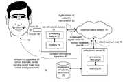
- FIG. 1illustrates an orthodontic system 10 that includes a site orthodontic system 12 and an orthodontic server 14 that are operably coupled together via a communication network 16 .
- the site orthodontic system 12includes a scanner (not shown) to scan the mouth and facial features of a patient 18 .
- the site orthodontic system 12also includes a processing module 20 and memory 22 .
- the processing module 20may be a single processing device or a plurality of processing devices. Such a processing device may be a microprocessor, microcomputer, digital signal processor, central processing unit of a computer or work station, digital circuitry, state machine, and/or any device that manipulates signals (e.g., analog and/or digital) based on operational instructions.
- the memory 22may be a single memory device or a plurality of memory devices. Such a memory device may be a random access memory, read-only memory, floppy disk memory, hard drive memory, extended memory, magnetic tape memory, zip drive memory and/or any device that stores digital information. Note that when the processing module 20 implements one or more of its functions, via a state machine or logic circuitry, the memory storing the corresponding operational instructions is embedded within the circuitry comprising the state machine or logic circuitry.
- the orthodontic server 14includes a processing module 24 and memory 26 .
- the processing module 24may be a single processing device or a plurality of processing devices. Such a processing device may be a microprocessor, microcontroller, digital signal processor, microcomputer, central processing unit of a personal computer or a work station, logic circuitry, state machine and/or any other device that manipulates signals (analog and/or digital) based on operational instructions.
- the memory 26may be a single memory device or a plurality of memory devices. Such a memory device may be read-only memory, random access memory, floppy disk memory, magnetic tape memory, hard drive memory, magnetic tape memory, and/or any device that stores digital information. Note that when the processing module 24 implements one or more of its functions, via a state machine or logic circuitry, the memory storing the corresponding operational instructions is imbedded within the circuitry comprising the state machine or logic circuitry.
- the orthodontic server 14is operably coupled to a database 28 of orthodontic parameters.
- the orthodontic parametersinclude, but are not limited to, age, gender, race, physical geometry of a patient's teeth, mouth structure, bone structure, type of malocclusion, ethnicity, function, etc.
- the orthodontic parametersinclude any human characteristic related to orthodontics that affects tooth positioning, movement, function, stability, appearance, structure of the bones, teeth, gums, pathology, patient's knowledge, medical history, dental history, etc. and mechanical characteristics of the orthodontic apparatus that may be stored in a database system to enhance prediction of a patient's orthodontic treatment.
- the orthodontic parametersinclude case histories of previously treated patients that are used to determine normal expected treatments, mechanical aspects of the brackets, bands, and wire, mean deviation from normalized treatments, and other statistical information regarding the normalized treatment of an orthodontic patient.
- this informationis added to the database 28 .
- the communication network 16 coupling the site orthodontic system 12 to the orthodontic server 14may be a local area network, wide area network, the Internet, the public switching telephone network (PSTN), a direct connect wire, ATM network, and/or any other type of data transport structure.
- the orthodontic system 10may be a self-contained system when the communication network 16 is a direct connect wire. Such a self-contained system would reside at an orthodontist's office or treatment center (e.g., a center run by practitioners).
- the orthodontic system 10may include a plurality of site orthodontic systems 12 located in the same building, or office, such that an orthodontist, or group of orthodontists, may have multiple treatment rooms for simultaneous patient treatment.
- the orthodontic system 10may include a plurality of site orthodontic systems 12 that are located in different geographic locations (e.g., different buildings, different offices, different towns, different states, or different countries) than the orthodontic server 14 .
- the communication network 16would be a wide area network, local area network, the Internet, and/or the PSTN.
- a distributed systemmay include a plurality of orthodontic servers 14 .
- the overall processing of a patient's orthodontic treatmentis essentially the same.
- the patient's orthodontic structureis scanned 30 .
- the patient's orthodontic structureincludes the patient's teeth, facial tissue, gums, bone structure, and any other physical feature that affects the patient's orthodontic treatment or is influenced by orthodontic care.
- the scanned image of the patient's orthodontic structureis provided to the site orthodontic system 12 . Note that a specific embodiment of scanning is described in U.S.
- a model, impression, or a stereolithograph (SLA) modelmay be scanned at the orthodontic site or the site of the server.
- the patient informationmay be referenced by a code to provide anonymity to the identity of the patient.
- the site orthodontic system 12converts the scanned image of the patient's orthodontic structure into a digital model of the patient's malocclusions 32 . Such a conversion is done by receiving the scanned image of the patient's orthodontic structure, x-rays of the patient's orthodontic structure, photographs, and/or other patient information and generating the three-dimensional (3-D) digital model therefrom. Such a conversion process is described in co-pending patent application having a title of “Method and Apparatus for Producing a Three-Dimensional Digital Model of an Orthodontic Patient”, Ser. No. 09/560,641 filed Apr. 28, 2000 which is hereby incorporated herein by reference. Alternatively, the site orthodontic system 12 may pass the scanned data, the x-rays, and the other patient information to the orthodontic server 14 and the orthodontic server 14 generates the 3-D digital model.
- the site orthodontic system 12then transports the digital model of the patient's malocclusions 32 and an electronic patient record via the communication network 16 to the orthodontic server 14 .
- the electronic patient recordis a compilation of patient specific information that is beneficial in treating the patient and includes, but is not limited to, clinical examination interpretations, radiology examination measurements, automatic and manual cephalometric analysis, a created electronic cephalometric tracings, an electronic composite including an integration of the three-dimensional images, radiographic data (e.g., x-rays, CAT scans, MRI scans), photographs, a generated electronic articulation module, measurements and analysis of electronic models, data quality assurance checks, patient's demographic data, patient's chief complaint, disclaimer forms, insurance, medical history, dental history, patient's progress notes, patient's billing schedule and tracking, patient educational information, and/or supplemental data.
- radiographic datae.g., x-rays, CAT scans, MRI scans
- photographse.g., a generated electronic articulation module
- orthodontic parameters of like casesare retrieved from the database 28 , which is used by the orthodontic server 14 to generate an initial treatment plan 34 .
- the orthodontic treatment planincludes a plurality of precise steps applied in sequence to obtain a desired orthodontic structure.
- Generation of the initial treatment planis described in co-pending patent applicant entitled “Method and Apparatus for Automated Generation of a Patient Treatment Plan”, Ser. No. 09/560,647 filed Apr. 28, 2000, which is hereby incorporated herein by reference.
- the orthodontic server 14provides the initial treatment plan to the site orthodontic system 12 via the communication network 16 . If the site orthodontic system 12 confirms the initial treatment plan 34 (e.g., the orthodontist provides inputs to the system 12 that the patient and orthodontist agree to the treatment plan), the orthodontic server 14 designs an orthodontic apparatus 36 .
- the designing of the orthodontic apparatusis described in co-pending patent application entitled “Method and Apparatus for Designing an Orthodontic Apparatus to Provide Tooth Movement”, Ser. No. 09/560,128 filed Apr. 28, 2000, which is hereby incorporated herein by reference.
- the orthodontic apparatus 36includes at least a wire, and/or a wire and brackets, and may further include one or more of bands, bonding agent thickness, headgear, rubber bands, bracket placement provide information, a retaining device, functional appliances (e.g., Herbst appliance, expander, etc.) and other mechanical devices to provide tooth movement (active apparatus) and/or tooth anchoring (passive apparatus).
- the orthodontic apparatus 36is then fabricated/assembled and provided to the orthodontists for installation on the patient 18 .
- the patient's orthodontic structureis rescanned 38 .
- the rescanned orthodontic structureis converted into a digital model of the patient's current stage of malocclusion 32 by the site orthodontic system 12 .
- the site orthodontic system 12then provides the revised, or a new, digital model of the patient's current stage of malocclusion 32 to the orthodontic server 14 .
- the orthodontic server 14determines whether the actual orthodontic structure of the patient corresponds to the calculated or estimated orthodontic structure per the corresponding step of the initial treatment plan.
- the estimated orthodontic structureis determined based on the initial treatment plan and the corresponding design of the apparatus structure.
- the orthodontic server 14causes the next orthodontic apparatus 36 to be generated in accordance with the next step of the initial treatment plan.
- a substantial matchoccurs when the three-dimensional position of the teeth in the actual orthodontic structure are less than one millimeter different in any one of the X, Y and Z direction than the estimated placement (i.e., the calculated position for the corresponding step of the initial treatment plan), when the function of the upper and lower arches are substantially as predicted, stability of the teeth is substantially as desired, and/or the appearance is substantially as desired for the given step.
- the orthodontic structuremay be scanned immediately after placement of the brackets to verify correct bracket placement, such verification will be discussed in greater detail with reference to FIG. 13 .
- the orthodontic server 14determines that the actual orthodontic structure does not match the estimated orthodontic structure, the orthodontic server 14 adjusts the treatment plan based on the actual orthodontic structure, related orthodontic parameters used to create the initial treatment plan, inputs from a practitioner, any other orthodontic parameters to accommodate the revised treatment plan, and the desired orthodontic structure. Based on the revised treatment plan, the orthodontic server 14 designs the next orthodontic apparatus 36 to be applied.
- the newly designed orthodontic apparatus 36is provided to the orthodontist for installation on the patient. This process continues for each installation of the orthodontic apparatus 36 on the patient's mouth until the treatment plan has been completed.
- the orthodontic apparatus 36will include, for the initial orthodontic apparatus installation, bracket and a wire having bends to provide a three-dimensional displacement or stabilization of at least one tooth.
- the orthodontic apparatusincludes a wire and may further include rubber band placement, head-gear, etc.
- a closed loop systemis provided to treat an orthodontic condition of a patient in a scientific manner throughout the treatment.
- wiresto provide the three-dimensional displacement of teeth
- corrections throughout the treatment planmay readily be made to achieve the desired orthodontic structure.
- customized wiresprovide more rapid treatment due to optimal forces being applied to each tooth.
- the orthodontic apparatuswill be fabricated to provide the appropriate tooth displacement in accordance with the treatment plan.
- a wiremay provide one-dimensional tooth displacement, two-dimensional tooth displacement, three-dimensional tooth displacement or tooth stabilization in any one of the three planes of space.
- Alternative uses of the orthodontic system 10include, but are not limited to, a one time use that generates all the wires needed for treatment, use to assist in bracket placement, generate a single super elastic wire and one finishing wire, and/or a one time use for comparative diagnostic.
- the orthodontic system 10may be used in a variety of ways to make the practice of orthodontic more of a science than an art.
- various levels of securitymay be used within the system 10 , allowing certain users access to all information while restricting access of others to a portion of the information.
- FIG. 2illustrates a schematic block diagram of an alternate orthodontic system 50 .
- the orthodontic system 50includes at least two sites, an orthodontist's office, or orthodontic treatment facility, 52 and a manufacturing center 54 (e.g., a laboratory).
- the system 50may also include a remote site 56 .
- the portion of the system 50 located at the orthodontists office 52includes site orthodontic system 12 , a display 62 , and a scanning device 58 .
- the orthodontic' office 52may also include other site computers 76 that integrate the orthodontist's office computers into a single system. As such billings, records, inventory, etc. may be networked together within the site orthodontic system 50 to provide a single system at the orthodontist's office 52 .
- the system 50may be networked with product manufacturers of the orthodontic apparatus materials.
- the scanning device 58provides a white light signal, laser, ultra sound, and/or infrared on to the patient's teeth 70 to obtain a scanned image. Such scanning is done under the control of the site orthodontic system 60 via control signals.
- the scanning device 58retrieves a static or dynamic image of the patient's teeth, which is provided to the site orthodontic system 12 .
- the site orthodontic system 12includes an electronic patient section 64 , an image processing section 66 , a controller section 68 , and a user interface section (not shown). Note that each of these separate sections may be achieved via operational instructions stored in memory 22 and executed by the processing module 20 .
- the electronic patient section 64contains the three-dimensional scanned images of the patient, x-rays, clinical exams and measurements, dental history, medical history, patient consent forms, photographs, template entries such as chief complaints, etc., free form entries, and extra data.
- the image processing module 66receives the data of the patient's teeth and produces therefrom the three-dimensional image.
- the digital informationis provided to the orthodontic server 14 via the communication network 16 .
- controller 68provides control signals to the scanning device 58 which cause the scanning device 58 to obtain the video information, or scanned image, of the patient's teeth 70 .
- video informationincludes, but is not limited to, live video images, still video images, and/or photographs.
- the orthodontic server 14upon receiving the information from the site orthodontic system 12 generates an electronic patient record for this particular patient.
- the electronic patient recordincludes, but is not limited to, clinical examination and interpretations, radiological examination measurements, automatic and manual cephalometric analysis, created electronic cephalometric tracings, an electronic composite of the 3-D images, radio graphic data, and photographs, generated electronic articulation models, measured and analyzed electronic modules, data quality assurance checks and/or supplemental data.
- the orthodontic server 14includes a simulator module 84 , a web server 86 , and a diagnostic support module 88 .
- the simulator module 84utilizes the electronic patient record and orthodontic parameters from the database 28 to design the orthodontic apparatus.
- the design of the wireis then provided to the wire bending robot 82 , which bends the wire of the orthodontic apparatus in three-dimensions such that the wire provides three-dimensional displacement of the patient's teeth. If the orthodontic apparatus includes auxiliary appliances, the design for such appliances is provided to a manufacturer for fabrication.
- the wireprovide the three-dimensional displacements, the brackets applied to the patient's teeth may be generic.
- the wire bending robot 82may be a bending robot as manufactured by OraMetrix, Inc.
- the web server 86provides a web page for patients to obtain patient information 92 and for practitioners to access practitioner information 94 .
- the orthodontic server 14may provide patients with a web page for answers to frequently asked questions, chat groups, tips on maintaining proper dental care during orthodontic treatment and/or any information related to a patient's dental and/or orthodontic care needs.
- the orthodontic server 14may also provide practitioner information 94 to practitioners.
- Such information 94may be located on a web page that provides practitioners with information related to the practice of orthodontic.
- the web pagemay provide information related to the particular patient being treated. Such information may be accessed utilizing a password or some form of encryption key.
- the orthodontic server 14includes a diagnostic support module 88 that actually generates the corresponding information that is provided to the simulator 84 .
- the diagnostic support module 88may be coupled to a diagnostic computer 90 and support facility equipment 91 .
- the diagnostic computer 90may be operated by an orthodontist or professional associated with the manufacturing center 54 to coordinate the design and maintenance of the orthodontic apparatus.
- the diagnostic computerprovides an input for practitioners to provide the clinical examination information and other patient related data.
- the support facility 91may include a personal computer, or work station, that tracks patient billing information, and/or supplemental patient information relating to the orthodontic treatment.
- the system 50may also include a remote diagnostic computer 78 located at the remote site 56 .
- the remote diagnostic computer 78allows orthodontists and/or other practitioners not located at the manufacturing center 54 to provide input as to the orthodontic treatment of a particular patient.
- the remote diagnostic computer 78may be operated by a specialist who has been consulted for a particular case.
- the initial treatment plan generated by the orthodontic server 14may include inputs from multi-faceted disciplines. For example, before the orthodontic treatment can begin a physician may need to be consulted for particular medical reasons. For instance, a patient may require particular medications before each treatment to avoid complications of certain medical conditions. In addition, before orthodontic treatment can begin, tooth extraction may be required, thus consultation with a dentist is needed. Further, a patient may require special treatment such as jaw surgery, headgear, rubber bands, etc. If special treatment is needed, the database 28 is accessed to determine whether there is a case match. If so, the case history for the previous treatment is integrated into the treatment plan for the present patient. If a case match was not found, the orthodontic practitioner's at the manufacturing site 54 using their expertise, the expertise of the care provider, consultants, etc., and/or near match case histories, to generate the initial treatment plan.
- the wire-bending robot 82generates the wires having three-dimensional bends to provide three-dimensional displacement of the patient's teeth. Based on inputs of the orthodontic server, the wire-bending robot generates the corresponding wires for each step of the treatment plan. Note that a full series of wires may be generated at one time, or the wires can be generated one at a time in accordance with a corresponding step of the treatment plan.
- precise bends, loops, and/or other force system manipulations in the wiresmay be obtained thereby eliminating the inaccuracies of human wire bending.
- three-dimensional bendsmay be achieved to provide three-dimensional displacement, or stabilization, of one or more teeth.
- the displacement of teethis primarily incorporated into the wires such that generic brackets may be used on the patient's teeth thereby reducing the costs.
- subsequent wires in the treatment planmay be manipulated to give updated tooth displacement such that the desired orthodontic structure is obtained within the prescribed treatment time.
- FIG. 3illustrates a graphical representation of a patient's teeth having an orthodontic apparatus attached thereto.
- the orthodontic apparatusincludes a plurality of brackets 102 and a wire 104 . As shown, the brackets 102 and wire 104 are installed below the gum and bone line 100 . Throughout the treatment, the brackets are fixed to the teeth whereby the wire 104 is manipulated to achieve the desired orthodontic structure (i.e., the desired tooth placement).
- the brackets 102may be the type of brackets found in FIG. 4 or FIG. 5 .
- FIG. 4illustrates a standard bracket or a generic prescription bracket 102 that includes a generic wire retention receptacle 106 .
- the generic wire retention receptacle 106is a simple groove (i.e., a slot) in the bracket 104 without complex angles or depths.
- the generic wire retention receptacle 106is a groove in the bracket 104 that includes a generic angularity. The wire 104 is inserted into the bracket as shown to provide the desired torque on the corresponding tooth.
- FIG. 5illustrates a custom bracket 102 having a specific wire retention receptacle 108 .
- the brackethas the retention receptacle 108 designed to include complex angles of depth and groove that are determined for a particular patient.
- the orthodontic apparatus applied to a patient's teethmay include brackets having generic wires retention receptacles 106 or brackets having specific wire retention receptacles 108 .
- FIG. 6illustrates a graphical representation of the actual placement of brackets and wire on the patient's teeth.
- the actual bracket placement 102is shown by the solid lines while the ideal bracket placement 112 is shown by the dashed lines.
- the adjusted wire design 110is shown in solid lines while the ideal wire design 116 is shown in dashed lines.
- the initial treatment planmay be created from the digital model of the patient's teeth prior to the installation of the brackets. The treatment plan may then be revised once the brackets are installed. As such, in the example shown in FIG.
- the treatment planmay be adjusted thereby yielding the adjusted wire design 110 .
- the treatmentwill still be ideal by redesigning the subsequent wires and/or a template, and/or instructions, on adjusting a present wire, to provide the desired displacement.
- the relative bracket positionchanges thereby causing the force system on the tooth to be different.
- each tooth surfaceis different, which, when a bracket is applied in accordance with a generic placement prescription, will generate a different force system causing varying tooth movement.
- the present inventionallows for such conditions and compensates for such conditions utilizing the closed loop feedback system previously discussed.
- FIG. 7illustrates a tooth 122 having a bracket 102 bonded thereto.
- the bracketis bonded using a bonding agent 120 , which has a thickness 124 .
- the force system on the toothmay vary.
- the present inventioncan incorporate the bonding agent thickness 124 into the treatment plan and compensate for variations thereof.
- the present inventionmay prescribe a particular bonding agent thickness 124 of varying angles and depths to achieve the desired tooth displacement.
- the base of the bracketmay be angular in two or three-dimensions of space to provide further displacement options.
- FIGS. 8 and 9illustrate the three-dimensional displacement achieved by the wires fabricated in accordance with the present invention.
- the treatment planindicates that one tooth is to have a Z direction movement 126 while a second tooth has a desired X, Z plane movement 128 .
- the wire 104is fabricated to provide the desired X, Z plane movement 128 and the desired Z direction movement 126 .
- the wireis fabricated to provide the desired X direction movement 132 of the first tooth and a desired Y direction movement 130 of the second tooth. As such, by fabricating the wire in accordance to the present invention, three-dimensional placement of the teeth 70 may be obtained.
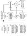
- FIG. 10illustrates a logic diagram of a method performed by the orthodontic server 14 to assist in the treatment of an orthodontic patient.
- the processbegins at step 140 where a digital model of a patient's malocclusion is generated from a three-dimensional image of the patient's orthodontic structure and/or facial structure.
- the three-dimensional imagemay be generated by scanning the patient's mouth and facial area.
- the orthodontic structureincludes the patient's teeth, gums, jawbone, and associated soft tissue while the facial structure includes further facial bones and soft tissue.
- the processthen proceeds to step 142 where an initial treatment plan is derived for the patient from the digital model and orthodontic parameters relating to the patient.
- the initial treatment planincludes precise steps to obtain a desired orthodontic structure.
- each wireis designed to provide three-dimensional displacement of the patient's orthodontic structure, when three-dimensional displacement is needed.
- the bracketsmay be fabricated for each tooth wherein each bracket includes a generic wire retention receptacle, a specific bonding thickness, a specific bracket base, and/or a specific wire retention receptacle.
- a wireis fabricated to provide three-dimensional displacement of the patient's orthodontic structure in accordance with a particular precise step.
- a wireis fabricated to provide three-dimensional displacement for brackets including a generic wire retention receptacle.
- at least one of the bracketsmay be fabricated with a specific wire retention receptacle that assists in providing three-dimensional displacement of the patient's tooth in accordance with the particular precise step.
- the bracket bonding thickness, or basemay be determined to further provide three-dimensional displacement of the patient's orthodontic structure (i.e., the patient's tooth or teeth).
- band sizing and fittingmay be simulated as part of the orthodontic apparatus, which allows for electronic selection of an appropriate band size or fabrication.
- step 146After a wire has been applied, a subsequent digital model is generated to represent a current actual orthodontic structure.
- step 148a determination is made as to whether the actual orthodontic structure substantially matches an estimated orthodontic structure.
- step 150the process branches depending on whether the determination at step 148 was a match. If the actual orthodontic structure did not match the estimated orthodontic structure (i.e., the calculated desired movement of the teeth), the process proceeds to step 152 .
- the initial treatment planis adjusted for subsequent precise steps to obtain the desired orthodontic structure. As such, a three-dimensional configuration of a new corresponding orthodontic apparatus (e.g., the wire) for one of the subsequent precise steps is redefined.
- step 158the next wire is applied.
- an adjustment to the treatment planmay simply be extended time to achieve the desired placement for a current step without changing a wire.
- the next stepmay use the same wire, but add new bends to it.
- the database of orthodontic parametersis updated with the digital models of abnormal treatment results of the patient to further enhance subsequent treatment. The process then reverts to step 146 .
- step 150If, at step 150 a match occurred, the process proceeds to step 154 .
- step 154a determination is made as to whether the treatment is complete. If not, the process proceeds to step 158 following the corresponding path. If, however, the treatment is complete the process proceeds to step 156 where a retaining apparatus is generated from a digital model of the adjusted patient's malocclusions.
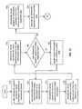
- FIG. 11illustrates a logic diagram of an alternate method for the orthodontic server to assist in the treatment of an orthodontic patient.
- the processbegins at step 140 where a digital model of a patient's malocclusion is generated from a three-dimensional image of the patient's orthodontic structure and facial structure. This may be achieved by scanning the patient's oral cavity to obtain the digital model using a three-dimensional light scanner.
- the processthen proceeds to step 142 where an initial treatment plan is determined for the patient from the digital model and orthodontic parameters relating to the patient.
- the initial treatment planincludes precise steps to obtain a desired orthodontic structure.
- the orthodontic parametersinclude, but are not limited to, age, gender, race, bone density, facial structure, tooth displacement, etc.
- the digital model of the patientmay be obtained subsequent to placement of the brackets on the patient's teeth. Having done this, the initial treatment plan may be adjusted to compensate for any manual misplacement of a bracket. Alternatively, the initial treatment plan may not be generated until after the initial placement of the brackets on the patient's teeth.
- a corresponding orthodontic apparatusis generated for a precise step of the initial treatment plan.
- the corresponding orthodontic apparatusmay include a wire, bracket, headgear, rubber bands, and/or a retainer.
- the orthodontic apparatusmay include a series of wires that correspond to the precise steps, a template for producing a wire for a given precise step, and/or an adjustment template for a wire of a subsequent precise step. If a template is developed, the orthodontist may make on-site accurate wire bend adjustments.
- step 162a subsequent digital model is generated after the orthodontic apparatus has been applied to obtain a digital image of the actual orthodontic structure. Note that a new digital model is obtained and recorded each time a precise step of the initial treatment plan is performed. Similarly, if the treatment plan is altered, digital models are obtained for the revised orthodontic structure.
- step 148a determination is made as to whether the actual orthodontic structure matches an estimated orthodontic structure.
- step 140routes further processing based on whether a match occurs. If a match does not occur, the process proceeds to step 142 where the initial treatment plan is adjusted for subsequent precise steps of the treatment plan to obtain the desired orthodontic structure.
- step 164the next orthodontic structure is applied to the patient's teeth. Having done this, the process repeats at step 162 .
- step 144a determination is made as to whether the treatment is complete. If not, the process proceeds to step 164 . If the treatment is complete, the process proceeds to step 146 .
- step 146a retaining apparatus is generated from a digital model of the adjusted patient's malocclusion.
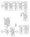
- FIGS. 12 through 14illustrate a logic diagram performed by the orthodontic system 10 and 50 .
- the processbegins at step 170 where a site orthodontic system generates digital information regarding an orthodontic patient.
- the digital informationincludes, but is not limited to, a three-dimensional image of the orthodontic patient's orthodontic structure, a two-dimensional image of the orthodontic' patient's orthodontic structure (e.g., x-rays and pictures) and patient data. Note that the three-dimensional image may be obtained by scanning the patient's mouth to obtain video data thereof and converting the video data into a three-dimensional image.
- the processthen proceeds to step 172 where the orthodontic site transmits the digital information to an orthodontic server.
- the digital informationmay be transmitted via an Internet connection, a local area network connection, a wide-area network connection, a direct connection, a direct connection, and/or a modem connection.
- the processthen proceeds to step 174 where the orthodontic server creates an electronic patient record from the digital information and is updated as further information is obtained.
- the electronic patient recordincludes, but is not limited to, clinical examination interpretations, radiology examination and measurements, automatic and/or manual cephalometric analysis, orthodontic history, mechanics plan, treatment objective, credit history, chronological data, task delegation, risk analysis, ordering information for orthodontic apparatus, electronic cephalometric tracings, integrated three-dimensional images and radiology and photograph images into an electronic composite, electronic articulation models, measurements and analysis of the electronic models, data quality assurance checks, and/or supplemental data.
- step 176the orthodontic server generates an initial treatment plan for the electronic patient.
- the orthodontic serverdetermines whether a multi-disciplinary treatment is involved. In other words, does the patient require additional medical treatment beyond orthodontic care. If so, a physician is consulted to obtain additional medical treatment information.
- the orthodontic serveralso determines whether interdisciplinary treatment is needed. As such, the orthodontic server determines whether other dental work is required beyond orthodontic treatment. For example, does the patient require tooth extraction. If so, the interdisciplinary treatment is added to the initial treatment plan. In addition, special treatment may be further required such as unique brackets, wiring, etc. If special treatment is required, orthodontic parameters are retrieved from a database wherein the orthodontic parameters are identified by cross matching at least some of the characteristics of the electronic patient record with orthodontic parameters of other electronic patient records. A first pass treatment plan is then generated based on the orthodontic parameters in the electronic patient record. The special treatment information is then integrated with the first pass treatment plan to produce the initial treatment plan. If special treatment is not required, the first pass plan is used as the initial treatment plan.
- step 178the orthodontic server transmits the initial treatment plan to the site orthodontic system.
- step 180a determination is made as to whether the site orthodontic system approved of the initial plan via inputs from a practitioner. If not, the process proceeds to step 182 where digital information regarding the patient is updated with additional patient data. The process then reverts to step 172 .
- step 184the orthodontic server designs an orthodontic apparatus for a first precise step of the initial treatment plan.
- the initial designmay be enhanced by the use of a remote diagnostic computer such that additional experts may be consulted to generate the treatment and/or orthodontic apparatus.
- the processthen proceeds to step 186 where the orthodontic apparatus is fabricated for the first precise step.
- the orthodontic apparatusincludes brackets, an active wire, a passive wire, specialty appliances and indirect bonding tray.
- the orthodontic apparatusincludes brackets, a first active wire, a passive wire, and specialty appliances.
- the active wireincludes the three-dimensional bends that apply the three-dimensional displacement of the tooth and a passive wire provides zero forces upon a given tooth. Further note that the wire may include an active portion and a passive portion.
- step 188the site orthodontic system updates the digital information after placement of the brackets.
- step 90the site orthodontic system provides the updated digital information to the orthodontic server.
- step 192a determination is made as to whether placement of the brackets is within a given tolerance. If not, the process proceeds to step 194 where at least one bracket is repositioned. Having repositioned the brackets, the process reverts to step 188 . Note that the determination of whether the brackets are within a given tolerance may be done in real time such that the repositioning of the brackets has minimal impact on the patient's care and/or time of treatment.
- step 196a wire is fabricated to provide three-dimensional displacement using the actual placement of the brackets in accordance with the first precise step.
- the orthodontic apparatusincludes brackets, a wire, bands, auxiliary appliances, headgear, rubber band placement and/or a retaining structure.
- step 198the wire is installed into the patient's mouth.
- step 200the site orthodontic system scans the patient's mouth to obtain an actual orthodontic structure.
- step 202the site orthodontic system transmits the new digital information containing the actual orthodontic structure to the orthodontic server.
- step 204the orthodontic server determines whether the actual orthodontic structure matches an estimated orthodontic structure corresponding to the precise step.
- step 206a branch occurs depending on whether a match occurs within step 204 . If a match does not occur, the process proceeds to step 208 where the treatment plan is adjusted for subsequent precise steps. As such, the treatment plan is revised to correct for the non-compliant tooth movement.
- step 210the treatment of the patient proceeds to the next precise step in accordance with the adjusted treatment plan. Having done this, the process reverts to step 196 . Note that, even if a matched occurred at step 206 , the practitioner may choose to make an adjustment to expedite treatment. As such, step 208 would be used to achieve the expedited treatment.
- step 212a determination is made as to whether the treatment is complete. If so, the process proceeds to step 216 where the orthodontic server designs a retaining device using the electronic patient record which has been updated throughout the treatment. Note that the orthodontic server may design the retaining device at or near the completion of treatment. If the treatment is not complete, the process proceeds to step 214 where the treatment of the patient proceeds to the next step in accordance with the initial treatment plan. Upon proceeding to the next step, the process reverts to step 196 of FIG. 13 .
- FIG. 15illustrates a logic diagram of a method for the site orthodontic system to support the treatment of an orthodontic patient.
- the processbegins at step 220 where digital information regarding an orthodontic patient is generated.
- the digital informationincludes a three-dimensional image of the patient's orthodontic structure, a two-dimensional image of the orthodontic patient's orthodontic structure and patient data.
- the processthen proceeds to step 222 where the digital information is transmitted to an orthodontic server.
- the processthen proceeds to step 224 where a digital version of the treatment plan is received.
- the site orthodontic systemmay transmit a confirmation acknowledgment to the orthodontic server.
- step 226the digital information is updated after the placement of the brackets. If a bracket were misplaced, the bracket would be repositioned and the digital information would be updated.
- step 228the updated digital information is transmitted to the orthodontic server.
- step 230digital information is generated for each application of an orthodontic structure in accordance with one of the precise steps. As the digital information is generated, it is transmitted to the orthodontic server. This continues until the treatment is complete.
- updates of the patient treatmentmay be provided to the patient, via a soft copy using email or a hard copy, to a care provider, and/or to any other practitioner associated with the treatment of the patient. Such updates may correspond to the precise steps of the treatment plan, scheduled visits of the patient, and/or any other desired triggering event.
- FIG. 16illustrates a logic diagram of an alternate method for the site orthodontic system to assist in the treatment of an orthodontic patient.
- the processbegins at step 240 where the patient's mouth is scanned to obtain video data of the orthodontic patient structure.
- the processthen proceeds to step 242 where the video data is converted into a three-dimensional image.
- the processthen proceeds to step 244 where the digital information is transmitted to an orthodontic server where the digital information includes a three-dimensional image.
- the processthen proceeds to step 246 where a digital version of the initial treatment is received.
- any factor that effects tooth movementi.e. brackets, wires, adhesion, physiological changes
- any factor that effects tooth movementcan be simulated to determine appropriate treatment changes.
- Such compensation in treatmentis not possible using prior methods which were based upon assumptions from a single model that the tooth movement would progress in a known manner. Therefore, the prior art methods would specify and a single static treatment based upon this assumption. If any unwanted tooth movement occurred during treatment, the specified treatment would no longer be valid, requiring changes to be made based upon a practitioner's expertise.
- the present systemprovides a dynamic system that through the use of periodic feedback, i.e. periodic three-dimensional scanning, can be monitored and adjusted as needed by the system in an efficient manner.
- periodic feedbacki.e. periodic three-dimensional scanning
- unexpected tooth movementsuch as occurs when a patient does not cooperate, or through biological changes, can be readily controlled.
- each step of the treatmentmay be monitored and correspondingly adjusted, if needed, thereby providing a more cost efficient and effective orthodontic treatment.
- wires to provide three-dimensional displacement of a toothexpensive custom brackets are not required thereby further reducing the cost of, and improving the accuracy of, orthodontic treatment.
- the systemmay be used in an open loop manner to provide one-time diagnostic information, bracket placement verification, and/or generation of the orthodontic apparatus without monitoring.
- other embodimentsmay be derived from the teaching of the present invention without deviating from the scope of the claims.
Landscapes
- Health & Medical Sciences (AREA)
- Oral & Maxillofacial Surgery (AREA)
- Dentistry (AREA)
- Epidemiology (AREA)
- Life Sciences & Earth Sciences (AREA)
- Animal Behavior & Ethology (AREA)
- General Health & Medical Sciences (AREA)
- Public Health (AREA)
- Veterinary Medicine (AREA)
- Dental Tools And Instruments Or Auxiliary Dental Instruments (AREA)
Abstract
Description
Claims (20)
Priority Applications (14)
| Application Number | Priority Date | Filing Date | Title |
|---|---|---|---|
| US09/560,642US6688885B1 (en) | 1999-11-30 | 2000-04-28 | Method and apparatus for treating an orthodontic patient |
| PCT/US2001/011969WO2001080761A2 (en) | 2000-04-19 | 2001-04-13 | Interactive orthodontic care system based on intra-oral scanning of teeth |
| EP10009822.7AEP2258303B1 (en) | 2000-04-19 | 2001-04-13 | System for creating an individual three-dimensional virtual tooth model |
| JP2001577864AJP2004504077A (en) | 2000-04-19 | 2001-04-13 | Interactive orthodontic care system based on intraoral scanning of teeth |
| US09/835,039US6648640B2 (en) | 1999-11-30 | 2001-04-13 | Interactive orthodontic care system based on intra-oral scanning of teeth |
| EP10004337.1AEP2204136B1 (en) | 2000-04-19 | 2001-04-13 | Orthodontic archwire |
| AT01928490TATE488313T1 (en) | 2000-04-19 | 2001-04-13 | BENDING MACHINE FOR A MEDICAL DEVICE |
| EP01928490.0AEP1301140B2 (en) | 2000-04-19 | 2001-04-13 | Bending machine for a medical device |
| US10/280,758US7029275B2 (en) | 1999-11-30 | 2002-10-24 | Interactive orthodontic care system based on intra-oral scanning of teeth |
| US10/951,119US7013191B2 (en) | 1999-11-30 | 2004-09-27 | Interactive orthodontic care system based on intra-oral scanning of teeth |
| US11/285,629US7590462B2 (en) | 1999-11-30 | 2005-11-22 | Interactive orthodontic care system based on intra-oral scanning of teeth |
| JP2007261981AJP5269380B2 (en) | 2000-04-19 | 2007-10-05 | Interactive orthodontic care system based on intraoral scanning of teeth |
| US12/510,921US8121718B2 (en) | 1999-11-30 | 2009-07-28 | Interactive orthodontic care system based on intra-oral scanning of teeth |
| JP2012090832AJP2012179370A (en) | 2000-04-19 | 2012-04-12 | Interactive orthodontic care system based on intra-oral scanning of teeth |
Applications Claiming Priority (2)
| Application Number | Priority Date | Filing Date | Title |
|---|---|---|---|
| US09/451,560US6540512B1 (en) | 1999-11-30 | 1999-11-30 | Method and apparatus for treating an orthodontic patient |
| US09/560,642US6688885B1 (en) | 1999-11-30 | 2000-04-28 | Method and apparatus for treating an orthodontic patient |
Related Parent Applications (2)
| Application Number | Title | Priority Date | Filing Date |
|---|---|---|---|
| US09/451,560Continuation-In-PartUS6540512B1 (en) | 1999-11-30 | 1999-11-30 | Method and apparatus for treating an orthodontic patient |
| US09/560,641Continuation-In-PartUS6512994B1 (en) | 1999-03-08 | 2000-04-28 | Method and apparatus for producing a three-dimensional digital model of an orthodontic patient |
Related Child Applications (4)
| Application Number | Title | Priority Date | Filing Date |
|---|---|---|---|
| US09/560,129Continuation-In-PartUS6318995B1 (en) | 1999-11-30 | 2000-04-28 | Method and apparatus for bonding a bracket to a tooth |
| US09/560,643Continuation-In-PartUS6464496B1 (en) | 1999-11-30 | 2000-04-28 | Method and apparatus for determining and monitoring orthodontic treatment |
| US09/835,039Continuation-In-PartUS6648640B2 (en) | 1999-11-30 | 2001-04-13 | Interactive orthodontic care system based on intra-oral scanning of teeth |
| US10/280,758Continuation-In-PartUS7029275B2 (en) | 1999-11-30 | 2002-10-24 | Interactive orthodontic care system based on intra-oral scanning of teeth |
Publications (1)
| Publication Number | Publication Date |
|---|---|
| US6688885B1true US6688885B1 (en) | 2004-02-10 |
Family
ID=43063398
Family Applications (1)
| Application Number | Title | Priority Date | Filing Date |
|---|---|---|---|
| US09/560,642Expired - LifetimeUS6688885B1 (en) | 1999-11-30 | 2000-04-28 | Method and apparatus for treating an orthodontic patient |
Country Status (1)
| Country | Link |
|---|---|
| US (1) | US6688885B1 (en) |
Cited By (52)
| Publication number | Priority date | Publication date | Assignee | Title |
|---|---|---|---|---|
| US20020180760A1 (en)* | 2001-04-13 | 2002-12-05 | Orametrix, Inc. | Method and workstation for generating virtual tooth models from three-dimensional tooth data |
| US20030225594A1 (en)* | 2002-05-28 | 2003-12-04 | Bergersen Earl O. | Dental appliances and systems and methods for distributing dental appliances |
| US20040086827A1 (en)* | 2002-01-16 | 2004-05-06 | Mcgann Benson D. | Archwire system |
| US20050244790A1 (en)* | 2004-04-30 | 2005-11-03 | Lester Kuperman | Method and apparatus for indirect bonding of orthodontic appliances to teeth |
| US20060147873A1 (en)* | 2002-04-22 | 2006-07-06 | Mcgann Benson D | Archwire system |
| US20070238064A1 (en)* | 2006-04-10 | 2007-10-11 | 3M Innovative Properties Company | Automatic adjustment of an orthodontic bracket to a desired mesio-distal position within a three-dimensional (3d) environment |
| US20080261165A1 (en)* | 2006-11-28 | 2008-10-23 | Bob Steingart | Systems for haptic design of dental restorations |
| US20090063192A1 (en)* | 2007-09-05 | 2009-03-05 | Group Technologies, Inc. | System and method of treating Tempro Mandibular Disorders utilizing a protocol of examinations, diagnostics, procedures and treatments to generate letters, reports and coded insurance claim forms to maximize benefit payments |
| US20090220920A1 (en)* | 2005-03-01 | 2009-09-03 | Primus Carolyn M | Methods for indirect bonding of orthodontic appliances |
| US20090317757A1 (en)* | 2008-06-24 | 2009-12-24 | Marc Lemchen | Method for Using Radio Frequency Identification Microchips in Orthodontic Brackets |
| US20100076581A1 (en)* | 2008-06-02 | 2010-03-25 | Violante Kimberly L | Methods for designing a customized dental prosthesis using digital images of a patient |
| US20100167225A1 (en)* | 2008-12-30 | 2010-07-01 | Align Technology, Inc. | Method and system for dental visualization |
| US20100291505A1 (en)* | 2009-01-23 | 2010-11-18 | Curt Rawley | Haptically Enabled Coterminous Production of Prosthetics and Patient Preparations in Medical and Dental Applications |
| US8013853B1 (en)* | 2002-03-06 | 2011-09-06 | Regents Of The University Of Minnesota | Virtual dental patient |
| US8359114B2 (en) | 2006-11-28 | 2013-01-22 | Dentsable, Inc. | Haptically enabled dental modeling system |
| US20140170583A1 (en)* | 2012-12-19 | 2014-06-19 | Align Technology, Inc. | Apparatus and method for optically scanning an object in registration with a reference pattern |
| US20140227655A1 (en)* | 2013-02-12 | 2014-08-14 | Ormco Corporation | Integration of model data, surface data, and volumetric data |
| US9402695B2 (en) | 2010-05-17 | 2016-08-02 | H32 | Individualized jig for orthodontic braces, assembly formed by that jig, a base and a bracket, and its design methods |
| US20170231721A1 (en)* | 2016-01-19 | 2017-08-17 | Hadi Akeel | Automated Placement of Dental Orthodontic Attachments |
| US20170265966A1 (en)* | 2016-03-16 | 2017-09-21 | Marc Lemchen | System and method for ordering and manufacturing customized orthodontic appliances and product |
| WO2018118200A1 (en)* | 2016-12-21 | 2018-06-28 | uLab Systems, Inc. | Orthodontic planning systems |
| US10335250B2 (en) | 2015-10-07 | 2019-07-02 | uLab Systems, Inc. | Three-dimensional printed dental appliances using lattices |
| US10335252B2 (en)* | 2007-02-26 | 2019-07-02 | Align Technology, Inc. | System and method for digital tooth imaging |
| US10357342B2 (en) | 2016-09-21 | 2019-07-23 | uLab Systems, Inc. | Digital dental examination and documentation |
| US10357336B2 (en) | 2015-10-07 | 2019-07-23 | uLab Systems, Inc. | Systems and methods for fabricating dental appliances or shells |
| US10548690B2 (en) | 2015-10-07 | 2020-02-04 | uLab Systems, Inc. | Orthodontic planning systems |
| US10617489B2 (en) | 2012-12-19 | 2020-04-14 | Align Technology, Inc. | Creating a digital dental model of a patient's teeth using interproximal information |
| US10624717B2 (en) | 2015-10-07 | 2020-04-21 | Ulab Systems Inc. | Tooth modeling system |
| US10631953B2 (en) | 2015-10-07 | 2020-04-28 | uLab Systems, Inc. | Three-dimensional printed dental appliances using support structures |
| US10828133B2 (en) | 2016-12-02 | 2020-11-10 | Swift Health Systems Inc. | Indirect orthodontic bonding systems and methods for bracket placement |
| US10881489B2 (en) | 2017-01-31 | 2021-01-05 | Swift Health Systems Inc. | Hybrid orthodontic archwires |
| US10952821B2 (en) | 2016-09-21 | 2021-03-23 | uLab Systems, Inc. | Combined orthodontic movement of teeth with temporomandibular joint therapy |
| CN112690913A (en)* | 2020-12-07 | 2021-04-23 | 上海牙典软件科技有限公司 | Tooth orthodontic plan generation method and system |
| US11058520B2 (en) | 2012-10-30 | 2021-07-13 | University Of Southern California | Orthodontic appliance with snap fitted, non-sliding archwire |
| US11058517B2 (en) | 2017-04-21 | 2021-07-13 | Swift Health Systems Inc. | Indirect bonding trays, non-sliding orthodontic appliances, and registration systems for use thereof |
| US11364098B2 (en) | 2016-09-21 | 2022-06-21 | uLab Systems, Inc. | Combined orthodontic movement of teeth with airway development therapy |
| US20220202530A1 (en)* | 2019-05-16 | 2022-06-30 | Alta Smiles Llc | Analysis and prediction model for orthodontic treatment |
| US11432907B2 (en) | 2012-09-06 | 2022-09-06 | Align Technology, Inc. | Method and a system usable in creating a subsequent dental appliance |
| US20220374119A1 (en)* | 2005-04-29 | 2022-11-24 | Align Technology, Inc. | Treatment of teeth by aligners |
| US11583365B2 (en) | 2015-10-07 | 2023-02-21 | uLab Systems, Inc. | System and methods for tooth movement as a flock |
| US11612458B1 (en) | 2017-03-31 | 2023-03-28 | Swift Health Systems Inc. | Method of tongue preconditioning in preparation for lingual orthodontic treatment |
| US11992383B2 (en) | 2021-06-23 | 2024-05-28 | uLab Systems, Inc. | System for force measurement upon orthodontic appliances |
| US12042354B2 (en) | 2019-03-01 | 2024-07-23 | Swift Health Systems Inc. | Indirect bonding trays with bite turbo and orthodontic auxiliary integration |
| US12053346B2 (en) | 2019-10-31 | 2024-08-06 | Swift Health Systems Inc. | Indirect orthodontic bonding systems and methods |
| US12053345B2 (en) | 2021-09-03 | 2024-08-06 | Swift Health Systems Inc. | Method of administering adhesive to bond orthodontic brackets |
| US12064315B2 (en) | 2019-04-30 | 2024-08-20 | uLab Systems, Inc. | Indirect bonding tray system |
| US12090025B2 (en) | 2020-06-11 | 2024-09-17 | Swift Health Systems Inc. | Orthodontic appliance with non-sliding archform |
| USD1043994S1 (en) | 2022-01-06 | 2024-09-24 | Swift Health Systems Inc. | Archwire |
| US12121411B2 (en) | 2020-08-19 | 2024-10-22 | uLab Systems, Inc. | Smile treatment planning systems and methods |
| US12150831B2 (en) | 2016-09-21 | 2024-11-26 | uLab Systems, Inc. | Combined orthodontic movement of teeth with cosmetic restoration |
| US12193908B2 (en) | 2021-09-03 | 2025-01-14 | Swift Health Systems, Inc. | Orthodontic appliance with non-sliding archform |
| US12268571B2 (en) | 2021-03-12 | 2025-04-08 | Swift Health Systems Inc. | Indirect orthodontic bonding systems and methods |
Citations (31)
| Publication number | Priority date | Publication date | Assignee | Title |
|---|---|---|---|---|
| US4575805A (en) | 1980-12-24 | 1986-03-11 | Moermann Werner H | Method and apparatus for the fabrication of custom-shaped implants |
| US5011405A (en) | 1989-01-24 | 1991-04-30 | Dolphin Imaging Systems | Method for determining orthodontic bracket placement |
| US5238404A (en) | 1992-04-27 | 1993-08-24 | Ormco Corporation | Orthodontic brace for positioning teeth |
| US5338198A (en) | 1993-11-22 | 1994-08-16 | Dacim Laboratory Inc. | Dental modeling simulator |
| US5368478A (en) | 1990-01-19 | 1994-11-29 | Ormco Corporation | Method for forming jigs for custom placement of orthodontic appliances on teeth |
| US5395238A (en) | 1990-01-19 | 1995-03-07 | Ormco Corporation | Method of forming orthodontic brace |
| DE4445552A1 (en) | 1993-12-22 | 1995-06-29 | Matsushita Electric Works Ltd | Optically-scanning displacement detector for contour measurement |
| US5431562A (en) | 1990-01-19 | 1995-07-11 | Ormco Corporation | Method and apparatus for designing and forming a custom orthodontic appliance and for the straightening of teeth therewith |
| US5447432A (en) | 1990-01-19 | 1995-09-05 | Ormco Corporation | Custom orthodontic archwire forming method and apparatus |
| US5454717A (en) | 1990-01-19 | 1995-10-03 | Ormco Corporation | Custom orthodontic brackets and bracket forming method and apparatus |
| US5456600A (en) | 1992-11-09 | 1995-10-10 | Ormco Corporation | Coordinated orthodontic archwires and method of making same |
| US5464349A (en) | 1993-11-09 | 1995-11-07 | Ormco Corporation | Orthodontic appliance providing for mesial rotation of molars |
| US5474448A (en) | 1990-01-19 | 1995-12-12 | Ormco Corporation | Low profile orthodontic appliance |
| US5518397A (en) | 1990-01-19 | 1996-05-21 | Ormco Corporation | Method of forming an orthodontic brace |
| US5533895A (en) | 1990-01-19 | 1996-07-09 | Ormco Corporation | Orthodontic appliance and group standardized brackets therefor and methods of making, assembling and using appliance to straighten teeth |
| US5542842A (en) | 1992-11-09 | 1996-08-06 | Ormco Corporation | Bracket placement jig assembly and method of placing orthodontic brackets on teeth therewith |
| US5618176A (en) | 1995-06-12 | 1997-04-08 | Ormco Corporation | Orthodontic bracket and ligature and method of ligating archwire to bracket |
| US5683243A (en)* | 1992-11-09 | 1997-11-04 | Ormco Corporation | Custom orthodontic appliance forming apparatus |
| DE19636354A1 (en) | 1996-09-02 | 1998-03-05 | Ruedger Dipl Ing Rubbert | Method and device for performing optical recordings |
| DE19638758A1 (en) | 1996-09-13 | 1998-03-19 | Rubbert Ruedger | Method and device for three-dimensional measurement of objects |
| DE19638727A1 (en) | 1996-09-12 | 1998-03-19 | Ruedger Dipl Ing Rubbert | Method for increasing the significance of the three-dimensional measurement of objects |
| US5772585A (en)* | 1996-08-30 | 1998-06-30 | Emc, Inc | System and method for managing patient medical records |
| US5879158A (en) | 1997-05-20 | 1999-03-09 | Doyle; Walter A. | Orthodontic bracketing system and method therefor |
| US5975893A (en) | 1997-06-20 | 1999-11-02 | Align Technology, Inc. | Method and system for incrementally moving teeth |
| US6068482A (en) | 1996-10-04 | 2000-05-30 | Snow; Michael Desmond | Method for creation and utilization of individualized 3-dimensional teeth models |
| US6099314A (en) | 1995-07-21 | 2000-08-08 | Cadent Ltd. | Method and system for acquiring three-dimensional teeth image |
| US6227850B1 (en) | 1999-05-13 | 2001-05-08 | Align Technology, Inc. | Teeth viewing system |
| US6227851B1 (en) | 1998-12-04 | 2001-05-08 | Align Technology, Inc. | Manipulable dental model system for fabrication of a dental appliance |
| US6315553B1 (en) | 1999-11-30 | 2001-11-13 | Orametrix, Inc. | Method and apparatus for site treatment of an orthodontic patient |
| US20020025503A1 (en) | 1999-12-29 | 2002-02-28 | Eric Chapoulaud | Custom orthodontic appliance forming method and apparatus |
| US6464496B1 (en)* | 1999-11-30 | 2002-10-15 | Orametrix, Inc. | Method and apparatus for determining and monitoring orthodontic treatment |
- 2000
- 2000-04-28USUS09/560,642patent/US6688885B1/ennot_activeExpired - Lifetime
Patent Citations (33)
| Publication number | Priority date | Publication date | Assignee | Title |
|---|---|---|---|---|
| US4575805A (en) | 1980-12-24 | 1986-03-11 | Moermann Werner H | Method and apparatus for the fabrication of custom-shaped implants |
| US5011405A (en) | 1989-01-24 | 1991-04-30 | Dolphin Imaging Systems | Method for determining orthodontic bracket placement |
| US5447432A (en) | 1990-01-19 | 1995-09-05 | Ormco Corporation | Custom orthodontic archwire forming method and apparatus |
| US5474448A (en) | 1990-01-19 | 1995-12-12 | Ormco Corporation | Low profile orthodontic appliance |
| US5368478A (en) | 1990-01-19 | 1994-11-29 | Ormco Corporation | Method for forming jigs for custom placement of orthodontic appliances on teeth |
| US5395238A (en) | 1990-01-19 | 1995-03-07 | Ormco Corporation | Method of forming orthodontic brace |
| US5533895A (en) | 1990-01-19 | 1996-07-09 | Ormco Corporation | Orthodontic appliance and group standardized brackets therefor and methods of making, assembling and using appliance to straighten teeth |
| US5431562A (en) | 1990-01-19 | 1995-07-11 | Ormco Corporation | Method and apparatus for designing and forming a custom orthodontic appliance and for the straightening of teeth therewith |
| US5518397A (en) | 1990-01-19 | 1996-05-21 | Ormco Corporation | Method of forming an orthodontic brace |
| US5454717A (en) | 1990-01-19 | 1995-10-03 | Ormco Corporation | Custom orthodontic brackets and bracket forming method and apparatus |
| US5238404A (en) | 1992-04-27 | 1993-08-24 | Ormco Corporation | Orthodontic brace for positioning teeth |
| US5456600A (en) | 1992-11-09 | 1995-10-10 | Ormco Corporation | Coordinated orthodontic archwires and method of making same |
| US5683243A (en)* | 1992-11-09 | 1997-11-04 | Ormco Corporation | Custom orthodontic appliance forming apparatus |
| US5542842A (en) | 1992-11-09 | 1996-08-06 | Ormco Corporation | Bracket placement jig assembly and method of placing orthodontic brackets on teeth therewith |
| US5464349A (en) | 1993-11-09 | 1995-11-07 | Ormco Corporation | Orthodontic appliance providing for mesial rotation of molars |
| US5338198A (en) | 1993-11-22 | 1994-08-16 | Dacim Laboratory Inc. | Dental modeling simulator |
| DE4445552A1 (en) | 1993-12-22 | 1995-06-29 | Matsushita Electric Works Ltd | Optically-scanning displacement detector for contour measurement |
| US5618176A (en) | 1995-06-12 | 1997-04-08 | Ormco Corporation | Orthodontic bracket and ligature and method of ligating archwire to bracket |
| US6099314A (en) | 1995-07-21 | 2000-08-08 | Cadent Ltd. | Method and system for acquiring three-dimensional teeth image |
| US5772585A (en)* | 1996-08-30 | 1998-06-30 | Emc, Inc | System and method for managing patient medical records |
| DE19636354A1 (en) | 1996-09-02 | 1998-03-05 | Ruedger Dipl Ing Rubbert | Method and device for performing optical recordings |
| DE19638727A1 (en) | 1996-09-12 | 1998-03-19 | Ruedger Dipl Ing Rubbert | Method for increasing the significance of the three-dimensional measurement of objects |
| DE19638758A1 (en) | 1996-09-13 | 1998-03-19 | Rubbert Ruedger | Method and device for three-dimensional measurement of objects |
| US6068482A (en) | 1996-10-04 | 2000-05-30 | Snow; Michael Desmond | Method for creation and utilization of individualized 3-dimensional teeth models |
| US5879158A (en) | 1997-05-20 | 1999-03-09 | Doyle; Walter A. | Orthodontic bracketing system and method therefor |
| US5975893A (en) | 1997-06-20 | 1999-11-02 | Align Technology, Inc. | Method and system for incrementally moving teeth |
| US6217325B1 (en) | 1997-06-20 | 2001-04-17 | Align Technology, Inc. | Method and system for incrementally moving teeth |
| US6227851B1 (en) | 1998-12-04 | 2001-05-08 | Align Technology, Inc. | Manipulable dental model system for fabrication of a dental appliance |
| US6227850B1 (en) | 1999-05-13 | 2001-05-08 | Align Technology, Inc. | Teeth viewing system |
| US6315553B1 (en) | 1999-11-30 | 2001-11-13 | Orametrix, Inc. | Method and apparatus for site treatment of an orthodontic patient |
| US6464496B1 (en)* | 1999-11-30 | 2002-10-15 | Orametrix, Inc. | Method and apparatus for determining and monitoring orthodontic treatment |
| US20020025503A1 (en) | 1999-12-29 | 2002-02-28 | Eric Chapoulaud | Custom orthodontic appliance forming method and apparatus |
| US20020028417A1 (en) | 1999-12-29 | 2002-03-07 | Eric Chapoulaud | Custom orthodontic appliance forming method and apparatus |
Non-Patent Citations (7)
| Title |
|---|
| Co-pending U.S. patent application of Rohit Sachdeva et al. Ser. No. 09/451,560 filed Nov. 30, 1999. |
| Co-pending U.S. patent application of Rohit Sachdeva et al., Ser. No. 09/560,646 filed Apr. 28, 2000. |
| S.M. Yamany and A.A. Farag, "A System for Human Jaw Modeling Using Intra-Oral Images" Proc. IEEE Eng. Med. Biol. Soc. (EMBS) Conf., vol. 20, Hong Kong, Oct. 1998, pp. 563-566. |
| S.M. Yamany, A.A. Farag, David Tasman, A.G. Farman, "A 3-D Reconstruction System for the Human Jaw Using a Sequence of Optical Images," IEEE Transactions on Medical Imaging, vol. 19, No. 5, May 2000, pp. 538-547. |
| Syrinx, 3D Scanner, Syrinx Technologies, Inc. Richardson TX (no date). |
| Syrinx, Bending Robot, Syrinx Technologies, Inc Richardson TX (no date). |
| Syrinx, Orthotherm, Syrinx Technologiesm Inc Richardson TX (no date). |
Cited By (97)
| Publication number | Priority date | Publication date | Assignee | Title |
|---|---|---|---|---|
| US20020180760A1 (en)* | 2001-04-13 | 2002-12-05 | Orametrix, Inc. | Method and workstation for generating virtual tooth models from three-dimensional tooth data |
| US7080979B2 (en)* | 2001-04-13 | 2006-07-25 | Orametrix, Inc. | Method and workstation for generating virtual tooth models from three-dimensional tooth data |
| US7008221B2 (en)* | 2002-01-16 | 2006-03-07 | Progressive America, Inc. | System for automatic selection of an archwire |
| US20040086827A1 (en)* | 2002-01-16 | 2004-05-06 | Mcgann Benson D. | Archwire system |
| US8013853B1 (en)* | 2002-03-06 | 2011-09-06 | Regents Of The University Of Minnesota | Virtual dental patient |
| US20060147873A1 (en)* | 2002-04-22 | 2006-07-06 | Mcgann Benson D | Archwire system |
| US20030225594A1 (en)* | 2002-05-28 | 2003-12-04 | Bergersen Earl O. | Dental appliances and systems and methods for distributing dental appliances |
| US7716062B2 (en)* | 2002-05-28 | 2010-05-11 | Ortho-Tain Inc | Dental appliances and systems and methods for distributing dental appliances |
| US20050244790A1 (en)* | 2004-04-30 | 2005-11-03 | Lester Kuperman | Method and apparatus for indirect bonding of orthodontic appliances to teeth |
| US8235717B2 (en) | 2004-04-30 | 2012-08-07 | Lester Kuperman | Method and apparatus for indirect bonding of orthodontic appliances to teeth |
| US8070486B2 (en) | 2004-04-30 | 2011-12-06 | Lester Kuperman | Method and apparatus for indirect bonding of orthodontic appliances to teeth |
| US20090220920A1 (en)* | 2005-03-01 | 2009-09-03 | Primus Carolyn M | Methods for indirect bonding of orthodontic appliances |
| US8308478B2 (en) | 2005-03-01 | 2012-11-13 | Dentsply International Inc. | Methods for indirect bonding of orthodontic appliances |
| US20220374119A1 (en)* | 2005-04-29 | 2022-11-24 | Align Technology, Inc. | Treatment of teeth by aligners |
| US20070238064A1 (en)* | 2006-04-10 | 2007-10-11 | 3M Innovative Properties Company | Automatic adjustment of an orthodontic bracket to a desired mesio-distal position within a three-dimensional (3d) environment |
| US7940258B2 (en)* | 2006-04-10 | 2011-05-10 | 3M Innovative Properties Company | Automatic adjustment of an orthodontic bracket to a desired mesio-distal position within a three-dimensional (3D) environment |
| US8359114B2 (en) | 2006-11-28 | 2013-01-22 | Dentsable, Inc. | Haptically enabled dental modeling system |
| US20080261165A1 (en)* | 2006-11-28 | 2008-10-23 | Bob Steingart | Systems for haptic design of dental restorations |
| US11007037B2 (en)* | 2007-02-26 | 2021-05-18 | Align Technology, Inc. | System and method for digital tooth imaging |
| US10405947B1 (en) | 2007-02-26 | 2019-09-10 | Align Technology, Inc. | System and method for digital tooth imaging |
| US10646307B2 (en) | 2007-02-26 | 2020-05-12 | Align Technology, Inc. | System and method for digital tooth imaging |
| US10335252B2 (en)* | 2007-02-26 | 2019-07-02 | Align Technology, Inc. | System and method for digital tooth imaging |
| US7885833B2 (en)* | 2007-09-05 | 2011-02-08 | Group Technologies, Inc. | System and method of treating Tempro Mandibular Disorders utilizing a protocol of examinations, diagnostics, procedures and treatments to generate letters, reports and coded insurance claim forms to maximize benefit payments |
| US20090063192A1 (en)* | 2007-09-05 | 2009-03-05 | Group Technologies, Inc. | System and method of treating Tempro Mandibular Disorders utilizing a protocol of examinations, diagnostics, procedures and treatments to generate letters, reports and coded insurance claim forms to maximize benefit payments |
| US20100076581A1 (en)* | 2008-06-02 | 2010-03-25 | Violante Kimberly L | Methods for designing a customized dental prosthesis using digital images of a patient |
| US8386061B2 (en) | 2008-06-02 | 2013-02-26 | Dentsply International Inc. | Methods for designing a customized dental prosthesis using digital images of a patient |
| US20090317757A1 (en)* | 2008-06-24 | 2009-12-24 | Marc Lemchen | Method for Using Radio Frequency Identification Microchips in Orthodontic Brackets |
| US8235716B2 (en)* | 2008-06-24 | 2012-08-07 | Marc Lemchen | Method for using radio frequency identification microchips in orthodontic brackets |
| US9642678B2 (en)* | 2008-12-30 | 2017-05-09 | Align Technology, Inc. | Method and system for dental visualization |
| US20100167225A1 (en)* | 2008-12-30 | 2010-07-01 | Align Technology, Inc. | Method and system for dental visualization |
| US11000350B2 (en) | 2008-12-30 | 2021-05-11 | Align Technology, Inc. | Method and system for dental visualization |
| US10512524B2 (en) | 2008-12-30 | 2019-12-24 | Align Technology, Inc. | Method and system for dental visualization |
| US20100291505A1 (en)* | 2009-01-23 | 2010-11-18 | Curt Rawley | Haptically Enabled Coterminous Production of Prosthetics and Patient Preparations in Medical and Dental Applications |
| US9402695B2 (en) | 2010-05-17 | 2016-08-02 | H32 | Individualized jig for orthodontic braces, assembly formed by that jig, a base and a bracket, and its design methods |
| US11432907B2 (en) | 2012-09-06 | 2022-09-06 | Align Technology, Inc. | Method and a system usable in creating a subsequent dental appliance |
| US12279925B2 (en) | 2012-10-30 | 2025-04-22 | University Of Southern California | Orthodontic appliance with snap fitted, non- sliding archwire |
| US11129696B2 (en) | 2012-10-30 | 2021-09-28 | University Of Southern California | Orthodontic appliance with snap fitted, non-sliding archwire |
| US11517405B2 (en) | 2012-10-30 | 2022-12-06 | University Of Southern California | Orthodontic appliance with snap fitted, non-sliding archwire |
| US11058520B2 (en) | 2012-10-30 | 2021-07-13 | University Of Southern California | Orthodontic appliance with snap fitted, non-sliding archwire |
| US11510757B2 (en) | 2012-10-30 | 2022-11-29 | University Of Southern California | Orthodontic appliance with snap fitted, non-sliding archwire |
| US11510758B2 (en) | 2012-10-30 | 2022-11-29 | University Of Southern California | Orthodontic appliance with snap fitted, non-sliding archwire |
| US11534266B2 (en) | 2012-12-19 | 2022-12-27 | Align Technology, Inc. | Creating a digital dental model of a patient's teeth using interproximal information |
| US20140170583A1 (en)* | 2012-12-19 | 2014-06-19 | Align Technology, Inc. | Apparatus and method for optically scanning an object in registration with a reference pattern |
| US10617489B2 (en) | 2012-12-19 | 2020-04-14 | Align Technology, Inc. | Creating a digital dental model of a patient's teeth using interproximal information |
| US10098714B2 (en)* | 2012-12-19 | 2018-10-16 | Align Technology, Inc. | Apparatus and method for optically scanning an object in registration with a reference pattern |
| US20140227655A1 (en)* | 2013-02-12 | 2014-08-14 | Ormco Corporation | Integration of model data, surface data, and volumetric data |
| US10631953B2 (en) | 2015-10-07 | 2020-04-28 | uLab Systems, Inc. | Three-dimensional printed dental appliances using support structures |
| US10548690B2 (en) | 2015-10-07 | 2020-02-04 | uLab Systems, Inc. | Orthodontic planning systems |
| US10881486B2 (en) | 2015-10-07 | 2021-01-05 | uLab Systems, Inc. | Three-dimensional printed dental appliances using lattices |
| US11833006B2 (en) | 2015-10-07 | 2023-12-05 | uLab Systems, Inc. | Systems and methods for fabricating dental appliances or shells |
| US11638628B2 (en) | 2015-10-07 | 2023-05-02 | Ulab Systems Inc. | Three-dimensional printed dental appliances using lattices |
| US11583365B2 (en) | 2015-10-07 | 2023-02-21 | uLab Systems, Inc. | System and methods for tooth movement as a flock |
| US10624717B2 (en) | 2015-10-07 | 2020-04-21 | Ulab Systems Inc. | Tooth modeling system |
| US11992381B2 (en) | 2015-10-07 | 2024-05-28 | uLab Systems, Inc. | Orthodontic planning systems |
| US11051913B2 (en) | 2015-10-07 | 2021-07-06 | Ulab Systems Inc. | Methods for fabricating dental appliances or shells |
| US11771524B2 (en) | 2015-10-07 | 2023-10-03 | uLab Systems, Inc. | Three-dimensional printed dental appliances using support structures |
| US11553989B2 (en) | 2015-10-07 | 2023-01-17 | uLab Systems, Inc. | Tooth modeling system |
| US10357336B2 (en) | 2015-10-07 | 2019-07-23 | uLab Systems, Inc. | Systems and methods for fabricating dental appliances or shells |
| US12279923B2 (en) | 2015-10-07 | 2025-04-22 | Ulab Systems Inc. | Systems and methods for fabricating dental appliances or shells |
| US10335250B2 (en) | 2015-10-07 | 2019-07-02 | uLab Systems, Inc. | Three-dimensional printed dental appliances using lattices |
| US20170231721A1 (en)* | 2016-01-19 | 2017-08-17 | Hadi Akeel | Automated Placement of Dental Orthodontic Attachments |
| US10299891B2 (en)* | 2016-03-16 | 2019-05-28 | Easyrx, Llc. | System and method for ordering and manufacturing customized orthodontic appliances and product |
| US20170265966A1 (en)* | 2016-03-16 | 2017-09-21 | Marc Lemchen | System and method for ordering and manufacturing customized orthodontic appliances and product |
| US10925698B2 (en) | 2016-09-21 | 2021-02-23 | uLab Systems, Inc. | Digital dental examination and documentation |
| US10588723B2 (en) | 2016-09-21 | 2020-03-17 | uLab Systems, Inc. | Digital dental examination and documentation |
| US10357342B2 (en) | 2016-09-21 | 2019-07-23 | uLab Systems, Inc. | Digital dental examination and documentation |
| US12193635B2 (en) | 2016-09-21 | 2025-01-14 | uLab Systems, Inc. | Digital dental examination and documentation |
| US11364098B2 (en) | 2016-09-21 | 2022-06-21 | uLab Systems, Inc. | Combined orthodontic movement of teeth with airway development therapy |
| US12150831B2 (en) | 2016-09-21 | 2024-11-26 | uLab Systems, Inc. | Combined orthodontic movement of teeth with cosmetic restoration |
| US11707180B2 (en) | 2016-09-21 | 2023-07-25 | uLab Systems, Inc. | Digital dental examination and documentation |
| US10952821B2 (en) | 2016-09-21 | 2021-03-23 | uLab Systems, Inc. | Combined orthodontic movement of teeth with temporomandibular joint therapy |
| US11911971B2 (en) | 2016-12-02 | 2024-02-27 | Swift Health Systems Inc. | Indirect orthodontic bonding systems and methods for bracket placement |
| US11612459B2 (en) | 2016-12-02 | 2023-03-28 | Swift Health Systems Inc. | Indirect orthodontic bonding systems and methods for bracket placement |
| US12207987B2 (en) | 2016-12-02 | 2025-01-28 | Swift Health Systems Inc. | Indirect orthodontic bonding systems and methods for bracket placement |
| US10828133B2 (en) | 2016-12-02 | 2020-11-10 | Swift Health Systems Inc. | Indirect orthodontic bonding systems and methods for bracket placement |
| AU2017382624B2 (en)* | 2016-12-21 | 2022-12-08 | uLab Systems, Inc. | Orthodontic planning systems |
| WO2018118200A1 (en)* | 2016-12-21 | 2018-06-28 | uLab Systems, Inc. | Orthodontic planning systems |
| US12370021B2 (en) | 2017-01-31 | 2025-07-29 | Swift Health Systems Inc. | Hybrid orthodontic archwires |
| US11957536B2 (en) | 2017-01-31 | 2024-04-16 | Swift Health Systems Inc. | Hybrid orthodontic archwires |
| US10881489B2 (en) | 2017-01-31 | 2021-01-05 | Swift Health Systems Inc. | Hybrid orthodontic archwires |
| US11612458B1 (en) | 2017-03-31 | 2023-03-28 | Swift Health Systems Inc. | Method of tongue preconditioning in preparation for lingual orthodontic treatment |
| US12220294B2 (en) | 2017-04-21 | 2025-02-11 | Swift Health Systems Inc. | Indirect bonding trays, non-sliding orthodontic appliances, and registration systems for use thereof |
| US11058517B2 (en) | 2017-04-21 | 2021-07-13 | Swift Health Systems Inc. | Indirect bonding trays, non-sliding orthodontic appliances, and registration systems for use thereof |
| US12042354B2 (en) | 2019-03-01 | 2024-07-23 | Swift Health Systems Inc. | Indirect bonding trays with bite turbo and orthodontic auxiliary integration |
| US12064315B2 (en) | 2019-04-30 | 2024-08-20 | uLab Systems, Inc. | Indirect bonding tray system |
| US20220202530A1 (en)* | 2019-05-16 | 2022-06-30 | Alta Smiles Llc | Analysis and prediction model for orthodontic treatment |
| US11819376B2 (en)* | 2019-05-16 | 2023-11-21 | Alta Smiles Llc | Analysis and prediction model for orthodontic treatment |
| US12053346B2 (en) | 2019-10-31 | 2024-08-06 | Swift Health Systems Inc. | Indirect orthodontic bonding systems and methods |
| US12090025B2 (en) | 2020-06-11 | 2024-09-17 | Swift Health Systems Inc. | Orthodontic appliance with non-sliding archform |
| US12121411B2 (en) | 2020-08-19 | 2024-10-22 | uLab Systems, Inc. | Smile treatment planning systems and methods |
| CN112690913B (en)* | 2020-12-07 | 2022-07-12 | 上海牙典软件科技有限公司 | Tooth orthodontic plan generation method and system |
| CN112690913A (en)* | 2020-12-07 | 2021-04-23 | 上海牙典软件科技有限公司 | Tooth orthodontic plan generation method and system |
| US12268571B2 (en) | 2021-03-12 | 2025-04-08 | Swift Health Systems Inc. | Indirect orthodontic bonding systems and methods |
| US11992383B2 (en) | 2021-06-23 | 2024-05-28 | uLab Systems, Inc. | System for force measurement upon orthodontic appliances |
| US12053345B2 (en) | 2021-09-03 | 2024-08-06 | Swift Health Systems Inc. | Method of administering adhesive to bond orthodontic brackets |
| US12193908B2 (en) | 2021-09-03 | 2025-01-14 | Swift Health Systems, Inc. | Orthodontic appliance with non-sliding archform |
| USD1043994S1 (en) | 2022-01-06 | 2024-09-24 | Swift Health Systems Inc. | Archwire |
Similar Documents
| Publication | Publication Date | Title |
|---|---|---|
| US6688885B1 (en) | Method and apparatus for treating an orthodontic patient | |
| US6464496B1 (en) | Method and apparatus for determining and monitoring orthodontic treatment | |
| US6315553B1 (en) | Method and apparatus for site treatment of an orthodontic patient | |
| US6540512B1 (en) | Method and apparatus for treating an orthodontic patient | |
| US6471512B1 (en) | Method and apparatus for determining and monitoring orthodontic treatment | |
| US6350120B1 (en) | Method and apparatus for designing an orthodontic apparatus to provide tooth movement | |
| US6851949B1 (en) | Method and apparatus for generating a desired three-dimensional digital model of an orthodontic structure | |
| US12357428B2 (en) | Systems and methods for providing orthodontic treatment | |
| US11766311B2 (en) | Treatment progress tracking and recalibration | |
| US20230000593A1 (en) | Methods for progress tracking | |
| US7461005B2 (en) | Method and apparatus for automated generation of a patient treatment plan | |
| US6431870B1 (en) | Method and apparatus for generating a desired three-dimensional digital model of an orthodontic structure | |
| US6250918B1 (en) | Method and apparatus for simulating tooth movement for an orthodontic patient | |
| US6587828B1 (en) | Method and apparatus for automated generation of a patient treatment plan | |
| US6736638B1 (en) | Method and apparatus for orthodontic appliance optimization | |
| EP2164422B1 (en) | Treatment planning and progress tracking system | |
| JP3380553B2 (en) | Custom orthodontic appliance forming method and apparatus | |
| EP1682029B1 (en) | Method for producing orthodontic aligners | |
| US10588713B2 (en) | Providing custom orthodontic treatment with appliance components from inventory | |
| EP2258303A1 (en) | System for creating an individual three-dimensional virtual tooth model | |
| Gracco et al. | The insignia system of customized orthodontics |
Legal Events
| Date | Code | Title | Description |
|---|---|---|---|
| STCF | Information on status: patent grant | Free format text:PATENTED CASE | |
| REMI | Maintenance fee reminder mailed | ||
| FPAY | Fee payment | Year of fee payment:4 | |
| SULP | Surcharge for late payment | ||
| FPAY | Fee payment | Year of fee payment:8 | |
| FPAY | Fee payment | Year of fee payment:12 | |
| AS | Assignment | Owner name:HEALTHCARE FINANCIAL SOLUTIONS, LLC, AS AGENT, MAR Free format text:ASSIGNMENT OF SECURITY INTEREST;ASSIGNOR:GENERAL ELECTRIC CAPITAL CORPORATION, AS AGENT;REEL/FRAME:037163/0547 Effective date:20151119 | |
| AS | Assignment | Owner name:SOLAR CAPITAL LTD., AS SUCCESSOR AGENT, NEW YORK Free format text:ASSIGNMENT OF INTELLECTUAL PROPERTY SECURITY AGREEMENT;ASSIGNOR:HEALTHCARE FINANCIAL SOLUTIONS, LLC, AS RETIRING AGENT;REEL/FRAME:038711/0638 Effective date:20160513 | |
| AS | Assignment | Owner name:SWK FUNDING LLC, TEXAS Free format text:SECURITY INTEREST;ASSIGNORS:ORAMETRIX, INC.;ORAMETRIX GMBH;ORAMETRIX PTY LTD;REEL/FRAME:041257/0545 Effective date:20161215 | |
| AS | Assignment | Owner name:ORAMETRIX, INC., TEXAS Free format text:RELEASE BY SECURED PARTY;ASSIGNOR:SOLAR CAPITAL LTD.;REEL/FRAME:045977/0631 Effective date:20161215 | |
| AS | Assignment | Owner name:ORAMETRIX PTY LTD., AUSTRALIA Free format text:RELEASE BY SECURED PARTY;ASSIGNOR:SWK FUNDING LLC;REEL/FRAME:046058/0021 Effective date:20180501 Owner name:ORAMETRIX GMBH, GERMANY Free format text:RELEASE BY SECURED PARTY;ASSIGNOR:SWK FUNDING LLC;REEL/FRAME:046058/0021 Effective date:20180501 Owner name:ORAMETRIX, INC., TEXAS Free format text:RELEASE BY SECURED PARTY;ASSIGNOR:SWK FUNDING LLC;REEL/FRAME:046058/0021 Effective date:20180501 |