US6688798B2 - Adjustable locking mount and methods of use - Google Patents
Adjustable locking mount and methods of useDownload PDFInfo
- Publication number
- US6688798B2 US6688798B2US10/041,707US4170702AUS6688798B2US 6688798 B2US6688798 B2US 6688798B2US 4170702 AUS4170702 AUS 4170702AUS 6688798 B2US6688798 B2US 6688798B2
- Authority
- US
- United States
- Prior art keywords
- pivot
- mount
- pivot pin
- washer
- mounting
- Prior art date
- Legal status (The legal status is an assumption and is not a legal conclusion. Google has not performed a legal analysis and makes no representation as to the accuracy of the status listed.)
- Expired - Fee Related
Links
Images


Classifications
- F—MECHANICAL ENGINEERING; LIGHTING; HEATING; WEAPONS; BLASTING
- F16—ENGINEERING ELEMENTS AND UNITS; GENERAL MEASURES FOR PRODUCING AND MAINTAINING EFFECTIVE FUNCTIONING OF MACHINES OR INSTALLATIONS; THERMAL INSULATION IN GENERAL
- F16M—FRAMES, CASINGS OR BEDS OF ENGINES, MACHINES OR APPARATUS, NOT SPECIFIC TO ENGINES, MACHINES OR APPARATUS PROVIDED FOR ELSEWHERE; STANDS; SUPPORTS
- F16M11/00—Stands or trestles as supports for apparatus or articles placed thereon ; Stands for scientific apparatus such as gravitational force meters
- F16M11/02—Heads
- F16M11/04—Means for attachment of apparatus; Means allowing adjustment of the apparatus relatively to the stand
- F16M11/06—Means for attachment of apparatus; Means allowing adjustment of the apparatus relatively to the stand allowing pivoting
- F16M11/12—Means for attachment of apparatus; Means allowing adjustment of the apparatus relatively to the stand allowing pivoting in more than one direction
- F16M11/14—Means for attachment of apparatus; Means allowing adjustment of the apparatus relatively to the stand allowing pivoting in more than one direction with ball-joint
- F—MECHANICAL ENGINEERING; LIGHTING; HEATING; WEAPONS; BLASTING
- F16—ENGINEERING ELEMENTS AND UNITS; GENERAL MEASURES FOR PRODUCING AND MAINTAINING EFFECTIVE FUNCTIONING OF MACHINES OR INSTALLATIONS; THERMAL INSULATION IN GENERAL
- F16C—SHAFTS; FLEXIBLE SHAFTS; ELEMENTS OR CRANKSHAFT MECHANISMS; ROTARY BODIES OTHER THAN GEARING ELEMENTS; BEARINGS
- F16C11/00—Pivots; Pivotal connections
- F16C11/04—Pivotal connections
- F16C11/06—Ball-joints; Other joints having more than one degree of angular freedom, i.e. universal joints
- F16C11/0661—Ball-joints; Other joints having more than one degree of angular freedom, i.e. universal joints the two co-operative parts each having both convex and concave interfaces
- F—MECHANICAL ENGINEERING; LIGHTING; HEATING; WEAPONS; BLASTING
- F16—ENGINEERING ELEMENTS AND UNITS; GENERAL MEASURES FOR PRODUCING AND MAINTAINING EFFECTIVE FUNCTIONING OF MACHINES OR INSTALLATIONS; THERMAL INSULATION IN GENERAL
- F16C—SHAFTS; FLEXIBLE SHAFTS; ELEMENTS OR CRANKSHAFT MECHANISMS; ROTARY BODIES OTHER THAN GEARING ELEMENTS; BEARINGS
- F16C11/00—Pivots; Pivotal connections
- F16C11/04—Pivotal connections
- F16C11/10—Arrangements for locking
- F16C11/103—Arrangements for locking frictionally clamped
- F16C11/106—Arrangements for locking frictionally clamped for ball joints
- F—MECHANICAL ENGINEERING; LIGHTING; HEATING; WEAPONS; BLASTING
- F16—ENGINEERING ELEMENTS AND UNITS; GENERAL MEASURES FOR PRODUCING AND MAINTAINING EFFECTIVE FUNCTIONING OF MACHINES OR INSTALLATIONS; THERMAL INSULATION IN GENERAL
- F16M—FRAMES, CASINGS OR BEDS OF ENGINES, MACHINES OR APPARATUS, NOT SPECIFIC TO ENGINES, MACHINES OR APPARATUS PROVIDED FOR ELSEWHERE; STANDS; SUPPORTS
- F16M11/00—Stands or trestles as supports for apparatus or articles placed thereon ; Stands for scientific apparatus such as gravitational force meters
- F16M11/20—Undercarriages with or without wheels
- F16M11/2007—Undercarriages with or without wheels comprising means allowing pivoting adjustment
- F16M11/2035—Undercarriages with or without wheels comprising means allowing pivoting adjustment in more than one direction
- F16M11/2078—Undercarriages with or without wheels comprising means allowing pivoting adjustment in more than one direction with ball-joint
- F—MECHANICAL ENGINEERING; LIGHTING; HEATING; WEAPONS; BLASTING
- F16—ENGINEERING ELEMENTS AND UNITS; GENERAL MEASURES FOR PRODUCING AND MAINTAINING EFFECTIVE FUNCTIONING OF MACHINES OR INSTALLATIONS; THERMAL INSULATION IN GENERAL
- F16C—SHAFTS; FLEXIBLE SHAFTS; ELEMENTS OR CRANKSHAFT MECHANISMS; ROTARY BODIES OTHER THAN GEARING ELEMENTS; BEARINGS
- F16C2326/00—Articles relating to transporting
- F16C2326/20—Land vehicles
- F—MECHANICAL ENGINEERING; LIGHTING; HEATING; WEAPONS; BLASTING
- F16—ENGINEERING ELEMENTS AND UNITS; GENERAL MEASURES FOR PRODUCING AND MAINTAINING EFFECTIVE FUNCTIONING OF MACHINES OR INSTALLATIONS; THERMAL INSULATION IN GENERAL
- F16M—FRAMES, CASINGS OR BEDS OF ENGINES, MACHINES OR APPARATUS, NOT SPECIFIC TO ENGINES, MACHINES OR APPARATUS PROVIDED FOR ELSEWHERE; STANDS; SUPPORTS
- F16M2200/00—Details of stands or supports
- F16M2200/02—Locking means
- F16M2200/021—Locking means for rotational movement
- F16M2200/022—Locking means for rotational movement by friction
- Y—GENERAL TAGGING OF NEW TECHNOLOGICAL DEVELOPMENTS; GENERAL TAGGING OF CROSS-SECTIONAL TECHNOLOGIES SPANNING OVER SEVERAL SECTIONS OF THE IPC; TECHNICAL SUBJECTS COVERED BY FORMER USPC CROSS-REFERENCE ART COLLECTIONS [XRACs] AND DIGESTS
- Y10—TECHNICAL SUBJECTS COVERED BY FORMER USPC
- Y10T—TECHNICAL SUBJECTS COVERED BY FORMER US CLASSIFICATION
- Y10T403/00—Joints and connections
- Y10T403/32—Articulated members
- Y10T403/32254—Lockable at fixed position
- Y10T403/32262—At selected angle
- Y10T403/32311—Ball and socket
- Y—GENERAL TAGGING OF NEW TECHNOLOGICAL DEVELOPMENTS; GENERAL TAGGING OF CROSS-SECTIONAL TECHNOLOGIES SPANNING OVER SEVERAL SECTIONS OF THE IPC; TECHNICAL SUBJECTS COVERED BY FORMER USPC CROSS-REFERENCE ART COLLECTIONS [XRACs] AND DIGESTS
- Y10—TECHNICAL SUBJECTS COVERED BY FORMER USPC
- Y10T—TECHNICAL SUBJECTS COVERED BY FORMER US CLASSIFICATION
- Y10T403/00—Joints and connections
- Y10T403/32—Articulated members
- Y10T403/32606—Pivoted
- Y10T403/32631—Universal ball and socket
- Y10T403/32639—Universal ball and socket including internal tie means
- Y—GENERAL TAGGING OF NEW TECHNOLOGICAL DEVELOPMENTS; GENERAL TAGGING OF CROSS-SECTIONAL TECHNOLOGIES SPANNING OVER SEVERAL SECTIONS OF THE IPC; TECHNICAL SUBJECTS COVERED BY FORMER USPC CROSS-REFERENCE ART COLLECTIONS [XRACs] AND DIGESTS
- Y10—TECHNICAL SUBJECTS COVERED BY FORMER USPC
- Y10T—TECHNICAL SUBJECTS COVERED BY FORMER US CLASSIFICATION
- Y10T403/00—Joints and connections
- Y10T403/32—Articulated members
- Y10T403/32606—Pivoted
- Y10T403/32631—Universal ball and socket
- Y10T403/32681—Composite ball
- Y10T403/32704—Stud extends into ball
- Y—GENERAL TAGGING OF NEW TECHNOLOGICAL DEVELOPMENTS; GENERAL TAGGING OF CROSS-SECTIONAL TECHNOLOGIES SPANNING OVER SEVERAL SECTIONS OF THE IPC; TECHNICAL SUBJECTS COVERED BY FORMER USPC CROSS-REFERENCE ART COLLECTIONS [XRACs] AND DIGESTS
- Y10—TECHNICAL SUBJECTS COVERED BY FORMER USPC
- Y10T—TECHNICAL SUBJECTS COVERED BY FORMER US CLASSIFICATION
- Y10T403/00—Joints and connections
- Y10T403/32—Articulated members
- Y10T403/32606—Pivoted
- Y10T403/32631—Universal ball and socket
- Y10T403/32737—Universal ball and socket including liner, shim, or discrete seat
- Y—GENERAL TAGGING OF NEW TECHNOLOGICAL DEVELOPMENTS; GENERAL TAGGING OF CROSS-SECTIONAL TECHNOLOGIES SPANNING OVER SEVERAL SECTIONS OF THE IPC; TECHNICAL SUBJECTS COVERED BY FORMER USPC CROSS-REFERENCE ART COLLECTIONS [XRACs] AND DIGESTS
- Y10—TECHNICAL SUBJECTS COVERED BY FORMER USPC
- Y10T—TECHNICAL SUBJECTS COVERED BY FORMER US CLASSIFICATION
- Y10T403/00—Joints and connections
- Y10T403/70—Interfitted members
- Y10T403/7062—Clamped members
- Y10T403/7064—Clamped members by wedge or cam
- Y10T403/7066—Clamped members by wedge or cam having actuator
Definitions
- This inventiongenerally relates to adjustable mounting devices and related methods.
- Adjustable mounting devicesare commonly employed to mount one object or device onto another object, device, or structure. Typically, the position of the mount needs to be adjusted until the desired position is achieved. The desired position can then be secured by locking the device in the position, e.g., by tightening a screw.
- conventional adjustable mountsprovide a limited range of adjustment. Further, even upon locking the device in a desired position, conventional mounts may not hold the desired position. This is especially true when force is exerted upon the mounted object, e.g., hammering or striking the object to secure it on the mount.
- the inventionprovides an adjustable mount that permits a wide range of adjustment along or about multiple axes.
- the inventionalso provides an adjustable mount that makes possible a straightforward, yet robust way of securing the device in a desired position and maintaining the device in that desired position.
- the inventionis applicable for use in diverse environments, including the medical field.
- One aspect of the inventionprovides an adjustable mount assembly and related methods comprising a mount defining a mounting surface carried by a pivot surface for movement relative to at least one of an x-axis, a y-axis, and a z-axis, where the z-axis is the axis of the pivot surface.
- the inventionfurther comprises a locking mechanism configured to free the mount for movement and to restrain the mount against movement.
- an adjustable mount assembly and related methodscomprising a mount defining a mounting surface carried for movement relative to a support.
- the inventionfurther comprises a locking mechanism comprising a series of stacked washers to free the mount for movement and to restrain the mount against movement.
- a single mountcan be used to mount an object or device in diverse environments, e.g., to mount an audio speaker.
- a plurality of mountscan be coupled together along an orientation axis to form an articulated mounting assembly.
- the orientation axiscan be linear or curvilinear.
- Each mountcan have a pivot axis either along or transverse to the orientation axis.
- a mounting assemblycan be used in diverse environments, e.g., to mount a series of objects or devices, such as lights.
- Methodsprovide for rotating or rocking the mount to obtain the desired position.
- the methodsfurther provide for securing the mount in the desired position and mounting an object on the mount.
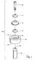
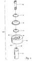
- FIG. 1is an exploded view of the components of an adjustable locking mount system that embodies features of the invention, in which the mounting hub is centric.
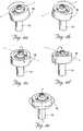
- FIG. 2is an assembled perspective view of the system shown in FIG. 1 .
- FIG. 3 ais a side sectional view of the assembled components of the system shown in FIG. 2 .
- FIG. 3 bis a view similar to FIG. 3 a and illustrating the spherical radii of the stacked washers.
- FIGS. 4 a - 4 eillustrate rotational movement of the cooperating components of the assembled system shown in FIG. 2 .
- FIG. 5 ais a side sectional view of the assembled components of the system shown in FIG. 3 and illustrating the system components in a level position.
- FIG. 5 bis a sectional view as shown in FIG. 5 a , illustrating the position of the system components and the movement of the mounting hub and lock washer when the mounting hub is rotated about the x or y axis.
- FIG. 5 cis a sectional view as shown in FIG. 5 b , illustrating the procedure of locking the system in a desired position.
- FIG. 6is an exploded view of the components of an alternative embodiment of an adjustable locking mount system that embodies features of the invention, in which the mounting hub is eccentric.
- FIG. 7is an assembled perspective view of the system shown in FIG. 6 .
- FIG. 8is side sectional view of the assembled components of the system shown in FIG. 7 .
- FIGS. 9 a - 9 eillustrate rotational movement of the cooperating components of the assembled system shown in FIG. 7 .
- FIG. 10is an exploded view of the components of an alternative embodiment of an adjustable locking mount system that embodies features of the invention.
- FIG. 11is an assembled perspective view of assembled components of the system shown in FIG. 10 .
- FIG. 12is side sectional view of the assembled components of the system shown in FIG. 11 .
- FIG. 13is an exploded view of an alternative embodiment of an adjustable locking mount system that embodies features of the invention.
- FIG. 14is an assembled perspective view of the system shown in FIG. 13 .
- FIG. 15is side sectional view of the assembled components of the system in FIG. 13 .
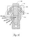
- FIGS. 16 a - 16 cillustrate movement of the cooperating parts of the assembled system shown in FIG. 14 .
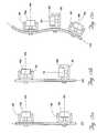
- FIGS. 17 a - 17 dillustrate various embodiments of composite mounting assemblies embodying features of the invention.
- FIG. 18is a perspective view of a wall, and illustrating an adjustable locking mount that embodies features of the invention mounted onto the wall and further illustrating a stereo speaker to be mounted on the mount.
- FIG. 19is view similar to FIG. 18 and illustrating the speaker mounted on the mount.
- FIG. 20is a view similar to FIG. 19 and illustrating the position of the speaker being adjusted by rocking and rotational movement.
- FIG. 1shows the individual components of an adjustable locking mounting system 10 A.
- FIGS. 2 and 3 aillustrate the system 10 A when assembled.
- the system 10 Apermits adjustment in three directions or three degrees of freedom (rotational around axes x, y, and z, where the z-axis is represented by the axis of the pivot pin 12 ) (see FIGS. 4 a - 4 e ).
- the system 10 Acomprises the pivot pin 12 , at least one slip washer 14 , at least one lock washer 16 , a mounting hub 18 , and a locking screw 20 .
- Each of these components of the system 10 Awill now be described in detail.
- the pivot pin 12is a rigid, generally cylindrical or rod-like member.
- the pivot pin 12is convex, e.g., domed, at one end to couple with the mounting hub 18 (see, e.g., FIG. 3 a ).
- the arc of curvatureis 0.400′′ diameter (0.200′′ radius).
- the convex arrangementpermits adjustment of the mounting hub 18 by swinging or tilting across the axis of the pivot pin 12 (i.e., rotation about the x-axis and y-axis) as well as by rotating or twisting about the axis of the pivot pin 12 (i.e., rotation about the z-axis) (see FIGS. 4 a - 4 e ).
- the pivot pin 12has a threaded central bore 26 that serves to receive the locking screw 20 .
- the pivot pin 12serves to receive both the mounting hub 18 and the locking screw 20 (see FIG. 3 a ).
- the pivot pin 12can be made of suitable metal, plastic, or ceramic materials and formed by conventional molding or machining techniques.
- the mounting hub 18is a rigid member comprising a mounting surface 24 , an interior hub 22 , and an exterior pivot surface 28 .
- the center of the mounting hub 18serves to receive the locking screw 20 .
- the mounting surface 24is configured to mate with an object or device being mounted on the hub and therefore can take on a variety of shapes.
- the mounting hub 18serves as a base for mounting of another object or device.
- the mounting surface 24can be circular or geometric. In the illustrated embodiment, the mounting surface 24 is generally circular.
- the mounting surface 24can be stepped to further aid in positioning and securing the object or device on the mounting surface 24 (not shown).
- the object or device being mountedwould have a complementary stepped surface.
- the stepped surfaceprovides greater control of any adjustment by permitting adjustment to be in uniform increments and reducing the risk of inadvertent movement.
- the mounting surface 24could alternatively be a threaded surface to facilitate engagement with a mating part.
- the interior hub 22is open.
- the bottom surface of the interior hub 22is configured to conform to the shape of the convex end of the pivot pin 12 and sized to receive the slip washer(s) 14 and lock washer(s) 16 . That is, the interior hub 22 permits a slip washer 14 and lock washer 16 , or multiple slip washers 14 and lock washers 16 , to be alternately stacked upon one another (see FIG. 3 a ).
- the exterior pivot surface 28 of the mounting hub 18is configured to nest on and to conform to the convex end of the pivot pin 12 , thus permitting a wider range of motion, as previously described.
- the exterior pivot surface 28is located centrally with respect to the interior hub 22 . Further, the interior hub 22 is centrally located with respect to the mounting surface 24 , such that the geometric center of the mounting hub 18 coincides with the center of rotation of the mounting hub 18 about the pivot pin 12 .
- the mounting hub 18serves to engage and pivot about the pivot pin 12 , thus permitting adjustment of the position of the mounting hub 18 with respect to the pivot pin 12 , as will be described later.
- the position of the mounting hub 18can be locked by use of the locking screw 20 , as will also be described in greater detail later.
- the mounting hub 18can be made of any suitable metal or plastic and formed by conventional machining or molding techniques.
- the system 10 Aalso provides at least one slip washer 14 .
- the slip washer 14is preferably a rigid annular ring or doughnut-like member. As FIGS. 1 and 3 a best show, the slip washer 14 is configured to conform to the bottom surface of the interior hub 22 .
- the center of the slip washer 14serves to receive the locking screw 20 .
- the center of the slip washer 14is of a diameter only slightly larger than the outside diameter of the locking screw 20 .
- the slip washer 14also serves to provide a frictional surface, which upon tightening of the locking screw 20 , serves to further secure the mounting hub 18 in a desired position.
- the slip washer 14permits the lock washer 16 to slide across the surface of the slip washer 14 (see FIGS. 5 a and 5 b ).
- the slip washer 14is similar in function yet physically different in top and bottom spherical radii from the lock washer 16 .
- R 1 -R 5spherical radii
- R 1is 0.200
- R 2is 0.250
- R 3is 0.300
- R 4is 0.350
- R 5is 0.400.
- the radii of the washers 14 and 16can be varied to accommodate the thickness of the individual washers 14 and 16 . Regardless of the thickness or radii of the washers 14 and 16 , the washers 14 and 16 are configured to rotate about the same pivot point.
- a second slip washer 14similar in function but differing in spherical radii from the first slip washer 14 is placed over the lock washer 16 .
- the lock washer 16is able to slide between the slip washers 14 .
- the second slip washer 14provides an additional frictional surface, which upon tightening of the locking screw 20 , serves to further secure the desired position.
- the slip washer(s) 14can be made of any suitable metal or plastic and formed by conventional machining or molding techniques.
- the system 10 Afurther provides a lock washer 16 .
- the lock washer 16is a rigid, annular ring or doughnut-like member similar to the slip washer 14 .
- the lock washer 16is configured to conform to the surface of the slip washer 14 . This arrangement permits the lock washer 16 to be stacked on top of the slip washer 14 .
- the center of the lock washer 16serves to receive the locking screw 20 .
- the center of the lock washer 16is also sized larger than the center of the slip washer 14 . That is, the center of the lock washer 16 not only serves to receive the locking screw 20 , but also permits the lock washer 16 to pivot about the pivot pin 12 .
- the lock washer 16also provides two additional frictional surfaces when sandwiched between two slip washers 14 , which upon tightening of the locking screw 20 , serve to further secure the desired position.
- the lock washer 16is of a larger diameter than the slip washer 14 .
- This arrangementallows the lock washer 16 to fit over the slip washer 14 .
- the lock washer 16is sized to approximate or be slightly less than the diameter of the interior hub 22 , thereby providing a secure fit of the lock washer 16 within the interior hub 22 and allowing only minimal translation in the x and y axes, yet not restricting z-axis translation of the lock washer 16 within the interior hub 22 and with respect to the axis of the pivot pin 12 , as will later be described in detail.
- This arrangementsecures/couples the lock washer 16 to the interior hub 22 and permits the lock washer 16 to slide with the mounting hub 18 over the slip washer 14 (see, e.g., FIGS. 5 a and 5 b ).
- the lock washer 16serves to provide an additional rotational and rocking surface for the mounting hub 18 .
- the lock washer 16can be made of any suitable plastic or metal and formed by conventional molding or machining techniques.
- a second slip washer 14 similar in function but differing in spherical radii from the first slip washer 14can be provided.
- the lock washer 16also serves to receive the second slip washer 14 . It will be apparent that any number of slip washers 14 and lock washers 16 can be similarly alternately stacked upon each other and thereby accommodate variations in the depth of the interior hub 22 .
- the system 10 Aprovides a locking screw 20 .
- the locking screw 20is a screw that is adapted for passage through the mounting hub 18 , the slip washer(s) 14 , the lock washer(s) 16 , and the pivot pin 12 when the system is assembled (see FIG. 3 a ).
- In inside the diameter of the slip washer 14is sized to approximate or be slightly larger than the diameter of the locking screw 20 . This arrangement secures/couples the slip washer 14 to the locking screw 20 and the pivot pin 12 .
- the locking screw 20is desirably threaded to fit the threaded bore 26 of the pivot pin 12 .
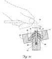
- FIG. 5 cillustrates, rotation (represented by arrow in FIG. 5 c ) of the screw 20 , e.g., by an Allen wrench 30 , advances the screw into the pivot pin 12 to fix the mounting hub 18 in a desired position.
- the locking screw 20can be made of any suitable plastic or metal and formed by conventional molding or machining techniques.
- the locking screw 20when not fully tightened, serves to hold the assembly while the desired position is determined. Tightening of the locking screw 20 compresses the washers 14 and 16 , hub 18 , and pin 12 together, thereby creating multiple frictional forces between the mating surfaces. These frictional forces and the compression of the screw 20 are what limit movement in the locked position.
- plastic slip washers 14may be alternated with metal lock washers 16 .
- the system 10 A as previously describedenables the mounting hub 18 to be oriented in a variety of directions with respect to the pivot pin 12 .
- the types of movement, and thus the types of adjustments permitted,will now be discussed.
- the system 10 Apermits movement of the mounting hub 18 in at least three rotational directions.
- the mounting hub 18can be rocked or rotated, i.e., tilted, about the x-axis (i.e., side to side rotation). This motion is permitted by the convex surfaces of the pivot pin 12 , mounting hub 18 , slip washer(s) 14 , and lock washer(s) 16 .
- the mounting hub 18can be rocked or rotated, i.e., tilted, about the y-axis (i.e., front to back rotation). This motion is permitted by the convex surfaces of the pivot pin 12 , mounting hub 18 , slip washer(s) 14 , and lock washer(s) 16 .
- the mounting hub 18can be rotated 360° in either a clockwise or counterclockwise direction about the z-axis (i.e., axis of the pivot pin 12 ).
- FIG. 6shows the individual components of an alternative system 10 B providing an adjustable locking mount system.
- FIGS. 7 and 8illustrate the system 10 B when assembled.
- system 10 Bcomprises a pivot pin 12 , at least one slip washer 14 , at least one lock washer 16 , a mounting hub 18 , and a locking screw 20 .
- the mounting hub 18has an exterior pivot surface 28 that is located centrally with respect to the interior hub 22 .
- the interior hub 22is eccentric with respect to the mounting surface 24 , such that the geometric center of the mounting hub 18 does not coincide with the center of rotation of the mounting hub 18 about the pivot pin 12 .
- the eccentric configurationpermits a broader range of adjustment.
- the system 10 B as previously describedenables the mounting hub 18 to be oriented in a variety of directions with respect to the pivot pin 12 .
- the types of movement, and thus the types of adjustments permitted,will now be discussed.
- the system 10 Bpermits movement of the mounting hub 18 in at least five directions.
- the mounting hub 18can be rocked or rotated about the x-axis, as previously described for system 10 A.
- the mounting hub 18can be rocked or rotated about the y-axis, as also previously described for system 10 A.
- the mounting hub 18can be rotated up to 360° in either direction about the z-axis, as previously described for system 10 A.
- the mounting hub 18when the mounting hub 18 includes an interior hub 22 that is eccentric relative to the mounting surface 24 , the distance from the pivot pin 12 to the mounting surface 24 increases to a maximum value, depicted as point A 1 and then decreases to a minimum value, depicted as point A 2 .
- Reorientation of points A 1 and A 2 with respect to the x-axisprovides a fourth degree of freedom.
- reorientation of points A 1 and A 2 with respect to the y-axisprovides a fifth degree of freedom.
- the locking screw 20is tightened to secure the mounting hub 18 in the desired position, as previously described for System 10 A (see FIG. 5 c ).
- FIG. 10shows the individual components of an alternative system 10 C providing an adjustable locking mount system that restricts rotation about the z-axis when locked.
- FIGS. 11 and 12illustrate the system 10 C when assembled.
- the system 10 Ccomprises a pivot pin 12 , three slip washers 14 , two lock washers 16 , a mounting hub 18 , and a fastener 21 , e.g., a nut. While the illustrated embodiment depicts a five-washer system, a greater or lesser number of slip washers 14 and lock washers 16 can be provided, as previously described.
- lock washer 16As best seen in FIG. 10, the outside surface of lock washer 16 and the inside surface of the interior hub 22 of mounting hub 18 have mating surfaces. This arrangement essentially prevents any rotation between the lock washers 16 and the mounting hub 18 .
- pivot pin 12has a post 35 protruding from the top with an outer diameter shaped to mate with a similarly-shaped inner diameter on the slip washers 14 to prevent rotation between the post 35 and the slip washers 14 .
- the outside surface of the lock washer, the inner surface of the interior hub 22 , and the post 35have complementary hexagonal configurations.
- This arrangementpermits all degrees of freedom as previously described for systems 10 A and 10 B, but has additional restriction to movement about the z-axis when in the locked position.
- Tightening of the fastener 21serves to secure the mounting hub 18 in the desired position, as previously described for Systems 10 A and 10 B.
- FIG. 13shows the individual components of an alternative system 10 D providing an adjustable locking mount system that provides rotational movement about the z-axis and linear movement along the x and y axes.
- FIGS. 14-15illustrate the system 10 D when assembled.
- system 10 Dcomprises a pivot pin 12 , three slip washers 14 , two lock washers 16 , a mounting hub 18 , and a locking screw 20 .
- the inventionalso contemplates embodiments having a greater or lesser number of slip washers 14 and lock washers 16 .
- pivot pin 12slip washers 14
- lock washers 16and mounting hub 18 each have flat surfaces.
- this arrangementpermits 360° rotational movement in either a clockwise or counterclockwise direction about the z-axis (i.e., axis of the pivot pin 12 ).
- the mounting hub 18can also be moved linearly along the x-axis (i.e., side to side translation).
- the mounting hub 18can also be moved linearly along the y-axis (i.e., front to back translation), as represented by arrows and phantom lines in FIG. 16 c .
- rotational ranges of motion along the x and y axesare essentially prevented.
- the adjustable mount of any of the systems 10 A- 10 D just describedcan be used alone as a single mount. Alternatively, multiple mounts can be coupled together to form a composite mounting assembly. Further, mounts of different systems can be coupled together. For example, a mount of the type of system 10 A could be coupled to a mount or mounts of the type of system 10 B. It is apparent that any number of mounts can be coupled together.
- FIGS. 17 a - 17 dprovide examples of three such composite mounting assemblies contemplated by the invention.
- a series of multiple mounting frames 98each house an adjustable mount having a mounting hub 18 , as described for any of the systems 10 A- 10 D.
- the frames 98are attached along an orientation axis, designated OA in FIGS. 17 a - 17 d .
- the orientation axis OAcan be linear (see FIGS. 17 a , 17 b , and 17 d ) or curvilinear (see FIG. 17 c ).
- adjacent frames 98can be joined in a fixed relationship by various methods, e.g., fastener, weld, or spacing member. That is, the frames 98 can be coupled side-by-side or in a spaced-apart relationship. In the embodiments shown in FIGS. 17 a - 17 c , a spaced-apart relationship is employed. Alternately, as seen in FIG. 17 d , a mounting hub 18 can be joined, either directly or through a spacing member, to an adjacent frame 98 .
- Each mounting hub 18has a pivot axis, designated PA in FIGS. 17 a - 17 d .
- the pivot axis PAcan either extend generally along the orientation axis OA or be generally transverse to the orientation axis OA.
- FIG. 17 aillustrates an arrangement in which first and second mounting hubs 18 a and 18 b have pivot axes PA generally transverse to the orientation axis OA.
- mounting hub 18 ahas a pivot axis PA generally transverse to the orientation axis OA
- mounting hub 18 bhas a pivot axis PA that generally extends along the orientation axis OA.
- FIGS. 17 c and 17 dshow embodiments having first, second, and third mounting hubs 18 a , 18 b , and 18 c .
- mounting hubs 18 a and 18 bhave pivot axes PA generally transverse to the orientation axis OA
- mounting hub 18 chas a pivot axis PA that generally extends along the orientation axis OA.
- Any of the systems 10 A- 10 Dare suitable for use in mounting an object or device on another object, device, or structure.
- An illustration of one such usewill now be provided. It is to be understood that the following example is merely illustrative and that features of the invention can be employed in an infinite number of circumstances to mount a variety of objects and devices onto various objects, devices, and structures.
- FIGS. 18-20detail the use of an adjustable mount of the type described for systems 10 A- 10 D to mount a stereo speaker 36 on a wall 39 .
- the mount of system 10 Ais employed.
- the system 10 Ais first fixed onto a wall 39 using a mounting base 41 .
- the locking screw 20is tightened enough to secure the assembled system 10 A, but loose enough to permit adjustment of the mounting hub 18 .
- a mounting bracket 37is then coupled to the mounting hub 18 .
- the stereo speaker 36is mounted onto the mounting hub 18 using the mounting bracket 37 .
- the position of the speaker 36is adjusted.
- the position of the speaker 36is adjusted by a combination of rotational and rocking movement along the x, y, and z axes as permitted until the desired position is obtained, as illustrated by arrows and phantom lines in FIG. 20 .
- This arrangementpermits the position of the speaker 36 to subsequently be selectively adjusted, i.e., does not secure or fix the speaker 36 in a desired position.
- the speaker 36can be secured in a desired position.
- the system 10 Ais first fixed onto a wall 39 , as previously described (see FIG. 18 ).
- the position of the mounting hub 18is adjusted until the desired position is obtained (see, e.g., FIGS. 4 a - 4 e ).
- the desired positionis fixed by tightening the locking screw 20 (see FIG. 5 c ).
- the speaker 36is mounted onto the mounting hub 18 , as previously described (see FIG. 19 ).
- This arrangementsecures the speaker 36 in a fixed position, i.e., does not permit subsequent selective adjustment of the position of the speaker 36 without release of the locking screw.
- a composite mounting assemblycan be employed to mount a series of objects or devices, e.g., track lighting (not shown).
Landscapes
- Engineering & Computer Science (AREA)
- General Engineering & Computer Science (AREA)
- Mechanical Engineering (AREA)
- Pivots And Pivotal Connections (AREA)
- Vehicle Body Suspensions (AREA)
- Vibration Prevention Devices (AREA)
- Fluid-Damping Devices (AREA)
Abstract
Description
Claims (10)
Priority Applications (8)
| Application Number | Priority Date | Filing Date | Title |
|---|---|---|---|
| US10/041,707US6688798B2 (en) | 2001-02-27 | 2002-01-08 | Adjustable locking mount and methods of use |
| PCT/US2002/001078WO2002068857A2 (en) | 2001-02-27 | 2002-01-16 | Adjustable locking mount and methods of use |
| AU2002239920AAU2002239920A1 (en) | 2001-02-27 | 2002-01-16 | Adjustable locking mount and methods of use |
| US10/340,347US6929418B2 (en) | 2002-01-08 | 2003-01-10 | Adjustable locking mount |
| US10/342,807US6729794B2 (en) | 2002-01-08 | 2003-01-15 | Adjustable locking mount and methods of use |
| PCT/US2004/000539WO2004063497A2 (en) | 2002-01-08 | 2004-01-12 | Adjustable locking mount |
| PCT/US2004/000776WO2004065808A2 (en) | 2002-01-08 | 2004-01-13 | Adjustable locking mount and methods of use |
| US10/760,444US6896436B2 (en) | 2001-02-27 | 2004-01-20 | Adjustable locking mount and methods of use |
Applications Claiming Priority (2)
| Application Number | Priority Date | Filing Date | Title |
|---|---|---|---|
| US27189501P | 2001-02-27 | 2001-02-27 | |
| US10/041,707US6688798B2 (en) | 2001-02-27 | 2002-01-08 | Adjustable locking mount and methods of use |
Related Child Applications (3)
| Application Number | Title | Priority Date | Filing Date |
|---|---|---|---|
| US10/340,347Continuation-In-PartUS6929418B2 (en) | 2002-01-08 | 2003-01-10 | Adjustable locking mount |
| US10/342,807Continuation-In-PartUS6729794B2 (en) | 2002-01-08 | 2003-01-15 | Adjustable locking mount and methods of use |
| US10/760,444DivisionUS6896436B2 (en) | 2001-02-27 | 2004-01-20 | Adjustable locking mount and methods of use |
Publications (2)
| Publication Number | Publication Date |
|---|---|
| US20020116789A1 US20020116789A1 (en) | 2002-08-29 |
| US6688798B2true US6688798B2 (en) | 2004-02-10 |
Family
ID=26718435
Family Applications (2)
| Application Number | Title | Priority Date | Filing Date |
|---|---|---|---|
| US10/041,707Expired - Fee RelatedUS6688798B2 (en) | 2001-02-27 | 2002-01-08 | Adjustable locking mount and methods of use |
| US10/760,444Expired - Fee RelatedUS6896436B2 (en) | 2001-02-27 | 2004-01-20 | Adjustable locking mount and methods of use |
Family Applications After (1)
| Application Number | Title | Priority Date | Filing Date |
|---|---|---|---|
| US10/760,444Expired - Fee RelatedUS6896436B2 (en) | 2001-02-27 | 2004-01-20 | Adjustable locking mount and methods of use |
Country Status (3)
| Country | Link |
|---|---|
| US (2) | US6688798B2 (en) |
| AU (1) | AU2002239920A1 (en) |
| WO (1) | WO2002068857A2 (en) |
Cited By (7)
| Publication number | Priority date | Publication date | Assignee | Title |
|---|---|---|---|---|
| US20040247378A1 (en)* | 2002-07-22 | 2004-12-09 | Sarkisian Mark P. | Seismic structural device |
| US20080004710A1 (en)* | 2006-06-30 | 2008-01-03 | Howmedica Osteonics Corp. | Femoral head resurfacing |
| US20080109085A1 (en)* | 2006-11-03 | 2008-05-08 | Howmedica Osteonics Corp. | Method and apparatus for hip femoral resurfacing tooling |
| USD579585S1 (en) | 2007-03-23 | 2008-10-28 | Peak Innovations Inc. | Adjustable post support |
| US20080302938A1 (en)* | 2007-06-08 | 2008-12-11 | Blue Sky Designs, Inc. | Mounting and positioning apparatus for increased user independence |
| US20110000051A1 (en)* | 2009-07-01 | 2011-01-06 | Huang-Kai Liang | Bath Curtain Rack Structure |
| US20210033244A1 (en)* | 2019-07-30 | 2021-02-04 | Fourth Arrow, LLC | Mount for tree stand |
Families Citing this family (34)
| Publication number | Priority date | Publication date | Assignee | Title |
|---|---|---|---|---|
| US6736852B2 (en)* | 2001-02-27 | 2004-05-18 | Incumed, Inc. | Adjustable bone prostheses and related methods |
| DE10163318C1 (en)* | 2001-12-21 | 2003-08-28 | Mekra Lang Gmbh & Co Kg | Articulated device in particular for adjusting rear view mirrors for motor vehicles |
| EP2281665B1 (en)* | 2003-09-10 | 2017-04-12 | Makita Corporation | Vibration isolating handle |
| US8419798B2 (en)* | 2003-12-30 | 2013-04-16 | Depuy Products, Inc. | Joint prosthesis with infinitely positionable head |
| US20060159375A1 (en)* | 2005-01-18 | 2006-07-20 | Swaminathan Krishnan | Inverted ball joint |
| US7241069B2 (en)* | 2005-02-07 | 2007-07-10 | Harald Richter | Universal joint arrangement between an apparatus holder and a support arm or a console |
| DE202005001986U1 (en)* | 2005-02-07 | 2005-04-14 | Richter, Harald | Universal joint arrangement between a device holder and a support arm or a console |
| US7455271B2 (en)* | 2005-08-17 | 2008-11-25 | Rgb Systems, Inc. | Method and apparatus for adjustably mounting a speaker |
| EP2155494A4 (en)* | 2007-06-14 | 2010-08-11 | Massachusetts Inst Technology | METHOD AND APPARATUS FOR REGULATING A FILM DEPOSITION |
| US7878477B2 (en)* | 2008-01-02 | 2011-02-01 | Lang-Mekra North America, Llc | Multi-axis pivoting detent joint assembly for an exterior vehicle mirror |
| US7686274B2 (en)* | 2008-04-17 | 2010-03-30 | Lang-Mekra North America Llc | Pivoting detent joint |
| US8383202B2 (en) | 2008-06-13 | 2013-02-26 | Kateeva, Inc. | Method and apparatus for load-locked printing |
| US10434804B2 (en) | 2008-06-13 | 2019-10-08 | Kateeva, Inc. | Low particle gas enclosure systems and methods |
| US12064979B2 (en) | 2008-06-13 | 2024-08-20 | Kateeva, Inc. | Low-particle gas enclosure systems and methods |
| US12018857B2 (en) | 2008-06-13 | 2024-06-25 | Kateeva, Inc. | Gas enclosure assembly and system |
| US11975546B2 (en) | 2008-06-13 | 2024-05-07 | Kateeva, Inc. | Gas enclosure assembly and system |
| USD658316S1 (en)* | 2008-08-29 | 2012-04-24 | D-Light Device B.V. | Sticker and candle combination |
| US20100188457A1 (en)* | 2009-01-05 | 2010-07-29 | Madigan Connor F | Method and apparatus for controlling the temperature of an electrically-heated discharge nozzle |
| EP2425470A2 (en)* | 2009-05-01 | 2012-03-07 | Kateeva, Inc. | Method and apparatus for organic vapor printing |
| US8491667B2 (en) | 2011-04-08 | 2013-07-23 | Timothy R Dillingham | Modular prosthesis system |
| US8845755B2 (en) | 2011-04-08 | 2014-09-30 | Ifit Prosthetics, Llc | Modular prosthetic devices and prosthesis system |
| US8470050B2 (en) | 2011-04-08 | 2013-06-25 | Timothy R. Dillingham | Rapid fit modular prosthetic device for accommodating gait alignment and residual limb shape and volume |
| US10398577B2 (en) | 2011-04-08 | 2019-09-03 | Ifit Prosthetics, Llc | Modular prosthetic devices and prosthesis systems |
| US11382775B2 (en) | 2011-04-08 | 2022-07-12 | Ifit Prosthetics, Llc | Modular prosthetic devices and prosthesis systems |
| US10806608B2 (en) | 2011-04-08 | 2020-10-20 | Ifit Prosthetics, Llc | Prosthetic method and apparatus |
| DE202011050832U1 (en)* | 2011-07-28 | 2011-09-05 | Leuze Electronic Gmbh + Co. Kg | sensor |
| WO2013056201A1 (en)* | 2011-10-14 | 2013-04-18 | Dillingham Timothy R | Rapid fit modular prosthetic device for accommodating gait alignment and residual limb shape and volume |
| GB2495727A (en)* | 2011-10-18 | 2013-04-24 | Neil Schofield | Mirror movable between mounting locations |
| US20130149023A1 (en)* | 2011-12-09 | 2013-06-13 | United Technologies Corporation | Adjustable clevis assembly |
| US10468279B2 (en) | 2013-12-26 | 2019-11-05 | Kateeva, Inc. | Apparatus and techniques for thermal treatment of electronic devices |
| KR102307190B1 (en) | 2014-01-21 | 2021-09-30 | 카티바, 인크. | Apparatus and techniques for electronic device encapsulation |
| EP3882961B1 (en) | 2014-04-30 | 2023-07-26 | Kateeva, Inc. | Gas cushion apparatus and techniques for substrate coating |
| EP3636466B1 (en)* | 2018-10-12 | 2021-04-07 | IQAir AG | Adaptor plate for an air purifying apparatus for use in vehicles |
| CN109579929A (en)* | 2018-11-22 | 2019-04-05 | 广州市富鑫机械设备有限公司 | A kind of flow detection fixture |
Citations (32)
| Publication number | Priority date | Publication date | Assignee | Title |
|---|---|---|---|---|
| US362384A (en) | 1887-05-03 | johnson | ||
| US1446164A (en) | 1920-04-01 | 1923-02-20 | D Eyraud Louis | Universal mounting device |
| US1538340A (en) | 1923-08-11 | 1925-05-19 | Hodny William La | Windshield-mirror bracket |
| US4051924A (en) | 1975-10-15 | 1977-10-04 | Yoshigai Kikai Kinzoku Kabushiki Kaisha | Device for mounting brake shoe of brake for bicycle |
| US4475314A (en)* | 1978-10-06 | 1984-10-09 | Daimler-Benz Aktiengesellschaft | Mounting arrangement by means of guide members for a transparent windowpane |
| US4669766A (en) | 1984-02-10 | 1987-06-02 | Hanchett Entry Systems, Inc. | Door holding magnet |
| US4722502A (en) | 1985-10-02 | 1988-02-02 | American Sterilizer Company | Adjustable support system |
| US5195710A (en) | 1990-10-30 | 1993-03-23 | Alcatel Telspace | Three-dimensional fixing device |
| US5425782A (en) | 1992-03-11 | 1995-06-20 | Phillips; Van L. | Alignment fixture for prosthetic device |
| US5562737A (en) | 1993-11-18 | 1996-10-08 | Henry Graf | Extra-discal intervertebral prosthesis |
| US5623742A (en)* | 1994-03-23 | 1997-04-29 | Paul Journee, S.A. | Motor vehicle screen wiper having means for orientation of the drive head |
| EP0791330A2 (en) | 1996-02-20 | 1997-08-27 | Cardiothoracic Systems, Inc. | Surgical instruments and procedures for stabilizing the beating heart during coronary artery bypass graft surgery |
| US5723018A (en) | 1992-11-17 | 1998-03-03 | Cyprien; Jean-Maxwell | Shoulder-joint endoprosthesis |
| WO1998008468A1 (en) | 1996-08-30 | 1998-03-05 | Hunter Innovations, Inc. | Adjustable modular orthopedic implant |
| US5725597A (en) | 1995-11-09 | 1998-03-10 | Hwang; Sung Kwan | Artificial hip-joint |
| US5727569A (en) | 1996-02-20 | 1998-03-17 | Cardiothoracic Systems, Inc. | Surgical devices for imposing a negative pressure to fix the position of cardiac tissue during surgery |
| WO1998049947A1 (en) | 1997-05-07 | 1998-11-12 | Riess Andreas G | Device for locally immobilizing a beating heart |
| WO1999016367A1 (en) | 1997-09-26 | 1999-04-08 | Alliance Medical Technologies, Inc. | Stabilizer |
| US5895428A (en) | 1996-11-01 | 1999-04-20 | Berry; Don | Load bearing spinal joint implant |
| EP0920835A1 (en) | 1997-10-07 | 1999-06-09 | Ethicon Endo-Surgery, Inc. | A tissue stabilization device for use during surgery |
| US5921695A (en)* | 1997-12-23 | 1999-07-13 | Ingersoll-Rand Company | Ergonomically adjustable tool handle having a dual direction locking device |
| WO2000015119A2 (en) | 1998-09-15 | 2000-03-23 | Medtronic, Inc. | Method and apparatus for temporarily immobilizing a local area of tissue |
| US6083263A (en) | 1991-08-23 | 2000-07-04 | Draenert; Klaus | Adjustable hip-joint endoprosthesis |
| US6123706A (en) | 1997-12-17 | 2000-09-26 | Lange; Robert | Apparatus for stabilizing certain vertebrae of the spine |
| US6171039B1 (en) | 1999-05-11 | 2001-01-09 | Nokia Telecommunications Oy | Locking mechanism for connector |
| WO2001006909A2 (en) | 1999-07-23 | 2001-02-01 | Ethicon, Inc. | System and method for attaching soft tissue to bone |
| US6197063B1 (en) | 1997-04-11 | 2001-03-06 | Smith & Nephew, Inc. | Modular humeral prosthesis and method |
| US6228120B1 (en) | 1998-01-09 | 2001-05-08 | Alain Leonard | Surgical equipment for implanting a total shoulder prosthesis, and total shoulder prosthesis constituting same |
| US6241730B1 (en) | 1997-11-26 | 2001-06-05 | Scient'x (Societe A Responsabilite Limitee) | Intervertebral link device capable of axial and angular displacement |
| US6248132B1 (en) | 1999-10-29 | 2001-06-19 | Charles C. Harris | Hip replacement prosthesis |
| US6273390B1 (en)* | 1999-10-20 | 2001-08-14 | Royal Capital Stamping And Tooling Ltd. | Post holder with upright adjustment |
| US6302887B1 (en) | 1998-07-20 | 2001-10-16 | Joseph John Spranza | Hardware for high strength fastening of bone |
Family Cites Families (1)
| Publication number | Priority date | Publication date | Assignee | Title |
|---|---|---|---|---|
| US6439802B1 (en)* | 1998-01-09 | 2002-08-27 | Barrier Systems, Inc. | Interconnected telescoping movable roadway barrier modules |
- 2002
- 2002-01-08USUS10/041,707patent/US6688798B2/ennot_activeExpired - Fee Related
- 2002-01-16AUAU2002239920Apatent/AU2002239920A1/ennot_activeAbandoned
- 2002-01-16WOPCT/US2002/001078patent/WO2002068857A2/ennot_activeApplication Discontinuation
- 2004
- 2004-01-20USUS10/760,444patent/US6896436B2/ennot_activeExpired - Fee Related
Patent Citations (32)
| Publication number | Priority date | Publication date | Assignee | Title |
|---|---|---|---|---|
| US362384A (en) | 1887-05-03 | johnson | ||
| US1446164A (en) | 1920-04-01 | 1923-02-20 | D Eyraud Louis | Universal mounting device |
| US1538340A (en) | 1923-08-11 | 1925-05-19 | Hodny William La | Windshield-mirror bracket |
| US4051924A (en) | 1975-10-15 | 1977-10-04 | Yoshigai Kikai Kinzoku Kabushiki Kaisha | Device for mounting brake shoe of brake for bicycle |
| US4475314A (en)* | 1978-10-06 | 1984-10-09 | Daimler-Benz Aktiengesellschaft | Mounting arrangement by means of guide members for a transparent windowpane |
| US4669766A (en) | 1984-02-10 | 1987-06-02 | Hanchett Entry Systems, Inc. | Door holding magnet |
| US4722502A (en) | 1985-10-02 | 1988-02-02 | American Sterilizer Company | Adjustable support system |
| US5195710A (en) | 1990-10-30 | 1993-03-23 | Alcatel Telspace | Three-dimensional fixing device |
| US6083263A (en) | 1991-08-23 | 2000-07-04 | Draenert; Klaus | Adjustable hip-joint endoprosthesis |
| US5425782A (en) | 1992-03-11 | 1995-06-20 | Phillips; Van L. | Alignment fixture for prosthetic device |
| US5723018A (en) | 1992-11-17 | 1998-03-03 | Cyprien; Jean-Maxwell | Shoulder-joint endoprosthesis |
| US5562737A (en) | 1993-11-18 | 1996-10-08 | Henry Graf | Extra-discal intervertebral prosthesis |
| US5623742A (en)* | 1994-03-23 | 1997-04-29 | Paul Journee, S.A. | Motor vehicle screen wiper having means for orientation of the drive head |
| US5725597A (en) | 1995-11-09 | 1998-03-10 | Hwang; Sung Kwan | Artificial hip-joint |
| EP0791330A2 (en) | 1996-02-20 | 1997-08-27 | Cardiothoracic Systems, Inc. | Surgical instruments and procedures for stabilizing the beating heart during coronary artery bypass graft surgery |
| US5727569A (en) | 1996-02-20 | 1998-03-17 | Cardiothoracic Systems, Inc. | Surgical devices for imposing a negative pressure to fix the position of cardiac tissue during surgery |
| WO1998008468A1 (en) | 1996-08-30 | 1998-03-05 | Hunter Innovations, Inc. | Adjustable modular orthopedic implant |
| US5895428A (en) | 1996-11-01 | 1999-04-20 | Berry; Don | Load bearing spinal joint implant |
| US6197063B1 (en) | 1997-04-11 | 2001-03-06 | Smith & Nephew, Inc. | Modular humeral prosthesis and method |
| WO1998049947A1 (en) | 1997-05-07 | 1998-11-12 | Riess Andreas G | Device for locally immobilizing a beating heart |
| WO1999016367A1 (en) | 1997-09-26 | 1999-04-08 | Alliance Medical Technologies, Inc. | Stabilizer |
| EP0920835A1 (en) | 1997-10-07 | 1999-06-09 | Ethicon Endo-Surgery, Inc. | A tissue stabilization device for use during surgery |
| US6241730B1 (en) | 1997-11-26 | 2001-06-05 | Scient'x (Societe A Responsabilite Limitee) | Intervertebral link device capable of axial and angular displacement |
| US6123706A (en) | 1997-12-17 | 2000-09-26 | Lange; Robert | Apparatus for stabilizing certain vertebrae of the spine |
| US5921695A (en)* | 1997-12-23 | 1999-07-13 | Ingersoll-Rand Company | Ergonomically adjustable tool handle having a dual direction locking device |
| US6228120B1 (en) | 1998-01-09 | 2001-05-08 | Alain Leonard | Surgical equipment for implanting a total shoulder prosthesis, and total shoulder prosthesis constituting same |
| US6302887B1 (en) | 1998-07-20 | 2001-10-16 | Joseph John Spranza | Hardware for high strength fastening of bone |
| WO2000015119A2 (en) | 1998-09-15 | 2000-03-23 | Medtronic, Inc. | Method and apparatus for temporarily immobilizing a local area of tissue |
| US6171039B1 (en) | 1999-05-11 | 2001-01-09 | Nokia Telecommunications Oy | Locking mechanism for connector |
| WO2001006909A2 (en) | 1999-07-23 | 2001-02-01 | Ethicon, Inc. | System and method for attaching soft tissue to bone |
| US6273390B1 (en)* | 1999-10-20 | 2001-08-14 | Royal Capital Stamping And Tooling Ltd. | Post holder with upright adjustment |
| US6248132B1 (en) | 1999-10-29 | 2001-06-19 | Charles C. Harris | Hip replacement prosthesis |
Cited By (11)
| Publication number | Priority date | Publication date | Assignee | Title |
|---|---|---|---|---|
| US20040247378A1 (en)* | 2002-07-22 | 2004-12-09 | Sarkisian Mark P. | Seismic structural device |
| US7000304B2 (en)* | 2002-07-22 | 2006-02-21 | Skidmore Owings & Merrill Llp | Seismic structural device |
| US20080004710A1 (en)* | 2006-06-30 | 2008-01-03 | Howmedica Osteonics Corp. | Femoral head resurfacing |
| US20100121458A1 (en)* | 2006-06-30 | 2010-05-13 | Howmedica Osteonics Corp. | Femoral head resurfacing |
| US20080109085A1 (en)* | 2006-11-03 | 2008-05-08 | Howmedica Osteonics Corp. | Method and apparatus for hip femoral resurfacing tooling |
| US8152855B2 (en) | 2006-11-03 | 2012-04-10 | Howmedica Osteonics Corp. | Method and apparatus for hip femoral resurfacing tooling |
| USD579585S1 (en) | 2007-03-23 | 2008-10-28 | Peak Innovations Inc. | Adjustable post support |
| US20080302938A1 (en)* | 2007-06-08 | 2008-12-11 | Blue Sky Designs, Inc. | Mounting and positioning apparatus for increased user independence |
| US8056874B2 (en) | 2007-06-08 | 2011-11-15 | Blue Sky Designs, Inc. | Mounting and positioning apparatus for increased user independence |
| US20110000051A1 (en)* | 2009-07-01 | 2011-01-06 | Huang-Kai Liang | Bath Curtain Rack Structure |
| US20210033244A1 (en)* | 2019-07-30 | 2021-02-04 | Fourth Arrow, LLC | Mount for tree stand |
Also Published As
| Publication number | Publication date |
|---|---|
| US20020116789A1 (en) | 2002-08-29 |
| US6896436B2 (en) | 2005-05-24 |
| WO2002068857A9 (en) | 2002-10-31 |
| AU2002239920A1 (en) | 2002-09-12 |
| WO2002068857A3 (en) | 2003-04-10 |
| WO2002068857A2 (en) | 2002-09-06 |
| US20040151535A1 (en) | 2004-08-05 |
Similar Documents
| Publication | Publication Date | Title |
|---|---|---|
| US6688798B2 (en) | Adjustable locking mount and methods of use | |
| US7523904B2 (en) | Locking ratchet base | |
| US7025315B2 (en) | Geodesic mounting apparatus | |
| US6729794B2 (en) | Adjustable locking mount and methods of use | |
| US4566663A (en) | Overhead pivotal mounting assembly for television set | |
| US4763151A (en) | Universal tripod head | |
| US7166132B2 (en) | Adjustable bone prostheses and related methods | |
| US7100881B2 (en) | Mount | |
| US6170965B1 (en) | Method and apparatus for locking a yoke or gimbal ring assembly | |
| US11732840B2 (en) | Mounting apparatus for an electronic device | |
| US20120217369A1 (en) | Support Apparatus | |
| JPH04211714A (en) | Turning additional tool | |
| US7461826B2 (en) | Lift truck base | |
| US7753329B2 (en) | Universal equipment mount | |
| WO2006122029A2 (en) | Adjustable mounting system for speaker enclosures | |
| EP0631674A1 (en) | Interlocking-body connective joint | |
| US20090090824A1 (en) | Support for assembly with flat panel video monitors, coupler for attachment of the support to an extension arm, and assembly methods | |
| JPH09214817A (en) | Stand for camera | |
| WO2004065808A2 (en) | Adjustable locking mount and methods of use | |
| US20250134737A1 (en) | An attachment system | |
| JP2005273760A (en) | Mounting mechanism | |
| CN2444367Y (en) | Fixtures for adjustable horn steering | |
| KR200291580Y1 (en) | Support for mirror | |
| JP2003281926A (en) | Hinge arrangement | |
| JP2001227527A (en) | Installing tool structure |
Legal Events
| Date | Code | Title | Description |
|---|---|---|---|
| AS | Assignment | Owner name:INCUMED, INC., NORTH CAROLINA Free format text:ASSIGNMENT OF ASSIGNORS INTEREST;ASSIGNOR:MCDEVITT, DENNIS;REEL/FRAME:012806/0402 Effective date:20020315 | |
| FPAY | Fee payment | Year of fee payment:4 | |
| AS | Assignment | Owner name:ORTHOVERT, INC., MINNESOTA Free format text:ASSIGNMENT OF ASSIGNORS INTEREST;ASSIGNORS:INCUMED INCORPORATED;VERTICAL FUND I, L.P.;VERTICAL FUND II, L.P.;AND OTHERS;REEL/FRAME:020083/0301 Effective date:20071102 | |
| AS | Assignment | Owner name:TORNIER, INC., MINNESOTA Free format text:ASSIGNMENT OF ASSIGNORS INTEREST;ASSIGNOR:ORTHOVERT, INC.;REEL/FRAME:021901/0314 Effective date:20081120 | |
| FEPP | Fee payment procedure | Free format text:PAT HOLDER NO LONGER CLAIMS SMALL ENTITY STATUS, ENTITY STATUS SET TO UNDISCOUNTED (ORIGINAL EVENT CODE: STOL); ENTITY STATUS OF PATENT OWNER: LARGE ENTITY | |
| FPAY | Fee payment | Year of fee payment:8 | |
| AS | Assignment | Owner name:BANK OF AMERICA, N.A., AS ADMINISTRATIVE AGENT, CA Free format text:PATENT SECURITY AGREEMENT;ASSIGNOR:TORNIER, INC.;REEL/FRAME:029076/0361 Effective date:20121004 | |
| REMI | Maintenance fee reminder mailed | ||
| AS | Assignment | Owner name:TORNIER, INC., MINNESOTA Free format text:TERMINATION AND RELEASE OF SECURITY INTEREST IN PATENTS;ASSIGNOR:BANK OF AMERICA, N.A., AS ADMINISTRATIVE AGENT;REEL/FRAME:036900/0672 Effective date:20151001 | |
| LAPS | Lapse for failure to pay maintenance fees | ||
| STCH | Information on status: patent discontinuation | Free format text:PATENT EXPIRED DUE TO NONPAYMENT OF MAINTENANCE FEES UNDER 37 CFR 1.362 | |
| FP | Lapsed due to failure to pay maintenance fee | Effective date:20160210 |