US6688743B1 - Method and apparatus to determine fly height of a recording head - Google Patents
Method and apparatus to determine fly height of a recording headDownload PDFInfo
- Publication number
- US6688743B1 US6688743B1US09/155,460US15546098AUS6688743B1US 6688743 B1US6688743 B1US 6688743B1US 15546098 AUS15546098 AUS 15546098AUS 6688743 B1US6688743 B1US 6688743B1
- Authority
- US
- United States
- Prior art keywords
- light
- detector module
- fly height
- measurement system
- disc
- Prior art date
- Legal status (The legal status is an assumption and is not a legal conclusion. Google has not performed a legal analysis and makes no representation as to the accuracy of the status listed.)
- Expired - Lifetime
Links
Images


Classifications
- G—PHYSICS
- G11—INFORMATION STORAGE
- G11B—INFORMATION STORAGE BASED ON RELATIVE MOVEMENT BETWEEN RECORD CARRIER AND TRANSDUCER
- G11B5/00—Recording by magnetisation or demagnetisation of a record carrier; Reproducing by magnetic means; Record carriers therefor
- G11B5/48—Disposition or mounting of heads or head supports relative to record carriers ; arrangements of heads, e.g. for scanning the record carrier to increase the relative speed
- G11B5/58—Disposition or mounting of heads or head supports relative to record carriers ; arrangements of heads, e.g. for scanning the record carrier to increase the relative speed with provision for moving the head for the purpose of maintaining alignment of the head relative to the record carrier during transducing operation, e.g. to compensate for surface irregularities of the latter or for track following
- G11B5/60—Fluid-dynamic spacing of heads from record-carriers
- G11B5/6005—Specially adapted for spacing from a rotating disc using a fluid cushion
- G—PHYSICS
- G01—MEASURING; TESTING
- G01B—MEASURING LENGTH, THICKNESS OR SIMILAR LINEAR DIMENSIONS; MEASURING ANGLES; MEASURING AREAS; MEASURING IRREGULARITIES OF SURFACES OR CONTOURS
- G01B11/00—Measuring arrangements characterised by the use of optical techniques
- G01B11/14—Measuring arrangements characterised by the use of optical techniques for measuring distance or clearance between spaced objects or spaced apertures
- G—PHYSICS
- G11—INFORMATION STORAGE
- G11B—INFORMATION STORAGE BASED ON RELATIVE MOVEMENT BETWEEN RECORD CARRIER AND TRANSDUCER
- G11B11/00—Recording on or reproducing from the same record carrier wherein for these two operations the methods are covered by different main groups of groups G11B3/00 - G11B7/00 or by different subgroups of group G11B9/00; Record carriers therefor
- G11B11/10—Recording on or reproducing from the same record carrier wherein for these two operations the methods are covered by different main groups of groups G11B3/00 - G11B7/00 or by different subgroups of group G11B9/00; Record carriers therefor using recording by magnetic means or other means for magnetisation or demagnetisation of a record carrier, e.g. light induced spin magnetisation; Demagnetisation by thermal or stress means in the presence or not of an orienting magnetic field
- G11B11/105—Recording on or reproducing from the same record carrier wherein for these two operations the methods are covered by different main groups of groups G11B3/00 - G11B7/00 or by different subgroups of group G11B9/00; Record carriers therefor using recording by magnetic means or other means for magnetisation or demagnetisation of a record carrier, e.g. light induced spin magnetisation; Demagnetisation by thermal or stress means in the presence or not of an orienting magnetic field using a beam of light or a magnetic field for recording by change of magnetisation and a beam of light for reproducing, i.e. magneto-optical, e.g. light-induced thermomagnetic recording, spin magnetisation recording, Kerr or Faraday effect reproducing
- G11B11/1055—Disposition or mounting of transducers relative to record carriers
- G11B11/1058—Flying heads
- G—PHYSICS
- G11—INFORMATION STORAGE
- G11B—INFORMATION STORAGE BASED ON RELATIVE MOVEMENT BETWEEN RECORD CARRIER AND TRANSDUCER
- G11B7/00—Recording or reproducing by optical means, e.g. recording using a thermal beam of optical radiation by modifying optical properties or the physical structure, reproducing using an optical beam at lower power by sensing optical properties; Record carriers therefor
- G11B7/12—Heads, e.g. forming of the optical beam spot or modulation of the optical beam
- G11B7/122—Flying-type heads, e.g. analogous to Winchester type in magnetic recording
- G—PHYSICS
- G11—INFORMATION STORAGE
- G11B—INFORMATION STORAGE BASED ON RELATIVE MOVEMENT BETWEEN RECORD CARRIER AND TRANSDUCER
- G11B7/00—Recording or reproducing by optical means, e.g. recording using a thermal beam of optical radiation by modifying optical properties or the physical structure, reproducing using an optical beam at lower power by sensing optical properties; Record carriers therefor
- G11B7/12—Heads, e.g. forming of the optical beam spot or modulation of the optical beam
- G11B7/135—Means for guiding the beam from the source to the record carrier or from the record carrier to the detector
- G11B7/1387—Means for guiding the beam from the source to the record carrier or from the record carrier to the detector using the near-field effect
Definitions
- the present inventionrelates to disc storage systems of the type used to store information. More specifically, the invention relates to an apparatus for determining fly height in a head/gimbal assembly of such a disc storage system.
- Disc storage systemsare known in the art and are used to store information for later retrieval. Such disc storage systems include a rotating disc which carries information thereon. A transducing head (or, in some instances, a read back head) is positioned over a surface of the disc while the disc rotates at high speed. The head is carried on a slider which is designed to “fly” just over the surface of the rotating disc. The head may then be used to write information from the disc. Such information may be, for example, magnetically or optically encoded of the disc surface.
- Fly heightis defined as the distance between the disc surface and the head or slider during operation of the storage system. A reduced fly height allows information to be written or read back more precisely and such information can be stored in a smaller area (i.e., at a higher density).
- fly heightis measured before assembling the head and slider assemblies into disc drives.
- One technique to measure fly heightis by measuring electrical capacitance between the head and the disc.
- Another common technique to measure fly heightis using optical interferometry in which a transparent test disc is used to fly the slider. Light is shined through the disc onto the slider from a source on the other side of the disc. Using known techniques, the reflected light can be examined to determine fly height.
- U.S. Pat. No. 5,280,340, issued Jan. 18, 1994 to Lacydescribes a number of such techniques for measuring fly height.
- Another technique used to measure and characterize a headis to measure the read back signal provided by the head during operation.
- the signalcan be examined for many different parameters, including signal strength, intersymbol interference, off-track sensitivity, etc.
- U.S. Pat. No. 5,068,754issued Nov. 26, 1991 describes a method and apparatus for measuring bit shift in a magnetic disc drive.
- Optical discsprovide an alternative to purely magnetic based recording media.
- Optical disc drivescan be used to obtain high storage densities.
- An approach to increase the storage densityinvolves reducing the spot size using near-field recording.
- Near-field recordinginvolves optical components mounted on a slider within a distance roughly on the order of a wavelength or less of the surface of the disc. Then, the energy transmitted through the optics is transferred to the surface of the disc through evanescent coupling.
- a Solid Immersion Lens (SIL) or the likecan be used along with an objective lens to produce an ultra small spot.
- SILSolid Immersion Lens
- optical storage systemsdata is in the form of marks carried on the surface of the disc which are detected using the reflected laser light.
- compact discsare currently used to store digital data such as computer programs or digitized music.
- compact discsare permanently recorded during manufacture.
- WORMwrite-once read-many
- Other types of systemsare erasable, such as phase change and magneto-optic (M-O) systems.
- Phase change systemsdetect data by sensing a change in reflectivity.
- M-O systemsread data by measuring the rotation of the incident light polarization due to the storage medium.
- the inventionfeatures a measurement system for estimating the fly height of a recording head relative to a spinning disc.
- the fly height measurement systemincludes a source of light, a slider, a detector module and a processor.
- the sliderincludes an objective lens positioned such that light from the source hits the objective lens and is directed to the surface of the disc.
- the detector modulereceives light reflected from the disc.
- the processorestimates the fly height of the slider based on detector module output.
- the detector modulereceives light transmitted through the disc. The transmitted light is not spatially dispersed based on wavelength. Again, the processor estimates the fly height based on detector module output.
- the inventionfeatures a method of determining fly height of a slider relative to spinning disc comprising:
- the detector module for performing the methodcan include a lens and a two element detector and wherein the fly height is estimated by evaluating the difference in signals from the two elements of the detector and comparing the difference with values from a standard curve.
- the detector modulecomprises a polarization beam splitter and two light sensitive elements each configured to measure one component of the split beam.
- the detector modulecomprises a detector array, and wherein the fly height is estimated by examining an intensity distribution, a phase distribution or a polarization distribution measured by the detector array.
- FIG. 1Ais a schematic diagram depicting a measuring system for determining the distance of a slider relative to a spinning disc.
- FIG. 1Bis a schematic diagram depicting an alternative embodiment of a measuring system for determining the distance of a slider relative to a spinning disc.
- FIG. 2is a sectional, side view of a slider and its support arm with the cross section taken through the center of the slider.
- FIG. 3is a schematic side view of an embodiment of a detector module with two light sensitive elements for use in the measuring system of FIG. 1, where any covering is made transparent to expose the internal components of the detector module.
- FIG. 4is a schematic side view of an embodiment of a detector module with a polarization beam splitter for use in the measuring system of FIG. 1, where any covering is made transparent to expose the internal components of the detector module.
- FIG. 5is a schematic side view of an embodiment of a detector module incorporating an array detector for use in the measuring system of FIG. 1, where any covering is made transparent to expose the internal components of the detector module.
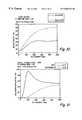
- FIG. 6is a plot of polarization ratio as a function of fly height for five different SiN thicknesses on the surface of an aluminum coated test disc.
- FIG. 7is a plot of polarization ratio as a function of fly height for different numerical apertures of the objective lens.
- FIG. 8is a plot of percent reflectivity as a function of fly height for five different SiN thicknesses on a glass test disc.
- FIG. 9is a plot of percent reflectivity as a function of fly height for five different numerical apertures of the objective lens.
- FIG. 10is a plot of reflectivity as a function of fly height with and without a 50% stop.
- FIG. 11is a plot of polarization ratio as function of fly height with a 50% stop for two different thicknesses of SiN on the test disc.
- FIG. 12is a plot of polarization difference as a function of fly height for a disc having an optical stack of magneto-optical material.
- FIG. 13is a plot of percent reflectance, polarization ratio and polarization sum as a function of fly height obtained with a disc having an optical stack of magneto-optical material.
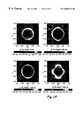
- FIG. 14is a two dimensional plot of intensity of the x-polarized component of reflected light obtained following reflection of an x-polarized incident field for four different fly heights above an aluminum coated disc: a) 0 nm fly height, b) 100 nm fly height, c) 200 nm fly height, and d) 400 nm fly height.
- FIG. 15is a two dimensional plot of phase of the x-polarized component of reflected light obtained following reflection of an x-polarized incident field for four different fly heights above an aluminum coated disc: a) 0 nm fly height, b) 100 nm fly height, c) 200 nm fly height, and d) 400 nm fly height.
- a slider with an objective lenscan be used to obtain the distance, i.e. fly height, from the slider to a spinning disc. Only a single source of monochromatic or quasi-monochromatic light is needed. The distance between the slider and the disc is held approximately constant to make the measurement.
- Light propagating from the discis directed to a detector. For example, light reflected from the disc back through the objective lens can be directed by a beam splitter to a detector. Alternatively, the light transmitted through the disc can be directed to a detector.
- the detectormeasures one or more properties of the reflected (transmitted) light. Suitable properties for obtaining the distance measurement include polarization, intensity distribution and/or phase distribution, for example. The properties are correlated with distance properties such that using subsequent measurements a microprocessor can monitor the detector output and provide an output related to fly height.
- Particularly suitable optical recording headsinclude near-field optical recording heads.
- Near-field optical recording headshave a fly height generally on the order of a wavelength of light or less.
- the optics mounted on the sliderare coupled to the surface of the disc through evanescent coupling due to the small separation.
- the slider opticsgenerally include an objective lens that focuses the light onto, or slightly below, the bottom surface of the slider.
- the slider optics on near-field recording headsgenerally also include a Solid Immersion Lens (SIL) or the like to reduce spot size.
- SILSolid Immersion Lens
- an embodiment of a measurement system to measure light reflected from the discincludes a light source 100 , a beam splitter 102 , a slider 104 , a detector module 106 and processor 108 .
- the measurement systemis positioned relative to a disc spinning system with slider 104 near the surface 110 of a disc 112 when the disc is in position.
- the disc spinning systemincludes a motor 114 such as a spindle motor for spinning disc 112 .
- the measurement systemoptionally can include a power meter 116 positioned to receive a portion of the incident light from source 100 reflected by beam splitter 102 .
- the measurement systemis configured to measure light transmitted through the disc 112 .
- beam splitter 102can be removed or replaced with a polarizer. Additional optical elements, such as mirrors and lenses, can be used to direct the transmitted light to the detector as desired.
- Light source 100generally outputs monochromatic or quasi-monochromatic light along light path 118 .
- Suitable light sourcesinclude a mercury arc lamp, a light emitting diode, a diode laser and the like.
- Light path 118passes through beam splitter 102 .
- Transmitted lightfollows split light path 120 .
- a partial polarizing beam splittercan be used if the detection system is sensitive to polarized light. Even if the light source 100 is polarized, a polarizing beam splitter can be used to increase the polarization ratio, for example, if the polarization-ratio (I p to I s ) of the source is relatively low, such as a laser diode with a polarization ratio of about 100 to 1.
- transmitted light along split light path 120is partially plane polarized.
- Light with partially orthogonal polarizationis reflected at 90 degrees relative to the incident direction.
- the reflected incident lightis directed to power meter 116 , if desired.
- slider 104generally is at the end of arm 122 , which can be a flexure spring suspension arm.
- Slider 104includes an objective lens 124 .
- Objective lens 124can be mounted on slider base 126 using spacers 128 .
- Slider 104optionally includes slider optics 130 .
- Slider optics 130help to optically couple objective lens 124 with the surface of disc 110 to minimize distortions due to changing index of refraction.
- Suitable slider optics 130include Solid Immersion Lenses (SILs) or the like. Preferred sliders are part of near-field optical recording heads.
- Objective lens 124is placed within split light path 120 and creates a focused light path 132 .
- light passing through the optical elements of slider 104reflects from surface 110 of disc 112 .
- the reflected lightis passed back through the optical elements of slider 104 including objective lens 124 .
- the reflected lightcontinues to beam splitter 102 .
- a portion of the reflected lightis directed at a 90 degree angle along detection path 140 , as shown in FIG. 1 A.
- Detection path 140intersects detector module 106 .
- transmitted light path 142is directed to detector 106 .
- Disc 112generally is a test disc specifically designed for the distance measurement.
- the surface characteristicscan be selected based on the properties of the detector module 106 and the corresponding type of measurement.
- surface 110 of disc 112can be transparent or reflecting.
- surface 110 of disc 112can have a coating, if appropriate.
- a pre-embossed mediasuch as those with pits and grooves can be used, if desired.
- a portion of a data storage disccan have a specific portion reserved for use as a test disc.
- disc 112is a reflecting, aluminum coated disc.
- the aluminum coated disccan optionally include a thin layer of an optically transparent material such as SiN.
- the thin filmgenerally would have a thickness on the order of a wavelength or less.
- the thickness of the SiN layeralters the properties of the reflected light.
- the air-incident surface of the SiNcan be coated with a lubricant.
- disc 112includes a glass disc, with or without a thin-film layer such as SiN.
- reflectivityis a particularly suitable measurement for determining fly height.
- a third embodiment of test disc 112is a glass or aluminum coated disc with an optical stack containing magneto-optical (MO) media.
- Detector module 106can include elements to measure one or more of these distance dependent properties and provide an output to processor 108 , for example, by way of cable 144 . If necessary, a analog-to-digital converter or other signal conditioners can be included to prepare the signal for processor 108 .
- the selection of a suitable detection approach and test discmay be based on the acceptable tolerances in fly height and the ranges of expected deviation from acceptable values of fly height.
- the discis spun at a fixed speed. After a brief transient period, the slider obtains a relatively constant height above the disc surface. The measurements then are performed. The optical head is aligned with the light path by maximizing the light reflected back into the detector module. In general, the output of detector modules set forth herein are correlated to fly height. Using an alternative fly height measurement technique, the correlation is obtained, which can be stored in memory 146 of processor 108 .
- a first embodiment of detector module 106includes an optional slit aperture 150 , a lens 152 , an optional iris diaphragm 154 and a two element detector 156 .
- Slit aperture 150can reduce noise.
- Lens 152focuses light onto detector 156 .
- Optional iris diaphragm 154can be placed either before or after lens 152 in the light path.
- iris diaphragm 154is placed after lens 152 between lens 152 and two element detector 156 .
- Iris diaphragm 154can be used as a central aperture stop such as a half aperture (50%) stop. Iris diaphragm 154 generally reduces the contribution of reflected light near normal incidence with respect to the disc surface to enhance the contribution of light waves having higher angles of incidence.
- Two element detector 154has light sensitive elements 158 (A), 160 (B).
- the focus signalcan be correlated with the distance of the disc 110 to slider 104 .
- detector module 106includes a central aperture stop 170 such as an iris diaphragm, an optional waveplate 172 , a polarization beam splitter 174 , and light sensitive elements 176 (C) 178 (D).
- a central aperture stop 170such as an iris diaphragm
- an optional waveplate 172such as an optional waveplate 172
- a polarization beam splitter 174such as an optional waveplate 172
- Dlight sensitive elements 176 (C) 178 (D).
- Different polarizationsgenerally reflect differently from the surface of disc 110 .
- the difference in reflectivitygenerally depends on the distance between slider 104 and disc 110 .
- This configuration of detector module 106also can be used to obtain a value proportional to the total amount of reflected light by adding the measurements of elements 176 , 178 (C+D).
- Waveplate 172can be used to alter the polarization of the light following path 140 prior to striking polarization beam splitter 174 .
- the waveplatecan be a half waveplate placed at 22.5 degrees or a quarter waveplate placed at 45 degrees.
- polarization ratio as a function of fly heightwas evaluated with an aluminum coated test disc using a experimental arrangement shown schematically in FIG. 1 A.
- the polarization ratiois defined as the ratio of y-polarized light to x-polarized light in the reflected beam when the incident light is purely x-polarized.
- the objective lenshad a numerical aperture of 0.65, and the SIL had a numerical aperture of 2.15.
- the RIM intensity at the objective lenswas 0.28.
- the effect of SiN thickness on the aluminum coated discalso was evaluated with respect to the polarization ratio (PR) as a function of fly height.
- PRpolarization ratio
- Different SiN thicknessesproduce PR curves as functions of fly height with different effective ranges corresponding to regions over which the curve changes monotonically.
- this correlationcan be-stored and used in subsequent fly height measurements.
- fly heightcan be measured over a 500 nm range with good accuracy without requiring monotonic curves for a particular SiN thickness over the effective range.
- FIG. 7measurements obtained with different numerical apertures of the objective lens demonstrate that the technique accommodates a wide range of numerical apertures.
- Measurement of percent reflectivity as a function of fly heightare plotted in FIG. 8 for five different thicknesses of SiN.
- the reflectivitywas measured relative to the measurement of a power meter corresponding to element 114 of FIG. 1 .
- the reflectivity curvehas a monotonic range of about 250 nm for the particular numerical aperture of the objective lens.
- the effective range of the reflectivity measurementsis a mild function of numerical aperture since the fly height at the first maximum of the reflectivity does not change significantly for different values of numerical aperture.
- the measurement rangecan be improved significantly with the addition of a central aperture stop either in the incident beam or in the reflected beam prior to the detectors, as shown in FIG. 3 .
- the effect of a 50% stop on a reflectivity measurementcan be seen in FIG. 10 .
- the lens for these measurementsdid not have a SiN coating.
- the 50% stopcorresponds to a pupil radius of 0.707 relative to a maximum clear aperture radius of 1.0. With a numerical aperture of 0.65, the 50% stop increases the effective range to about 500 nm.
- the polarization ratio as a function of fly heightwas obtained with a 50% stop for two aluminum coated discs having different SiN thicknesses. The 50% stop greatly enhanced the sensitivity of the polarization ratio measurements.
- FIG. 12measurements of polarization differences were made as a function of fly height with a disc coated with an optical stack containing MO media. Similar measurements of percent reflectivity (REF), percent sum, and polarization ratio are presented in FIG. 13 . “Reflectivity” is the total intensity of the beam returning through the lens, while “sum” is the is the total intensity measured after reflection from a partially polarizing beam splitter. These measurements were made with a 50% stop in the reflected beam. All of the measurements shown in FIGS. 14 and 15 show good characteristics indicating their suitableness for measurements up to about 500 nm fly height.
- detector module 106includes an optional slit aperture 190 , a polarizer 192 and a detector array 194 .
- This embodimentcan also include an iris diaphragm.
- Polarizer 192preferably is oriented at 0, 45 or 90 degrees relative to the initial polarization depending on the measurement desired. The polarizer is rotated between the preferred values or other values to measure the intensity distribution for different polarization states. Similar information can be obtained from a measurement with the polarizer and a second measurement without the polarizer.
- Detector array 194can be a CCD array or any other light sensitive array or appropriate dimensions. Detector array 194 can have a one dimensional array or a two dimensional array of light sensitive elements. The intensity pattern measured with detector array 194 will reflect the distance between slider 104 and disc 112 .
- FIG. 14depicts intensity distribution of the x-polarized field component of the reflected beam obtained with an aluminum coated test disc and x-polarized incident light. The measurements may be made using an array detector. The intensity distribution is shown for four fly heights.
- FIG. 15depicts the phase distribution of the x-polarized field component of the reflected beam for four fly heights. Since the intensity distribution and phase distribution vary with fly height these can be used to calculate fly height. In the case of the phase distributions, measurements based on the focus sensor of the detector module in FIG. 3 are particularly suitable measurements for the calculation of fly height.
- lightor “optical” refers to radiation of any wavelength and are not limited to visible radiation.
Landscapes
- Physics & Mathematics (AREA)
- Optics & Photonics (AREA)
- General Physics & Mathematics (AREA)
- Length Measuring Devices By Optical Means (AREA)
Abstract
Description
Claims (19)
Priority Applications (1)
| Application Number | Priority Date | Filing Date | Title |
|---|---|---|---|
| US09/155,460US6688743B1 (en) | 1998-02-17 | 1998-09-29 | Method and apparatus to determine fly height of a recording head |
Applications Claiming Priority (3)
| Application Number | Priority Date | Filing Date | Title |
|---|---|---|---|
| US7496698P | 1998-02-17 | 1998-02-17 | |
| PCT/US1998/020311WO1999041566A1 (en) | 1998-02-17 | 1998-09-29 | Method and apparatus to determine fly height of a recording head |
| US09/155,460US6688743B1 (en) | 1998-02-17 | 1998-09-29 | Method and apparatus to determine fly height of a recording head |
Publications (1)
| Publication Number | Publication Date |
|---|---|
| US6688743B1true US6688743B1 (en) | 2004-02-10 |
Family
ID=30772402
Family Applications (1)
| Application Number | Title | Priority Date | Filing Date |
|---|---|---|---|
| US09/155,460Expired - LifetimeUS6688743B1 (en) | 1998-02-17 | 1998-09-29 | Method and apparatus to determine fly height of a recording head |
Country Status (1)
| Country | Link |
|---|---|
| US (1) | US6688743B1 (en) |
Cited By (6)
| Publication number | Priority date | Publication date | Assignee | Title |
|---|---|---|---|---|
| US20040261684A1 (en)* | 2003-06-26 | 2004-12-30 | Tige Boats, Inc | Boat with wake control |
| US20070286031A1 (en)* | 2006-06-12 | 2007-12-13 | Takuya Matsumoto | Optical Near-Field Generator and Recording and Reproduction Apparatus |
| US20080151408A1 (en)* | 2006-12-22 | 2008-06-26 | Soo-Choon Kang | Iteration method to improve the fly height measurement accuracy by optical interference method and theoretical pitch and roll effect |
| US20090040531A1 (en)* | 2007-08-07 | 2009-02-12 | Seagate Technology Llc | Optical Fly Height Measurement |
| US20090113464A1 (en)* | 2007-10-29 | 2009-04-30 | Seagate Technology Llc | Fly Height And Slider Protrusion Measurement |
| US9982991B2 (en) | 2014-08-29 | 2018-05-29 | Asml Netherlands B.V. | Method for controlling a distance between two objects, inspection apparatus and method |
Citations (31)
| Publication number | Priority date | Publication date | Assignee | Title |
|---|---|---|---|---|
| US3980811A (en) | 1974-09-03 | 1976-09-14 | Nihon Denshi Kabushiki Kaisha | Contacting pickup optical reproduction system |
| US4229067A (en) | 1978-11-17 | 1980-10-21 | Corning Glass Works | Optical waveguide mode scrambler |
| US4310916A (en) | 1979-09-27 | 1982-01-12 | U.S. Philips Corporation | Optical record carrier and apparatus for reading it |
| US4443700A (en) | 1980-02-01 | 1984-04-17 | Pedro B. Macedo | Optical sensing apparatus and method |
| US4569038A (en) | 1980-12-19 | 1986-02-04 | Matsushita Electric Industrial Co., Ltd. | Optical disk, high density optical disk system, and high density recording/reproducing method using the optical disk |
| US4581529A (en) | 1983-08-15 | 1986-04-08 | At&T Bell Laboratories | Read/write system for optical disc apparatus with fiber optics |
| US4706235A (en) | 1985-01-25 | 1987-11-10 | Storage Technology Partners 11 | Differential track recording |
| US4769800A (en) | 1985-08-27 | 1988-09-06 | Siemens Aktiengesellschaft | Positioning device for a sensing head of an optical data storage system |
| US4801794A (en)* | 1984-05-29 | 1989-01-31 | Xerox Corporation | Data detection and optical focus error detection system for rotating optical media |
| US4933537A (en) | 1986-01-16 | 1990-06-12 | Csk Corporation | Apparatus for controlling movement of an optical memory card for data transfer therewith |
| US5004307A (en) | 1990-04-12 | 1991-04-02 | The Board Of Trustees Of The Leland Stanford Junior University | Near field and solid immersion optical microscope |
| US5096277A (en) | 1982-08-06 | 1992-03-17 | Kleinerman Marcos Y | Remote measurement of physical variables with fiber optic systems |
| US5125750A (en) | 1991-03-14 | 1992-06-30 | The Board Of Trustees Of The Leland Stanford Junior University | Optical recording system employing a solid immersion lens |
| US5138676A (en) | 1990-06-15 | 1992-08-11 | Aster Corporation | Miniature fiberoptic bend device and method |
| US5153870A (en) | 1989-06-29 | 1992-10-06 | Digital Equipment Corporation | Rotary head actuator for optical disk |
| US5193132A (en) | 1989-05-02 | 1993-03-09 | Raynet Corporation | Method of coupling light via a coupler on a fiber optic light guide using phase space matching |
| US5212379A (en) | 1991-12-06 | 1993-05-18 | Alamed Corporation | Fiber optical monitor for detecting motion based on changes in speckle patterns |
| US5278812A (en) | 1992-02-18 | 1994-01-11 | At&T Bell Laboratories | Tracking and focussing functions in optical disk apparatus |
| US5280340A (en) | 1991-10-23 | 1994-01-18 | Phase Metrics | Method and apparatus to calibrate intensity and determine fringe order for interferometric measurement of small spacings |
| US5286971A (en) | 1990-11-19 | 1994-02-15 | At&T Bell Laboratories | Data recording using a near field optical probe |
| US5363463A (en) | 1982-08-06 | 1994-11-08 | Kleinerman Marcos Y | Remote sensing of physical variables with fiber optic systems |
| US5424834A (en)* | 1992-06-19 | 1995-06-13 | Agency Of Industrial Science & Technology, Ministry Of International Trade & Industry | Optical displacement sensor for measurement of shape and coarseness of a target workpiece surface |
| US5450203A (en) | 1993-12-22 | 1995-09-12 | Electroglas, Inc. | Method and apparatus for determining an objects position, topography and for imaging |
| US5457534A (en) | 1991-10-23 | 1995-10-10 | Phase Metrics | Method and apparatus to calibrate intensity and determine fringe order for interferometric measurement of small spacings |
| US5493393A (en) | 1989-03-17 | 1996-02-20 | The Boeing Company | Planar waveguide spectrograph |
| US5497359A (en) | 1994-08-30 | 1996-03-05 | National Business Machines Corporation | Optical disk data storage system with radiation-transparent air-bearing slider |
| US5535189A (en) | 1992-04-10 | 1996-07-09 | Alon; Amir | Optical information system with a broad non-coherent irradiating beam coupled with optical fiber from a laser source |
| US5557597A (en)* | 1994-07-30 | 1996-09-17 | Samsung Electronics Co., Ltd. | Focus error detector |
| US5566159A (en) | 1993-10-04 | 1996-10-15 | Zen Research N.V. | Optical disk reader |
| US5592444A (en) | 1993-06-14 | 1997-01-07 | Zen Research N.V. | Method of writing data simultaneously on a plurality of tracks of an optical disk, and apparatus therefor |
| US6307627B1 (en)* | 1997-09-22 | 2001-10-23 | Hdi Instrumentation | Optical measurement system using polarized light |
- 1998
- 1998-09-29USUS09/155,460patent/US6688743B1/ennot_activeExpired - Lifetime
Patent Citations (37)
| Publication number | Priority date | Publication date | Assignee | Title |
|---|---|---|---|---|
| US3980811A (en) | 1974-09-03 | 1976-09-14 | Nihon Denshi Kabushiki Kaisha | Contacting pickup optical reproduction system |
| US4229067A (en) | 1978-11-17 | 1980-10-21 | Corning Glass Works | Optical waveguide mode scrambler |
| US4310916A (en) | 1979-09-27 | 1982-01-12 | U.S. Philips Corporation | Optical record carrier and apparatus for reading it |
| US4443700A (en) | 1980-02-01 | 1984-04-17 | Pedro B. Macedo | Optical sensing apparatus and method |
| US4569038A (en) | 1980-12-19 | 1986-02-04 | Matsushita Electric Industrial Co., Ltd. | Optical disk, high density optical disk system, and high density recording/reproducing method using the optical disk |
| US5363463A (en) | 1982-08-06 | 1994-11-08 | Kleinerman Marcos Y | Remote sensing of physical variables with fiber optic systems |
| US5096277A (en) | 1982-08-06 | 1992-03-17 | Kleinerman Marcos Y | Remote measurement of physical variables with fiber optic systems |
| US4581529A (en) | 1983-08-15 | 1986-04-08 | At&T Bell Laboratories | Read/write system for optical disc apparatus with fiber optics |
| US4801794A (en)* | 1984-05-29 | 1989-01-31 | Xerox Corporation | Data detection and optical focus error detection system for rotating optical media |
| US4706235A (en) | 1985-01-25 | 1987-11-10 | Storage Technology Partners 11 | Differential track recording |
| US4815064A (en) | 1985-01-25 | 1989-03-21 | Storage Technology Partners Ii | Differential track recording |
| US4769800A (en) | 1985-08-27 | 1988-09-06 | Siemens Aktiengesellschaft | Positioning device for a sensing head of an optical data storage system |
| US4933537A (en) | 1986-01-16 | 1990-06-12 | Csk Corporation | Apparatus for controlling movement of an optical memory card for data transfer therewith |
| US4994658A (en) | 1986-01-16 | 1991-02-19 | Csk Corporation | Apparatus for controlling movement of an optical memory card for data transfer therewith |
| US5493393A (en) | 1989-03-17 | 1996-02-20 | The Boeing Company | Planar waveguide spectrograph |
| US5193132A (en) | 1989-05-02 | 1993-03-09 | Raynet Corporation | Method of coupling light via a coupler on a fiber optic light guide using phase space matching |
| US5153870A (en) | 1989-06-29 | 1992-10-06 | Digital Equipment Corporation | Rotary head actuator for optical disk |
| US5004307A (en) | 1990-04-12 | 1991-04-02 | The Board Of Trustees Of The Leland Stanford Junior University | Near field and solid immersion optical microscope |
| US5138676A (en) | 1990-06-15 | 1992-08-11 | Aster Corporation | Miniature fiberoptic bend device and method |
| US5286971A (en) | 1990-11-19 | 1994-02-15 | At&T Bell Laboratories | Data recording using a near field optical probe |
| US5125750A (en) | 1991-03-14 | 1992-06-30 | The Board Of Trustees Of The Leland Stanford Junior University | Optical recording system employing a solid immersion lens |
| US5457534A (en) | 1991-10-23 | 1995-10-10 | Phase Metrics | Method and apparatus to calibrate intensity and determine fringe order for interferometric measurement of small spacings |
| US5486924A (en)* | 1991-10-23 | 1996-01-23 | Phase Metrics | Method and apparatus for measurement of roughness and hardness of a surface |
| US5280340A (en) | 1991-10-23 | 1994-01-18 | Phase Metrics | Method and apparatus to calibrate intensity and determine fringe order for interferometric measurement of small spacings |
| US5212379A (en) | 1991-12-06 | 1993-05-18 | Alamed Corporation | Fiber optical monitor for detecting motion based on changes in speckle patterns |
| US5278812A (en) | 1992-02-18 | 1994-01-11 | At&T Bell Laboratories | Tracking and focussing functions in optical disk apparatus |
| US5598393A (en) | 1992-04-10 | 1997-01-28 | Zen Research N.V. | Method and apparatus for reading data |
| US5535189A (en) | 1992-04-10 | 1996-07-09 | Alon; Amir | Optical information system with a broad non-coherent irradiating beam coupled with optical fiber from a laser source |
| US5537385A (en) | 1992-04-10 | 1996-07-16 | Alon; Amir | Reading multiple tracks data with a microscope scanner and a two mirror light beam focus unit |
| US5574712A (en) | 1992-04-10 | 1996-11-12 | Zen Research N.V. | Detector matrix for acquiring track data from multiple tracks |
| US5424834A (en)* | 1992-06-19 | 1995-06-13 | Agency Of Industrial Science & Technology, Ministry Of International Trade & Industry | Optical displacement sensor for measurement of shape and coarseness of a target workpiece surface |
| US5592444A (en) | 1993-06-14 | 1997-01-07 | Zen Research N.V. | Method of writing data simultaneously on a plurality of tracks of an optical disk, and apparatus therefor |
| US5566159A (en) | 1993-10-04 | 1996-10-15 | Zen Research N.V. | Optical disk reader |
| US5450203A (en) | 1993-12-22 | 1995-09-12 | Electroglas, Inc. | Method and apparatus for determining an objects position, topography and for imaging |
| US5557597A (en)* | 1994-07-30 | 1996-09-17 | Samsung Electronics Co., Ltd. | Focus error detector |
| US5497359A (en) | 1994-08-30 | 1996-03-05 | National Business Machines Corporation | Optical disk data storage system with radiation-transparent air-bearing slider |
| US6307627B1 (en)* | 1997-09-22 | 2001-10-23 | Hdi Instrumentation | Optical measurement system using polarized light |
Cited By (13)
| Publication number | Priority date | Publication date | Assignee | Title |
|---|---|---|---|---|
| US6874441B2 (en)* | 2003-06-26 | 2005-04-05 | Tige Boats, Inc. | Boat with wake control |
| US20040261684A1 (en)* | 2003-06-26 | 2004-12-30 | Tige Boats, Inc | Boat with wake control |
| US7652775B2 (en)* | 2006-06-12 | 2010-01-26 | Hitachi, Ltd. | Optical near-field generator and recording and reproduction apparatus |
| US20070286031A1 (en)* | 2006-06-12 | 2007-12-13 | Takuya Matsumoto | Optical Near-Field Generator and Recording and Reproduction Apparatus |
| US20080151408A1 (en)* | 2006-12-22 | 2008-06-26 | Soo-Choon Kang | Iteration method to improve the fly height measurement accuracy by optical interference method and theoretical pitch and roll effect |
| US7817286B2 (en) | 2006-12-22 | 2010-10-19 | Hitachi Global Storage Technologies Netherlands B.V. | Iteration method to improve the fly height measurement accuracy by optical interference method and theoretical pitch and roll effect |
| US20090040531A1 (en)* | 2007-08-07 | 2009-02-12 | Seagate Technology Llc | Optical Fly Height Measurement |
| US7768657B2 (en) | 2007-08-07 | 2010-08-03 | Seagate Technology Llc | Optical fly height measurement |
| US20090113464A1 (en)* | 2007-10-29 | 2009-04-30 | Seagate Technology Llc | Fly Height And Slider Protrusion Measurement |
| US8098381B2 (en)* | 2007-10-29 | 2012-01-17 | Seagate Technology Llc | Fly height and slider protrusion measurement |
| TWI401674B (en)* | 2007-10-29 | 2013-07-11 | Seagate Technology Llc | Apparatus and system for fly height and slider protrusion measurement |
| KR101331997B1 (en)* | 2007-10-29 | 2013-11-25 | 시게이트 테크놀로지 엘엘씨 | An apparatus and system for measuring a distance or fly height |
| US9982991B2 (en) | 2014-08-29 | 2018-05-29 | Asml Netherlands B.V. | Method for controlling a distance between two objects, inspection apparatus and method |
Similar Documents
| Publication | Publication Date | Title |
|---|---|---|
| US8009545B2 (en) | Optical recording using a waveguide structure and a phase change medium | |
| US5245174A (en) | Focus sensing apparatus utilizing a reflecting surface having variable reflectivity | |
| US5717682A (en) | Optical disk having information pits of different lengths and shapes | |
| US6751044B1 (en) | Method and apparatus for reading a clock track with a magneto-optical clock head using the transverse Kerr effect | |
| GB2248989A (en) | Focus detection | |
| US6688743B1 (en) | Method and apparatus to determine fly height of a recording head | |
| WO1999041566A1 (en) | Method and apparatus to determine fly height of a recording head | |
| CN1074570C (en) | Optical pickup device | |
| US5932887A (en) | Apparatus for measuring the flying height and orientation of a magnetic head relative to a transparent medium based on frustrated total internal reflection | |
| JP2009500776A (en) | Optical pickup and / or recording device | |
| JP3441670B2 (en) | Lens inspection system and lens inspection device | |
| JP2003247934A (en) | Birefringence measurement method and birefringence measurement device | |
| JPH09115177A (en) | Optical pickup system | |
| US6462349B1 (en) | Measuring spacing between two surfaces via evanescent coupling | |
| JPH04229427A (en) | Optical position-error detecting system | |
| US5677805A (en) | Apparatus for determining the dynamic position and orientation of a transducing head relative to a storage medium | |
| US20040196469A1 (en) | Optical profiler for ultra-smooth surface with normal incident beam deflection method | |
| US6847459B2 (en) | Method and apparatus for dynamically measuring the full flying state of a slider | |
| US5400306A (en) | Differential detection assembly for data retrieval from a data storage disk | |
| JPH11232768A (en) | Method and device for discriminating disk | |
| KR100476318B1 (en) | Optical distance measuring apparatus and optical pickup device using the same | |
| KR100474384B1 (en) | Internal reflection type distance measuring apparatus and optical pickup device using the same | |
| KR20030035901A (en) | Optical disk device and recording/reproducing method | |
| JPS637950Y2 (en) | ||
| JPS58137141A (en) | Focus detecting method |
Legal Events
| Date | Code | Title | Description |
|---|---|---|---|
| AS | Assignment | Owner name:SEAGATE TECHNOLOGY INC., CALIFORNIA Free format text:ASSIGNMENT OF ASSIGNORS INTEREST;ASSIGNORS:DURNIN, JAMES E.;GAGE, EDWARD C.;MOWRY, GREGORY S.;REEL/FRAME:010296/0127;SIGNING DATES FROM 19980918 TO 19980923 | |
| AS | Assignment | Owner name:SEAGATE TECHNOLOGY LLC, CALIFORNIA Free format text:ASSIGNMENT OF ASSIGNORS INTEREST;ASSIGNOR:SEAGATE TECHNOLOGY, INC.;REEL/FRAME:010962/0954 Effective date:20000628 | |
| AS | Assignment | Owner name:JPMORGAN CHASE BANK, AS COLLATERAL AGENT, NEW YORK Free format text:SECURITY AGREEMENT;ASSIGNOR:SEAGATE TECHNOLOGY LLC;REEL/FRAME:013177/0001 Effective date:20020513 Owner name:JPMORGAN CHASE BANK, AS COLLATERAL AGENT,NEW YORK Free format text:SECURITY AGREEMENT;ASSIGNOR:SEAGATE TECHNOLOGY LLC;REEL/FRAME:013177/0001 Effective date:20020513 | |
| STCF | Information on status: patent grant | Free format text:PATENTED CASE | |
| AS | Assignment | Owner name:SEAGATE TECHNOLOGY LLC, CALIFORNIA Free format text:RELEASE OF SECURITY INTERESTS IN PATENT RIGHTS;ASSIGNOR:JPMORGAN CHASE BANK, N.A. (FORMERLY KNOWN AS THE CHASE MANHATTAN BANK AND JPMORGAN CHASE BANK), AS ADMINISTRATIVE AGENT;REEL/FRAME:016958/0607 Effective date:20051130 | |
| FPAY | Fee payment | Year of fee payment:4 | |
| CC | Certificate of correction | ||
| AS | Assignment | Owner name:WELLS FARGO BANK, NATIONAL ASSOCIATION, AS COLLATERAL AGENT AND SECOND PRIORITY REPRESENTATIVE, CALIFORNIA Free format text:SECURITY AGREEMENT;ASSIGNORS:MAXTOR CORPORATION;SEAGATE TECHNOLOGY LLC;SEAGATE TECHNOLOGY INTERNATIONAL;REEL/FRAME:022757/0017 Effective date:20090507 Owner name:JPMORGAN CHASE BANK, N.A., AS ADMINISTRATIVE AGENT AND FIRST PRIORITY REPRESENTATIVE, NEW YORK Free format text:SECURITY AGREEMENT;ASSIGNORS:MAXTOR CORPORATION;SEAGATE TECHNOLOGY LLC;SEAGATE TECHNOLOGY INTERNATIONAL;REEL/FRAME:022757/0017 Effective date:20090507 Owner name:JPMORGAN CHASE BANK, N.A., AS ADMINISTRATIVE AGENT Free format text:SECURITY AGREEMENT;ASSIGNORS:MAXTOR CORPORATION;SEAGATE TECHNOLOGY LLC;SEAGATE TECHNOLOGY INTERNATIONAL;REEL/FRAME:022757/0017 Effective date:20090507 Owner name:WELLS FARGO BANK, NATIONAL ASSOCIATION, AS COLLATE Free format text:SECURITY AGREEMENT;ASSIGNORS:MAXTOR CORPORATION;SEAGATE TECHNOLOGY LLC;SEAGATE TECHNOLOGY INTERNATIONAL;REEL/FRAME:022757/0017 Effective date:20090507 | |
| AS | Assignment | Owner name:SEAGATE TECHNOLOGY INTERNATIONAL, CALIFORNIA Free format text:RELEASE;ASSIGNOR:JPMORGAN CHASE BANK, N.A., AS ADMINISTRATIVE AGENT;REEL/FRAME:025662/0001 Effective date:20110114 Owner name:MAXTOR CORPORATION, CALIFORNIA Free format text:RELEASE;ASSIGNOR:JPMORGAN CHASE BANK, N.A., AS ADMINISTRATIVE AGENT;REEL/FRAME:025662/0001 Effective date:20110114 Owner name:SEAGATE TECHNOLOGY HDD HOLDINGS, CALIFORNIA Free format text:RELEASE;ASSIGNOR:JPMORGAN CHASE BANK, N.A., AS ADMINISTRATIVE AGENT;REEL/FRAME:025662/0001 Effective date:20110114 Owner name:SEAGATE TECHNOLOGY LLC, CALIFORNIA Free format text:RELEASE;ASSIGNOR:JPMORGAN CHASE BANK, N.A., AS ADMINISTRATIVE AGENT;REEL/FRAME:025662/0001 Effective date:20110114 | |
| AS | Assignment | Owner name:THE BANK OF NOVA SCOTIA, AS ADMINISTRATIVE AGENT, CANADA Free format text:SECURITY AGREEMENT;ASSIGNOR:SEAGATE TECHNOLOGY LLC;REEL/FRAME:026010/0350 Effective date:20110118 Owner name:THE BANK OF NOVA SCOTIA, AS ADMINISTRATIVE AGENT, Free format text:SECURITY AGREEMENT;ASSIGNOR:SEAGATE TECHNOLOGY LLC;REEL/FRAME:026010/0350 Effective date:20110118 | |
| FPAY | Fee payment | Year of fee payment:8 | |
| AS | Assignment | Owner name:SEAGATE TECHNOLOGY LLC, CALIFORNIA Free format text:TERMINATION AND RELEASE OF SECURITY INTEREST IN PATENT RIGHTS;ASSIGNOR:WELLS FARGO BANK, NATIONAL ASSOCIATION, AS COLLATERAL AGENT AND SECOND PRIORITY REPRESENTATIVE;REEL/FRAME:030833/0001 Effective date:20130312 Owner name:EVAULT INC. (F/K/A I365 INC.), CALIFORNIA Free format text:TERMINATION AND RELEASE OF SECURITY INTEREST IN PATENT RIGHTS;ASSIGNOR:WELLS FARGO BANK, NATIONAL ASSOCIATION, AS COLLATERAL AGENT AND SECOND PRIORITY REPRESENTATIVE;REEL/FRAME:030833/0001 Effective date:20130312 Owner name:SEAGATE TECHNOLOGY US HOLDINGS, INC., CALIFORNIA Free format text:TERMINATION AND RELEASE OF SECURITY INTEREST IN PATENT RIGHTS;ASSIGNOR:WELLS FARGO BANK, NATIONAL ASSOCIATION, AS COLLATERAL AGENT AND SECOND PRIORITY REPRESENTATIVE;REEL/FRAME:030833/0001 Effective date:20130312 Owner name:SEAGATE TECHNOLOGY INTERNATIONAL, CAYMAN ISLANDS Free format text:TERMINATION AND RELEASE OF SECURITY INTEREST IN PATENT RIGHTS;ASSIGNOR:WELLS FARGO BANK, NATIONAL ASSOCIATION, AS COLLATERAL AGENT AND SECOND PRIORITY REPRESENTATIVE;REEL/FRAME:030833/0001 Effective date:20130312 | |
| FPAY | Fee payment | Year of fee payment:12 | |
| AS | Assignment | Owner name:SEAGATE TECHNOLOGY PUBLIC LIMITED COMPANY, CALIFORNIA Free format text:RELEASE BY SECURED PARTY;ASSIGNOR:THE BANK OF NOVA SCOTIA;REEL/FRAME:072193/0001 Effective date:20250303 Owner name:SEAGATE TECHNOLOGY, CALIFORNIA Free format text:RELEASE BY SECURED PARTY;ASSIGNOR:THE BANK OF NOVA SCOTIA;REEL/FRAME:072193/0001 Effective date:20250303 Owner name:SEAGATE TECHNOLOGY HDD HOLDINGS, CALIFORNIA Free format text:RELEASE BY SECURED PARTY;ASSIGNOR:THE BANK OF NOVA SCOTIA;REEL/FRAME:072193/0001 Effective date:20250303 Owner name:I365 INC., CALIFORNIA Free format text:RELEASE BY SECURED PARTY;ASSIGNOR:THE BANK OF NOVA SCOTIA;REEL/FRAME:072193/0001 Effective date:20250303 Owner name:SEAGATE TECHNOLOGY LLC, CALIFORNIA Free format text:RELEASE BY SECURED PARTY;ASSIGNOR:THE BANK OF NOVA SCOTIA;REEL/FRAME:072193/0001 Effective date:20250303 Owner name:SEAGATE TECHNOLOGY INTERNATIONAL, CAYMAN ISLANDS Free format text:RELEASE BY SECURED PARTY;ASSIGNOR:THE BANK OF NOVA SCOTIA;REEL/FRAME:072193/0001 Effective date:20250303 Owner name:SEAGATE HDD CAYMAN, CAYMAN ISLANDS Free format text:RELEASE BY SECURED PARTY;ASSIGNOR:THE BANK OF NOVA SCOTIA;REEL/FRAME:072193/0001 Effective date:20250303 Owner name:SEAGATE TECHNOLOGY (US) HOLDINGS, INC., CALIFORNIA Free format text:RELEASE BY SECURED PARTY;ASSIGNOR:THE BANK OF NOVA SCOTIA;REEL/FRAME:072193/0001 Effective date:20250303 |