US6688283B2 - Engine start strategy - Google Patents
Engine start strategyDownload PDFInfo
- Publication number
- US6688283B2 US6688283B2US09/951,286US95128601AUS6688283B2US 6688283 B2US6688283 B2US 6688283B2US 95128601 AUS95128601 AUS 95128601AUS 6688283 B2US6688283 B2US 6688283B2
- Authority
- US
- United States
- Prior art keywords
- engine
- engine speed
- target
- speed
- disable
- Prior art date
- Legal status (The legal status is an assumption and is not a legal conclusion. Google has not performed a legal analysis and makes no representation as to the accuracy of the status listed.)
- Expired - Lifetime, expires
Links
Images


Classifications
- F—MECHANICAL ENGINEERING; LIGHTING; HEATING; WEAPONS; BLASTING
- F02—COMBUSTION ENGINES; HOT-GAS OR COMBUSTION-PRODUCT ENGINE PLANTS
- F02D—CONTROLLING COMBUSTION ENGINES
- F02D41/00—Electrical control of supply of combustible mixture or its constituents
- F02D41/02—Circuit arrangements for generating control signals
- F02D41/14—Introducing closed-loop corrections
- F02D41/1401—Introducing closed-loop corrections characterised by the control or regulation method
- F02D41/1402—Adaptive control
- F—MECHANICAL ENGINEERING; LIGHTING; HEATING; WEAPONS; BLASTING
- F02—COMBUSTION ENGINES; HOT-GAS OR COMBUSTION-PRODUCT ENGINE PLANTS
- F02D—CONTROLLING COMBUSTION ENGINES
- F02D31/00—Use of speed-sensing governors to control combustion engines, not otherwise provided for
- F02D31/001—Electric control of rotation speed
- F—MECHANICAL ENGINEERING; LIGHTING; HEATING; WEAPONS; BLASTING
- F02—COMBUSTION ENGINES; HOT-GAS OR COMBUSTION-PRODUCT ENGINE PLANTS
- F02D—CONTROLLING COMBUSTION ENGINES
- F02D41/00—Electrical control of supply of combustible mixture or its constituents
- F02D41/02—Circuit arrangements for generating control signals
- F02D41/04—Introducing corrections for particular operating conditions
- F02D41/06—Introducing corrections for particular operating conditions for engine starting or warming up
- F02D41/062—Introducing corrections for particular operating conditions for engine starting or warming up for starting
- F02D41/064—Introducing corrections for particular operating conditions for engine starting or warming up for starting at cold start
- F—MECHANICAL ENGINEERING; LIGHTING; HEATING; WEAPONS; BLASTING
- F02—COMBUSTION ENGINES; HOT-GAS OR COMBUSTION-PRODUCT ENGINE PLANTS
- F02D—CONTROLLING COMBUSTION ENGINES
- F02D41/00—Electrical control of supply of combustible mixture or its constituents
- F02D41/02—Circuit arrangements for generating control signals
- F02D41/04—Introducing corrections for particular operating conditions
- F02D41/06—Introducing corrections for particular operating conditions for engine starting or warming up
- F02D41/068—Introducing corrections for particular operating conditions for engine starting or warming up for warming-up
- B—PERFORMING OPERATIONS; TRANSPORTING
- B60—VEHICLES IN GENERAL
- B60W—CONJOINT CONTROL OF VEHICLE SUB-UNITS OF DIFFERENT TYPE OR DIFFERENT FUNCTION; CONTROL SYSTEMS SPECIALLY ADAPTED FOR HYBRID VEHICLES; ROAD VEHICLE DRIVE CONTROL SYSTEMS FOR PURPOSES NOT RELATED TO THE CONTROL OF A PARTICULAR SUB-UNIT
- B60W2510/00—Input parameters relating to a particular sub-units
- B60W2510/06—Combustion engines, Gas turbines
- B60W2510/068—Engine exhaust temperature
- B—PERFORMING OPERATIONS; TRANSPORTING
- B60—VEHICLES IN GENERAL
- B60W—CONJOINT CONTROL OF VEHICLE SUB-UNITS OF DIFFERENT TYPE OR DIFFERENT FUNCTION; CONTROL SYSTEMS SPECIALLY ADAPTED FOR HYBRID VEHICLES; ROAD VEHICLE DRIVE CONTROL SYSTEMS FOR PURPOSES NOT RELATED TO THE CONTROL OF A PARTICULAR SUB-UNIT
- B60W2710/00—Output or target parameters relating to a particular sub-units
- B60W2710/06—Combustion engines, Gas turbines
- B60W2710/0644—Engine speed
- F—MECHANICAL ENGINEERING; LIGHTING; HEATING; WEAPONS; BLASTING
- F02—COMBUSTION ENGINES; HOT-GAS OR COMBUSTION-PRODUCT ENGINE PLANTS
- F02D—CONTROLLING COMBUSTION ENGINES
- F02D41/00—Electrical control of supply of combustible mixture or its constituents
- F02D41/02—Circuit arrangements for generating control signals
- F02D41/14—Introducing closed-loop corrections
- F02D41/1401—Introducing closed-loop corrections characterised by the control or regulation method
- F02D2041/141—Introducing closed-loop corrections characterised by the control or regulation method using a feed-forward control element
- F—MECHANICAL ENGINEERING; LIGHTING; HEATING; WEAPONS; BLASTING
- F02—COMBUSTION ENGINES; HOT-GAS OR COMBUSTION-PRODUCT ENGINE PLANTS
- F02D—CONTROLLING COMBUSTION ENGINES
- F02D41/00—Electrical control of supply of combustible mixture or its constituents
- F02D41/02—Circuit arrangements for generating control signals
- F02D41/14—Introducing closed-loop corrections
- F02D41/1438—Introducing closed-loop corrections using means for determining characteristics of the combustion gases; Sensors therefor
- F02D41/1444—Introducing closed-loop corrections using means for determining characteristics of the combustion gases; Sensors therefor characterised by the characteristics of the combustion gases
- F02D41/1454—Introducing closed-loop corrections using means for determining characteristics of the combustion gases; Sensors therefor characterised by the characteristics of the combustion gases the characteristics being an oxygen content or concentration or the air-fuel ratio
- F—MECHANICAL ENGINEERING; LIGHTING; HEATING; WEAPONS; BLASTING
- F16—ENGINEERING ELEMENTS AND UNITS; GENERAL MEASURES FOR PRODUCING AND MAINTAINING EFFECTIVE FUNCTIONING OF MACHINES OR INSTALLATIONS; THERMAL INSULATION IN GENERAL
- F16H—GEARING
- F16H63/00—Control outputs from the control unit to change-speed- or reversing-gearings for conveying rotary motion or to other devices than the final output mechanism
- F16H63/40—Control outputs from the control unit to change-speed- or reversing-gearings for conveying rotary motion or to other devices than the final output mechanism comprising signals other than signals for actuating the final output mechanisms
- F16H63/50—Signals to an engine or motor
Definitions
- the present inventionrelates generally to internal combustion engines in automotive vehicles and to engine start strategies for controlling the operation of the engine. More particularly, it provides a method of controlling emissions and engine operation during the period immediately following crank startup.
- Oxygen sensorsplay a large role in present day systems that control emissions. They are used to sense oxygen in the fuel/air mixture, in exhaust manifold emissions, and in emissions from catalytic converters. Through feedback control, the output of the oxygen sensors is used to adjust various parameters to achieve better engine performance, including lowered emissions. Examples of the various parameters that can be controlled through feedback control include the amount of fuel injected into the cylinders, the fuel-to-air ratio, and spark timing.
- an oxygen sensorgenerally disposed upstream of the exhaust system for sensing the oxygen level in the exhaust gas emitted from the engine.
- the oxygen sensorcan serve to provide a feedback signal to control engine operation and adjust fuel injection to the engine to achieve good engine performance.
- some conventional oxygen sensorsare required to warm up to a sufficiently high temperature before an accurate oxygen sensor reading may be obtained.
- the oxygen sensor and processing devicesinitially may not have acquired enough information to provide adequate feedback control. Therefore, for a period of time immediately following cold start up of the vehicle engine, the oxygen sensor may not be capable of providing accurate information with which the engine may be controlled to operate to achieve low hydrocarbon emissions.
- the catalyst of the catalytic convertercan be ineffective since the catalyst requires a period of time to warm up to a temperature at which the catalyst can operate effectively to burn excess hydrocarbons.
- hydrocarbon emissionsmay initially be high due to poor burning of the excess hydrocarbons due to a low temperature catalyst.
- an over abundance of fuel in the catalystmay further cool the catalyst, thereby requiring an extended period time for the catalyst to warm up to a sufficient operating temperature.
- the techniques practiced up until nowhave shown less emission reduction than desired during the start up period.
- the present inventionprovides a solution that better controls emissions during that period.
- the strategy of the inventioncontrols operation of an internal combustion engine in the time period before an oxygen sensor is warmed up sufficiently to provide reliable feedback measurements. It involves using a target speed-time (or event) goal, and then applying feedback, feedforward, and/or adaptive controls on the difference between the target and a measured engine speed.
- the target speed time (or event)can be programmed into an engine controller as a lookup table.
- the actual engine speed at each desired time or eventcan then be compared to the desired speed to obtain a difference value.
- Fueling, or any other speed control parameterscan be modified based on the difference value using feedback or feedforward routines to correct the measured value toward the target.
- the fueling or other control parameterscan also be adapted for the next start based on any corrections.
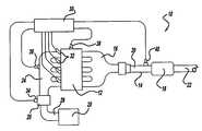
- FIG. 1is a schematic diagram of a startup control system illustrated in operational relationship with an internal combustion engine and exhaust system of an automotive vehicle.
- FIG. 2is graphic illustration of target rpm, actual measured rpm, and difference value as a function of time.
- FIG. 3is a flow diagram illustrating a methodology to control the operation of an engine during the startup period according to a preferred embodiment.
- FIG. 4is a flow diagram illustrating use of the measured engine speed to modify fuel injection to an engine according to the present invention.
- FIG. 5is a flow diagram illustrating a preferred embodiment of the invention wherein adaptive table calculations are performed to allow the system to learn how to control engine speed during startup.
- the inventionprovides a method for controlling the operation of an internal combustion engine in the period immediately following crankstart using measurements of engine speed.
- the methodincludes the steps of measuring an engine speed, providing a target engine speed, comparing the engine speed to the target to determine a difference value, and correcting the engine speed toward the target based on the difference value.
- the methodprovides a start strategy useful for improving the operation of the internal combustion engine and reducing emissions in the time period before an oxygen sensor can become reliably operational.
- the methodcalls for programming an engine controller to receive input from an engine speed sensor, comparing the engine speed to a target engine speed stored in a lookup table, and calculating a correction to be applied to the engine to correct the engine speed toward the target.
- comparing the engine speed to the target to determine the difference valuemay be accomplished by hardware in the engine controller.
- the correcting stepis carried out using proportional integral derivative (PID) control.
- PIDproportional integral derivative
- the engine speedmay be corrected toward the target in a number of ways.
- the engine speedis corrected by adjusting the amount of fuel injected into the cylinders.
- the correction stepis carried out by adjusting the fuel/air ratio of the fuel injected into the cylinders, and in a further embodiment, the engine speed is corrected by adjusting the spark timing.
- the above embodimentsare non-limiting. For example, other well-known techniques may be used to correct the engine. Furthermore, combinations of techniques can be used.
- the methodis carried out in the internal combustion engine following start-up and until certain disable conditions are met.
- the disable conditionscan consist of the passage of a certain amount of time, the attainment of a warm-up state by an oxygen sensor in the internal combustion engine, application of throttle by the vehicle operator, or a change of gears by the vehicle operator.
- emissionsare reduced during engine start-up by applying a strategy that implements a method containing the steps of measuring an engine speed and comparing the engine speed to a target value to determine a difference value. If the engine speed is less than the target value, actions are taken to increase the engine speed. Such actions include, but are not limited to, increasing the amount of fuel injected, increasing the fuel/air ratio into the engine, and advancing the spark timing of the engine. If the engine speed is greater than the target value, actions are taken which decrease the engine speed. Such actions include, but are not limited to, decreasing the amount of fuel injected, decreasing the fuel/air ratio into the engine, and retarding the spark timing in the engine.
- the exhaust system 14includes an exhaust manifold 16 connected to the engine 12 and a catalyst 18 such as a catalytic converter connected by an upstream conduit at 20 to the exhaust manifold 16 .
- the exhaust system 14also includes a downstream conduit 22 connected to the catalyst 18 and extending downstream to a muffler (not shown).
- the internal combustion engine 12is a fuel injected engine and includes an intake manifold 24 connected to the engine 12 , and a throttle body 26 connected to the intake manifold 24 .
- the engine 12also includes an air filter 28 connected by a conduit 29 to a throttle body 26 . It should be appreciated that the engine 12 and exhaust system 14 are conventional and known in the art.
- the startup control system 10includes an engine controller 30 having outputs 32 connected to corresponding inputs (not shown) of the engine 12 .
- the inputscontrol a number of parameters affecting the engine speed.
- the inputscontrol spark timing and/or the fuel-to-air ratio.
- the inputsare fuel injectors.
- the fuel injectorsmeter an amount of fuel to cylinders (not shown) of the engine 12 in response to a pulse width value output from the engine controller 30 via output lines 32 .
- the startup control system 10also includes a throttle position sensor 34 connected to the throttle body 26 and the engine controller 30 to sense an angular position of a throttle plate (not shown) in the throttle body 26 .
- the startup control system 10can include a manifold absolute pressure (MAP) sensor 36 connected to the intake manifold 24 and the engine controller 30 to sense manifold absolute pressure.
- the startup control system 10also includes an RPM sensor 38 connected to the engine 12 and the engine controller 30 to sense a speed of the engine 12 .
- the startup control systemfurther includes an oxygen sensor 40 connected to the upstream conduit 20 of the exhaust system 14 .
- the oxygen sensor 40is also connected to the engine controller 30 to sense the oxygen level and the exhaust gas from the engine 12 . It should be appreciated that the engine controller 30 and sensors 34 , 36 , 38 , and 40 , are conventional and known in the art.
- FIG. 2provides a graphical illustration 200 of the relationship between a target RPM value 230 and a measured RPM value 240 .
- the variable along the abscissa 220is measured in engine revolutions, time, or engine events.
- the corresponding values of speed in RPMare given along the speed ordinate 210 .
- a difference value 250is calculated by subtracting the measured speed 240 from the target speed 230 .
- the difference valueis illustrated in units of delta RPM along an ordinate 260 .
- the data shown in FIG. 2are for illustrative purposes only.
- the difference between the target value 230 and the measured value 240can be greater than zero as shown for example, in time range 266 .
- the difference between the target rpm 230 and the measured rpm 240may take on a negative value as illustrated for the time range 264 .
- the present inventioninvolves correcting the engine speed toward the target based on the difference value 250 .
- the methodology 300begins at a starting position 301 and falls through to a decision block 305 .
- decision block 305it is determined whether enable conditions are met for operation of the startup control system of the engine. If enable conditions are not met, the system carries out loop 307 until the enable conditions are met.
- Enable conditionsare those which signify that the startup control system of the invention should commence.
- an enable conditionmay be that the first spark plug has fired.
- an enable conditionmay be set as a particular elapsed time after the cranking motor has started moving or has stopped.
- an enable conditionmay be chosen to relate to a time after the first spark plug has fired after cranking.
- the time valuein this case may be an actual value of time, or it may be related to a variable proportional to time such as number of engine revolutions.
- Enable conditionscan also be synchronization of the crank and cam position sensors with the electronic control module and/or injection of the first fuel shot.
- Disable conditionsmay be met for example after a certain lapsed time from the time that enable conditions are met. For example, it may be desirable to set a maximum time of from 30-60 seconds for the startup control system to operate after the enable conditions are met.
- disable conditionsare related to a situation in the engine allowing for other engine control to engage following a short startup period.
- a preferred disable conditionwould be one in which the oxygen sensor 40 has warmed up sufficiently so as to be able to provide useful feedback data to the engine controller 30 based on the composition of the exhaust gas leaving the exhaust manifold 16 .
- the disable conditionis the attainment of a warmed up state by the oxygen sensor.
- a disable conditionmay be set to kick in after a total elapsed time of 60 seconds or so in case the oxygen sensor does not warm up in that period.
- the output of throttle position sensor 34can be used by the engine controller to cut short the start up control strategy of the invention.
- Another example of an action by the operatorincludes a changing of gears such as an operator would do prior to driving off.
- the output of a gear position sensormay be used by the engine controller to cut off the operation of the start up strategy of the invention.
- the methodology 300calls for first going to block 315 where the engine speed is determined. This may be accomplished by programming the engine controller 30 to read a current value from the RPM sensor 34 or to calculate the engine speed based on a timer (not shown) and edges on a rotating component of the engine (also not shown).
- the next step in the methodologycalls for going to block 320 where a target engine speed is provided.
- the target speedmay be provided, for example, as a lookup table in the engine controller 30 .
- the measured engine speedis compared to the target value to determine a difference value, as illustrated schematically in FIG. 2 .
- the engine speedis corrected toward the target.
- the adaptive table calculationsare updated, as illustrated further in FIG.
- the methodologyproceeds to counter block 360 where the loop counter is incremented and the methodology proceeds along loop 362 back to before the decision block 310 . Thereafter, the methodology 300 calls for reiteration of loop 362 until the disable conditions are met.
- the comparison of measured speed to target speed to determine the difference value carried out in block 330can be accomplished using software, hardware, or a combination of both.
- the correction of the engine speed toward the target in block 340can generally be accomplished by adjusting any number of engine control parameters, preferably in conjunction with proportional integral derivative (PID) control. Examples of such engine control adjustments include, without limitation, fuel, fuel/air ratio, and spark.
- PIDproportional integral derivative
- Examples of such engine control adjustmentsinclude, without limitation, fuel, fuel/air ratio, and spark.
- an increase in fuel injected into the cylinderswill increase the engine speed whereas a decrease in the amount of fuel injected will generally lead to lower engine speed.
- an adjustment of the fuel-to-air ratio to a more fuel rich regionwill tend to increase the engine speed while a change to a leaner fuel/air mixture will generally lead to a decrease in engine speed.
- an advance in spark timingwill generally increase the engine speed, while a retardation of the engine spark will, all things being equal, generally act to reduce the
- Methodology 400calls for the measured engine speed 402 resulting from block 315 , and the target engine speed 404 resulting from block 320 to be provided as input to comparator 406 .
- Comparator 406outputs a difference value between the measured engine speed and the target engine speed and provides proportional-integral-derivative (PID) control.
- PIDproportional-integral-derivative
- the PID controlincludes a proportional (P) gain block 408 , an integral ( 17 ) block 410 , and a derivative ( ⁇ ) block 412 .
- Pproportional
- Each of the proportional, integral and derivative blocks 408 , 410 , and 412respectively, receives the output from comparator 406 .
- the output from the proportional gain block 408is applied to a summation block 414 .
- the output of the differential block 412is applied to a gain (D) block 413 and then output to the summation block 414 .
- the summation block 414sums the inputs so as to provide a percentage correction value 416 that in turn is used to modify the fuel injection to the engine.
- the percentage correction value 416is scaled in block 418 for implementation as a multiplier value.
- Scaling of the percentage correction valuemay be accomplished by adding 1.0 to the fractional percentage correction value 416 that in turn is used to modify the fuel injection to the engine.
- Methodology 400provides a multiplier for the fuel injection pulse-width such that the amount of fuel injected to the engine may be reduced from the scheduled amount provided in a programmed target fuel injection value 422 . Accordingly, the programmed target fuel injection 422 is scaled by way of the multiplier 420 to realize a reduction of fuel supplied by the fuel injectors as provided in block 424 .
- the current inventioncalls for measuring an engine speed and providing a target engine speed, followed by comparing the engine speed to the target to determine a difference value and correcting the engine speed toward the target based on the difference value.
- correcting the engine speed towards the targetis accomplished by a variety of means including increasing or decreasing the amount of fuel injected into the cylinders, changing the fuel/air mixture of the charge, and altering the spark timing.
- Correcting the engine speed toward the targetpreferably operates under PID control so that changes in the above parameters may be estimated so that on application, the engine speed is brought as close as possible to the target speed.
- the inventioncalls for further increasing the accuracy of the adjustments made to the engine speed by allowing the system to “learn” a required response.
- An example of one embodiment allowing for such system learningis illustrated by a methodology 500 in FIG. 5 .
- FIG. 5after start block 501 it is assumed that the enable conditions are met and the disable conditions are not met.
- an engine speedis measured and the methodology proceeds to block 510 where the measured engine speed is compared to a target engine speed to obtain a difference value.
- an initial response curvegives generally the value of the correction parameters to be applied to the engine so as to change a measured engine speed to the desired target speed.
- the initial response valueis applied to the difference value to correct the engine speed toward the target.
- the initial response curvemay be a simple function, or it may be a more complex function based on empirical observations. For example, in the case of small deviations of engine speed from target value, the initial response curve may call for proportional increases or decreases to, for example, the amount of fuel to be injected into the cylinders. As an illustrative example, if the engine speed is measured to be 10% higher than the target value, the initial response curve may call for a decrease of fuel injection by 10%. After applying the initial response curve to the difference value, the resulting engine speed is measured in block 525 and the amount of undershoot or overshoot relative to the target speed is calculated in block 530 .
- the initial response curveis modified in block 535 and the methodology proceeds to decision block 540 . If disable conditions are not met, the methodology calls for continuing to block 545 where again the engine speed is measured. In block 550 a difference value is obtained by comparing the measured engine speed to a target engine speed. Next, in block 555 the modified response is applied to the difference value to correct the engine speed toward the target. Thereafter, the methodology calls for loop 567 to be repeated until disable conditions are met resulting in proceeding to stop block 590 .
- the methodology of FIG. 5is implemented by programming the engine controller 30 .
- other parametersmay be taken into account in order to modify the initial response curve in block 535 based on calculation of the undershoot or overshoot in block 530 .
- it may be desirable to measure other engine parameterssuch as engine coolant temperature or absolute manifold pressure to determine the modification of the response curve as a function as those parameters.
Landscapes
- Engineering & Computer Science (AREA)
- Chemical & Material Sciences (AREA)
- Combustion & Propulsion (AREA)
- Mechanical Engineering (AREA)
- General Engineering & Computer Science (AREA)
- Electrical Control Of Air Or Fuel Supplied To Internal-Combustion Engine (AREA)
Abstract
Description
Claims (18)
Priority Applications (1)
| Application Number | Priority Date | Filing Date | Title |
|---|---|---|---|
| US09/951,286US6688283B2 (en) | 2001-09-12 | 2001-09-12 | Engine start strategy |
Applications Claiming Priority (1)
| Application Number | Priority Date | Filing Date | Title |
|---|---|---|---|
| US09/951,286US6688283B2 (en) | 2001-09-12 | 2001-09-12 | Engine start strategy |
Related Child Applications (1)
| Application Number | Title | Priority Date | Filing Date |
|---|---|---|---|
| US10/028,425ContinuationUS6643713B2 (en) | 1995-10-09 | 2001-12-28 | Apparatus has a microprocessor including DSP and a CPU integrated with each other as a single bus master |
Publications (2)
| Publication Number | Publication Date |
|---|---|
| US20030047164A1 US20030047164A1 (en) | 2003-03-13 |
| US6688283B2true US6688283B2 (en) | 2004-02-10 |
Family
ID=25491527
Family Applications (1)
| Application Number | Title | Priority Date | Filing Date |
|---|---|---|---|
| US09/951,286Expired - LifetimeUS6688283B2 (en) | 2001-09-12 | 2001-09-12 | Engine start strategy |
Country Status (1)
| Country | Link |
|---|---|
| US (1) | US6688283B2 (en) |
Cited By (19)
| Publication number | Priority date | Publication date | Assignee | Title |
|---|---|---|---|---|
| US20030056753A1 (en)* | 2001-09-20 | 2003-03-27 | Honda Giken Kogyo Kabushiki Kaisha | Control system for general-purpose engine |
| US20070039589A1 (en)* | 2005-08-18 | 2007-02-22 | Stewart Gregory E | Emissions sensors for fuel control in engines |
| US20110071653A1 (en)* | 2009-09-24 | 2011-03-24 | Honeywell International Inc. | Method and system for updating tuning parameters of a controller |
| US8265854B2 (en) | 2008-07-17 | 2012-09-11 | Honeywell International Inc. | Configurable automotive controller |
| US8504175B2 (en) | 2010-06-02 | 2013-08-06 | Honeywell International Inc. | Using model predictive control to optimize variable trajectories and system control |
| USRE44452E1 (en) | 2004-12-29 | 2013-08-27 | Honeywell International Inc. | Pedal position and/or pedal change rate for use in control of an engine |
| US9650934B2 (en) | 2011-11-04 | 2017-05-16 | Honeywell spol.s.r.o. | Engine and aftertreatment optimization system |
| US9677493B2 (en) | 2011-09-19 | 2017-06-13 | Honeywell Spol, S.R.O. | Coordinated engine and emissions control system |
| US10036338B2 (en) | 2016-04-26 | 2018-07-31 | Honeywell International Inc. | Condition-based powertrain control system |
| US10124750B2 (en) | 2016-04-26 | 2018-11-13 | Honeywell International Inc. | Vehicle security module system |
| US10235479B2 (en) | 2015-05-06 | 2019-03-19 | Garrett Transportation I Inc. | Identification approach for internal combustion engine mean value models |
| US10272779B2 (en) | 2015-08-05 | 2019-04-30 | Garrett Transportation I Inc. | System and approach for dynamic vehicle speed optimization |
| US10309287B2 (en) | 2016-11-29 | 2019-06-04 | Garrett Transportation I Inc. | Inferential sensor |
| US10415492B2 (en) | 2016-01-29 | 2019-09-17 | Garrett Transportation I Inc. | Engine system with inferential sensor |
| US10423131B2 (en) | 2015-07-31 | 2019-09-24 | Garrett Transportation I Inc. | Quadratic program solver for MPC using variable ordering |
| US10503128B2 (en) | 2015-01-28 | 2019-12-10 | Garrett Transportation I Inc. | Approach and system for handling constraints for measured disturbances with uncertain preview |
| US10621291B2 (en) | 2015-02-16 | 2020-04-14 | Garrett Transportation I Inc. | Approach for aftertreatment system modeling and model identification |
| US11057213B2 (en) | 2017-10-13 | 2021-07-06 | Garrett Transportation I, Inc. | Authentication system for electronic control unit on a bus |
| US11156180B2 (en) | 2011-11-04 | 2021-10-26 | Garrett Transportation I, Inc. | Integrated optimization and control of an engine and aftertreatment system |
Families Citing this family (8)
| Publication number | Priority date | Publication date | Assignee | Title |
|---|---|---|---|---|
| AUPQ489999A0 (en)* | 1999-12-24 | 2000-02-03 | Orbital Engine Company (Australia) Proprietary Limited | Improved speed limiter |
| US7086988B2 (en)* | 2004-01-30 | 2006-08-08 | Daimlerchrysler Corporation | Interactive gear engagement |
| FR2870911B1 (en)* | 2004-05-28 | 2007-08-31 | Renault Sas | METHOD FOR CONTROLLING AN AUTOMATED TRANSMISSION FOR A MOTOR VEHICLE BASED ON AUTOMATIC OR MANUAL DRIVING MODES WITH IMPULSE CONTROL AND CORRESPONDING DEVICE |
| US7478621B2 (en)* | 2006-04-11 | 2009-01-20 | Zf Friedrichshafen Ag | Method of compensating for engine speed overshoot |
| US9180408B2 (en)* | 2008-05-02 | 2015-11-10 | GM Global Technology Operations LLC | Fuel efficient ammonia generation strategy for lean-burn engines utilizing passive NH3-SCR for the control of NOx |
| SE540846C2 (en) | 2016-06-22 | 2018-11-27 | Scania Cv Ab | Method and system for controlling fuel injection in connection to engine start procedure |
| SE541113C2 (en)* | 2016-06-22 | 2019-04-09 | Scania Cv Ab | Method and system for controlling fuel injection in connection to engine start procedure |
| US11547042B2 (en)* | 2020-02-26 | 2023-01-10 | Deere & Company | Adaptive engine speed control system |
Citations (11)
| Publication number | Priority date | Publication date | Assignee | Title |
|---|---|---|---|---|
| US4748567A (en)* | 1984-06-01 | 1988-05-31 | Nissan Motor Co., Ltd. | Method of performing a fail safe control for an engine and a fail safe control unit thereof |
| US4928652A (en)* | 1987-09-17 | 1990-05-29 | Mazda Motor Corporation | Engine control system for suppressing car body vibration |
| US5027934A (en)* | 1988-04-29 | 1991-07-02 | Chrysler Motors Corporation | Double-acting spring in an automatic transmission |
| US5115698A (en)* | 1988-04-29 | 1992-05-26 | Chrysler Corporation | Electronically-controlled, adaptive automatic transmission system |
| US5174334A (en)* | 1988-04-29 | 1992-12-29 | Chrysler Corporation | Noise control device for a solenoid-actuated valve |
| US5491635A (en) | 1993-08-10 | 1996-02-13 | Dr. Ing. H.C.F. Porsche Ag | Arrangement and a process for controlling a starting device of a vehicle drive |
| US5809969A (en) | 1997-07-29 | 1998-09-22 | Chrysler Corporation | Method for processing crankshaft speed fluctuations for control applications |
| US6055971A (en) | 1998-07-21 | 2000-05-02 | Chrysler Corporation | Plateau linearization curves with proportional/integral/derivative control theory |
| US6065442A (en) | 1997-12-16 | 2000-05-23 | Sanshin Kogyo Kabushiki Kaisha | Start-up strategy for engine feed back control |
| US6085734A (en) | 1998-12-15 | 2000-07-11 | Chrysler Corporation | Fuel multiplier transfer from dynamic crankshaft fueling control to oxygen sensor operation |
| US6568373B2 (en)* | 2001-08-15 | 2003-05-27 | Nissan Motor Co., Ltd. | Fuel injection control for start-up of internal combustion engine |
- 2001
- 2001-09-12USUS09/951,286patent/US6688283B2/ennot_activeExpired - Lifetime
Patent Citations (11)
| Publication number | Priority date | Publication date | Assignee | Title |
|---|---|---|---|---|
| US4748567A (en)* | 1984-06-01 | 1988-05-31 | Nissan Motor Co., Ltd. | Method of performing a fail safe control for an engine and a fail safe control unit thereof |
| US4928652A (en)* | 1987-09-17 | 1990-05-29 | Mazda Motor Corporation | Engine control system for suppressing car body vibration |
| US5027934A (en)* | 1988-04-29 | 1991-07-02 | Chrysler Motors Corporation | Double-acting spring in an automatic transmission |
| US5115698A (en)* | 1988-04-29 | 1992-05-26 | Chrysler Corporation | Electronically-controlled, adaptive automatic transmission system |
| US5174334A (en)* | 1988-04-29 | 1992-12-29 | Chrysler Corporation | Noise control device for a solenoid-actuated valve |
| US5491635A (en) | 1993-08-10 | 1996-02-13 | Dr. Ing. H.C.F. Porsche Ag | Arrangement and a process for controlling a starting device of a vehicle drive |
| US5809969A (en) | 1997-07-29 | 1998-09-22 | Chrysler Corporation | Method for processing crankshaft speed fluctuations for control applications |
| US6065442A (en) | 1997-12-16 | 2000-05-23 | Sanshin Kogyo Kabushiki Kaisha | Start-up strategy for engine feed back control |
| US6055971A (en) | 1998-07-21 | 2000-05-02 | Chrysler Corporation | Plateau linearization curves with proportional/integral/derivative control theory |
| US6085734A (en) | 1998-12-15 | 2000-07-11 | Chrysler Corporation | Fuel multiplier transfer from dynamic crankshaft fueling control to oxygen sensor operation |
| US6568373B2 (en)* | 2001-08-15 | 2003-05-27 | Nissan Motor Co., Ltd. | Fuel injection control for start-up of internal combustion engine |
Cited By (33)
| Publication number | Priority date | Publication date | Assignee | Title |
|---|---|---|---|---|
| US6915777B2 (en)* | 2001-09-20 | 2005-07-12 | Honda Giken Kogyo Kabushiki Kaisha | Control system for general-purpose engine |
| US20030056753A1 (en)* | 2001-09-20 | 2003-03-27 | Honda Giken Kogyo Kabushiki Kaisha | Control system for general-purpose engine |
| USRE44452E1 (en) | 2004-12-29 | 2013-08-27 | Honeywell International Inc. | Pedal position and/or pedal change rate for use in control of an engine |
| US8360040B2 (en) | 2005-08-18 | 2013-01-29 | Honeywell International Inc. | Engine controller |
| US7389773B2 (en)* | 2005-08-18 | 2008-06-24 | Honeywell International Inc. | Emissions sensors for fuel control in engines |
| US20070039589A1 (en)* | 2005-08-18 | 2007-02-22 | Stewart Gregory E | Emissions sensors for fuel control in engines |
| US8109255B2 (en) | 2005-08-18 | 2012-02-07 | Honeywell International Inc. | Engine controller |
| US7878178B2 (en) | 2005-08-18 | 2011-02-01 | Honeywell International Inc. | Emissions sensors for fuel control in engines |
| US8265854B2 (en) | 2008-07-17 | 2012-09-11 | Honeywell International Inc. | Configurable automotive controller |
| US8620461B2 (en) | 2009-09-24 | 2013-12-31 | Honeywell International, Inc. | Method and system for updating tuning parameters of a controller |
| US9170573B2 (en) | 2009-09-24 | 2015-10-27 | Honeywell International Inc. | Method and system for updating tuning parameters of a controller |
| US20110071653A1 (en)* | 2009-09-24 | 2011-03-24 | Honeywell International Inc. | Method and system for updating tuning parameters of a controller |
| US8504175B2 (en) | 2010-06-02 | 2013-08-06 | Honeywell International Inc. | Using model predictive control to optimize variable trajectories and system control |
| US10309281B2 (en) | 2011-09-19 | 2019-06-04 | Garrett Transportation I Inc. | Coordinated engine and emissions control system |
| US9677493B2 (en) | 2011-09-19 | 2017-06-13 | Honeywell Spol, S.R.O. | Coordinated engine and emissions control system |
| US9650934B2 (en) | 2011-11-04 | 2017-05-16 | Honeywell spol.s.r.o. | Engine and aftertreatment optimization system |
| US11619189B2 (en) | 2011-11-04 | 2023-04-04 | Garrett Transportation I Inc. | Integrated optimization and control of an engine and aftertreatment system |
| US11156180B2 (en) | 2011-11-04 | 2021-10-26 | Garrett Transportation I, Inc. | Integrated optimization and control of an engine and aftertreatment system |
| US10503128B2 (en) | 2015-01-28 | 2019-12-10 | Garrett Transportation I Inc. | Approach and system for handling constraints for measured disturbances with uncertain preview |
| US10621291B2 (en) | 2015-02-16 | 2020-04-14 | Garrett Transportation I Inc. | Approach for aftertreatment system modeling and model identification |
| US11687688B2 (en) | 2015-02-16 | 2023-06-27 | Garrett Transportation I Inc. | Approach for aftertreatment system modeling and model identification |
| US10235479B2 (en) | 2015-05-06 | 2019-03-19 | Garrett Transportation I Inc. | Identification approach for internal combustion engine mean value models |
| US11144017B2 (en) | 2015-07-31 | 2021-10-12 | Garrett Transportation I, Inc. | Quadratic program solver for MPC using variable ordering |
| US11687047B2 (en) | 2015-07-31 | 2023-06-27 | Garrett Transportation I Inc. | Quadratic program solver for MPC using variable ordering |
| US10423131B2 (en) | 2015-07-31 | 2019-09-24 | Garrett Transportation I Inc. | Quadratic program solver for MPC using variable ordering |
| US10272779B2 (en) | 2015-08-05 | 2019-04-30 | Garrett Transportation I Inc. | System and approach for dynamic vehicle speed optimization |
| US11180024B2 (en) | 2015-08-05 | 2021-11-23 | Garrett Transportation I Inc. | System and approach for dynamic vehicle speed optimization |
| US11506138B2 (en) | 2016-01-29 | 2022-11-22 | Garrett Transportation I Inc. | Engine system with inferential sensor |
| US10415492B2 (en) | 2016-01-29 | 2019-09-17 | Garrett Transportation I Inc. | Engine system with inferential sensor |
| US10124750B2 (en) | 2016-04-26 | 2018-11-13 | Honeywell International Inc. | Vehicle security module system |
| US10036338B2 (en) | 2016-04-26 | 2018-07-31 | Honeywell International Inc. | Condition-based powertrain control system |
| US10309287B2 (en) | 2016-11-29 | 2019-06-04 | Garrett Transportation I Inc. | Inferential sensor |
| US11057213B2 (en) | 2017-10-13 | 2021-07-06 | Garrett Transportation I, Inc. | Authentication system for electronic control unit on a bus |
Also Published As
| Publication number | Publication date |
|---|---|
| US20030047164A1 (en) | 2003-03-13 |
Similar Documents
| Publication | Publication Date | Title |
|---|---|---|
| US6688283B2 (en) | Engine start strategy | |
| US7150264B2 (en) | Control device for internal combustion engine | |
| JP3403728B2 (en) | Air-fuel ratio control method | |
| EP0206517B1 (en) | A method of controlling fuel supply and a fuel injection apparatus | |
| EP0142101A2 (en) | Automotive engine control system capable of detecting specific engine operating conditions and projecting subsequent engine operating patterns | |
| US6688282B1 (en) | Power-based idle speed control | |
| JP2647317B2 (en) | Method and apparatus for controlling air-fuel ratio | |
| US6253546B1 (en) | Torque control scheme for low emission lean burn vehicle | |
| CA3140634C (en) | Adaptive fuel control module | |
| CN1323235C (en) | Overspeed preventing control device for engine | |
| JPS62121844A (en) | Air-fuel ratio control device for internal combustion engines | |
| EP1710420B1 (en) | Control apparatus for internal combustion engine | |
| US20080017168A1 (en) | Engine Event-Based Correction Of Engine Speed Fluctuations | |
| JP3598724B2 (en) | Control device for internal combustion engine | |
| JP3651191B2 (en) | Fuel injection control device for internal combustion engine | |
| JP2005320964A (en) | Injection quantity control device of diesel engine | |
| US7209825B2 (en) | Control apparatus for internal combustion engine | |
| JP2519694B2 (en) | Engine idle speed controller | |
| JPH0771293A (en) | Idle rotational speed control device for internal combustion engine | |
| JP4110534B2 (en) | Variable valve control device for internal combustion engine | |
| US6786198B1 (en) | Cold start compensation for P-I-D engine governor | |
| JP2870201B2 (en) | EGR device | |
| JPH0810673Y2 (en) | Engine fuel control device | |
| JPH07259605A (en) | Air-fuel ratio controller for internal combustion engine | |
| JP2854662B2 (en) | Output correction method of air flow meter in electronic control system of engine |
Legal Events
| Date | Code | Title | Description |
|---|---|---|---|
| AS | Assignment | Owner name:DAIMLERCHRYSLER CORPORATION, MICHIGAN Free format text:ASSIGNMENT OF ASSIGNORS INTEREST;ASSIGNOR:JAYE, JOHN R;REEL/FRAME:012082/0519 Effective date:20010910 | |
| STCF | Information on status: patent grant | Free format text:PATENTED CASE | |
| FPAY | Fee payment | Year of fee payment:4 | |
| AS | Assignment | Owner name:WILMINGTON TRUST COMPANY, DELAWARE Free format text:GRANT OF SECURITY INTEREST IN PATENT RIGHTS - FIRST PRIORITY;ASSIGNOR:CHRYSLER LLC;REEL/FRAME:019773/0001 Effective date:20070803 Owner name:WILMINGTON TRUST COMPANY,DELAWARE Free format text:GRANT OF SECURITY INTEREST IN PATENT RIGHTS - FIRST PRIORITY;ASSIGNOR:CHRYSLER LLC;REEL/FRAME:019773/0001 Effective date:20070803 | |
| AS | Assignment | Owner name:WILMINGTON TRUST COMPANY, DELAWARE Free format text:GRANT OF SECURITY INTEREST IN PATENT RIGHTS - SECOND PRIORITY;ASSIGNOR:CHRYSLER LLC;REEL/FRAME:019767/0810 Effective date:20070803 Owner name:WILMINGTON TRUST COMPANY,DELAWARE Free format text:GRANT OF SECURITY INTEREST IN PATENT RIGHTS - SECOND PRIORITY;ASSIGNOR:CHRYSLER LLC;REEL/FRAME:019767/0810 Effective date:20070803 | |
| AS | Assignment | Owner name:DAIMLERCHRYSLER COMPANY LLC, MICHIGAN Free format text:CHANGE OF NAME;ASSIGNOR:DAIMLERCHRYSLER CORPORATION;REEL/FRAME:021779/0793 Effective date:20070329 | |
| AS | Assignment | Owner name:CHRYSLER LLC, MICHIGAN Free format text:CHANGE OF NAME;ASSIGNOR:DAIMLERCHRYSLER COMPANY LLC;REEL/FRAME:021826/0001 Effective date:20070727 | |
| AS | Assignment | Owner name:US DEPARTMENT OF THE TREASURY, DISTRICT OF COLUMBI Free format text:GRANT OF SECURITY INTEREST IN PATENT RIGHTS - THIR;ASSIGNOR:CHRYSLER LLC;REEL/FRAME:022259/0188 Effective date:20090102 Owner name:US DEPARTMENT OF THE TREASURY,DISTRICT OF COLUMBIA Free format text:GRANT OF SECURITY INTEREST IN PATENT RIGHTS - THIR;ASSIGNOR:CHRYSLER LLC;REEL/FRAME:022259/0188 Effective date:20090102 | |
| AS | Assignment | Owner name:CHRYSLER LLC, MICHIGAN Free format text:RELEASE BY SECURED PARTY;ASSIGNOR:US DEPARTMENT OF THE TREASURY;REEL/FRAME:022902/0310 Effective date:20090608 Owner name:CHRYSLER LLC,MICHIGAN Free format text:RELEASE BY SECURED PARTY;ASSIGNOR:US DEPARTMENT OF THE TREASURY;REEL/FRAME:022902/0310 Effective date:20090608 | |
| AS | Assignment | Owner name:CHRYSLER LLC, MICHIGAN Free format text:RELEASE OF SECURITY INTEREST IN PATENT RIGHTS - FIRST PRIORITY;ASSIGNOR:WILMINGTON TRUST COMPANY;REEL/FRAME:022910/0498 Effective date:20090604 Owner name:CHRYSLER LLC, MICHIGAN Free format text:RELEASE OF SECURITY INTEREST IN PATENT RIGHTS - SECOND PRIORITY;ASSIGNOR:WILMINGTON TRUST COMPANY;REEL/FRAME:022910/0740 Effective date:20090604 Owner name:NEW CARCO ACQUISITION LLC, MICHIGAN Free format text:ASSIGNMENT OF ASSIGNORS INTEREST;ASSIGNOR:CHRYSLER LLC;REEL/FRAME:022915/0001 Effective date:20090610 Owner name:THE UNITED STATES DEPARTMENT OF THE TREASURY, DIST Free format text:SECURITY AGREEMENT;ASSIGNOR:NEW CARCO ACQUISITION LLC;REEL/FRAME:022915/0489 Effective date:20090610 Owner name:CHRYSLER LLC,MICHIGAN Free format text:RELEASE OF SECURITY INTEREST IN PATENT RIGHTS - FIRST PRIORITY;ASSIGNOR:WILMINGTON TRUST COMPANY;REEL/FRAME:022910/0498 Effective date:20090604 Owner name:CHRYSLER LLC,MICHIGAN Free format text:RELEASE OF SECURITY INTEREST IN PATENT RIGHTS - SECOND PRIORITY;ASSIGNOR:WILMINGTON TRUST COMPANY;REEL/FRAME:022910/0740 Effective date:20090604 Owner name:NEW CARCO ACQUISITION LLC,MICHIGAN Free format text:ASSIGNMENT OF ASSIGNORS INTEREST;ASSIGNOR:CHRYSLER LLC;REEL/FRAME:022915/0001 Effective date:20090610 Owner name:THE UNITED STATES DEPARTMENT OF THE TREASURY,DISTR Free format text:SECURITY AGREEMENT;ASSIGNOR:NEW CARCO ACQUISITION LLC;REEL/FRAME:022915/0489 Effective date:20090610 | |
| AS | Assignment | Owner name:CHRYSLER GROUP LLC, MICHIGAN Free format text:CHANGE OF NAME;ASSIGNOR:NEW CARCO ACQUISITION LLC;REEL/FRAME:022919/0126 Effective date:20090610 Owner name:CHRYSLER GROUP LLC,MICHIGAN Free format text:CHANGE OF NAME;ASSIGNOR:NEW CARCO ACQUISITION LLC;REEL/FRAME:022919/0126 Effective date:20090610 | |
| AS | Assignment | Owner name:CHRYSLER GROUP GLOBAL ELECTRIC MOTORCARS LLC, NORT Free format text:RELEASE BY SECURED PARTY;ASSIGNOR:THE UNITED STATES DEPARTMENT OF THE TREASURY;REEL/FRAME:026343/0298 Effective date:20110524 Owner name:CHRYSLER GROUP LLC, MICHIGAN Free format text:RELEASE BY SECURED PARTY;ASSIGNOR:THE UNITED STATES DEPARTMENT OF THE TREASURY;REEL/FRAME:026343/0298 Effective date:20110524 | |
| AS | Assignment | Owner name:CITIBANK, N.A., NEW YORK Free format text:SECURITY AGREEMENT;ASSIGNOR:CHRYSLER GROUP LLC;REEL/FRAME:026404/0123 Effective date:20110524 | |
| AS | Assignment | Owner name:CITIBANK, N.A., NEW YORK Free format text:SECURITY AGREEMENT;ASSIGNOR:CHRYSLER GROUP LLC;REEL/FRAME:026435/0652 Effective date:20110524 | |
| FPAY | Fee payment | Year of fee payment:8 | |
| AS | Assignment | Owner name:JPMORGAN CHASE BANK, N.A., ILLINOIS Free format text:SECURITY AGREEMENT;ASSIGNOR:CHRYSLER GROUP LLC;REEL/FRAME:032384/0640 Effective date:20140207 | |
| AS | Assignment | Owner name:FCA US LLC, MICHIGAN Free format text:CHANGE OF NAME;ASSIGNOR:CHRYSLER GROUP LLC;REEL/FRAME:035553/0356 Effective date:20141203 | |
| FPAY | Fee payment | Year of fee payment:12 | |
| AS | Assignment | Owner name:FCA US LLC, FORMERLY KNOWN AS CHRYSLER GROUP LLC, Free format text:RELEASE OF SECURITY INTEREST RELEASING SECOND-LIEN SECURITY INTEREST PREVIOUSLY RECORDED AT REEL 026426 AND FRAME 0644, REEL 026435 AND FRAME 0652, AND REEL 032384 AND FRAME 0591;ASSIGNOR:CITIBANK, N.A.;REEL/FRAME:037784/0001 Effective date:20151221 | |
| AS | Assignment | Owner name:FCA US LLC (FORMERLY KNOWN AS CHRYSLER GROUP LLC), Free format text:RELEASE BY SECURED PARTY;ASSIGNOR:CITIBANK, N.A.;REEL/FRAME:042885/0255 Effective date:20170224 | |
| AS | Assignment | Owner name:FCA US LLC (FORMERLY KNOWN AS CHRYSLER GROUP LLC), Free format text:RELEASE BY SECURED PARTY;ASSIGNOR:JPMORGAN CHASE BANK, N.A.;REEL/FRAME:048177/0356 Effective date:20181113 |