US6687772B1 - Transducers with electronic data sheets that enable transducer access using multiple types of transducer object models - Google Patents
Transducers with electronic data sheets that enable transducer access using multiple types of transducer object modelsDownload PDFInfo
- Publication number
- US6687772B1 US6687772B1US09/020,630US2063098AUS6687772B1US 6687772 B1US6687772 B1US 6687772B1US 2063098 AUS2063098 AUS 2063098AUS 6687772 B1US6687772 B1US 6687772B1
- Authority
- US
- United States
- Prior art keywords
- transducer
- object information
- component node
- object model
- control system
- Prior art date
- Legal status (The legal status is an assumption and is not a legal conclusion. Google has not performed a legal analysis and makes no representation as to the accuracy of the status listed.)
- Expired - Fee Related
Links
Images

Classifications
- G—PHYSICS
- G05—CONTROLLING; REGULATING
- G05B—CONTROL OR REGULATING SYSTEMS IN GENERAL; FUNCTIONAL ELEMENTS OF SUCH SYSTEMS; MONITORING OR TESTING ARRANGEMENTS FOR SUCH SYSTEMS OR ELEMENTS
- G05B19/00—Programme-control systems
- G05B19/02—Programme-control systems electric
- G05B19/04—Programme control other than numerical control, i.e. in sequence controllers or logic controllers
- G05B19/042—Programme control other than numerical control, i.e. in sequence controllers or logic controllers using digital processors
- G—PHYSICS
- G05—CONTROLLING; REGULATING
- G05B—CONTROL OR REGULATING SYSTEMS IN GENERAL; FUNCTIONAL ELEMENTS OF SUCH SYSTEMS; MONITORING OR TESTING ARRANGEMENTS FOR SUCH SYSTEMS OR ELEMENTS
- G05B2219/00—Program-control systems
- G05B2219/20—Pc systems
- G05B2219/25—Pc structure of the system
- G05B2219/25217—Configure communication protocol, select between several
Definitions
- the present inventionpertains to the field of control systems. More particularly, this invention relates to network independent transducers for distributed control systems.
- a distributed control systemcommonly includes a set of transducers and application controllers which are arranged to provide control of industrial and other applications.
- the transducers that may be employed in a distributed control systeminclude sensors such as temperature sensors, pressure sensors, tachometers, etc.
- the transducers that may be employed in a distributed control systemalso include actuators such as valves, motors, heaters etc.
- Application controllers in a distributed control systemmay be implemented with programmable logic controllers or computer systems.
- the transducers and application controllers of a distributed control systemmay be interconnected via a communication network.
- a communication networkmay be implemented with one or more of a variety of differing field-level control buses which are specialized for the process control environment.
- Such specialized busesmay be referred to generally as field-buses.
- the transducers and application controllersare usually connected as nodes on such a field-bus network.
- existing field-bus networksrepresent the transducers in a distributed control system using a particular object model.
- object models of transducersusually differ among existing field bus networks.
- SDS networkshave a transducer object model that is incompatible with the transducer object model used in a DeviceNet network.
- each permutation of a transduceris designed and manufactured with the appropriate network interface elements that enable the transducer to be accessed via a particular field bus using the object model appropriate for the particular field-bus.
- the permutations of network interface designs for the differing types of field bus networksgreatly increases the time and cost required to develop new transducers and increases the cost of supporting the transducers in the field.
- a distributed control systemwhich includes a network-independent transducer and an electronic data sheet that enables the transducer to be accessed via a variety of differing types of field-bus networks.
- the electronic data sheetstores a set of object information corresponding to a set of differing object models associated with the differing types of field-bus networks.
- the distributed control systemincludes a component node which couples to a particular one of the differing types of field-bus networks and which couples to the transducer through a standard interface.
- the component nodeuses the object information to translate between the particular one of the object models and the standard interface during an access of the transducer that originates on the particular one of the differing types of field-bus networks.
- the electronic data sheetallows the transducer to be employed in a variety of field-bus networks without modifications to existing control system applications.
- FIG. 1shows a distributed control system including a transducer having a multiple network electronic data sheet (MNEDS) that enables it to be accessed via a variety of differing types of field-bus networks;
- MNEDSmultiple network electronic data sheet
- FIG. 2illustrates the information contained in the MNEDS in one embodiment
- FIG. 3illustrates one embodiment of a component node which translates between a network object model and a standard transducer interface.
- FIG. 1shows a distributed control system 100 including a transducer 22 having a multiple network electronic data sheet (MNEDS) 30 that enables it to be accessed via a variety of differing types of field-bus networks.
- the distributed control system 100includes a component node 20 that interfaces the transducer 22 to a field-bus network 10 .
- the transducer MNEDS 30stores a set of object information corresponding to each of a set of differing object models associated with the differing types of field-bus networks which may be embodied in the field-bus network 10 .
- the MNEDS 30is a persistent memory in the transducer 22 .
- the field-bus network 10is one of a variety of field level control buses adapted for the process control environment.
- the field-bus network 10may be an SDS bus, a DeviceNet bus, a LonTalk bus, an Echelon bus, a Foundation Fieldbus, or a Profibus to name a few examples. These differing types of field level control buses generally employ differing object models for the transducer 22 .
- Other nodes on the field-bus network 10such as an application controller 24 view the transducer 22 according to a predetermined object model 18 that is associated with the field-bus network 10 .
- a predetermined object model 18that is associated with the field-bus network 10 .
- the predetermined object model 18is an object model that is associated with the SDS protocol.
- the field-bus network 10is a Profibus bus
- the predetermined object model 18is an object model that is associated with the SDS protocol.
- the MNEDS 30enables the component node 20 to translate between the object model 18 and a device-oriented interface 16 which is used to interface the component node 20 to the transducer 22 .
- the device-oriented interface 16provides a set of channels for the transducer 22 .
- Each channelin general, is associated with a variable of the transducer 22 .
- the transducer 22may be a combined temperature and pressure sensor in which temperature variables are transferred via a first channel of the device-oriented interface 16 and in which the pressure variables are transferred via a second channel of the device-oriented interface 16 .
- one or more channels of the device-oriented interface 16may be used for triggering signals associated with the first and second channels.
- the IEEE 1451.2 standardspecifies multiple channels for obtaining device variables and defines a format of information pertaining to each attached device.
- the information pertaining to a particular attached devicedescribes the type of device, the data rate, units of measure and special triggering requirements, etc.
- the object model 18defines a set of methods for accessing one or more objects associated with the transducer 22 .
- an object associated with the transducer 22is a variable such a measured variable or actuated variable or variables that provide parameters for the measurements and/or actuations performed by the transducer 22 .
- An example of an object associated with a temperature sensoris a temperature variable.
- Another example of an object associated with a temperature sensoris an update rate variable or a sample rate or sampling period variable depending on the particular object model 18 .
- objects associated with a heaterinclude a temperature variable and a units variable (degrees F., degrees C.) depending on the particular object model 18 .
- An example of a method for accessing the objects of the transducer 22is a GET LIST method.
- the GET LIST methodmay be used by the application controller 24 to obtain a list of objects associated with the transducer 22 in terms of the object model 18 .
- Another example of a methodis a READ method which may be used by the application controller 24 to obtain values associated with one or more objects of the transducer 22 .
- Another example of a methodis a WRITE method which may be used by the application controller 24 to write values associated with one or more objects of the transducer 22 .
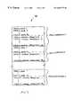
- FIG. 2illustrates the information contained in the MNEDS 30 in one embodiment.
- the MNEDS 30includes multiple sets of transducer object information 1 -x.
- Each set of object information 1 -xis adapted to a particular type for the field-bus network 10 .
- the object information 1may correspond to an SDS embodiment for the field-bus network 10 and the object information 2 may correspond to a Profibus embodiment for the field-bus network 10 .
- the manufacturer of the transducer 22provides the sets of transducer object information 1 -x in the MNEDS 30 to cover each particular type of field-bus network to which it is desired to employ the transducer 22 .
- the transducer object information 1 -xenables the transducer 22 to be employed in any of the field-bus networks included in the MNEDS 30 without modification to existing control system applications.
- the object information 1 -x in the MNEDS 30enables the component 20 to interface to a variety of differing transducers from differing manufacturers without having to be customized for each particular transducer type.
- Each set of object information 1 -xincludes a set of object_names 1 -n and a set of object_mapping_parameters 1 -m.
- the object_names 1 -nprovide a list one or more object names associated with the transducer 22 in terms of the corresponding object model. For example, if the transducer 22 is a temperature sensor then the object_names 1 -n may include temperature, units, and rate in one particular object model and may include temperature and sample period in another object model. In another example, if the transducer 22 is a combined temperature sensor and pressure sensor then the object_names 1 -n in a particular object model may include temperature, temperature units, temperature update rate, pressure, pressure units, and pressure update rate.
- the object_mapping_parameters 1 -mprovide a set of one or more parameters that enable the component node 20 to translate between the corresponding object model and the device-oriented interface 16 .
- the object_mapping_parameters 1 -m 1may correspond to an SDS object model and enable a translation between the SDS object model and the device-oriented interface 16 .
- the object_mapping_parameters 1 -mmay include a list of channels of the device-oriented interface 16 that are used for the temperature, units, and update rate variables of the transducer 22 as may be defined in the corresponding object model.
- the object_mapping_parameters 1 -mmay include an indication of whether the transducer 22 requires a triggering event in order to obtain a measurement if, for example, the correspond object model does not define a triggering event object.
- the component node 20determines a type of the field-bus network 10 to which it is attached and then reads the appropriate set of object information 1 -x from the MNEDS 30 . For example, if the component node 20 determines that it is attached to an SDS bus then it reads from the MNEDS 30 the set of object information 1 -x that corresponds to an SDS field-bus network.
- the MNEDS 30may alternatively be contained in the component node 20 in, for example, a persistent memory.
- the component node 20handles messages received via the field-bus network 10 using the information obtained from the MNEDS 30 . For example, if a message received from the application controller 24 via the field-bus network 10 contains a GET LIST command, then the component 20 transfers the object_names 1 -n obtained from the MNEDS 30 back to the application controller 24 in a response message.
- a message received from the application controller 24 via the field-bus network 10may contain a READ command that specifies one or more of the object_names 1 -n associated with the transducer 22 .
- the component 20uses the object_mapping_parameters 1 -m obtained from the MNEDS 30 to read the transducer 22 using the device-oriented interface 16 .
- one of the object_mapping_parameters 1 -mmay specify a particular channel of the device-oriented interface 16 for an object_name contained in READ command in which case the component node 20 reads the specified channel and returns the value read from the specified channel back to the application controller 24 .
- one of the object_mapping_parameters 1 -mmay indicate that a trigger on a particular channel of the device-oriented interface 16 is required to read the object_name contained in the READ command in which case the component node 20 generates the trigger on the particular channel before reading a value from the channel associated with object_name contained in READ command.
- a message received from the application controller 24 via the field-bus network 10may contain a WRITE command that specifies one or more of the object_names 1 -n associated with the transducer 22 .
- the component 20uses the object_mapping_parameters 1 -m obtained from the MNEDS 30 to write a value or values contained in the message to the transducer 22 using the device-oriented interface 16 .
- one of the object mapping_parameters 1 -mmay specify a particular channel of the device-oriented interface 16 for an object_name contained in WRITE command in which case the component node 20 writes the specified channel with a value contained in the message.
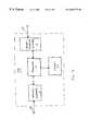
- FIG. 3illustrates one embodiment of the component node 20 .
- the component node 20 in this embodimentincludes a network interface 12 , a processor 14 , a memory 26 , and a device-oriented interface 16 .
- the network interface 12enables communication over the field-bus network 10 according to a protocol associated with the field-bus network 10 .
- a protocol associated with the field-bus network 10For example, if the field-bus network 10 is embodied as an SDS bus then the network interface 12 is adapted to the SDS protocol. Similarly, if the field-bus network 10 is embodied as a LonTalk bus then the network interface 12 is adapted to the LonTalk protocol.
- the network interface 12represents a combination of hardware and software for transmitting and receiving messages via the field-bus network 10 .
- the messagesmay include commands for accessing the transducer 22 according to the object model 18 associated with the particular type of the field-bus network 10 and messages for transporting transducer data back to the originating nodes via the field-bus network 10 according to the object model 18 .
- the device-oriented interface 16enables communication between the processor 14 and the transducer 22 via a communication link 29 .
- the device-oriented interface 16represents a combination of hardware and software that in one embodiment implements the IEEE 1451.2 standard.
- the processor 14reads the appropriate set of object information 1 -x from the MNEDS 30 of the transducer 22 via the device oriented-interface 16 depending on the type of the object model 18 .
- the type of the object model 18corresponds to the type of the field-bus network 10 which is indicated by the particular implementation of the network interface 12 .
- the processor 14copies the object information 1 -x obtained from the MNEDS 30 into the memory 26 for use when handling commands received via the field-bus network 10 .
- the memory 26may be a persistent memory which is preprogrammed with the sets of object information 1 -x.
- the processor 14After initializing the memory 26 .with the appropriate object_information 1 -x, the processor 14 receives messages via the network interface 12 that contain access requests for the transducer 22 in terms of the object model 18 . These access requests may imply methods such as GET LIST, READ value, and WRITE value, depending on the object model 18 . The processor 14 executes code for translating each of these access requests. The code for translating the access..requests may be contained in the memory 26 or in separate memory such as a persistent memory.
- the processor 14 when executing the code for translating the GET LIST methodmay read the object_names 1 -n from the memory 26 and transfer them back to a requesting node or nodes via the network interface 12 .
- the processor 14 when executing the code for translating the READ methodmay read the object_mapping_parameters 1 -m from the memory 26 and use these parameters to translate the read between the object model 18 and the device-oriented protocol 16 in a manner previously described.
- the processor 14 when executing the code for translating the WRITE methodmay read the object_mapping_parameters 1 -m from the memory 26 and use these parameters to translate the write between the object model 18 and the device-oriented protocol 16 .
- the IEEE 1451.2 standardprovides for a set interface-specific configuration information that may be stored in a device and the MNEDS 30 is an extension of that interface-specific information in the transducer 22 .
- the MNEDS 30stores multiple sets of routines for implementing the methods implied by the object model 18 .
- the MNEDS 30may store a set of routines for the methods implied by the SDS protocol and a set of routines for the methods implied by the Profibus protocol, etc.
- the processor 14determines the type of the field-bus network 10 , i.e. the type of the object model 18 , an then copies the appropriate set of routines from the MNEDS 30 into the memory 26 .
- Each set of routines copied into the memory 26may include, for example, a GET LIST routine, a READ routine, and a WRITE routine each of which is adapted to the particular object model 18 .
- Each of these routinesis coded in order to carry out the appropriate translation between the object model 18 and the device-oriented interface 16 .
- a GET LIST routine for a particular object modelmay be coded with a list of object_names associated with the transducer 22 in terms of the particular object model.
- the processor 14 when executing the GET LIST routine for the particular object modelmay generate a message containing these object_names in terms of the particular object model and then transfer the message back to the requesting node via the field-bus network 10 .
- a READ routine for a particular object modelmay be coded with specific triggering behavior required to access the transducer 22 through the device-oriented interface 16 even though the particular object model does not specify any triggering for the transducer 22 .
- a WRITE routine for a particular object modelmay be coded with specialized behavior for reading the transducer 22 in terms of the device-oriented interface 16 and the particular design of the transducer 22 .
- the special handling encoded in the READ and WRITE routines for a particular object modelmay include the manipulation of triggering channels on the device-oriented interface 16 .
- the special handling encoded in the READ and WRITE routinesmay also include special data handling or data conversion procedures such as units conversion.
- the special handling encoded in the read and write routinesmay include parameter conversion such as a conversion between a sample period specified by the particular object model and a sample rate which is required by the transducer 22 .
- the special handling encoded in the READ and WRITE routines for each particular object model supported in the MNEDS 30enables the manufacturer of the transducer 22 to implement special handling for the transducer 22 and shield this special handling from the remainder of any particular system to which the transducer 22 may be attached.
- Each of the routines copied into the memory 26provides a set of code which is directly executable by the processor 14 .
- the routinesmay be object code for the processor 14 or the processor 14 may include an interpreter for the routines.
- the processor 14may execute a Java virtual machine and each of the routines copied into the memory 26 may be a Java applet.
Landscapes
- Physics & Mathematics (AREA)
- General Physics & Mathematics (AREA)
- Engineering & Computer Science (AREA)
- Automation & Control Theory (AREA)
- Arrangements For Transmission Of Measured Signals (AREA)
Abstract
Description
1. Field of Invention
The present invention pertains to the field of control systems. More particularly, this invention relates to network independent transducers for distributed control systems.
2. Art Background
A distributed control system commonly includes a set of transducers and application controllers which are arranged to provide control of industrial and other applications. The transducers that may be employed in a distributed control system include sensors such as temperature sensors, pressure sensors, tachometers, etc. The transducers that may be employed in a distributed control system also include actuators such as valves, motors, heaters etc. Application controllers in a distributed control system may be implemented with programmable logic controllers or computer systems.
The transducers and application controllers of a distributed control system may be interconnected via a communication network. Such a communication network may be implemented with one or more of a variety of differing field-level control buses which are specialized for the process control environment. Such specialized buses may be referred to generally as field-buses. The transducers and application controllers are usually connected as nodes on such a field-bus network.
Typically, existing field-bus networks represent the transducers in a distributed control system using a particular object model. In addition, the object models of transducers usually differ among existing field bus networks. For example, SDS networks have a transducer object model that is incompatible with the transducer object model used in a DeviceNet network.
As a consequence, the manufacturers of transducers must typically provide permutations of their transducers for each of the field bus networks for which they desire to market their products. Typically, each permutation of a transducer is designed and manufactured with the appropriate network interface elements that enable the transducer to be accessed via a particular field bus using the object model appropriate for the particular field-bus. Unfortunately, the permutations of network interface designs for the differing types of field bus networks greatly increases the time and cost required to develop new transducers and increases the cost of supporting the transducers in the field.
A distributed control system is disclosed which includes a network-independent transducer and an electronic data sheet that enables the transducer to be accessed via a variety of differing types of field-bus networks. The electronic data sheet stores a set of object information corresponding to a set of differing object models associated with the differing types of field-bus networks. The distributed control system includes a component node which couples to a particular one of the differing types of field-bus networks and which couples to the transducer through a standard interface. The component node uses the object information to translate between the particular one of the object models and the standard interface during an access of the transducer that originates on the particular one of the differing types of field-bus networks. The electronic data sheet allows the transducer to be employed in a variety of field-bus networks without modifications to existing control system applications.
Other features and advantages of the present invention will be apparent from the detailed description that follows.
The present invention is described with respect to particular exemplary embodiments thereof and reference is accordingly made to the drawings in which:
FIG. 1 shows a distributed control system including a transducer having a multiple network electronic data sheet (MNEDS) that enables it to be accessed via a variety of differing types of field-bus networks;
FIG. 2 illustrates the information contained in the MNEDS in one embodiment;
FIG. 3 illustrates one embodiment of a component node which translates between a network object model and a standard transducer interface.
FIG. 1 shows a distributed control system100 including atransducer 22 having a multiple network electronic data sheet (MNEDS)30 that enables it to be accessed via a variety of differing types of field-bus networks. The distributed control system100 includes acomponent node 20 that interfaces thetransducer 22 to a field-bus network10.
The transducer MNEDS30 stores a set of object information corresponding to each of a set of differing object models associated with the differing types of field-bus networks which may be embodied in the field-bus network10. In one embodiment, the MNEDS30 is a persistent memory in thetransducer 22.
The field-bus network10 is one of a variety of field level control buses adapted for the process control environment. The field-bus network10 may be an SDS bus, a DeviceNet bus, a LonTalk bus, an Echelon bus, a Foundation Fieldbus, or a Profibus to name a few examples. These differing types of field level control buses generally employ differing object models for thetransducer 22.
Other nodes on the field-bus network10 such as an application controller24 view thetransducer 22 according to apredetermined object model 18 that is associated with the field-bus network10. For example, if the field-bus network10 is an SDS bus then thepredetermined object model 18 is an object model that is associated with the SDS protocol. Similarly, if the field-bus network10 is a Profibus bus, then thepredetermined object model 18 is an object model that is associated with the SDS protocol.
The MNEDS30 enables thecomponent node 20 to translate between theobject model 18 and a device-oriented interface 16 which is used to interface thecomponent node 20 to thetransducer 22.
The device-oriented interface 16 provides a set of channels for thetransducer 22. Each channel, in general, is associated with a variable of thetransducer 22. For example, thetransducer 22 may be a combined temperature and pressure sensor in which temperature variables are transferred via a first channel of the device-oriented interface 16 and in which the pressure variables are transferred via a second channel of the device-oriented interface 16. In addition, one or more channels of the device-oriented interface 16 may be used for triggering signals associated with the first and second channels.
One standard interface suitable for use as the device-oriented interface 16 is the IEEE 1451.2 standard. The IEEE 1451.2 standard specifies multiple channels for obtaining device variables and defines a format of information pertaining to each attached device. The information pertaining to a particular attached device describes the type of device, the data rate, units of measure and special triggering requirements, etc. Theobject model 18 defines a set of methods for accessing one or more objects associated with thetransducer 22. In general, an object associated with thetransducer 22 is a variable such a measured variable or actuated variable or variables that provide parameters for the measurements and/or actuations performed by thetransducer 22. An example of an object associated with a temperature sensor is a temperature variable. Another example of an object associated with a temperature sensor is an update rate variable or a sample rate or sampling period variable depending on theparticular object model 18. Examples of objects associated with a heater include a temperature variable and a units variable (degrees F., degrees C.) depending on theparticular object model 18.
An example of a method for accessing the objects of thetransducer 22 is a GET LIST method. The GET LIST method may be used by the application controller24 to obtain a list of objects associated with thetransducer 22 in terms of theobject model 18. Another example of a method is a READ method which may be used by the application controller24 to obtain values associated with one or more objects of thetransducer 22. Another example of a method is a WRITE method which may be used by the application controller24 to write values associated with one or more objects of thetransducer 22.
FIG. 2 illustrates the information contained in the MNEDS30 in one embodiment. The MNEDS30 includes multiple sets of transducer object information1-x. Each set of object information1-x is adapted to a particular type for the field-bus network10. For example, the object information1 may correspond to an SDS embodiment for the field-bus network10 and theobject information 2 may correspond to a Profibus embodiment for the field-bus network10.
The manufacturer of thetransducer 22 provides the sets of transducer object information1-x in theMNEDS 30 to cover each particular type of field-bus network to which it is desired to employ thetransducer 22. The transducer object information1-x enables thetransducer 22 to be employed in any of the field-bus networks included in theMNEDS 30 without modification to existing control system applications. In addition, the object information1-x in theMNEDS 30 enables thecomponent 20 to interface to a variety of differing transducers from differing manufacturers without having to be customized for each particular transducer type.
Each set of object information1-x includes a set of object_names1-n and a set of object_mapping_parameters1-m. The object_names1-n provide a list one or more object names associated with thetransducer 22 in terms of the corresponding object model. For example, if thetransducer 22 is a temperature sensor then the object_names1-n may include temperature, units, and rate in one particular object model and may include temperature and sample period in another object model. In another example, if thetransducer 22 is a combined temperature sensor and pressure sensor then the object_names1-n in a particular object model may include temperature, temperature units, temperature update rate, pressure, pressure units, and pressure update rate.
The object_mapping_parameters1-m provide a set of one or more parameters that enable thecomponent node 20 to translate between the corresponding object model and the device-orientedinterface 16. For example, the object_mapping_parameters1-m1may correspond to an SDS object model and enable a translation between the SDS object model and the device-orientedinterface 16.
As a translation example, if thetransducer 22 is a temperature sensor then the object_mapping_parameters1-m may include a list of channels of the device-orientedinterface 16 that are used for the temperature, units, and update rate variables of thetransducer 22 as may be defined in the corresponding object model. The object_mapping_parameters1-m may include an indication of whether thetransducer 22 requires a triggering event in order to obtain a measurement if, for example, the correspond object model does not define a triggering event object.
At reset or system initialization, thecomponent node 20 determines a type of the field-bus network10 to which it is attached and then reads the appropriate set of object information1-x from theMNEDS 30. For example, if thecomponent node 20 determines that it is attached to an SDS bus then it reads from theMNEDS 30 the set of object information1-x that corresponds to an SDS field-bus network.
TheMNEDS 30 may alternatively be contained in thecomponent node 20 in, for example, a persistent memory.
Thecomponent node 20 handles messages received via the field-bus network10 using the information obtained from theMNEDS 30. For example, if a message received from the application controller24 via the field-bus network10 contains a GET LIST command, then thecomponent 20 transfers the object_names1-n obtained from theMNEDS 30 back to the application controller24 in a response message.
A message received from the application controller24 via the field-bus network10 may contain a READ command that specifies one or more of the object_names1-n associated with thetransducer 22. In response, thecomponent 20 uses the object_mapping_parameters1-m obtained from theMNEDS 30 to read thetransducer 22 using the device-orientedinterface 16. For example, one of the object_mapping_parameters1-m may specify a particular channel of the device-orientedinterface 16 for an object_name contained in READ command in which case thecomponent node 20 reads the specified channel and returns the value read from the specified channel back to the application controller24. In another example, one of the object_mapping_parameters1-m may indicate that a trigger on a particular channel of the device-orientedinterface 16 is required to read the object_name contained in the READ command in which case thecomponent node 20 generates the trigger on the particular channel before reading a value from the channel associated with object_name contained in READ command.
A message received from the application controller24 via the field-bus network10 may contain a WRITE command that specifies one or more of the object_names1-n associated with thetransducer 22. In response, thecomponent 20 uses the object_mapping_parameters1-m obtained from theMNEDS 30 to write a value or values contained in the message to thetransducer 22 using the device-orientedinterface 16. For example, one of the object mapping_parameters1-m may specify a particular channel of the device-orientedinterface 16 for an object_name contained in WRITE command in which case thecomponent node 20 writes the specified channel with a value contained in the message.
FIG. 3 illustrates one embodiment of thecomponent node 20. Thecomponent node 20 in this embodiment includes anetwork interface 12, aprocessor 14, amemory 26, and a device-orientedinterface 16.
Thenetwork interface 12 enables communication over the field-bus network10 according to a protocol associated with the field-bus network10. For example, if the field-bus network10 is embodied as an SDS bus then thenetwork interface 12 is adapted to the SDS protocol. Similarly, if the field-bus network10 is embodied as a LonTalk bus then thenetwork interface 12 is adapted to the LonTalk protocol.
Thenetwork interface 12 represents a combination of hardware and software for transmitting and receiving messages via the field-bus network10. The messages may include commands for accessing thetransducer 22 according to theobject model 18 associated with the particular type of the field-bus network10 and messages for transporting transducer data back to the originating nodes via the field-bus network10 according to theobject model 18.
The device-orientedinterface 16 enables communication between theprocessor 14 and thetransducer 22 via acommunication link 29. The device-orientedinterface 16 represents a combination of hardware and software that in one embodiment implements the IEEE 1451.2 standard.
At system reset or initialization, theprocessor 14 reads the appropriate set of object information1-x from theMNEDS 30 of thetransducer 22 via the device oriented-interface 16 depending on the type of theobject model 18. The type of theobject model 18 corresponds to the type of the field-bus network10 which is indicated by the particular implementation of thenetwork interface 12. Theprocessor 14 copies the object information1-x obtained from the MNEDS30 into thememory 26 for use when handling commands received via the field-bus network10. Alternatively, thememory 26 may be a persistent memory which is preprogrammed with the sets of object information1-x.
After initializing the memory26.with the appropriate object_information1-x, theprocessor 14 receives messages via thenetwork interface 12 that contain access requests for thetransducer 22 in terms of theobject model 18. These access requests may imply methods such as GET LIST, READ value, and WRITE value, depending on theobject model 18. Theprocessor 14 executes code for translating each of these access requests. The code for translating the access..requests may be contained in thememory 26 or in separate memory such as a persistent memory.
For example, theprocessor 14 when executing the code for translating the GET LIST method may read the object_names1-n from thememory 26 and transfer them back to a requesting node or nodes via thenetwork interface 12. As another example, theprocessor 14 when executing the code for translating the READ method may read the object_mapping_parameters1-m from thememory 26 and use these parameters to translate the read between theobject model 18 and the device-orientedprotocol 16 in a manner previously described. Similarly, theprocessor 14 when executing the code for translating the WRITE method may read the object_mapping_parameters1-m from thememory 26 and use these parameters to translate the write between theobject model 18 and the device-orientedprotocol 16.
In one embodiment, the IEEE 1451.2 standard provides for a set interface-specific configuration information that may be stored in a device and theMNEDS 30 is an extension of that interface-specific information in thetransducer 22.
In an alternative embodiment, theMNEDS 30 stores multiple sets of routines for implementing the methods implied by theobject model 18. For example, theMNEDS 30 may store a set of routines for the methods implied by the SDS protocol and a set of routines for the methods implied by the Profibus protocol, etc. At power up or initialization theprocessor 14 determines the type of the field-bus network10, i.e. the type of theobject model 18, an then copies the appropriate set of routines from the MNEDS30 into thememory 26.
Each set of routines copied into thememory 26 may include, for example, a GET LIST routine, a READ routine, and a WRITE routine each of which is adapted to theparticular object model 18. Each of these routines is coded in order to carry out the appropriate translation between theobject model 18 and the device-orientedinterface 16.
For example, a GET LIST routine for a particular object model may be coded with a list of object_names associated with thetransducer 22 in terms of the particular object model. Theprocessor 14 when executing the GET LIST routine for the particular object model may generate a message containing these object_names in terms of the particular object model and then transfer the message back to the requesting node via the field-bus network10.
As another example, a READ routine for a particular object model may be coded with specific triggering behavior required to access thetransducer 22 through the device-orientedinterface 16 even though the particular object model does not specify any triggering for thetransducer 22. Similarly, a WRITE routine for a particular object model may be coded with specialized behavior for reading thetransducer 22 in terms of the device-orientedinterface 16 and the particular design of thetransducer 22.
The special handling encoded in the READ and WRITE routines for a particular object model may include the manipulation of triggering channels on the device-orientedinterface 16. The special handling encoded in the READ and WRITE routines may also include special data handling or data conversion procedures such as units conversion. The special handling encoded in the read and write routines may include parameter conversion such as a conversion between a sample period specified by the particular object model and a sample rate which is required by thetransducer 22.
The special handling encoded in the READ and WRITE routines for each particular object model supported in theMNEDS 30 enables the manufacturer of thetransducer 22 to implement special handling for thetransducer 22 and shield this special handling from the remainder of any particular system to which thetransducer 22 may be attached.
Each of the routines copied into thememory 26 provides a set of code which is directly executable by theprocessor 14. The routines may be object code for theprocessor 14 or theprocessor 14 may include an interpreter for the routines. For example, theprocessor 14 may execute a Java virtual machine and each of the routines copied into thememory 26 may be a Java applet.
The foregoing detailed description of the present invention is provided for the purposes of illustration and is not intended to be exhaustive or to limit the invention to the precise embodiment disclosed. Accordingly, the scope of the present invention is defined by the appended claims.
Claims (16)
1. A distributed control system, comprising:
transducer having a standard interface and having an electronic data sheet that stores a set of object information corresponding to each of a set of object models for representing the transducer wherein each object model is characterized by a corresponding set of methods for accessing the transducer;
component node coupled to coupled to the transducer through the standard interface and coupled to a network that represents the transducer using a particular one of the object models, the component node having means for using the object information to translate between the particular one of the object models and the standard interface during an access of the transducer that uses the methods of the particular one of the object models.
2. The distributed control system ofclaim 1 , wherein the component node further comprises means for reading a subset of object information corresponding to the particular one of the object models from the electronic data sheet and for storing the subset of object information for use while translating.
3. The distributed control system ofclaim 1 , wherein each set of object information includes a list of object names associated with the transducer in terms of the corresponding object model.
4. The distributed control system ofclaim 3 , wherein each set of object information further includes a set of object mapping parameters that enable the component node to translate between the corresponding object model and the standard interface.
5. The distributed control system ofclaim 1 , wherein each set of object information includes a set of routines for handling the methods associated with the corresponding object model.
6. The distributed control system ofclaim 1 , wherein at system initialization the component node determines the network to which it is coupled an then reads the corresponding set of object information for the network from the transducer.
7. A transducer for a distributed control system, comprising:
electronic data sheet that stores a set of object information corresponding to each of a set of object models for representing the transducer wherein each object model is characterized by a corresponding set of methods for accessing the transducer;
such that the object information enables a component node to translate between a particular one of the object models and a standard interface to the transducer during an access of the transducer that uses the methods of the particular one of the object models.
8. The transducer ofclaim 7 , wherein each set of object information includes a list of object names associated with the transducer in terms of the corresponding object model.
9. The transducer ofclaim 8 , wherein each set of object information further includes a set of object mapping parameters that enable the component node to translate between the corresponding object model and the standard interface.
10. The transducer ofclaim 7 , wherein each set of object information includes a set of routines for handling methods associated with the corresponding object model.
11. A component node for a distributed control system, comprising:
network interface that enables communication via a network having an object model for representing a transducer wherein the object model is characterized by a set of methods for accessing the transducer;
standard interface that enables communication with the transducer;
processor that reads a set of object information corresponding to the object model from the transducer and translates between the object model and the standard interface during an access of the transducer that uses the methods.
12. The component node ofclaim 11 , wherein the object information includes a list of object names associated with the transducer in terms of the object model.
13. The component node ofclaim 12 , wherein the object information further includes a set of object mapping parameters that enable the component node to translate between the object model and the standard interface.
14. The component node ofclaim 11 , wherein the object information includes a set of routines for handling the methods associated with the object model.
15. The component node ofclaim 11 , wherein at system initialization the processor reads the object information from the transducer.
16. The component node ofclaim 15 , further comprising a memory into which the processor stores the object information read from the transducer at system initialization such that the processor translates between the object model and the standard interface in response to the object information stored in the memory.
Priority Applications (1)
| Application Number | Priority Date | Filing Date | Title |
|---|---|---|---|
| US09/020,630US6687772B1 (en) | 1998-02-09 | 1998-02-09 | Transducers with electronic data sheets that enable transducer access using multiple types of transducer object models |
Applications Claiming Priority (1)
| Application Number | Priority Date | Filing Date | Title |
|---|---|---|---|
| US09/020,630US6687772B1 (en) | 1998-02-09 | 1998-02-09 | Transducers with electronic data sheets that enable transducer access using multiple types of transducer object models |
Publications (1)
| Publication Number | Publication Date |
|---|---|
| US6687772B1true US6687772B1 (en) | 2004-02-03 |
Family
ID=30442174
Family Applications (1)
| Application Number | Title | Priority Date | Filing Date |
|---|---|---|---|
| US09/020,630Expired - Fee RelatedUS6687772B1 (en) | 1998-02-09 | 1998-02-09 | Transducers with electronic data sheets that enable transducer access using multiple types of transducer object models |
Country Status (1)
| Country | Link |
|---|---|
| US (1) | US6687772B1 (en) |
Cited By (5)
| Publication number | Priority date | Publication date | Assignee | Title |
|---|---|---|---|---|
| US20020147874A1 (en)* | 2000-12-29 | 2002-10-10 | Henrik Niklasson | Control arrangement |
| US20060101111A1 (en)* | 2004-10-05 | 2006-05-11 | Csi Technology, Inc. | Method and apparatus transferring arbitrary binary data over a fieldbus network |
| US20070232290A1 (en)* | 2006-04-03 | 2007-10-04 | Tatman Lance A | System and method for measuring user behavior and use of mobile equipment |
| US20090168806A1 (en)* | 2007-12-31 | 2009-07-02 | Schneider Automation Inc. | Tuning of industrial automation system performance based on device operating characteristics |
| US11017098B2 (en) | 2018-06-28 | 2021-05-25 | Seagate Technology Llc | Collection of uncorrelated entropy during a power down sequence |
Citations (14)
| Publication number | Priority date | Publication date | Assignee | Title |
|---|---|---|---|---|
| US5650777A (en)* | 1995-06-07 | 1997-07-22 | Rosemount Inc. | Conversion circuit for process control system |
| US5717385A (en)* | 1990-11-28 | 1998-02-10 | Hitachi, Ltd. | Field bus system and virtual field apparatus |
| US5764891A (en)* | 1996-02-15 | 1998-06-09 | Rosemount Inc. | Process I/O to fieldbus interface circuit |
| US5923557A (en)* | 1997-08-01 | 1999-07-13 | Hewlett-Packard Company | Method and apparatus for providing a standard interface to process control devices that are adapted to differing field-bus protocols |
| US5941966A (en)* | 1997-05-05 | 1999-08-24 | International Business Machines Corporation | Method and apparatus using a plural level processor for controlling a data bus |
| US6032203A (en)* | 1997-04-07 | 2000-02-29 | General Electric Company | System for interfacing between a plurality of processors having different protocols in switchgear and motor control center applications by creating description statements specifying rules |
| US6047219A (en)* | 1997-11-24 | 2000-04-04 | Hewlett-Packard Company | Specification interpreting distributed system |
| US6104962A (en)* | 1998-03-26 | 2000-08-15 | Rockwell Technologies, Llc | System for and method of allocating processing tasks of a control program configured to control a distributed control system |
| US6115713A (en)* | 1990-01-30 | 2000-09-05 | Johnson Controls Technology Company | Networked facilities management system |
| US6151640A (en)* | 1998-01-23 | 2000-11-21 | Schneider Automation Inc. | Control I/O module having the ability to interchange bus protocols for bus networks independent of the control I/O module |
| US6308255B1 (en)* | 1998-05-26 | 2001-10-23 | Advanced Micro Devices, Inc. | Symmetrical multiprocessing bus and chipset used for coprocessor support allowing non-native code to run in a system |
| US6333940B1 (en)* | 1993-03-09 | 2001-12-25 | Hubbell Incorporated | Integrated digital loop carrier system with virtual tributary mapper circuit |
| US6385769B1 (en)* | 1999-02-03 | 2002-05-07 | International Business Machines Corporation | Text based object oriented program code with a visual program builder and parser support for predetermined and not predetermined formats |
| US6385193B1 (en)* | 1996-11-07 | 2002-05-07 | At&T | Wan-based gateway |
- 1998
- 1998-02-09USUS09/020,630patent/US6687772B1/ennot_activeExpired - Fee Related
Patent Citations (17)
| Publication number | Priority date | Publication date | Assignee | Title |
|---|---|---|---|---|
| US6115713A (en)* | 1990-01-30 | 2000-09-05 | Johnson Controls Technology Company | Networked facilities management system |
| US5717385A (en)* | 1990-11-28 | 1998-02-10 | Hitachi, Ltd. | Field bus system and virtual field apparatus |
| US20010045882A1 (en)* | 1990-11-28 | 2001-11-29 | Makoto Kogure | Field bus system and virtual field apparatus |
| US6333940B1 (en)* | 1993-03-09 | 2001-12-25 | Hubbell Incorporated | Integrated digital loop carrier system with virtual tributary mapper circuit |
| US6307483B1 (en)* | 1995-06-07 | 2001-10-23 | Rosemount Inc. | Conversion circuit for process control system |
| US5650777A (en)* | 1995-06-07 | 1997-07-22 | Rosemount Inc. | Conversion circuit for process control system |
| US5963147A (en)* | 1995-06-07 | 1999-10-05 | Rosemont Inc. | Conversion circuit for process control system |
| US5764891A (en)* | 1996-02-15 | 1998-06-09 | Rosemount Inc. | Process I/O to fieldbus interface circuit |
| US6385193B1 (en)* | 1996-11-07 | 2002-05-07 | At&T | Wan-based gateway |
| US6032203A (en)* | 1997-04-07 | 2000-02-29 | General Electric Company | System for interfacing between a plurality of processors having different protocols in switchgear and motor control center applications by creating description statements specifying rules |
| US5941966A (en)* | 1997-05-05 | 1999-08-24 | International Business Machines Corporation | Method and apparatus using a plural level processor for controlling a data bus |
| US5923557A (en)* | 1997-08-01 | 1999-07-13 | Hewlett-Packard Company | Method and apparatus for providing a standard interface to process control devices that are adapted to differing field-bus protocols |
| US6047219A (en)* | 1997-11-24 | 2000-04-04 | Hewlett-Packard Company | Specification interpreting distributed system |
| US6151640A (en)* | 1998-01-23 | 2000-11-21 | Schneider Automation Inc. | Control I/O module having the ability to interchange bus protocols for bus networks independent of the control I/O module |
| US6104962A (en)* | 1998-03-26 | 2000-08-15 | Rockwell Technologies, Llc | System for and method of allocating processing tasks of a control program configured to control a distributed control system |
| US6308255B1 (en)* | 1998-05-26 | 2001-10-23 | Advanced Micro Devices, Inc. | Symmetrical multiprocessing bus and chipset used for coprocessor support allowing non-native code to run in a system |
| US6385769B1 (en)* | 1999-02-03 | 2002-05-07 | International Business Machines Corporation | Text based object oriented program code with a visual program builder and parser support for predetermined and not predetermined formats |
Cited By (9)
| Publication number | Priority date | Publication date | Assignee | Title |
|---|---|---|---|---|
| US20020147874A1 (en)* | 2000-12-29 | 2002-10-10 | Henrik Niklasson | Control arrangement |
| US7093050B2 (en)* | 2000-12-29 | 2006-08-15 | Empir Ab | Control arrangement |
| US20060101111A1 (en)* | 2004-10-05 | 2006-05-11 | Csi Technology, Inc. | Method and apparatus transferring arbitrary binary data over a fieldbus network |
| US20070232290A1 (en)* | 2006-04-03 | 2007-10-04 | Tatman Lance A | System and method for measuring user behavior and use of mobile equipment |
| US8914018B2 (en) | 2006-04-03 | 2014-12-16 | Keysight Technologies, Inc. | System and method for measuring user behavior and use of mobile equipment |
| US20090168806A1 (en)* | 2007-12-31 | 2009-07-02 | Schneider Automation Inc. | Tuning of industrial automation system performance based on device operating characteristics |
| WO2009088764A3 (en)* | 2007-12-31 | 2009-10-08 | Schneider Automation Inc. | Tuning of industrial automation system performance based on device operating characteristics |
| US8634325B2 (en) | 2007-12-31 | 2014-01-21 | Schneide Electric USA, Inc. | Tuning of industrial automation system performance based on device operating characteristics |
| US11017098B2 (en) | 2018-06-28 | 2021-05-25 | Seagate Technology Llc | Collection of uncorrelated entropy during a power down sequence |
Similar Documents
| Publication | Publication Date | Title |
|---|---|---|
| US6047219A (en) | Specification interpreting distributed system | |
| US5923557A (en) | Method and apparatus for providing a standard interface to process control devices that are adapted to differing field-bus protocols | |
| EP0928443B1 (en) | A network accessible interface for a process control network | |
| US7984199B2 (en) | Configuration of field devices on a network | |
| EP3235185B1 (en) | Data transfer on an industrial process network | |
| JP5030584B2 (en) | Interface module for use with MODBUS device network and Fieldbus device network | |
| EP2628060B1 (en) | Field device with self description | |
| CA2662877C (en) | System and method for functionalization in line with demand, for control and regulatory devices | |
| US20130080585A1 (en) | Method for transmitting data via a canopen bus | |
| US8219790B2 (en) | Determining device-internal parameter addresses from fieldbus-specific parameter addresses of a field device | |
| US6687772B1 (en) | Transducers with electronic data sheets that enable transducer access using multiple types of transducer object models | |
| US20060168245A1 (en) | Software component for a distributed control system, and method for designing a control system | |
| JP7267663B2 (en) | Internet-of-things interlocking device and method for existing fieldbus-based automatic control system | |
| CN106407139B (en) | Method and Peripheral Components and CPU Unit for Transferring HART Variables | |
| Pal et al. | Development of network capable smart transducer interface for traditional sensors and actuators | |
| JP2003515272A (en) | Communication device or communication method | |
| Farsi et al. | An introduction to CANopen and CANopen communication issues | |
| CN102132528B (en) | Communication system and interface device of communication system | |
| Mitterer et al. | A dynamic sensor interpreter for robotic systems | |
| Farsi et al. | CANopen: the open communications solution | |
| CN114124949A (en) | Serial port agent device and distribution automation power system applying same | |
| Haus et al. | Application integration the other way around | |
| HK1143470B (en) | Block-oriented control system having wireless gateway for communication with wireless field devices |
Legal Events
| Date | Code | Title | Description |
|---|---|---|---|
| AS | Assignment | Owner name:HEWLETT-PACKARD COMPANY, CALIFORNIA Free format text:ASSIGNMENT OF ASSIGNORS INTEREST;ASSIGNOR:EIDSON, JOHN C.;REEL/FRAME:009205/0348 Effective date:19980506 | |
| AS | Assignment | Owner name:HEWLETT-PACKARD COMPANY, COLORADO Free format text:MERGER;ASSIGNOR:HEWLETT-PACKARD COMPANY;REEL/FRAME:010759/0049 Effective date:19980520 | |
| AS | Assignment | Owner name:AGILENT TECHNOLOGIES INC, CALIFORNIA Free format text:ASSIGNMENT OF ASSIGNORS INTEREST;ASSIGNOR:HEWLETT-PACKARD COMPANY;REEL/FRAME:010977/0540 Effective date:19991101 | |
| FPAY | Fee payment | Year of fee payment:4 | |
| REMI | Maintenance fee reminder mailed | ||
| LAPS | Lapse for failure to pay maintenance fees | ||
| STCH | Information on status: patent discontinuation | Free format text:PATENT EXPIRED DUE TO NONPAYMENT OF MAINTENANCE FEES UNDER 37 CFR 1.362 | |
| FP | Lapsed due to failure to pay maintenance fee | Effective date:20120203 |