US6687754B1 - Method of detecting a device in a network - Google Patents
Method of detecting a device in a networkDownload PDFInfo
- Publication number
- US6687754B1 US6687754B1US09/384,687US38468799AUS6687754B1US 6687754 B1US6687754 B1US 6687754B1US 38468799 AUS38468799 AUS 38468799AUS 6687754 B1US6687754 B1US 6687754B1
- Authority
- US
- United States
- Prior art keywords
- network
- identification frame
- identification
- devices
- peer
- Prior art date
- Legal status (The legal status is an assumption and is not a legal conclusion. Google has not performed a legal analysis and makes no representation as to the accuracy of the status listed.)
- Expired - Lifetime
Links
- 238000000034methodMethods0.000titleclaimsabstractdescription38
- 238000004891communicationMethods0.000claimsdescription18
- 230000008569processEffects0.000claimsdescription12
- 230000001902propagating effectEffects0.000claimsdescription7
- 230000005540biological transmissionEffects0.000claimsdescription6
- 230000000644propagated effectEffects0.000claimsdescription6
- 230000003044adaptive effectEffects0.000claimsdescription4
- 125000004122cyclic groupChemical group0.000claimsdescription4
- 230000002401inhibitory effectEffects0.000claims9
- 230000006870functionEffects0.000abstractdescription7
- 238000005516engineering processMethods0.000description4
- 238000004590computer programMethods0.000description3
- 238000010586diagramMethods0.000description3
- 238000001514detection methodMethods0.000description2
- 230000006855networkingEffects0.000description2
- 230000002093peripheral effectEffects0.000description2
- 230000007246mechanismEffects0.000description1
- 238000012986modificationMethods0.000description1
- 230000004048modificationEffects0.000description1
Images

Classifications
- H—ELECTRICITY
- H04—ELECTRIC COMMUNICATION TECHNIQUE
- H04L—TRANSMISSION OF DIGITAL INFORMATION, e.g. TELEGRAPHIC COMMUNICATION
- H04L41/00—Arrangements for maintenance, administration or management of data switching networks, e.g. of packet switching networks
- H04L41/08—Configuration management of networks or network elements
- H04L41/0876—Aspects of the degree of configuration automation
- H04L41/0886—Fully automatic configuration
- H—ELECTRICITY
- H04—ELECTRIC COMMUNICATION TECHNIQUE
- H04L—TRANSMISSION OF DIGITAL INFORMATION, e.g. TELEGRAPHIC COMMUNICATION
- H04L12/00—Data switching networks
- H04L12/28—Data switching networks characterised by path configuration, e.g. LAN [Local Area Networks] or WAN [Wide Area Networks]
- H04L12/42—Loop networks
- H04L12/427—Loop networks with decentralised control
- H04L12/433—Loop networks with decentralised control with asynchronous transmission, e.g. token ring, register insertion
- H—ELECTRICITY
- H04—ELECTRIC COMMUNICATION TECHNIQUE
- H04L—TRANSMISSION OF DIGITAL INFORMATION, e.g. TELEGRAPHIC COMMUNICATION
- H04L41/00—Arrangements for maintenance, administration or management of data switching networks, e.g. of packet switching networks
- H04L41/08—Configuration management of networks or network elements
- H04L41/0803—Configuration setting
- H04L41/0823—Configuration setting characterised by the purposes of a change of settings, e.g. optimising configuration for enhancing reliability
- H04L41/0836—Configuration setting characterised by the purposes of a change of settings, e.g. optimising configuration for enhancing reliability to enhance reliability, e.g. reduce downtime
- H—ELECTRICITY
- H04—ELECTRIC COMMUNICATION TECHNIQUE
- H04L—TRANSMISSION OF DIGITAL INFORMATION, e.g. TELEGRAPHIC COMMUNICATION
- H04L41/00—Arrangements for maintenance, administration or management of data switching networks, e.g. of packet switching networks
- H04L41/08—Configuration management of networks or network elements
- H04L41/085—Retrieval of network configuration; Tracking network configuration history
- H04L41/0853—Retrieval of network configuration; Tracking network configuration history by actively collecting configuration information or by backing up configuration information
- H—ELECTRICITY
- H04—ELECTRIC COMMUNICATION TECHNIQUE
- H04L—TRANSMISSION OF DIGITAL INFORMATION, e.g. TELEGRAPHIC COMMUNICATION
- H04L41/00—Arrangements for maintenance, administration or management of data switching networks, e.g. of packet switching networks
- H04L41/12—Discovery or management of network topologies
- H—ELECTRICITY
- H04—ELECTRIC COMMUNICATION TECHNIQUE
- H04L—TRANSMISSION OF DIGITAL INFORMATION, e.g. TELEGRAPHIC COMMUNICATION
- H04L12/00—Data switching networks
- H04L12/28—Data switching networks characterised by path configuration, e.g. LAN [Local Area Networks] or WAN [Wide Area Networks]
- H04L12/40—Bus networks
- H04L12/40169—Flexible bus arrangements
Definitions
- the present inventionrelates generally to networks, and more particularly, to a method for detecting devices connected to such a network.
- Networkssuch as computerized Local Area Networks (LANs) are commonly used to interconnect many different devices, such as computers. There is an increasing requirement to provide communication between these devices. This is because of the number of devices that are to be connected together, and the increases in the amount of information that is to be communicated between them. As a result, a number of networking technologies have been developed, and many standards have been developed around these technologies.
- LANsLocal Area Networks
- One example of such a technologyincludes a token ring network in which many devices are connected in either a physical or logical ring, and a token is transmitted around the ring from device to device.
- a tokenis transmitted around the ring from device to device.
- a deviceWhen a device requires access to the ring to transmit information, it waits to receive the token and then holds the token while transmitting data on the network. Other devices are prevented from receiving the token while information is being transmitted by the token holder.
- Ethernetis a commonly used LAN scheme in which multiple devices are connected together. In some cases, only one device can transmit data at a time.
- a devicetransmits data in the form of a packet that includes a destination address. The packet propagates throughout the network, and is received by all other devices connected to the network. The destination device may copy the entire packet. The other devices may reject the packet after determining that it is addressed to the destination device.
- the system administrator or central management systemis an entity that a user of a device typically contacts when the user encounters a problem related to the network.
- the increasing growth and complexity of LANsmakes it more difficult for a user to contact the system administrator. For example, the identity and/or location of the system administrator may not be known to many users.
- reliance on these centralized management systemscan cause congestion in the LAN due to the number of packets destined to the system administrator.
- a centralized management systemincreases the risk of network failure because of the excessive reliance on the system administrator.
- the present inventionis directed to a method for detecting characteristics of a plurality of peer devices connected to a network that includes generating. an identification frame by one of the peer devices.
- the identification framemay be propagated to only the other peer devices in the network.
- the identification framemay include a network address or a group address.
- An error or a predefined MAC addressmay be introduced into the frame to cause the peer device to recognize the frame.
- the networkmay be a token ring or an Ethernet network.
- the errormay be a corruption of the cyclic redundancy control (CRC) check bit or a predefined combination of the padding bits of the identification frame.
- CRCcyclic redundancy control
- the present inventionis directed to a computer network that includes a plurality of peer devices connected to the network by a plurality of links and switches.
- An identification frameis propagated from one peer device to the other peer devices to enable a plurality of features of the peer devices receiving the identification frame.
- the identification framemay be a MAC frame.
- the identification framemay be exchanged in a management information format.
- Each of the switchesmay have a media access controller connected between the selected device and a transceiver circuit.
- the transceiver circuitmay include a controller for recognizing an error or a predefined MAC address in the identification frame.
- the present inventionis directed to a network including a plurality of peer devices that includes a plurality of switches connected to the devices.
- the switchesmay include computer software residing on a computer readable medium at each switch to recognize an identification frame from one of the peer devices.
- the switchmay propagate the identification frame only to other ones of the peer devices in the network.
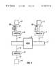
- FIG. 1is a block diagram of an exemplary network.
- FIG. 2illustrates a block diagram of a switch that can be implemented in the network of FIG. 1 .
- FIG. 3illustrates an identification frame transmitted among a plurality of devices connected to the network of FIG. 1 .
- a system administratoris responsible for managing a network.
- the system administrator's responsibilitiesmay include configuring a device that is added to the network.
- the system administratoris responsible for the central management of the network. This means that the system administrator must enable certain functionalities of the devices, the network, and other attached peripherals.
- This requirement of centralized management of the system by the administratorincreases the risk in a network that a network failure may occur at the system administrator. As a result, the entire network may be inoperable during the time that the network failure is being remedied.
- a network failure at the system administratormay also cause other network failures throughout the network that initiate at the system administrator.
- the system administratoris responsible for detecting the presence of a failed link and notifying the devices of the failure. However, if the administrator is unable to notify the devices, the devices may not receive important data. This means that the device may not be able to execute or continue a process running on its system.
- the present inventorhas discovered a method in which a device connected to a network may obtain characteristic information about other similarly connected devices without notifying or relying on the system administrator.
- the characteristic of informationis distributed using an identification frame that is propagated to various devices connected to the network to cause these devices to perform various functions.
- FIG. 1illustrates an example network, such as a local area network (LAN) 1 .
- the network 1may be an Ethernet medium that has a bus-type architecture.
- the network 1may be a token-ring medium having a ring-type architecture.
- the network 1may be a heterogeneous system including several connected devices, such as computers or peripherals, to which the devices can share access.
- the networkmay be a homogeneous network in which every connected device uses the same protocol.
- FIG. 1shows that a device 2 is connected to the network 1 by a switch 8 via links 9 .
- a device 3is connected to the network 1 by a switch 7 via links 5
- a device 4is connected to the network 1 by a switch 13 via links 15 .
- Each of the switches 7 , 8 , and 13may include ports (not shown) for propagating data to or from an attached device.
- Each of the switches 7 , 8 , and 13may include multiple ports for connecting multiple devices to the network 1 .
- a switchis a network device that operates at a data link layer of the Open Systems Interconnection (OSI) reference model.
- the switches 7 , 8 , and 13may be bridges, routers, or other similar devices for propagating frames of data throughout the network 1 .
- OSIOpen Systems Interconnection
- the devices 2 , 3 , and 4may include a personal computer (PC), a file server, a printer, or other suitable devices that may interface with the network 1 .
- a system administrator 25may also be connected to the network 1 .
- the network 1may also include a hub 6 that can be used to connect the devices 2 , 3 , and 4 of network 1 to other networks including other devices.
- network 1may be connected to an Ethernet or token ring network.
- FIG. 2illustrates an example block diagram of a suitable configuration for the switches, 7 , 8 , and 13 .
- the switchincludes a transceiver circuit 10 connected to a media access control (MAC) 15 .
- the MAC 15is an interface between a physical layer device, such as a transceiver circuit 10 , and the attached device.
- the MAC 15generally may perform a plurality of functions. For example, during the transmission of data, the MAC assembles the data to be transmitted into a frame of data with address and error detection fields. Conversely, during the reception of the frame of data, the MAC disassembles the frame and performs address checking and error detection. Further, the MAC may perform preamble generation/removal.
- the switches 7 , 8 , and 13may also have different configurations to support different topologies or protocols. Further, each of the switches 7 , 8 , and 13 may be configured to perform different functions. For example, the controller may be programmed to cause only switch 7 to process frames of data received from a device located on a specific link of the network 1 .
- the transceiver circuit 10includes an encoder/decoder circuit 17 , a controller 19 , and 20 a memory 21 connected to the controller 19 .
- the transceiver circuit 10is a physical layer device that takes data from the MAC 15 , encodes it, and serializes it for transmission on one of the attached links. This process is reversed for data propagating towards the attached device.
- the controller 19may perform a variety of functions including an auto-negotiation process.
- An auto-negotiation processmay be stored in the memory 21 .
- the controllermay execute the auto-negotiation process between the switch and the attached device.
- An example of an auto-negotiation processis set forth in Clause 28 of the IEEE 802.3 Standard.
- the auto-negotiation processexchanges information about each device, determines the common capabilities of the device, and selects the highest performance common capabilities between the switch and the device.
- an identification frameis transmitted between devices in the network to enable certain functionalities of the devices.
- the identification frameis only transmitted to “peer” devices in the network.
- a peer deviceis a device that can be configured to process or identify the identification frame from other frames in the network.
- the devicemay be configured explicitly. This means that a process, such as software residing on a computer, can identify the identification frame.
- the switch connected to the devicecan be configured to recognize the identification frame. In this configuration, a frame arriving at the switch that is recognized as an identification frame that is to be passed to an attached device will be propagated to that device. If the switch does not recognize the frame, the frame is not processed.
- the identification framemay include characteristic information about the sending device.
- the identification frame 40may include information to determine whether a peer device is from a specific group, such as a particular corporation. Further, the identification frame can include the network address of the sending device or information about other peer devices. This identification information may be exchanged in the form of sysObjectId object in the management information base (MIB) MIB-II MIB format.
- MIBmanagement information base
- the identification framemay also include information that can be used to enable certain functionalities of the device that sends or receives the identification frame. For example, information between devices may be obtained to determine the specifications about a device such as the processor speed of a device.
- the preferred methodmay be used to control adaptive packet sizes by enabling large frame or jumbo frames in an Ethernet.
- the preferred methodmay also be used to provide secured data transmissions between peer devices. For example, a device can transmit a password in the identification frame associated with particular data to a peer device that can be used to access the data.
- FIG. 3An example of transmitting identification frames in accordance with the preferred method is shown in FIG. 3 .
- the identification frame 40is configured with a predefined MAC address “M”
- switch. 8is configured to identify the MAC address
- the frame 40is transmitted from the device 3 .
- the framemay also include other information, such as source and destination address information.
- the frame 40is then received at switch 7 .
- the identification frame 40may be passed to the other switches 8 and 13 .
- the frameis received and processed by switch 8 because the switch is configured to recognize that the identification frame. As a result, the frame 40 will be passed to device 2 .
- the switch 13 in this exampleis not configured to recognize the predefined MAC address M. Accordingly, the switch will discard the frame 40 . This means that device 4 is identified as a non-peer device, and thus, does not receive the identification frame 40 .
- the identification framecan be inhibited from forwarding to non-peer devices by introducing an error in the identification frame to cause the non-peer devices or the switches connected to those devices to reject the frame.
- the controller 19 of MAC 15can be configured to recognize the error to identify the identification frame.
- the errormay be a corruption of the cyclic redundancy control check (CRC) or a predefined combination of the padding bites.
- Padding bitesmay include any unused or additional bites of the identification frame.
- the identification framemay be inhibited from forwarding to non-peer devices using a modified MAC address.
- the controller 19may be configured to cause the MAC 15 to identify the identification frames. This means that a peer device can be configured to process the frame when the MAC address is identified by the MAC 15 . This means that non-peer devices that are not configured to recognize the MAC address will drop the frame or forward it to an unknown address.
- FIG. 3also illustrates that the device 2 returns an identification frame 60 to device 3 that includes similar characteristic information found in identification frame 40 .
- the identification frame 60can also be used to transmit information to device 3 .
- identification frame 60can include an “Ack” field to acknowledge that the connection between the devices 2 and 3 has been properly established.
- the identification frame 60can be processed by the peer devices or the switches connected to the peer devices substantially the same as the identification frame 40 .
- the preferred methodallows devices to communicate independent of a system administrator in a network, such as a LAN. This limits the reliance by the devices on the system administrator. For example, a device can be added or deleted from a device. When this occurs, the device can send an identification frame to notify other peer devices. This means that the system administrator does not have to take responsibility for this information. Further, the preferred method reduces the risk of system failure at the system administrator because large amount of data can be transmitted between devices. As a result, the responsibilities on the system administrator are substantially reduced.
- the devicescan enable specific functions of attached peer devices.
- the techniques described heremay be implemented in hardware or software, or a combination of the two.
- the techniquesare implemented in computer programs executing one or more programmable computers that each includes a processor, a storage medium readable by the processor (including volatile and non-volatile memory and/or storage elements), and suitable input and output devices.
- the programmable computersmay be either general-purpose computers or special-purpose, embedded systems. In either case, program code is applied to data entered with or received from an input device to perform the functions described and to generate output information. The output information is applied to one or more output devices.
- Each programis preferably implemented in a high level procedural or object-oriented programming language to communicate with a computer system.
- the programscan be implemented in assembly or machine language, if desired.
- the languagemay be a compiled or interpreted language.
- Each such computer programis preferably stored on a storage medium or device (e.g., CD-ROM, hard disk, magnetic diskette, or memory chip) that is readable by a general or special purpose programmable computer for configuring and operating the computer when the storage medium or device is read by the computer to perform the procedures described.
- a storage medium or devicee.g., CD-ROM, hard disk, magnetic diskette, or memory chip
- the systemalso may be implemented as a computer-readable storage medium, configured with a computer program, where the storage medium so configured causes a computer to operate in a specific and predefined manner.
- the identification framemay include characteristic information to cause the peer devices to make optimal use of bandwidth in the network.
Landscapes
- Engineering & Computer Science (AREA)
- Computer Networks & Wireless Communication (AREA)
- Signal Processing (AREA)
- Automation & Control Theory (AREA)
- Small-Scale Networks (AREA)
Abstract
Description
This application claims the priority of U.S. Provisional Patent Application No. 60/098,078, filed Aug. 27, 1998.
The present invention relates generally to networks, and more particularly, to a method for detecting devices connected to such a network.
Networks, such as computerized Local Area Networks (LANs) are commonly used to interconnect many different devices, such as computers. There is an increasing requirement to provide communication between these devices. This is because of the number of devices that are to be connected together, and the increases in the amount of information that is to be communicated between them. As a result, a number of networking technologies have been developed, and many standards have been developed around these technologies.
One example of such a technology includes a token ring network in which many devices are connected in either a physical or logical ring, and a token is transmitted around the ring from device to device. When a device requires access to the ring to transmit information, it waits to receive the token and then holds the token while transmitting data on the network. Other devices are prevented from receiving the token while information is being transmitted by the token holder.
Another networking technology is Ethernet. Ethernet is a commonly used LAN scheme in which multiple devices are connected together. In some cases, only one device can transmit data at a time. A device transmits data in the form of a packet that includes a destination address. The packet propagates throughout the network, and is received by all other devices connected to the network. The destination device may copy the entire packet. The other devices may reject the packet after determining that it is addressed to the destination device.
Because of the large number of users and devices associated with a LAN, management of the LAN is quite complex and can be handled by a system administrator or a centralized management system. The system administrator or central management system is an entity that a user of a device typically contacts when the user encounters a problem related to the network. The increasing growth and complexity of LANs makes it more difficult for a user to contact the system administrator. For example, the identity and/or location of the system administrator may not be known to many users. In addition, reliance on these centralized management systems can cause congestion in the LAN due to the number of packets destined to the system administrator. Further, a centralized management system increases the risk of network failure because of the excessive reliance on the system administrator.
In general, in one aspect, the present invention is directed to a method for detecting characteristics of a plurality of peer devices connected to a network that includes generating. an identification frame by one of the peer devices. The identification frame may be propagated to only the other peer devices in the network.
Implementations of the invention include one or more of the following. The identification frame may include a network address or a group address. An error or a predefined MAC address may be introduced into the frame to cause the peer device to recognize the frame. The network may be a token ring or an Ethernet network. The error may be a corruption of the cyclic redundancy control (CRC) check bit or a predefined combination of the padding bits of the identification frame.
In another aspect, the present invention is directed to a computer network that includes a plurality of peer devices connected to the network by a plurality of links and switches. An identification frame is propagated from one peer device to the other peer devices to enable a plurality of features of the peer devices receiving the identification frame.
Implementations of the invention may include one or more of the following. The identification frame may be a MAC frame. The identification frame may be exchanged in a management information format. Each of the switches may have a media access controller connected between the selected device and a transceiver circuit. The transceiver circuit may include a controller for recognizing an error or a predefined MAC address in the identification frame.
In yet another aspect, the present invention is directed to a network including a plurality of peer devices that includes a plurality of switches connected to the devices. The switches may include computer software residing on a computer readable medium at each switch to recognize an identification frame from one of the peer devices. The switch may propagate the identification frame only to other ones of the peer devices in the network.
Other advantages will become apparent from the following description including the drawings and the claims.
FIG. 1 is a block diagram of an exemplary network.
FIG. 2 illustrates a block diagram of a switch that can be implemented in the network of FIG.1.
FIG. 3 illustrates an identification frame transmitted among a plurality of devices connected to the network of FIG.1.
A system administrator is responsible for managing a network. The system administrator's responsibilities may include configuring a device that is added to the network. Thus, the system administrator is responsible for the central management of the network. This means that the system administrator must enable certain functionalities of the devices, the network, and other attached peripherals. This requirement of centralized management of the system by the administrator increases the risk in a network that a network failure may occur at the system administrator. As a result, the entire network may be inoperable during the time that the network failure is being remedied. Further, a network failure at the system administrator may also cause other network failures throughout the network that initiate at the system administrator. For example, the system administrator is responsible for detecting the presence of a failed link and notifying the devices of the failure. However, if the administrator is unable to notify the devices, the devices may not receive important data. This means that the device may not be able to execute or continue a process running on its system.
Accordingly, the present inventor has discovered a method in which a device connected to a network may obtain characteristic information about other similarly connected devices without notifying or relying on the system administrator. In the preferred method, the characteristic of information is distributed using an identification frame that is propagated to various devices connected to the network to cause these devices to perform various functions.
FIG. 1 illustrates an example network, such as a local area network (LAN)1. The network1 may be an Ethernet medium that has a bus-type architecture. Alternatively, the network1 may be a token-ring medium having a ring-type architecture. The network1 may be a heterogeneous system including several connected devices, such as computers or peripherals, to which the devices can share access. Alternatively, the network may be a homogeneous network in which every connected device uses the same protocol.
FIG. 1 shows that adevice 2 is connected to the network1 by aswitch 8 vialinks 9. Similarly, a device3 is connected to the network1 by a switch7 vialinks 5, and a device4 is connected to the network1 by aswitch 13 vialinks 15. Each of theswitches switches switches devices 2,3, and4 may include a personal computer (PC), a file server, a printer, or other suitable devices that may interface with the network1. A system administrator25 may also be connected to the network1. The network1 may also include ahub 6 that can be used to connect thedevices 2,3, and4 of network1 to other networks including other devices. For example, network1 may be connected to an Ethernet or token ring network.
FIG. 2 illustrates an example block diagram of a suitable configuration for the switches,7,8, and13. The switch includes atransceiver circuit 10 connected to a media access control (MAC)15. TheMAC 15 is an interface between a physical layer device, such as atransceiver circuit 10, and the attached device. TheMAC 15 generally may perform a plurality of functions. For example, during the transmission of data, the MAC assembles the data to be transmitted into a frame of data with address and error detection fields. Conversely, during the reception of the frame of data, the MAC disassembles the frame and performs address checking and error detection. Further, the MAC may perform preamble generation/removal.
Theswitches switches
Thetransceiver circuit 10 includes an encoder/decoder circuit 17, acontroller 19, and20 amemory 21 connected to thecontroller 19. Thetransceiver circuit 10 is a physical layer device that takes data from theMAC 15, encodes it, and serializes it for transmission on one of the attached links. This process is reversed for data propagating towards the attached device. Thecontroller 19 may perform a variety of functions including an auto-negotiation process. An auto-negotiation process may be stored in thememory 21. The controller may execute the auto-negotiation process between the switch and the attached device. An example of an auto-negotiation process is set forth in Clause 28 of the IEEE 802.3 Standard. The auto-negotiation process exchanges information about each device, determines the common capabilities of the device, and selects the highest performance common capabilities between the switch and the device.
As discussed above, in the preferred method, an identification frame is transmitted between devices in the network to enable certain functionalities of the devices. Preferably, the identification frame is only transmitted to “peer” devices in the network. A peer device is a device that can be configured to process or identify the identification frame from other frames in the network. The device may be configured explicitly. This means that a process, such as software residing on a computer, can identify the identification frame. Alternatively, the switch connected to the device can be configured to recognize the identification frame. In this configuration, a frame arriving at the switch that is recognized as an identification frame that is to be passed to an attached device will be propagated to that device. If the switch does not recognize the frame, the frame is not processed.
Preferably, the identification frame may include characteristic information about the sending device. For example, theidentification frame 40 may include information to determine whether a peer device is from a specific group, such as a particular corporation. Further, the identification frame can include the network address of the sending device or information about other peer devices. This identification information may be exchanged in the form of sysObjectId object in the management information base (MIB) MIB-II MIB format.
The identification frame may also include information that can be used to enable certain functionalities of the device that sends or receives the identification frame. For example, information between devices may be obtained to determine the specifications about a device such as the processor speed of a device. The preferred method may be used to control adaptive packet sizes by enabling large frame or jumbo frames in an Ethernet. The preferred method may also be used to provide secured data transmissions between peer devices. For example, a device can transmit a password in the identification frame associated with particular data to a peer device that can be used to access the data.
An example of transmitting identification frames in accordance with the preferred method is shown in FIG.3. Assume that theidentification frame 40 is configured with a predefined MAC address “M”, switch.8 is configured to identify the MAC address, and theframe 40 is transmitted from the device3. The frame may also include other information, such as source and destination address information. Theframe 40 is then received at switch7. At this stage, theidentification frame 40 may be passed to theother switches switch 8 because the switch is configured to recognize that the identification frame. As a result, theframe 40 will be passed todevice 2.
Conversely, theswitch 13 in this example is not configured to recognize the predefined MAC address M. Accordingly, the switch will discard theframe 40. This means that device4 is identified as a non-peer device, and thus, does not receive theidentification frame 40.
In one operating regime, the identification frame can be inhibited from forwarding to non-peer devices by introducing an error in the identification frame to cause the non-peer devices or the switches connected to those devices to reject the frame. For example, thecontroller 19 ofMAC 15 can be configured to recognize the error to identify the identification frame. The error may be a corruption of the cyclic redundancy control check (CRC) or a predefined combination of the padding bites. Padding bites may include any unused or additional bites of the identification frame.
In another operating regime, the identification frame may be inhibited from forwarding to non-peer devices using a modified MAC address. For example, thecontroller 19 may be configured to cause theMAC 15 to identify the identification frames. This means that a peer device can be configured to process the frame when the MAC address is identified by theMAC 15. This means that non-peer devices that are not configured to recognize the MAC address will drop the frame or forward it to an unknown address.
FIG. 3 also illustrates that thedevice 2 returns anidentification frame 60 to device3 that includes similar characteristic information found inidentification frame 40. Theidentification frame 60 can also be used to transmit information to device3. Additionally,identification frame 60 can include an “Ack” field to acknowledge that the connection between thedevices 2 and3 has been properly established. Theidentification frame 60 can be processed by the peer devices or the switches connected to the peer devices substantially the same as theidentification frame 40.
The preferred method allows devices to communicate independent of a system administrator in a network, such as a LAN. This limits the reliance by the devices on the system administrator. For example, a device can be added or deleted from a device. When this occurs, the device can send an identification frame to notify other peer devices. This means that the system administrator does not have to take responsibility for this information. Further, the preferred method reduces the risk of system failure at the system administrator because large amount of data can be transmitted between devices. As a result, the responsibilities on the system administrator are substantially reduced.
Further, this means that such a system failure may not cause a system-wide failure throughout the network. Further, the devices can enable specific functions of attached peer devices.
The methods and mechanisms described here are not limited to any particular hardware or software configuration, or to any particular communications modality, but rather they may find applicability in any communications or computer network environment.
The techniques described here may be implemented in hardware or software, or a combination of the two. Preferably, the techniques are implemented in computer programs executing one or more programmable computers that each includes a processor, a storage medium readable by the processor (including volatile and non-volatile memory and/or storage elements), and suitable input and output devices. The programmable computers may be either general-purpose computers or special-purpose, embedded systems. In either case, program code is applied to data entered with or received from an input device to perform the functions described and to generate output information. The output information is applied to one or more output devices.
Each program is preferably implemented in a high level procedural or object-oriented programming language to communicate with a computer system. However, the programs can be implemented in assembly or machine language, if desired. In any case, the language may be a compiled or interpreted language.
Each such computer program is preferably stored on a storage medium or device (e.g., CD-ROM, hard disk, magnetic diskette, or memory chip) that is readable by a general or special purpose programmable computer for configuring and operating the computer when the storage medium or device is read by the computer to perform the procedures described. The system also may be implemented as a computer-readable storage medium, configured with a computer program, where the storage medium so configured causes a computer to operate in a specific and predefined manner.
A number of embodiments of the present invention have been described. Nevertheless, it will be understood that various modifications may be made without departing from the spirit and scope of the invention. Accordingly, other embodiments are within the scope of the following claims. For example, the identification frame may include characteristic information to cause the peer devices to make optimal use of bandwidth in the network.
Claims (17)
1. A method for identifying and enabling communication capabilities of peer devices connected to a network, the method comprising:
generating a first identification frame at a first peer device in a network when the first peer device is coupled with the network, the first identification frame indicating that the first peer device belongs to a group of devices and has a communication feature common to the group of devices, the common communication feature governing how devices communicate with each other in the network, said generating including inhibiting the first identification frame from propagating to non-peer devices connected to the network;
receiving at the first peer device a second identification frame generated at a second peer device in response to receipt of the first identification frame, the second identification frame indicating that the second peer device has the common communication feature;
enabling the common communication feature based on at least one of the first and second identification frames, without relying on a centralized management device;
wherein inhibiting the first identification frame from propagating to non-peer devices comprises introducing an error into the first identification frame;
identifying the first identification frame at the second peer device by processing the error in the frame; and
rejecting the first identification frame at a third device due to the error in the frame.
2. The method ofclaim 1 , wherein the error comprises a corruption of a cyclic redundancy control (CRC) check bit of the first identification frame.
3. The method ofclaim 1 , wherein the error comprises a predefined combination of padding bites of the first identification frame.
4. The method ofclaim 1 , wherein the second identification frame includes information to indicate acknowledgement of receipt of the first identification frame.
5. The method ofclaim 1 , wherein the second identification frame comprises information about other peer devices.
6. The method ofclaim 1 , wherein the second identification frame comprises a sysObjectId object in a management information base (MIB) format.
7. The method ofclaim 1 , wherein the network comprises an Ethernet, and enabling the common communication feature comprises controlling adaptive packet sizes.
8. The method ofclaim 1 , wherein enabling the common communication feature comprises providing secured data transmissions among peer devices.
9. A system comprising:
a network;
a plurality of peer devices coupled with the network such that, when a new peer device is coupled with the network, an identification frame is propagated from the new peer device to the plurality of peer devices, enabling a communication feature common to the peer devices, while inhibiting propagation of the identification frame to a non-peer device coupled with the network, the common communication feature governing how devices communicate with each other in the network, and said enabling occurring without reliance on a centralized management device; and
switches coupled between the network and the peer devices and the non-peer device, wherein a subset of the switches fail to recognize the identification frame as an identification frame, said frame recognition failure resulting in the identification frame not being propagated to the non-peer device, and wherein inhibiting the propagation of the identification frame to a non-peer device comprises introducing an error into the identification frame, and a second subset of the switches processes the error to identify the identification frame.
10. The system ofclaim 9 , wherein the network comprises an Ethernet.
11. The system ofclaim 9 , wherein the error comprises a corruption of a cyclic redundancy control (CRC) check bit of the identification frame.
12. The system ofclaim 9 , wherein the peer devices exchange identification information in a plurality of identification frames, while inhibiting propagation of the identification frames to the non-peer device, to control adaptive packet sizes.
13. The system ofclaim 9 , wherein the peer devices exchange identification information in a plurality of identification frames, while inhibiting propagation of the identification frames to the non-peer device, to provide secured data transmissions among the peer devices.
14. The system ofclaim 9 , wherein the peer devices exchange identification information in management information base format in a plurality of identification frames, while inhibiting propagation of the identification frames to the non-peer device.
15. A machine-readable medium embodying information indicative of instructions to cause a device connected to a network to perform operations comprising:
generating a first identification frame at a first peer device in a network when the first peer device is coupled with the network, the first identification frame indicating that the first peer device belongs to a group of devices and has a communication feature common to the group of devices, the common communication feature governing how devices communicate with each other in the network, said generating including inhibiting the first identification frame from propagating to non-peer devices connected to the network;
receiving at the first peer device a second identification frame generated at a second peer device in response to receipt of the first identification frame, the second identification frame indicating that the second peer device has the common communication feature;
enabling the common communication feature based on at least one of the first and second identification frames without relying on a centralized management device;
wherein inhibiting the first identification frame from propagating to non-peer devices comprises introducing an error into the first identification frame;
identifying the first identification frame at the second seer device by processing the error in the frame; and
rejecting the first identification frame at a third device due to the error in the frame.
16. The machine-readable medium ofclaim 15 , wherein enabling the common communication feature comprises controlling adaptive packet sizes.
17. The machine-readable medium ofclaim 15 , enabling the common communication feature comprises providing secured data transmissions among peer devices.
Priority Applications (1)
| Application Number | Priority Date | Filing Date | Title |
|---|---|---|---|
| US09/384,687US6687754B1 (en) | 1998-08-27 | 1999-08-27 | Method of detecting a device in a network |
Applications Claiming Priority (2)
| Application Number | Priority Date | Filing Date | Title |
|---|---|---|---|
| US9807898P | 1998-08-27 | 1998-08-27 | |
| US09/384,687US6687754B1 (en) | 1998-08-27 | 1999-08-27 | Method of detecting a device in a network |
Publications (1)
| Publication Number | Publication Date |
|---|---|
| US6687754B1true US6687754B1 (en) | 2004-02-03 |
Family
ID=30447872
Family Applications (1)
| Application Number | Title | Priority Date | Filing Date |
|---|---|---|---|
| US09/384,687Expired - LifetimeUS6687754B1 (en) | 1998-08-27 | 1999-08-27 | Method of detecting a device in a network |
Country Status (1)
| Country | Link |
|---|---|
| US (1) | US6687754B1 (en) |
Cited By (5)
| Publication number | Priority date | Publication date | Assignee | Title |
|---|---|---|---|---|
| US20050076394A1 (en)* | 2001-12-28 | 2005-04-07 | Watson P. Thomas | System and method to remotely manage and audit set top box resources |
| US20060067295A1 (en)* | 2004-09-16 | 2006-03-30 | Lehotsky Daniel A | Method and system for automatically configuring a wireless peripheral device in a network environment |
| US20170034000A1 (en)* | 2015-07-28 | 2017-02-02 | Dell Products L.P. | Inter-networking device link provisioning system |
| US10897426B2 (en)* | 2013-09-30 | 2021-01-19 | Mitsubishi Electric Corporation | Reception apparatus and communication apparatus |
| CN114302000A (en)* | 2021-11-24 | 2022-04-08 | 深圳市三旺通信股份有限公司 | Method, device, equipment and storage medium for PHY negotiation degradation |
Citations (26)
| Publication number | Priority date | Publication date | Assignee | Title |
|---|---|---|---|---|
| US4335426A (en)* | 1980-03-10 | 1982-06-15 | International Business Machines Corporation | Remote processor initialization in a multi-station peer-to-peer intercommunication system |
| US4644468A (en)* | 1984-07-20 | 1987-02-17 | International Business Machines Corp. | Name usage support through distributed processing networks linked by bridges and/or gateways |
| US4862496A (en)* | 1985-12-18 | 1989-08-29 | British Telecommunications Public Limited Company | Routing of network traffic |
| US4882749A (en)* | 1986-01-09 | 1989-11-21 | Harris Semiconductor (Patents) Inc. | Control of signal transmission |
| US5099235A (en)* | 1990-05-14 | 1992-03-24 | Hughes Aircraft Company | Method for transferring data through a network of intelligent control stations using decentralized control techniques |
| US5181017A (en)* | 1989-07-27 | 1993-01-19 | Ibm Corporation | Adaptive routing in a parallel computing system |
| US5223968A (en)* | 1990-12-20 | 1993-06-29 | The United States Of America As Represented By The Secretary Of The Air Force | First come only served communications network |
| US5412724A (en)* | 1992-12-15 | 1995-05-02 | Matra Communication | Method of making up a digital multiplex, and apparatus implementing said method |
| US5535336A (en)* | 1990-09-19 | 1996-07-09 | Intel Corporation | Apparatus and method for enabling a network interface to dynamically assign an address to a connected computer and to establish a virtual circuit with another network interface |
| US5600796A (en)* | 1993-05-21 | 1997-02-04 | Toyota Jidosha Kabushiki Kaisha | Token ring fault recovery system for automatically restoring network which includes a transmit possible and receive impossible token holding station |
| US5668949A (en)* | 1993-11-12 | 1997-09-16 | Intel Corporation | System utilizing multiple address decode resources and decoder receiving address determines address corresponding to resource based on select and ready signals by that particular resource |
| US5675736A (en)* | 1995-05-24 | 1997-10-07 | International Business Machines Corporation | Multi-node network with internode switching performed within processor nodes, each node separately processing data and control messages |
| US5859837A (en)* | 1995-06-07 | 1999-01-12 | Advanced Micro Devices Inc. | Flow control method and apparatus for ethernet packet switched hub |
| US5907491A (en)* | 1996-08-23 | 1999-05-25 | Csi Technology, Inc. | Wireless machine monitoring and communication system |
| US5913037A (en)* | 1996-07-03 | 1999-06-15 | Compaq Computer Corporation | Dynamic management information base manager |
| US5999712A (en)* | 1997-10-21 | 1999-12-07 | Sun Microsystems, Inc. | Determining cluster membership in a distributed computer system |
| US6008805A (en)* | 1996-07-19 | 1999-12-28 | Cisco Technology, Inc. | Method and apparatus for providing multiple management interfaces to a network device |
| US6014669A (en)* | 1997-10-01 | 2000-01-11 | Sun Microsystems, Inc. | Highly-available distributed cluster configuration database |
| US6058427A (en)* | 1997-02-14 | 2000-05-02 | Advanced Micro Devices, Inc. | Apparatus and method for generating a serial data stream carrying data for multiple network switch ports for use by a physical transceiver |
| US6098116A (en)* | 1996-04-12 | 2000-08-01 | Fisher-Rosemont Systems, Inc. | Process control system including a method and apparatus for automatically sensing the connection of devices to a network |
| US6098103A (en)* | 1997-08-11 | 2000-08-01 | Lsi Logic Corporation | Automatic MAC control frame generating apparatus for LAN flow control |
| US6108699A (en)* | 1997-06-27 | 2000-08-22 | Sun Microsystems, Inc. | System and method for modifying membership in a clustered distributed computer system and updating system configuration |
| US6122639A (en)* | 1997-12-23 | 2000-09-19 | Cisco Technology, Inc. | Network device information collection and change detection |
| US6185605B1 (en)* | 1997-11-11 | 2001-02-06 | Nec Corporation | Electronic mail system spontaneously forwarding an electronic mail to a receiving communication terminal |
| US6272640B1 (en)* | 1997-01-02 | 2001-08-07 | Level One Communications, Inc. | Method and apparatus employing an invalid symbol security jam for communications network security |
| US6389479B1 (en)* | 1997-10-14 | 2002-05-14 | Alacritech, Inc. | Intelligent network interface device and system for accelerated communication |
- 1999
- 1999-08-27USUS09/384,687patent/US6687754B1/ennot_activeExpired - Lifetime
Patent Citations (26)
| Publication number | Priority date | Publication date | Assignee | Title |
|---|---|---|---|---|
| US4335426A (en)* | 1980-03-10 | 1982-06-15 | International Business Machines Corporation | Remote processor initialization in a multi-station peer-to-peer intercommunication system |
| US4644468A (en)* | 1984-07-20 | 1987-02-17 | International Business Machines Corp. | Name usage support through distributed processing networks linked by bridges and/or gateways |
| US4862496A (en)* | 1985-12-18 | 1989-08-29 | British Telecommunications Public Limited Company | Routing of network traffic |
| US4882749A (en)* | 1986-01-09 | 1989-11-21 | Harris Semiconductor (Patents) Inc. | Control of signal transmission |
| US5181017A (en)* | 1989-07-27 | 1993-01-19 | Ibm Corporation | Adaptive routing in a parallel computing system |
| US5099235A (en)* | 1990-05-14 | 1992-03-24 | Hughes Aircraft Company | Method for transferring data through a network of intelligent control stations using decentralized control techniques |
| US5535336A (en)* | 1990-09-19 | 1996-07-09 | Intel Corporation | Apparatus and method for enabling a network interface to dynamically assign an address to a connected computer and to establish a virtual circuit with another network interface |
| US5223968A (en)* | 1990-12-20 | 1993-06-29 | The United States Of America As Represented By The Secretary Of The Air Force | First come only served communications network |
| US5412724A (en)* | 1992-12-15 | 1995-05-02 | Matra Communication | Method of making up a digital multiplex, and apparatus implementing said method |
| US5600796A (en)* | 1993-05-21 | 1997-02-04 | Toyota Jidosha Kabushiki Kaisha | Token ring fault recovery system for automatically restoring network which includes a transmit possible and receive impossible token holding station |
| US5668949A (en)* | 1993-11-12 | 1997-09-16 | Intel Corporation | System utilizing multiple address decode resources and decoder receiving address determines address corresponding to resource based on select and ready signals by that particular resource |
| US5675736A (en)* | 1995-05-24 | 1997-10-07 | International Business Machines Corporation | Multi-node network with internode switching performed within processor nodes, each node separately processing data and control messages |
| US5859837A (en)* | 1995-06-07 | 1999-01-12 | Advanced Micro Devices Inc. | Flow control method and apparatus for ethernet packet switched hub |
| US6098116A (en)* | 1996-04-12 | 2000-08-01 | Fisher-Rosemont Systems, Inc. | Process control system including a method and apparatus for automatically sensing the connection of devices to a network |
| US5913037A (en)* | 1996-07-03 | 1999-06-15 | Compaq Computer Corporation | Dynamic management information base manager |
| US6008805A (en)* | 1996-07-19 | 1999-12-28 | Cisco Technology, Inc. | Method and apparatus for providing multiple management interfaces to a network device |
| US5907491A (en)* | 1996-08-23 | 1999-05-25 | Csi Technology, Inc. | Wireless machine monitoring and communication system |
| US6272640B1 (en)* | 1997-01-02 | 2001-08-07 | Level One Communications, Inc. | Method and apparatus employing an invalid symbol security jam for communications network security |
| US6058427A (en)* | 1997-02-14 | 2000-05-02 | Advanced Micro Devices, Inc. | Apparatus and method for generating a serial data stream carrying data for multiple network switch ports for use by a physical transceiver |
| US6108699A (en)* | 1997-06-27 | 2000-08-22 | Sun Microsystems, Inc. | System and method for modifying membership in a clustered distributed computer system and updating system configuration |
| US6098103A (en)* | 1997-08-11 | 2000-08-01 | Lsi Logic Corporation | Automatic MAC control frame generating apparatus for LAN flow control |
| US6014669A (en)* | 1997-10-01 | 2000-01-11 | Sun Microsystems, Inc. | Highly-available distributed cluster configuration database |
| US6389479B1 (en)* | 1997-10-14 | 2002-05-14 | Alacritech, Inc. | Intelligent network interface device and system for accelerated communication |
| US5999712A (en)* | 1997-10-21 | 1999-12-07 | Sun Microsystems, Inc. | Determining cluster membership in a distributed computer system |
| US6185605B1 (en)* | 1997-11-11 | 2001-02-06 | Nec Corporation | Electronic mail system spontaneously forwarding an electronic mail to a receiving communication terminal |
| US6122639A (en)* | 1997-12-23 | 2000-09-19 | Cisco Technology, Inc. | Network device information collection and change detection |
Cited By (9)
| Publication number | Priority date | Publication date | Assignee | Title |
|---|---|---|---|---|
| US20050076394A1 (en)* | 2001-12-28 | 2005-04-07 | Watson P. Thomas | System and method to remotely manage and audit set top box resources |
| US7792978B2 (en)* | 2001-12-28 | 2010-09-07 | At&T Intellectual Property I, L.P. | System and method to remotely manage and audit set top box resources |
| US20100299695A1 (en)* | 2001-12-28 | 2010-11-25 | At&T Intellectual Property I, L.P. | System and method to remotely manage and audit set top box resources |
| US20060067295A1 (en)* | 2004-09-16 | 2006-03-30 | Lehotsky Daniel A | Method and system for automatically configuring a wireless peripheral device in a network environment |
| US10897426B2 (en)* | 2013-09-30 | 2021-01-19 | Mitsubishi Electric Corporation | Reception apparatus and communication apparatus |
| US20170034000A1 (en)* | 2015-07-28 | 2017-02-02 | Dell Products L.P. | Inter-networking device link provisioning system |
| US10148516B2 (en)* | 2015-07-28 | 2018-12-04 | Dell Products L.P. | Inter-networking device link provisioning system |
| CN114302000A (en)* | 2021-11-24 | 2022-04-08 | 深圳市三旺通信股份有限公司 | Method, device, equipment and storage medium for PHY negotiation degradation |
| CN114302000B (en)* | 2021-11-24 | 2023-10-20 | 深圳市三旺通信股份有限公司 | PHY negotiation degradation method, device, equipment and storage medium |
Similar Documents
| Publication | Publication Date | Title |
|---|---|---|
| US7391719B2 (en) | Redundant network interface for ethernet devices | |
| US6910149B2 (en) | Multi-device link aggregation | |
| US8059652B2 (en) | Method and apparatus for detecting support for a protocol defining supplemental headers | |
| US7983173B2 (en) | System and method for detecting link failures | |
| AU634192B2 (en) | Lan with dynamically selectable multiple operational capabilities | |
| US8108454B2 (en) | Address assignment in Fibre Channel over Ethernet environments | |
| US7499395B2 (en) | BFD rate-limiting and automatic session activation | |
| EP0469812B1 (en) | Detection of duplicate alias addresses | |
| US7969915B2 (en) | Technical enhancements to STP (IEEE 802.1D) implementation | |
| US8670349B2 (en) | System and method for floating port configuration | |
| US8576727B2 (en) | System and method for unique identifier exchange during auto-negotiation | |
| US20050044211A1 (en) | Self-healing tree network | |
| JP3857317B2 (en) | Automatic negotiation progress monitor | |
| US6741566B1 (en) | Remote management ethernet network and device | |
| US7796613B2 (en) | Detection of mismatched VLAN tags | |
| US6687754B1 (en) | Method of detecting a device in a network | |
| CN100484101C (en) | A method, system and device to transport the IPv6 message of Ethernet | |
| CN102082696B (en) | Redundancy network system and message sending method based on same | |
| US10069721B2 (en) | Communication device and method applicable to stacking communication system | |
| US20020167914A1 (en) | Node detecting method, node detecting apparatus and node detecting program | |
| EP1197038B1 (en) | A method and apparatus for verifying connectivity among nodes in a communications network | |
| JPS609247A (en) | Confirmation system for multiple address communication of token ring | |
| JP2021064844A (en) | Network management device, failure section determination method, and program | |
| CN118041416A (en) | Communication method and device | |
| HK1163977B (en) | System and method for network management in the link between the network devices |
Legal Events
| Date | Code | Title | Description |
|---|---|---|---|
| AS | Assignment | Owner name:OLICOM A/S, DENMARK Free format text:ASSIGNMENT OF ASSIGNORS INTEREST;ASSIGNOR:SORENSEN, LAUGE SCHWARTZ;REEL/FRAME:010284/0192 Effective date:19990914 | |
| AS | Assignment | Owner name:INTEL CORPORATION, CALIFORNIA Free format text:ASSIGNMENT OF ASSIGNORS INTEREST;ASSIGNOR:OLICOM A/S;REEL/FRAME:010826/0150 Effective date:20000504 | |
| STCF | Information on status: patent grant | Free format text:PATENTED CASE | |
| FEPP | Fee payment procedure | Free format text:PAYER NUMBER DE-ASSIGNED (ORIGINAL EVENT CODE: RMPN); ENTITY STATUS OF PATENT OWNER: LARGE ENTITY Free format text:PAYOR NUMBER ASSIGNED (ORIGINAL EVENT CODE: ASPN); ENTITY STATUS OF PATENT OWNER: LARGE ENTITY | |
| FPAY | Fee payment | Year of fee payment:4 | |
| FPAY | Fee payment | Year of fee payment:8 | |
| FPAY | Fee payment | Year of fee payment:12 |