US6687710B1 - Intellectual property library management system - Google Patents
Intellectual property library management systemDownload PDFInfo
- Publication number
- US6687710B1 US6687710B1US09/467,563US46756399AUS6687710B1US 6687710 B1US6687710 B1US 6687710B1US 46756399 AUS46756399 AUS 46756399AUS 6687710 B1US6687710 B1US 6687710B1
- Authority
- US
- United States
- Prior art keywords
- database
- management system
- catalog
- area network
- data
- Prior art date
- Legal status (The legal status is an assumption and is not a legal conclusion. Google has not performed a legal analysis and makes no representation as to the accuracy of the status listed.)
- Expired - Lifetime
Links
Images


Classifications
- G—PHYSICS
- G06—COMPUTING OR CALCULATING; COUNTING
- G06Q—INFORMATION AND COMMUNICATION TECHNOLOGY [ICT] SPECIALLY ADAPTED FOR ADMINISTRATIVE, COMMERCIAL, FINANCIAL, MANAGERIAL OR SUPERVISORY PURPOSES; SYSTEMS OR METHODS SPECIALLY ADAPTED FOR ADMINISTRATIVE, COMMERCIAL, FINANCIAL, MANAGERIAL OR SUPERVISORY PURPOSES, NOT OTHERWISE PROVIDED FOR
- G06Q10/00—Administration; Management
- G06Q10/10—Office automation; Time management
- G—PHYSICS
- G06—COMPUTING OR CALCULATING; COUNTING
- G06F—ELECTRIC DIGITAL DATA PROCESSING
- G06F16/00—Information retrieval; Database structures therefor; File system structures therefor
- G06F16/20—Information retrieval; Database structures therefor; File system structures therefor of structured data, e.g. relational data
- G06F16/27—Replication, distribution or synchronisation of data between databases or within a distributed database system; Distributed database system architectures therefor
- G—PHYSICS
- G06—COMPUTING OR CALCULATING; COUNTING
- G06F—ELECTRIC DIGITAL DATA PROCESSING
- G06F30/00—Computer-aided design [CAD]
- G06F30/30—Circuit design
- G—PHYSICS
- G06—COMPUTING OR CALCULATING; COUNTING
- G06Q—INFORMATION AND COMMUNICATION TECHNOLOGY [ICT] SPECIALLY ADAPTED FOR ADMINISTRATIVE, COMMERCIAL, FINANCIAL, MANAGERIAL OR SUPERVISORY PURPOSES; SYSTEMS OR METHODS SPECIALLY ADAPTED FOR ADMINISTRATIVE, COMMERCIAL, FINANCIAL, MANAGERIAL OR SUPERVISORY PURPOSES, NOT OTHERWISE PROVIDED FOR
- G06Q40/00—Finance; Insurance; Tax strategies; Processing of corporate or income taxes
- G06Q40/06—Asset management; Financial planning or analysis
- G—PHYSICS
- G06—COMPUTING OR CALCULATING; COUNTING
- G06F—ELECTRIC DIGITAL DATA PROCESSING
- G06F2111/00—Details relating to CAD techniques
- G06F2111/02—CAD in a network environment, e.g. collaborative CAD or distributed simulation
- G—PHYSICS
- G06—COMPUTING OR CALCULATING; COUNTING
- G06F—ELECTRIC DIGITAL DATA PROCESSING
- G06F2115/00—Details relating to the type of the circuit
- G06F2115/08—Intellectual property [IP] blocks or IP cores
Definitions
- the field of the present inventionrelates to electronic design automation, and more particularly, to methods and systems for maintaining information relating to virtual components and associated meta-data used in chip design.
- a subsystem design for a cellular phonemay contain a micro-controller as well as a digital signal processor and other components all on a single chip (typically an application-specific integrated circuit or ASIC) or portion of a single chip.
- EDAelectronic design automation
- VCsvirtual components
- the subsystem designscan often be reused in other application areas—for instance, the microcontroller used in the cellular phone ASIC example above could also potentially be used in a chip used in an automotive application. It could be very costly, wasteful and inefficient if these subsystem designs (i.e., cores) were redesigned for every new application. Design reuse of these cores, also commonly referred to as “IP” or “IPs” (short for “Intellectual Property” or “Intellectual Properties,” respectively), would allow designers to become more efficient and foster a market for existing design cores which is applicable to more than one application.
- VSIAVirtual Socket Interface Alliance
- ICintegrated circuit
- VSIAVirtual Socket Interface Alliance
- the VCsmay be viewed as “integrated” into “virtual sockets” in an IC design; hence, the title of the VSIA organization.
- the virtual components, or VCscan take on many forms—i.e., they can be either system level macros, megacell, or embedded software cores used in system chip design.
- VCscan generally be categorized according to the different abstract levels of design used to captured them (which also dictates to some extent the manner in which they are stored).
- a hardware VCsuch as megacell could be either captured in the form of a functional description in a standard functional language such as HDL (Hardware Description Language), a physical abstraction in a standard physical abstraction language such as GDSII, or layout data.
- an embedded software VCcan be stored in the form of either source code or executable code. This flexibility helps the user reuse VCs in the abstraction level he or she may want.
- IP databases or repositorieshave been developed to accumulate core designs for reuse.
- a mere repositoryprovides no assurances that the core designs stored meet applicable standards, nor does such a repository necessarily provide ease of and control over access and use.
- the present inventionprovides in one aspect an IP library management system useful for electronic design automation applications.
- the IP library management systemsupports users on a plurality of local area networks coupled through a wide area network such as the Internet.
- the IP library management systemcan utilize a client-server system configuration which includes a master IP database for storing virtual component design data, coupled to a master IP database server on a local area network.
- a catalog database servermay also be provided on the local area network, and couples to an IP catalog database for storing attributes pertaining to the stored virtual component data.
- the IP library management systemfurther preferably includes an IP registration system, an IP data management system, an IP selection system, an IP catalog management system, and an JP modification management system, which reside on an application server.
- the IP registration systemtests the quality of new or modified virtual component data for reuse according to standard guidelines—for example, VSIA standards. If the new or modified virtual component data meets the standards, the IP registration system enters the new or modified data into the master IP database.
- standard guidelinesfor example, VSIA standards.
- the IP management systemcontrols whether a user may access the master IP database and the IP catalog database.
- the IP management systempreferably controls setup and maintenance of the master IP database and updates the master IP database upon the registration of new or modified virtual component data.
- the IP selection systempermits browsing of the IP catalog database by means of a query engine, and allows access of selected virtual component data from the master IP database, and transport thereof to the user's work area on his workstation.
- the IP catalog management systemmanages the setup of the IP catalog database schema and any updates to the IP catalog database.
- the IP modification management systemmanages the reporting and tracking of errors or issues detected in the virtual component data.
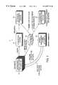
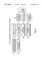
- FIG. 1is a top-level system diagram of an IP library management system according to one embodiment as disclosed herein.
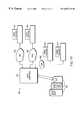
- FIG. 2is an illustration of a system architecture for an IP library management system.
- FIG. 3is an illustration of the IP library management system having a multi-tier client/server configuration.
- FIG. 4is a flowchart for an IP registration process that may be managed by the IP registration system.
- FIG. 5is a flowchart for an IP component selection process that may be managed by the IP component selection system.
- FIG. 6is a flowchart for an IP catalog database creation and update process that may be managed by the IP catalog management system.
- FIG. 7is a flowchart for a bug fixing process that may be managed by the IP modification system.
- FIG. 8is a flowchart for an initial setup and update process as may be performed by the IP data management system.
- FIG. 9is a flowchart of a release and version control application as may be managed by the IP management system.
- FIG. 10is a flowchart of a user access process as may be managed by the IP management system.
- FIG. 11is an illustration of an overview of a computer system architecture in accordance with various embodiments of the invention.
- FIG. 12is an illustration of an overview of a general architecture that may be applicable to one or more features of the various systems discussed herein.
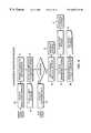
- FIG. 2is a top-level diagram of a preferred system architecture for an IP library management system in accordance with one or more embodiments as disclosed herein, details of which are illustrated in some of the other figures and/or described in the accompanying text.
- the general system architecture illustrated in FIG. 2is mapped to a 3-tier client/server database distribution system.
- an IP library management system 5connects to an IP library database 20 , which comprises an IP database 20 a and an IP catalog database 20 b , details of which are described later herein, as well as a database server.
- the IP library management system 5preferably comprises five main modules, namely an IP data management system 30 , an IP selection system 15 , an IP registration system 40 , an IP catalog management system 25 , and an IP modification system 35 . These modules are preferably embodied as platform-independent programs residing on an application server which is part of the IP library management system 5 .
- the IP database 20 acomprises a set of packaged files which are stored within a database server system.
- the database server system of the IP library database 20may comprise one or more Unix®-compatible server computer systems, thereby allowing design data within the IP database 20 a to be stored in Unix®-compatible file packages.
- the IP library database 20is preferably backed up by one or more RAID disk servers to allow availability of the information within database in case of main database system failure. Users may access the IP library database 20 via the IP library management system 5 in order to browse, select or register new or modified IPs.
- the IP library database 20 ad IP library management system 5may be implemented using any of a wide variety of computer systems and architectures.
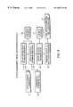
- FIG. 11illustrates an overview of a computer system architecture in accordance with various embodiments of the invention, while FIG. 12 illustrates an overview of a general architecture that may be applicable to one or more features of the various systems discussed herein.
- a computer system 620may include a host computer 622 connected to a plurality of individual user stations 624 .
- the user stations 624may each comprise suitable data terminals, for example, but not limited to, personal computers, portable laptop computers, or personal data assistants (“PDAs”), which can store and independently run one or more applications, i.e., programs.
- PDAspersonal data assistants
- LANlocal area network
- PSTNpublic telephone switched network
- the host computer 622may operate in conjunction with a data storage system 631 , wherein the data storage system 631 contains a database 632 that is readily accessible by the host computer 622 .
- the database 632may be resident on the host computer, stored, e.g., in the host computer's ROM, PROM, EPROM, or any other memory chip, and/or its hard disk.
- the database 632may be read by the host computer 622 from one or more floppy disks, flexible disks, magnetic tapes, any other magnetic medium, CD-ROMs, any other optical medium, punchcards, papertape, or any other physical medium with patterns of holes, or any other medium from which a computer can read.
- the host computer 622may access two or more databases 632 , stored in a variety of these mediums.
- each user station 624 and the host computer 622may embody a general architecture 705 .
- a processing unitmay include a bus 706 or other communication mechanism for communicating instructions, messages and data, collectively, information, and one or more processors 707 coupled with the bus 706 for processing information.
- a processing unitmay also include a main memory 708 , such as a random access memory (“RAM”) or other dynamic storage device, coupled to the bus 706 for storing dynamic data and instructions to be executed by the processor(s) 707 .
- the main memory 708also may be used for storing temporary data, i.e., variables, or other intermediate information during execution of instructions by the processor(s) 707 .
- a processing unitmay further include a read only memory (ROM) 709 or other static storage device coupled to the bus 706 for storing static data and instructions for the processor(s) 707 .
- ROMread only memory
- a storage device 710such as a magnetic disk or optical disk, may also be provided and coupled to the bus 706 for storing data and instructions for the processor(s) 707 .
- a processing unitmay be coupled via the bus 706 to a display device 711 , such as, but not limited to, a cathode ray tube (“CRT”), for displaying information to a user.
- a display device 711such as, but not limited to, a cathode ray tube (“CRT”)
- An input device 712is coupled to the bus 706 for communicating information and command selections to the processor(s) 707 .
- Another type of user input devicemay include a cursor control 713 , such as, but not limited to, a mouse, a trackball, a fingerpad, or cursor direction keys, for communicating direction information and command selections to the processor(s) 707 and for controlling cursor movement on the display 711 .
- the individual processing unitsmay perform specific operations by their respective processor(s) 707 executing one or more sequences of one or more instructions contained in the main memory 708 .
- Such instructionsmay be read into the main memory 708 from another computer-usable medium, such as the ROM 709 or the storage device 710 .
- Execution of the sequences of instructions contained in the main memory 708causes the processor(s) 707 to perform the processes described herein.
- hard-wired circuitrymay be used in place of or in combination with software instructions to implement the invention.
- Non-volatile mediai.e., media that can retain information in the absence of power
- Volatile mediai.e., media that can not retain information in the absence of power
- Transmission mediaincludes coaxial cables, copper wire and fiber optics, including the wires that comprise the bus 706 .
- Transmission mediacan also take the form of carrier waves; i.e., electromagnetic waves that can be modulated, as in frequency, amplitude or phase, to transmit information signals. Additionally, transmission media can take the form of acoustic or light waves, such as those generated during radio wave and infrared data communications.
- Computer-usable mediainclude, for example: a floppy disk, flexible disk, hard disk, magnetic tape, any other magnetic medium, CD-ROM, any other optical medium, punchcards, papertape, any other physical medium with patterns of holes, RAM, ROM, PROM (i.e., programmable read only memory), EPROM (i.e., erasable programmable read only memory), including FLASH-EPROM, any other memory chip or cartridge, carrier waves, or any other medium from which a processor 707 can retrieve information.
- a floppy diskflexible disk, hard disk, magnetic tape, any other magnetic medium, CD-ROM, any other optical medium, punchcards, papertape, any other physical medium with patterns of holes, RAM, ROM, PROM (i.e., programmable read only memory), EPROM (i.e., erasable programmable read only memory), including FLASH-EPROM, any other memory chip or cartridge, carrier waves, or any other medium from which a processor 707 can retrieve information.
- the instructionsmay initially be provided on a magnetic disk of a remote computer (not shown).
- the remote computermay load the instructions into its dynamic memory and then transit them over a telephone line, using a modem.
- a modem local to the processing unitmay receive the instructions on a telephone line and use an infrared transmitter to convert the instruction signals transmitted over the telephone line to corresponding infrared signals.
- An infrared detector(not shown) coupled to the bus 706 may receive the infrared signals and place the instructions therein on the bus 706 .
- the bus 706may carry the instructions to the main memory 708 , from which the processor(s) 707 thereafter retrieves and executes the instructions.
- the instructions received by the main memory 708may optionally be stored on the storage device 710 , either before or after their execution by the processor(s) 707 .
- Each processing unitmay also include a communication interface 714 coupled to the bus 706 .
- the communication interface 714provides two-way communication between the respective user stations 624 and the host computer 622 .
- the communication interface 714 of a respective processing unittransmits and receives electrical, electromagnetic or optical signals that include data streams representing various types of information, including instructions, messages and data.
- a communication link 715links a respective user station 624 and a host computer 622 .
- the communication link 715may be a LAN 626 , in which case the communication interface 714 may be a LAN card.
- the communication link 715may be a PSTN 628 , in which case the communication interface 714 may be an integrated services digital network (“ISDN”) card or a modem.
- ISDNintegrated services digital network
- the communication link 715may be a wireless network 630 .
- a processing unitmay transmit and receive messages, data, and instructions, including program, i.e., application, code, through its respective communication link 715 and communication interface 714 .
- Received program codemay be executed by the respective processor(s) 707 as it is received, and/or stored in the storage device 710 , or other associated non-volatile media, for later execution.
- a processing unitmay receive messages, data and/or program code in the form of a carrier wave.
- FIG. 1An example of interactions among the modules shown in FIG. 2 is illustrated in FIG. 1 .
- designers at engineering workstations 10may browse the IP database 20 to find VCs (i.e., virtual circuits) of interest by sending a query to an IP selection system 15 .
- VCsi.e., virtual circuits
- IP selection system 15An IP selection system 15 .
- a designer during such a browsewould presumably have initial interest primarily in the attributes (or metadata) of a given VC, it could be quite inefficient to search the raw IP data to locate virtual components to suit the designer's needs. Therefore, in the preferred system illustrated in FIGS.
- the raw IP datais preferably segregated into two separate databases: an IP catalog database 20 b for storing IP attributes (for example, boundary and timing properties of a given VC, or datasheet information, all of which may be generally categorized as “metadata”), and an IP database 20 a for storing the bulk of the IP data.
- IP data for a given VC stored in the IP database 20 awill usually comprise many different files, including, for example, a netlist, a layout file, and an HDL description for a given VC.
- the IP catalog database 20 bwould typically be expected (given current design sizes) to contain up to 5 kilobytes of attribute data per VC.
- the IP database 20 awould typically be expected (for current design sizes) to contain up to 300 megabytes of data per VC.
- Table 1 belowillustrates the type of data that may be packaged and stored in the IP database 20 a :
- IP Modelindicates the type of virtual component or IP
- Data Abstractindicates the file type for the particular IP model
- Softindicates the file type for the particular IP model
- Softindicates what type of form the VC data is stored in.
- the IP catalog database servermay be centralized without affecting access response time, which would generally not be possible if the metadata in the IP catalog database 20 b were not separated from the IP database 20 a .
- Most searching and browsing for IPs by a usercan be done on the IP catalog database 20 b , typically through an interactive search and browsing process.
- Various search modescan be employed, such as keyword searching, category searching, index searching or parametric searching.
- Userscan include circuit designers or architects looking for specific IP data (e.g., technical specifications of the IP), or sales or marketing personnel, third party clients, or project managers.
- IP catalog database 20 bUsers can perform a search operation on the IP catalog database 20 b through user client applications residing on their workstations 10 , and the results of any searching and browsing operations can be limited by the access rights of the user. Once the IP or group of IPs is found by a search on the IP catalog database 20 b , the user may retrieve the bulk of the corresponding IP data from the associated records in the IP database 20 a.
- each databasei.e., the IP catalog database 20 b and the IP database 20 a ) preferably has its own separate database server and disk storage subsystem.
- an IP registration system 35preferably controls the registration of new or modified IP data into the IP library database 20 , after testing that the IP data is qualified (by, for example, checking against VSIA standards or other such standards).
- the IP data management system 30 of the IP library management system 5manages a release and version control of the IP library database 20 .
- the IP data management system 30controls initial IP database setup and maintenance, and also controls user access (i.e., requires proper user authority) to the IP library database 20 .
- the IP catalog management system 25manages the IP catalog database 20 b by specifying field categories (attributes or metadata) for each VC, and by updating the IP catalog database 20 b whenever there is an addition or deletion to the IP database 20 a .
- the IP modification system 35(shown in FIG. 2) controls the tracking of “bugs” or problems associated with each VC after use or implementation.
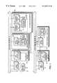
- the IP library management system 5preferably is constructed according to a three-tier client/server system architecture, an embodiment of which is illustrated in FIG. 3 .
- an IP catalog database 61 and an IP database 66are served by different file or database servers.
- the IP catalog database 61 and IP database 66may correspond to the IP catalog database 20 b and IP database 20 a of the IP library database 20 depicted in FIG. 1 .
- users at workstations 10connect to one of a plurality of local area networks (LANS) 11 and 12 .
- the LANs 11 and 12connect to one another through a wide area network 50 .
- the illustration of two-local area networks in FIG. 3is arbitrary, as the actual number of local area networks served by the IP library management system 5 may be any reasonable number, being limited essentially by the capabilities of the wide area network 50 . Because of the global reach and standardized nature of the Internet, the wide area network 50 is will be assumed to be the Internet in the following discussion, although the system would be workable with other types of wide area networks as well.
- Each local area network 11 , 12preferably has an IP interface server 55 comprising a user/interface server and data manager.
- the IP interface servers 55couple to the various data servers shown in FIG. 3 .
- each IP interface server 55regardless of which local area network 11 or 12 it resides on, couples to an IP catalog database server 60 over one of the local area networks (e.g., LAN 11 ).
- Users on LANs (e.g., LAN 12 ) other than the LAN 11 coupled to the IP catalog database server 60couple through their respective IP interface server 55 to the IP catalog database server 60 through the wide area network 50 (e.g., Internet).
- the wide area network 50e.g., Internet
- the IP catalog database server 60connects to an IP catalog database 61 (such as, for example, IP catalog database 20 b depicted in FIG. 1 ). Because of the relatively small size of the attribute data for a given VC within the IP catalog database 61 , users should experience little delay while attribute data for the VC, retrieved from the IP catalog database 61 , is transmitted over the Internet.
- IP catalog database 61such as, for example, IP catalog database 20 b depicted in FIG. 1 .
- the IP catalog database 61is preferably stored on a Redundant Array of Independent Disks (“RAID”) subsystem.
- the IP catalog database server 60preferably comprises a cluster server having a first server 62 and a second server 63 coupled to the IP catalog database 61 .
- Such a centralized locationis not necessarily desirable for the bulk of the VC data, however, because of the relatively large amount of data for a given VC, and, hence, the collectively massive amount of data for all VCs stored on the IP library database.
- Users on LANse.g., LAN 12
- other than the first LAN 11might experience considerable delay while data for a VC of interest was downloaded over the Internet.
- a master IP database server 65 on the first LAN 11couples to a master IP database 66 , which, like the IP catalog database 61 , also preferably constitutes a RAID subsystem. Users on other LANs (such as LAN 12 ) each preferably have a local IP database server 70 that couples to a local cached IP database 71 . After browsing the IP catalog database 61 and identifying a VC of interest, the bulk of the VC data is transferred from the master IP database 66 over the Internet to the local cached IP database 71 .
- the master IP database 66may contain VC data in “soft”, “firm”, or “hard” IP form as well as in any combination of these three forms.
- a “soft” IPis delivered in the form of synthesizable hardware description language (“HDL”)
- a “firm” IPhas been optimized on a library including possibly hard blocks or blocks generated by parameterized generators.
- a “hard” IPhas been optimized at the lowest level for area, power, timing, etc. and is typically delivered through a format such as GDSII.
- the data within the master IP database 66is preferably compressed or packed to save memory. Upon being transferred to a local cached IP database, the data is unpacked.
- FIG. 4a flowchart depicting an IP registration process managed by the IP registration system 40 is illustrated.
- the datamay be entered into the IP library management system.
- the userenters appropriate information in an IP registration template 80 , which may be embodied as a user interface form (UIF).
- the userplaces a request at step 81 to register the IP data.
- the IP registration system 40checks if the IP data meets IP acceptance criteria at step 82 using a stored set of IP acceptance guidelines 83 .
- IP registration system 40sends a release notice to the various affected users by sending (e.g., e-mailing) a notice 87 to these users.
- FIG. 5a process managed by the IP component selection system 15 is illustrated.
- the IP component selection system 25invokes a query engine 91 to browse through the IP catalog database for these attributes at step 92 .
- the query engineuses SQL commands to operate on an Oracle-based IP catalog database. Should this browsing step identify IP data having the required attributes, the IP component selection system requests access to the selected IP data at step 93 . This access is controlled by the IP data management system 30 through the process illustrated in FIG. 10 . If the user is permitted access, the IP component selection system copies the required IP data into the local cached IP database 71 at step 94 .
- the IP catalog database 61is created beginning at step 100 , wherein the IP data is entered into a spreadsheet.
- the IP guidelines file 101which determines what type of attributes should be attached to a given IP
- the IP catalog management systemcreates the field categories at step 102 .
- the IP guidelines file 101is as established by the VSIA.
- the field categories (or attributes)are loaded into the IP catalog database 61 .
- the IP catalog database 61is maintained by checking for duplicate data entries at step 103 .
- the IP catalogshould be modified upon the addition of IP data or modification of existing IP data by designers.
- the registration of the new or modified IP dataoccurs in the IP registration process 104 as explained with respect to FIG. 4 .
- the IP catalog management system 25then collects the IP data at step 105 and updates the IP catalog database 61 with the corresponding attributes at step 106 . Note that no reference to the IP guidelines file 101 may be made because the IP registration system 40 has already checked whether the IP data meets IP acceptance criteria (see FIG. 4 ).
- the IP registration system 40checks whether the IP data meets IP acceptance criteria, only through testing by the user (such as through emulation or simulation) can the user discover underlying problems or “bugs” in the design of a particular IP.
- FIG. 7a bug fixing or IP modification process managed by the IP modification system 35 is illustrated.
- a userinitiates a field bug report on an existing IP.
- the IP modification systemthen enters the bug report into the master IP database at step 111 and e-mails a notice 112 to the affected users.
- the IP modification system 35warns other users that this particular IP has problems.
- a request to fix the bugis sent to the designer of this particular IP at step 113 .
- a requestis made to register the resulting modified IP data at step 114 .
- the IP registration system 40registers this modified IP at step 115 as described with respect to FIG. 4, resulting in an update to the master IP database 66 and the IP catalog database 61 and a notice (e.g., an e-mail message) being sent to the affected users.
- the IP data management system 30manages the initial setup and update process of the master and local IP databases.
- FIG. 8a flow chart for this process is illustrated.
- the IP data management system 30sets up the master IP database hierarchy within the master IP database 66 using data file naming guidelines 121 . This hierarchy is necessary because of the numerous files associated with each VC. The hierarchy provides a uniform directory structure for these files. In one embodiment the data file naming guidelines 121 areas specified by the VSIA.
- the IP management system 30sets up the local IP databases 71 according to the hierarchy established in step 120 .
- the IP management system 30sends (e.g., e-mails) a notice 124 regarding the IP hierarchy to all the project managers. If new IP or modified IP is being registered at step 125 , the master IP database hierarchy is preferably altered accordingly at step 126 .
- the IP data management system 30may automatically create a new release to, for example, all the involved users of a product once a major design has been completed or a major modification has been done. This process is illustrated in FIG. 9 .
- the IP registration system 40controls the registration of new or modified IP data at step 131 .
- the IP data management system 30then preferably updates the version of the master IP database 66 at step 132 using the version control guidelines 133 . Such guidelines decide whether a modification of the database results in a new version or, instead, a new release.
- the new versionis released to users at step 134 by e-mailing a notice to all affected users at step 135 .
- the IP data management system 30synchronizes the local IP databases 71 with the IP master database 66 at step 136 .
- the IP data management system 30manages access to the databases (illustrated as a single IP database 20 for convenience) as illustrated in FIG. 10 .
- the IP data management system 30uses a user list 140 to create a user login system with password access at step 141 .
- the IP data management system 30determines whether the user has a valid password at step 144 . If the user does not, a security notice 145 is e-mailed to all the remaining users. If the user does have a valid password, the IP data management system 30 reads the permissions granted this particular user at step 146 . If the user has the required permission, access is granted to the IP database 20 .
- IPsVirtual Components
- knowledge-warei.e., design guidelines and methodologies
Landscapes
- Engineering & Computer Science (AREA)
- Theoretical Computer Science (AREA)
- Business, Economics & Management (AREA)
- Physics & Mathematics (AREA)
- General Physics & Mathematics (AREA)
- Entrepreneurship & Innovation (AREA)
- Human Resources & Organizations (AREA)
- Strategic Management (AREA)
- General Business, Economics & Management (AREA)
- Finance (AREA)
- Computer Hardware Design (AREA)
- Operations Research (AREA)
- Marketing (AREA)
- Economics (AREA)
- Data Mining & Analysis (AREA)
- Accounting & Taxation (AREA)
- Development Economics (AREA)
- General Engineering & Computer Science (AREA)
- Databases & Information Systems (AREA)
- Technology Law (AREA)
- Computing Systems (AREA)
- Game Theory and Decision Science (AREA)
- Quality & Reliability (AREA)
- Tourism & Hospitality (AREA)
- Evolutionary Computation (AREA)
- Geometry (AREA)
- Information Retrieval, Db Structures And Fs Structures Therefor (AREA)
Abstract
Description
| TABLE 1 | ||||
| IP Model | Data Abstract | Soft | Firm | Hard |
| Functional Model | Verilog RTL | X | X | X |
| Bus Functional Model | Verilog RTL | X | X | X |
| Synthesis Constraints | Synopsys Scripts, | X | X | |
| ASCII | ||||
| Floor-Plan Wiring | PDEF, DEF | X | ||
| Constraints | ||||
| Floor-Plan Placement | PDEF, DEF | X | ||
| Constraints | ||||
| IP Block Pin Attributes | LEF, ASCII (clock, | X | ||
| power, test pins) | ||||
| Timing Characteristics | Synopsys NLDM, TLF | X | X | |
| Manufacturing Test Vectors | Verilog, WGL | X | X | X |
| Functional Test Bench | Verilog | X | X | X |
| Layout | Abstract, GDSII | X | ||
| Spice Netlist | Spice | X | ||
| Gate-Level Netlist | Verilog | X | X | X |
| Power Model | TBD | X | X | X |
| Embedded software | Source Data, | |||
| executables | ||||
Claims (6)
Priority Applications (6)
| Application Number | Priority Date | Filing Date | Title |
|---|---|---|---|
| US09/467,563US6687710B1 (en) | 1999-12-03 | 1999-12-20 | Intellectual property library management system |
| AU45079/01AAU4507901A (en) | 1999-12-03 | 2000-11-28 | Ip library management system |
| EP00992527AEP1259893A2 (en) | 1999-12-03 | 2000-11-28 | Ip library management system |
| PCT/US2000/042299WO2001042969A2 (en) | 1999-12-03 | 2000-11-28 | Ip library management system |
| TW089125499ATW469382B (en) | 1999-12-03 | 2001-03-01 | IP library management system |
| US10/622,379US6970875B1 (en) | 1999-12-03 | 2003-07-18 | IP library management system |
Applications Claiming Priority (2)
| Application Number | Priority Date | Filing Date | Title |
|---|---|---|---|
| US45602299A | 1999-12-03 | 1999-12-03 | |
| US09/467,563US6687710B1 (en) | 1999-12-03 | 1999-12-20 | Intellectual property library management system |
Related Parent Applications (1)
| Application Number | Title | Priority Date | Filing Date |
|---|---|---|---|
| US45602299AContinuation-In-Part | 1999-12-03 | 1999-12-03 |
Related Child Applications (1)
| Application Number | Title | Priority Date | Filing Date |
|---|---|---|---|
| US10/622,379ContinuationUS6970875B1 (en) | 1999-12-03 | 2003-07-18 | IP library management system |
Publications (1)
| Publication Number | Publication Date |
|---|---|
| US6687710B1true US6687710B1 (en) | 2004-02-03 |
Family
ID=30444227
Family Applications (1)
| Application Number | Title | Priority Date | Filing Date |
|---|---|---|---|
| US09/467,563Expired - LifetimeUS6687710B1 (en) | 1999-12-03 | 1999-12-20 | Intellectual property library management system |
Country Status (1)
| Country | Link |
|---|---|
| US (1) | US6687710B1 (en) |
Cited By (57)
| Publication number | Priority date | Publication date | Assignee | Title |
|---|---|---|---|---|
| US20020059053A1 (en)* | 2000-11-15 | 2002-05-16 | Yohei Akita | System verification equipment, system verification method and LSI manufacturing method using the system verification equipment |
| US20030074362A1 (en)* | 1999-07-26 | 2003-04-17 | Microsoft Corporation | Catalog management system architecture having data table objects and logic table objects |
| US20030191869A1 (en)* | 2002-04-04 | 2003-10-09 | International Business Machines Corp. | C-API instrumentation for HDL models |
| US20030191617A1 (en)* | 2002-04-04 | 2003-10-09 | Gabele Carol Ivash | Method and system for selectively storing and retrieving simulation data utilizing keywords |
| US20030191621A1 (en)* | 2002-04-04 | 2003-10-09 | International Business Machines Corporation | Method and system for reducing storage and transmission requirements for simulation results |
| US20040107085A1 (en)* | 2002-11-18 | 2004-06-03 | Vpisystems Pte | Simulation player |
| US20040148232A1 (en)* | 2001-01-22 | 2004-07-29 | Osamu Fushimi | Electronic catalog aggregation apparatus for realizing fast and efficient electronic catalog system |
| US20040144798A1 (en)* | 2001-02-23 | 2004-07-29 | Tianhong Ouyang | Dosage counting devices |
| US20040149772A1 (en)* | 2001-02-23 | 2004-08-05 | Tianhong Ouyang | Dosage counting devices |
| US20040149773A1 (en)* | 2001-02-23 | 2004-08-05 | Tianhong Ouyang | Dosage counting devices |
| US20040210854A1 (en)* | 2001-12-10 | 2004-10-21 | Mentor Graphics Corporation | Parellel electronic design automation: shared simultaneous editing |
| US20050044518A1 (en)* | 2001-12-10 | 2005-02-24 | Mentor Graphics Corporation | Reservation of design elements in a parallel printed circuit board design environment |
| US20050063524A1 (en)* | 2002-12-11 | 2005-03-24 | Leader Technologies, Inc. | Communication system and method |
| US20050114865A1 (en)* | 2003-11-21 | 2005-05-26 | Mentor Graphics Corporation | Integrating multiple electronic design applications |
| US20050114821A1 (en)* | 2003-11-21 | 2005-05-26 | Mentor Graphics Corporation | Distributed autorouting of conductive paths |
| US20050149313A1 (en)* | 2003-12-31 | 2005-07-07 | International Business Machines Corp. | Method and system for selective compilation of instrumentation entities into a simulation model of a digital design |
| US6970814B1 (en)* | 2000-03-30 | 2005-11-29 | International Business Machines Corporation | Remote IP simulation modeling |
| US6970875B1 (en)* | 1999-12-03 | 2005-11-29 | Synchronicity Software, Inc. | IP library management system |
| US20060085314A1 (en)* | 2004-10-14 | 2006-04-20 | Grim Clifton E Iii | Escrowing digital property in a secure information vault |
| US20060089827A1 (en)* | 2004-10-21 | 2006-04-27 | International Business Machines Corporation | Method, system and program product for defining and recording minium and maximum event counts of a simulation utilizing a high level language |
| US20060089826A1 (en)* | 2004-10-21 | 2006-04-27 | International Business Machines Corporation | Method, system and program product for defining and recording minimum and maximum count events of a simulation |
| US20060095882A1 (en)* | 2004-09-08 | 2006-05-04 | Mentor Graphics Corporation | Distributed electronic design automation environment |
| US20060101368A1 (en)* | 2004-09-08 | 2006-05-11 | Mentor Graphics Corporation | Distributed electronic design automation environment |
| US20060123370A1 (en)* | 2004-12-08 | 2006-06-08 | Mario Vergara-Escobar | Method for specification and integration of reusable IP constraints |
| US20060122818A1 (en)* | 2004-12-07 | 2006-06-08 | International Business Machines Corporation | Method, system and program product for defining and recording threshold-qualified count events of a simulation by testcases |
| US20060190111A1 (en)* | 2005-02-03 | 2006-08-24 | Wang Beniz | System and method of designing a product or a module therein based on experiences of modular designs accumulated previously |
| US20070061121A1 (en)* | 2005-09-15 | 2007-03-15 | Gabor Bobok | Method, system and program product for selectively removing instrumentation logic from a simulation model |
| US20070106708A1 (en)* | 2005-10-26 | 2007-05-10 | Dana Rigg | Managing hierarchies of components |
| US20070127400A1 (en)* | 2002-12-11 | 2007-06-07 | Leader Technologies, Inc. | Professional Services Communications Architecture |
| US20070185898A1 (en)* | 2006-02-08 | 2007-08-09 | International Business Machines Corporation | Dynamic schema-based silicon IP analysis, qualification, data exchange, and integration |
| US20070260441A1 (en)* | 2006-05-08 | 2007-11-08 | Gabor Bobok | Method, system and program product supporting phase events in a simulation model of a digital system |
| US20070260443A1 (en)* | 2006-05-03 | 2007-11-08 | Gabor Bobok | Method, system and program product supporting specification of signals for simulation result viewing |
| US7337174B1 (en) | 1999-07-26 | 2008-02-26 | Microsoft Corporation | Logic table abstraction layer for accessing configuration information |
| US7373290B2 (en) | 2002-04-04 | 2008-05-13 | International Business Machines Corporation | Method and system for reducing storage requirements of simulation data via keyword restrictions |
| US20080183458A1 (en)* | 2007-01-30 | 2008-07-31 | Gabor Bobok | Method, system and program product supporting print events in the simulation of a digital system |
| CN100424708C (en)* | 2005-03-24 | 2008-10-08 | 英业达股份有限公司 | System with accumulated modular design experience and method thereof |
| US20090112561A1 (en)* | 2007-10-31 | 2009-04-30 | Behm Michael L | Method, System and Program Product for Defining and Recording Threshold-Qualified Count Events of a Simulation By Testcases |
| US7536288B2 (en) | 2003-12-31 | 2009-05-19 | International Business Machines Corporation | Method, system and program product supporting user tracing in a simulator |
| US20090177635A1 (en)* | 2008-01-08 | 2009-07-09 | Protecode Incorporated | System and Method to Automatically Enhance Confidence in Intellectual Property Ownership |
| US7577726B1 (en)* | 2002-02-07 | 2009-08-18 | Cisco Technology, Inc. | Method for updating a hardware configuration of a networked communications device |
| US7587695B2 (en) | 2001-12-10 | 2009-09-08 | Mentor Graphics Corporation | Protection boundaries in a parallel printed circuit board design environment |
| US20100153898A1 (en)* | 2008-12-16 | 2010-06-17 | International Business Machines Corporation | Model build in the presence of a non-binding reference |
| US20100161509A1 (en)* | 2008-12-24 | 2010-06-24 | Industrial Technology Research Institute | Intellectual property management method and intellectual property bank system |
| US7925246B2 (en) | 2002-12-11 | 2011-04-12 | Leader Technologies, Inc. | Radio/telephony interoperability system |
| US20110202935A1 (en)* | 2000-03-01 | 2011-08-18 | Webs, Inc. | System and method for providing a web-based operating system |
| US8050902B2 (en) | 2007-10-31 | 2011-11-01 | International Business Machines Corporation | Reporting temporal information regarding count events of a simulation |
| US8160857B2 (en) | 2008-12-16 | 2012-04-17 | International Business Machines Corporation | Selective compilation of a simulation model in view of unavailable higher level signals |
| US20120095849A1 (en)* | 2000-03-03 | 2012-04-19 | Berger Martin S | System and method for promoting intellectual property |
| US8195714B2 (en) | 2002-12-11 | 2012-06-05 | Leaper Technologies, Inc. | Context instantiated application protocol |
| US8326926B2 (en) | 2005-09-13 | 2012-12-04 | Mentor Graphics Corporation | Distributed electronic design automation architecture |
| US8522180B1 (en)* | 2012-06-27 | 2013-08-27 | Cadence Design Systems, Inc. | Method and system identifying IP blocks and block suppliers for an electronic design |
| US8538848B1 (en) | 2005-07-29 | 2013-09-17 | IVP Holdings I, LLC | Revenue allocation for bundled intellectual property transactions |
| US9310433B2 (en) | 2014-04-18 | 2016-04-12 | Breker Verification Systems | Testing SOC with portable scenario models and at different levels |
| US9881117B1 (en)* | 2016-07-07 | 2018-01-30 | Xilinx, Inc. | Predictive circuit design for integrated circuits |
| US20190188350A1 (en)* | 2017-12-18 | 2019-06-20 | Texas Instruments Incorporated | System and method for interactive datasheets |
| US10635766B2 (en) | 2016-12-12 | 2020-04-28 | International Business Machines Corporation | Simulation employing level-dependent multitype events |
| US12438727B1 (en) | 2021-03-24 | 2025-10-07 | International Business Machines Corporation | Tracing and verifying a shared library using blockchain |
Citations (10)
| Publication number | Priority date | Publication date | Assignee | Title |
|---|---|---|---|---|
| US5418954A (en) | 1991-06-19 | 1995-05-23 | Cadence Design Systems, Inc. | Method for preparing and dynamically loading context files |
| WO1995021416A1 (en) | 1994-02-04 | 1995-08-10 | Cadence Design Systems Inc | Distributed file system providing transparent data management |
| WO1997022074A1 (en) | 1995-12-11 | 1997-06-19 | Cybergold, Inc. | Method for trading customer attention for advertisement |
| WO1997046950A1 (en) | 1996-06-04 | 1997-12-11 | Multex Systems, Inc. | Information delivery system and method |
| US5933498A (en) | 1996-01-11 | 1999-08-03 | Mrj, Inc. | System for controlling access and distribution of digital property |
| US6006332A (en)* | 1996-10-21 | 1999-12-21 | Case Western Reserve University | Rights management system for digital media |
| US6157947A (en) | 1998-02-09 | 2000-12-05 | Fujitsu Limited | Method, apparatus, system, and program storage device for distributing intellectual property |
| WO2001042969A2 (en) | 1999-12-03 | 2001-06-14 | Synchronicity, Software, Inc. | Ip library management system |
| US20020002524A1 (en)* | 1999-03-17 | 2002-01-03 | Nir Kossovsky | Online patent and license exchange |
| US20020019836A1 (en)* | 2000-05-16 | 2002-02-14 | Hirokazu Uchio | Information processing apparatus for management of documents relevant to patent application |
- 1999
- 1999-12-20USUS09/467,563patent/US6687710B1/ennot_activeExpired - Lifetime
Patent Citations (12)
| Publication number | Priority date | Publication date | Assignee | Title |
|---|---|---|---|---|
| US5418954A (en) | 1991-06-19 | 1995-05-23 | Cadence Design Systems, Inc. | Method for preparing and dynamically loading context files |
| WO1995021416A1 (en) | 1994-02-04 | 1995-08-10 | Cadence Design Systems Inc | Distributed file system providing transparent data management |
| WO1997022074A1 (en) | 1995-12-11 | 1997-06-19 | Cybergold, Inc. | Method for trading customer attention for advertisement |
| US5794210A (en) | 1995-12-11 | 1998-08-11 | Cybergold, Inc. | Attention brokerage |
| US5855008A (en) | 1995-12-11 | 1998-12-29 | Cybergold, Inc. | Attention brokerage |
| US5933498A (en) | 1996-01-11 | 1999-08-03 | Mrj, Inc. | System for controlling access and distribution of digital property |
| WO1997046950A1 (en) | 1996-06-04 | 1997-12-11 | Multex Systems, Inc. | Information delivery system and method |
| US6006332A (en)* | 1996-10-21 | 1999-12-21 | Case Western Reserve University | Rights management system for digital media |
| US6157947A (en) | 1998-02-09 | 2000-12-05 | Fujitsu Limited | Method, apparatus, system, and program storage device for distributing intellectual property |
| US20020002524A1 (en)* | 1999-03-17 | 2002-01-03 | Nir Kossovsky | Online patent and license exchange |
| WO2001042969A2 (en) | 1999-12-03 | 2001-06-14 | Synchronicity, Software, Inc. | Ip library management system |
| US20020019836A1 (en)* | 2000-05-16 | 2002-02-14 | Hirokazu Uchio | Information processing apparatus for management of documents relevant to patent application |
Non-Patent Citations (22)
| Title |
|---|
| Allen et al., "the MCC CAD Framework Methodology Managment System," 1991 ACM/IEEE Design Automation Conference, vol. 40.1, pp. 694-698, (1991). |
| Alles et al., "Taking a Look at Internet-Based Design in the Year 2001," Electronic Design, pp. 42-50, (1997). |
| Claretto et al., "Fast Prototyping of an ASIC for ATM Application Using a Synthesizable VHDL Flexible Library," VHDL International Users'Forum Fall Conference, pp. 88-94, (1997). |
| Coors, et al., "Hardware/Software Co-Design for IP Objects Based on CORBA," IEEE Fall 1999 VIUF Workshop, pp. 63-68 (1999), XP-010358555. |
| Cottrell, "Electronic Component Information Exchange" 1997 Design Automation Conference Proceedings, vol. 35.2, pp. 559-563, (1997). |
| Dunlop et al., "OMI-A Standard Model Interface for IP Delivery," 1997 IEEE International Verilog HDL Conference, pp. 83-90, (1997). |
| Engel et al., "Design methodology for IBM ASIC products," IBM. J. RES. DEVELOP., vol. 40 No. 4, pp. 387-405, (Jul. 1996). |
| Fujii, "Internet-driven IP highway has started," Nikkei Microdevices, pp. 66-68 (Jul. 1997) (Japanese with English translation). |
| Glaser, "Change is coming: PCB-like paradigm shift only path to system chips,"60 Electronic Engineering, pp. 44-45, (Apr. 1997). |
| Goering et al., "Web-based design hoists new sail" Retrieved from the Internet: http://www.eetimes.com/news/97/959news/webbased.html (Jun. 16, 1997) (retrieved on Jul. 31, 2001). |
| Hokosaki et al., "IP Highway Sharing Design Information on System LSI Device," Retrieved from the Internet: http://salesgroup.fujitsu.com/journal/236e/e36tkl-9.html, 4 pages, (retrieved on Aug. 8, 2001). |
| Jeffery et al., "The Pinnacles Electronic Component Information Exchange Project," Retrieved from the Internet: http://xml.coverpages.org/ecix-techwrite.htm1, pp. 1-11, (Jan. 19, 1996) (retrieved on Feb. 15,2002). |
| Karam et al., "CAD and Foundries for Microsystems," Proceedings 1997 Design Automation Conference, pp. 674-679, (1997). |
| Marell, "Intellectual Property for the Engineer, Purchaser and Seller," Wescon/97 Conference Proceedings, pp. 576-581, (Nov. 4-6, 1997). |
| Olcoz, et al., "Improving VHDL Soft-Cores Reuse with Software-like Reviews and Adults Procedures," 1998 IEEE Verilog HDL Conference and VHDL International Users Forum, pp. 143-146, (1998), XP010270983. |
| Schindler, et al., "IP Repository, a Web Based IP Reuse Infrastructure," IEEE 1999 Custom Integrated Circuits Conference, pp. 415-418 (1999), XP-010340679. |
| Schürmann et al., "Modeling Design Tasks and Tools-the Link Between Product and Flow Model," 1997 Design Automation Conference Proceedings, 6 pages, (1997). |
| Spiller et al., "EDA and the Network," IEEE/ACM International Conference on Computer Aided Design, 7 pages, (1997). |
| Svoboda, "IP Tames Today's DSP Design Challenges," Electronic Design, pp. 99-108, (1996). |
| Tschichholz et al., "Management of a Secure WWW-Based Document Store," ISADS 97-Third International Symposium on Autonomous Decentralized Systems, pp. 291-298, (1997). |
| Ussery et al., "IP evaluation using interactive datasheets," Electronic Engineering, pp. 33-38, (1997). |
| Van de Riet et al., "An Object-Oriented Database Architecture for providing Security in Cyberspace," IFIP TC11/WG11.3 Tenth International Conference on Database Security, pp. 121-144, (Jul. 22-24, 1996). |
Cited By (96)
| Publication number | Priority date | Publication date | Assignee | Title |
|---|---|---|---|---|
| US20050177566A1 (en)* | 1999-07-26 | 2005-08-11 | Microsoft Corporation | Catalog management system architecture having data table objects and logic table objects |
| US6917933B2 (en)* | 1999-07-26 | 2005-07-12 | Microsoft Corporation | Catalog management system architecture having data table objects and logic table objects |
| US7620617B2 (en) | 1999-07-26 | 2009-11-17 | Microsoft Corporation | Abstraction layer for presenting configuration information to a caller |
| US20030074362A1 (en)* | 1999-07-26 | 2003-04-17 | Microsoft Corporation | Catalog management system architecture having data table objects and logic table objects |
| US7337174B1 (en) | 1999-07-26 | 2008-02-26 | Microsoft Corporation | Logic table abstraction layer for accessing configuration information |
| US6970875B1 (en)* | 1999-12-03 | 2005-11-29 | Synchronicity Software, Inc. | IP library management system |
| US20110202935A1 (en)* | 2000-03-01 | 2011-08-18 | Webs, Inc. | System and method for providing a web-based operating system |
| US8447832B2 (en)* | 2000-03-01 | 2013-05-21 | Rpx Corporation | System and method for providing a web-based operating system |
| US8752037B2 (en)* | 2000-03-03 | 2014-06-10 | Martin S. Berger | System and method for promoting intellectual property |
| US20120095849A1 (en)* | 2000-03-03 | 2012-04-19 | Berger Martin S | System and method for promoting intellectual property |
| US6970814B1 (en)* | 2000-03-30 | 2005-11-29 | International Business Machines Corporation | Remote IP simulation modeling |
| US7039576B2 (en)* | 2000-11-15 | 2006-05-02 | Renesas Technology Corporation | System verification equipment, system verification method and LSI manufacturing method using the system verification equipment |
| US20020059053A1 (en)* | 2000-11-15 | 2002-05-16 | Yohei Akita | System verification equipment, system verification method and LSI manufacturing method using the system verification equipment |
| US20040148232A1 (en)* | 2001-01-22 | 2004-07-29 | Osamu Fushimi | Electronic catalog aggregation apparatus for realizing fast and efficient electronic catalog system |
| US20040149773A1 (en)* | 2001-02-23 | 2004-08-05 | Tianhong Ouyang | Dosage counting devices |
| US20040149772A1 (en)* | 2001-02-23 | 2004-08-05 | Tianhong Ouyang | Dosage counting devices |
| US20040144798A1 (en)* | 2001-02-23 | 2004-07-29 | Tianhong Ouyang | Dosage counting devices |
| US20040210854A1 (en)* | 2001-12-10 | 2004-10-21 | Mentor Graphics Corporation | Parellel electronic design automation: shared simultaneous editing |
| US7587695B2 (en) | 2001-12-10 | 2009-09-08 | Mentor Graphics Corporation | Protection boundaries in a parallel printed circuit board design environment |
| US7516435B2 (en) | 2001-12-10 | 2009-04-07 | Mentor Graphics Corporation | Reservation of design elements in a parallel printed circuit board design environment |
| US20100199240A1 (en)* | 2001-12-10 | 2010-08-05 | Mentor Graphics Corporation | Parallel Electronic Design Automation: Shared Simultaneous Editing |
| US20080059932A1 (en)* | 2001-12-10 | 2008-03-06 | Mentor Graphics Corporation | Parallel Electronic Design Automation: Shared Simultaneous Editing |
| US7949990B2 (en) | 2001-12-10 | 2011-05-24 | Mentor Graphics Corporation | Parallel electronic design automation: shared simultaneous editing |
| US20050044518A1 (en)* | 2001-12-10 | 2005-02-24 | Mentor Graphics Corporation | Reservation of design elements in a parallel printed circuit board design environment |
| US7577726B1 (en)* | 2002-02-07 | 2009-08-18 | Cisco Technology, Inc. | Method for updating a hardware configuration of a networked communications device |
| US20030191617A1 (en)* | 2002-04-04 | 2003-10-09 | Gabele Carol Ivash | Method and system for selectively storing and retrieving simulation data utilizing keywords |
| US7373290B2 (en) | 2002-04-04 | 2008-05-13 | International Business Machines Corporation | Method and system for reducing storage requirements of simulation data via keyword restrictions |
| US7194400B2 (en)* | 2002-04-04 | 2007-03-20 | International Business Machines Corporation | Method and system for reducing storage and transmission requirements for simulation results |
| US7203633B2 (en) | 2002-04-04 | 2007-04-10 | International Business Machines Corporation | Method and system for selectively storing and retrieving simulation data utilizing keywords |
| US7206732B2 (en) | 2002-04-04 | 2007-04-17 | International Business Machines Corporation | C-API instrumentation for HDL models |
| US20030191621A1 (en)* | 2002-04-04 | 2003-10-09 | International Business Machines Corporation | Method and system for reducing storage and transmission requirements for simulation results |
| US20030191869A1 (en)* | 2002-04-04 | 2003-10-09 | International Business Machines Corp. | C-API instrumentation for HDL models |
| US7451069B2 (en)* | 2002-11-18 | 2008-11-11 | Vpisystems Inc. | Simulation player |
| US20040107085A1 (en)* | 2002-11-18 | 2004-06-03 | Vpisystems Pte | Simulation player |
| US7925246B2 (en) | 2002-12-11 | 2011-04-12 | Leader Technologies, Inc. | Radio/telephony interoperability system |
| US20050063524A1 (en)* | 2002-12-11 | 2005-03-24 | Leader Technologies, Inc. | Communication system and method |
| US8195714B2 (en) | 2002-12-11 | 2012-06-05 | Leaper Technologies, Inc. | Context instantiated application protocol |
| US20070127400A1 (en)* | 2002-12-11 | 2007-06-07 | Leader Technologies, Inc. | Professional Services Communications Architecture |
| US20050114821A1 (en)* | 2003-11-21 | 2005-05-26 | Mentor Graphics Corporation | Distributed autorouting of conductive paths |
| US7305648B2 (en) | 2003-11-21 | 2007-12-04 | Mentor Graphics Corporation | Distributed autorouting of conductive paths in printed circuit boards |
| US20080034342A1 (en)* | 2003-11-21 | 2008-02-07 | Mentor Graphics Corporation | Distributed Autorouting of Conductive Paths |
| US20050114865A1 (en)* | 2003-11-21 | 2005-05-26 | Mentor Graphics Corporation | Integrating multiple electronic design applications |
| US7590963B2 (en) | 2003-11-21 | 2009-09-15 | Mentor Graphics Corporation | Integrating multiple electronic design applications |
| US7788622B2 (en) | 2003-11-21 | 2010-08-31 | Mentor Graphics Corporation | Distributed autorouting of conductive paths |
| US7236918B2 (en) | 2003-12-31 | 2007-06-26 | International Business Machines Corporation | Method and system for selective compilation of instrumentation entities into a simulation model of a digital design |
| US7536288B2 (en) | 2003-12-31 | 2009-05-19 | International Business Machines Corporation | Method, system and program product supporting user tracing in a simulator |
| US20050149313A1 (en)* | 2003-12-31 | 2005-07-07 | International Business Machines Corp. | Method and system for selective compilation of instrumentation entities into a simulation model of a digital design |
| US20060095882A1 (en)* | 2004-09-08 | 2006-05-04 | Mentor Graphics Corporation | Distributed electronic design automation environment |
| US20060101368A1 (en)* | 2004-09-08 | 2006-05-11 | Mentor Graphics Corporation | Distributed electronic design automation environment |
| US7546571B2 (en) | 2004-09-08 | 2009-06-09 | Mentor Graphics Corporation | Distributed electronic design automation environment |
| US20060085314A1 (en)* | 2004-10-14 | 2006-04-20 | Grim Clifton E Iii | Escrowing digital property in a secure information vault |
| US8606673B1 (en) | 2004-10-14 | 2013-12-10 | Google Inc. | Escrowing digital property in a secure information vault |
| US8224725B2 (en)* | 2004-10-14 | 2012-07-17 | Google Inc. | Escrowing digital property in a secure information vault |
| US20060089826A1 (en)* | 2004-10-21 | 2006-04-27 | International Business Machines Corporation | Method, system and program product for defining and recording minimum and maximum count events of a simulation |
| US20060089827A1 (en)* | 2004-10-21 | 2006-04-27 | International Business Machines Corporation | Method, system and program product for defining and recording minium and maximum event counts of a simulation utilizing a high level language |
| US7392169B2 (en) | 2004-10-21 | 2008-06-24 | International Business Machines Corporation | Method, system and program product for defining and recording minimum and maximum event counts of a simulation utilizing a high level language |
| US7454325B2 (en) | 2004-12-07 | 2008-11-18 | International Business Machines Corporation | Method, system and program product for defining and recording threshold-qualified count events of a simulation by testcases |
| US20060122818A1 (en)* | 2004-12-07 | 2006-06-08 | International Business Machines Corporation | Method, system and program product for defining and recording threshold-qualified count events of a simulation by testcases |
| US7526745B2 (en) | 2004-12-08 | 2009-04-28 | Telefonaktiebolaget L M Ericsson (Publ) | Method for specification and integration of reusable IP constraints |
| US20060123370A1 (en)* | 2004-12-08 | 2006-06-08 | Mario Vergara-Escobar | Method for specification and integration of reusable IP constraints |
| US20060190111A1 (en)* | 2005-02-03 | 2006-08-24 | Wang Beniz | System and method of designing a product or a module therein based on experiences of modular designs accumulated previously |
| CN100424708C (en)* | 2005-03-24 | 2008-10-08 | 英业达股份有限公司 | System with accumulated modular design experience and method thereof |
| US8538848B1 (en) | 2005-07-29 | 2013-09-17 | IVP Holdings I, LLC | Revenue allocation for bundled intellectual property transactions |
| US8326926B2 (en) | 2005-09-13 | 2012-12-04 | Mentor Graphics Corporation | Distributed electronic design automation architecture |
| US7552043B2 (en) | 2005-09-15 | 2009-06-23 | International Business Machines Corporation | Method, system and program product for selectively removing instrumentation logic from a simulation model |
| US20070061121A1 (en)* | 2005-09-15 | 2007-03-15 | Gabor Bobok | Method, system and program product for selectively removing instrumentation logic from a simulation model |
| US20070106708A1 (en)* | 2005-10-26 | 2007-05-10 | Dana Rigg | Managing hierarchies of components |
| US8521736B2 (en) | 2005-10-26 | 2013-08-27 | Dassault Systemes Enovia Corp. | Managing hierarchies of components |
| US7571184B2 (en)* | 2006-02-08 | 2009-08-04 | International Business Machines Corporation | Dynamic schema-based silicon IP analysis, qualification, data exchange, and integration |
| US20070185898A1 (en)* | 2006-02-08 | 2007-08-09 | International Business Machines Corporation | Dynamic schema-based silicon IP analysis, qualification, data exchange, and integration |
| US7711537B2 (en) | 2006-05-03 | 2010-05-04 | International Business Machines Corporation | Signals for simulation result viewing |
| US20070260443A1 (en)* | 2006-05-03 | 2007-11-08 | Gabor Bobok | Method, system and program product supporting specification of signals for simulation result viewing |
| US20070260441A1 (en)* | 2006-05-08 | 2007-11-08 | Gabor Bobok | Method, system and program product supporting phase events in a simulation model of a digital system |
| US7493248B2 (en) | 2006-05-08 | 2009-02-17 | International Business Machines Corporation | Method, system and program product supporting phase events in a simulation model of a digital system |
| US20080183458A1 (en)* | 2007-01-30 | 2008-07-31 | Gabor Bobok | Method, system and program product supporting print events in the simulation of a digital system |
| US7912694B2 (en) | 2007-01-30 | 2011-03-22 | International Business Machines Corporation | Print events in the simulation of a digital system |
| US20090112561A1 (en)* | 2007-10-31 | 2009-04-30 | Behm Michael L | Method, System and Program Product for Defining and Recording Threshold-Qualified Count Events of a Simulation By Testcases |
| US8050902B2 (en) | 2007-10-31 | 2011-11-01 | International Business Machines Corporation | Reporting temporal information regarding count events of a simulation |
| US7925489B2 (en) | 2007-10-31 | 2011-04-12 | International Business Machines Corporation | Defining and recording threshold-qualified count events of a simulation by testcases |
| US20090177635A1 (en)* | 2008-01-08 | 2009-07-09 | Protecode Incorporated | System and Method to Automatically Enhance Confidence in Intellectual Property Ownership |
| US8160857B2 (en) | 2008-12-16 | 2012-04-17 | International Business Machines Corporation | Selective compilation of a simulation model in view of unavailable higher level signals |
| US8453080B2 (en) | 2008-12-16 | 2013-05-28 | International Business Machines Corporation | Model build in the presence of a non-binding reference |
| US20100153898A1 (en)* | 2008-12-16 | 2010-06-17 | International Business Machines Corporation | Model build in the presence of a non-binding reference |
| US20100161509A1 (en)* | 2008-12-24 | 2010-06-24 | Industrial Technology Research Institute | Intellectual property management method and intellectual property bank system |
| US8522180B1 (en)* | 2012-06-27 | 2013-08-27 | Cadence Design Systems, Inc. | Method and system identifying IP blocks and block suppliers for an electronic design |
| US9310433B2 (en) | 2014-04-18 | 2016-04-12 | Breker Verification Systems | Testing SOC with portable scenario models and at different levels |
| US9316689B2 (en) | 2014-04-18 | 2016-04-19 | Breker Verification Systems | Scheduling of scenario models for execution within different computer threads and scheduling of memory regions for use with the scenario models |
| US9360523B2 (en) | 2014-04-18 | 2016-06-07 | Breker Verification Systems | Display in a graphical format of test results generated using scenario models |
| US10365326B2 (en) | 2014-04-18 | 2019-07-30 | Breker Verification Systems | Scheduling of scenario models for execution within different computer threads and scheduling of memory regions for use with the scenario models |
| US11113184B2 (en)* | 2014-04-18 | 2021-09-07 | Breker Verification Systems | Display in a graphical format of test results generated using scenario models |
| US9881117B1 (en)* | 2016-07-07 | 2018-01-30 | Xilinx, Inc. | Predictive circuit design for integrated circuits |
| US10635766B2 (en) | 2016-12-12 | 2020-04-28 | International Business Machines Corporation | Simulation employing level-dependent multitype events |
| US20190188350A1 (en)* | 2017-12-18 | 2019-06-20 | Texas Instruments Incorporated | System and method for interactive datasheets |
| US10521540B2 (en)* | 2017-12-18 | 2019-12-31 | Texas Instruments Incorporated | System and method for interactive datasheets |
| US11023643B2 (en) | 2017-12-18 | 2021-06-01 | Texas Instruments Incorporated | System and method for interactive datasheets |
| US12438727B1 (en) | 2021-03-24 | 2025-10-07 | International Business Machines Corporation | Tracing and verifying a shared library using blockchain |
Similar Documents
| Publication | Publication Date | Title |
|---|---|---|
| US6687710B1 (en) | Intellectual property library management system | |
| US6970875B1 (en) | IP library management system | |
| US6484177B1 (en) | Data management interoperability methods for heterogeneous directory structures | |
| Baru et al. | The SDSC storage resource broker | |
| US5724556A (en) | Method and apparatus for defining and configuring modules of data objects and programs in a distributed computer system | |
| US6961918B2 (en) | System for intellectual property reuse in integrated circuit design | |
| US6327594B1 (en) | Methods for shared data management in a pervasive computing environment | |
| CN101676920B (en) | Method and apparatus for merging EDA coverage logs of coverage data | |
| US8260813B2 (en) | Flexible data archival using a model-driven approach | |
| US5856925A (en) | Method for making electronic circuit design data and CAD system using the method | |
| US6223345B1 (en) | System and method for building client and server application packages | |
| US20080168057A1 (en) | Method and system for reducing storage requirements of simulation data via keyword restrictions | |
| GB2321324A (en) | Data management for concurrent engineering | |
| Dong et al. | Managing design information in enterprise-wide CAD usingsmart drawings' | |
| WO2001042969A2 (en) | Ip library management system | |
| US8645321B1 (en) | Asynchronous data integrity for enterprise computing | |
| US20090055518A1 (en) | Method and apparatus for managing lightweight directory access protocol information | |
| Sunderic et al. | Stored Procedure Programming | |
| Chen et al. | Transaction-based grid database replication | |
| Wade | Hitting the relational Wall | |
| No et al. | GEDAS: A data management system for data grid environments | |
| Karinathi et al. | Modeling enterprise information and enabling access using information sharing server | |
| Decker et al. | Wide-area replication support for global data repositories | |
| Litvintsev et al. | Enstore with Chimera namespace provider | |
| Mills et al. | INFEO Search-A |
Legal Events
| Date | Code | Title | Description |
|---|---|---|---|
| AS | Assignment | Owner name:CADENCE DESIGN SYSTEMS INC., CALIFORNIA Free format text:ASSIGNMENT OF ASSIGNORS INTEREST;ASSIGNOR:DEY, APARNA;REEL/FRAME:010713/0095 Effective date:20000322 | |
| AS | Assignment | Owner name:SILICON VALLEY BANK DBA: SILICON VALLEY EAST, CALI Free format text:ASSIGNMENT OF ASSIGNORS INTEREST;ASSIGNOR:SYNCHRONICITY SOFTWARE, INC.;REEL/FRAME:012748/0151 Effective date:20020326 | |
| AS | Assignment | Owner name:SYNCHRONICITY SOFTWARE, INC., MASSACHUSETTS Free format text:ASSIGNMENT OF ASSIGNORS INTEREST;ASSIGNOR:CADENCE DESIGN SYSTEMS, INC.;REEL/FRAME:012850/0957 Effective date:20020408 | |
| STCF | Information on status: patent grant | Free format text:PATENTED CASE | |
| FPAY | Fee payment | Year of fee payment:4 | |
| FEPP | Fee payment procedure | Free format text:PAYER NUMBER DE-ASSIGNED (ORIGINAL EVENT CODE: RMPN); ENTITY STATUS OF PATENT OWNER: LARGE ENTITY Free format text:PAYOR NUMBER ASSIGNED (ORIGINAL EVENT CODE: ASPN); ENTITY STATUS OF PATENT OWNER: LARGE ENTITY | |
| FPAY | Fee payment | Year of fee payment:8 | |
| AS | Assignment | Owner name:DASSAULT SYSTEMES ENOVIA CORP., MASSACHUSETTS Free format text:CHANGE OF NAME;ASSIGNOR:MATRIXONE, INC.;REEL/FRAME:026846/0487 Effective date:20071109 Owner name:MATRIXONE, INC., MASSACHUSETTS Free format text:MERGER;ASSIGNOR:SYNCHRONICITY SOFTWARE, INC.;REEL/FRAME:026846/0446 Effective date:20061222 | |
| AS | Assignment | Owner name:DASSAULT SYSTEMES AMERICAS CORP., MASSACHUSETTS Free format text:MERGER;ASSIGNOR:DASSAULT SYSTEMES ENVOIA CORP.;REEL/FRAME:032921/0256 Effective date:20140227 | |
| AS | Assignment | Owner name:DASSAULT SYSTEMES AMERICAS CORP., MASSACHUSETTS Free format text:CORRECTIVE ASSIGNMENT TO CORRECT THE SPELLING OF THE ASSIGNOR PREVIOUSLY RECORDED AT REEL: 032921 FRAME: 0256. ASSIGNOR(S) HEREBY CONFIRMS THE MERGER;ASSIGNOR:DASSAULT SYSTEMES ENOVIA CORP.;REEL/FRAME:033188/0614 Effective date:20140227 | |
| FPAY | Fee payment | Year of fee payment:12 |