US6687536B1 - Connection system for an iontophoretic drug delivery device - Google Patents
Connection system for an iontophoretic drug delivery deviceDownload PDFInfo
- Publication number
- US6687536B1 US6687536B1US09/458,239US45823999AUS6687536B1US 6687536 B1US6687536 B1US 6687536B1US 45823999 AUS45823999 AUS 45823999AUS 6687536 B1US6687536 B1US 6687536B1
- Authority
- US
- United States
- Prior art keywords
- interface
- electrical
- interfaces
- electrode assembly
- power source
- Prior art date
- Legal status (The legal status is an assumption and is not a legal conclusion. Google has not performed a legal analysis and makes no representation as to the accuracy of the status listed.)
- Expired - Lifetime
Links
- 238000012377drug deliveryMethods0.000titleclaimsabstractdescription11
- 230000013011matingEffects0.000claimsabstractdescription23
- 239000000463materialSubstances0.000claimsdescription21
- 238000011109contaminationMethods0.000claimsdescription4
- 238000007789sealingMethods0.000claimsdescription2
- 239000003814drugSubstances0.000description5
- 230000009286beneficial effectEffects0.000description4
- 239000003795chemical substances by applicationSubstances0.000description4
- 239000000853adhesiveSubstances0.000description2
- 230000001070adhesive effectEffects0.000description2
- 229920002799BoPETPolymers0.000description1
- RYGMFSIKBFXOCR-UHFFFAOYSA-NCopperChemical compound[Cu]RYGMFSIKBFXOCR-UHFFFAOYSA-N0.000description1
- 239000005041Mylar™Substances0.000description1
- 229910005580NiCdInorganic materials0.000description1
- 229910005813NiMHInorganic materials0.000description1
- BQCADISMDOOEFD-UHFFFAOYSA-NSilverChemical compound[Ag]BQCADISMDOOEFD-UHFFFAOYSA-N0.000description1
- XAGFODPZIPBFFR-UHFFFAOYSA-NaluminiumChemical compound[Al]XAGFODPZIPBFFR-UHFFFAOYSA-N0.000description1
- 229910052782aluminiumInorganic materials0.000description1
- 229910052802copperInorganic materials0.000description1
- 239000010949copperSubstances0.000description1
- 230000003247decreasing effectEffects0.000description1
- 229940079593drugDrugs0.000description1
- 239000007772electrode materialSubstances0.000description1
- 239000012530fluidSubstances0.000description1
- -1for exampleSubstances0.000description1
- 210000000245forearmAnatomy0.000description1
- 239000007788liquidSubstances0.000description1
- 229910001416lithium ionInorganic materials0.000description1
- 238000000034methodMethods0.000description1
- 238000012986modificationMethods0.000description1
- 230000004048modificationEffects0.000description1
- 239000012811non-conductive materialSubstances0.000description1
- 239000004033plasticSubstances0.000description1
- 229910052709silverInorganic materials0.000description1
- 239000004332silverSubstances0.000description1
- 238000003466weldingMethods0.000description1
Images


Classifications
- A—HUMAN NECESSITIES
- A61—MEDICAL OR VETERINARY SCIENCE; HYGIENE
- A61N—ELECTROTHERAPY; MAGNETOTHERAPY; RADIATION THERAPY; ULTRASOUND THERAPY
- A61N1/00—Electrotherapy; Circuits therefor
- A61N1/02—Details
- A61N1/04—Electrodes
- A61N1/0404—Electrodes for external use
- A61N1/0408—Use-related aspects
- A61N1/0428—Specially adapted for iontophoresis, e.g. AC, DC or including drug reservoirs
- A61N1/0432—Anode and cathode
- A61N1/044—Shape of the electrode
- A—HUMAN NECESSITIES
- A61—MEDICAL OR VETERINARY SCIENCE; HYGIENE
- A61N—ELECTROTHERAPY; MAGNETOTHERAPY; RADIATION THERAPY; ULTRASOUND THERAPY
- A61N1/00—Electrotherapy; Circuits therefor
- A61N1/18—Applying electric currents by contact electrodes
- A61N1/20—Applying electric currents by contact electrodes continuous direct currents
- A61N1/30—Apparatus for iontophoresis, i.e. transfer of media in ionic state by an electromotoric force into the body, or cataphoresis
- A61N1/303—Constructional details
- A—HUMAN NECESSITIES
- A61—MEDICAL OR VETERINARY SCIENCE; HYGIENE
- A61N—ELECTROTHERAPY; MAGNETOTHERAPY; RADIATION THERAPY; ULTRASOUND THERAPY
- A61N1/00—Electrotherapy; Circuits therefor
- A61N1/18—Applying electric currents by contact electrodes
- A61N1/32—Applying electric currents by contact electrodes alternating or intermittent currents
- A61N1/325—Applying electric currents by contact electrodes alternating or intermittent currents for iontophoresis, i.e. transfer of media in ionic state by an electromotoric force into the body
- A—HUMAN NECESSITIES
- A61—MEDICAL OR VETERINARY SCIENCE; HYGIENE
- A61N—ELECTROTHERAPY; MAGNETOTHERAPY; RADIATION THERAPY; ULTRASOUND THERAPY
- A61N1/00—Electrotherapy; Circuits therefor
- A61N1/02—Details
- A61N1/04—Electrodes
- A61N1/0404—Electrodes for external use
- A61N1/0408—Use-related aspects
- A61N1/0428—Specially adapted for iontophoresis, e.g. AC, DC or including drug reservoirs
- A61N1/0432—Anode and cathode
- A61N1/0436—Material of the electrode
Definitions
- the present inventionis directed to iontophoretic drug delivery systems, and more particularly to the interface structure between a power source and an electrode assembly.
- iontophoretic drug delivery systemshave been known in the art for several years. Such devices are generally used to deliver a drug to a patient through the patient's skin or through the patient's eye. Generally, such devices comprise an electrode assembly/patch and a power source/control module which is attached to the electrode assembly. Unfortunately, the attachment interface between the power source/control module and the electrode assembly suffers from some drawbacks.
- the interface structurescommonly include an interface on both the electrode assembly and the power source, wherein one interface is matingly inserted into the other. Once mated, electrical contacts associated with the power source contact leads associated with the electrode assembly.
- the interfacesengage in only one indexed position, the two interfaces must be substantially aligned before operative engagement therebetween. In addition, even when positioned in the proper indexed orientation, the actual “nested” engagement requires more effort than necessary.
- the present inventionis directed to an iontophoretic drug delivery apparatus.
- the apparatuscomprises an electrode assembly, a power source and means for facilitating mating engagement therebetween.
- the electrode assemblyincludes a first interface and two electrical leads and the power source includes a second interface and two electrical contacts.
- the facilitating meansenables mating engagement of one of the first and second interfaces into the other of the first and second interfaces with limited need for pre-alignment therebetween.
- the two electrical leads of the electrode assemblyare oriented into secured/locked abutment with the two electrical contacts of the power source.
- the facilitating meanscomprises a tapering structure associated with the outer surface of one of the first and second interfaces, and, an outwardly expanding structure associated with the other of the first and second interfaces.
- the positioning of the tapering structure toward and into the outwardly expanding structureslidably enables mating engagement between the first interface and the second interface.
- the tapering structure and the outwardly expanding structureeach comprise corresponding conical configurations.
- Such conical configurationscan have either a uniform or non-uniform geometry.
- the facilitating meansmay further include means for rotatively positioning one of the first and second interfaces into desired alignment with the other.
- the desired alignmentmay be in at least any one of two predetermined angular orientations.
- the rotative positioning meanscomprises both of the first and second interfaces having elongated, substantially eliptical cross-sections.
- the apparatusincludes means for retaining the first and second interface in a desired mated engagement.
- the retaining meansmay comprise at least one detent associated with one of the first and second interface, and, at least one biased tab associated with the other of the first and second interface. The biased tab lockably cooperates with an associated detent upon positioning of the first and second interface into a mated orientation.
- the apparatusmay include means for biasing the leads of the electrode assembly with the electrical contacts of the power supply upon mating engagement therebetween.
- the biasing meansmay comprise an elastically deformable material associated with the leads. The elastically deformable material is associated with the first interface such that, upon mating engagement of the first and second interface, the contacts of the second interface elastically deform the material, which, in turn, biases the leads into electrical connection with the contacts.
- the apparatusmay further include a seal member (such as an O-ring) associated with one or both of the first and second interfaces.
- a seal membersuch as an O-ring
- the seal memberseals the underside of the power source from undesired contamination, such as moisture.
- the inventionmay further include means for electrically connecting the two electrical leads with the electrical contacts in any one of at least two orientations.
- the orientationsare achieved by rotating either the electrode assembly or the power source, relative to the other, about an axis.
- the electrical connecting meanscomprises the positioning of an electrical lead of the electrode assembly and one of the two electrical contacts of the power source about a common axis of rotation.
- a second electrical contactis spaced apart from the axis of rotation a predetermined distance, and a second electrical lead is likewise positioned a predetermined distance apart from the axis of rotation.
- the second electrical leadis positioned so that the second electrical contact engages the second electrical lead in any of the at least two orientations.
- first orientation and the second orientationare separated by an angular distance of about 180 degrees.
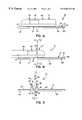
- FIG. 1 a of the drawingsis a side elevational view of the power source and the electrode assembly in a first orientation
- FIG. 1 b of the drawingsis a side elevational view of the power source and the electrode assembly in a second orientation
- FIG. 2 of the drawingsis a top plan view of the electrode assembly
- FIG. 3 of the drawingsis a bottom plan view of the power source
- FIG. 4 of the drawingsis a side elevational view of the electrode assembly
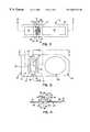
- FIG. 5 of the drawingsis partial cross-sectional view of the power source taken generally about lines 5 — 5 of FIG. 3;
- FIG. 6 of the drawingsis a partial cross-sectional view of the power source taken generally about lines 6 — 6 of FIG. 3;
- FIG. 7 of the drawingsis a top plan view of the electrode assembly
- FIG. 8 of the drawingsis a cross-sectional view of the electrode assembly taken about lines 8 — 8 of FIG. 2;
- FIG. 9 of the drawingsis a partial cross-sectional view of the apparatus taken generally about lines 10 — 10 of FIG. 1 b ;
- FIG. 10 of the drawingsis a top plan view of the apparatus positioned on the forearm of a user.
- Iontophoretic drug delivery apparatus 10is shown in FIG. 1 a as comprising electrode assembly 12 , power source 14 (which may comprise a dose controller with conventional electronic circuitry), means 16 (FIGS. 3 and 4) for facilitating mating engagement of the electrode assembly and the power source, means 18 for retaining such mating engagement, means 20 (FIG. 7) for electrically connecting the power source and the electrode assembly in at least two orientations, and, means 19 (FIG. 10) for biasing the electrical contacts of the power source with the electrical leads of the electrode assembly.
- the iontophoretic drug delivery systemutilizes a power source to drive a medicament or other beneficial agent to a patient through the patient's tissue (for example, through a patient's skin or ocular region).
- Electrode assembly 12is shown in detail in FIGS. 2, 7 and 8 as comprising base 21 , first interface 22 (FIG. 8 ), leads 24 , 25 (FIGS. 2 and 7 ), electrodes 27 , 29 and electrode pads 26 , 28 .
- Base 21includes upper surface 81 , lower surface 83 and central region 31 .
- the basecomprises a substantially liquid impervious planar material, such as, for example, mylar or the like.
- Pads 26 , 28are positioned on the lower surface of base 21 , and comprise a material which is capable of absorbing and controllably releasing a fluid (i.e. medicament or beneficial agent) through iontophoresis. While differently dimensioned pads are shown in FIG. 2, it will be understood that the particular dimensions are not limited and may be sized differently for different applications.
- Electrodes 27 , 29are positioned between pads 26 , 28 and base 21 , so as to be in abutting contact with the pads.
- Leads 24 and 25extend from the electrodes on the lower surface of base 21 to central region 31 of the upper surface of the base.
- the electrodes and the leadsmay comprise a variety of conventional materials, such as aluminum, silver, copper and the like.
- the leadscan be printed (through conventionally known techniques) onto the surface of the elastically deformable material/base of the electrode assembly.
- Mating engagement means 16includes first interface 22 and second interface 32 (FIG. 3 ).
- First interface 22is shown in FIGS. 4 and 8 as comprising outer surface 82 , inner region 84 and attachment means 85 .
- Inner region 84includes lower surface 91 (FIG. 8) and side surface 93 .
- the configuration of outer surface 82facilitates mating engagement of electrode assembly 12 and power source 14 .
- first interface 22is attached by way of attachment means 85 to central region 31 of base 21 so that leads 24 are proximate lower surface 91 of inner region 84 .
- attachment means 85comprises pegs 86 , 87 (FIG. 7) which are inserted through corresponding openings in base 21 and subsequently deformed (such as by swaging) to secure first interface 22 to base 21 .
- the pegsare preferably fabricated from a non-conductive material, such as plastic. Although, pegs have been disclosed, other types of attachment means are likewise contemplated, such as attachment through thermal welding or adhesives.
- Second interface 32is shown in FIGS. 1 a and 3 as being integrated with power source 14 .
- the power sourcecomprises power supply 60 , dose control means 62 , and electrical contacts 34 , 35 (FIG. 3 ).
- power supply 60includes a battery suitable of providing the necessary power to the apparatus.
- Various batteriesare suitable for use, including both primary and secondary batteries (i.e. NiMH, NiCd, Li-ion and alkaline, etc.).
- Dose control means 62may comprise conventional analog and/or digital circuitry which can monitor the application of power to electrical contacts 34 , 35 .
- Various dose control meanscan be utilized, and the invention is not limited to any particular dose control means.
- a portable battery operated power sourceis shown, the invention is equally applicable to AC/DC operated hand held units which are stand alone structures separate from the electrode assembly.
- Second interface 32is shown in detail in FIGS. 3, 5 and 6 as comprising inner surface 66 , projecting member 67 and sealing member 72 .
- inner surface 66is configured so as to cooperate with outer surface 82 of first interface 22 so as to direct the first and second interfaces into mating engagement therebetween.
- Projecting member 67is configured to matingly nest within inner region 84 of first interface 22 .
- Electrical contacts 34 , 35are disposed on projecting member 67 so as to electrically abut with leads 24 , 25 of electrode assembly 12 once the first and second interfaces are mated.
- the projecting memberalso facilitates alignment between the interfaces by operatively guiding the interfaces into mating engagement with each other.
- Seal member 72is shown in FIG. 6 as comprising an O-ring or other flexible elastomeric member positioned in the base of the slot defined by projecting member 67 and inner surface 66 .
- the seal membersubstantially precludes the passage of contamination and moisture into the interior of the power source during and after mating of the two interfaces. While the seal member is shown as being associated with the second interface, it is also contemplated that it be associated with lower surface 91 of first interface 22 . It is also contemplated that additional seals or other structures which protect the contacts and leads from moisture and contamination may also be utilized.
- first interfaceis shown as being associated with electrode assembly 12
- second interfaceis shown as being associated with power source 14
- first interfacemay be associated with power source 14
- second interfacemay be associated with electrode assembly 12 .
- First interface 22is shown in FIG. 4 as comprising outer surface 82 having a tapered configuration.
- the outer surfacetapers from the bottom up into a conical geometry.
- inner surface 66 (FIG. 5) of second interface 32has a geometry which enables slidable and matable cooperation within the first interface.
- the slope of surfaces 82 (FIG. 4) and 66 (FIG. 5)may be non-uniform. Specifically, decreasing the slope of these surfaces at regions 110 (FIG. 5) and 112 (FIG. 4 ), respectively, further facilitates the mating engagement between the first and second interfaces.
- Rotative positioning means 40is collectively shown in FIGS. 2 and 3 as comprising outer surface 82 of first interface 22 and inner surface 66 of second interface 32 each having elongated elliptical cross-sections.
- first and second interfaceswill be engageably rotated relative to each other until they are positioned into their fully engaged orientation.
- aligned attachment of the power source with the electrode assemblycan be achieved in either of two orientations, specifically, substantially 180 degrees apart. While the inner and outer surfaces of the first and second interfaces, respectively, have been shown and described as elongated and elliptical other geometries are also contemplated, provided they facilitate operative rotation in a manner similar to that as described.
- Retaining engagement means 18is shown in FIG. 3 and FIG. 4 as comprising biased tabs 48 (FIG. 3 and FIG. 6 ), and detents 46 (FIG. 4 ).
- detents 46are formed into outer surface 82 of first interface 22
- each of the biased tabs 48are associated with second interface 32 .
- each of the biased tabsinclude handle member 71 , pivot axis 73 , engagement region 75 and biasing spring 77 .
- engagement region 75 of tab 48lockably extends into detent 46 of first interface 32 , to, in turn, releasably lock the first and second interfaces together.
- biasing springpreferably comprises a coil spring, other conventional biasing elements are also contemplated for use.
- Electrical connecting means 20is shown in FIGS. 6 and 7 as comprising the spacial positioning of first and second leads 24 , 25 , respectively of electrode assembly 12 , and first and second contacts 34 , 35 , respectively, of power source 14 .
- Such spacial positioningenables electrical connection to be established in at least two orientations.
- first contact 34 and first lead 24are both positioned about the axis of rotation 101 (FIG. 6 and FIG. 8) of first interface 22 relative to the second interface 32 .
- second contact 35is spaced apart from first contact 34 a predetermined distance.
- first lead 25is positioned on either side of first lead 24 and spaced apart a distance corresponding to the distance separating first and second contacts 34 , 35 , respectively.
- first contact 34will always be electrically connected with first lead 24
- second contact 35will always be electrically connected to one of the two portions of second lead 25 .
- the electrode assembly and the power sourcemay be attachable in more than two orientations.
- the electrode assembly and the power sourcecan be capable of three mating orientations if first lead 24 (on the electrode assembly) and first contact 34 (on the power supply) are positioned about the axis of rotation 101 of the electrode assembly relative to the power source, and, provided that second lead 25 (on the electrode assembly) comprises three separate lead portions which are positioned radially and substantially equidistant from the first lead.
- one of the leadscan comprise a circular configuration, and another lead can be positioned in the center of the circle about the axis of rotation of the associated power source.
- the leadscomprise two concentric circles.
- the power sourcecan be operatively oriented into an infinite number of rotative positions.
- other geometries of the leads and interfaces, as well as the number of leads and contacts,are contemplated by the present invention.
- the biasing meanscomprises a combination of first and second contacts 34 , 35 , respectively, of the power source having a length which extends at least slightly below the bottom of lower surface 83 (FIG. 4) of the electrode assembly when operatively engaged together, and, wherein at least a portion of the electrode assembly (where the first and second leads 24 , 25 , respectively, are located) comprises a material 21 ′ which is capable of resistive deflection.
- the first and second contactswill push into the first and second leads to, in turn, cause the contacted portion of the leads and associated material 21 ′ to deflect outward. While some deflection occurs, material 21 ′ resists excessive deflection, and, in turn, actually maintains tight contact/continuity between the leads and corresponding contacts as a result of material 21 ′ being operatively secured to first interface 22 by attachment pegs 86 and 87 (FIG. 10 ). These attachment pegs (or other attachment means) cause material 21 ′ to counteract a significant portion of the deflection forces caused by the first and second contacts.
- Iontophoretic drug delivery device 10is operable by a user by first applying a medicament or a beneficial agent onto electrode pads 26 , 28 of electrode assembly 12 by conventionally known means. Once applied, electrode assembly 12 is positioned on a portion of the body proximate the region which is to receive treatment. The electrode assembly is secured to the user by conventional means, such as adhesive 130 applied adjacent to electrode pads 26 and 28 (FIG. 4 ). Additional adhesion can also result from the hydrated electrode pads as well. Once secure, the user is ready to attach power source 14 to electrode assembly 12 .
- power source 14is oriented so that outer surface 82 of first interface 22 (FIG. 4) substantially abuts inner surface 66 of second interface 32 (FIG. 3 ).
- the tapered configuration of outer surface 82 and the outwardly extending configuration of inner surface 66guide the first and second interfaces together.
- the elongated configuration of the inner and outer surfaceslikewise cooperate to rotate the first interface relative to the second interface until the interfaces are secured in a desired alignment with each other.
- the outer surface and the inner surfacecontinue to guide the structures into mating engagement.
- the electrical contacts of the power sourceabut electrical leads 24 , 25 of electrode assembly 12 and force the electrode material 21 ′ to deflect outward.
- the inherent elasticity of material 21 ′coupled with the securement of material 21 ′ to first interface 22 by attachment pegs 86 and 87 , maintains the material in a taught state throughout its deflection, to, in turn, maintain electrical leads 24 , 25 biased in electrical abutment against electrical contacts 34 , 35 .
- retaining means 18releasably secures the power source to the electrode assembly. Specifically, engagement regions 75 (FIG. 6) of tab 48 are biased into detents 46 (FIG. 4) positioned on outer surface 82 of electrode assembly 12 . As a result, the first and second interfaces are precluded from undesired inadvertent detachment, for example, during treatment.
- the apparatusadministers the medicament/beneficial agent through the,tissue of the user.
- the usermerely pivots/presses tabs 48 about axis 73 until engagement region 75 releases from detent 46 .
- the usercan withdraw the power source, and, in turn, first interface 22 from mating engagement with second interface 32 .
Landscapes
- Health & Medical Sciences (AREA)
- Engineering & Computer Science (AREA)
- Life Sciences & Earth Sciences (AREA)
- Biomedical Technology (AREA)
- Nuclear Medicine, Radiotherapy & Molecular Imaging (AREA)
- Radiology & Medical Imaging (AREA)
- Animal Behavior & Ethology (AREA)
- General Health & Medical Sciences (AREA)
- Public Health (AREA)
- Veterinary Medicine (AREA)
- Bioinformatics & Cheminformatics (AREA)
- Electrotherapy Devices (AREA)
- Measurement Of The Respiration, Hearing Ability, Form, And Blood Characteristics Of Living Organisms (AREA)
- Measuring Pulse, Heart Rate, Blood Pressure Or Blood Flow (AREA)
Abstract
Description
Claims (17)
Priority Applications (13)
| Application Number | Priority Date | Filing Date | Title |
|---|---|---|---|
| US09/458,239US6687536B1 (en) | 1999-12-09 | 1999-12-09 | Connection system for an iontophoretic drug delivery device |
| EP00108584AEP1106203B1 (en) | 1999-12-09 | 2000-04-20 | Connection system for an iontophoretic drug delivery device |
| DE60040827TDE60040827D1 (en) | 1999-12-09 | 2000-04-20 | Connection system for an iontophoresis device |
| AT00108584TATE414554T1 (en) | 1999-12-09 | 2000-04-20 | CONNECTION SYSTEM FOR AN IONTOPHORESIS DEVICE |
| EP08016261AEP2030648A1 (en) | 1999-12-09 | 2000-04-20 | Connection system for an iontophoretic drug delivery device |
| AU36444/00AAU3644400A (en) | 1999-12-09 | 2000-05-25 | Connection system for an iontophoretic drug delivery device |
| CA002313655ACA2313655A1 (en) | 1999-12-09 | 2000-07-10 | Connection system for an iontophoretic drug delivery device |
| JP2000213569AJP3523157B2 (en) | 1999-12-09 | 2000-07-14 | Connection system for iontophoretic drug delivery device |
| CA 2325195CA2325195A1 (en) | 1999-12-09 | 2000-11-07 | Connection system including a tether for an iontophoretic drug delivery device |
| AU71488/00AAU7148800A (en) | 1999-12-09 | 2000-11-08 | connection system including a tether for an iontophoretic drug delivery device |
| EP00126722AEP1106204A1 (en) | 1999-12-09 | 2000-12-05 | Connection system including a tether for an iontophoretic drug delivery device |
| JP2000375825AJP2001212248A (en) | 1999-12-09 | 2000-12-11 | Connection system including connection chain for chemical transmission device for iontophoresis |
| JP2003097917AJP3768969B2 (en) | 1999-12-09 | 2003-04-01 | Connection system for ion osmotic drug delivery device |
Applications Claiming Priority (1)
| Application Number | Priority Date | Filing Date | Title |
|---|---|---|---|
| US09/458,239US6687536B1 (en) | 1999-12-09 | 1999-12-09 | Connection system for an iontophoretic drug delivery device |
Publications (1)
| Publication Number | Publication Date |
|---|---|
| US6687536B1true US6687536B1 (en) | 2004-02-03 |
Family
ID=23819944
Family Applications (1)
| Application Number | Title | Priority Date | Filing Date |
|---|---|---|---|
| US09/458,239Expired - LifetimeUS6687536B1 (en) | 1999-12-09 | 1999-12-09 | Connection system for an iontophoretic drug delivery device |
Country Status (7)
| Country | Link |
|---|---|
| US (1) | US6687536B1 (en) |
| EP (2) | EP2030648A1 (en) |
| JP (2) | JP3523157B2 (en) |
| AT (1) | ATE414554T1 (en) |
| AU (1) | AU3644400A (en) |
| CA (1) | CA2313655A1 (en) |
| DE (1) | DE60040827D1 (en) |
Cited By (16)
| Publication number | Priority date | Publication date | Assignee | Title |
|---|---|---|---|---|
| US20050234516A1 (en)* | 2004-02-16 | 2005-10-20 | Gueret Jean-Louis H | Treatment kit, composite structure, electric exciter, and cosmetic treatment method |
| US20070230669A1 (en)* | 2002-01-18 | 2007-10-04 | Hazenfield Joey C | On-hold message system |
| US20080157713A1 (en)* | 2004-06-14 | 2008-07-03 | Massachusetts Institute Of Technology | Electrochemical methods, devices, and structures |
| US20090014320A1 (en)* | 2004-06-14 | 2009-01-15 | Massachusetts Institute Of Technology | Electrochemical actuator |
| US20090028824A1 (en)* | 2007-07-26 | 2009-01-29 | Entra Pharmaceuticals, Inc. | Systems and methods for delivering drugs |
| US20090182394A1 (en)* | 2008-01-07 | 2009-07-16 | Thomas Jerome Bachinski | Systems and methods for therapeutic electrical stimulation |
| US20090182393A1 (en)* | 2008-01-07 | 2009-07-16 | Thomas Jerome Bachinski | Systems and methods for therapeutic electrical stimulation |
| US7872396B2 (en) | 2004-06-14 | 2011-01-18 | Massachusetts Institute Of Technology | Electrochemical actuator |
| US7923895B2 (en) | 2004-06-14 | 2011-04-12 | Massachusetts Institute Of Technology | Electrochemical methods, devices, and structures |
| US8197276B2 (en)* | 2010-08-13 | 2012-06-12 | Djo, Llc | Low profile connector system |
| US8247946B2 (en) | 2004-06-14 | 2012-08-21 | Massachusetts Institute Of Technology | Electrochemical actuator |
| US8337457B2 (en) | 2010-05-05 | 2012-12-25 | Springleaf Therapeutics, Inc. | Systems and methods for delivering a therapeutic agent |
| US8368285B2 (en) | 2010-12-17 | 2013-02-05 | Massachusette Institute Of Technology | Electrochemical actuators |
| US10695562B2 (en) | 2009-02-26 | 2020-06-30 | The University Of North Carolina At Chapel Hill | Interventional drug delivery system and associated methods |
| US11534598B2 (en)* | 2020-10-08 | 2022-12-27 | Rootonix Co., Ltd. | Iontophoresis-based patch type skin care device |
| US20230092631A1 (en)* | 2020-10-08 | 2023-03-23 | ROOTONIX Co.,Ltd. | Iontophoresis-based patch type medicine absorption device |
Families Citing this family (3)
| Publication number | Priority date | Publication date | Assignee | Title |
|---|---|---|---|---|
| US8428708B1 (en) | 2012-05-21 | 2013-04-23 | Incline Therapeutics, Inc. | Self-test for analgesic product |
| US8301238B2 (en)* | 2011-03-31 | 2012-10-30 | Incline Therapeutics, Inc. | Two-part electrotransport device |
| US8428709B1 (en) | 2012-06-11 | 2013-04-23 | Incline Therapeutics, Inc. | Current control for electrotransport drug delivery |
Citations (4)
| Publication number | Priority date | Publication date | Assignee | Title |
|---|---|---|---|---|
| US5284471A (en)* | 1989-09-25 | 1994-02-08 | Becton, Dickinson And Company | Electrode and method used for iontophoresis |
| US5562607A (en)* | 1995-01-18 | 1996-10-08 | Alza Corporation | Electrotransport device having reusable controller power saver |
| US5603693A (en)* | 1993-09-10 | 1997-02-18 | Asulab S.A. | Three part device for the transdermic administration of drugs by electrophoresis or iontophoresis |
| US5846217A (en)* | 1997-07-29 | 1998-12-08 | Iomed, Inc. | Iontophoretic bioelectrode and method of using same |
Family Cites Families (4)
| Publication number | Priority date | Publication date | Assignee | Title |
|---|---|---|---|---|
| US4856188A (en)* | 1984-10-12 | 1989-08-15 | Drug Delivery Systems Inc. | Method for making disposable and/or replenishable transdermal drug applicators |
| US5458569A (en)* | 1993-06-08 | 1995-10-17 | Becton Dickinson And Company | Wearable iontophoresis system |
| AU7119096A (en)* | 1995-09-28 | 1997-04-17 | Becton Dickinson & Company | Iontophoretic drug delivery system, including reusable device |
| WO1999030773A1 (en)* | 1997-12-16 | 1999-06-24 | Alza Corporation | Regulator with artificial load to maintain regulated delivery |
- 1999
- 1999-12-09USUS09/458,239patent/US6687536B1/ennot_activeExpired - Lifetime
- 2000
- 2000-04-20ATAT00108584Tpatent/ATE414554T1/ennot_activeIP Right Cessation
- 2000-04-20EPEP08016261Apatent/EP2030648A1/ennot_activeWithdrawn
- 2000-04-20EPEP00108584Apatent/EP1106203B1/ennot_activeExpired - Lifetime
- 2000-04-20DEDE60040827Tpatent/DE60040827D1/ennot_activeExpired - Fee Related
- 2000-05-25AUAU36444/00Apatent/AU3644400A/ennot_activeAbandoned
- 2000-07-10CACA002313655Apatent/CA2313655A1/ennot_activeAbandoned
- 2000-07-14JPJP2000213569Apatent/JP3523157B2/ennot_activeExpired - Fee Related
- 2003
- 2003-04-01JPJP2003097917Apatent/JP3768969B2/ennot_activeExpired - Fee Related
Patent Citations (4)
| Publication number | Priority date | Publication date | Assignee | Title |
|---|---|---|---|---|
| US5284471A (en)* | 1989-09-25 | 1994-02-08 | Becton, Dickinson And Company | Electrode and method used for iontophoresis |
| US5603693A (en)* | 1993-09-10 | 1997-02-18 | Asulab S.A. | Three part device for the transdermic administration of drugs by electrophoresis or iontophoresis |
| US5562607A (en)* | 1995-01-18 | 1996-10-08 | Alza Corporation | Electrotransport device having reusable controller power saver |
| US5846217A (en)* | 1997-07-29 | 1998-12-08 | Iomed, Inc. | Iontophoretic bioelectrode and method of using same |
Cited By (44)
| Publication number | Priority date | Publication date | Assignee | Title |
|---|---|---|---|---|
| US20070230669A1 (en)* | 2002-01-18 | 2007-10-04 | Hazenfield Joey C | On-hold message system |
| US20050234516A1 (en)* | 2004-02-16 | 2005-10-20 | Gueret Jean-Louis H | Treatment kit, composite structure, electric exciter, and cosmetic treatment method |
| US7994686B2 (en) | 2004-06-14 | 2011-08-09 | Massachusetts Institute Of Technology | Electrochemical methods, devices, and structures |
| US7923895B2 (en) | 2004-06-14 | 2011-04-12 | Massachusetts Institute Of Technology | Electrochemical methods, devices, and structures |
| US8247946B2 (en) | 2004-06-14 | 2012-08-21 | Massachusetts Institute Of Technology | Electrochemical actuator |
| US8604664B2 (en) | 2004-06-14 | 2013-12-10 | Massachusetts Institute Of Technology | Electrochemical actuator |
| US20080157713A1 (en)* | 2004-06-14 | 2008-07-03 | Massachusetts Institute Of Technology | Electrochemical methods, devices, and structures |
| US8378552B2 (en) | 2004-06-14 | 2013-02-19 | Massachusetts Institute Of Technology | Electrochemical actuator |
| US7872396B2 (en) | 2004-06-14 | 2011-01-18 | Massachusetts Institute Of Technology | Electrochemical actuator |
| US20090014320A1 (en)* | 2004-06-14 | 2009-01-15 | Massachusetts Institute Of Technology | Electrochemical actuator |
| US8093781B2 (en) | 2004-06-14 | 2012-01-10 | Massachusetts Institute Of Technology | Electrochemical actuator |
| US20110098643A1 (en)* | 2004-06-14 | 2011-04-28 | Massachusetts Institute Of Technology | Electrochemical actuator |
| US8310130B2 (en) | 2004-06-14 | 2012-11-13 | Massachusetts Institute Of Technology | Electrochemical methods, devices, and structures |
| US7999435B2 (en) | 2004-06-14 | 2011-08-16 | Massachusetts Institute Of Technology | Electrochemical actuator |
| US20110098676A1 (en)* | 2007-07-26 | 2011-04-28 | Yet-Ming Chiang | Systems and methods for delivering drugs |
| US7828771B2 (en)* | 2007-07-26 | 2010-11-09 | Entra Pharmaceuticals, Inc. | Systems and methods for delivering drugs |
| US20090028824A1 (en)* | 2007-07-26 | 2009-01-29 | Entra Pharmaceuticals, Inc. | Systems and methods for delivering drugs |
| US8452409B2 (en) | 2008-01-07 | 2013-05-28 | Empi Inc. | Systems and methods for therapeutic electrical stimulation |
| US9242091B2 (en) | 2008-01-07 | 2016-01-26 | Empi Inc. | Systems and methods for therapeutic electrical stimulation |
| US11364379B2 (en) | 2008-01-07 | 2022-06-21 | Djo, Llc | Systems and methods for therapeutic electrical stimulation |
| US10967170B2 (en) | 2008-01-07 | 2021-04-06 | Djo, Llc | Systems and methods for therapeutic electrical stimulation |
| US8386032B2 (en) | 2008-01-07 | 2013-02-26 | Empi Inc. | Systems and methods for therapeutic electrical stimulation |
| US20090182393A1 (en)* | 2008-01-07 | 2009-07-16 | Thomas Jerome Bachinski | Systems and methods for therapeutic electrical stimulation |
| US20090182394A1 (en)* | 2008-01-07 | 2009-07-16 | Thomas Jerome Bachinski | Systems and methods for therapeutic electrical stimulation |
| US8768473B2 (en) | 2008-01-07 | 2014-07-01 | Empi Inc. | Systems and methods for therapeutic electrical stimulation |
| US8798739B2 (en) | 2008-01-07 | 2014-08-05 | Empi Inc. | Systems and methods for therapeutic electrical stimulation |
| US10610683B2 (en) | 2008-01-07 | 2020-04-07 | Djo, Llc | Systems and methods for therapeutic electrical stimulation |
| US8977366B2 (en) | 2008-01-07 | 2015-03-10 | Empi Inc. | Systems and methods for therapeutic electrical stimulation |
| US9044587B2 (en) | 2008-01-07 | 2015-06-02 | Empi Inc. | Systems and methods for therapeutic electrical stimulation |
| US9220896B2 (en) | 2008-01-07 | 2015-12-29 | Empi Inc. | Systems and methods for therapeutic electrical stimulation |
| US10071237B2 (en) | 2008-01-07 | 2018-09-11 | Djo, Llc | Systems and methods for therapeutic electrical stimulation |
| US9943683B2 (en) | 2008-01-07 | 2018-04-17 | Djo, Llc | Systems and methods for therapeutic electrical stimulation |
| US9643006B2 (en) | 2008-01-07 | 2017-05-09 | Djo, Llc | Systems and methods for therapeutic electrical stimulation |
| US9737705B2 (en) | 2008-01-07 | 2017-08-22 | Djo, Llc | Systems and methods for therapeutic electrical stimulation |
| US10695562B2 (en) | 2009-02-26 | 2020-06-30 | The University Of North Carolina At Chapel Hill | Interventional drug delivery system and associated methods |
| US8337457B2 (en) | 2010-05-05 | 2012-12-25 | Springleaf Therapeutics, Inc. | Systems and methods for delivering a therapeutic agent |
| US9768552B2 (en) | 2010-08-13 | 2017-09-19 | Djo, Llc | Low profile connector system |
| US9356393B2 (en) | 2010-08-13 | 2016-05-31 | Djo, Llc | Low profile connector system |
| US8821176B2 (en) | 2010-08-13 | 2014-09-02 | Djo, Llc | Low profile connector system |
| US8197276B2 (en)* | 2010-08-13 | 2012-06-12 | Djo, Llc | Low profile connector system |
| US8368285B2 (en) | 2010-12-17 | 2013-02-05 | Massachusette Institute Of Technology | Electrochemical actuators |
| US11534598B2 (en)* | 2020-10-08 | 2022-12-27 | Rootonix Co., Ltd. | Iontophoresis-based patch type skin care device |
| US20230092631A1 (en)* | 2020-10-08 | 2023-03-23 | ROOTONIX Co.,Ltd. | Iontophoresis-based patch type medicine absorption device |
| US12383733B2 (en)* | 2020-10-08 | 2025-08-12 | Rootonix Co., Ltd. | Iontophoresis-based patch type medicine absorption device |
Also Published As
| Publication number | Publication date |
|---|---|
| JP2003260144A (en) | 2003-09-16 |
| AU3644400A (en) | 2001-06-14 |
| JP2001170189A (en) | 2001-06-26 |
| JP3523157B2 (en) | 2004-04-26 |
| EP1106203A1 (en) | 2001-06-13 |
| EP1106203B1 (en) | 2008-11-19 |
| JP3768969B2 (en) | 2006-04-19 |
| ATE414554T1 (en) | 2008-12-15 |
| EP2030648A1 (en) | 2009-03-04 |
| DE60040827D1 (en) | 2009-01-02 |
| CA2313655A1 (en) | 2001-06-09 |
Similar Documents
| Publication | Publication Date | Title |
|---|---|---|
| US6687536B1 (en) | Connection system for an iontophoretic drug delivery device | |
| US5458569A (en) | Wearable iontophoresis system | |
| CA2145642C (en) | Electrotransport system having flexible means | |
| US5150708A (en) | Tabbed defibrillator electrode pad | |
| US4311152A (en) | Medical electrode and system for minimizing motion artifacts | |
| US8942830B2 (en) | Electrode delivery system | |
| US8727817B2 (en) | Screwless quick system for connecting a lead connector to a generator of an implantable medical device | |
| US20030040788A1 (en) | Skin-applied electrode pads | |
| JPH09500292A (en) | Electric drive agent delivery device | |
| US20080051692A1 (en) | Applicator cartridge for an electrokinetic delivery system for self administration of medicaments | |
| KR20080080492A (en) | Applicator cartridges in electrokinetic delivery systems for self-administration of drugs | |
| CA2624152A1 (en) | Combination cartridge and device for electrokinetic delivery of medicament to a treatment site | |
| US3762420A (en) | Defibrillation electrode | |
| EP1106204A1 (en) | Connection system including a tether for an iontophoretic drug delivery device | |
| US8321008B2 (en) | Combination cartridge and device for electrokinetic delivery of medicament to a treatment site | |
| US20060058841A1 (en) | Connector for a hemostatic compression pad | |
| CA2205010C (en) | Electrotransport device having reusable controller power saver | |
| MX2008006976A (en) | Combination cartridge and device for electrokinetic delivery of medicament to a treatment site |
Legal Events
| Date | Code | Title | Description |
|---|---|---|---|
| AS | Assignment | Owner name:IOMED, INC., UTAH Free format text:ASSIGNMENT OF ASSIGNORS INTEREST;ASSIGNORS:BECK, JON E.;LEAF, BRIAN KEITH;REEL/FRAME:010450/0114 Effective date:19991208 | |
| FEPP | Fee payment procedure | Free format text:PAYOR NUMBER ASSIGNED (ORIGINAL EVENT CODE: ASPN); ENTITY STATUS OF PATENT OWNER: LARGE ENTITY | |
| STCF | Information on status: patent grant | Free format text:PATENTED CASE | |
| REFU | Refund | Free format text:REFUND - PAYMENT OF MAINTENANCE FEE, 4TH YEAR, LARGE ENTITY (ORIGINAL EVENT CODE: R1551); ENTITY STATUS OF PATENT OWNER: LARGE ENTITY | |
| FEPP | Fee payment procedure | Free format text:PAT HOLDER CLAIMS SMALL ENTITY STATUS, ENTITY STATUS SET TO SMALL (ORIGINAL EVENT CODE: LTOS); ENTITY STATUS OF PATENT OWNER: LARGE ENTITY | |
| FPAY | Fee payment | Year of fee payment:4 | |
| AS | Assignment | Owner name:ENCORE MEDICAL ASSET CORORATION, NEVADA Free format text:ASSIGNMENT OF ASSIGNORS INTEREST;ASSIGNOR:IOMED, LLC (F/K/A IOMED, INC.);REEL/FRAME:019795/0561 Effective date:20070810 | |
| AS | Assignment | Owner name:BANK OF AMERICA, N.A., AS COLLATERAL AGENT, MASSAC Free format text:SECURITY AGREEMENT;ASSIGNORS:REABLE THERAPEUTICS HOLDINGS LLC;REABLE THERAPEUTICS FINANCE LLC;REEL/FRAME:020112/0579 Effective date:20070910 | |
| AS | Assignment | Owner name:CREDIT SUISSE, AS COLLATERAL AGENT, NEW YORK Free format text:SECURITY AGREEMENT;ASSIGNOR:ENCORE MEDICAL ASSET CORPORATION;REEL/FRAME:020234/0433 Effective date:20071120 | |
| FEPP | Fee payment procedure | Free format text:PAT HOLDER NO LONGER CLAIMS SMALL ENTITY STATUS, ENTITY STATUS SET TO UNDISCOUNTED (ORIGINAL EVENT CODE: STOL); ENTITY STATUS OF PATENT OWNER: LARGE ENTITY | |
| FPAY | Fee payment | Year of fee payment:8 | |
| AS | Assignment | Owner name:THE BANK OF NEW YORK MELLON, AS SECOND LIEN AGENT, Free format text:SECURITY AGREEMENT;ASSIGNORS:DJO, LLC;EMPI, INC.;ENCORE MEDICAL ASSET CORPORATION;AND OTHERS;REEL/FRAME:028078/0320 Effective date:20120320 | |
| FEPP | Fee payment procedure | Free format text:PAYER NUMBER DE-ASSIGNED (ORIGINAL EVENT CODE: RMPN); ENTITY STATUS OF PATENT OWNER: LARGE ENTITY Free format text:PAYOR NUMBER ASSIGNED (ORIGINAL EVENT CODE: ASPN); ENTITY STATUS OF PATENT OWNER: LARGE ENTITY | |
| AS | Assignment | Owner name:IOMED, LLC, UTAH Free format text:CHANGE OF NAME;ASSIGNOR:IOMED, INC.;REEL/FRAME:032536/0225 Effective date:20070810 | |
| AS | Assignment | Owner name:WELLS FARGO BANK, NATIONAL ASSOCIATION, AS THE COL Free format text:SECURITY INTEREST;ASSIGNORS:DJO, LLC;EMPI, INC.;ENCORE MEDICAL ASSET CORPORATION;AND OTHERS;REEL/FRAME:035614/0001 Effective date:20150507 | |
| AS | Assignment | Owner name:EMPI, INC., MINNESOTA Free format text:RELEASE BY SECURED PARTY;ASSIGNOR:THE BANK OF NEW YORK MELLON, AS SECOND LIEN AGENT;REEL/FRAME:035706/0457 Effective date:20150507 Owner name:ENCORE MEDICAL ASSET CORPORATION, CALIFORNIA Free format text:RELEASE BY SECURED PARTY;ASSIGNOR:CREDIT SUISSE AG, AS COLLATERAL AGENT;REEL/FRAME:035706/0497 Effective date:20150507 Owner name:DJO, LLC, CALIFORNIA Free format text:RELEASE BY SECURED PARTY;ASSIGNOR:THE BANK OF NEW YORK MELLON, AS SECOND LIEN AGENT;REEL/FRAME:035706/0457 Effective date:20150507 Owner name:RIKCO INTERNATIONAL, LLC, WISCONSIN Free format text:RELEASE BY SECURED PARTY;ASSIGNOR:CREDIT SUISSE AG, AS COLLATERAL AGENT;REEL/FRAME:035706/0497 Effective date:20150507 Owner name:DJO, LLC, CALIFORNIA Free format text:RELEASE BY SECURED PARTY;ASSIGNOR:CREDIT SUISSE AG, AS COLLATERAL AGENT;REEL/FRAME:035706/0497 Effective date:20150507 Owner name:RIKCO INTERNATIONAL, LLC, WISCONSIN Free format text:RELEASE BY SECURED PARTY;ASSIGNOR:THE BANK OF NEW YORK MELLON, AS SECOND LIEN AGENT;REEL/FRAME:035706/0457 Effective date:20150507 Owner name:ENCORE MEDICAL ASSET CORPORATION, CALIFORNIA Free format text:RELEASE BY SECURED PARTY;ASSIGNOR:THE BANK OF NEW YORK MELLON, AS SECOND LIEN AGENT;REEL/FRAME:035706/0457 Effective date:20150507 Owner name:MACQUARIE US TRADING LLC, AS COLLATERAL AGENT, ILL Free format text:SECURITY AGREEMENT;ASSIGNORS:DJO, LLC;EMPI, INC.;ENCORE MEDICAL ASSET CORPORATION;AND OTHERS;REEL/FRAME:035707/0398 Effective date:20150507 Owner name:THE BANK OF NEW YORK MELLON, AS SECOND LIEN AGENT, Free format text:SECURITY AGREEMENT;ASSIGNORS:DJO, LLC;EMPI, INC.;ENCORE MEDICAL ASSET CORPORATION;AND OTHERS;REEL/FRAME:035707/0454 Effective date:20150507 Owner name:THE BANK OF NEW YORK MELLON, AS THIRD LIEN AGENT, Free format text:SECURITY AGREEMENT;ASSIGNORS:DJO, LLC;EMPI, INC.;ENCORE MEDICAL ASSET CORPORATION;AND OTHERS;REEL/FRAME:035707/0498 Effective date:20150507 | |
| FPAY | Fee payment | Year of fee payment:12 | |
| AS | Assignment | Owner name:REABLE THERAPEUTICS HOLDINGS LLC, CALIFORNIA Free format text:RELEASE BY SECURED PARTY;ASSIGNOR:BANK OF AMERICA, N.A.;REEL/FRAME:048080/0952 Effective date:20071120 Owner name:REABLE THERAPEUTICS FINANCE LLC, CALIFORNIA Free format text:RELEASE BY SECURED PARTY;ASSIGNOR:BANK OF AMERICA, N.A.;REEL/FRAME:048080/0952 Effective date:20071120 | |
| AS | Assignment | Owner name:EMPI, INC., CALIFORNIA Free format text:RELEASE BY SECURED PARTY;ASSIGNOR:MACQUARIE US TRADING LLC AS COLLATERAL AGENT;REEL/FRAME:048655/0067 Effective date:20190222 Owner name:ENCORE MEDICAL, L.P., CALIFORNIA Free format text:RELEASE BY SECURED PARTY;ASSIGNOR:MACQUARIE US TRADING LLC AS COLLATERAL AGENT;REEL/FRAME:048655/0067 Effective date:20190222 Owner name:ENCORE MEDICAL ASSET CORPORATION, CALIFORNIA Free format text:RELEASE BY SECURED PARTY;ASSIGNOR:MACQUARIE US TRADING LLC AS COLLATERAL AGENT;REEL/FRAME:048655/0067 Effective date:20190222 Owner name:DJO, LLC, CALIFORNIA Free format text:RELEASE BY SECURED PARTY;ASSIGNOR:MACQUARIE US TRADING LLC AS COLLATERAL AGENT;REEL/FRAME:048655/0067 Effective date:20190222 Owner name:RIKCO INTERNATIONAL, LLC, CALIFORNIA Free format text:RELEASE BY SECURED PARTY;ASSIGNOR:MACQUARIE US TRADING LLC AS COLLATERAL AGENT;REEL/FRAME:048655/0067 Effective date:20190222 Owner name:ENCORE MEDICAL ASSET CORPORATION, CALIFORNIA Free format text:RELEASE BY SECURED PARTY;ASSIGNOR:THE BANK OF NEW YORK MELLON AS THIRD LIEN AGENT;REEL/FRAME:048608/0932 Effective date:20190222 Owner name:ENCORE MEDICAL, L.P., CALIFORNIA Free format text:RELEASE BY SECURED PARTY;ASSIGNOR:THE BANK OF NEW YORK MELLON AS THIRD LIEN AGENT;REEL/FRAME:048608/0932 Effective date:20190222 Owner name:DJO, LLC, CALIFORNIA Free format text:RELEASE BY SECURED PARTY;ASSIGNOR:THE BANK OF NEW YORK MELLON AS THIRD LIEN AGENT;REEL/FRAME:048608/0932 Effective date:20190222 Owner name:EMPI, INC., CALIFORNIA Free format text:RELEASE BY SECURED PARTY;ASSIGNOR:THE BANK OF NEW YORK MELLON AS THIRD LIEN AGENT;REEL/FRAME:048608/0932 Effective date:20190222 Owner name:RIKCO INTERNATIONAL, LLC, CALIFORNIA Free format text:RELEASE BY SECURED PARTY;ASSIGNOR:THE BANK OF NEW YORK MELLON AS THIRD LIEN AGENT;REEL/FRAME:048608/0932 Effective date:20190222 Owner name:ENCORE MEDICAL ASSET CORPORATION, CALIFORNIA Free format text:RELEASE BY SECURED PARTY;ASSIGNOR:THE BANK OF NEW YORK MELLON AS SECOND LIEN AGENT;REEL/FRAME:050129/0262 Effective date:20190222 Owner name:DJO, LLC, CALIFORNIA Free format text:RELEASE BY SECURED PARTY;ASSIGNOR:THE BANK OF NEW YORK MELLON AS SECOND LIEN AGENT;REEL/FRAME:050129/0262 Effective date:20190222 Owner name:ENCORE MEDICAL, L.P., CALIFORNIA Free format text:RELEASE BY SECURED PARTY;ASSIGNOR:THE BANK OF NEW YORK MELLON AS SECOND LIEN AGENT;REEL/FRAME:050129/0262 Effective date:20190222 Owner name:RIKCO INTERNATIONAL, LLC, CALIFORNIA Free format text:RELEASE BY SECURED PARTY;ASSIGNOR:THE BANK OF NEW YORK MELLON AS SECOND LIEN AGENT;REEL/FRAME:050129/0262 Effective date:20190222 Owner name:EMPI, INC., CALIFORNIA Free format text:RELEASE BY SECURED PARTY;ASSIGNOR:THE BANK OF NEW YORK MELLON AS SECOND LIEN AGENT;REEL/FRAME:050129/0262 Effective date:20190222 | |
| AS | Assignment | Owner name:ENCORE MEDICAL ASSET CORPORATION, CALIFORNIA Free format text:RELEASE BY SECURED PARTY;ASSIGNOR:WELLS FARGO BANK, NATIONAL ASSOCIATION AS COLLATERAL AGENT;REEL/FRAME:048672/0661 Effective date:20190222 Owner name:RIKCO INTERNATIONAL, LLC, CALIFORNIA Free format text:RELEASE BY SECURED PARTY;ASSIGNOR:WELLS FARGO BANK, NATIONAL ASSOCIATION AS COLLATERAL AGENT;REEL/FRAME:048672/0661 Effective date:20190222 Owner name:DJO, LLC, CALIFORNIA Free format text:RELEASE BY SECURED PARTY;ASSIGNOR:WELLS FARGO BANK, NATIONAL ASSOCIATION AS COLLATERAL AGENT;REEL/FRAME:048672/0661 Effective date:20190222 Owner name:ENCORE MEDICAL, L.P., CALIFORNIA Free format text:RELEASE BY SECURED PARTY;ASSIGNOR:WELLS FARGO BANK, NATIONAL ASSOCIATION AS COLLATERAL AGENT;REEL/FRAME:048672/0661 Effective date:20190222 Owner name:EMPI, INC., CALIFORNIA Free format text:RELEASE BY SECURED PARTY;ASSIGNOR:WELLS FARGO BANK, NATIONAL ASSOCIATION AS COLLATERAL AGENT;REEL/FRAME:048672/0661 Effective date:20190222 |