US6687445B2 - Double-clad optical fiber for lasers and amplifiers - Google Patents
Double-clad optical fiber for lasers and amplifiersDownload PDFInfo
- Publication number
- US6687445B2 US6687445B2US09/888,916US88891601AUS6687445B2US 6687445 B2US6687445 B2US 6687445B2US 88891601 AUS88891601 AUS 88891601AUS 6687445 B2US6687445 B2US 6687445B2
- Authority
- US
- United States
- Prior art keywords
- optical fiber
- core
- inner cladding
- cladding
- double
- Prior art date
- Legal status (The legal status is an assumption and is not a legal conclusion. Google has not performed a legal analysis and makes no representation as to the accuracy of the status listed.)
- Expired - Lifetime, expires
Links
Images


Classifications
- G—PHYSICS
- G02—OPTICS
- G02B—OPTICAL ELEMENTS, SYSTEMS OR APPARATUS
- G02B6/00—Light guides; Structural details of arrangements comprising light guides and other optical elements, e.g. couplings
- G02B6/02—Optical fibres with cladding with or without a coating
- G02B6/036—Optical fibres with cladding with or without a coating core or cladding comprising multiple layers
- G02B6/03616—Optical fibres characterised both by the number of different refractive index layers around the central core segment, i.e. around the innermost high index core layer, and their relative refractive index difference
- G02B6/03622—Optical fibres characterised both by the number of different refractive index layers around the central core segment, i.e. around the innermost high index core layer, and their relative refractive index difference having 2 layers only
- C—CHEMISTRY; METALLURGY
- C03—GLASS; MINERAL OR SLAG WOOL
- C03B—MANUFACTURE, SHAPING, OR SUPPLEMENTARY PROCESSES
- C03B37/00—Manufacture or treatment of flakes, fibres, or filaments from softened glass, minerals, or slags
- C03B37/01—Manufacture of glass fibres or filaments
- C03B37/012—Manufacture of preforms for drawing fibres or filaments
- C03B37/0128—Manufacture of preforms for drawing fibres or filaments starting from pulverulent glass
- C03B37/01291—Manufacture of preforms for drawing fibres or filaments starting from pulverulent glass by progressive melting, e.g. melting glass powder during delivery to and adhering the so-formed melt to a target or preform, e.g. the Plasma Oxidation Deposition [POD] process
- C03B37/01294—Manufacture of preforms for drawing fibres or filaments starting from pulverulent glass by progressive melting, e.g. melting glass powder during delivery to and adhering the so-formed melt to a target or preform, e.g. the Plasma Oxidation Deposition [POD] process by delivering pulverulent glass to the deposition target or preform where the powder is progressively melted, e.g. accretion
- C—CHEMISTRY; METALLURGY
- C03—GLASS; MINERAL OR SLAG WOOL
- C03B—MANUFACTURE, SHAPING, OR SUPPLEMENTARY PROCESSES
- C03B37/00—Manufacture or treatment of flakes, fibres, or filaments from softened glass, minerals, or slags
- C03B37/01—Manufacture of glass fibres or filaments
- C03B37/012—Manufacture of preforms for drawing fibres or filaments
- C03B37/014—Manufacture of preforms for drawing fibres or filaments made entirely or partially by chemical means, e.g. vapour phase deposition of bulk porous glass either by outside vapour deposition [OVD], or by outside vapour phase oxidation [OVPO] or by vapour axial deposition [VAD]
- C—CHEMISTRY; METALLURGY
- C03—GLASS; MINERAL OR SLAG WOOL
- C03C—CHEMICAL COMPOSITION OF GLASSES, GLAZES OR VITREOUS ENAMELS; SURFACE TREATMENT OF GLASS; SURFACE TREATMENT OF FIBRES OR FILAMENTS MADE FROM GLASS, MINERALS OR SLAGS; JOINING GLASS TO GLASS OR OTHER MATERIALS
- C03C25/00—Surface treatment of fibres or filaments made from glass, minerals or slags
- C03C25/10—Coating
- C03C25/104—Coating to obtain optical fibres
- C03C25/105—Organic claddings
- C—CHEMISTRY; METALLURGY
- C03—GLASS; MINERAL OR SLAG WOOL
- C03C—CHEMICAL COMPOSITION OF GLASSES, GLAZES OR VITREOUS ENAMELS; SURFACE TREATMENT OF GLASS; SURFACE TREATMENT OF FIBRES OR FILAMENTS MADE FROM GLASS, MINERALS OR SLAGS; JOINING GLASS TO GLASS OR OTHER MATERIALS
- C03C25/00—Surface treatment of fibres or filaments made from glass, minerals or slags
- C03C25/10—Coating
- C03C25/465—Coatings containing composite materials
- C03C25/47—Coatings containing composite materials containing particles, fibres or flakes, e.g. in a continuous phase
- G—PHYSICS
- G02—OPTICS
- G02B—OPTICAL ELEMENTS, SYSTEMS OR APPARATUS
- G02B6/00—Light guides; Structural details of arrangements comprising light guides and other optical elements, e.g. couplings
- G02B6/02—Optical fibres with cladding with or without a coating
- G02B6/02295—Microstructured optical fibre
- C—CHEMISTRY; METALLURGY
- C03—GLASS; MINERAL OR SLAG WOOL
- C03B—MANUFACTURE, SHAPING, OR SUPPLEMENTARY PROCESSES
- C03B2201/00—Type of glass produced
- C03B2201/06—Doped silica-based glasses
- C03B2201/20—Doped silica-based glasses doped with non-metals other than boron or fluorine
- C03B2201/28—Doped silica-based glasses doped with non-metals other than boron or fluorine doped with phosphorus
- C—CHEMISTRY; METALLURGY
- C03—GLASS; MINERAL OR SLAG WOOL
- C03B—MANUFACTURE, SHAPING, OR SUPPLEMENTARY PROCESSES
- C03B2201/00—Type of glass produced
- C03B2201/06—Doped silica-based glasses
- C03B2201/30—Doped silica-based glasses doped with metals, e.g. Ga, Sn, Sb, Pb or Bi
- C03B2201/34—Doped silica-based glasses doped with metals, e.g. Ga, Sn, Sb, Pb or Bi doped with rare earth metals, i.e. with Sc, Y or lanthanides, e.g. for laser-amplifiers
- C—CHEMISTRY; METALLURGY
- C03—GLASS; MINERAL OR SLAG WOOL
- C03B—MANUFACTURE, SHAPING, OR SUPPLEMENTARY PROCESSES
- C03B2203/00—Fibre product details, e.g. structure, shape
- C03B2203/10—Internal structure or shape details
- C03B2203/22—Radial profile of refractive index, composition or softening point
- C03B2203/23—Double or multiple optical cladding profiles
- G—PHYSICS
- G02—OPTICS
- G02B—OPTICAL ELEMENTS, SYSTEMS OR APPARATUS
- G02B6/00—Light guides; Structural details of arrangements comprising light guides and other optical elements, e.g. couplings
- G02B6/02—Optical fibres with cladding with or without a coating
- G02B6/02295—Microstructured optical fibre
- G02B6/02314—Plurality of longitudinal structures extending along optical fibre axis, e.g. holes
- G02B6/02342—Plurality of longitudinal structures extending along optical fibre axis, e.g. holes characterised by cladding features, i.e. light confining region
- G02B6/02376—Longitudinal variation along fibre axis direction, e.g. tapered holes
- G—PHYSICS
- G02—OPTICS
- G02B—OPTICAL ELEMENTS, SYSTEMS OR APPARATUS
- G02B6/00—Light guides; Structural details of arrangements comprising light guides and other optical elements, e.g. couplings
- G02B6/02—Optical fibres with cladding with or without a coating
- G02B6/036—Optical fibres with cladding with or without a coating core or cladding comprising multiple layers
- G02B6/03694—Multiple layers differing in properties other than the refractive index, e.g. attenuation, diffusion, stress properties
- H—ELECTRICITY
- H01—ELECTRIC ELEMENTS
- H01S—DEVICES USING THE PROCESS OF LIGHT AMPLIFICATION BY STIMULATED EMISSION OF RADIATION [LASER] TO AMPLIFY OR GENERATE LIGHT; DEVICES USING STIMULATED EMISSION OF ELECTROMAGNETIC RADIATION IN WAVE RANGES OTHER THAN OPTICAL
- H01S3/00—Lasers, i.e. devices using stimulated emission of electromagnetic radiation in the infrared, visible or ultraviolet wave range
- H01S3/05—Construction or shape of optical resonators; Accommodation of active medium therein; Shape of active medium
- H01S3/06—Construction or shape of active medium
- H01S3/063—Waveguide lasers, i.e. whereby the dimensions of the waveguide are of the order of the light wavelength
- H01S3/067—Fibre lasers
- H01S3/06708—Constructional details of the fibre, e.g. compositions, cross-section, shape or tapering
- H01S3/06729—Peculiar transverse fibre profile
- H—ELECTRICITY
- H01—ELECTRIC ELEMENTS
- H01S—DEVICES USING THE PROCESS OF LIGHT AMPLIFICATION BY STIMULATED EMISSION OF RADIATION [LASER] TO AMPLIFY OR GENERATE LIGHT; DEVICES USING STIMULATED EMISSION OF ELECTROMAGNETIC RADIATION IN WAVE RANGES OTHER THAN OPTICAL
- H01S3/00—Lasers, i.e. devices using stimulated emission of electromagnetic radiation in the infrared, visible or ultraviolet wave range
- H01S3/09—Processes or apparatus for excitation, e.g. pumping
- H01S3/091—Processes or apparatus for excitation, e.g. pumping using optical pumping
- H01S3/094—Processes or apparatus for excitation, e.g. pumping using optical pumping by coherent light
- H01S3/094003—Processes or apparatus for excitation, e.g. pumping using optical pumping by coherent light the pumped medium being a fibre
- H01S3/094007—Cladding pumping, i.e. pump light propagating in a clad surrounding the active core
Definitions
- This inventionrelates to optical fibers and, more particularly, to an optical fiber having an inner cladding for receiving pump radiation that is to be absorbed by active material in the core of the optical fiber.
- Optical fiber lasers and amplifiersare known in the art.
- rare earth materials disposed in the core of the optical fiber laser or amplifierabsorb pump radiation of a predetermined wavelength and, responsive thereto, provide or amplify light of a different wavelength for propagation in the core.
- the well-known erbium doped fiber amplifierreceives pump radiation having a wavelength of 980 or 1480 nanometers (nm) and amplifies an optical signal having a wavelength in the 1550 nm region and that propagates in the core.
- the pump radiationcan be introduced directly to the core, which can be difficult due to the small size of the core, or can be introduced to the cladding layer surrounding the core and absorbed by the core as the rays propagating in the cladding layer intersect the core.
- Lasers and amplifiers with the pump radiation introduced to the cladding layerare known as “double-clad” or “cladding-pumped” optical devices, and facilitate the scale-up of lasers and amplifiers to higher power systems.
- FIG. 1illustrates an optical fiber having a core 20 , an inner, or pump, multimode cladding layer 22 , and an outer cladding layer 24 .
- the inner cladding layer 22confines light rays 26 , which represent the light generated or amplified in the core 20 , to the core 20 .
- the outer cladding 24confines light rays 28 , which represent pump radiation propagating in the inner cladding 22 , to the inner cladding 22 .
- the rays 28periodically intersect the core 20 for absorption by the active material therein so as to generate or amplify the light propagating in the core 20 , represented by the rays 26 . Because the inner cladding 22 is multimode, many rays other than those shown by reference numeral 28 can propagate in the inner cladding 22 .
- Absorption per unit lengthis a useful figure of merit for evaluating a double-clad optical fiber laser or amplifier. It is typically desirable that the amplifier or laser has a high absorption per unit length, indicating that the pump radiation frequently intersects the core. It has been determined by various researchers over the years that a standard circular fiber geometry, such as is desirable when fabricating an optical fiber for transmission over substantial distances, does not optimally promote intersection of the core by the radiation pumped into the cladding. Unfortunately, some rays of the pump radiation, known in the art as “skew” rays, can essentially propagate down the optical fiber while spiraling around the core without substantially intersecting the core, as shown in FIG. 1B, where pump radiation rays 28 A do not intersect the core 20 . The existence of skew rays leads to a low absorption per unit length of the optical fiber device, and hence detracts from the performance of the optical fiber laser or amplifier.
- the prior artteaches two approaches for enhancing the intersection of the pump radiation with the core and hence raising the absorption per unit length of the optical fiber amplifier or laser.
- the coreis relocated to intersect more of the rays of the pump radiation.
- the corecan be offset from the center of the optical fiber so as to enhance the intersection of pump light with the core.
- the shape of the outer circumference of the inner, or pump, cladding layeris modified to “mode mix” or scatter more rays towards the core so as to intersect with the core.
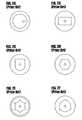
- the inner claddingcan have a rectangular outer circumference. See also FIG. 2C, where the inner cladding has a “D”-shaped outer circumference that includes a flat section, as disclosed in U.S. Pat. No. 5,864,645, issued Jan. 26, 1999 to Zellmer et al.
- the outer circumference of the claddingis shaped as a polygon, such as a hexagon, as disclosed in U.S. Pat. No.
- the outer circumference of the inner claddinghas a “star” shape, as disclosed in U.S. Pat. No. 5,949,941, issued Sep. 7, 1999 to DiGiovanni and illustrated in FIG. 2 E. See also WO 99/30391, published Jun. 17, 1999, disclosing an optical fiber having a core, inner and outer claddings, and a series of circularly shaped perturbations or irregularities formed in the otherwise circular outer boundary of the inner cladding, as shown in FIG. 2 F.
- the optical fiberis drawn from a preform having rods inserted into holes drilled into the preform.
- the fiberscan be difficult to splice to a fiber having a standard, circular geometry in a manner that provides for an acceptably low loss of light, as is often required in a practical application.
- the offset core fiber of FIG. 2Acan be particularly difficult to splice.
- designs shown in FIGS. 2B-2F, wherein the outer circumference of the inner cladding is shapedcan require shaping of the preform from which the fiber is drawn. Shapes that include flat areas, such as the polygon design discussed above, can be difficult and/or time consuming, and hence more expensive, to fabricate. The flat areas are typically first machined into the preform from which the optical fiber is drawn.
- shaped areas of the preform to deform and change shape when the fiber is drawn at the most desirable temperaturesAccordingly, often the draw temperature is reduced to preserve the desired shape of the outer circumference of the cladding.
- a reduced draw temperaturetypically produces optical fibers having higher attenuation and lower mechanical strength.
- the present inventionprovides a double-clad optical fiber that includes the following: a core having a first index of refraction and including an active material; a multimode inner cladding layer for receiving pump radiation, the inner cladding layer disposed about the core and including material having a second index of refraction that is less than the first index of refraction; a second cladding layer disposed about the inner cladding layer, the second cladding layer having a third index of refraction that is less than the second index of refraction.
- the multimode inner cladding of the double-clad fiberincludes truncated regions having an index of refraction that is different than the material of the inner cladding that surrounds the truncated regions. Accordingly, the truncated regions promote the scattering of pump radiation propagating in the multimode inner cladding for increasing the absorption by the core of pump radiation.
- the truncated regionscan include filaments extending along the length of the double-clad fiber.
- the optical fibercan be drawn from a preform wherein the inner cladding is formed at least in part via outside vapor deposition, and wherein particles of the first material are distributed with material of the inner cladding deposited via outside vapor deposition.
- the double-clad optical fibercan be drawn from a preform formed at least in part from a frit, and wherein the first material includes material introduced at least in part by exposure of the frit to a selected solution.
- the truncated regionscan also include voids defined by material of the inner cladding, and which may be filled with a gas.
- the truncated regionsare concentrated nearer to the outer circumference of the inner cladding than to the core of the optical fiber.
- the truncated regionscan be distributed in a band spaced from the core of the fiber by a region of the inner cladding having substantially no truncated regions.
- the distribution of truncated regionscan include truncated regions having a maximum diameter of less than 100 microns.
- the active materialcan includes at least one of erbium, ytterbium, neodymium and thulium and other rare earth materials.
- the double-clad optical fibercan include at least one bend. Bending the fiber is considered to promote mode mixing of the light in the inner cladding and hence a higher absorption of the pump radiation by the active material per unit length of the double-clad optical fiber.
- the inventionalso includes methods practiced in accordance with the teachings herein.
- a method of forming a cladding for being disposed about the core of an elongate optical articlecan include the following steps: providing a elongate glass article; adding glass to the article for forming a first part of the cladding so as to disposed about the core when present, the added glass including discrete regions having a different index of refraction than the added glass; and adding glass without discrete regions to the elongate glass article for forming another part of the same cladding so as to be disposed about the core when present.
- a method of forming a cladding for being disposed about the core of an optical articlecan include the following steps: providing an elongate glass article; adhering a layer of soot to the elongate glass article for forming a portion of the cladding so as to be disposed about the core when present; sintering the layer of soot so as to form a first sintered layer including bubbles; adhering a different layer of soot to the elongate glass article for forming a different portion of the cladding so to be disposed about the core when present; sintering the different layer of soot so as to form a different sintered layer substantially free from bubbles; and disposing a second cladding about the cladding, where the second cladding has an index of refraction lower than that of the cladding.
- a method of forming a cladding for being disposed about the core of an optical articlecan include the following steps: providing a hollow elongate glass article; adhering a layer of soot to the elongate glass article for forming a portion of the cladding so as to be disposed about the core when present; sintering the layer of soot so as to form a sintered layer including bubbles; providing a second elongate glass article for providing one of at least a portion of the core and a different portion of the cladding where the different portion is substantially free of bubbles; and oversleeving one the glass articles with the other of the glass articles.
- a method of forming a cladding for surrounding the core of an optical articlecan include the following steps: providing a elongate glass article; adhering a layer of soot to the elongate glass article for forming a portion of the cladding so as to be disposed about the core when present; sintering said layer of soot so as to form a first sintered layer of the cladding; adhering a different layer of soot to the elongate glass article for forming a different portion of said cladding so as to be disposed about the core when present; exposing only the different layer of soot to a selected material in the form of a gas or liquid for absorption by the different layer of soot; and sintering the different layer of soot so as to form a second sintered layer of said cladding.
- a method of forming a cladding for being disposed about the core of an optical articlecan include the following steps: providing a elongate glass article; adhering a layer of soot to the elongate glass article for forming a portion of the cladding so as to be disposed about the core when present; distributing particles having an index of refraction different than the index of refraction of the soot with the layer of soot; and sintering the soot layer.
- a method of forming a cladding for being disposed about the core of an optical articlecan include the following steps: providing a hollow elongate glass article; adhering a layer of soot to the inside of the elongate glass article for forming a portion of the cladding so as to be disposed about the core when present; exposing the layer of soot to a selected material in one of a gas and liquid form for absorption by the soot; sintering the soot; providing a second glass article for providing one of at least a portion of the core and a different portion of the cladding; and oversleeving one of the glass articles with the other of the glass articles.
- the inventioncan provide a double-clad optical fiber that promotes absorption by active material in the core of pump radiation and that can retain, if desired, a circularly shaped inner cladding for improved splicing to standard optical fibers.
- FIG. 1Ais a perspective view of a double-clad optical fiber and illustrates the intersection of pump radiation propagating in the inner cladding layer of the fiber with the core of the fiber;
- FIG. 1Bis a cross section taken along section line 1 B— 1 B of FIG. 1 A and illustrates skew rays of pump radiation propagating in the inner cladding of the optical fiber and spiraling without intersecting the core of the fiber;
- FIG. 2Ais a cross section of a prior art optical fiber having an offset core
- FIG. 2Bis a cross section of a prior art optical fiber having a rectangular shaped inner cladding
- FIG. 2Cis a cross section of a prior art optical fiber having a “D” shaped inner cladding
- FIG. 2Dis a cross section of a prior art optical fiber having a hexagonal shaped inner cladding
- FIG. 2Eis a cross section of a prior art optical fiber having a “star” shaped inner cladding
- FIG. 2Fis a cross section of a prior art optical fiber having an inner cladding including circularly shaped irregularities
- FIG. 3is a perspective view of one embodiment of an optical fiber according to the present invention.
- FIG. 4is a cross section of the optical fiber shown in FIG. 3, taken along section line 4 — 4 of FIG. 3;
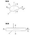
- FIG. 5Aillustrates one example of a truncated region that can be included in the inner cladding of an optical fiber of the present invention
- FIG. 5Billustrates another example of a truncated region that can be included in the inner cladding of an optical fiber of the present invention
- FIG. 6illustrates one technique for distributing particles in a preform for forming truncated regions in an optical fiber drawn from the preform
- FIG. 7Aillustrates exposing soot to a selected solution
- FIG. 7Billustrates depositing soot on the inside of a glass tube.
- FIG. 3is a perspective view of one embodiment of a double-clad optical fiber according to the present invention.
- the optical fiber 30includes a core 32 , a multimode cladding layer 34 disposed about the core 32 , and a second cladding layer 36 disposed about the multimode cladding layer 34 .
- the term “disposed about”, as used herein,refers to one layer surrounding, at least partially, another layer, and does not require that the layers be adjacent.
- the multimode cladding layer 34has a lower index of refraction than the core 32 , such that the laser light to be amplified or generated in the core 32 is confined largely to the core 32 by the phenomenon of total internal reflection.
- the second cladding layer 36includes material having a lower index of refraction than the multimode cladding layer 34 such that the pump radiation is confined largely to the multimode cladding layer 34 .
- the double-clad optical fiber 30can also include an additional layer or layers, such as, for example, a protective layer or layers disposed about said second cladding layer 36 .
- the additional layer(s)can include a polymer (e.g., acrylate) protective layer disposed about the second cladding layer 36 .
- the second cladding layer 36can be a glass or a polymer, or other material having a suitable index or refraction (i.e., lower than an index of refraction of the multimode cladding layer 34 ) and appropriate mechanical properties. If the second cladding layer 36 includes a polymer, use of a protective layer disposed about the second cladding layer 36 may be superfluous.
- Reference numeral 38 in FIG. 4, which is a cross section of the optical fiber 30 shown in FIG. 3 taken along section line 4 — 4schematically illustrates one possible placement of the additional layer or layers.
- the core 32typically includes active material, such as one or more rare-earth dopants, which can be selected from the Lanthanide group of elements in the periodic table, in a glass matrix, which can be a silica glass matrix.
- active materialsuch as one or more rare-earth dopants, which can be selected from the Lanthanide group of elements in the periodic table
- a glass matrixwhich can be a silica glass matrix.
- Other materialssuch as Ge, P, Al, B, F, etc. can also be included in the core 32 or in one or more of the other layers, such as cladding layers 34 and 36 .
- such materialsare typically added dopants for any one or more of variety of reasons, such as, for example, to modify the refractive index of the core 32 or of one or more of the cladding layers, to improve the performance of the rare earth dopants in the core 32 , to render the core 32 or one or more of the cladding layers sufficiently photosensitive, or to improve the radiation hardness of the core 32 or one or more of the cladding layers.
- the pump radiationintersects the core 32 , the pump radiation is absorbed by the rare earth material, such as erbium, in the core 32 for amplifying or generating the laser light propagating in the core 32 .
- the multimode inner claddingincludes truncated regions 40 distributed in the inner cladding 34 .
- the truncated regions 40include an index of refraction that is different than at least the material of the inner cladding 34 that surrounds the truncated regions 40 .
- the distribution of truncated regionspromotes the scattering of pump radiation propagating in the inner cladding 34 for increasing the absorption by the core 32 of the pump radiation. The efficiency of the double-clad optical fiber 30 is thereby enhanced.
- truncated regionsis selected in part to distinguish references herein to the regions 40 formed in the inner cladding 34 of the optical fiber 30 and shown in FIG. 3 from particles 40 A and discrete regions that can be included in a preform, as discussed below, and which will contribute to the truncated regions 40 when the preform is drawn to provide an optical fiber.
- discrete and truncateddo indicate that discrete regions and truncated regions 40 are of limited extent in all directions, including the longitudinal direction 44 and do not extend for the full length of the core 32 of a preform or fiber.
- a preform, as a fibercan have a core and a cladding, and the core and the cladding substantially retain their relative diameters upon drawing of a fiber from the preform.
- the truncated regions 40can have substantially the same coefficient of thermal expansion as at least the material of the inner cladding 34 that surrounds the truncated regions 40 , such that the truncated regions 40 do not induce stress in the inner cladding 34 .
- the truncated regions 40are preferably concentrated nearer to the outer circumference 50 of the inner cladding 34 than to the core 32 of the optical fiber 30 .
- the truncated regions 40can be concentrated in a band 54 having an inner circumference 56 and an outer circumference 58 .
- the outer circumference 58 of the band 54can be adjacent the outer circumference 50 of the inner cladding 34 , and in one embodiment of the invention the truncated regions 40 are distributed up to the outer circumference 50 of the inner cladding 34 , such that the outer circumference 50 of the inner cladding 34 and the outer circumference 58 of the band 54 are substantially coextensive.
- the truncated regions 40are uniformly distributed within the band 54 .
- the truncated regionsare concentrated in the band 54 spaced from the core 32 by a region of the inner cladding 34 having a substantially no truncated regions 40 .
- the truncated regions 40can also be distributed in band that is spaced from the core 32 and the outside circumference 50 of the inner cladding 34 by regions of the inner cladding 34 having substantially no truncated regions 40 .
- FIG. 5Aillustrates a typical truncated region 40 .
- the truncated regions 40need not be spherical, and can be irregularly shaped, having a maximum diameter 60 and a minimum diameter 64 . Because, as indicated below, the truncated regions 40 will typically be shaped during the drawing of a preform that includes particles or discrete regions, the truncated regions 40 typically have a maximum diameter 60 along the longitudinal axis 44 of the optical fiber 30 .
- the optical fiber 30is typically drawn from a preform.
- a preformcan be can be made using methods such as vapor phase axial deposition (VAD), outside vapor deposition (OVD), modified chemical vapor deposition (MCVD), or inside vapor deposition (IVD), as well as other methods known to those of ordinary skill in the art.
- IVDrefers to the process wherein soot formed by flame hydrolysis flows through the inside of a tube.
- FIG. 6illustrates one technique for distributing particles in a preform for forming truncated regions in an optical fiber drawn from the preform.
- the preform 100can include, or be formed about and then removed from, a center portion 104 , which can be an elongate glass article such as a rod or tube.
- the center portion 104can be a tube that has had layers and/or dopants added to the tube via another type of deposition processes, such as solution doping or MCVD.
- Tube and rods having selected glass compositions and suitable for use in preformsare available from vendors such as Heraeus Amersil of Duluth, Ga., USA.
- the torch 108receives a precursor gas 110 and a fuel 112 for producing the flame 114 and accompanying soot 116 that then adheres to the preform center portion 104 .
- the torch 108translates back and forth, as indicated by reference numeral 120 , as the preform 100 rotates, as indicated by reference numeral 122 , for promoting uniform deposition of the soot 116 (also known as a frit), which is typically adhered to the center portion 104 in layers.
- Control of the type and amount of the precursor gas 110can allow variation of the type and amount of soot deposited on the center portion 104 .
- sootcan be deposited so as to form an inner soot region 116 A and an outer soot region 116 B.
- the inner soot region 116 Aforms, after sintering and drawing of the preform, the inner cladding 34 of the fiber 30 , and the outer soot region 116 B similarly forms the second cladding layer 36 .
- the reservoir 130includes particles 40 A, which can be particles of glass having a selected index of refraction and size, and which can be distributed in the frit 116 via the nozzle 132 .
- the nozzle 132can also be fed an inert gas 136 for aiding in dispensation of the particles 40 A from the nozzle 132 , and is typically translated back and forth, as indicated by reference numeral 140 .
- Proper control of the dispensation of the particles 40 A and soot 116can provide the desired distribution of the particles at the desired radius or radii.
- the particlescan be distributed so as to be concentrated in an outer region 116 B, which can correspond, upon drawing of the fiber 30 , to the band 54 of truncated regions 40 shown in FIG. 4 .
- At least part of the inner soot region 116 Acan correspond to region of the inner cladding 30 between the band 54 and the core 32 having substantially no truncated regions 40 .
- the inner region 116 Acan also include soot deposited to contribute to the core 32 .
- a furnacesuch as a high frequency induction furnace or a resistance furnace, can heat one end of the preform, and a spool can pull the optical fiber from the heated end of the preform.
- the optical fiberis typical drawn from the preform using a draw tower.
- a diameter-measuring elementfor monitoring the diameter of the drawn optical fiber
- a coating apparatusthat includes a die through which the drawn optical fiber passes for applying a protective layer or other layer(s) to the drawn optical fiber
- an ultraviolet (uv) lampfor curing the coating material before the optical fiber is wound on the spool.
- drawingrefers to heating glass and forming a strand of fiber from the glass, regardless of the exact apparatus used to draw the fiber.
- the host glass of the fiber 30(and hence of the preform 100 ) is silica glass, which softens for drawing at a higher temperature than many of the materials that can be used for the particles and truncated regions. Accordingly, in many instances the particles 40 A will also soften and be drawn so as to elongate considerably. In such circumstances the truncated regions 40 will include tubes or filaments, as show in FIG. 5B, and can extend along the length of the fiber for distances on the order of centimeters, such as, for example, 10 cm.
- the truncated regions 40can in general include, but are not limited to, materials such as ceramics, which can include glasses, as well as metals, non-metals, such as plastics, rare earth materials, and materials typically used as dopants in glass for optical fibers. More specifically, and again without limitation, the truncated regions 40 can include silica, alumina, silicon carbide, lanthanum, as well as germanium, fluorine, boron, and phosphorous. The truncated regions 40 can also include voids that can be empty or filled with a gas, such as air.
- the particles 40 Acan be produced from a piece of one or more of the foregoing materials, such as a piece of doped glass, having the desired properties and that is then ground, pulverized, machined, etched or otherwise acted upon to produced particles 40 A.
- the resultant particlescan be sorted, if desired, to provide particles 40 A that are no larger or smaller than a specified size.
- the truncated regionscan include material added to a preform by exposing the soot 116 or selected portions thereof, to a selected materials that are in a liquid or gas form.
- the soot or frit 116 shown in FIG. 6can be exposed to a selected solution, such as, for example, by placing the frit 116 in a container 230 that confines the selected solution 234 , as shown in FIG. 7 A.
- the frit 116absorbs the selected solution 234 .
- the selected solution 234can include phosphoric acid, which includes phosphorous pentoxide and water. Subsequent heating of the frit 116 drives off the water so as to form phosphorous pentoxide.
- the phosphorous pentoxidedevitrifies, or phase separates, so as to have a different phase than the surrounding glass.
- the resultant drawn optical fiber 30includes truncated regions 40 including the phase-separated material.
- the truncated regions 40 of the inner cladding 34have a different index of refraction than the surrounding glass of the inner cladding 34 and scatter pump radiation for increasing the absorption of the pump radiation by the active material in the core of the fiber.
- Sintering a portion of the frit 116 to form glass prior to exposing the frit 116 to the selected solution 234reduces any exposure of the sintered portion of the frit 116 to the selected material.
- sootcan be added to the frit 116 after a selected portion is exposed. It is thus possible to control in this manner the parts of the inner cladding 34 that include truncated regions 40 .
- the inner soot, or frit, region 116 A of FIG. 6can be first adhered and sintered prior to adhering the second soot region 116 B to the center portion 104 . Placing the frit in an oven is one technique for sintering the first soot region 116 A.
- the second frit region 116 Bcan be exposed and processed as described to create regions of the selected material of a different phase.
- the inner soot region 116 Acan contribute to an inner portion of the of the inner cladding 34 that includes substantially no truncated regions 40
- the outer soot regions 116 Bcan contribute to a part, such as the band 54 of FIG. 4, of the inner cladding 34 that includes truncated regions 40 .
- the inner frit 116 Acan also include soot deposited to contribute to the core 32 .
- Additional sootcan then adhered to the preform, such as by being deposited over the exposed portion of the frit prior to or after sintering, to further form the inner cladding layer 34 or to form additional cladding layers, such as the second cladding layer 36 .
- a fritcan be formed using the MCVD or IVD processes as well as the OVD process.
- a fritcan be formed via MCVD or IVD on the inside of a hollow elongate glass article, such as the tube 200 , as part of the process of making a preform.
- the torch 208produces the flame 214 for heating the tube 200 and causing the frit 216 to deposit on the inside of the tube 200 .
- the torchtranslates, as indicated by reference numeral 220 , as the tube 200 rotates, as indicated by reference numeral 222 .
- a precursor gas having the desired compositionpasses through the center of the tube 200 , as indicated by reference numeral 226 , for forming the frit 216 on the inside of the tube 200 .
- soot formation and sintering of the sootcan take place in one operation.
- soot formation and sintering of the sootcan take place in one operation.
- the torch in FIG. 7Bmoves in the direction gas flow 226 and starts at the left hand side of the tube 200 shown in FIG. 7 B.
- sootis formed and adheres to the tube 200 in a zone to the right of the torch 208 .
- the torch 208then passes over the portion of the tube 200 where the soot has been deposited. If the temperature of the torch 208 is hot enough, the soot is then sintered to form glass.
- the sootnot be sintered, such that the soot can be exposed to the selected material, such as the selected solution 234 .
- the temperature of the torch 208can be reduced such that the soot is not sintered.
- the sootcan later be appropriately sintered using the torch 208 or by otherwise heating the soot, such as by placing the tube 200 in an oven
- the preceding discussion in conjunction with FIG. 6 regarding sintering a portion of the frit 116 prior to exposure of another portioncan apply to deposition of the frit 216 of FIG. 7 B.
- the portion of the frit 216 to be exposedcan be immersed in the solution 234 , as shown in FIG. 7 A.
- the tube 200 including the exposed fritcan then be used to oversleeve a suitable rod or another tube, or may be collapsed, such as after the deposition of additional soot, or may be oversleeved by another tube having a suitable inside diameter, to complete a preform for drawing the optical fiber 30 in accordance with the present invention.
- Oversleevingrefers to the joining of two elongate glass articles, such as a rod and a tube, wherein one of the articles is disposed about the other of the articles. Oversleeving can be done on a lathe, wherein for, example, a tube can be disposed about a rod or another tube of a smaller diameter and then collapsed via the application of heat, such as by using a torch. Glass articles can also be oversleeved during draw by, for example, disposing a tube about a rod on the draw tower and drawing both together.
- the rodcan provide the core 32 and inner cladding 34 of the optical fiber 30 and the tube can provide the second cladding 36 .
- the frit 116 or 216can be exposed to the selected material in form of a gas, such as, for example, by maintaining a flow of POCl down the inside of the tube 200 for exposing the frit 216 to the POCl, or exposing the frit 116 to POCl gas.
- the frit 116 , 216can be exposed to other material to be included in the truncated regions 40 .
- One factor in inducing subsequent phase separation in certain materialsis the concentration of the selected material to which the frit is exposed.
- the phase separationcan involve forming crystalline regions.
- rare earth materials having acceptable absorption (preferably as low as possible) at the wavelength of operation of the double-clad fiber laser or amplifiermay also be suitable.
- the selected solution 234can include a sufficiently high concentration of lanthanum, such that at least some of the lanthanum becomes phase separated in the host glass matrix, forming truncated regions 40 in the drawn fiber for scattering pump radiation. Absorption by the lanthanum of the pump radiation can be minimal, such that it primarily acts to scatter the pump radiation for increased intersection with the core 32 of the optical fiber 30 .
- Truncated regions 40 including voidscan be included in an optical fiber 30 according to the invention.
- a selected portion of the frit 116 or 216can be imperfectly sintered, such as by reducing the sintering temperature, so as to allow voids, or bubbles, to remain in the sintered soot.
- Other portions of the frit beingcan be sintered so as to preclude the formation of voids.
- the inner cladding 34can define elongated truncated regions 40 including voids in the form of tubes or filaments.
- a layer of sootis adhered to an elongate glass article, which can be, for example, a rod or a tube, for forming a portion of the inner cladding so as to be disposed about the core.
- the sootmay be adhered to either the inside or on the outside of the tube.
- the core materialmay or may not yet be included with the elongate glass article. In either case, the soot can be adhered such that when the core material is present, the soot will form part of the cladding that surrounds the core.
- the layer of sootis sintered so as to form a first sintered layer including bubbles.
- bubblesare a defect formed when the sintering temperature is too low and/or the flow rate of precursor gas is too high. According to the invention, however, bubbles are deliberately formed.
- a different layer of sootis adhered to the glass article, such as over the sintered layer of soot that includes the bubbles or onto another surface of the elongate glass article, and is sintered so as to be substantially free from bubbles.
- the different layer of sootcan form a different part of the inner cladding, part of the second cladding, or can form part of the core, and can be adhered to the elongate glass article prior to adhering the layer of soot that includes the bubbles.
- a second claddingis disposed about the inner cladding, where the second cladding has an index of refraction that is lower that the index of refraction of the inner cladding.
- the second claddingcan be provided by oversleeving the elongate glass article with a tube, depositing additional soot, or by applying a suitable coating after drawing.
- a layer of sootis adhered to a hollow glass article for forming a portion of the cladding so as to be disposed about the core when present, and the layer of soot is sintered so as to form a sintered layer including bubbles.
- the glass articleis used to oversleeve a second elongate glass article, or the second glass article is used to oversleeve the glass article.
- the second glass articleprovides at least a portion of the core or a different portion of the cladding, where the different portion is substantially free of bubbles.
- More than one type of deposition processcan be used in preparing a preform.
- a layer of sootcan be adhered to the outside of a hollow glass tube using OVD for forming a part of the inner cladding.
- Particlesmay be added to the layer of soot, the soot layer sintered to include glass bubbles, or the layer exposed to the selected material.
- the index of refraction of the tubecan be selected such that upon draw the tube forms another part of the inner cladding.
- Sootcan be adhered to the inside of the tube for forming the inner cladding and/or for forming the core.
- the glass articleis collapsed and drawn.
- the second cladding of the resultant fiber 30can include a polymer coating or a glass tube oversleeved over the glass article and drawn therewith.
- an improved double-clad optical fiberthere can be provided an improved double-clad optical fiber.
- Prior art double-clad fibersas discussed in the Background section above, are typically drawn at temperatures substantially lower than those used when drawing standard round fiber. These reduced temperatures can be required to preserve the desired shape of the outer circumference of the cladding layer of the resultant drawn fiber.
- a higher draw temperaturecan be used, if desired, as the outer circumference can be substantially circular, which shape is naturally assumed given viscous nature and surface tension of the molten glass when drawn.
- the use of a higher draw temperaturecan also aid in achieving better fiber strength and lower attenuation.
- fabrication of a preform for drawing an optical fiber according to the inventionneed not include expensive and/or laborious and time consuming machining or drilling of the preform, or the machining or other fabrication of accessories such as rods for insertion in holes drilled in a preform.
- the outer circumference of the inner claddingcan be substantially circular, which facilitates cleaving of the fiber and splicing of the optical fiber to other fibers.
- one of ordinary skill in the artin light of the disclosure herein, may elect to include shaping or drilling the preform along with inclusion of the truncated regions described above and remain within the scope of the invention.
Landscapes
- Chemical & Material Sciences (AREA)
- Engineering & Computer Science (AREA)
- Life Sciences & Earth Sciences (AREA)
- Materials Engineering (AREA)
- Geochemistry & Mineralogy (AREA)
- General Life Sciences & Earth Sciences (AREA)
- Organic Chemistry (AREA)
- Physics & Mathematics (AREA)
- Chemical Kinetics & Catalysis (AREA)
- General Chemical & Material Sciences (AREA)
- Manufacturing & Machinery (AREA)
- General Physics & Mathematics (AREA)
- Optics & Photonics (AREA)
- Composite Materials (AREA)
- Lasers (AREA)
Abstract
Description
Claims (11)
Priority Applications (2)
| Application Number | Priority Date | Filing Date | Title |
|---|---|---|---|
| US09/888,916US6687445B2 (en) | 2001-06-25 | 2001-06-25 | Double-clad optical fiber for lasers and amplifiers |
| US10/680,396US20040069019A1 (en) | 2001-06-25 | 2003-10-07 | Double-clad optical fiber for lasers and amplifiers |
Applications Claiming Priority (1)
| Application Number | Priority Date | Filing Date | Title |
|---|---|---|---|
| US09/888,916US6687445B2 (en) | 2001-06-25 | 2001-06-25 | Double-clad optical fiber for lasers and amplifiers |
Related Child Applications (1)
| Application Number | Title | Priority Date | Filing Date |
|---|---|---|---|
| US10/680,396DivisionUS20040069019A1 (en) | 2001-06-25 | 2003-10-07 | Double-clad optical fiber for lasers and amplifiers |
Publications (2)
| Publication Number | Publication Date |
|---|---|
| US20020197039A1 US20020197039A1 (en) | 2002-12-26 |
| US6687445B2true US6687445B2 (en) | 2004-02-03 |
Family
ID=25394161
Family Applications (2)
| Application Number | Title | Priority Date | Filing Date |
|---|---|---|---|
| US09/888,916Expired - LifetimeUS6687445B2 (en) | 2001-06-25 | 2001-06-25 | Double-clad optical fiber for lasers and amplifiers |
| US10/680,396AbandonedUS20040069019A1 (en) | 2001-06-25 | 2003-10-07 | Double-clad optical fiber for lasers and amplifiers |
Family Applications After (1)
| Application Number | Title | Priority Date | Filing Date |
|---|---|---|---|
| US10/680,396AbandonedUS20040069019A1 (en) | 2001-06-25 | 2003-10-07 | Double-clad optical fiber for lasers and amplifiers |
Country Status (1)
| Country | Link |
|---|---|
| US (2) | US6687445B2 (en) |
Cited By (44)
| Publication number | Priority date | Publication date | Assignee | Title |
|---|---|---|---|---|
| US20030165313A1 (en)* | 2001-08-30 | 2003-09-04 | Jes Broeng | Optical fibre with high numerical aperture, method of its production, and use thereof |
| US20040086245A1 (en)* | 2002-03-19 | 2004-05-06 | Farroni Julia A. | Optical fiber |
| US20050008311A1 (en)* | 2003-01-17 | 2005-01-13 | Farroni Julia A. | Multimode polarization maintaining double clad fiber |
| US20050008313A1 (en)* | 2000-10-23 | 2005-01-13 | Kanishka Tankala | Cladding-pumped optical fiber and methods for fabricating |
| US20050191017A1 (en)* | 1999-12-24 | 2005-09-01 | Andre Croteau | Multi-clad doped optical fiber |
| US20050226580A1 (en)* | 2004-04-08 | 2005-10-13 | Samson Bryce N | Optical fiber for handling higher powers |
| US20060029343A1 (en)* | 2004-08-05 | 2006-02-09 | Farroni Julia A | Fiber optic article with inner region |
| US7062137B2 (en) | 2004-08-05 | 2006-06-13 | Nufern | Fiber optic article including fluorine |
| US7072552B2 (en) | 2004-12-02 | 2006-07-04 | Nufern | Optical fiber with micro-structured cladding |
| US20060165343A1 (en)* | 2004-12-13 | 2006-07-27 | Martin Seifert | Method and apparatus for sensing light |
| US20060245704A1 (en)* | 2004-04-02 | 2006-11-02 | Doukei Nagayasu | Optical fiber amplifier and optical amplifying method employing it, laser oscillating method, laser amplifier and laser oscillator, and laser and laser machining apparatus both employing laser oscillator |
| US20060251367A1 (en)* | 2005-01-21 | 2006-11-09 | Martin Seifert | Fiber optic coupler, optical fiber useful with the coupler and/or a pump light source, and methods of coupling light |
| US20060291788A1 (en)* | 2001-07-12 | 2006-12-28 | Hong Po | Optical fiber |
| US20070104437A1 (en)* | 2005-11-08 | 2007-05-10 | Bookbinder Dana C | Microstructured optical fibers and methods |
| US20070127878A1 (en)* | 2005-11-10 | 2007-06-07 | Draka Comteq B.V. | Single mode optical fiber |
| US20070189683A1 (en)* | 2006-01-30 | 2007-08-16 | Griffin Stephen E | Sleeved optical fiber for reduced lateral loss and method for making the same |
| US20070280615A1 (en)* | 2006-04-10 | 2007-12-06 | Draka Comteq B.V. | Single-mode Optical Fiber |
| US20080013905A1 (en)* | 2006-06-30 | 2008-01-17 | Bookbinder Dana C | Low bend loss optical fiber with high modulus coating |
| US20080050069A1 (en)* | 2006-08-28 | 2008-02-28 | Crystal Fibre A/S | Optical coupler, a method of its fabrication and use |
| US20080056658A1 (en)* | 2006-08-31 | 2008-03-06 | Scott Robertson Bickham | Low bend loss optical fiber with deep depressed ring |
| US20080056657A1 (en)* | 2003-10-30 | 2008-03-06 | Gary Pickrell | Holey optical fiber with random pattern of holes and method for making same |
| US20080092207A1 (en)* | 2006-10-13 | 2008-04-17 | Hyung-Jong Kim | System Integration Method Based on System Entity Structure |
| US20080124028A1 (en)* | 2006-11-29 | 2008-05-29 | Scott Robertson Bickham | Low bend loss quasi-single-mode optical fiber and optical fiber line |
| US20080131066A1 (en)* | 2006-06-30 | 2008-06-05 | Scott Robertson Bickham | Microstructured transmission optical fiber |
| US20080166094A1 (en)* | 2007-01-08 | 2008-07-10 | Corning Incorporated | Bend resistant multimode optical fiber |
| US20080181567A1 (en)* | 2007-01-31 | 2008-07-31 | Dana Craig Bookbinder | High numerical aperture fiber |
| US20080193093A1 (en)* | 2007-02-12 | 2008-08-14 | Furukawa Electric North America Inc | Optical fiber configuration for dissipating stray light |
| US20080219624A1 (en)* | 2007-03-08 | 2008-09-11 | Panduit Corp. | Fiber optic connector with double-clad stub fiber |
| US20080277565A1 (en)* | 2007-05-07 | 2008-11-13 | Dana Craig Bookbinder | Optical fiber for optical power transmission |
| US20090024191A1 (en)* | 2006-03-03 | 2009-01-22 | University Of Washington | Multi-cladding optical fiber scanner |
| US20090074013A1 (en)* | 2007-09-13 | 2009-03-19 | Northrop Grumman Space And Mission Systems Corp. | Thulium doped fiber configuration for enhanced high power operation |
| US20090154888A1 (en)* | 2007-12-13 | 2009-06-18 | Abbott Iii John Steele | Bend Resistant Multimode Optical Fiber |
| US20090202211A1 (en)* | 2008-02-07 | 2009-08-13 | Scott Robertson Bickham | Microstructured Transmission Optical Fiber |
| US20090279836A1 (en)* | 2008-05-06 | 2009-11-12 | Draka Comteq B.V. | Bend-Insensitive Single-Mode Optical Fiber |
| US20100290781A1 (en)* | 2007-11-09 | 2010-11-18 | Draka Comteq B.V. | Microbend-Resistant Optical Fiber |
| US20110075252A1 (en)* | 2009-09-24 | 2011-03-31 | Nufern | Optical fiber lasers and amplifiers and methods for providing optical gain |
| US20110100061A1 (en)* | 2009-10-30 | 2011-05-05 | James Fleming | Formation of microstructured fiber preforms using porous glass deposition |
| US20120321264A1 (en)* | 2010-01-15 | 2012-12-20 | Coractive High-Tech Inc. | Double Clad Optical Fiber with Sealed Stripped Portion |
| US20130088888A1 (en)* | 2011-10-07 | 2013-04-11 | Edward John Fewkes | Optical Fiber Illumination Systems and Methods |
| US8464556B2 (en) | 2007-05-08 | 2013-06-18 | Corning Incorporated | Microstructured optical fibers and methods |
| US20150126982A1 (en)* | 2012-04-27 | 2015-05-07 | Biolitec Pharma Marketing Ltd. | Fiber laser system for medical applications |
| US9481599B2 (en) | 2010-12-21 | 2016-11-01 | Corning Incorporated | Method of making a multimode optical fiber |
| US20180138654A1 (en)* | 2016-11-16 | 2018-05-17 | Fanuc Corporation | Laser device |
| WO2018136668A1 (en)* | 2017-01-19 | 2018-07-26 | Massachusetts Institute Technology | Control of heating in active doped optical fiber |
Families Citing this family (20)
| Publication number | Priority date | Publication date | Assignee | Title |
|---|---|---|---|---|
| US6516124B2 (en)* | 2001-03-02 | 2003-02-04 | Optical Power Systems Incorporated | Fiber for enhanced energy absorption |
| JP5291277B2 (en)* | 2001-08-28 | 2013-09-18 | アバゴ・テクノロジーズ・ジェネラル・アイピー(シンガポール)プライベート・リミテッド | Columnar integrated circuit and method for manufacturing columnar integrated circuit |
| US20060067632A1 (en)* | 2002-11-23 | 2006-03-30 | Crystal Fibre A/S | Splicing and connectorization of photonic crystal fibres |
| US6959022B2 (en)* | 2003-01-27 | 2005-10-25 | Ceramoptec Gmbh | Multi-clad optical fiber lasers and their manufacture |
| EP1708971B1 (en)* | 2004-01-20 | 2015-06-10 | Corning Incorporated | Double clad optical fiber with rare earth metal doped glass core |
| WO2005082801A2 (en) | 2004-02-20 | 2005-09-09 | Corning Incorporated | Optical fiber and method for making such fiber |
| US7142757B1 (en)* | 2005-09-20 | 2006-11-28 | The United States Of America As Represented By The Secretary Of The Air Force | Large flattened mode tuned cladding photonic crystal fiber laser and amplifier |
| US20070201793A1 (en)* | 2006-02-17 | 2007-08-30 | Charles Askins | Multi-core optical fiber and method of making and using same |
| US8020410B2 (en)* | 2007-11-15 | 2011-09-20 | Corning Incorporated | Methods for making optical fiber preforms and microstructured optical fibers |
| JP4981632B2 (en)* | 2007-11-16 | 2012-07-25 | 三菱電線工業株式会社 | Fiber end processing method of double clad fiber |
| US7853110B2 (en)* | 2007-11-28 | 2010-12-14 | Corning Incorporated | Large effective area optical fiber |
| CA2735143A1 (en)* | 2008-10-06 | 2010-04-15 | Afl Telecommunications Llc | Thermal rounding of non-circular shaped optical fiber |
| WO2010055700A1 (en)* | 2008-11-14 | 2010-05-20 | 株式会社フジクラ | Ytterbium-doped optical fiber, fiber laser and fiber amplifier |
| GB0919902D0 (en)* | 2009-11-13 | 2009-12-30 | Qinetiq Ltd | Improvements in fibre optic cables for distributed sensing |
| CN103633539B (en)* | 2013-11-29 | 2015-12-30 | 清华大学 | Embedded gas discharge pumped mixes rare earth ion gain fibre |
| CN108808430A (en)* | 2018-06-14 | 2018-11-13 | 吉林省永利激光科技有限公司 | Optical fiber cladding optical power stripping device and stripping method |
| JP7575215B2 (en)* | 2020-03-24 | 2024-10-29 | 古河電気工業株式会社 | Optical amplifying fiber, optical fiber amplifier and optical communication system |
| GB2598753B (en)* | 2020-09-10 | 2023-06-14 | Plessey Semiconductors Ltd | Selective optical filter for RGB LED |
| JP2023119383A (en)* | 2022-02-16 | 2023-08-28 | 古河電気工業株式会社 | Optical amplification fiber, optical fiber amplifier, and optical communication system |
| JP2024180083A (en)* | 2023-06-16 | 2024-12-26 | シャープ株式会社 | Display device |
Citations (40)
| Publication number | Priority date | Publication date | Assignee | Title |
|---|---|---|---|---|
| US3729690A (en) | 1961-10-27 | 1973-04-24 | American Optical Corp | Means for producing and amplifying optical energy |
| US3808549A (en) | 1972-03-30 | 1974-04-30 | Corning Glass Works | Optical waveguide light source |
| US4173393A (en) | 1977-06-06 | 1979-11-06 | Corning Glass Works | Optical waveguide with protective coating |
| US4315666A (en) | 1979-03-19 | 1982-02-16 | Hicks Jr John W | Coupled communications fibers |
| US4546476A (en) | 1982-12-10 | 1985-10-08 | The Board Of Trustees Of The Leland Stanford Junior University | Fiber optic amplifier |
| US4701614A (en) | 1984-06-25 | 1987-10-20 | Spectran Corporation | Fiber optic pressure sensor |
| US4709986A (en) | 1984-06-18 | 1987-12-01 | Polaroid Corporation | Ensheathed optical fiber and coupling method |
| US4815079A (en) | 1987-12-17 | 1989-03-21 | Polaroid Corporation | Optical fiber lasers and amplifiers |
| US5121460A (en) | 1991-01-31 | 1992-06-09 | The Charles Stark Draper Lab., Inc. | High-power mode-selective optical fiber laser |
| WO1993015536A1 (en) | 1992-01-31 | 1993-08-05 | Amoco Corporation | Laser-diode pumped lasing fibre scalable to high powers |
| US5317667A (en)* | 1992-11-23 | 1994-05-31 | Ford Motor Company | Electrophoretic switch for a light pipe |
| US5319652A (en) | 1993-01-29 | 1994-06-07 | The United States Of America As Represented By The Secretary Of The Navy | Super luminescent light source |
| US5349590A (en) | 1992-04-10 | 1994-09-20 | Premier Laser Systems, Inc. | Medical laser apparatus for delivering high power infrared light |
| US5371815A (en) | 1993-11-09 | 1994-12-06 | At&T Corp. | Low-loss dual-mode optical fiber compensators |
| US5402966A (en) | 1991-12-13 | 1995-04-04 | Deutsche Aerospace Ag | Missile optical waveguide |
| US5418880A (en) | 1994-07-29 | 1995-05-23 | Polaroid Corporation | High-power optical fiber amplifier or laser device |
| USRE35020E (en) | 1990-04-10 | 1995-08-15 | Cubic Toll Systems, Inc. | Fiber optic load sensing device |
| US5533163A (en) | 1994-07-29 | 1996-07-02 | Polaroid Corporation | Optical fiber structure for efficient use of pump power |
| US5756209A (en) | 1996-12-31 | 1998-05-26 | Lucent Technologies Inc. | Photocurable low refractive index coatings |
| US5761234A (en) | 1996-07-09 | 1998-06-02 | Sdl, Inc. | High power, reliable optical fiber pumping system with high redundancy for use in lightwave communication systems |
| US5822489A (en) | 1996-12-31 | 1998-10-13 | Lucent Technologies, Inc. | Low refractive index photo-curable composition for waveguide applications |
| US5864645A (en) | 1995-09-25 | 1999-01-26 | Ldt Gmbh & Co. Laser-Display-Technologie Kg | Double-core light-conducting fiber, process for producing the same, double-core fiber laser, and double-core fiber amplifier |
| US5864644A (en) | 1997-07-21 | 1999-01-26 | Lucent Technologies Inc. | Tapered fiber bundles for coupling light into and out of cladding-pumped fiber devices |
| US5873923A (en) | 1995-11-22 | 1999-02-23 | Lucent Technologies Incorporated | Method of making a cladding pumped fiber structure |
| US5898715A (en) | 1997-06-09 | 1999-04-27 | Lucent Technologies Inc. | Optical communication system comprising a cladding pumped fiber laser |
| WO1999030391A1 (en) | 1997-12-09 | 1999-06-17 | Scientific-Atlanta, Inc. | Double-clad rare earth doped optical fibers |
| US5949941A (en) | 1997-11-21 | 1999-09-07 | Lucent Technologies Inc. | Cladding-pumped fiber structures |
| US6031850A (en) | 1997-12-22 | 2000-02-29 | Pc Photonics Corporation | Clad pumped, eye-safe and multi-core phase-locked fiber lasers |
| US6101199A (en) | 1999-01-05 | 2000-08-08 | Apollo Instruments, Inc. | High power high efficiency cladding pumping fiber laser |
| US6115526A (en) | 1997-03-27 | 2000-09-05 | Brown University Research Foundation | Ultra high numerical aperture high power optical fiber laser |
| EP1043816A2 (en) | 1999-04-09 | 2000-10-11 | Lucent Technologies Inc. | Cladding member for optical fibers and optical fibers formed with the cladding member |
| US6154595A (en)* | 1997-07-14 | 2000-11-28 | Matsushita Electric Works, Ltd. | Side-face illuminating optical fiber |
| US6157763A (en) | 1998-01-28 | 2000-12-05 | Sdl, Inc. | Double-clad optical fiber with improved inner cladding geometry |
| US6192713B1 (en) | 1998-06-30 | 2001-02-27 | Sdl, Inc. | Apparatus for the manufacture of glass preforms |
| US6263003B1 (en) | 1997-02-14 | 2001-07-17 | Alliedsignal Inc. | High-power cladding-pumped broadband fiber source and amplifier |
| US6304705B1 (en) | 1999-07-27 | 2001-10-16 | Lucent Technologies Inc. | Mode coupling buffered optical fiber apparatus and method for making |
| US6317537B1 (en)* | 2000-08-03 | 2001-11-13 | Hrl Laboratories, Llc | Launch port for pumping fiber lasers and amplifiers |
| US6411762B1 (en) | 1997-12-09 | 2002-06-25 | Scientific-Atlanta, Inc. | Optical fiber with irregularities at cladding boundary |
| US6477307B1 (en) | 2000-10-23 | 2002-11-05 | Nufern | Cladding-pumped optical fiber and methods for fabricating |
| US20020191928A1 (en)* | 2001-06-06 | 2002-12-19 | Adrian Carter | Cladding-pumped optical fiber |
Family Cites Families (12)
| Publication number | Priority date | Publication date | Assignee | Title |
|---|---|---|---|---|
| US3904422A (en)* | 1972-03-27 | 1975-09-09 | Corning Glass Works | Porous glass support material |
| US3932162A (en)* | 1974-06-21 | 1976-01-13 | Corning Glass Works | Method of making glass optical waveguide |
| US4251251A (en)* | 1979-05-31 | 1981-02-17 | Corning Glass Works | Method of making optical devices |
| DE2929166A1 (en)* | 1979-07-19 | 1981-01-29 | Philips Patentverwaltung | METHOD FOR THE PRODUCTION OF OPTICAL FIBERS |
| US4820322A (en)* | 1986-04-28 | 1989-04-11 | American Telephone And Telegraph Company At&T Bell Laboratories | Method of and apparatus for overcladding a glass rod |
| US5149349A (en)* | 1991-07-11 | 1992-09-22 | Corning Incorporated | Method of making polarization retaining fiber with an elliptical core, with collapsed apertures |
| US5254508A (en)* | 1991-12-12 | 1993-10-19 | Yazaki Corporation | Sol-gel process for forming a germania-doped silica glass rod |
| ES2120467T3 (en)* | 1992-11-19 | 1998-11-01 | Shinetsu Quartz Prod | PROCEDURE FOR MANUFACTURING A LARGE QUARTZ GLASS TUBE, A PREFORM AND A FIBER OPTIC. |
| US5397372A (en)* | 1993-11-30 | 1995-03-14 | At&T Corp. | MCVD method of making a low OH fiber preform with a hydrogen-free heat source |
| US5925163A (en)* | 1993-12-27 | 1999-07-20 | Corning, Inc. | Method of making an optical fiber with an axially decreasing group velocity dispersion |
| US5802236A (en)* | 1997-02-14 | 1998-09-01 | Lucent Technologies Inc. | Article comprising a micro-structured optical fiber, and method of making such fiber |
| US6122935A (en)* | 1998-07-08 | 2000-09-26 | Lucent Technologies Inc. | High rate MCVD method of making an optical fiber preform |
- 2001
- 2001-06-25USUS09/888,916patent/US6687445B2/ennot_activeExpired - Lifetime
- 2003
- 2003-10-07USUS10/680,396patent/US20040069019A1/ennot_activeAbandoned
Patent Citations (43)
| Publication number | Priority date | Publication date | Assignee | Title |
|---|---|---|---|---|
| US3729690A (en) | 1961-10-27 | 1973-04-24 | American Optical Corp | Means for producing and amplifying optical energy |
| US3808549A (en) | 1972-03-30 | 1974-04-30 | Corning Glass Works | Optical waveguide light source |
| US4173393A (en) | 1977-06-06 | 1979-11-06 | Corning Glass Works | Optical waveguide with protective coating |
| US4315666A (en) | 1979-03-19 | 1982-02-16 | Hicks Jr John W | Coupled communications fibers |
| US4546476A (en) | 1982-12-10 | 1985-10-08 | The Board Of Trustees Of The Leland Stanford Junior University | Fiber optic amplifier |
| US4709986A (en) | 1984-06-18 | 1987-12-01 | Polaroid Corporation | Ensheathed optical fiber and coupling method |
| US4701614A (en) | 1984-06-25 | 1987-10-20 | Spectran Corporation | Fiber optic pressure sensor |
| US4815079A (en) | 1987-12-17 | 1989-03-21 | Polaroid Corporation | Optical fiber lasers and amplifiers |
| USRE35020E (en) | 1990-04-10 | 1995-08-15 | Cubic Toll Systems, Inc. | Fiber optic load sensing device |
| US5121460A (en) | 1991-01-31 | 1992-06-09 | The Charles Stark Draper Lab., Inc. | High-power mode-selective optical fiber laser |
| US5402966A (en) | 1991-12-13 | 1995-04-04 | Deutsche Aerospace Ag | Missile optical waveguide |
| WO1993015536A1 (en) | 1992-01-31 | 1993-08-05 | Amoco Corporation | Laser-diode pumped lasing fibre scalable to high powers |
| US5349590A (en) | 1992-04-10 | 1994-09-20 | Premier Laser Systems, Inc. | Medical laser apparatus for delivering high power infrared light |
| US5317667A (en)* | 1992-11-23 | 1994-05-31 | Ford Motor Company | Electrophoretic switch for a light pipe |
| US5319652A (en) | 1993-01-29 | 1994-06-07 | The United States Of America As Represented By The Secretary Of The Navy | Super luminescent light source |
| US5371815A (en) | 1993-11-09 | 1994-12-06 | At&T Corp. | Low-loss dual-mode optical fiber compensators |
| US5418880A (en) | 1994-07-29 | 1995-05-23 | Polaroid Corporation | High-power optical fiber amplifier or laser device |
| US5533163A (en) | 1994-07-29 | 1996-07-02 | Polaroid Corporation | Optical fiber structure for efficient use of pump power |
| US5864645A (en) | 1995-09-25 | 1999-01-26 | Ldt Gmbh & Co. Laser-Display-Technologie Kg | Double-core light-conducting fiber, process for producing the same, double-core fiber laser, and double-core fiber amplifier |
| US5966491A (en) | 1995-11-22 | 1999-10-12 | Lucent Technologies Incorporated | Cladding-pumped fiber structure |
| US5873923A (en) | 1995-11-22 | 1999-02-23 | Lucent Technologies Incorporated | Method of making a cladding pumped fiber structure |
| US5761234A (en) | 1996-07-09 | 1998-06-02 | Sdl, Inc. | High power, reliable optical fiber pumping system with high redundancy for use in lightwave communication systems |
| US5822489A (en) | 1996-12-31 | 1998-10-13 | Lucent Technologies, Inc. | Low refractive index photo-curable composition for waveguide applications |
| US5756209A (en) | 1996-12-31 | 1998-05-26 | Lucent Technologies Inc. | Photocurable low refractive index coatings |
| US6263003B1 (en) | 1997-02-14 | 2001-07-17 | Alliedsignal Inc. | High-power cladding-pumped broadband fiber source and amplifier |
| US6115526A (en) | 1997-03-27 | 2000-09-05 | Brown University Research Foundation | Ultra high numerical aperture high power optical fiber laser |
| US5898715A (en) | 1997-06-09 | 1999-04-27 | Lucent Technologies Inc. | Optical communication system comprising a cladding pumped fiber laser |
| US6154595A (en)* | 1997-07-14 | 2000-11-28 | Matsushita Electric Works, Ltd. | Side-face illuminating optical fiber |
| US5864644A (en) | 1997-07-21 | 1999-01-26 | Lucent Technologies Inc. | Tapered fiber bundles for coupling light into and out of cladding-pumped fiber devices |
| US5949941A (en) | 1997-11-21 | 1999-09-07 | Lucent Technologies Inc. | Cladding-pumped fiber structures |
| WO1999030391A1 (en) | 1997-12-09 | 1999-06-17 | Scientific-Atlanta, Inc. | Double-clad rare earth doped optical fibers |
| US6411762B1 (en) | 1997-12-09 | 2002-06-25 | Scientific-Atlanta, Inc. | Optical fiber with irregularities at cladding boundary |
| US6031850A (en) | 1997-12-22 | 2000-02-29 | Pc Photonics Corporation | Clad pumped, eye-safe and multi-core phase-locked fiber lasers |
| US6157763A (en) | 1998-01-28 | 2000-12-05 | Sdl, Inc. | Double-clad optical fiber with improved inner cladding geometry |
| US6345141B1 (en) | 1998-01-28 | 2002-02-05 | Sdl, Inc. | Double-clad optical fiber with improved inner cladding geometry |
| US6192713B1 (en) | 1998-06-30 | 2001-02-27 | Sdl, Inc. | Apparatus for the manufacture of glass preforms |
| US6101199A (en) | 1999-01-05 | 2000-08-08 | Apollo Instruments, Inc. | High power high efficiency cladding pumping fiber laser |
| EP1043816A2 (en) | 1999-04-09 | 2000-10-11 | Lucent Technologies Inc. | Cladding member for optical fibers and optical fibers formed with the cladding member |
| US6483973B1 (en)* | 1999-04-09 | 2002-11-19 | Fitel Usa Corp. | Cladding member for optical fibers and optical fibers formed with the cladding member |
| US6304705B1 (en) | 1999-07-27 | 2001-10-16 | Lucent Technologies Inc. | Mode coupling buffered optical fiber apparatus and method for making |
| US6317537B1 (en)* | 2000-08-03 | 2001-11-13 | Hrl Laboratories, Llc | Launch port for pumping fiber lasers and amplifiers |
| US6477307B1 (en) | 2000-10-23 | 2002-11-05 | Nufern | Cladding-pumped optical fiber and methods for fabricating |
| US20020191928A1 (en)* | 2001-06-06 | 2002-12-19 | Adrian Carter | Cladding-pumped optical fiber |
Non-Patent Citations (1)
| Title |
|---|
| U.S. patent application Ser. No. 09/694,549, Tankala et al., filed Oct. 23, 2000. |
Cited By (104)
| Publication number | Priority date | Publication date | Assignee | Title |
|---|---|---|---|---|
| US7068900B2 (en)* | 1999-12-24 | 2006-06-27 | Croteau Andre | Multi-clad doped optical fiber |
| US20050191017A1 (en)* | 1999-12-24 | 2005-09-01 | Andre Croteau | Multi-clad doped optical fiber |
| US7003206B2 (en) | 2000-10-23 | 2006-02-21 | Nufern | Cladding-pumped optical fiber and methods for fabricating |
| US20050008313A1 (en)* | 2000-10-23 | 2005-01-13 | Kanishka Tankala | Cladding-pumped optical fiber and methods for fabricating |
| US7359604B2 (en) | 2001-07-12 | 2008-04-15 | Ocg Technology Licensing, Llc | Optical fiber |
| US20060291788A1 (en)* | 2001-07-12 | 2006-12-28 | Hong Po | Optical fiber |
| US20030165313A1 (en)* | 2001-08-30 | 2003-09-04 | Jes Broeng | Optical fibre with high numerical aperture, method of its production, and use thereof |
| US7590323B2 (en)* | 2001-08-30 | 2009-09-15 | Crystal Fibre A/S | Optical fibre with high numerical aperture, method of its production, and use thereof |
| US20040086245A1 (en)* | 2002-03-19 | 2004-05-06 | Farroni Julia A. | Optical fiber |
| US7116887B2 (en)* | 2002-03-19 | 2006-10-03 | Nufern | Optical fiber |
| US20050008311A1 (en)* | 2003-01-17 | 2005-01-13 | Farroni Julia A. | Multimode polarization maintaining double clad fiber |
| US7110647B2 (en) | 2003-01-17 | 2006-09-19 | Nufern | Multimode polarization maintaining double clad fiber |
| US20090056383A1 (en)* | 2003-10-30 | 2009-03-05 | Virginia Tech Intellectual Properties, Inc. | Holey optical fiber with random pattern of holes and method for making same |
| US20080056657A1 (en)* | 2003-10-30 | 2008-03-06 | Gary Pickrell | Holey optical fiber with random pattern of holes and method for making same |
| US7567742B2 (en) | 2003-10-30 | 2009-07-28 | Virginia Tech Intellectual Properties, Inc. | Holey optical fiber with random pattern of holes and method for making same |
| US8983258B2 (en) | 2003-10-30 | 2015-03-17 | Virginia Tech Intellectual Properties, Inc. | Holey optical fiber with random pattern of holes and method for making same |
| US8861912B2 (en) | 2003-10-30 | 2014-10-14 | Virginia Tech Intellectual Properties, Inc. | Holey optical fiber with random pattern of holes and method for making same |
| US20060245704A1 (en)* | 2004-04-02 | 2006-11-02 | Doukei Nagayasu | Optical fiber amplifier and optical amplifying method employing it, laser oscillating method, laser amplifier and laser oscillator, and laser and laser machining apparatus both employing laser oscillator |
| US7283293B2 (en)* | 2004-04-02 | 2007-10-16 | Matsushita Electric Industrial Co., Ltd. | High efficiency optical amplifying fiber |
| US20050226580A1 (en)* | 2004-04-08 | 2005-10-13 | Samson Bryce N | Optical fiber for handling higher powers |
| US7050686B2 (en) | 2004-08-05 | 2006-05-23 | Nufern | Fiber optic article with inner region |
| US7062137B2 (en) | 2004-08-05 | 2006-06-13 | Nufern | Fiber optic article including fluorine |
| US20060029343A1 (en)* | 2004-08-05 | 2006-02-09 | Farroni Julia A | Fiber optic article with inner region |
| US7634164B2 (en) | 2004-08-05 | 2009-12-15 | Nufern | Fiber optic article with inner region |
| US7072552B2 (en) | 2004-12-02 | 2006-07-04 | Nufern | Optical fiber with micro-structured cladding |
| US20060165343A1 (en)* | 2004-12-13 | 2006-07-27 | Martin Seifert | Method and apparatus for sensing light |
| US7371019B2 (en)* | 2004-12-13 | 2008-05-13 | Nufern | Method and apparatus for sensing light |
| US20060251367A1 (en)* | 2005-01-21 | 2006-11-09 | Martin Seifert | Fiber optic coupler, optical fiber useful with the coupler and/or a pump light source, and methods of coupling light |
| US7412135B2 (en) | 2005-01-21 | 2008-08-12 | Nufern | Fiber optic coupler, optical fiber useful with the coupler and/or a pump light source, and methods of coupling light |
| US20090032983A1 (en)* | 2005-11-08 | 2009-02-05 | Dana Craig Bookbinder | Method of Making An Optical Fiber |
| US7450806B2 (en) | 2005-11-08 | 2008-11-11 | Corning Incorporated | Microstructured optical fibers and methods |
| US20070104437A1 (en)* | 2005-11-08 | 2007-05-10 | Bookbinder Dana C | Microstructured optical fibers and methods |
| US7930904B2 (en) | 2005-11-08 | 2011-04-26 | Corning Incorporated | Method of making an optical fiber having voids |
| US7995889B2 (en) | 2005-11-10 | 2011-08-09 | Draka Comteq, B.V. | Single mode optical fiber |
| US7623747B2 (en) | 2005-11-10 | 2009-11-24 | Draka Comteq B.V. | Single mode optical fiber |
| US8837889B2 (en) | 2005-11-10 | 2014-09-16 | Draka Comteq, B.V. | Single mode optical fiber |
| US20070127878A1 (en)* | 2005-11-10 | 2007-06-07 | Draka Comteq B.V. | Single mode optical fiber |
| US20070189683A1 (en)* | 2006-01-30 | 2007-08-16 | Griffin Stephen E | Sleeved optical fiber for reduced lateral loss and method for making the same |
| US7447409B2 (en) | 2006-01-30 | 2008-11-04 | Ams Research Corporation | Sleeved optical fiber for reduced lateral loss and method for making the same |
| US20090024191A1 (en)* | 2006-03-03 | 2009-01-22 | University Of Washington | Multi-cladding optical fiber scanner |
| US9561078B2 (en)* | 2006-03-03 | 2017-02-07 | University Of Washington | Multi-cladding optical fiber scanner |
| US8103143B2 (en) | 2006-04-10 | 2012-01-24 | Draka Comteq, B.V. | Single-mode optical fiber |
| US7899293B2 (en) | 2006-04-10 | 2011-03-01 | Draka Comteq, B.V. | Single-mode optical fiber |
| US20070280615A1 (en)* | 2006-04-10 | 2007-12-06 | Draka Comteq B.V. | Single-mode Optical Fiber |
| US20100021117A1 (en)* | 2006-04-10 | 2010-01-28 | Draka Comteq B.V. | Single-Mode Optical Fiber |
| US20110164852A1 (en)* | 2006-04-10 | 2011-07-07 | Draka Comteq B.V. | Single-Mode Optical Fiber |
| US7587111B2 (en) | 2006-04-10 | 2009-09-08 | Draka Comteq B.V. | Single-mode optical fiber |
| US20080131066A1 (en)* | 2006-06-30 | 2008-06-05 | Scott Robertson Bickham | Microstructured transmission optical fiber |
| US7433566B2 (en) | 2006-06-30 | 2008-10-07 | Corning Incorporated | Low bend loss optical fiber with high modulus coating |
| US7505660B2 (en) | 2006-06-30 | 2009-03-17 | Corning Incorporated | Microstructured transmission optical fiber |
| US20080013905A1 (en)* | 2006-06-30 | 2008-01-17 | Bookbinder Dana C | Low bend loss optical fiber with high modulus coating |
| US7532792B2 (en) | 2006-08-28 | 2009-05-12 | Crystal Fibre A/S | Optical coupler, a method of its fabrication and use |
| US20080050069A1 (en)* | 2006-08-28 | 2008-02-28 | Crystal Fibre A/S | Optical coupler, a method of its fabrication and use |
| US20080056658A1 (en)* | 2006-08-31 | 2008-03-06 | Scott Robertson Bickham | Low bend loss optical fiber with deep depressed ring |
| US7450807B2 (en) | 2006-08-31 | 2008-11-11 | Corning Incorporated | Low bend loss optical fiber with deep depressed ring |
| US20080092207A1 (en)* | 2006-10-13 | 2008-04-17 | Hyung-Jong Kim | System Integration Method Based on System Entity Structure |
| US7526169B2 (en) | 2006-11-29 | 2009-04-28 | Corning Incorporated | Low bend loss quasi-single-mode optical fiber and optical fiber line |
| US20080124028A1 (en)* | 2006-11-29 | 2008-05-29 | Scott Robertson Bickham | Low bend loss quasi-single-mode optical fiber and optical fiber line |
| US20080166094A1 (en)* | 2007-01-08 | 2008-07-10 | Corning Incorporated | Bend resistant multimode optical fiber |
| US7787731B2 (en) | 2007-01-08 | 2010-08-31 | Corning Incorporated | Bend resistant multimode optical fiber |
| US7526166B2 (en)* | 2007-01-31 | 2009-04-28 | Corning Incorporated | High numerical aperture fiber |
| US20080181567A1 (en)* | 2007-01-31 | 2008-07-31 | Dana Craig Bookbinder | High numerical aperture fiber |
| US7437046B2 (en) | 2007-02-12 | 2008-10-14 | Furukawa Electric North America, Inc. | Optical fiber configuration for dissipating stray light |
| US20080193093A1 (en)* | 2007-02-12 | 2008-08-14 | Furukawa Electric North America Inc | Optical fiber configuration for dissipating stray light |
| US7760978B2 (en) | 2007-02-12 | 2010-07-20 | DFS Fitel LLC | Optical fiber configuration for dissipating stray light |
| US7787733B2 (en) | 2007-02-12 | 2010-08-31 | Furukawa Electric North America, Inc. | Optical fiber configuration for dissipating stray light |
| US20090067795A1 (en)* | 2007-02-12 | 2009-03-12 | Digiovanni David John | Optical fiber configuration for dissipating stray light |
| US20090016681A1 (en)* | 2007-02-12 | 2009-01-15 | Digiovanni David John | Optical fiber configuration for dissipating stray light |
| US20080219624A1 (en)* | 2007-03-08 | 2008-09-11 | Panduit Corp. | Fiber optic connector with double-clad stub fiber |
| US7455460B2 (en) | 2007-03-08 | 2008-11-25 | Panduit Corp. | Fiber optic connector with double-clad stub fiber |
| US20090074361A1 (en)* | 2007-03-08 | 2009-03-19 | Panduit Corp. | Fiber optic connector with double-clad stub fiber |
| US7844154B2 (en) | 2007-05-07 | 2010-11-30 | Corning Incorporated | Optical fiber for optical power transmission |
| US20080277565A1 (en)* | 2007-05-07 | 2008-11-13 | Dana Craig Bookbinder | Optical fiber for optical power transmission |
| US8464556B2 (en) | 2007-05-08 | 2013-06-18 | Corning Incorporated | Microstructured optical fibers and methods |
| US7822077B2 (en) | 2007-09-13 | 2010-10-26 | Northrop Grumman Systems Corporation | Thulium doped fiber configuration for enhanced high power operation |
| US20090074013A1 (en)* | 2007-09-13 | 2009-03-19 | Northrop Grumman Space And Mission Systems Corp. | Thulium doped fiber configuration for enhanced high power operation |
| US8145027B2 (en) | 2007-11-09 | 2012-03-27 | Draka Comteq, B.V. | Microbend-resistant optical fiber |
| US20100290781A1 (en)* | 2007-11-09 | 2010-11-18 | Draka Comteq B.V. | Microbend-Resistant Optical Fiber |
| US8385705B2 (en) | 2007-11-09 | 2013-02-26 | Draka Comteq, B.V. | Microbend-resistant optical fiber |
| US20090154888A1 (en)* | 2007-12-13 | 2009-06-18 | Abbott Iii John Steele | Bend Resistant Multimode Optical Fiber |
| US8406592B2 (en)* | 2007-12-13 | 2013-03-26 | Corning Incorporated | Bend resistant multimode optical fiber |
| US20090202211A1 (en)* | 2008-02-07 | 2009-08-13 | Scott Robertson Bickham | Microstructured Transmission Optical Fiber |
| US8474287B2 (en) | 2008-02-07 | 2013-07-02 | Corning Incorporated | Microstructured transmission optical fiber |
| US8175437B2 (en)* | 2008-02-07 | 2012-05-08 | Corning Incorporated | Microstructured transmission optical fiber |
| US20090279836A1 (en)* | 2008-05-06 | 2009-11-12 | Draka Comteq B.V. | Bend-Insensitive Single-Mode Optical Fiber |
| US8145025B2 (en) | 2008-05-06 | 2012-03-27 | Draka Comteq, B.V. | Single-mode optical fiber having reduced bending losses |
| US8428414B2 (en) | 2008-05-06 | 2013-04-23 | Draka Comteq, B.V. | Single-mode optical fiber having reduced bending losses |
| US8131125B2 (en) | 2008-05-06 | 2012-03-06 | Draka Comteq, B.V. | Bend-insensitive single-mode optical fiber |
| US7889960B2 (en) | 2008-05-06 | 2011-02-15 | Draka Comteq B.V. | Bend-insensitive single-mode optical fiber |
| US20110135264A1 (en)* | 2008-05-06 | 2011-06-09 | Draka Comteq B.V. | Bend-Insensitive Single-Mode Optical Fiber |
| US8611002B2 (en) | 2009-09-24 | 2013-12-17 | Gavin P. Frith | Optical fiber lasers and amplifiers and methods for providing optical gain |
| US20110075252A1 (en)* | 2009-09-24 | 2011-03-31 | Nufern | Optical fiber lasers and amplifiers and methods for providing optical gain |
| US20110100061A1 (en)* | 2009-10-30 | 2011-05-05 | James Fleming | Formation of microstructured fiber preforms using porous glass deposition |
| US20120321264A1 (en)* | 2010-01-15 | 2012-12-20 | Coractive High-Tech Inc. | Double Clad Optical Fiber with Sealed Stripped Portion |
| US8718430B2 (en)* | 2010-01-15 | 2014-05-06 | Coractive High-Tech Inc. | Double clad optical fiber with sealed stripped portion |
| US9481599B2 (en) | 2010-12-21 | 2016-11-01 | Corning Incorporated | Method of making a multimode optical fiber |
| US20130088888A1 (en)* | 2011-10-07 | 2013-04-11 | Edward John Fewkes | Optical Fiber Illumination Systems and Methods |
| US8805141B2 (en)* | 2011-10-07 | 2014-08-12 | Corning Incorporated | Optical fiber illumination systems and methods |
| US20150126982A1 (en)* | 2012-04-27 | 2015-05-07 | Biolitec Pharma Marketing Ltd. | Fiber laser system for medical applications |
| US9681917B2 (en)* | 2012-04-27 | 2017-06-20 | Biolitec Unternehmens Beteiligungs IIAG | Fiber laser system for medical applications |
| US20180138654A1 (en)* | 2016-11-16 | 2018-05-17 | Fanuc Corporation | Laser device |
| US10637205B2 (en)* | 2016-11-16 | 2020-04-28 | Fanuc Corporation | Laser device |
| WO2018136668A1 (en)* | 2017-01-19 | 2018-07-26 | Massachusetts Institute Technology | Control of heating in active doped optical fiber |
| US10727641B2 (en) | 2017-01-19 | 2020-07-28 | Massachusetts Institute Of Technology | Control of heating in active doped optical fiber |
Also Published As
| Publication number | Publication date |
|---|---|
| US20020197039A1 (en) | 2002-12-26 |
| US20040069019A1 (en) | 2004-04-15 |
Similar Documents
| Publication | Publication Date | Title |
|---|---|---|
| US6687445B2 (en) | Double-clad optical fiber for lasers and amplifiers | |
| US7382957B2 (en) | Rare earth doped double clad optical fiber with plurality of air holes and stress rods | |
| US7116887B2 (en) | Optical fiber | |
| US6477307B1 (en) | Cladding-pumped optical fiber and methods for fabricating | |
| JP5746247B2 (en) | Rare earth doped optical fiber | |
| EP0776074B1 (en) | Cladding-pumped fiber structure | |
| US7313312B2 (en) | Optical fiber and method for making such fiber | |
| US6625363B2 (en) | Cladding-pumped optical fiber | |
| US7900481B2 (en) | Method of making an optical fiber | |
| US7203407B2 (en) | Rare earth doped single polarization double clad optical fiber and a method for making such fiber | |
| US6690868B2 (en) | Optical waveguide article including a fluorine-containing zone | |
| EP2140294B1 (en) | Optical fiber article for handling higher power and method of fabricating or using | |
| US7280728B2 (en) | Rare earth doped single polarization double clad optical fiber with plurality of air holes | |
| JPH05345632A (en) | Rare earth element-doped multi-core fiber and method for manufacturing the same | |
| WO2006045443A1 (en) | Method for producing a quartz glass component for a laser and laser component |
Legal Events
| Date | Code | Title | Description |
|---|---|---|---|
| AS | Assignment | Owner name:NUFERN, CONNECTICUT Free format text:ASSIGNMENT OF ASSIGNORS INTEREST;ASSIGNORS:CARTER, ADRIAN;SEIFERT, MARTIN;TANKALA, KANISHKA;REEL/FRAME:012396/0624;SIGNING DATES FROM 20010928 TO 20011018 | |
| STCF | Information on status: patent grant | Free format text:PATENTED CASE | |
| CC | Certificate of correction | ||
| AS | Assignment | Owner name:CONNECTICUT DEVELOPMENT AUTHORITY, CONNECTICUT Free format text:COLLATERAL ASSIGNMENT;ASSIGNOR:NUFERN;REEL/FRAME:015698/0061 Effective date:20050218 Owner name:CONNECTICUT DEVELOPMENT AUTHORITY,CONNECTICUT Free format text:COLLATERAL ASSIGNMENT;ASSIGNOR:NUFERN;REEL/FRAME:015698/0061 Effective date:20050218 | |
| AS | Assignment | Owner name:WEBSTER BANK, NATIONAL ASSOCIATION,CONNECTICUT Free format text:PATENT COLLATERAL ASSIGNMENT AND SECURITY AGREEMENT;ASSIGNOR:NUFERN;REEL/FRAME:017230/0727 Effective date:20060124 Owner name:WEBSTER BANK, NATIONAL ASSOCIATION, CONNECTICUT Free format text:PATENT COLLATERAL ASSIGNMENT AND SECURITY AGREEMENT;ASSIGNOR:NUFERN;REEL/FRAME:017230/0727 Effective date:20060124 | |
| FPAY | Fee payment | Year of fee payment:4 | |
| AS | Assignment | Owner name:NUFERN, CONNECTICUT Free format text:TERMINATION OF COLLATERAL ASSIGNMENT OF PATENTS, TRADEMARKS, COPYRIGHTS AND LICENSES AT REEL 015698 FRAME 0061;ASSIGNOR:CONNECTICUT DEVELOPMENT AUTHORITY;REEL/FRAME:020487/0608 Effective date:20080131 | |
| AS | Assignment | Owner name:NUFERN, CONNECTICUT Free format text:TERMINATION OF PATENT COLLATERAL ASSIGNMENT AND SECURITY AGREEMENT AT REEL 017230 FRAME 0727;ASSIGNOR:WEBSTER BANK, NATIONAL ASSOCIATION;REEL/FRAME:020679/0860 Effective date:20080313 Owner name:NUFERN,CONNECTICUT Free format text:TERMINATION OF PATENT COLLATERAL ASSIGNMENT AND SECURITY AGREEMENT AT REEL 017230 FRAME 0727;ASSIGNOR:WEBSTER BANK, NATIONAL ASSOCIATION;REEL/FRAME:020679/0860 Effective date:20080313 | |
| FEPP | Fee payment procedure | Free format text:PAT HOLDER NO LONGER CLAIMS SMALL ENTITY STATUS, ENTITY STATUS SET TO UNDISCOUNTED (ORIGINAL EVENT CODE: STOL); ENTITY STATUS OF PATENT OWNER: LARGE ENTITY | |
| FPAY | Fee payment | Year of fee payment:8 | |
| FPAY | Fee payment | Year of fee payment:12 | |
| AS | Assignment | Owner name:BARCLAYS BANK PLC, AS COLLATERAL AGENT, NEW YORK Free format text:NOTICE OF GRANT OF SECURITY INTEREST IN PATENTS;ASSIGNOR:NUFERN;REEL/FRAME:040575/0055 Effective date:20161107 | |
| AS | Assignment | Owner name:NUFERN, CONNECTICUT Free format text:PATENT RELEASE AND REASSIGNMENT - RELEASE OF REEL/FRAME 040575/0055;ASSIGNOR:BARCLAYS BANK PLC, AS COLLATERAL AGENT;REEL/FRAME:060561/0537 Effective date:20220701 |