US6687293B1 - Method, system and apparatus for calibrating a pulse position modulation (PPM) decoder to a PPM signal - Google Patents
Method, system and apparatus for calibrating a pulse position modulation (PPM) decoder to a PPM signalDownload PDFInfo
- Publication number
- US6687293B1 US6687293B1US09/602,291US60229100AUS6687293B1US 6687293 B1US6687293 B1US 6687293B1US 60229100 AUS60229100 AUS 60229100AUS 6687293 B1US6687293 B1US 6687293B1
- Authority
- US
- United States
- Prior art keywords
- counter
- ppm
- bit
- input
- calibration
- Prior art date
- Legal status (The legal status is an assumption and is not a legal conclusion. Google has not performed a legal analysis and makes no representation as to the accuracy of the status listed.)
- Expired - Lifetime, expires
Links
Images


Classifications
- G—PHYSICS
- G06—COMPUTING OR CALCULATING; COUNTING
- G06K—GRAPHICAL DATA READING; PRESENTATION OF DATA; RECORD CARRIERS; HANDLING RECORD CARRIERS
- G06K19/00—Record carriers for use with machines and with at least a part designed to carry digital markings
- G06K19/06—Record carriers for use with machines and with at least a part designed to carry digital markings characterised by the kind of the digital marking, e.g. shape, nature, code
- G06K19/067—Record carriers with conductive marks, printed circuits or semiconductor circuit elements, e.g. credit or identity cards also with resonating or responding marks without active components
- G06K19/07—Record carriers with conductive marks, printed circuits or semiconductor circuit elements, e.g. credit or identity cards also with resonating or responding marks without active components with integrated circuit chips
- G06K19/0723—Record carriers with conductive marks, printed circuits or semiconductor circuit elements, e.g. credit or identity cards also with resonating or responding marks without active components with integrated circuit chips the record carrier comprising an arrangement for non-contact communication, e.g. wireless communication circuits on transponder cards, non-contact smart cards or RFIDs
- H—ELECTRICITY
- H03—ELECTRONIC CIRCUITRY
- H03K—PULSE TECHNIQUE
- H03K7/00—Modulating pulses with a continuously-variable modulating signal
- H03K7/04—Position modulation, i.e. PPM
- H—ELECTRICITY
- H04—ELECTRIC COMMUNICATION TECHNIQUE
- H04B—TRANSMISSION
- H04B14/00—Transmission systems not characterised by the medium used for transmission
- H04B14/02—Transmission systems not characterised by the medium used for transmission characterised by the use of pulse modulation
- H04B14/026—Transmission systems not characterised by the medium used for transmission characterised by the use of pulse modulation using pulse time characteristics modulation, e.g. width, position, interval
- G—PHYSICS
- G01—MEASURING; TESTING
- G01S—RADIO DIRECTION-FINDING; RADIO NAVIGATION; DETERMINING DISTANCE OR VELOCITY BY USE OF RADIO WAVES; LOCATING OR PRESENCE-DETECTING BY USE OF THE REFLECTION OR RERADIATION OF RADIO WAVES; ANALOGOUS ARRANGEMENTS USING OTHER WAVES
- G01S13/00—Systems using the reflection or reradiation of radio waves, e.g. radar systems; Analogous systems using reflection or reradiation of waves whose nature or wavelength is irrelevant or unspecified
- G01S13/74—Systems using reradiation of radio waves, e.g. secondary radar systems; Analogous systems
- G01S13/76—Systems using reradiation of radio waves, e.g. secondary radar systems; Analogous systems wherein pulse-type signals are transmitted
Definitions
- This inventionrelates generally to radio frequency identification (RFID) tag devices, and more particularly, to a radio frequency identification tag device which calibrates its decoder timing from a received pulse position modulation (PPM) signal within one calibration symbol time.
- RFIDradio frequency identification
- PPMpulse position modulation
- Radio frequency identification (RFID) tag devicesmay be used in managing inventory, automatic identification of cars on toll roads, security systems, electronic access cards, keyless entry and the like. RFID tag devices will work under more hostile environmental conditions than bar code labels since the RFID tag device may be read through paint, water, dirt, dust, human bodies, concrete, or through the tagged item itself. RFID tag devices are used in conjunction with a radio frequency tag reader (interrogator) which generates a continuous wave (CW) radio frequency (RF) or electromagnetic carrier that activates the RFID tag device at close range.
- RFID tag readerinterrogator
- CWcontinuous wave
- RFradio frequency
- the RFID tag deviceis passive and may have no internal power sources, rather it uses some of the power in the CW RF or electromagnetic carrier of the RFID tag reader to power internal circuits that read a stored internal digital code and cause the RFID tag device to signal its stored internal digital code to the RFID tag reader.
- the RFID tag devicemodifies the amplitude of the CW carrier of the RFID tag reader by tuning and detuning a resonant circuit tuned to the CW carrier.
- the RFID tag devicecomprises, for example, a parallel resonant circuit or antenna tuned to the frequency of the CW radio frequency or electromagnetic carrier, an RF to direct current (DC) converter, a circuit for tuning and detuning the parallel resonant circuit/antenna, logic which stores the internal digital code, logic which reads the internal digital code and causes the circuit for tuning and detuning the parallel resonant circuit/antenna to operate in co-operation with the internally stored digital code.
- DCdirect current
- RFID tag devicesAn excellent application for RFID tag devices is item level tagging such as retail and inventory management where a large number of RFID tags may be read and written in the same reader field.
- Read-write memoryis incorporated in the RFID tag device and may be allocated for device operation (program) and user data such as for example, but not limited to, inventory number, product expiration date, weight, product description, etc.
- the RFID tag devicemay have, for example, two operational modes: 1) “tag talks first” and 2) “reader talks first” modes.
- the “tag talks first” modeis when the RFID tag device transmits its data as soon as it is energized by the RFID tag reader.
- the “reader talks first” modeis when the RFID tag device does not transmit unless being commanded to do so by the RFID tag reader.
- the RFID tag readersends command signals to the RFID tag device by modulating its RF or electromagnetic carrier signal.
- These command signalsmay be represented by appropriately timed gap pulses using, for example, Pulse Position Modulation (PPM) of the RF or electromagnetic carrier signal.
- PPMPulse Position Modulation
- PPMis a digital transmission scheme whereby data is represented by the temporal location of a pulse or pulses within a time window known as a symbol frame.
- the frequency of the internal oscillator of the RFID tag devicemay vary as much as plus or minus 25 percent because of changes in the semiconductor fabrication process, operating voltage and/or temperature. This much variation in the RFID tag device's internal oscillator clock frequency would make accurate decoding of the PPM transmission impossible if left uncorrected.
- Known methods of matching the RFID tag device internal clock oscillator frequency to the external PPM frequencyinvolves adjusting the internal clock oscillator frequency and requires several cycles of calibration symbols to accurately lock the internal clock oscillator to the PPM frequency transmitted by the RFID tag reader.
- a phase locked loophas been used to adjust the internal clock oscillator frequency in this manner.
- U.S. Pat. Nos. 4,648,133 and 5,354,319disclose phase locked loops for controlling the frequency of the PPM decoder clock oscillator so as to lock to the external PPM signal.
- U.S. Pat. No. RE. 31,254discloses calculating an error component between a local oscillator and an external frequency source with a software program algorithm running on a microprocessor.
- the inventionovercomes the above-identified problems as well as other shortcomings and deficiencies of existing technologies by providing in an RFID tag device a circuit that calculates the relative frequency relationship between an internal oscillator of the RFID tag device and an external PPM source such as a RFID tag reader, and then calibrates the RFID tag device PPM decoder circuit to the required precision for reliable PPM symbol decoding.
- the PPM decoderis calibrated to the difference between the external PPM frequency source (i.e., RFID tag reader) and the internal clock-oscillator of the RFID tag device, which is preformed in a single measurement during one calibration symbol time.
- the RFID tag readersends the command and acknowledgement signals to the RFID tag device by modulating the continuous wave (CW) carrier signal.
- the RFID tag readeruses, for example, two classes of encoding signals for modulation. They are (a) 1-of-16 PPM for data transmission, and (b) fast read commands that consist of gap pulse sequences. The gap pulse sequences are controlled by pulse width and time spacing between pulses to encode the command and operating parameters.
- the RFID tag readeralso sends time reference pulses to calibrate the time base of the decoder in the RFID tag device.
- the RFID tag readeruses 1 of 16 PPM for control commands such as tag acknowledgement, read a tag block, write a tag block, etc.
- Initiating synchronizationis achieved by recognizing the code violating calibration symbol and determining the “counts per pulse width” (CPP) of the internal oscillator of the RFID tag device. Maintaining synchronization requires the ability to use the new pulse to correct for any accumulated error between the RFID tag device and the transmitted PPM time bases, and to maintain the time base of the RFID tag device time base to sufficient accuracy between the PPM pulses. For a maximum pulse separation of 31 pulse positions, the maximum allowed error is preferably 1 ⁇ 2 pulse position. This allows a maximum error of one part in 62, or +/ ⁇ 1.6%.
- Timing for detecting (demodulating) these commands from the PPM radio frequency (RF) or electromagnetic transmissionis generated by a clock-oscillator internal to the RFID tag device.
- Communication between the RFID tag reader and RFID tag devicetakes place asynchronously with respect to the internal oscillator of the RFID tag device.
- the RFID tag readersends three specifically timed reference pulses followed by the command and programming data signals.
- the RFID tag deviceuses the calibration timing pulses to calibrate its timing reference in the PPM decoder.
- the RFID tag readertransmits the timing pulses at the start of the command. Time periods between the timing pulses may be used to calibrate the RFID tag device's timing for proper PPM decoding.
- the RFID tag devicemeasures the time periods between the demodulated time reference pulses, and uses these time periods to calibrate its internal PPM decoder circuit and thus determine the CPP.
- the PPM decoder of the RFID tag devicemay be implemented as a state machine.
- the PPM decoder state machineuses a bit window counter to track the state of the received PPM transmission.
- On REID tag device power up, its PPM decoder state machineexpects the transmission of a code violating calibration symbol.
- the format of the calibration symbolgenerally comprises three modulation pulses at time slots zero, six and fourteen of sixteen possible time slots in a code symbol. Other number of modulation pulses and time slots for a calibration symbol may be used and are contemplated herein.
- bit window counterWhile the PPM decoder is in its initial state, the bit window counter is reset to 0 16 and kept there until the detection of the first modulation pulse.
- a bit down counteris loaded with a reload value, for example 5 16 , and is allowed to count down at the rate of the internal clock.
- the bit window counterWhen the bit down counter underflows, the bit window counter is incremented by one and the bit down counter is reloaded with the contents of a reload register.
- the value stored in the reload registerconsists of the upper 3 bits of a calibration code register plus a 1 in the most significant bit to make a 4 bit reload word.
- the initial value stored in the calibration code registeris 20 16 .
- the bit window counteris incremented by one and the bit down counter is reloaded.
- the bit window counterUpon reception of the next modulation pulse, if the bit window counter is in the range of 5 16 and 7 16 , the bit window counter is set to 5 16 and the bit down counter is reloaded with 5 16 Operation of the invention proceeds as before with the bit down counter causing the bit window counter to increment on each underflow and the bit down counter being reloaded with the contents of the reload register. During this period the calibration controller will start the calibration counter based on the value stored in the calibration code register, the bit down counter and the bit window counter. The calibration counter counts in the range of 08 16 to 2F 16 and increments at the rate of the internal oscillator. If a third modulation pulse occurs within the bit window range of C 16 to F 16 then it is assumed that this is the calibration symbol. The bit window counter is reset to E 16 , the bit down counter is reloaded with 5 16 , and the calibration code register is loaded with the current value of the calibration counter (from 08 16 to 2F 16 ).
- PPM symbol receptionbegins once the bit window counter rolls over to 0 16 .
- PPMuses the bit position within the symbol frame to represent data.
- the bit window counteris used to decode this symbol value.
- the bit down counteris loaded with 5 16 , which is approximately the midpoint of every window for all allowed values found in the calibration code register.
- a calibration controllerstarts the calibration counter based on the current calibration code, bit window counter and bit down counter. If the current calibration code is correct, then the reception of the 3 rd bit of the calibration symbol will occur when the values in the bit window counter equals E 16 and the bit down counter equals 5 16 , respectively.
- the value in the calibration counterwill always equal the value in the calibration code register.
- the difference between the old calibration code register value and a new valuerepresents the accumulated error in clock cycles over 8 bits times. For example, if the difference between an old value and the new value of the calibration code register is one then the accumulated calibration error is one count in eight bit periods or 1 ⁇ 8 of a clock per bit period.
- This examplerepresents the precision of this embodiment of the present invention.
- the level of precision that is requiredis determined by the worst case transmission which is the symbol 0 16 followed by the symbol F 16 .
- the spacing between a symbol 0 16 and a symbol F 16is 31 bit window spaces. Therefore the worst case accumulated error at the given precision would be plus or minus 31 ⁇ 8 ths or approximately 4 for a total window error of less than 8.
- the worst case errormust be less than the number of counts in the bit window. It is not possible to produce 1 ⁇ 8 th of a count on every symbol without using an oscillator running at eight times the count frequency. Since this would be undesirable in terms of power consumption, the fractional window values are implemented as an average over the entire symbol time. This is implemented by incrementing the reload register value by one, N out of 8 times, where N is the value in the lower 3 bits of the calibration code register.
- An advantage of the present inventionis calibrating a PPM decoder to a difference between an internal clock-oscillator and a received PPM frequency.
- Another advantageis that a single simple oscillator is used that consumes less power than a frequency matching or locking local oscillator such as a phase-locked-loop.
- a feature of the present inventionis that a simple low power counter is used to generate a new calibration mode.
- FIG. 1is a schematic block diagram of an asynchronous pulse position modulation (PPM) RFID tag system
- FIG. 1Ais a more detailed schematic block diagram of a PPM decoder of the RFID tag system illustrated in FIG. 1;
- FIG. 2is a more detailed schematic block diagram of a calibration/reload function of the PPM decoder illustrated in FIG. 1A;
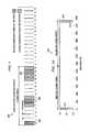
- FIG. 3is a schematic timing diagram of a PPM calibration symbol
- FIG. 3Ais a schematic timing diagram of two consecutive data symbols
- FIGS. 4-9are schematic flow diagrams representing the operation of the calibration/reload function illustrated in FIG. 2;
- FIG. 10is a truth table for N of 8 function.
- FIG. 11is a table of values of the bit window counter and bit down counter for which the calibration start function evaluates true for a given current calibration code.
- the present inventionis an RFID tag device comprising a circuit that calculates the relative frequency relationship between an internal oscillator of the RFID tag device and an external PPM source such as a RFID tag reader, and then calibrates the RFID tag device PPM decoder circuit to the required precision for reliable PPM symbol decoding.
- the PPM decoderis calibrated to the difference between the external PPM frequency source (i.e., RFID tag reader) and the internal oscillator of the RFID tag device, which is performed in a single measurement during one code violating calibration symbol period (hereinafter calibration symbol period).
- a transmitter—PPM modulator portion of an RFID tag readeris indicated generally by the numeral 102 and comprises a transmitter 104 and a PPM modulator 106 for modulating the radio frequency (RF) or electromagnetic transmission 108 from the transmitter 104 .
- a receiver-decoder portion of an RFID tag deviceis indicated generally by the numeral 110 and comprises a PPM modulation detector 114 , an internal oscillator 112 , a PPM decoder 116 , and symbol data 118 . It is contemplated and within the scope of the present invention that the RFID tag device 110 may be fabricated on a single semiconductor integrated circuit die (not illustrated) and produced in a number of different integrated circuit packages (not illustrated).
- commands, data, etc.(hereinafter information) is transferred to the RFID tag device 110 over the transmission 108 from the transmitter 104 which is modulated by the PPM modulator 106 .
- the informationis applied to the PPM modulator 106 along with a clock source (not illustrated) that is part of the RFID tag reader 102 .
- This informationis received by the PPM modulation detector 114 of the RFID tag device 110 , and is decoded by the PPM decoder 116 .
- the PPM decoder 116uses the internal oscillator 112 for timing functions in the PPM decoding process to produce the symbol data 118 .
- the timing of the internal oscillator 112must be calibrated with the PPM pulse timing or frequency detected so as to accurately decode the PPM information in the transmission 108 .
- the PPM decoder 116may be implemented as a state machine or in other ways known to those skilled in the art of digital logic circuits
- the PPM decoder 116comprises a synchronizer 120 , a PPM decoder state machine 122 , a calibration/reload function 124 , a bit down counter 126 , a bit window counter 128 , and a symbol register 130 .
- the synchronizer 120receives the detected PPM signal from the PPM modulation detector 114 .
- the PPM decoder 116tracks the state of the transmission 108 . On power up and during operation of the RFID tag device 110 , the PPM decoder 116 expects the transmission of code violating calibration symbols (see FIG. 3 ).
- the internal oscillator 112is used as a clock for the synchronizer 120 , the PPM decoder state machine 122 , the calibration/reload function 124 , the bit down counter 126 , and the bit window counter 128 .
- the PPM decoder state machine 122controls operation of the calibration/reload function 124 , the bit down counter 126 , and the bit window counter 128 . After decoding of the PPM symbol, the symbol data is available at the output of the symbol register 130 .
- the calibration/reload function 124comprises a calibration counter controller 210 , a calibration counter 212 , a calibration code register 208 , a reload register 206 , an N of 8 function 214 , an increment by 1 function 220 , a load fixed value 5 16 function 218 , and a multiplexer 216 .
- the calibration counter controller 210receives the detected PPM signal from the PPM modulation detector 114 .
- the calibration symbolgenerally indicated by the numeral 300 , comprises three distinct PPM pulses transmitted within one symbol period.
- the symbol periodcomprises 16 time slots, and the three pulses are at time slot position 0 for the first pulse 302 , position 6 for the second pulse 304 , and position 14 for the third pulse 306 .
- Other number of time slots for a symbol period and number and positions for the calibration pulsesmay be used and are contemplated herein for the present invention.
- the time scale in FIG. 3is for illustration only and other time scales may be utilized depending on the configurations of the invention.
- first data symbolhas a pulse 312 at time slot 0 (symbol “ 0 ”) and the second data symbol has a pulse 314 at time slot 15 (symbol “F 16 ”).
- First data symbol 0 followed by second data symbol Frepresent a worst case scenario (maximum time separation between the two symbol pulses) for synchronizing the received PPM symbols and the internal oscillator 112 .
- Pulses 312 and 314are separated by 31 time slots (1 of 16 PPM). A PPM pulse is recognized on its rising edge as it exceeds a signal detection threshold.
- step 402the PPM decoder 116 is initialized, for example during start-up or power-on-reset, by the bit window counter 128 being reset to 0 16 (0000 b ) in step 404 .
- Step 406checks for the first PPM pulse 302 and keeps the bit window counter 128 in reset. Once the first PPM pulse 302 has been detected in step 406 , the bit down counter 126 is loaded with 5 16 (0101 b ) in step 408 .
- step 410the bit down counter 126 is decremented at each clock pulse of the internal oscillator 112 .
- Step 411checks for the second PPM pulse 304 , and if there is no PPM pulse 304 then step 412 checks if the bit down counter 126 is at 0 16 (0000 b ). If the bit down counter 126 is not at 0 16 (0000 b ) then step 410 continues to decrement the bit down counter 126 . If the bit down counter 126 is at 0 16 (0000 b ) then the steps in subroutine RELOAD_BDC 900 (see FIG. 9) reload the bit down counter 126 with the contents of the reload register 206 , and step 414 increments the bit window counter 128 .
- Step 415checks for overflow of the bit window counter 128 , if there is no overflow then step 410 again decrements the bit down counter 126 , and if there is overflow then step 404 resets the bit window counter 128 back to 0 16 (0000 b)
- step 552checks whether the contents of the bit window counter 128 is from 5 16 (0101 b ) to 7 16 (0111 b ). If not, then step 553 checks whether the contents of the bit window counter 128 is from 1 16 (0001 b ) to 2 16 (0010 b ). If the contents of the bit window counter 128 is from 1 16 (0001 b ) to 2 16 (0010 b ) then step 553 a determines that a fast read command decode be used. If the contents of the bit window counter 128 is not from 1 16 (0001 b ) to 2 16 (0010 b ) then step 404 resets the bit window counter 128 to 0 16 (0000 b ).
- step 552determines that the contents of the bit window counter 128 is from 5 16 (0101 b ) to 7 16 (0111 b )
- step 554loads 6 16 (0110 b ) into the bit window counter 128
- step 560loads 5 16 (0101 b ) into the bit down counter 126 .
- Step 562decrements the bit down counter 126 at each clock pulse of the internal oscillator 112 .
- Step 564checks for a third PPM pulse 306 , and if the third PPM pulse 306 is detected then step 604 checks whether the contents of the bit window counter 128 is from C 16 (1100 b ) to F 16 (1111 b ), if not then step 404 resets the bit window counter 128 back to 0 16 (0000 b ) as described above.
- step 566checks if the contents of the bit down counter 126 is 0 16 (0000 b ). If no then step 562 resumes decrementing the bit down counter 126 , and if yes then the steps in subroutine RELOAD_BDC 900 (see FIG. 9) reload the bit down counter 126 with the contents of the reload register 206 . Step 570 then checks whether the contents of the bit window counter 128 is F 16 (1111 b ), if no then step 572 increments the bit window counter 128 and step 562 decrements the bit down counter 126 as described above. When step 570 determines that the contents of the bit window counter 128 is F 16 (1111 b ), then step 404 resets the bit window counter 128 to 0 16 (0000 b ) as described above.
- Step 802determines whether a calibration start function is true (see table 2 of FIG. 11 ).
- step 804increments the calibration counter 212 at each clock pulse of the internal oscillator 112 .
- Step 806determines when the third PPM pulse 306 is detected. If the third PPM pulse 306 is not detected then step 810 determines if the calibration counter 212 is equal to 2F 16 (0010 1111 b ), and if not, then step 804 increments the calibration counter 212 .
- step 810determines that the calibration counter 212 is equal to 2F 16 (0010 1111 b ) then step 812 stops the calibration counter 212 and returns operation back to step 564 (see FIG. 5 ).
- step 806detects the third PPM pulse 306
- step 808stops the calibration counter 212 and returns operation back to step 604 .
- step 604determines that the contents of the bit window counter 128 is from C 16 (1100 b ) to F 16 (1111 b ), then a PPM code violating calibration symbol 300 is recognized in step 606 . Then step 608 loads E 16 (1110 b ) into the bit window counter 128 , step 610 loads 5 16 (0101 b ) into the bit down counter 126 , and step 612 loads the value of the calibration counter 212 into the calibration code register 208 . Step 614 decrements the bit down counter at each clock pulse of the internal oscillator 112 .
- Step 615checks for another PPM pulse, and if a PPM pulse is detected then step 404 resets the bit window counter 128 back to 0 16 (0000 b ) If a PPM pulse is not detected in step 615 then step 616 determines whether the contents of the bit down counter 126 is 0 16 (0000 b ) If no, then step 614 decrements the bit down counter at each clock pulse of the internal oscillator 112 . If yes, then the steps in subroutine RELOAD_BDC 900 (see FIG. 9) reload the bit down counter 126 with the contents of the reload register 206 .
- Step 618increments the bit window counter 128 and then step 620 checks whether the contents of the bit window counter 128 is 0 16 (0000 b ). If no then step 614 decrements the bit down counter 126 at each clock pulse of the internal oscillator 112 , and step 616 determines whether the contents of the bit down counter is 0 16 (0000 b ) as described above.
- step 620determines that the contents of the bit window counter 128 is 0 16 (0000 b ) then step 622 starts PPM symbol reception.
- step 702decrements the bit down counter 126 at each clock pulse of the internal oscillator 112 .
- Step 704checks for a PPM pulse, if a PPM pulse is detected then step 710 loads 5 16 (01001 b ) into the bit down counter 126 and step 712 decodes the 1 of 16 PPM symbol value with the bit window counter 128 .
- step 706determines whether the contents of the bit down counter is 0 16 (0000 b ). If no, step 702 decrements the bit down counter 126 at each clock pulse of the internal oscillator 112 as described above. If yes, then the steps in subroutine RELOAD_BDC 900 (see FIG. 9) reload the bit down counter 126 with the contents of the reload register 206 . Then step 708 increments the bit window counter 128 and step 702 decrements the bit down counter 126 at each clock pulse of the internal oscillator 112 , as led described above.
- the reception to the 3 rd bit of the calibration symbol(modulation pulse 306 ) will occur when the values in the bit window counter 128 equals E 16 and the bit down counter 126 equals 5 16 , respectively. Under these conditions the value in the calibration counter 212 will always equal the value in the calibration code register 208 .
- the difference between the old value of the calibration code register 208 and a new valuerepresents the accumulated error in clock cycles over 8 bits times. For example, if the difference between the old value and the new value of the calibration code register 208 is one then the accumulated calibration error is one count in 8 bit periods or 1 ⁇ 8 th of a clock per bit period.
- This examplerepresents the precision of this embodiment of the present invention.
- the level of precision that is preferred in this embodimentis determined by the worst case transmission, illustrated in FIG. 3A, which is the symbol 0 16 followed by the symbol F 16
- the spacing between a symbol 0 16 and a symbol F 16is 31 bit periods. Therefore the worst case accumulated error at the given precision would be plus or minus 31 ⁇ 8 ths or approximately 4 for a total window error of less than 8.
- the worst case erroris less than the number of counts in the bit period.
- subroutine RELOAD_BDCis generally indicated by the numeral 900 .
- step 902starts this subroutine and step 904 determines whether the N of 8 function is true.
- Table 1 of FIG. 10contains the truth table of step 904 , according to an embodiment of the invention.
- step 904determines that the N of 8 function is, true (FIG. 10) then step 906 reloads the bit down counter 126 with the contents of the reload register 206 plus one (see also FIG. 2 ).
- step 908reloads the bit down counter 126 with only the contents of the reload register 206 .
- the step 910returns back to the aforementioned steps from the steps of subroutine RELOAD_BDC 900 .
- bit window counter 128BWC 16
- bit down counter 126BDC 16
Landscapes
- Engineering & Computer Science (AREA)
- Computer Networks & Wireless Communication (AREA)
- Theoretical Computer Science (AREA)
- Microelectronics & Electronic Packaging (AREA)
- Physics & Mathematics (AREA)
- General Physics & Mathematics (AREA)
- Computer Hardware Design (AREA)
- Signal Processing (AREA)
- Synchronisation In Digital Transmission Systems (AREA)
- Radar Systems Or Details Thereof (AREA)
- Stabilization Of Oscillater, Synchronisation, Frequency Synthesizers (AREA)
- Arrangements For Transmission Of Measured Signals (AREA)
- Testing Or Calibration Of Command Recording Devices (AREA)
Abstract
Description
Claims (11)
Priority Applications (9)
| Application Number | Priority Date | Filing Date | Title |
|---|---|---|---|
| US09/602,291US6687293B1 (en) | 2000-06-23 | 2000-06-23 | Method, system and apparatus for calibrating a pulse position modulation (PPM) decoder to a PPM signal |
| AU2001268573AAU2001268573A1 (en) | 2000-06-23 | 2001-06-20 | Method, system and apparatus for calibrating a pulse position modulation (ppm) decoder to a ppm signal |
| KR1020027002324AKR20020048390A (en) | 2000-06-23 | 2001-06-20 | Method, System and Apparatus for Calibrating a Pulse Position Modulation (PPM) Decoder to a PPM Signal |
| CN01802404ACN1388903A (en) | 2000-06-23 | 2001-06-20 | Method, system and apparatus for calibrating a pulse position modulation (PPM) decoder to a PPM signal |
| JP2002506127AJP2004502176A (en) | 2000-06-23 | 2001-06-20 | Method, system and apparatus for calibrating a pulse position modulation (PPM) decoder for a PPM signal |
| PCT/US2001/019599WO2002001246A2 (en) | 2000-06-23 | 2001-06-20 | Method, system and apparatus for calibrating a pulse position modulation (ppm) decoder to a ppm signal |
| EP01946540AEP1292846A2 (en) | 2000-06-23 | 2001-06-20 | Method, system and apparatus for calibrating a pulse position modulation (ppm) decoder to a ppm signal |
| ARP010102997AAR028748A1 (en) | 2000-06-23 | 2001-06-22 | METHOD, SYSTEM AND APPLIANCE FOR CALIBRATING A PULSE POSITION MODULATION DECODER (PPM) TO A PPM SIGNAL |
| TW090115281ATW536636B (en) | 2000-06-23 | 2001-06-22 | Method, system and apparatus for calibrating a pulse position modulation (PPM) decoder to a PPM signal |
Applications Claiming Priority (1)
| Application Number | Priority Date | Filing Date | Title |
|---|---|---|---|
| US09/602,291US6687293B1 (en) | 2000-06-23 | 2000-06-23 | Method, system and apparatus for calibrating a pulse position modulation (PPM) decoder to a PPM signal |
Publications (1)
| Publication Number | Publication Date |
|---|---|
| US6687293B1true US6687293B1 (en) | 2004-02-03 |
Family
ID=24410769
Family Applications (1)
| Application Number | Title | Priority Date | Filing Date |
|---|---|---|---|
| US09/602,291Expired - LifetimeUS6687293B1 (en) | 2000-06-23 | 2000-06-23 | Method, system and apparatus for calibrating a pulse position modulation (PPM) decoder to a PPM signal |
Country Status (9)
| Country | Link |
|---|---|
| US (1) | US6687293B1 (en) |
| EP (1) | EP1292846A2 (en) |
| JP (1) | JP2004502176A (en) |
| KR (1) | KR20020048390A (en) |
| CN (1) | CN1388903A (en) |
| AR (1) | AR028748A1 (en) |
| AU (1) | AU2001268573A1 (en) |
| TW (1) | TW536636B (en) |
| WO (1) | WO2002001246A2 (en) |
Cited By (31)
| Publication number | Priority date | Publication date | Assignee | Title |
|---|---|---|---|---|
| US20040161051A1 (en)* | 2003-02-18 | 2004-08-19 | Weimin Sun | System and method of efficiently modulating data using symbols having more than one pulse |
| US20040165677A1 (en)* | 2003-02-24 | 2004-08-26 | Sheng Shen | Method and system to efficiently modulate data while reducing DC drift |
| US20050040974A1 (en)* | 2001-02-12 | 2005-02-24 | Shanks Wayne E. | Method, system, and apparatus for remote data calibration of a RFID tag population |
| US20050240370A1 (en)* | 2004-04-13 | 2005-10-27 | Diorio Christopher J | Method and system to calibrate an oscillator within an RFID circuit by selecting a calibration value from a plurality of stored calibration values |
| US20050243030A1 (en)* | 2004-04-29 | 2005-11-03 | Sang-Hyuck Ahn | Electron emission display and driving method thereof |
| US20060001585A1 (en)* | 2004-07-01 | 2006-01-05 | Omron Corporation | Antenna, tag communication apparatus, tag communication system, scanning adjusting method for tag communication apparatus and computer readable medium |
| US20060022826A1 (en)* | 2004-07-29 | 2006-02-02 | Omnicell, Inc. | Method and apparatus for preparing an item with an RFID tag |
| US20060022797A1 (en)* | 1997-12-24 | 2006-02-02 | Murdoch Graham A M | Transmitter and a method for transmitting data |
| US20060083294A1 (en)* | 2004-10-14 | 2006-04-20 | Philip Orlik | Modulating signals for coherent and differentially coherent receivers |
| US20060097873A1 (en)* | 2004-11-10 | 2006-05-11 | Rockwell Automation Technologies, Inc. | Systems and methods that integrate radio frequency identification (RFID) technology with agent-based control systems |
| US20060108411A1 (en)* | 2004-11-10 | 2006-05-25 | Rockwell Automation Technologies, Inc. | Systems and methods that integrate radio frequency identification (RFID) technology with industrial controllers |
| US20060161367A1 (en)* | 2003-02-07 | 2006-07-20 | Koninklijke Philips Electronics N.V. | System and method for calibrating the clock frequency of a clock generator unit over a data line |
| US20060203931A1 (en)* | 2005-03-07 | 2006-09-14 | Philip Orlik | M-ary modulation of signals for coherent and differentially coherent receivers |
| US20060238356A1 (en)* | 2005-04-26 | 2006-10-26 | Cooper Tire & Rubber Company | RFID transmitter for tires and method of manufacture |
| US20070018820A1 (en)* | 2005-07-20 | 2007-01-25 | Rockwell Automation Technologies, Inc. | Mobile RFID reader with integrated location awareness for material tracking and management |
| US20070018819A1 (en)* | 2005-07-19 | 2007-01-25 | Propack Data G.M.B.H | Reconciliation mechanism using RFID and sensors |
| US20070024463A1 (en)* | 2005-07-26 | 2007-02-01 | Rockwell Automation Technologies, Inc. | RFID tag data affecting automation controller with internal database |
| US20070035396A1 (en)* | 2005-08-10 | 2007-02-15 | Rockwell Automation Technologies, Inc. | Enhanced controller utilizing RFID technology |
| US20070052540A1 (en)* | 2005-09-06 | 2007-03-08 | Rockwell Automation Technologies, Inc. | Sensor fusion for RFID accuracy |
| US20070055470A1 (en)* | 2005-09-08 | 2007-03-08 | Rockwell Automation Technologies, Inc. | RFID architecture in an industrial controller environment |
| US20070063029A1 (en)* | 2005-09-20 | 2007-03-22 | Rockwell Automation Technologies, Inc. | RFID-based product manufacturing and lifecycle management |
| US20070075832A1 (en)* | 2005-09-30 | 2007-04-05 | Rockwell Automation Technologies, Inc. | RFID reader with programmable I/O control |
| US20070075128A1 (en)* | 2005-09-30 | 2007-04-05 | Rockwell Automation Technologies, Inc. | Access to distributed databases via pointer stored in RFID tag |
| US20070285244A1 (en)* | 2006-04-28 | 2007-12-13 | Cooper Tire & Rubber Co. | Long range RFID transponder |
| US20070296283A1 (en)* | 2006-06-22 | 2007-12-27 | Cooper Tire & Rubber Co. | Magnetostrictive / piezo remote power generation, battery and method |
| US20080247442A1 (en)* | 2005-07-18 | 2008-10-09 | Orlik Philip V | Method, Apparatus, and System for Modulating and Demodulating Signals Compatible with Multiple Receiver Types and Designed for Improved Receiver Performance |
| US7446662B1 (en) | 2005-09-26 | 2008-11-04 | Rockwell Automation Technologies, Inc. | Intelligent RFID tag for magnetic field mapping |
| US7636044B1 (en) | 2005-05-13 | 2009-12-22 | Rockwell Automation Technologies, Inc. | RFID tag programming, printing application, and supply chain/global registration architecture |
| CN101145896B (en)* | 2007-09-17 | 2010-11-03 | 浙江中控技术股份有限公司 | Control system and method for clock synchronization between control stations |
| CN104467763A (en)* | 2014-11-19 | 2015-03-25 | 天津光电通信技术有限公司 | Multiplexed output synchronization pulse control system |
| US11075743B2 (en)* | 2019-08-27 | 2021-07-27 | Nxp Usa, Inc. | Adjustable high resolution timer |
Families Citing this family (9)
| Publication number | Priority date | Publication date | Assignee | Title |
|---|---|---|---|---|
| WO2002054365A1 (en)* | 2000-12-29 | 2002-07-11 | Tagsys Australia Pty Ltd | A system and method for interrogating electronic labels |
| US6946951B2 (en) | 2000-12-29 | 2005-09-20 | Tagsys Australia Pty Ltd. | System and method for interrogating electronic labels |
| US7672513B2 (en) | 2003-04-29 | 2010-03-02 | Anoto Ab | Methods, apparatus, computer program and storage medium for position decoding |
| DE10334904B3 (en)* | 2003-07-29 | 2005-05-19 | Zentrum Mikroelektronik Dresden Ag | Method and arrangement for generating a time base in a transponder |
| TWI334576B (en)* | 2006-12-05 | 2010-12-11 | Ind Tech Res Inst | Method and system for reading rfid tags |
| CN100428263C (en)* | 2006-12-15 | 2008-10-22 | 清华大学 | RF card or RF tag based on UWB wireless pulse mode |
| CN102215089B (en)* | 2011-05-26 | 2013-08-21 | 王红星 | Wireless optical communication pulse position modulation detection and demodulation method based on least posterior error probability |
| CN103634003B (en)* | 2012-08-14 | 2016-02-10 | 上海华虹宏力半导体制造有限公司 | OSC frequency automatic calibration circuit and automatic calibrating method |
| CN108768517B (en)* | 2018-04-19 | 2020-03-10 | 华南师范大学 | PPM-based sending end, receiving end and visible light communication system |
Citations (10)
| Publication number | Priority date | Publication date | Assignee | Title |
|---|---|---|---|---|
| US3575665A (en) | 1967-06-15 | 1971-04-20 | Nippon Electric Co | Asynchronous demodulation system for pulse position modulation signal utilizing phase or frequency modulated higher harmonic of a sampling frequency |
| US4384288A (en) | 1980-12-31 | 1983-05-17 | Walton Charles A | Portable radio frequency emitting identifier |
| USRE31254E (en) | 1978-08-28 | 1983-05-24 | Sanders Associates, Inc. | Self calibration of a LORAN-C navigation receiver |
| US4555702A (en)* | 1981-09-17 | 1985-11-26 | Hitachi, Ltd. | Remote control signal reproducing circuit |
| US4648133A (en) | 1984-08-07 | 1987-03-03 | The Unites States Of America As Represented By The Administrator Of The National Aeronautics And Space Administration | Synchronization tracking in pulse position modulation receiver |
| US4742470A (en)* | 1985-12-30 | 1988-05-03 | Gte Valeron Corporation | Tool identification system |
| DE4003410A1 (en)* | 1990-02-05 | 1991-08-08 | Anatoli Stobbe | PORTABLE FIELD PROGRAMMABLE DETECTOR TAG |
| US5354319A (en) | 1990-01-22 | 1994-10-11 | Medtronic, Inc. | Telemetry system for an implantable medical device |
| WO2002005504A1 (en)* | 2000-07-06 | 2002-01-17 | Microchip Technology Incorporated | Method, system and apparatus for initiating and maintaining synchronization of a pulse position modulation (ppm) decoder with a received ppm signal |
| US6434194B1 (en)* | 1997-11-05 | 2002-08-13 | Wherenet Corp | Combined OOK-FSK/PPM modulation and communication protocol scheme providing low cost, low power consumption short range radio link |
- 2000
- 2000-06-23USUS09/602,291patent/US6687293B1/ennot_activeExpired - Lifetime
- 2001
- 2001-06-20JPJP2002506127Apatent/JP2004502176A/ennot_activeWithdrawn
- 2001-06-20KRKR1020027002324Apatent/KR20020048390A/ennot_activeWithdrawn
- 2001-06-20EPEP01946540Apatent/EP1292846A2/ennot_activeWithdrawn
- 2001-06-20WOPCT/US2001/019599patent/WO2002001246A2/ennot_activeApplication Discontinuation
- 2001-06-20AUAU2001268573Apatent/AU2001268573A1/ennot_activeAbandoned
- 2001-06-20CNCN01802404Apatent/CN1388903A/enactivePending
- 2001-06-22ARARP010102997Apatent/AR028748A1/enunknown
- 2001-06-22TWTW090115281Apatent/TW536636B/enactive
Patent Citations (10)
| Publication number | Priority date | Publication date | Assignee | Title |
|---|---|---|---|---|
| US3575665A (en) | 1967-06-15 | 1971-04-20 | Nippon Electric Co | Asynchronous demodulation system for pulse position modulation signal utilizing phase or frequency modulated higher harmonic of a sampling frequency |
| USRE31254E (en) | 1978-08-28 | 1983-05-24 | Sanders Associates, Inc. | Self calibration of a LORAN-C navigation receiver |
| US4384288A (en) | 1980-12-31 | 1983-05-17 | Walton Charles A | Portable radio frequency emitting identifier |
| US4555702A (en)* | 1981-09-17 | 1985-11-26 | Hitachi, Ltd. | Remote control signal reproducing circuit |
| US4648133A (en) | 1984-08-07 | 1987-03-03 | The Unites States Of America As Represented By The Administrator Of The National Aeronautics And Space Administration | Synchronization tracking in pulse position modulation receiver |
| US4742470A (en)* | 1985-12-30 | 1988-05-03 | Gte Valeron Corporation | Tool identification system |
| US5354319A (en) | 1990-01-22 | 1994-10-11 | Medtronic, Inc. | Telemetry system for an implantable medical device |
| DE4003410A1 (en)* | 1990-02-05 | 1991-08-08 | Anatoli Stobbe | PORTABLE FIELD PROGRAMMABLE DETECTOR TAG |
| US6434194B1 (en)* | 1997-11-05 | 2002-08-13 | Wherenet Corp | Combined OOK-FSK/PPM modulation and communication protocol scheme providing low cost, low power consumption short range radio link |
| WO2002005504A1 (en)* | 2000-07-06 | 2002-01-17 | Microchip Technology Incorporated | Method, system and apparatus for initiating and maintaining synchronization of a pulse position modulation (ppm) decoder with a received ppm signal |
Non-Patent Citations (1)
| Title |
|---|
| International Search Report for PCT/US01/19599, 6 pages, Dec. 27, 2001. |
Cited By (75)
| Publication number | Priority date | Publication date | Assignee | Title |
|---|---|---|---|---|
| US20060022797A1 (en)* | 1997-12-24 | 2006-02-02 | Murdoch Graham A M | Transmitter and a method for transmitting data |
| US7978073B2 (en)* | 1997-12-24 | 2011-07-12 | Magellan Technology Pty Limited | Transmitter and a method for transmitting data |
| US7145482B2 (en)* | 2001-02-12 | 2006-12-05 | Symbol Technologies, Inc. | Method, system, and apparatus for remote data calibration of a RFID tag population |
| US20050040974A1 (en)* | 2001-02-12 | 2005-02-24 | Shanks Wayne E. | Method, system, and apparatus for remote data calibration of a RFID tag population |
| US7928843B2 (en) | 2001-02-12 | 2011-04-19 | Symbol Technologies, Inc. | Method, system, and apparatus for communications in a RFID system |
| US7965189B2 (en) | 2001-02-12 | 2011-06-21 | Symbol Technologies, Inc. | Radio frequency identification architecture |
| US6956509B2 (en)* | 2001-02-12 | 2005-10-18 | Symbol Technologies, Inc. | Method, system, and apparatus for remote data calibration of a RFID tag population |
| US20060077082A1 (en)* | 2001-02-12 | 2006-04-13 | Symbol Technologies, Inc. | Method, system, and apparatus for remote data calibration of a RFID tag population |
| US7243036B2 (en)* | 2003-02-07 | 2007-07-10 | Nxp B.V. | System and method for calibrating the clock frequency of a clock generator unit over a data line |
| US20060161367A1 (en)* | 2003-02-07 | 2006-07-20 | Koninklijke Philips Electronics N.V. | System and method for calibrating the clock frequency of a clock generator unit over a data line |
| US7453950B2 (en)* | 2003-02-18 | 2008-11-18 | Intel Corporation | System and method of efficiently modulating data using symbols having more than one pulse |
| US20040161051A1 (en)* | 2003-02-18 | 2004-08-19 | Weimin Sun | System and method of efficiently modulating data using symbols having more than one pulse |
| US20040165677A1 (en)* | 2003-02-24 | 2004-08-26 | Sheng Shen | Method and system to efficiently modulate data while reducing DC drift |
| US8224610B2 (en) | 2004-04-13 | 2012-07-17 | Impinj, Inc. | Radio-frequency identification tag with oscillator calibration |
| US7120550B2 (en)* | 2004-04-13 | 2006-10-10 | Impinj, Inc. | Radio-frequency identification circuit oscillator calibration |
| US20070001856A1 (en)* | 2004-04-13 | 2007-01-04 | Diorio Christopher J | Radio-frequency identification tag with oscillator calibration |
| US20050240370A1 (en)* | 2004-04-13 | 2005-10-27 | Diorio Christopher J | Method and system to calibrate an oscillator within an RFID circuit by selecting a calibration value from a plurality of stored calibration values |
| US20050243030A1 (en)* | 2004-04-29 | 2005-11-03 | Sang-Hyuck Ahn | Electron emission display and driving method thereof |
| KR100704101B1 (en) | 2004-07-01 | 2007-04-06 | 오므론 가부시키가이샤 | Recording medium recording antenna for tag communication, tag communication device, tag communication system, scan adjustment method of tag communication device, and scan adjustment program |
| EP1681582A3 (en)* | 2004-07-01 | 2006-08-16 | Omron Corporation | RFID tag communication apparatus comprising a scanning beam antenna |
| US20060001585A1 (en)* | 2004-07-01 | 2006-01-05 | Omron Corporation | Antenna, tag communication apparatus, tag communication system, scanning adjusting method for tag communication apparatus and computer readable medium |
| US7724140B2 (en) | 2004-07-01 | 2010-05-25 | Omron Corporation | Antenna, tag communication apparatus, tag communication system, scanning adjusting method for tag communication apparatus and computer readable medium |
| US20060022826A1 (en)* | 2004-07-29 | 2006-02-02 | Omnicell, Inc. | Method and apparatus for preparing an item with an RFID tag |
| US7554449B2 (en) | 2004-07-29 | 2009-06-30 | Omnicell, Inc. | Method and apparatus for preparing an item with an RFID tag |
| US20070285242A1 (en)* | 2004-07-29 | 2007-12-13 | Omnicell, Inc. | Method and apparatus for preparing an item with an rfid tag |
| US7218231B2 (en) | 2004-07-29 | 2007-05-15 | Omnicell, Inc. | Method and apparatus for preparing an item with an RFID tag |
| US20060083294A1 (en)* | 2004-10-14 | 2006-04-20 | Philip Orlik | Modulating signals for coherent and differentially coherent receivers |
| US7391802B2 (en)* | 2004-10-14 | 2008-06-24 | Mitsubishi Electric Research Laboratories | Modulating signals for coherent and differentially coherent receivers |
| US20060097873A1 (en)* | 2004-11-10 | 2006-05-11 | Rockwell Automation Technologies, Inc. | Systems and methods that integrate radio frequency identification (RFID) technology with agent-based control systems |
| US20090243808A1 (en)* | 2004-11-10 | 2009-10-01 | Rockwell Automation Technologies, Inc. | Systems and methods that integrate radio frequency identification (rfid) technology with agent-based control systems |
| US20090254199A1 (en)* | 2004-11-10 | 2009-10-08 | Rockwell Automation Technologies, Inc. | Systems and methods that integrate radio frequency identification (rfid) technology with agent-based control systems |
| US7994919B2 (en) | 2004-11-10 | 2011-08-09 | Rockwell Automation Technologies, Inc. | Systems and methods that integrate radio frequency identification (RFID) technology with agent-based control systems |
| US7997475B2 (en) | 2004-11-10 | 2011-08-16 | Rockwell Automation Technologies, Inc. | Systems and methods that integrate radio frequency identification (RFID) technology with industrial controllers |
| US7551081B2 (en) | 2004-11-10 | 2009-06-23 | Rockwell Automation Technologies, Inc. | Systems and methods that integrate radio frequency identification (RFID) technology with agent-based control systems |
| US8384544B2 (en) | 2004-11-10 | 2013-02-26 | Rockwell Automation Technologies, Inc. | Systems and methods that integrate radio frequency identification (RFID) technology with agent-based control systems |
| US7339476B2 (en) | 2004-11-10 | 2008-03-04 | Rockwell Automation Technologies, Inc. | Systems and methods that integrate radio frequency identification (RFID) technology with industrial controllers |
| US20060108411A1 (en)* | 2004-11-10 | 2006-05-25 | Rockwell Automation Technologies, Inc. | Systems and methods that integrate radio frequency identification (RFID) technology with industrial controllers |
| US7388927B2 (en)* | 2005-03-07 | 2008-06-17 | Mitsubishi Electric Research Laboratories, Inc. | M-ary modulation of signals for coherent and differentially coherent receivers |
| US20060203931A1 (en)* | 2005-03-07 | 2006-09-14 | Philip Orlik | M-ary modulation of signals for coherent and differentially coherent receivers |
| US20060238356A1 (en)* | 2005-04-26 | 2006-10-26 | Cooper Tire & Rubber Company | RFID transmitter for tires and method of manufacture |
| US7504947B2 (en) | 2005-04-26 | 2009-03-17 | Cooper Tire & Rubber Company | RFID transmitter for tires and method of manufacture |
| US7636044B1 (en) | 2005-05-13 | 2009-12-22 | Rockwell Automation Technologies, Inc. | RFID tag programming, printing application, and supply chain/global registration architecture |
| US20080247442A1 (en)* | 2005-07-18 | 2008-10-09 | Orlik Philip V | Method, Apparatus, and System for Modulating and Demodulating Signals Compatible with Multiple Receiver Types and Designed for Improved Receiver Performance |
| US20070018819A1 (en)* | 2005-07-19 | 2007-01-25 | Propack Data G.M.B.H | Reconciliation mechanism using RFID and sensors |
| US7616117B2 (en) | 2005-07-19 | 2009-11-10 | Rockwell Automation Technologies, Inc. | Reconciliation mechanism using RFID and sensors |
| US7932827B2 (en) | 2005-07-20 | 2011-04-26 | Rockwell Automation Technologies, Inc. | Mobile RFID reader with integrated location awareness for material tracking and management |
| US20070018820A1 (en)* | 2005-07-20 | 2007-01-25 | Rockwell Automation Technologies, Inc. | Mobile RFID reader with integrated location awareness for material tracking and management |
| US7388491B2 (en) | 2005-07-20 | 2008-06-17 | Rockwell Automation Technologies, Inc. | Mobile RFID reader with integrated location awareness for material tracking and management |
| US20070024463A1 (en)* | 2005-07-26 | 2007-02-01 | Rockwell Automation Technologies, Inc. | RFID tag data affecting automation controller with internal database |
| US7764191B2 (en) | 2005-07-26 | 2010-07-27 | Rockwell Automation Technologies, Inc. | RFID tag data affecting automation controller with internal database |
| US20070035396A1 (en)* | 2005-08-10 | 2007-02-15 | Rockwell Automation Technologies, Inc. | Enhanced controller utilizing RFID technology |
| US8260948B2 (en) | 2005-08-10 | 2012-09-04 | Rockwell Automation Technologies, Inc. | Enhanced controller utilizing RFID technology |
| US20070052540A1 (en)* | 2005-09-06 | 2007-03-08 | Rockwell Automation Technologies, Inc. | Sensor fusion for RFID accuracy |
| US8152053B2 (en) | 2005-09-08 | 2012-04-10 | Rockwell Automation Technologies, Inc. | RFID architecture in an industrial controller environment |
| US7510110B2 (en) | 2005-09-08 | 2009-03-31 | Rockwell Automation Technologies, Inc. | RFID architecture in an industrial controller environment |
| US20070055470A1 (en)* | 2005-09-08 | 2007-03-08 | Rockwell Automation Technologies, Inc. | RFID architecture in an industrial controller environment |
| US20070063029A1 (en)* | 2005-09-20 | 2007-03-22 | Rockwell Automation Technologies, Inc. | RFID-based product manufacturing and lifecycle management |
| US7931197B2 (en) | 2005-09-20 | 2011-04-26 | Rockwell Automation Technologies, Inc. | RFID-based product manufacturing and lifecycle management |
| US7772978B1 (en) | 2005-09-26 | 2010-08-10 | Rockwell Automation Technologies, Inc. | Intelligent RFID tag for magnetic field mapping |
| US7446662B1 (en) | 2005-09-26 | 2008-11-04 | Rockwell Automation Technologies, Inc. | Intelligent RFID tag for magnetic field mapping |
| US20070075128A1 (en)* | 2005-09-30 | 2007-04-05 | Rockwell Automation Technologies, Inc. | Access to distributed databases via pointer stored in RFID tag |
| US8025227B2 (en) | 2005-09-30 | 2011-09-27 | Rockwell Automation Technologies, Inc. | Access to distributed databases via pointer stored in RFID tag |
| US20070075832A1 (en)* | 2005-09-30 | 2007-04-05 | Rockwell Automation Technologies, Inc. | RFID reader with programmable I/O control |
| US7443301B2 (en) | 2006-04-28 | 2008-10-28 | Cooper Tire & Rubber Co. | Long range RFID transponder |
| US20070285244A1 (en)* | 2006-04-28 | 2007-12-13 | Cooper Tire & Rubber Co. | Long range RFID transponder |
| US20090167115A1 (en)* | 2006-06-22 | 2009-07-02 | Cooper Tire & Rubber Company | Magnetostrictive / piezo remote power generation, battery and method |
| US20090218914A1 (en)* | 2006-06-22 | 2009-09-03 | Cooper Tire & Rubber Company | Magnetostrictive / piezo remote power generation, battery and method |
| US7804229B2 (en) | 2006-06-22 | 2010-09-28 | Cooper Tire & Rubber Company | Magnetostrictive / piezo remote power generation, battery and method |
| US7521842B2 (en) | 2006-06-22 | 2009-04-21 | Cooper Tire & Rubber Co. | Magnetostrictive / piezo remote power generation, battery and method |
| US20070296283A1 (en)* | 2006-06-22 | 2007-12-27 | Cooper Tire & Rubber Co. | Magnetostrictive / piezo remote power generation, battery and method |
| US7808159B2 (en) | 2006-06-22 | 2010-10-05 | Cooper Tire & Rubber Company | Magnetostrictive / piezo remote power generation, battery and method |
| CN101145896B (en)* | 2007-09-17 | 2010-11-03 | 浙江中控技术股份有限公司 | Control system and method for clock synchronization between control stations |
| CN104467763A (en)* | 2014-11-19 | 2015-03-25 | 天津光电通信技术有限公司 | Multiplexed output synchronization pulse control system |
| CN104467763B (en)* | 2014-11-19 | 2017-06-06 | 天津光电通信技术有限公司 | Multiple-channel output synchronized-pulse control system |
| US11075743B2 (en)* | 2019-08-27 | 2021-07-27 | Nxp Usa, Inc. | Adjustable high resolution timer |
Also Published As
| Publication number | Publication date |
|---|---|
| JP2004502176A (en) | 2004-01-22 |
| CN1388903A (en) | 2003-01-01 |
| TW536636B (en) | 2003-06-11 |
| WO2002001246A2 (en) | 2002-01-03 |
| AU2001268573A1 (en) | 2002-01-08 |
| AR028748A1 (en) | 2003-05-21 |
| WO2002001246A3 (en) | 2002-04-04 |
| EP1292846A2 (en) | 2003-03-19 |
| KR20020048390A (en) | 2002-06-22 |
Similar Documents
| Publication | Publication Date | Title |
|---|---|---|
| US6687293B1 (en) | Method, system and apparatus for calibrating a pulse position modulation (PPM) decoder to a PPM signal | |
| US6700931B1 (en) | Method, system and apparatus for initiating and maintaining synchronization of a pulse position modulation (PPM) decoder with a received PPM signal | |
| AU670402B2 (en) | Synchronised electronic identification system | |
| CN109257072B (en) | Method, apparatus and system for clock synchronization | |
| US7986653B2 (en) | Wireless data transmission between base station and transponder with transmission parameter adjusted based on transponder operating information | |
| US8325786B2 (en) | Semiconductor device and communication device | |
| US7609147B2 (en) | Method and apparatus for improving wireless data transmission | |
| US20110170487A1 (en) | Method and Apparatus for Data Communication Between a Base Station and a Transponder | |
| US11099598B2 (en) | Phase alignment of a controller clock to a field | |
| US8988144B2 (en) | Demodulator and system for transmitting modulated information, in particular for radiofrequency identification tags | |
| US7613987B2 (en) | Method for wireless data transmission | |
| KR100771487B1 (en) | Method and apparatus for signal decoding in radio wave identification system | |
| JP3089962B2 (en) | Decoding device for two-phase encoded data | |
| US8766776B2 (en) | Transponder unit | |
| JP2005151033A (en) | Vpm modulation system in rfid communication | |
| US7675341B2 (en) | Method and device for generating a clock signal | |
| US20060192656A1 (en) | Transmission of data to or from transponder devices | |
| US20050219038A1 (en) | Method and system for contactless data transmission | |
| JP2000252856A (en) | Responder with external input |
Legal Events
| Date | Code | Title | Description |
|---|---|---|---|
| AS | Assignment | Owner name:MICROCHIP TECHNOLOGY INCORPORATED, ARIZONA Free format text:ASSIGNMENT OF ASSIGNORS INTEREST;ASSIGNORS:LOYER, STEPHEN R.;ALEXANDER, SAMUEL E.;REEL/FRAME:010934/0273;SIGNING DATES FROM 20000621 TO 20000622 | |
| STCF | Information on status: patent grant | Free format text:PATENTED CASE | |
| FPAY | Fee payment | Year of fee payment:4 | |
| FPAY | Fee payment | Year of fee payment:8 | |
| FPAY | Fee payment | Year of fee payment:12 | |
| AS | Assignment | Owner name:JPMORGAN CHASE BANK, N.A., AS ADMINISTRATIVE AGENT, ILLINOIS Free format text:SECURITY INTEREST;ASSIGNOR:MICROCHIP TECHNOLOGY INCORPORATED;REEL/FRAME:041675/0617 Effective date:20170208 Owner name:JPMORGAN CHASE BANK, N.A., AS ADMINISTRATIVE AGENT Free format text:SECURITY INTEREST;ASSIGNOR:MICROCHIP TECHNOLOGY INCORPORATED;REEL/FRAME:041675/0617 Effective date:20170208 | |
| AS | Assignment | Owner name:JPMORGAN CHASE BANK, N.A., AS ADMINISTRATIVE AGENT, ILLINOIS Free format text:SECURITY INTEREST;ASSIGNORS:MICROCHIP TECHNOLOGY INCORPORATED;SILICON STORAGE TECHNOLOGY, INC.;ATMEL CORPORATION;AND OTHERS;REEL/FRAME:046426/0001 Effective date:20180529 Owner name:JPMORGAN CHASE BANK, N.A., AS ADMINISTRATIVE AGENT Free format text:SECURITY INTEREST;ASSIGNORS:MICROCHIP TECHNOLOGY INCORPORATED;SILICON STORAGE TECHNOLOGY, INC.;ATMEL CORPORATION;AND OTHERS;REEL/FRAME:046426/0001 Effective date:20180529 | |
| AS | Assignment | Owner name:WELLS FARGO BANK, NATIONAL ASSOCIATION, AS NOTES COLLATERAL AGENT, CALIFORNIA Free format text:SECURITY INTEREST;ASSIGNORS:MICROCHIP TECHNOLOGY INCORPORATED;SILICON STORAGE TECHNOLOGY, INC.;ATMEL CORPORATION;AND OTHERS;REEL/FRAME:047103/0206 Effective date:20180914 Owner name:WELLS FARGO BANK, NATIONAL ASSOCIATION, AS NOTES C Free format text:SECURITY INTEREST;ASSIGNORS:MICROCHIP TECHNOLOGY INCORPORATED;SILICON STORAGE TECHNOLOGY, INC.;ATMEL CORPORATION;AND OTHERS;REEL/FRAME:047103/0206 Effective date:20180914 | |
| AS | Assignment | Owner name:JPMORGAN CHASE BANK, N.A., AS ADMINISTRATIVE AGENT, DELAWARE Free format text:SECURITY INTEREST;ASSIGNORS:MICROCHIP TECHNOLOGY INC.;SILICON STORAGE TECHNOLOGY, INC.;ATMEL CORPORATION;AND OTHERS;REEL/FRAME:053311/0305 Effective date:20200327 | |
| AS | Assignment | Owner name:MICROSEMI CORPORATION, CALIFORNIA Free format text:RELEASE BY SECURED PARTY;ASSIGNOR:JPMORGAN CHASE BANK, N.A, AS ADMINISTRATIVE AGENT;REEL/FRAME:053466/0011 Effective date:20200529 Owner name:ATMEL CORPORATION, ARIZONA Free format text:RELEASE BY SECURED PARTY;ASSIGNOR:JPMORGAN CHASE BANK, N.A, AS ADMINISTRATIVE AGENT;REEL/FRAME:053466/0011 Effective date:20200529 Owner name:SILICON STORAGE TECHNOLOGY, INC., ARIZONA Free format text:RELEASE BY SECURED PARTY;ASSIGNOR:JPMORGAN CHASE BANK, N.A, AS ADMINISTRATIVE AGENT;REEL/FRAME:053466/0011 Effective date:20200529 Owner name:MICROCHIP TECHNOLOGY INC., ARIZONA Free format text:RELEASE BY SECURED PARTY;ASSIGNOR:JPMORGAN CHASE BANK, N.A, AS ADMINISTRATIVE AGENT;REEL/FRAME:053466/0011 Effective date:20200529 Owner name:MICROSEMI STORAGE SOLUTIONS, INC., ARIZONA Free format text:RELEASE BY SECURED PARTY;ASSIGNOR:JPMORGAN CHASE BANK, N.A, AS ADMINISTRATIVE AGENT;REEL/FRAME:053466/0011 Effective date:20200529 | |
| AS | Assignment | Owner name:WELLS FARGO BANK, NATIONAL ASSOCIATION, MINNESOTA Free format text:SECURITY INTEREST;ASSIGNORS:MICROCHIP TECHNOLOGY INC.;SILICON STORAGE TECHNOLOGY, INC.;ATMEL CORPORATION;AND OTHERS;REEL/FRAME:053468/0705 Effective date:20200529 | |
| AS | Assignment | Owner name:WELLS FARGO BANK, NATIONAL ASSOCIATION, AS COLLATERAL AGENT, MINNESOTA Free format text:SECURITY INTEREST;ASSIGNORS:MICROCHIP TECHNOLOGY INCORPORATED;SILICON STORAGE TECHNOLOGY, INC.;ATMEL CORPORATION;AND OTHERS;REEL/FRAME:055671/0612 Effective date:20201217 | |
| AS | Assignment | Owner name:WELLS FARGO BANK, NATIONAL ASSOCIATION, AS NOTES COLLATERAL AGENT, MINNESOTA Free format text:SECURITY INTEREST;ASSIGNORS:MICROCHIP TECHNOLOGY INCORPORATED;SILICON STORAGE TECHNOLOGY, INC.;ATMEL CORPORATION;AND OTHERS;REEL/FRAME:057935/0474 Effective date:20210528 | |
| AS | Assignment | Owner name:MICROSEMI STORAGE SOLUTIONS, INC., ARIZONA Free format text:RELEASE BY SECURED PARTY;ASSIGNOR:JPMORGAN CHASE BANK, N.A., AS ADMINISTRATIVE AGENT;REEL/FRAME:059333/0222 Effective date:20220218 Owner name:MICROSEMI CORPORATION, ARIZONA Free format text:RELEASE BY SECURED PARTY;ASSIGNOR:JPMORGAN CHASE BANK, N.A., AS ADMINISTRATIVE AGENT;REEL/FRAME:059333/0222 Effective date:20220218 Owner name:ATMEL CORPORATION, ARIZONA Free format text:RELEASE BY SECURED PARTY;ASSIGNOR:JPMORGAN CHASE BANK, N.A., AS ADMINISTRATIVE AGENT;REEL/FRAME:059333/0222 Effective date:20220218 Owner name:SILICON STORAGE TECHNOLOGY, INC., ARIZONA Free format text:RELEASE BY SECURED PARTY;ASSIGNOR:JPMORGAN CHASE BANK, N.A., AS ADMINISTRATIVE AGENT;REEL/FRAME:059333/0222 Effective date:20220218 Owner name:MICROCHIP TECHNOLOGY INCORPORATED, ARIZONA Free format text:RELEASE BY SECURED PARTY;ASSIGNOR:JPMORGAN CHASE BANK, N.A., AS ADMINISTRATIVE AGENT;REEL/FRAME:059333/0222 Effective date:20220218 | |
| AS | Assignment | Owner name:MICROCHIP TECHNOLOGY INCORPORATED, ARIZONA Free format text:RELEASE BY SECURED PARTY;ASSIGNOR:JPMORGAN CHASE BANK, N.A., AS ADMINISTRATIVE AGENT;REEL/FRAME:059666/0545 Effective date:20220218 | |
| AS | Assignment | Owner name:MICROSEMI STORAGE SOLUTIONS, INC., ARIZONA Free format text:RELEASE BY SECURED PARTY;ASSIGNOR:WELLS FARGO BANK, NATIONAL ASSOCIATION, AS NOTES COLLATERAL AGENT;REEL/FRAME:059358/0001 Effective date:20220228 Owner name:MICROSEMI CORPORATION, ARIZONA Free format text:RELEASE BY SECURED PARTY;ASSIGNOR:WELLS FARGO BANK, NATIONAL ASSOCIATION, AS NOTES COLLATERAL AGENT;REEL/FRAME:059358/0001 Effective date:20220228 Owner name:ATMEL CORPORATION, ARIZONA Free format text:RELEASE BY SECURED PARTY;ASSIGNOR:WELLS FARGO BANK, NATIONAL ASSOCIATION, AS NOTES COLLATERAL AGENT;REEL/FRAME:059358/0001 Effective date:20220228 Owner name:SILICON STORAGE TECHNOLOGY, INC., ARIZONA Free format text:RELEASE BY SECURED PARTY;ASSIGNOR:WELLS FARGO BANK, NATIONAL ASSOCIATION, AS NOTES COLLATERAL AGENT;REEL/FRAME:059358/0001 Effective date:20220228 Owner name:MICROCHIP TECHNOLOGY INCORPORATED, ARIZONA Free format text:RELEASE BY SECURED PARTY;ASSIGNOR:WELLS FARGO BANK, NATIONAL ASSOCIATION, AS NOTES COLLATERAL AGENT;REEL/FRAME:059358/0001 Effective date:20220228 | |
| AS | Assignment | Owner name:MICROSEMI STORAGE SOLUTIONS, INC., ARIZONA Free format text:RELEASE BY SECURED PARTY;ASSIGNOR:WELLS FARGO BANK, NATIONAL ASSOCIATION, AS NOTES COLLATERAL AGENT;REEL/FRAME:059863/0400 Effective date:20220228 Owner name:MICROSEMI CORPORATION, ARIZONA Free format text:RELEASE BY SECURED PARTY;ASSIGNOR:WELLS FARGO BANK, NATIONAL ASSOCIATION, AS NOTES COLLATERAL AGENT;REEL/FRAME:059863/0400 Effective date:20220228 Owner name:ATMEL CORPORATION, ARIZONA Free format text:RELEASE BY SECURED PARTY;ASSIGNOR:WELLS FARGO BANK, NATIONAL ASSOCIATION, AS NOTES COLLATERAL AGENT;REEL/FRAME:059863/0400 Effective date:20220228 Owner name:SILICON STORAGE TECHNOLOGY, INC., ARIZONA Free format text:RELEASE BY SECURED PARTY;ASSIGNOR:WELLS FARGO BANK, NATIONAL ASSOCIATION, AS NOTES COLLATERAL AGENT;REEL/FRAME:059863/0400 Effective date:20220228 Owner name:MICROCHIP TECHNOLOGY INCORPORATED, ARIZONA Free format text:RELEASE BY SECURED PARTY;ASSIGNOR:WELLS FARGO BANK, NATIONAL ASSOCIATION, AS NOTES COLLATERAL AGENT;REEL/FRAME:059863/0400 Effective date:20220228 | |
| AS | Assignment | Owner name:MICROSEMI STORAGE SOLUTIONS, INC., ARIZONA Free format text:RELEASE BY SECURED PARTY;ASSIGNOR:WELLS FARGO BANK, NATIONAL ASSOCIATION, AS NOTES COLLATERAL AGENT;REEL/FRAME:059363/0001 Effective date:20220228 Owner name:MICROSEMI CORPORATION, ARIZONA Free format text:RELEASE BY SECURED PARTY;ASSIGNOR:WELLS FARGO BANK, NATIONAL ASSOCIATION, AS NOTES COLLATERAL AGENT;REEL/FRAME:059363/0001 Effective date:20220228 Owner name:ATMEL CORPORATION, ARIZONA Free format text:RELEASE BY SECURED PARTY;ASSIGNOR:WELLS FARGO BANK, NATIONAL ASSOCIATION, AS NOTES COLLATERAL AGENT;REEL/FRAME:059363/0001 Effective date:20220228 Owner name:SILICON STORAGE TECHNOLOGY, INC., ARIZONA Free format text:RELEASE BY SECURED PARTY;ASSIGNOR:WELLS FARGO BANK, NATIONAL ASSOCIATION, AS NOTES COLLATERAL AGENT;REEL/FRAME:059363/0001 Effective date:20220228 Owner name:MICROCHIP TECHNOLOGY INCORPORATED, ARIZONA Free format text:RELEASE BY SECURED PARTY;ASSIGNOR:WELLS FARGO BANK, NATIONAL ASSOCIATION, AS NOTES COLLATERAL AGENT;REEL/FRAME:059363/0001 Effective date:20220228 | |
| AS | Assignment | Owner name:MICROSEMI STORAGE SOLUTIONS, INC., ARIZONA Free format text:RELEASE BY SECURED PARTY;ASSIGNOR:WELLS FARGO BANK, NATIONAL ASSOCIATION, AS NOTES COLLATERAL AGENT;REEL/FRAME:060894/0437 Effective date:20220228 Owner name:MICROSEMI CORPORATION, ARIZONA Free format text:RELEASE BY SECURED PARTY;ASSIGNOR:WELLS FARGO BANK, NATIONAL ASSOCIATION, AS NOTES COLLATERAL AGENT;REEL/FRAME:060894/0437 Effective date:20220228 Owner name:ATMEL CORPORATION, ARIZONA Free format text:RELEASE BY SECURED PARTY;ASSIGNOR:WELLS FARGO BANK, NATIONAL ASSOCIATION, AS NOTES COLLATERAL AGENT;REEL/FRAME:060894/0437 Effective date:20220228 Owner name:SILICON STORAGE TECHNOLOGY, INC., ARIZONA Free format text:RELEASE BY SECURED PARTY;ASSIGNOR:WELLS FARGO BANK, NATIONAL ASSOCIATION, AS NOTES COLLATERAL AGENT;REEL/FRAME:060894/0437 Effective date:20220228 Owner name:MICROCHIP TECHNOLOGY INCORPORATED, ARIZONA Free format text:RELEASE BY SECURED PARTY;ASSIGNOR:WELLS FARGO BANK, NATIONAL ASSOCIATION, AS NOTES COLLATERAL AGENT;REEL/FRAME:060894/0437 Effective date:20220228 |