US6687278B1 - Method of generating an optical signal with a tunable laser source with integrated optical amplifier - Google Patents
Method of generating an optical signal with a tunable laser source with integrated optical amplifierDownload PDFInfo
- Publication number
- US6687278B1 US6687278B1US09/614,665US61466500AUS6687278B1US 6687278 B1US6687278 B1US 6687278B1US 61466500 AUS61466500 AUS 61466500AUS 6687278 B1US6687278 B1US 6687278B1
- Authority
- US
- United States
- Prior art keywords
- laser
- amplifier
- waveguide
- output
- optical signal
- Prior art date
- Legal status (The legal status is an assumption and is not a legal conclusion. Google has not performed a legal analysis and makes no representation as to the accuracy of the status listed.)
- Expired - Lifetime, expires
Links
- 230000003287optical effectEffects0.000titleclaimsabstractdescription59
- 238000000034methodMethods0.000titleclaimsabstractdescription43
- 239000000758substrateSubstances0.000claimsabstractdescription4
- 230000008878couplingEffects0.000claimsdescription8
- 238000010168coupling processMethods0.000claimsdescription8
- 238000005859coupling reactionMethods0.000claimsdescription8
- 239000013307optical fiberSubstances0.000claimsdescription6
- 239000004065semiconductorSubstances0.000claimsdescription6
- 229920006395saturated elastomerPolymers0.000claimsdescription3
- 230000000644propagated effectEffects0.000claims1
- 230000001902propagating effectEffects0.000claims1
- 239000000463materialSubstances0.000description9
- 239000000835fiberSubstances0.000description8
- 238000004891communicationMethods0.000description7
- 230000005540biological transmissionEffects0.000description5
- 230000010354integrationEffects0.000description5
- 210000001503jointAnatomy0.000description3
- 230000007423decreaseEffects0.000description2
- 238000012986modificationMethods0.000description2
- 230000004048modificationEffects0.000description2
- 230000008569processEffects0.000description2
- 238000005070samplingMethods0.000description2
- 239000007787solidSubstances0.000description2
- 238000010521absorption reactionMethods0.000description1
- 230000003321amplificationEffects0.000description1
- 230000000712assemblyEffects0.000description1
- 238000000429assemblyMethods0.000description1
- 230000008901benefitEffects0.000description1
- 230000015572biosynthetic processEffects0.000description1
- 230000001143conditioned effectEffects0.000description1
- 230000001419dependent effectEffects0.000description1
- 230000006866deteriorationEffects0.000description1
- 238000010586diagramMethods0.000description1
- 238000005530etchingMethods0.000description1
- 238000005468ion implantationMethods0.000description1
- 238000004519manufacturing processMethods0.000description1
- 238000003199nucleic acid amplification methodMethods0.000description1
- 230000008520organizationEffects0.000description1
Images


Classifications
- B—PERFORMING OPERATIONS; TRANSPORTING
- B82—NANOTECHNOLOGY
- B82Y—SPECIFIC USES OR APPLICATIONS OF NANOSTRUCTURES; MEASUREMENT OR ANALYSIS OF NANOSTRUCTURES; MANUFACTURE OR TREATMENT OF NANOSTRUCTURES
- B82Y20/00—Nanooptics, e.g. quantum optics or photonic crystals
- H—ELECTRICITY
- H01—ELECTRIC ELEMENTS
- H01S—DEVICES USING THE PROCESS OF LIGHT AMPLIFICATION BY STIMULATED EMISSION OF RADIATION [LASER] TO AMPLIFY OR GENERATE LIGHT; DEVICES USING STIMULATED EMISSION OF ELECTROMAGNETIC RADIATION IN WAVE RANGES OTHER THAN OPTICAL
- H01S5/00—Semiconductor lasers
- H01S5/02—Structural details or components not essential to laser action
- H01S5/026—Monolithically integrated components, e.g. waveguides, monitoring photo-detectors, drivers
- H01S5/0262—Photo-diodes, e.g. transceiver devices, bidirectional devices
- H—ELECTRICITY
- H01—ELECTRIC ELEMENTS
- H01S—DEVICES USING THE PROCESS OF LIGHT AMPLIFICATION BY STIMULATED EMISSION OF RADIATION [LASER] TO AMPLIFY OR GENERATE LIGHT; DEVICES USING STIMULATED EMISSION OF ELECTROMAGNETIC RADIATION IN WAVE RANGES OTHER THAN OPTICAL
- H01S5/00—Semiconductor lasers
- H01S5/06—Arrangements for controlling the laser output parameters, e.g. by operating on the active medium
- H01S5/062—Arrangements for controlling the laser output parameters, e.g. by operating on the active medium by varying the potential of the electrodes
- H01S5/0625—Arrangements for controlling the laser output parameters, e.g. by operating on the active medium by varying the potential of the electrodes in multi-section lasers
- H01S5/06255—Controlling the frequency of the radiation
- H01S5/06256—Controlling the frequency of the radiation with DBR-structure
- H—ELECTRICITY
- H04—ELECTRIC COMMUNICATION TECHNIQUE
- H04B—TRANSMISSION
- H04B10/00—Transmission systems employing electromagnetic waves other than radio-waves, e.g. infrared, visible or ultraviolet light, or employing corpuscular radiation, e.g. quantum communication
- H04B10/29—Repeaters
- H04B10/291—Repeaters in which processing or amplification is carried out without conversion of the main signal from optical form
- H04B10/2912—Repeaters in which processing or amplification is carried out without conversion of the main signal from optical form characterised by the medium used for amplification or processing
- H04B10/2914—Repeaters in which processing or amplification is carried out without conversion of the main signal from optical form characterised by the medium used for amplification or processing using lumped semiconductor optical amplifiers [SOA]
- H—ELECTRICITY
- H01—ELECTRIC ELEMENTS
- H01S—DEVICES USING THE PROCESS OF LIGHT AMPLIFICATION BY STIMULATED EMISSION OF RADIATION [LASER] TO AMPLIFY OR GENERATE LIGHT; DEVICES USING STIMULATED EMISSION OF ELECTROMAGNETIC RADIATION IN WAVE RANGES OTHER THAN OPTICAL
- H01S5/00—Semiconductor lasers
- H01S5/02—Structural details or components not essential to laser action
- H01S5/026—Monolithically integrated components, e.g. waveguides, monitoring photo-detectors, drivers
- H01S5/0265—Intensity modulators
- H—ELECTRICITY
- H01—ELECTRIC ELEMENTS
- H01S—DEVICES USING THE PROCESS OF LIGHT AMPLIFICATION BY STIMULATED EMISSION OF RADIATION [LASER] TO AMPLIFY OR GENERATE LIGHT; DEVICES USING STIMULATED EMISSION OF ELECTROMAGNETIC RADIATION IN WAVE RANGES OTHER THAN OPTICAL
- H01S5/00—Semiconductor lasers
- H01S5/04—Processes or apparatus for excitation, e.g. pumping, e.g. by electron beams
- H01S5/042—Electrical excitation ; Circuits therefor
- H01S5/0427—Electrical excitation ; Circuits therefor for applying modulation to the laser
- H—ELECTRICITY
- H01—ELECTRIC ELEMENTS
- H01S—DEVICES USING THE PROCESS OF LIGHT AMPLIFICATION BY STIMULATED EMISSION OF RADIATION [LASER] TO AMPLIFY OR GENERATE LIGHT; DEVICES USING STIMULATED EMISSION OF ELECTROMAGNETIC RADIATION IN WAVE RANGES OTHER THAN OPTICAL
- H01S5/00—Semiconductor lasers
- H01S5/06—Arrangements for controlling the laser output parameters, e.g. by operating on the active medium
- H01S5/062—Arrangements for controlling the laser output parameters, e.g. by operating on the active medium by varying the potential of the electrodes
- H01S5/0625—Arrangements for controlling the laser output parameters, e.g. by operating on the active medium by varying the potential of the electrodes in multi-section lasers
- H01S5/06251—Amplitude modulation
- H—ELECTRICITY
- H01—ELECTRIC ELEMENTS
- H01S—DEVICES USING THE PROCESS OF LIGHT AMPLIFICATION BY STIMULATED EMISSION OF RADIATION [LASER] TO AMPLIFY OR GENERATE LIGHT; DEVICES USING STIMULATED EMISSION OF ELECTROMAGNETIC RADIATION IN WAVE RANGES OTHER THAN OPTICAL
- H01S5/00—Semiconductor lasers
- H01S5/06—Arrangements for controlling the laser output parameters, e.g. by operating on the active medium
- H01S5/062—Arrangements for controlling the laser output parameters, e.g. by operating on the active medium by varying the potential of the electrodes
- H01S5/0625—Arrangements for controlling the laser output parameters, e.g. by operating on the active medium by varying the potential of the electrodes in multi-section lasers
- H01S5/06253—Pulse modulation
- H—ELECTRICITY
- H01—ELECTRIC ELEMENTS
- H01S—DEVICES USING THE PROCESS OF LIGHT AMPLIFICATION BY STIMULATED EMISSION OF RADIATION [LASER] TO AMPLIFY OR GENERATE LIGHT; DEVICES USING STIMULATED EMISSION OF ELECTROMAGNETIC RADIATION IN WAVE RANGES OTHER THAN OPTICAL
- H01S5/00—Semiconductor lasers
- H01S5/10—Construction or shape of the optical resonator, e.g. extended or external cavity, coupled cavities, bent-guide, varying width, thickness or composition of the active region
- H01S5/12—Construction or shape of the optical resonator, e.g. extended or external cavity, coupled cavities, bent-guide, varying width, thickness or composition of the active region the resonator having a periodic structure, e.g. in distributed feedback [DFB] lasers
- H01S5/1206—Construction or shape of the optical resonator, e.g. extended or external cavity, coupled cavities, bent-guide, varying width, thickness or composition of the active region the resonator having a periodic structure, e.g. in distributed feedback [DFB] lasers having a non constant or multiplicity of periods
- H01S5/1209—Sampled grating
- H—ELECTRICITY
- H01—ELECTRIC ELEMENTS
- H01S—DEVICES USING THE PROCESS OF LIGHT AMPLIFICATION BY STIMULATED EMISSION OF RADIATION [LASER] TO AMPLIFY OR GENERATE LIGHT; DEVICES USING STIMULATED EMISSION OF ELECTROMAGNETIC RADIATION IN WAVE RANGES OTHER THAN OPTICAL
- H01S5/00—Semiconductor lasers
- H01S5/10—Construction or shape of the optical resonator, e.g. extended or external cavity, coupled cavities, bent-guide, varying width, thickness or composition of the active region
- H01S5/12—Construction or shape of the optical resonator, e.g. extended or external cavity, coupled cavities, bent-guide, varying width, thickness or composition of the active region the resonator having a periodic structure, e.g. in distributed feedback [DFB] lasers
- H01S5/124—Construction or shape of the optical resonator, e.g. extended or external cavity, coupled cavities, bent-guide, varying width, thickness or composition of the active region the resonator having a periodic structure, e.g. in distributed feedback [DFB] lasers incorporating phase shifts
- H01S5/1243—Construction or shape of the optical resonator, e.g. extended or external cavity, coupled cavities, bent-guide, varying width, thickness or composition of the active region the resonator having a periodic structure, e.g. in distributed feedback [DFB] lasers incorporating phase shifts by other means than a jump in the grating period, e.g. bent waveguides
- H—ELECTRICITY
- H01—ELECTRIC ELEMENTS
- H01S—DEVICES USING THE PROCESS OF LIGHT AMPLIFICATION BY STIMULATED EMISSION OF RADIATION [LASER] TO AMPLIFY OR GENERATE LIGHT; DEVICES USING STIMULATED EMISSION OF ELECTROMAGNETIC RADIATION IN WAVE RANGES OTHER THAN OPTICAL
- H01S5/00—Semiconductor lasers
- H01S5/30—Structure or shape of the active region; Materials used for the active region
- H01S5/34—Structure or shape of the active region; Materials used for the active region comprising quantum well or superlattice structures, e.g. single quantum well [SQW] lasers, multiple quantum well [MQW] lasers or graded index separate confinement heterostructure [GRINSCH] lasers
- H01S5/3413—Structure or shape of the active region; Materials used for the active region comprising quantum well or superlattice structures, e.g. single quantum well [SQW] lasers, multiple quantum well [MQW] lasers or graded index separate confinement heterostructure [GRINSCH] lasers comprising partially disordered wells or barriers
- H01S5/3414—Structure or shape of the active region; Materials used for the active region comprising quantum well or superlattice structures, e.g. single quantum well [SQW] lasers, multiple quantum well [MQW] lasers or graded index separate confinement heterostructure [GRINSCH] lasers comprising partially disordered wells or barriers by vacancy induced interdiffusion
- H—ELECTRICITY
- H01—ELECTRIC ELEMENTS
- H01S—DEVICES USING THE PROCESS OF LIGHT AMPLIFICATION BY STIMULATED EMISSION OF RADIATION [LASER] TO AMPLIFY OR GENERATE LIGHT; DEVICES USING STIMULATED EMISSION OF ELECTROMAGNETIC RADIATION IN WAVE RANGES OTHER THAN OPTICAL
- H01S5/00—Semiconductor lasers
- H01S5/50—Amplifier structures not provided for in groups H01S5/02 - H01S5/30
- H01S5/5009—Amplifier structures not provided for in groups H01S5/02 - H01S5/30 the arrangement being polarisation-insensitive
- H01S5/5018—Amplifier structures not provided for in groups H01S5/02 - H01S5/30 the arrangement being polarisation-insensitive using two or more amplifiers or multiple passes through the same amplifier
Definitions
- This inventionrelates generally to laser assemblies, and more particularly to a widely tunable laser assembly with an integrated optical amplifier.
- Thin fibers of optical materialstransmit light across a very broad frequency bandwidth and therefore communications data from a light source may be transmitted over such fibers over broad frequency ranges.
- a laser sourcemust have high output power, narrow laser linewidth and good transmission performance through great distances of optical fiber.
- sampled grating distributed Bragg reflector (SGDBR) lasershave the high output power, narrow laser linewidth and good transmission performance necessary for an optical data network. While some SGDBR lasers can be rapidly tuned over more than 100 different transmission channels, two problems nevertheless prevent these devices from being employed in fiber optic communication systems. The most significant problem is the significant absorption of the mirror material. The resulting large cavity losses act to make the laser output power insufficient for the requirements of a present-day communications system. A second problem is that the output power and frequency tuning are dependent on each other. This coupling results in inadequate controllability for a present-day communications system.
- SGDBRdistributed Bragg reflector
- an object of the present inventionis to provide an integrated laser assembly that includes a tunable solid state laser and optical amplifier where all of the elements are fabricated in a common epitaxial layer structure.
- Another object of the present inventionis to provide an integrated laser assembly that includes a tunable solid state laser and optical amplifier with an output mode conditioned for transmission in an optical fiber.
- Another object of the present inventionis to provide an integrated laser assembly that includes a tunable laser and optical amplifier reducing optical feedback from the amplifier to the laser.
- a further object of the present inventionis to provide a tunable, integrated laser assembly where laser frequency control and output power control are substantially independent.
- a laser assemblythat includes an epitaxial structure formed on a substrate.
- a tunable laser resonator and a separately controllable optical amplifierare formed in the common epitaxial structure.
- the amplifieris positioned outside of the laser resonator cavity to receive and adjust an output received from the laser, however, at least a portion of the laser and amplifier share a common waveguide.
- properties of the common waveguidesuch as optical properties, or centerline curvature or cross-sectional are non-uniform along the waveguide centerline or non-uniform across a normal to the centerline.
- FIG. 1Ais a block diagram of a laser assembly that illustrates different functional elements of a laser assembly.
- FIG. 1Bis a cross-sectional view of one embodiment of a widely tunable laser assembly of the present invention and the integration of materials with differing optical properties by an offset quantum well technique.
- FIG. 2Ais a cross-sectional view of one embodiment of an amplifier illustrating several layer structures and the integration of two materials with differing optical properties by a selected area growth technique.
- FIG. 2Bis a cross-sectional view of the FIG. 2 assembly illustrating one embodiment for the integration of materials with differing optical properties by a disordered well technique.
- FIG. 2Cis a cross-sectional view of one embodiment of an amplifier illustrating one embodiment for the integration of several different band gap materials by a butt joint regrowth technique.
- FIG. 3Ais a cross-sectional view of one embodiment of the FIG. 1 optical amplifier element where a portion of the waveguide is curved and an interface between an active and a passive section is oblique.
- FIG. 3Bis a cross-sectional view of one embodiment of the FIG. 1 optical amplifier element where the amplifier includes a plurality of gain sections.
- FIG. 3Cis a cross-sectional view of one embodiment of the FIG. 1 optical amplifier element where the amplifier includes a flared waveguide.
- FIG. 3Dis a cross-sectional view of one embodiment of the FIG. 1 optical amplifier element where the amplifier includes a waveguide mode adapter.
- FIG. 1Ashows a schematic of an embodiment of the invention.
- laser assembly 100waveguide 105 , amplifier gain section 110 , front resonator mirror 120 , laser gain section 130 , laser phase control section 140 , back mirror 150 and electrical contact 160 , epitaxial structure 170 , laser 180 , optical amplifier 190 and output facet 195 are shown.
- laser assembly 100comprises an integration of a laser and an optical amplifier, with the optical amplifier located external to the laser cavity.
- Front resonator mirror 120 , laser gain section 130 , laser phase control section 140 , and back mirror 150form a SGDBR-type laser 180 in epitaxial structure 170 .
- the front and back mirrorsdefine a laser cavity.
- Amplifier gain section 110 and a portion of waveguide 105define optical amplifier 190 .
- the optical amplifiershares a common epitaxial structure 170 with the laser.
- Epitaxial structure 170is formed on a substrate (not shown) by processes well-known in the art of semiconductor fabrication.
- optically active and optically passive sectionscan be fabricated in a common structure.
- Examples of optically active sections of the embodiment shown in FIG. 1are gain sections 110 and 130 , phase control section 140 and mirrors 120 and 150 .
- An example of an optically passive sectionis the portion of waveguide 105 proximal to output facet 195 .
- At least a portion of laser 180 and optical amplifier 190share a common waveguide 105 .
- Different portions of the common waveguidemay extend through optically active or passive regions.
- a common waveguide for the laser and optical amplifierenables the output from the laser to be directly coupled into the amplifier.
- amplifier 190is external to the resonant cavity of laser 180 formed by mirrors 120 and 150 .
- amplifier gain section 110is separately controllable from the laser and is adjustable to increase or decrease the light intensity and output power.
- the SGBDR laser elementsmay be controlled separately from the amplifier to tune the laser frequency and otherwise control the input to the optical amplifier. By this arrangement of elements, power amplification and tuning functions are substantially uncoupled.
- optical amplifier 190has an active section and a passive section.
- the active section, amplifier gain section 110is substantially straight.
- the passive section of waveguide 105is curved and intersects output facet 195 at an oblique angle. Both waveguide curvature and the oblique intersection with the output facet act to prevent reflections at the output facet from coupling back into the optical amplifier 190 and laser 180 .
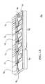
- FIG. 1Bshows a longitudinal cross section of a laser assembly 100 of FIG. 1 A.
- laser assembly 100waveguide 105 , amplifier gain section 110 , front resonator mirror 120 , laser gain section 130 , laser phase control section 140 , back mirror 150 and electrical contact 160 , epitaxial structure 170 , laser 180 , optical amplifier 190 , output facet 195 , p type semiconductor layer 125 , n-type semiconductor layer 115 , mirror sampling period 135 , offset quantum wells 145 and stop etch layer 155 are shown.
- waveguide 105is formed between p-type and n-type semiconductor layers 125 and 115 , respectively.
- Mirrors 120 and 150are formed by sample gratings etched in waveguide 105 with sampling period 135 , as is well-understood in the art.
- FIG. 1Billustrates the structure resulting from an offset quantum well technique for optically active and passive section formation.
- the optically active sectionshave multiple quantum well layers 145 grown in a region offset from waveguide 105 .
- the multiple quantum well layersare separated from the waveguide by a thin stop etch layer 155 . Removal of quantum wells, by etching for example, forms optically passive sections.
- FIGS. 2A-2Cillustrate cross-sectional structures over a portion of laser assembly 100 (see FIG. 1) resulting from different techniques for forming optically active and passive sections and their junctions.
- FIG. 2Aillustrates a cross-sectional structure over a portion of laser assembly 100 (see FIG. 1) resulting from a selected area regrowth technique.
- the selected area regrowth techniqueuses a dielectric mask to selectively control the growth rate and composition over different areas of the epitaxial structure.
- the material's bandgapcan be shifted in certain sections making the material in that section passive or non-absorbing at desired wavelengths.
- optically passive section 210optically active section 220 , bandgap-shifted quantum wells 230 , active section quantum wells 240 , and waveguide 105 (see FIGS. 1A-1B) are shown.
- different portions of waveguide 105are optically active or passive due to bandgap-shifting of the quantum wells within the waveguide.
- FIG. 2Billustrates a cross-sectional structure over a portion of laser assembly 100 (see FIG. 1) resulting from a selected area disordering technique for forming optically active and passive sections.
- the selected area disordering techniqueuses a dielectric cap or ion implantation to introduce vacancies which can be diffused through an active region to disorder the quantum wells by intermixing them. This disordering shifts quantum well bandgaps, creating optically passive waveguide sections.
- optically passive section 210optically active section 220 , disordered wells 250 , active section multiple quantum wells 260 , and waveguide 105 (see FIGS. 1A-1B) are shown.
- different portions of waveguide 105 , sections 210 and 220are optically active or passive due to the organization of the quantum wells within the waveguide material.
- FIG. 2Cillustrates a cross-sectional structure over a portion of laser assembly 100 (see FIG. 1) resulting from a butt joint regrowth technique for forming optically active and passive sections.
- the entire waveguideis etched away in optically passive sections and an optically passive waveguide is grown again. The newly grown portion of the waveguide is butted up against the active waveguide.
- optically passive section 210 , optically active section 220 , active, butt-joint interface 270 , passive waveguide section 275 , active waveguide section 285 and waveguide 105are shown.
- active waveguide section 285 and passive waveguide section 275are separated by a distinct large gradient butt-joint interface 270 as a result of the etch removal process.
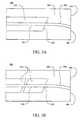
- FIGS. 3A-3Dare plan views, illustrating different embodiments of optical amplifier 190 (see FIG. 1 ).
- optical amplifier 190waveguide 105 , epitaxial structure 170 , output facet 195 , active amplifier section 310 , passive amplifier section 320 , active-passive junction 330 , curved waveguide portion 340 , flared waveguide portions 350 and 355 and waveguide mode adapter 360 are shown.
- optical amplifier 190has an active amplifier section 310 combined with a passive amplifier section 320 , where the passive amplifier section includes curved waveguide portion 340 .
- the curved waveguide portionintersects output facet 195 at an oblique angle. Both the waveguide curvature and oblique intersection significantly reduces the amount of light reflecting from the output facet back into the amplifier and laser.
- Active-passive junction 330is preferably oblique to a centerline of wave guide 105 so that any reflections from this interface coupling back into the amplifier and laser will be reduced. However, alternate embodiments may have active-passive junction 330 substantially normal to a centerline of the waveguide.
- FIG. 3Bshows an alternate embodiment where the amplifier active section has been segmented into a plurality of active sections in order to increase the amplifier output power and reduce a noise figure.
- the amplifier active sectionis segmented into two amplifier active sections 310 that may be independently controllable.
- Other embodimentshave more than two amplifier active sections. This segmenting of the amplifier enables the use of different bias points for the different sections. Having a plurality of amplifier stages allows higher saturated output powers to be reached with better noise performance.
- FIG. 3Cshows an alternate embodiment where a waveguide portion in the amplifier active section is flared, or tapered, to increase the saturated output power.
- Flared waveguide portion 350increases the amplifier active volume as compared to the embodiment shown in FIG. 3 A and decreases the photon density. To accomplish this effectively without introducing significant fiber coupling difficulties it is preferable to use an adiabatic flare, wherein there is no energy transfer across optical modes over the flare to a wider waveguide cross-section.
- a second flared-down section 355 to a narrow waveguide cross-sectionis positioned in the amplifier optically passive section 320 since it is difficult to couple effectively from a wide waveguide into a single mode fiber at output facet 195 .
- such a flared-down portionis before a curved waveguide portion 340 , otherwise, higher order modes will be excited when curving the wide waveguide.
- active-passive junction 330is angled so that any reflections from this interface coupling back into the amplifier and laser will be reduced.
- FIG. 3Dshows another embodiment including a waveguide mode adapter.
- a waveguide mode adapteris preferred in many embodiments to enlarge the optical mode near output facet 195 so that it is more closely matched to the mode in an optical fiber that, as an element in a communications system, may carry the light away from the output facet.
- Including a waveguide mode adapterthus reduces the fiber coupling loss and increases the alignment tolerances between laser assembly 100 (see FIG. 1) and an optical fiber of another system.
- An embodiment of a waveguide mode adapterincludes a section of passive waveguide wherein the waveguide's cross sectional is varied to expand the waveguide optical mode in an adiabatic manner.
Landscapes
- Physics & Mathematics (AREA)
- Electromagnetism (AREA)
- Optics & Photonics (AREA)
- Engineering & Computer Science (AREA)
- Chemical & Material Sciences (AREA)
- Condensed Matter Physics & Semiconductors (AREA)
- General Physics & Mathematics (AREA)
- Nanotechnology (AREA)
- Computer Networks & Wireless Communication (AREA)
- Biophysics (AREA)
- Life Sciences & Earth Sciences (AREA)
- Crystallography & Structural Chemistry (AREA)
- Signal Processing (AREA)
- Semiconductor Lasers (AREA)
Abstract
Description
Claims (26)
Priority Applications (18)
| Application Number | Priority Date | Filing Date | Title |
|---|---|---|---|
| US09/614,665US6687278B1 (en) | 1999-09-02 | 2000-07-12 | Method of generating an optical signal with a tunable laser source with integrated optical amplifier |
| US09/614,674US6624000B1 (en) | 1999-09-02 | 2000-07-12 | Method for making a monolithic wavelength converter assembly |
| US09/614,195US6574259B1 (en) | 1999-09-02 | 2000-07-12 | Method of making an opto-electronic laser with integrated modulator |
| US09/614,376US6614819B1 (en) | 1999-09-02 | 2000-07-12 | Method of modulating an optical wavelength with an opto-electronic laser with integrated modulator |
| US09/614,375US6658035B1 (en) | 1999-09-02 | 2000-07-12 | Tunable laser source with integrated optical amplifier |
| US09/614,378US6628690B1 (en) | 1999-09-02 | 2000-07-12 | Opto-electronic laser with integrated modulator |
| US09/614,895US6349106B1 (en) | 1999-09-02 | 2000-07-12 | Method for converting an optical wavelength using a monolithic wavelength converter assembly |
| US09/614,377US6580739B1 (en) | 1999-09-02 | 2000-07-12 | Integrated opto-electronic wavelength converter assembly |
| US09/614,224US6654400B1 (en) | 1999-09-02 | 2000-07-12 | Method of making a tunable laser source with integrated optical amplifier |
| PCT/US2001/017884WO2001095444A2 (en) | 2000-06-02 | 2001-06-01 | High-power sampled grating distributed bragg reflector lasers |
| CA2410964ACA2410964C (en) | 2000-06-02 | 2001-06-01 | High-power, manufacturable sampled grating distributed bragg reflector lasers |
| DE60105154TDE60105154T2 (en) | 2000-06-02 | 2001-06-01 | HIGH PERFORMANCE LASER WITH TEAMED GRID AND DISTRIBUTED BRAGG REFLECTOR |
| AU2001266663AAU2001266663A1 (en) | 2000-06-02 | 2001-06-01 | High-power, manufacturable sampled grating distributed bragg reflector lasers |
| AT01944233TATE274760T1 (en) | 2000-06-02 | 2001-06-01 | HIGH POWER LASER WITH SAMPLED GRID AND DISTRIBUTED BRAGG REFLECTOR |
| EP01944233AEP1290765B1 (en) | 2000-06-02 | 2001-06-01 | High-power sampled grating distributed bragg reflector lasers |
| US09/872,438US6909734B2 (en) | 1999-09-02 | 2001-06-01 | High-power, manufacturable sampled grating distributed Bragg reflector lasers |
| JP2002502873AJP5443660B2 (en) | 2000-06-02 | 2001-06-01 | High output, manufacturable extraction grating dispersed Bragg reflector laser |
| CN01810499.1ACN1227789C (en) | 2000-06-02 | 2001-06-01 | High Power Sampling Grating Distributed Bragg Reflection Laser |
Applications Claiming Priority (12)
| Application Number | Priority Date | Filing Date | Title |
|---|---|---|---|
| US15207299P | 1999-09-02 | 1999-09-02 | |
| US15204999P | 1999-09-02 | 1999-09-02 | |
| US15203899P | 1999-09-02 | 1999-09-02 | |
| US09/614,195US6574259B1 (en) | 1999-09-02 | 2000-07-12 | Method of making an opto-electronic laser with integrated modulator |
| US09/614,375US6658035B1 (en) | 1999-09-02 | 2000-07-12 | Tunable laser source with integrated optical amplifier |
| US09/614,378US6628690B1 (en) | 1999-09-02 | 2000-07-12 | Opto-electronic laser with integrated modulator |
| US09/614,895US6349106B1 (en) | 1999-09-02 | 2000-07-12 | Method for converting an optical wavelength using a monolithic wavelength converter assembly |
| US09/614,665US6687278B1 (en) | 1999-09-02 | 2000-07-12 | Method of generating an optical signal with a tunable laser source with integrated optical amplifier |
| US09/614,224US6654400B1 (en) | 1999-09-02 | 2000-07-12 | Method of making a tunable laser source with integrated optical amplifier |
| US09/614,674US6624000B1 (en) | 1999-09-02 | 2000-07-12 | Method for making a monolithic wavelength converter assembly |
| US09/614,377US6580739B1 (en) | 1999-09-02 | 2000-07-12 | Integrated opto-electronic wavelength converter assembly |
| US09/614,376US6614819B1 (en) | 1999-09-02 | 2000-07-12 | Method of modulating an optical wavelength with an opto-electronic laser with integrated modulator |
Related Parent Applications (6)
| Application Number | Title | Priority Date | Filing Date |
|---|---|---|---|
| US09/614,224Continuation-In-PartUS6654400B1 (en) | 1999-09-02 | 2000-07-12 | Method of making a tunable laser source with integrated optical amplifier |
| US09/614,377Continuation-In-PartUS6580739B1 (en) | 1999-09-02 | 2000-07-12 | Integrated opto-electronic wavelength converter assembly |
| US09/614,674Continuation-In-PartUS6624000B1 (en) | 1999-09-02 | 2000-07-12 | Method for making a monolithic wavelength converter assembly |
| US09/614,895Continuation-In-PartUS6349106B1 (en) | 1999-09-02 | 2000-07-12 | Method for converting an optical wavelength using a monolithic wavelength converter assembly |
| US09/614,378Continuation-In-PartUS6628690B1 (en) | 1999-09-02 | 2000-07-12 | Opto-electronic laser with integrated modulator |
| US61486500AContinuation-In-Part | 1999-09-02 | 2000-07-12 |
Related Child Applications (6)
| Application Number | Title | Priority Date | Filing Date |
|---|---|---|---|
| US09/614,375Continuation-In-PartUS6658035B1 (en) | 1999-09-02 | 2000-07-12 | Tunable laser source with integrated optical amplifier |
| US09/614,377Continuation-In-PartUS6580739B1 (en) | 1999-09-02 | 2000-07-12 | Integrated opto-electronic wavelength converter assembly |
| US09/614,895Continuation-In-PartUS6349106B1 (en) | 1999-09-02 | 2000-07-12 | Method for converting an optical wavelength using a monolithic wavelength converter assembly |
| US09/614,378Continuation-In-PartUS6628690B1 (en) | 1999-09-02 | 2000-07-12 | Opto-electronic laser with integrated modulator |
| US09/614,195Continuation-In-PartUS6574259B1 (en) | 1999-09-02 | 2000-07-12 | Method of making an opto-electronic laser with integrated modulator |
| US09/872,438Continuation-In-PartUS6909734B2 (en) | 1999-09-02 | 2001-06-01 | High-power, manufacturable sampled grating distributed Bragg reflector lasers |
Publications (1)
| Publication Number | Publication Date |
|---|---|
| US6687278B1true US6687278B1 (en) | 2004-02-03 |
Family
ID=30449777
Family Applications (2)
| Application Number | Title | Priority Date | Filing Date |
|---|---|---|---|
| US09/614,665Expired - LifetimeUS6687278B1 (en) | 1999-09-02 | 2000-07-12 | Method of generating an optical signal with a tunable laser source with integrated optical amplifier |
| US09/614,195Expired - LifetimeUS6574259B1 (en) | 1999-09-02 | 2000-07-12 | Method of making an opto-electronic laser with integrated modulator |
Family Applications After (1)
| Application Number | Title | Priority Date | Filing Date |
|---|---|---|---|
| US09/614,195Expired - LifetimeUS6574259B1 (en) | 1999-09-02 | 2000-07-12 | Method of making an opto-electronic laser with integrated modulator |
Country Status (1)
| Country | Link |
|---|---|
| US (2) | US6687278B1 (en) |
Cited By (42)
| Publication number | Priority date | Publication date | Assignee | Title |
|---|---|---|---|---|
| US20040008933A1 (en)* | 2002-07-09 | 2004-01-15 | Daniel Mahgerefteh | High-speed transmission system comprising a coupled multi-cavity optical discriminator |
| US20040190580A1 (en)* | 2003-03-04 | 2004-09-30 | Bardia Pezeshki | High-yield high-precision distributed feedback laser based on an array |
| US20050271392A1 (en)* | 2002-11-06 | 2005-12-08 | Yasuhiro Matsui | Reach extension by using external bragg grating for spectral filtering |
| US20060002718A1 (en)* | 2002-11-06 | 2006-01-05 | Yasuhiro Matsui | Chirp managed directly modulated laser with bandwidth limiting optical spectrum reshaper |
| US20060018666A1 (en)* | 2002-11-06 | 2006-01-26 | Yasuhiro Matsui | Adiabatically frequency modulated source |
| US20060039502A1 (en)* | 2002-11-06 | 2006-02-23 | Daniel Mahgerefteh | Phase correlated quadrature amplitude modulation |
| US20060078338A1 (en)* | 2002-11-06 | 2006-04-13 | Bart Johnson | Thermal chirp compensation systems for a chirp managed directly modulated laser (CML™) data Link |
| US20070110114A1 (en)* | 2003-04-30 | 2007-05-17 | Reithmaier Johann P | Multisectional laser |
| US20080002990A1 (en)* | 2002-11-06 | 2008-01-03 | Mccallion Kevin | Multi-ring resonator implementation of optical spectrum reshaper for chirp managed laser technology |
| US20080025731A1 (en)* | 2002-12-03 | 2008-01-31 | Daniel Mahgerefteh | Versatile compact transmitter for generation of advanced modulation formats |
| US20080158639A1 (en)* | 2006-10-24 | 2008-07-03 | Mccallion Kevin | Spectral response modification via spatial filtering with optical fiber |
| US20080159747A1 (en)* | 2006-12-28 | 2008-07-03 | Finisar Corporation | Integral Phase Rule for Reducing Dispersion Errors in an Adiabatically Chirped Amplitude Modulated Signal |
| US20080166130A1 (en)* | 2002-07-09 | 2008-07-10 | Daniel Mahgerefteh | Wavelength division multiplexing source using multifunctional filters |
| US20080166134A1 (en)* | 2006-12-22 | 2008-07-10 | Finisar Corporation | Optical Transmitter Having a Widely Tunable Directly Modulated Laser and Periodic Optical Spectrum Reshaping Element |
| US20080187325A1 (en)* | 2007-02-02 | 2008-08-07 | Mccallion Kevin J | Temperature stabilizing packaging for optoelectronic components in a transmitter module |
| US20080193132A1 (en)* | 2007-02-08 | 2008-08-14 | Finisar Corporation | Wdm pon based on dml |
| US20080240180A1 (en)* | 2002-12-03 | 2008-10-02 | Finisar Corporation | Optical fm source based on intra-cavity phase and amplitude modulation in lasers |
| US20080240733A1 (en)* | 2007-04-02 | 2008-10-02 | Finisar Corporation | Dispersion compensator for frequency reshaped optical signals |
| US20080247763A1 (en)* | 2007-04-06 | 2008-10-09 | Finisar Corporation | Chirped laser with passive filter element for differential phase shift keying generation |
| US20080291950A1 (en)* | 2003-02-25 | 2008-11-27 | Finisar Corporation | Optical beam steering for tunable laser applications |
| US20090003842A1 (en)* | 2007-04-06 | 2009-01-01 | Finisar Corporation | Chirped laser with passive filter element for differential phase shift keying generation |
| US20090016740A1 (en)* | 2002-12-03 | 2009-01-15 | Daniel Mahgerefteh | Method and apparatus for compensating for fiber nonlinearity in a transmission system |
| US20090022452A1 (en)* | 2001-10-09 | 2009-01-22 | Infinera Corporation | Monolithic transmitter photonic integrated circuit (txpic) with a transversely disposed output |
| US20090060526A1 (en)* | 2002-12-03 | 2009-03-05 | Finisar Corporation | Optical fm source based on intra-cavity phase and amplitude modulation in lasers |
| US20090074020A1 (en)* | 2007-05-14 | 2009-03-19 | Finisar Corporation | DBR laser with improved thermal tuning effciency |
| US20090080905A1 (en)* | 2002-12-03 | 2009-03-26 | Nils Anders Olsson | High power, low distortion directly modulated laser transmitter |
| US7573928B1 (en) | 2003-09-05 | 2009-08-11 | Santur Corporation | Semiconductor distributed feedback (DFB) laser array with integrated attenuator |
| US20090269069A1 (en)* | 2008-04-25 | 2009-10-29 | Finisar Corporation | Passive wave division multiplexed transmitter having a directly modulated laser array |
| US20100238962A1 (en)* | 2009-03-23 | 2010-09-23 | Electronics And Telecommunications Research Institute | External cavity laser light source |
| US20100254665A1 (en)* | 2009-04-02 | 2010-10-07 | Oki Semiconductor Co., Ltd. | Semiconductor optical communication module and manufacturing method thereof |
| JP2010239007A (en)* | 2009-03-31 | 2010-10-21 | Opnext Japan Inc | Semiconductor laser element |
| US20100329666A1 (en)* | 2009-06-30 | 2010-12-30 | Xueyan Zheng | Thermal chirp compensation in a chirp managed laser |
| US8027593B2 (en) | 2007-02-08 | 2011-09-27 | Finisar Corporation | Slow chirp compensation for enhanced signal bandwidth and transmission performances in directly modulated lasers |
| US8131157B2 (en) | 2007-01-22 | 2012-03-06 | Finisar Corporation | Method and apparatus for generating signals with increased dispersion tolerance using a directly modulated laser transmitter |
| US8160455B2 (en) | 2008-01-22 | 2012-04-17 | Finisar Corporation | Method and apparatus for generating signals with increased dispersion tolerance using a directly modulated laser transmitter |
| CN103257509A (en)* | 2013-04-12 | 2013-08-21 | 中国科学院半导体研究所 | Selective area epitaxial growth monolithic integration wavelength converter |
| US20140193154A1 (en)* | 2010-02-22 | 2014-07-10 | Vello Systems, Inc. | Subchannel security at the optical layer |
| US9312662B1 (en) | 2014-09-30 | 2016-04-12 | Lumentum Operations Llc | Tunable laser source |
| US9548878B2 (en) | 2008-03-12 | 2017-01-17 | Hypres, Inc. | Digital radio frequency transceiver system and method |
| US20210083458A1 (en)* | 2019-09-17 | 2021-03-18 | Open Water Internet Inc. | Semiconductor optical amplifier |
| US10972209B2 (en) | 2009-12-08 | 2021-04-06 | Snell Holdings, Llc | Subchannel photonic routing, switching and protection with simplified upgrades of WDM optical networks |
| US11567206B1 (en)* | 2019-05-17 | 2023-01-31 | Insight Lidar, Inc. | Chip-scale coherent lidar utilizing quantum dots |
Families Citing this family (24)
| Publication number | Priority date | Publication date | Assignee | Title |
|---|---|---|---|---|
| IL137732A (en)* | 2000-08-07 | 2006-12-31 | Crosslight Photonics Ltd | Characterization of multiple section semiconductor lasers |
| IL139618A0 (en) | 2000-11-12 | 2002-02-10 | Crosslight Photonics Ltd | Wavelenght tuning optimization of semiconductor lasers |
| US6822980B2 (en)* | 2001-07-25 | 2004-11-23 | Adc Telecommunications, Inc. | Tunable semiconductor laser with integrated wideband reflector |
| US7653093B2 (en)* | 2001-09-10 | 2010-01-26 | Imec | Widely tunable twin guide laser structure |
| DE10201124A1 (en)* | 2002-01-09 | 2003-07-24 | Infineon Technologies Ag | Opto-electronic component for raising data transmission rates has a quantum point structure for making a functional link between monolithically integrated components. |
| US7035305B2 (en)* | 2002-05-10 | 2006-04-25 | Bookham Technology, Plc | Monolithically integrated high power laser optical device |
| US20040076199A1 (en)* | 2002-08-22 | 2004-04-22 | Agility Communications, Inc. | Chirp control of integrated laser-modulators having multiple sections |
| US7050689B2 (en)* | 2002-11-26 | 2006-05-23 | Agility Communications, Inc. | Photonic device with segmented absorption design |
| US20050013337A1 (en)* | 2003-05-30 | 2005-01-20 | Thomas Jung | Semiconductor injection locked lasers and method |
| US7633988B2 (en)* | 2003-07-31 | 2009-12-15 | Jds Uniphase Corporation | Tunable laser source with monolithically integrated interferometric optical modulator |
| US7565084B1 (en)* | 2004-09-15 | 2009-07-21 | Wach Michael L | Robustly stabilizing laser systems |
| WO2009126351A2 (en)* | 2008-01-18 | 2009-10-15 | The Regents Of The University Of California | Hybrid silicon laser-quantum well intermixing wafer bonded integration platform for advanced photonic circuits with electroabsorption modulators |
| JP5597029B2 (en)* | 2010-05-27 | 2014-10-01 | 住友電気工業株式会社 | Tunable semiconductor laser |
| KR101394965B1 (en)* | 2010-10-14 | 2014-05-16 | 한국전자통신연구원 | Wavelength tunable external cavity laser generating device |
| US9268089B2 (en)* | 2011-04-21 | 2016-02-23 | Octrolix Bv | Layer having a non-linear taper and method of fabrication |
| US8470652B1 (en) | 2011-05-11 | 2013-06-25 | Hrl Laboratories, Llc | Monolithic integration of group III nitride enhancement layers |
| CN103248426A (en) | 2013-04-28 | 2013-08-14 | 华为技术有限公司 | Optical module and preparation method thereof |
| JP5773552B2 (en)* | 2013-09-20 | 2015-09-02 | 沖電気工業株式会社 | Optical element manufacturing method and optical element |
| JP6425631B2 (en)* | 2014-09-30 | 2018-11-21 | 三菱電機株式会社 | Semiconductor laser and optical integrated light source having the same |
| US10454239B2 (en) | 2015-08-28 | 2019-10-22 | International Business Machines Corporation | Wafer scale monolithic integration of lasers, modulators, and other optical components using ALD optical coatings |
| WO2017060836A1 (en)* | 2015-10-05 | 2017-04-13 | King Abdullah University Of Science And Technology | An apparatus comprising a waveguide-modulator and laser-diode and a method of manufacture thereof |
| US11070033B2 (en)* | 2018-02-23 | 2021-07-20 | Nokia Solutions & Networks Oy | Optical amplifier |
| JP7339563B2 (en)* | 2019-09-26 | 2023-09-06 | 日本電信電話株式会社 | optical transmitter |
| WO2021209115A1 (en)* | 2020-04-14 | 2021-10-21 | Huawei Technologies Co., Ltd. | Electroabsorption modulated laser |
Citations (20)
| Publication number | Priority date | Publication date | Assignee | Title |
|---|---|---|---|---|
| US4773074A (en)* | 1987-02-02 | 1988-09-20 | University Of Delaware | Dual mode laser/detector diode for optical fiber transmission lines |
| US4802182A (en)* | 1987-11-05 | 1989-01-31 | Xerox Corporation | Monolithic two dimensional waveguide coupled cavity laser/modulator |
| US4896325A (en)* | 1988-08-23 | 1990-01-23 | The Regents Of The University Of California | Multi-section tunable laser with differing multi-element mirrors |
| US5003550A (en)* | 1990-03-09 | 1991-03-26 | Spectra Diode Laboratories, Inc. | Integrated laser-amplifier with steerable beam |
| US5084894A (en)* | 1989-06-20 | 1992-01-28 | Optical Measurement Technology Development Co., Ltd. | Optical semiconductor device |
| US5088105A (en) | 1991-03-26 | 1992-02-11 | Spectra Diode Laboratories, Inc. | Optical amplifier with folded light path and laser-amplifier combination |
| EP0620475A1 (en) | 1993-03-15 | 1994-10-19 | Canon Kabushiki Kaisha | Optical devices and optical communication systems using the optical device |
| US5379318A (en)* | 1994-01-31 | 1995-01-03 | Telefonaktiebolaget L M Ericsson | Alternating grating tunable DBR laser |
| US5396511A (en)* | 1991-11-07 | 1995-03-07 | Hitachi, Ltd. | Semiconductor laser apparatus with curved waveguide |
| US5479539A (en) | 1994-06-15 | 1995-12-26 | Texas Instruments Incorporated | Integrated optical transmitter and receiver |
| US5525541A (en) | 1994-01-31 | 1996-06-11 | France Telecom | Method of making an electronic and/or photonic component |
| US5539571A (en)* | 1992-09-21 | 1996-07-23 | Sdl, Inc. | Differentially pumped optical amplifer and mopa device |
| US5625636A (en) | 1991-10-11 | 1997-04-29 | Bryan; Robert P. | Integration of photoactive and electroactive components with vertical cavity surface emitting lasers |
| US5674778A (en) | 1994-11-08 | 1997-10-07 | Samsung Electronics Co., Ltd. | Method of manufacturing an optoelectronic circuit including heterojunction bipolar transistor, laser and photodetector |
| US5715268A (en) | 1994-01-24 | 1998-02-03 | Sdl, Inc. | Laser amplifiers with suppressed self oscillation |
| US5742045A (en) | 1994-10-26 | 1998-04-21 | The United States Of America As Represented By The Secretary Of The Air Force | Apparatus using diode laser logic to form a configurable optical gate system |
| US5838714A (en)* | 1995-08-18 | 1998-11-17 | France Telecom | Tunable wavelength laser emission components |
| US5914480A (en)* | 1990-05-29 | 1999-06-22 | Symbol Technologies, Inc. | Scanning device formed from integrated components on a semiconductor substrate |
| US5936994A (en)* | 1997-09-18 | 1999-08-10 | Northern Telecom Limited | Two-section complex coupled distributed feedback semiconductor laser with enhanced wavelength tuning range |
| EP1539028A2 (en) | 2002-07-08 | 2005-06-15 | Ossur Engineering Inc. | Socket liner incorporating sensors to monitor amputee progress |
Family Cites Families (10)
| Publication number | Priority date | Publication date | Assignee | Title |
|---|---|---|---|---|
| US5145792A (en)* | 1988-05-23 | 1992-09-08 | Optical Measurement Technology Development Co., Ltd. | Method of fabricating a semiconductor optical device |
| DE69111197T2 (en)* | 1990-11-21 | 1995-11-16 | Toshiba Kawasaki Kk | Tunable semiconductor laser with distributed feedback. |
| US5325392A (en)* | 1992-03-06 | 1994-06-28 | Nippon Telegraph And Telephone Corporation | Distributed reflector and wavelength-tunable semiconductor laser |
| US5347526A (en)* | 1992-03-31 | 1994-09-13 | Kabushiki Kaisha Toshiba | Wavelength-tunable semiconductor laser |
| US5452118A (en)* | 1993-04-20 | 1995-09-19 | Spire Corporation | Optical heterodyne receiver for fiber optic communications system |
| FR2716303B1 (en)* | 1994-02-11 | 1996-04-05 | Franck Delorme | Wavelength tunable distributed Bragg reflector laser with selectively activated virtual diffraction gratings. |
| US5841799A (en)* | 1994-12-17 | 1998-11-24 | Canon Kabushiki Kaisha | Semiconductor laser, modulation method therefor and optical communication system using the same |
| JP2870632B2 (en)* | 1995-07-13 | 1999-03-17 | 日本電気株式会社 | Semiconductor optical integrated circuit and method of manufacturing the same |
| DE19652529A1 (en)* | 1996-12-17 | 1998-06-18 | Siemens Ag | Optoelectronic component with MQW structures |
| US6208454B1 (en)* | 1997-12-23 | 2001-03-27 | Agere Systems Optoelectronics Guardian Corp | All-optical mach-zehnder wavelength converter with monolithically integrated laser |
- 2000
- 2000-07-12USUS09/614,665patent/US6687278B1/ennot_activeExpired - Lifetime
- 2000-07-12USUS09/614,195patent/US6574259B1/ennot_activeExpired - Lifetime
Patent Citations (20)
| Publication number | Priority date | Publication date | Assignee | Title |
|---|---|---|---|---|
| US4773074A (en)* | 1987-02-02 | 1988-09-20 | University Of Delaware | Dual mode laser/detector diode for optical fiber transmission lines |
| US4802182A (en)* | 1987-11-05 | 1989-01-31 | Xerox Corporation | Monolithic two dimensional waveguide coupled cavity laser/modulator |
| US4896325A (en)* | 1988-08-23 | 1990-01-23 | The Regents Of The University Of California | Multi-section tunable laser with differing multi-element mirrors |
| US5084894A (en)* | 1989-06-20 | 1992-01-28 | Optical Measurement Technology Development Co., Ltd. | Optical semiconductor device |
| US5003550A (en)* | 1990-03-09 | 1991-03-26 | Spectra Diode Laboratories, Inc. | Integrated laser-amplifier with steerable beam |
| US5914480A (en)* | 1990-05-29 | 1999-06-22 | Symbol Technologies, Inc. | Scanning device formed from integrated components on a semiconductor substrate |
| US5088105A (en) | 1991-03-26 | 1992-02-11 | Spectra Diode Laboratories, Inc. | Optical amplifier with folded light path and laser-amplifier combination |
| US5625636A (en) | 1991-10-11 | 1997-04-29 | Bryan; Robert P. | Integration of photoactive and electroactive components with vertical cavity surface emitting lasers |
| US5396511A (en)* | 1991-11-07 | 1995-03-07 | Hitachi, Ltd. | Semiconductor laser apparatus with curved waveguide |
| US5539571A (en)* | 1992-09-21 | 1996-07-23 | Sdl, Inc. | Differentially pumped optical amplifer and mopa device |
| EP0620475A1 (en) | 1993-03-15 | 1994-10-19 | Canon Kabushiki Kaisha | Optical devices and optical communication systems using the optical device |
| US5715268A (en) | 1994-01-24 | 1998-02-03 | Sdl, Inc. | Laser amplifiers with suppressed self oscillation |
| US5525541A (en) | 1994-01-31 | 1996-06-11 | France Telecom | Method of making an electronic and/or photonic component |
| US5379318A (en)* | 1994-01-31 | 1995-01-03 | Telefonaktiebolaget L M Ericsson | Alternating grating tunable DBR laser |
| US5479539A (en) | 1994-06-15 | 1995-12-26 | Texas Instruments Incorporated | Integrated optical transmitter and receiver |
| US5742045A (en) | 1994-10-26 | 1998-04-21 | The United States Of America As Represented By The Secretary Of The Air Force | Apparatus using diode laser logic to form a configurable optical gate system |
| US5674778A (en) | 1994-11-08 | 1997-10-07 | Samsung Electronics Co., Ltd. | Method of manufacturing an optoelectronic circuit including heterojunction bipolar transistor, laser and photodetector |
| US5838714A (en)* | 1995-08-18 | 1998-11-17 | France Telecom | Tunable wavelength laser emission components |
| US5936994A (en)* | 1997-09-18 | 1999-08-10 | Northern Telecom Limited | Two-section complex coupled distributed feedback semiconductor laser with enhanced wavelength tuning range |
| EP1539028A2 (en) | 2002-07-08 | 2005-06-15 | Ossur Engineering Inc. | Socket liner incorporating sensors to monitor amputee progress |
Non-Patent Citations (5)
| Title |
|---|
| Bar-Chaim, N. et al., "Monolithic Optoelectronic Integration of a GaAIAs Laser, a Field-Effect Transistor, and a Photodiode", Applied Physics Letters, US, American Institute of Physics, May 15, 1984, vol. 44, No. 10, pp. 941-943. |
| Byoung-Sung, K. et al., "Dynamic Analysis of Widely Tunable Laser Diodes Integrated with Sampled-and-Chirped-Grating Distributed Bragg Reflectors and an Electroabsorption Modulator", IEICE Trans Electron, Aug. 1998, vol. E81-C, No. 8, pp. 1342-1349. |
| Jayaraman, V. et al., "Theory, Design, and Performance of Extended Tuning Range Semiconductor Lasers with Sampled Gratings", IEEE Journal of Quantum Electronics, Jun. 29, 1993, vol. 29, No. 6, pp. 1824-1834. |
| Koch, T.L., "Semiconductor Photonic Integrated Cicruits", IEEE Journal of Quantum Electronics, Mar. 27, 1991, No. 3, pp. 641-653. |
| San-Liang, L. et al., "Sampled Grating DBR Laser Arrays with Adjustable 0.8/1.6-nm Wavelength Spacing", IEEE Photonics Technology Letters, Aug. 1999, vol. 11, No. 8, pp. 955-957. |
Cited By (78)
| Publication number | Priority date | Publication date | Assignee | Title |
|---|---|---|---|---|
| US20090022452A1 (en)* | 2001-10-09 | 2009-01-22 | Infinera Corporation | Monolithic transmitter photonic integrated circuit (txpic) with a transversely disposed output |
| US7773837B2 (en)* | 2001-10-09 | 2010-08-10 | Infinera Corporation | Monolithic transmitter photonic integrated circuit (TXPIC) with a transversely disposed output |
| US20080166130A1 (en)* | 2002-07-09 | 2008-07-10 | Daniel Mahgerefteh | Wavelength division multiplexing source using multifunctional filters |
| US20040008933A1 (en)* | 2002-07-09 | 2004-01-15 | Daniel Mahgerefteh | High-speed transmission system comprising a coupled multi-cavity optical discriminator |
| US20080247765A1 (en)* | 2002-07-09 | 2008-10-09 | Finisar Corporation | Power source for a dispersion compensation fiber optic system |
| US7616902B2 (en) | 2002-07-09 | 2009-11-10 | Finisar Corporation | Power source for a dispersion compensation fiber optic system |
| US7657179B2 (en) | 2002-07-09 | 2010-02-02 | Finisar Corporation | Wavelength division multiplexing source using multifunctional filters |
| US7663762B2 (en) | 2002-07-09 | 2010-02-16 | Finisar Corporation | High-speed transmission system comprising a coupled multi-cavity optical discriminator |
| US7564889B2 (en) | 2002-11-06 | 2009-07-21 | Finisar Corporation | Adiabatically frequency modulated source |
| US20060002718A1 (en)* | 2002-11-06 | 2006-01-05 | Yasuhiro Matsui | Chirp managed directly modulated laser with bandwidth limiting optical spectrum reshaper |
| US7558488B2 (en)* | 2002-11-06 | 2009-07-07 | Finisar Corporation | Reach extension by using external Bragg grating for spectral filtering |
| US7505694B2 (en) | 2002-11-06 | 2009-03-17 | Finisar Corporation | Thermal chirp compensation systems for a chirp managed directly modulated laser (CML™) data link |
| US20080002990A1 (en)* | 2002-11-06 | 2008-01-03 | Mccallion Kevin | Multi-ring resonator implementation of optical spectrum reshaper for chirp managed laser technology |
| US7502532B2 (en) | 2002-11-06 | 2009-03-10 | Finisar Corporation | Multi-ring resonator implementation of optical spectrum reshaper for chirp managed laser technology |
| US7742542B2 (en) | 2002-11-06 | 2010-06-22 | Finisar Corporation | Phase correlated quadrature amplitude modulation |
| US20060078338A1 (en)* | 2002-11-06 | 2006-04-13 | Bart Johnson | Thermal chirp compensation systems for a chirp managed directly modulated laser (CML™) data Link |
| US7536113B2 (en) | 2002-11-06 | 2009-05-19 | Finisar Corporation | Chirp managed directly modulated laser with bandwidth limiting optical spectrum reshaper |
| US20060039502A1 (en)* | 2002-11-06 | 2006-02-23 | Daniel Mahgerefteh | Phase correlated quadrature amplitude modulation |
| US20060018666A1 (en)* | 2002-11-06 | 2006-01-26 | Yasuhiro Matsui | Adiabatically frequency modulated source |
| US20050271392A1 (en)* | 2002-11-06 | 2005-12-08 | Yasuhiro Matsui | Reach extension by using external bragg grating for spectral filtering |
| US20080025731A1 (en)* | 2002-12-03 | 2008-01-31 | Daniel Mahgerefteh | Versatile compact transmitter for generation of advanced modulation formats |
| US20080240180A1 (en)* | 2002-12-03 | 2008-10-02 | Finisar Corporation | Optical fm source based on intra-cavity phase and amplitude modulation in lasers |
| US7474859B2 (en) | 2002-12-03 | 2009-01-06 | Finisar Corporation | Versatile compact transmitter for generation of advanced modulation formats |
| US20090016740A1 (en)* | 2002-12-03 | 2009-01-15 | Daniel Mahgerefteh | Method and apparatus for compensating for fiber nonlinearity in a transmission system |
| US7925172B2 (en) | 2002-12-03 | 2011-04-12 | Finisar Corporation | High power, low distortion directly modulated laser transmitter |
| US20090060526A1 (en)* | 2002-12-03 | 2009-03-05 | Finisar Corporation | Optical fm source based on intra-cavity phase and amplitude modulation in lasers |
| US7907648B2 (en) | 2002-12-03 | 2011-03-15 | Finisar Corporation | Optical FM source based on intra-cavity phase and amplitude modulation in lasers |
| US7813648B2 (en) | 2002-12-03 | 2010-10-12 | Finisar Corporation | Method and apparatus for compensating for fiber nonlinearity in a transmission system |
| US7860404B2 (en) | 2002-12-03 | 2010-12-28 | Finisar Corporation | Optical FM source based on intra-cavity phase and amplitude modulation in lasers |
| US20090080905A1 (en)* | 2002-12-03 | 2009-03-26 | Nils Anders Olsson | High power, low distortion directly modulated laser transmitter |
| US20080291950A1 (en)* | 2003-02-25 | 2008-11-27 | Finisar Corporation | Optical beam steering for tunable laser applications |
| US8792531B2 (en) | 2003-02-25 | 2014-07-29 | Finisar Corporation | Optical beam steering for tunable laser applications |
| US20040190580A1 (en)* | 2003-03-04 | 2004-09-30 | Bardia Pezeshki | High-yield high-precision distributed feedback laser based on an array |
| US7957437B2 (en) | 2003-04-30 | 2011-06-07 | Nanoplus Nanosystems And Technologies Gmbh | Multisectional laser |
| US7570681B2 (en)* | 2003-04-30 | 2009-08-04 | Nanoplus Nanosystems And Technologies Gmbh | Multisectional laser |
| US20070110114A1 (en)* | 2003-04-30 | 2007-05-17 | Reithmaier Johann P | Multisectional laser |
| US20090268764A1 (en)* | 2003-04-30 | 2009-10-29 | Nanoplus Gmbh | Multisectional laser |
| US7573928B1 (en) | 2003-09-05 | 2009-08-11 | Santur Corporation | Semiconductor distributed feedback (DFB) laser array with integrated attenuator |
| US7697186B2 (en) | 2006-10-24 | 2010-04-13 | Finisar Corporation | Spectral response modification via spatial filtering with optical fiber |
| US20080158639A1 (en)* | 2006-10-24 | 2008-07-03 | Mccallion Kevin | Spectral response modification via spatial filtering with optical fiber |
| US7962045B2 (en) | 2006-12-22 | 2011-06-14 | Finisar Corporation | Optical transmitter having a widely tunable directly modulated laser and periodic optical spectrum reshaping element |
| US20080166134A1 (en)* | 2006-12-22 | 2008-07-10 | Finisar Corporation | Optical Transmitter Having a Widely Tunable Directly Modulated Laser and Periodic Optical Spectrum Reshaping Element |
| US7941057B2 (en) | 2006-12-28 | 2011-05-10 | Finisar Corporation | Integral phase rule for reducing dispersion errors in an adiabatically chirped amplitude modulated signal |
| US20080159747A1 (en)* | 2006-12-28 | 2008-07-03 | Finisar Corporation | Integral Phase Rule for Reducing Dispersion Errors in an Adiabatically Chirped Amplitude Modulated Signal |
| US8131157B2 (en) | 2007-01-22 | 2012-03-06 | Finisar Corporation | Method and apparatus for generating signals with increased dispersion tolerance using a directly modulated laser transmitter |
| US20080187325A1 (en)* | 2007-02-02 | 2008-08-07 | Mccallion Kevin J | Temperature stabilizing packaging for optoelectronic components in a transmitter module |
| US7962044B2 (en) | 2007-02-02 | 2011-06-14 | Finisar Corporation | Temperature stabilizing packaging for optoelectronic components in a transmitter module |
| US7991291B2 (en) | 2007-02-08 | 2011-08-02 | Finisar Corporation | WDM PON based on DML |
| US8027593B2 (en) | 2007-02-08 | 2011-09-27 | Finisar Corporation | Slow chirp compensation for enhanced signal bandwidth and transmission performances in directly modulated lasers |
| US20080193132A1 (en)* | 2007-02-08 | 2008-08-14 | Finisar Corporation | Wdm pon based on dml |
| US7697847B2 (en) | 2007-04-02 | 2010-04-13 | Finisar Corporation | Dispersion compensator for frequency reshaped optical signals |
| US20080240733A1 (en)* | 2007-04-02 | 2008-10-02 | Finisar Corporation | Dispersion compensator for frequency reshaped optical signals |
| US20090003842A1 (en)* | 2007-04-06 | 2009-01-01 | Finisar Corporation | Chirped laser with passive filter element for differential phase shift keying generation |
| US8204386B2 (en) | 2007-04-06 | 2012-06-19 | Finisar Corporation | Chirped laser with passive filter element for differential phase shift keying generation |
| US20080247763A1 (en)* | 2007-04-06 | 2008-10-09 | Finisar Corporation | Chirped laser with passive filter element for differential phase shift keying generation |
| US7991297B2 (en) | 2007-04-06 | 2011-08-02 | Finisar Corporation | Chirped laser with passive filter element for differential phase shift keying generation |
| US7778295B2 (en) | 2007-05-14 | 2010-08-17 | Finisar Corporation | DBR laser with improved thermal tuning efficiency |
| US20090074020A1 (en)* | 2007-05-14 | 2009-03-19 | Finisar Corporation | DBR laser with improved thermal tuning effciency |
| US8160455B2 (en) | 2008-01-22 | 2012-04-17 | Finisar Corporation | Method and apparatus for generating signals with increased dispersion tolerance using a directly modulated laser transmitter |
| US9548878B2 (en) | 2008-03-12 | 2017-01-17 | Hypres, Inc. | Digital radio frequency transceiver system and method |
| US10382132B2 (en) | 2008-03-12 | 2019-08-13 | Hypres, Inc. | Digital radio frequency transceiver system and method |
| US20090269069A1 (en)* | 2008-04-25 | 2009-10-29 | Finisar Corporation | Passive wave division multiplexed transmitter having a directly modulated laser array |
| US8260150B2 (en) | 2008-04-25 | 2012-09-04 | Finisar Corporation | Passive wave division multiplexed transmitter having a directly modulated laser array |
| US20100238962A1 (en)* | 2009-03-23 | 2010-09-23 | Electronics And Telecommunications Research Institute | External cavity laser light source |
| US8107508B2 (en)* | 2009-03-23 | 2012-01-31 | Electronics And Telecommunications Research Institute | External cavity laser light source |
| JP2010239007A (en)* | 2009-03-31 | 2010-10-21 | Opnext Japan Inc | Semiconductor laser element |
| US20100254665A1 (en)* | 2009-04-02 | 2010-10-07 | Oki Semiconductor Co., Ltd. | Semiconductor optical communication module and manufacturing method thereof |
| US8277131B2 (en)* | 2009-04-02 | 2012-10-02 | Lapis Semiconductor Co., Ltd. | Semiconductor optical communication module and manufacturing method thereof |
| US20100329666A1 (en)* | 2009-06-30 | 2010-12-30 | Xueyan Zheng | Thermal chirp compensation in a chirp managed laser |
| US8199785B2 (en) | 2009-06-30 | 2012-06-12 | Finisar Corporation | Thermal chirp compensation in a chirp managed laser |
| US10972209B2 (en) | 2009-12-08 | 2021-04-06 | Snell Holdings, Llc | Subchannel photonic routing, switching and protection with simplified upgrades of WDM optical networks |
| US20140193154A1 (en)* | 2010-02-22 | 2014-07-10 | Vello Systems, Inc. | Subchannel security at the optical layer |
| CN103257509A (en)* | 2013-04-12 | 2013-08-21 | 中国科学院半导体研究所 | Selective area epitaxial growth monolithic integration wavelength converter |
| CN103257509B (en)* | 2013-04-12 | 2016-08-03 | 中国科学院半导体研究所 | The single chip integrated Wavelength conversion devices of selective area epitaxial |
| US9728933B2 (en) | 2014-09-30 | 2017-08-08 | Lumentum Operations Llc | Tunable laser source |
| US9312662B1 (en) | 2014-09-30 | 2016-04-12 | Lumentum Operations Llc | Tunable laser source |
| US11567206B1 (en)* | 2019-05-17 | 2023-01-31 | Insight Lidar, Inc. | Chip-scale coherent lidar utilizing quantum dots |
| US20210083458A1 (en)* | 2019-09-17 | 2021-03-18 | Open Water Internet Inc. | Semiconductor optical amplifier |
Also Published As
| Publication number | Publication date |
|---|---|
| US6574259B1 (en) | 2003-06-03 |
Similar Documents
| Publication | Publication Date | Title |
|---|---|---|
| US6687278B1 (en) | Method of generating an optical signal with a tunable laser source with integrated optical amplifier | |
| EP1210753B1 (en) | Tunable laser source with integrated optical amplifier | |
| WO2001017076A9 (en) | Tunable laser source with integrated optical amplifier | |
| US6580850B1 (en) | Optical waveguide multimode to single mode transformer | |
| US8467122B2 (en) | Hybrid laser source with ring-resonator reflector | |
| US7920322B2 (en) | Reflective semiconductor optical amplifier (R-SOA) with dual buried heterostructure | |
| US6597497B2 (en) | Semiconductor optical amplifier with transverse laser cavity intersecting optical signal path and method of fabrication thereof | |
| US6411764B1 (en) | Double core spot size converter using selective area growth and fabricating method thereof | |
| US20130016744A1 (en) | Laser source with tunable-grating-waveguide reflections | |
| US6363188B1 (en) | Mode expander with co-directional grating | |
| US5349602A (en) | Broad-area MOPA device with leaky waveguide beam expander | |
| US20120189025A1 (en) | Monolithic laser source using ring-resonator reflectors | |
| US20040258360A1 (en) | External gain element with mode converter and high index contrast waveguide | |
| US6614819B1 (en) | Method of modulating an optical wavelength with an opto-electronic laser with integrated modulator | |
| US7376167B2 (en) | Tunable ring laser with external grating operation in a single mode | |
| US6163631A (en) | Waveguide type optical integrated circuit element and method for fabricating same | |
| US5475777A (en) | Optical device with a pig tail optical fiber and its production method | |
| US6658035B1 (en) | Tunable laser source with integrated optical amplifier | |
| US7190852B2 (en) | Semiconductor devices with curved waveguides and mode transformers | |
| AU775671B2 (en) | Integrated wavelength tunable single and two-stage all-optical wavelength converter | |
| JPH11511911A (en) | Opto-semiconductor component with deep ridge waveguide | |
| US6654400B1 (en) | Method of making a tunable laser source with integrated optical amplifier | |
| US6970654B1 (en) | Optical signal generator | |
| JP3382471B2 (en) | Semiconductor optical device and optical network using the same | |
| US20050243882A1 (en) | Dual-wavelength semiconductor laser |
Legal Events
| Date | Code | Title | Description |
|---|---|---|---|
| AS | Assignment | Owner name:AGILITY COMMUNICATIONS, INC., CALIFORNIA Free format text:ASSIGNMENT OF ASSIGNORS INTEREST;ASSIGNORS:BECK, THOMAS MASON;FISH, GREGORY;COLDREN, LARRY;REEL/FRAME:011254/0930;SIGNING DATES FROM 20000822 TO 20000824 | |
| AS | Assignment | Owner name:AGILITY COMMUNICATIONS, INC., CALIFORNIA Free format text:CHANGE OF ADDRESS;ASSIGNOR:AGILITY COMMUNICATIONS, INC.;REEL/FRAME:013131/0904 Effective date:20020624 | |
| STCF | Information on status: patent grant | Free format text:PATENTED CASE | |
| FEPP | Fee payment procedure | Free format text:PAT HOLDER NO LONGER CLAIMS SMALL ENTITY STATUS, ENTITY STATUS SET TO UNDISCOUNTED (ORIGINAL EVENT CODE: STOL); ENTITY STATUS OF PATENT OWNER: LARGE ENTITY | |
| FPAY | Fee payment | Year of fee payment:4 | |
| AS | Assignment | Owner name:JDS UNIPHASE CORPORATION, CALIFORNIA Free format text:ASSIGNMENT OF ASSIGNORS INTEREST;ASSIGNOR:AGILITY COMMUNICATIONS, INC.;REEL/FRAME:021266/0423 Effective date:20080717 | |
| AS | Assignment | Owner name:JDS UNIPHASE CORPORATION, CALIFORNIA Free format text:CHANGE OF ASSIGNEE ADDRESS;ASSIGNOR:JDS UNIPHASE CORPORATION;REEL/FRAME:021380/0671 Effective date:20080813 | |
| RR | Request for reexamination filed | Effective date:20081016 | |
| FPAY | Fee payment | Year of fee payment:8 | |
| B1 | Reexamination certificate first reexamination | Free format text:CLAIMS 1-26 ARE CANCELLED. NEW CLAIMS 27-58 ARE ADDED AND DETERMINED TO BE PATENTABLE. | |
| FPAY | Fee payment | Year of fee payment:12 | |
| AS | Assignment | Owner name:LUMENTUM OPERATIONS LLC, CALIFORNIA Free format text:ASSIGNMENT OF ASSIGNORS INTEREST;ASSIGNOR:JDS UNIPHASE CORPORATION;REEL/FRAME:036420/0340 Effective date:20150731 | |
| FEPP | Fee payment procedure | Free format text:PAYOR NUMBER ASSIGNED (ORIGINAL EVENT CODE: ASPN); ENTITY STATUS OF PATENT OWNER: LARGE ENTITY | |
| AS | Assignment | Owner name:LUMENTUM OPERATIONS LLC, CALIFORNIA Free format text:CORRECTIVE ASSIGNMENT TO CORRECT THE PATENTS LISTED ON PAGE A-A33 PREVIOUSLY RECORDED ON REEL 036420 FRAME 0340. ASSIGNOR(S) HEREBY CONFIRMS THE PATENT NUMBERS 7,868,247 AND 6,476,312 WERE LISTED IN ERROR AND SHOULD BE REMOVED;ASSIGNOR:JDS UNIPHASE CORPORATION;REEL/FRAME:037562/0513 Effective date:20150731 Owner name:LUMENTUM OPERATIONS LLC, CALIFORNIA Free format text:CORRECTIVE ASSIGNMENT TO CORRECT INCORRECT PATENTS 7,868,247 AND 6,476,312 ON PAGE A-A33 PREVIOUSLY RECORDED ON REEL 036420 FRAME 0340. ASSIGNOR(S) HEREBY CONFIRMS THE ASSIGNMENT;ASSIGNOR:JDS UNIPHASE CORPORATION;REEL/FRAME:037562/0513 Effective date:20150731 | |
| AS | Assignment | Owner name:LUMENTUM OPERATIONS LLC, CALIFORNIA Free format text:CORRECTIVE ASSIGNMENT TO CORRECT THE PATENTS LISTED ON PAGE A-A33 PATENT NUMBERS 7,868,247 AND 6,476,312 WERE LISTED IN ERROR AND SHOULD BE REMOVED. PREVIOUSLY RECORDED ON REEL 036420 FRAME 0340. ASSIGNOR(S) HEREBY CONFIRMS THE ASSIGNMENT;ASSIGNOR:JDS UNIPHASE CORPORATION;REEL/FRAME:037627/0641 Effective date:20150731 Owner name:LUMENTUM OPERATIONS LLC, CALIFORNIA Free format text:CORRECTIVE ASSIGNMENT TO CORRECT PATENTS 7,868,247 AND 6,476,312 LISTED ON PAGE A-A33 PREVIOUSLY RECORDED ON REEL 036420 FRAME 0340. ASSIGNOR(S) HEREBY CONFIRMS THE ASSIGNMENT;ASSIGNOR:JDS UNIPHASE CORPORATION;REEL/FRAME:037627/0641 Effective date:20150731 | |
| FEPP | Fee payment procedure | Free format text:PAYER NUMBER DE-ASSIGNED (ORIGINAL EVENT CODE: RMPN); ENTITY STATUS OF PATENT OWNER: LARGE ENTITY Free format text:PAYOR NUMBER ASSIGNED (ORIGINAL EVENT CODE: ASPN); ENTITY STATUS OF PATENT OWNER: LARGE ENTITY | |
| AS | Assignment | Owner name:DEUTSCHE BANK AG NEW YORK BRANCH, AS COLLATERAL AGENT, NEW YORK Free format text:PATENT SECURITY AGREEMENT;ASSIGNORS:LUMENTUM OPERATIONS LLC;OCLARO FIBER OPTICS, INC.;OCLARO, INC.;REEL/FRAME:047788/0511 Effective date:20181210 Owner name:DEUTSCHE BANK AG NEW YORK BRANCH, AS COLLATERAL AG Free format text:PATENT SECURITY AGREEMENT;ASSIGNORS:LUMENTUM OPERATIONS LLC;OCLARO FIBER OPTICS, INC.;OCLARO, INC.;REEL/FRAME:047788/0511 Effective date:20181210 | |
| AS | Assignment | Owner name:LUMENTUM OPERATIONS LLC, CALIFORNIA Free format text:RELEASE BY SECURED PARTY;ASSIGNOR:DEUTSCHE AG NEW YORK BRANCH;REEL/FRAME:051287/0556 Effective date:20191212 Owner name:OCLARO FIBER OPTICS, INC., CALIFORNIA Free format text:RELEASE BY SECURED PARTY;ASSIGNOR:DEUTSCHE AG NEW YORK BRANCH;REEL/FRAME:051287/0556 Effective date:20191212 Owner name:OCLARO, INC., CALIFORNIA Free format text:RELEASE BY SECURED PARTY;ASSIGNOR:DEUTSCHE AG NEW YORK BRANCH;REEL/FRAME:051287/0556 Effective date:20191212 |