US6686851B1 - Altitude tape and integral vertical speed indicator - Google Patents
Altitude tape and integral vertical speed indicatorDownload PDFInfo
- Publication number
- US6686851B1 US6686851B1US09/648,829US64882900AUS6686851B1US 6686851 B1US6686851 B1US 6686851B1US 64882900 AUS64882900 AUS 64882900AUS 6686851 B1US6686851 B1US 6686851B1
- Authority
- US
- United States
- Prior art keywords
- altitude
- display
- indicator
- levels
- scrolling
- Prior art date
- Legal status (The legal status is an assumption and is not a legal conclusion. Google has not performed a legal analysis and makes no representation as to the accuracy of the status listed.)
- Expired - Lifetime, expires
Links
Images


Classifications
- G—PHYSICS
- G01—MEASURING; TESTING
- G01C—MEASURING DISTANCES, LEVELS OR BEARINGS; SURVEYING; NAVIGATION; GYROSCOPIC INSTRUMENTS; PHOTOGRAMMETRY OR VIDEOGRAMMETRY
- G01C23/00—Combined instruments indicating more than one navigational value, e.g. for aircraft; Combined measuring devices for measuring two or more variables of movement, e.g. distance, speed or acceleration
- G01C23/005—Flight directors
Definitions
- the present inventionrelates to avionics, and more particularly, to altitude indicators on an avionics display.
- the cockpit of an airplanehas traditionally included a vast array of analog switches and rotary dials to monitor and control the dozens of functions and inputs necessary to safely fly an aircraft. It has long been a goal to simplify avionics controls so that important information is readily available to a pilot.
- Computer-controlled avionics display systemshave enjoyed widespread acceptance because of their ability to display a large number of parameters in just a few programmable displays, with menus and control bars enabling multiple display formats to be selectively displayed thereon as needed. Information that was once displayed on the rotary dials is now converted to digital form.
- a digital numeric readout of a parametermay not give as much information to a pilot as an analog rotary dial.
- an advantage of rotary dialsis that the position and the relative movement of the dial may deliver information over and above the explicit parameter displayed by the dial.
- the explicit parameter displayed by a rotary-dial altimeteris the altitude of an aircraft.
- the speed of the movement of the dialgives the pilot a feel for the rate of climb or descent.
- many altimetersare designed so that the dial is at a 12 o'clock position (straight up) when the aircraft is at an altitude that is an integer multiple of 1000 feet (i.e., 1000, 2000, 3000, etc.) and at a 6 o'clock position (straight down) when the aircraft is at an altitude that is an odd integer multiple of 500 feet (i.e., 500, 1500, 2500, etc.).
- These altitudesare known as cardinal altitudes and are frequently used in flight plans. A pilot can merely glance at the position of the dial to know the aircraft's vertical position in relation to nearby cardinal altitudes.
- This supplemental altitude informationmay not be as easy to ascertain when reading a purely numeric altitude reading. Furthermore, because so many parameters must be displayed on just a few computer-controlled displays, display space is at a premium. There simply may not be enough room to display the supplemental altitude information.
- a feature of the inventionis the combination of numeric and graphic display components to enhance altitude awareness of a pilot.
- An advantage of the inventionis that the supplemental altitude information may be displayed with the altitude of the aircraft.
- the inventionprovides a device for enhancing altitude awareness in an avionics display.
- the deviceincludes an altitude indicator that displays a current altitude on the avionics display.
- a scrolling display of altitude levelsis displayed with the altitude indicator on the avionics display.
- the scrolling displayincludes a plurality of scaled numbers that represent predetermined intervals of altitude levels surrounding the current altitude.
- the scrolling displayalso includes a non-numeric graphic construct that is displayed adjacent the plurality of scaled numbers.
- the graphic constructhas first and second substantially mirror-image portions that are positioned on first and second opposing sides of the plurality of scaled numbers.
- a controllercauses the altitude indicator to display the current altitude on the avionics display.
- the controlleralso causes the scrolling display to display the predetermined intervals of altitude levels surrounding the current altitude and to vary the graphic construct consistent with the predetermined altitude levels that are displayed.
- the inventionalso provides a device for enhancing altitude awareness in an avionics display.
- the deviceincludes an altitude indicator that displays a current altitude on the avionics display.
- a scrolling, scaled altitude tapeis displayed with the altitude indicator on the avionics display.
- the altitude tapeincludes a plurality of scaled numbers that represent predetermined intervals of altitude levels adjacent the current altitude.
- a vertical speed indicatoris superimposed on the altitude tape.
- the vertical speed indicatoris configured to display vertical speed.
- a controllercauses the altitude indicator to display the current altitude on the avionics display and further causes the scrolling display to display the predetermined levels of altitude levels.
- the controlleralso causes the vertical speed indicator to display vertical speed.
- the inventionfurther provides a method of enhancing altitude awareness in an avionics display.
- a current altitudeis indicated on the avionics display.
- a scrolling display of scaled numbersis displayed.
- the numbersrepresent predetermined intervals of altitude levels that are adjacent the current altitude.
- a substantially continuous non-numeric graphic constructis displayed beside the scrolling display of scaled numbers. The graphic construct is varied to highlight the predetermined intervals of altitude levels.
- FIG. 1is a block diagram of an avionics display system.
- FIG. 2is a view of a display format according to the invention.
- FIG. 3is a detail view of an altitude display area according to an embodiment of the invention.
- FIG. 4is a detail view of the altitude display area of FIG. 3 at another altitude level.
- FIG. 5is a detail view of an altitude display area according to yet another embodiment of the invention.
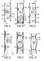
- FIG. 6is a detail view of an altitude display area according to still another embodiment of the invention.
- FIG. 7is a detail view of an altitude display area according to yet another embodiment of the invention.
- FIG. 8is a detail view of an altitude display area according to yet another embodiment of the invention.
- FIG. 9is a detail view of an altitude display area according to still another embodiment of the invention.
- FIG. 10is a detail view of an altitude display area according to still another embodiment of the invention.
- FIG. 11is a view of a display area according to another embodiment of the invention.
- An avionics display system 10is shown in block diagram form in FIG. 1 .
- Avionics display systemsare used to control other avionics systems and to display information received from other avionics systems. These other avionics systems (not shown) may include flight control systems, air data computers, engine indication systems, altimeters, traffic collision and avoidance systems, and other types of systems currently installed or planned for future aircraft applications.
- Avionics display system 10is preferably a primary flight display, which displays critical flight information such as airspeed, altitude, attitude, and bearing to a pilot.
- Avionics display systemstypically include a line-replaceable unit (LRU) 12 that may be mounted on the instrument panel of an aircraft. LRU 12 includes a controller 14 , which may be a known type of flight computer.
- LRUline-replaceable unit
- Controller 14typically has a processor 14 a , a memory 14 b , and an interface 14 c for communicating with other components in the LRU and the avionics display system.
- LRU 12also includes a display 16 that may be based on technologies such as cathode-ray tubes, liquid-crystal displays, organic light-emitting diodes, or other technologies.
- LRU 12may also include a keyboard 18 to input information into processor 14 .
- FIG. 2shows a display format 20 of display 16 according to the invention.
- display format 20includes a horizontal situation indicator (HSI) 22 coupled with a heading indicator 24 .
- HSI 22horizontal situation indicator 22
- ADIattitude director indicator
- To the left of ADI 26is an airspeed indicator 28
- To the right of ADI 26is an altitude display area 30 in which altitude is displayed.
- the relative positions of HSI 22 , heading indicator 24 , ADI 26 , airspeed indicator 28 and altitude display area 30are determined according to accepted avionics display formats.
- FIG. 3shows altitude display area 30 according to the invention.
- Altitude display area 30has a length 30 a and a width 30 b .
- An altitude indicator 32is located substantially midway along length 30 a of the altitude display area.
- Altitude indicator 32is stationary, that is, the altitude indicator does not move within altitude display area 30 as the altitude changes.
- altitude indicator 32includes a plurality of changeable digits 34 that combine to numerically display the current altitude of the aircraft.
- a scrolling display 40is also positioned within display area 30 .
- Scrolling display 40enhances the pilot's awareness of altitude by providing numeric and non-numeric representations of altitude levels that are adjacent the aircraft's current altitude.
- Scrolling display 40may be considered to be an altitude tape that appears to scroll in and out of altitude display area 30 as the aircraft's altitude varies.
- FIG. 3scrolling display 40 includes a numeric scale 42 .
- Numeric scale 42comprises a plurality of numbers 44 representing predetermined and regular intervals of altitude levels that are adjacent the current altitude of the aircraft.
- hash or tic marks 46are positioned evenly between numbers 44 to subdivide the altitude intervals. It is preferable for numbers 44 to represent intervals of 500 feet, which may be considered cardinal-altitude levels. Tic marks 46 indicate intervals of 100 feet. However, other intervals or units of measurement may also be chosen.
- Scrolling display 40also includes a graphic construct 50 that provides a non-numeric representation of adjacent altitude levels.
- FIG. 3shows graphic construct 50 to include first and second substantially mirror-image portions 50 a , 50 b that are positioned on opposing sides of numeric scale 42 .
- Each portion 50 a , 50 bcomprises a shaded or colored area 52 that runs along length 30 a of display area 30 and borders either side of numbers 44 .
- Each portion 50 a , 50 bhas a dimension 54 as measured parallel to width 30 b of altitude display area.
- Dimension 54varies according to the adjacent altitude level displayed on numeric scale 42 . The variation of dimension 54 creates a recurring geometric pattern that highlights certain altitude levels, which are preferably the cardinal altitude levels.
- dimension 54is at a maximum size adjacent the altitude level of 9500 feet.
- Dimension 54linearly decreases until adjacent the altitude level of 10000 feet, at which point the dimension is at a minimum size. From there, dimension 54 linearly increases until adjacent an altitude level of 10500 feet.
- Graphic construct 50then repeats this pattern. As graphic construct 50 is positioned upon either side of numbers 44 , the recurring linear variation in dimension 54 creates an hourglass-shaped or figure 8, where the angles 56 of the hourglass or figure- 8 are positioned at the point in numeric scale 42 adjacent the cardinal altitude levels.
- FIGS. 3 and 4show how altitude indicator and scrolling display 40 combine to provide enhanced altitude awareness.
- Altitude indicator 32is overlaid upon scrolling display 40 so that the altitude indicator is always clearly shown.
- the altitude of 10000 feetis not shown on scrolling display 40 because that altitude level is shown on the altitude indicator.
- changeable digits 34 of altitude indicator 32display an incrementally increasing number that represents the current altitude of the aircraft, while scrolling display 40 appears to move or slide downward.
- the scrolling displaydoes this so that it continually displays altitude levels that are adjacent the current altitude level.
- scrolling display 40includes numbers 44 representing altitudes of 10000 and 11000 feet, which are the cardinal altitude levels adjacent the current altitude of 10500.
- Hash marks 46represent 100 foot increments of adjacent altitude levels.
- Graphic construct 50has also changed appearance in that minimum sizes of dimension 54 are shown adjacent altitude levels of 10000 and 11000 feet, and maximum sizes of dimension 54 are shown adjacent the altitude of 10500 feet, which is displayed on altitude indicator 32 .
- the altitude indicator and the scrolling displayare similarly varied when the altitude decreases.
- graphical construct 50It may be necessary to modify graphical construct 50 so that numbers 44 are clearly indicated. As shown in FIG. 5, a segment 57 of the graphical construct may be cut out or removed so that all of numbers 44 may be displayed in the same color with the same background color. It may also be desirable for graphical construct 50 to be displayed on only one side of numbers 44 .
- FIG. 6shows how altitude display area 30 would look in such an instance. Although the hourglass or figure 8 effect is not as pronounced, the maximum and minimum sizes of dimension 54 still enhance the identifying and reading of numbers 44 .
- FIG. 7depicts a graphic construct 50 a having a gradually curved increase and decrease in dimension 54 .
- FIG. 8shows another embodiment in which a combination of straight and curved shapes are included in graphic construct 50 .
- Rounded “bumps” 58are positioned adjacent 500 and 1500-foot altitude levels, while 1000 and 2000 foot altitude levels are positioned midway between the bumps.
- Scrolling display 40does not show a number at the 1500 feet altitude level. This is because 1500 feet is so close to the current altitude of 1300 feet, as displayed on altitude indicator 32 , that the altitude indicator would be partially overlaid on a numeric indicator at the 1500 foot altitude level.
- Scrolling display 40may include shaded areas to indicate predetermined altitude ceilings or floors. For example, a low altitude warning may be provided to warn a pilot that the aircraft is flying close to the ground. This is shown in FIG. 8 as a shaded area 60 below the 1000 foot altitude level within numeric scale 42 . Shaded area 52 of graphic construct 50 may also have a different color or intensity of shading below the 1000 foot level. This feature alerts the pilot to unsafe or unintended flight patterns, and heightens the pilot's awareness of low altitudes.
- FIG. 9depicts another embodiment of the invention in which graphic construct 50 includes large protuberances 62 adjacent numbers 44 that are integer multiples of 1000 feet. Small protuberances 64 are positioned midway between adjacent large protuberances 62 to indicate the 500-foot altitude levels therebetween. Note that numeric scale 42 does not include a number at 4000 feet because, as in FIG. 8, displaying that altitude level would conflict with altitude indicator 32 .
- shaded area 52may vary with altitude level. As shown in FIG. 10, shaded area 52 is darkest adjacent altitude levels of 7000 and 8000 feet, and gradually becomes lighter as the altitude level approaches 7500 feet. As with previous embodiments, this pattern repeats every 1000 feet.
- FIG. 10also shows a variation in shape of graphic construct 50 in which portions 66 of the graphic construct are not shaded or are differently shaded from the remainder of the graphic construct. This further accentuates altitude levels shown in numeric scale 42 .
- FIG. 10shows a further variation in that dimension 54 reaches a maximum size adjacent altitude intervals that are multiples of 1000 feet in numeric scale 42 . Dimension 54 reaches a minimum size adjacent the 500 foot altitude intervals intermediate the multiples of 1000 feet in the numeric scale. This is differs from previous embodiments, where dimension 54 reached a minimum size adjacent altitude intervals that are multiples of 1000 feet.
- FIGS. 2 and 3depict a vertical speed indicator 70 as a variable-height bar that is superimposed and centered in scrolling display 40 and having its base at the current altitude level.
- a similar vertical speed indicator 70 ais depicted in FIG. 6 .
- Vertical speed indicator 70uses numeric scale 42 to represent the vertical speed of the aircraft.
- vertical speed indicator 70 in FIGS. 2 and 3is the height of hash mark 46 a that indicates a 400-foot positive altitude change. This is interpreted to mean that the aircraft is ascending at 400 feet per minute. As the vertical speed of the plane changes, so too does the height of vertical speed indicator 70 .
- vertical speed indicator 70displays the vertical speed of the aircraft in feet per minute on the same scale that altitude levels are displayed, the vertical speed indicator is also a trend indicator because it indicates what the altitude of the aircraft will be in one minute, assuming a constant rate of climb. For example, vertical speed indicator 70 in FIG. 3 shows that in one minute, the aircraft will climb to 10400 feet. This can be easily ascertained by a pilot by merely glancing at altitude display area 30 . Vertical speed indicator 70 therefore further enhances the altitude awareness of the pilot.
- FIG. 11depicts a display format 20 a that does not use a graphical construct inside altitude display area 30 .
- Other combinationsare also possible.
- An advantage of the inventionis that altitude awareness is increased. An inherent sense of changing and relative altitude is provided when the aircraft is ascending or descending, and an inherent sense of current altitude is provided when the aircraft is at level flight.
- Another advantageis that the invention uses graphical means to replace the traditional rotary altimeter dial.
- the graphic constructpermits cardinal elevation levels to be readily ascertainable.
- Still another advantageis that the vertical speed indicator, when superimposed on the numeric scale of the scrolling display, permits a pilot to easily ascertain the altitude trend of the aircraft. This also reduces required display area.
Landscapes
- Engineering & Computer Science (AREA)
- Radar, Positioning & Navigation (AREA)
- Remote Sensing (AREA)
- Aviation & Aerospace Engineering (AREA)
- Physics & Mathematics (AREA)
- General Physics & Mathematics (AREA)
- Controls And Circuits For Display Device (AREA)
Abstract
Description
The present invention relates to avionics, and more particularly, to altitude indicators on an avionics display.
The cockpit of an airplane has traditionally included a vast array of analog switches and rotary dials to monitor and control the dozens of functions and inputs necessary to safely fly an aircraft. It has long been a goal to simplify avionics controls so that important information is readily available to a pilot. Computer-controlled avionics display systems have enjoyed widespread acceptance because of their ability to display a large number of parameters in just a few programmable displays, with menus and control bars enabling multiple display formats to be selectively displayed thereon as needed. Information that was once displayed on the rotary dials is now converted to digital form.
Although computer controlled displays have many advantages, one drawback is that a digital numeric readout of a parameter may not give as much information to a pilot as an analog rotary dial. Indeed, an advantage of rotary dials is that the position and the relative movement of the dial may deliver information over and above the explicit parameter displayed by the dial. For example, the explicit parameter displayed by a rotary-dial altimeter is the altitude of an aircraft. However, the speed of the movement of the dial gives the pilot a feel for the rate of climb or descent. Furthermore, many altimeters are designed so that the dial is at a 12 o'clock position (straight up) when the aircraft is at an altitude that is an integer multiple of 1000 feet (i.e., 1000, 2000, 3000, etc.) and at a 6 o'clock position (straight down) when the aircraft is at an altitude that is an odd integer multiple of 500 feet (i.e., 500, 1500, 2500, etc.). These altitudes are known as cardinal altitudes and are frequently used in flight plans. A pilot can merely glance at the position of the dial to know the aircraft's vertical position in relation to nearby cardinal altitudes. This supplemental altitude information (rate of climb or descent, relative altitude awareness) may not be as easy to ascertain when reading a purely numeric altitude reading. Furthermore, because so many parameters must be displayed on just a few computer-controlled displays, display space is at a premium. There simply may not be enough room to display the supplemental altitude information.
It is therefore an object of the invention to increase a pilot's altitude awareness when using a computer-controlled avionics display system.
It is another object of the invention to display altitude information in a compact yet readable format.
A feature of the invention is the combination of numeric and graphic display components to enhance altitude awareness of a pilot.
An advantage of the invention is that the supplemental altitude information may be displayed with the altitude of the aircraft.
The invention provides a device for enhancing altitude awareness in an avionics display. The device includes an altitude indicator that displays a current altitude on the avionics display. A scrolling display of altitude levels is displayed with the altitude indicator on the avionics display. The scrolling display includes a plurality of scaled numbers that represent predetermined intervals of altitude levels surrounding the current altitude. The scrolling display also includes a non-numeric graphic construct that is displayed adjacent the plurality of scaled numbers. The graphic construct has first and second substantially mirror-image portions that are positioned on first and second opposing sides of the plurality of scaled numbers. A controller causes the altitude indicator to display the current altitude on the avionics display. The controller also causes the scrolling display to display the predetermined intervals of altitude levels surrounding the current altitude and to vary the graphic construct consistent with the predetermined altitude levels that are displayed.
The invention also provides a device for enhancing altitude awareness in an avionics display. The device includes an altitude indicator that displays a current altitude on the avionics display. A scrolling, scaled altitude tape is displayed with the altitude indicator on the avionics display. The altitude tape includes a plurality of scaled numbers that represent predetermined intervals of altitude levels adjacent the current altitude. A vertical speed indicator is superimposed on the altitude tape. The vertical speed indicator is configured to display vertical speed. A controller causes the altitude indicator to display the current altitude on the avionics display and further causes the scrolling display to display the predetermined levels of altitude levels. The controller also causes the vertical speed indicator to display vertical speed.
The invention further provides a method of enhancing altitude awareness in an avionics display. According to the method, a current altitude is indicated on the avionics display. Near the displayed current altitude, a scrolling display of scaled numbers is displayed. The numbers represent predetermined intervals of altitude levels that are adjacent the current altitude. A substantially continuous non-numeric graphic construct is displayed beside the scrolling display of scaled numbers. The graphic construct is varied to highlight the predetermined intervals of altitude levels.
FIG. 1 is a block diagram of an avionics display system.
FIG. 2 is a view of a display format according to the invention.
FIG. 3 is a detail view of an altitude display area according to an embodiment of the invention.
FIG. 4 is a detail view of the altitude display area of FIG. 3 at another altitude level.
FIG. 5 is a detail view of an altitude display area according to yet another embodiment of the invention.
FIG. 6 is a detail view of an altitude display area according to still another embodiment of the invention.
FIG. 7 is a detail view of an altitude display area according to yet another embodiment of the invention.
FIG. 8 is a detail view of an altitude display area according to yet another embodiment of the invention.
FIG. 9 is a detail view of an altitude display area according to still another embodiment of the invention.
FIG. 10 is a detail view of an altitude display area according to still another embodiment of the invention.
FIG. 11 is a view of a display area according to another embodiment of the invention.
Anavionics display system 10 is shown in block diagram form in FIG.1. Avionics display systems are used to control other avionics systems and to display information received from other avionics systems. These other avionics systems (not shown) may include flight control systems, air data computers, engine indication systems, altimeters, traffic collision and avoidance systems, and other types of systems currently installed or planned for future aircraft applications.Avionics display system 10 is preferably a primary flight display, which displays critical flight information such as airspeed, altitude, attitude, and bearing to a pilot. Avionics display systems typically include a line-replaceable unit (LRU)12 that may be mounted on the instrument panel of an aircraft. LRU12 includes acontroller 14, which may be a known type of flight computer.Controller 14 typically has a processor14a, amemory 14b, and aninterface 14cfor communicating with other components in the LRU and the avionics display system. LRU12 also includes adisplay 16 that may be based on technologies such as cathode-ray tubes, liquid-crystal displays, organic light-emitting diodes, or other technologies.LRU 12 may also include akeyboard 18 to input information intoprocessor 14.
FIG. 2 shows adisplay format 20 ofdisplay 16 according to the invention. Asavionics display system 10 is a primary flight display,display format 20 includes a horizontal situation indicator (HSI)22 coupled with a headingindicator 24. Directly aboveHSI 22 is an attitude director indicator (ADI)26. To the left ofADI 26 is anairspeed indicator 28, and to the right ofADI 26 is analtitude display area 30 in which altitude is displayed. The relative positions ofHSI 22, headingindicator 24,ADI 26,airspeed indicator 28 andaltitude display area 30 are determined according to accepted avionics display formats.
FIG. 3 showsaltitude display area 30 according to the invention.Altitude display area 30 has alength 30aand awidth 30b. Analtitude indicator 32 is located substantially midway alonglength 30aof the altitude display area.Altitude indicator 32 is stationary, that is, the altitude indicator does not move withinaltitude display area 30 as the altitude changes. As shown in FIGS. 2 and 3,altitude indicator 32 includes a plurality ofchangeable digits 34 that combine to numerically display the current altitude of the aircraft.
A scrollingdisplay 40 is also positioned withindisplay area 30. Scrollingdisplay 40 enhances the pilot's awareness of altitude by providing numeric and non-numeric representations of altitude levels that are adjacent the aircraft's current altitude. Scrollingdisplay 40 may be considered to be an altitude tape that appears to scroll in and out ofaltitude display area 30 as the aircraft's altitude varies. As shown in detail in FIG. 3, scrollingdisplay 40 includes anumeric scale 42.Numeric scale 42 comprises a plurality ofnumbers 44 representing predetermined and regular intervals of altitude levels that are adjacent the current altitude of the aircraft. For the sake of clarity, hash or tic marks46 are positioned evenly betweennumbers 44 to subdivide the altitude intervals. It is preferable fornumbers 44 to represent intervals of 500 feet, which may be considered cardinal-altitude levels. Tic marks46 indicate intervals of 100 feet. However, other intervals or units of measurement may also be chosen.
Scrollingdisplay 40 also includes agraphic construct 50 that provides a non-numeric representation of adjacent altitude levels. FIG. 3 showsgraphic construct 50 to include first and second substantially mirror-image portions numeric scale 42. Eachportion colored area 52 that runs alonglength 30aofdisplay area 30 and borders either side ofnumbers 44. Eachportion dimension 54 as measured parallel towidth 30bof altitude display area.Dimension 54 varies according to the adjacent altitude level displayed onnumeric scale 42. The variation ofdimension 54 creates a recurring geometric pattern that highlights certain altitude levels, which are preferably the cardinal altitude levels. For example,dimension 54 is at a maximum size adjacent the altitude level of 9500 feet.Dimension 54 linearly decreases until adjacent the altitude level of 10000 feet, at which point the dimension is at a minimum size. From there,dimension 54 linearly increases until adjacent an altitude level of 10500 feet. Graphic construct50 then repeats this pattern. Asgraphic construct 50 is positioned upon either side ofnumbers 44, the recurring linear variation indimension 54 creates an hourglass-shaped or figure 8, where theangles 56 of the hourglass or figure-8 are positioned at the point innumeric scale 42 adjacent the cardinal altitude levels.
FIGS. 3 and 4 show how altitude indicator and scrollingdisplay 40 combine to provide enhanced altitude awareness.Altitude indicator 32 is overlaid upon scrollingdisplay 40 so that the altitude indicator is always clearly shown. In FIG. 3 the altitude of 10000 feet is not shown on scrollingdisplay 40 because that altitude level is shown on the altitude indicator. During a rise from 10000 feet to 10500 feet,changeable digits 34 ofaltitude indicator 32 display an incrementally increasing number that represents the current altitude of the aircraft, while scrollingdisplay 40 appears to move or slide downward. The scrolling display does this so that it continually displays altitude levels that are adjacent the current altitude level. When the altitude of 10500 feet is reached and displayed on altitude indicator (FIG.4), scrollingdisplay 40 includesnumbers 44 representing altitudes of 10000 and 11000 feet, which are the cardinal altitude levels adjacent the current altitude of 10500. Hash marks46 represent 100 foot increments of adjacent altitude levels. Graphic construct50 has also changed appearance in that minimum sizes ofdimension 54 are shown adjacent altitude levels of 10000 and 11000 feet, and maximum sizes ofdimension 54 are shown adjacent the altitude of 10500 feet, which is displayed onaltitude indicator 32. The altitude indicator and the scrolling display are similarly varied when the altitude decreases.
It may be necessary to modifygraphical construct 50 so thatnumbers 44 are clearly indicated. As shown in FIG. 5, asegment 57 of the graphical construct may be cut out or removed so that all ofnumbers 44 may be displayed in the same color with the same background color. It may also be desirable forgraphical construct 50 to be displayed on only one side ofnumbers 44. FIG. 6 shows howaltitude display area 30 would look in such an instance. Although the hourglass or figure 8 effect is not as pronounced, the maximum and minimum sizes ofdimension 54 still enhance the identifying and reading ofnumbers 44.
Other features and variations of the invention are shown in FIGS. 7-10. For example, FIG. 7 depicts agraphic construct 50ahaving a gradually curved increase and decrease indimension 54. FIG. 8 shows another embodiment in which a combination of straight and curved shapes are included ingraphic construct 50. Rounded “bumps”58 are positioned adjacent 500 and 1500-foot altitude levels, while 1000 and 2000 foot altitude levels are positioned midway between the bumps. Note that scrollingdisplay 40 does not show a number at the 1500 feet altitude level. This is because 1500 feet is so close to the current altitude of 1300 feet, as displayed onaltitude indicator 32, that the altitude indicator would be partially overlaid on a numeric indicator at the 1500 foot altitude level. To avoid confusion, then, no number is shown at the 1500 foot level. However, bumps58 indicate the 1500 foot level, notwithstanding the bumps being partially hidden byaltitude indicator 32. This is another way in which the graphic construct enhances a pilot's awareness of adjacent altitude levels.
Scrollingdisplay 40 may include shaded areas to indicate predetermined altitude ceilings or floors. For example, a low altitude warning may be provided to warn a pilot that the aircraft is flying close to the ground. This is shown in FIG. 8 as a shadedarea 60 below the 1000 foot altitude level withinnumeric scale 42. Shadedarea 52 ofgraphic construct 50 may also have a different color or intensity of shading below the 1000 foot level. This feature alerts the pilot to unsafe or unintended flight patterns, and heightens the pilot's awareness of low altitudes.
FIG. 9 depicts another embodiment of the invention in whichgraphic construct 50 includeslarge protuberances 62adjacent numbers 44 that are integer multiples of 1000 feet.Small protuberances 64 are positioned midway between adjacentlarge protuberances 62 to indicate the 500-foot altitude levels therebetween. Note thatnumeric scale 42 does not include a number at 4000 feet because, as in FIG. 8, displaying that altitude level would conflict withaltitude indicator 32.
The color or shade of shadedarea 52 may vary with altitude level. As shown in FIG. 10, shadedarea 52 is darkest adjacent altitude levels of 7000 and 8000 feet, and gradually becomes lighter as the altitude level approaches 7500 feet. As with previous embodiments, this pattern repeats every 1000 feet. FIG. 10 also shows a variation in shape ofgraphic construct 50 in whichportions 66 of the graphic construct are not shaded or are differently shaded from the remainder of the graphic construct. This further accentuates altitude levels shown innumeric scale 42. FIG. 10 shows a further variation in thatdimension 54 reaches a maximum size adjacent altitude intervals that are multiples of 1000 feet innumeric scale 42.Dimension 54 reaches a minimum size adjacent the 500 foot altitude intervals intermediate the multiples of 1000 feet in the numeric scale. This is differs from previous embodiments, wheredimension 54 reached a minimum size adjacent altitude intervals that are multiples of 1000 feet.
Another feature of the invention is a vertical speed indicator included withinaltitude display area 30. FIGS. 2 and 3 depict avertical speed indicator 70 as a variable-height bar that is superimposed and centered in scrollingdisplay 40 and having its base at the current altitude level. A similarvertical speed indicator 70ais depicted in FIG.6.Vertical speed indicator 70 usesnumeric scale 42 to represent the vertical speed of the aircraft. For instance,vertical speed indicator 70 in FIGS. 2 and 3 is the height ofhash mark 46athat indicates a 400-foot positive altitude change. This is interpreted to mean that the aircraft is ascending at 400 feet per minute. As the vertical speed of the plane changes, so too does the height ofvertical speed indicator 70. Becausevertical speed indicator 70 displays the vertical speed of the aircraft in feet per minute on the same scale that altitude levels are displayed, the vertical speed indicator is also a trend indicator because it indicates what the altitude of the aircraft will be in one minute, assuming a constant rate of climb. For example,vertical speed indicator 70 in FIG. 3 shows that in one minute, the aircraft will climb to 10400 feet. This can be easily ascertained by a pilot by merely glancing ataltitude display area 30.Vertical speed indicator 70 therefore further enhances the altitude awareness of the pilot.
As depicted in the various figures described above, the invention may be varied in many ways to enhance altitude awareness. The features of the invention may be combined in different ways in keeping within the scope of the invention. For example, FIG. 11 depicts adisplay format 20athat does not use a graphical construct insidealtitude display area 30. Other combinations are also possible.
An advantage of the invention is that altitude awareness is increased. An inherent sense of changing and relative altitude is provided when the aircraft is ascending or descending, and an inherent sense of current altitude is provided when the aircraft is at level flight.
Another advantage is that the invention uses graphical means to replace the traditional rotary altimeter dial. The graphic construct permits cardinal elevation levels to be readily ascertainable.
Still another advantage is that the vertical speed indicator, when superimposed on the numeric scale of the scrolling display, permits a pilot to easily ascertain the altitude trend of the aircraft. This also reduces required display area.
While the invention has been disclosed in its preferred form, the specific embodiments thereof as disclosed and illustrated herein are not to be considered in a limiting sense as numerous variations are possible. The subject matter of the invention includes all novel and non-obvious combinations and subcombinations of the various elements, features, functions and/or properties disclosed herein. No single feature, function, element or property of the disclosed embodiments is essential to all of the disclosed inventions. Similarly, where the claims recite “a” or “a first” element or the equivalent thereof, such claims should be understood to include incorporation of one or more such elements, neither requiring nor excluding two or more such elements.
It is believed that the following claims particularly point out certain combinations and subcombinations that are directed to the disclosed inventions and are novel and non-obvious. Inventions embodied in other combinations and subcombinations of features, functions, elements and/or properties may be claimed through amendment of the present claims or presentation of new claims in this or a related application. Such amended or new claims, whether they are directed to a different invention or directed to the same invention, whether different, broader, narrower or equal in scope to the original claims, are also regarded as included within the subject matter of the invention of the present disclosure.
Claims (19)
1. A device for enhancing altitude awareness in an avionics display, comprising:
an altitude indicator that displays a current altitude on the avionics display;
a scrolling display of altitude levels that is displayed with the altitude indicator on the avionics display, wherein the scrolling display includes
a plurality of scaled numbers that represent predetermined intervals of altitude levels surrounding the current altitude, and
a non-numeric graphic construct, displayed adjacent the plurality of scaled numbers, wherein the graphic construct has first and second substantially mirror-image portions that are positioned on first and second opposing sides of the plurality of scaled numbers; and
a controller that causes the altitude indicator to display the current altitude on the avionics display and further causes the scrolling display to display the predetermined intervals of altitude levels surrounding the current altitude and to vary the graphic construct consistent with the predetermined altitude levels that are displayed.
2. The device ofclaim 1 , wherein each portion of the graphic construct has a dimension, and wherein the size of the dimension is at a maximum adjacent at least part of the predetermined altitude levels.
3. The device ofclaim 2 , wherein the dimension is a width of each portion of the graphic construct.
4. The device ofclaim 2 , wherein the altitude indicator and the scrolling display are positioned within an altitude display area, and wherein the dimension is a distance from an edge of the altitude display area.
5. The device ofclaim 2 , wherein the dimension is perpendicular to the direction in which the plurality of scaled numbers are scrolled.
6. The device ofclaim 1 , wherein each portion of the graphic construct has a dimension, and wherein the size of the dimension is at a minimum adjacent at least part of the predetermined altitude levels.
7. The device ofclaim 1 , wherein the graphic construct has a brightness that varies according to the predetermined altitude levels displayed adjacent thereto.
8. The device ofclaim 1 , wherein the graphic construct has a color that is varied according to the predetermined altitude levels displayed adjacent thereto.
9. The device ofclaim 1 , wherein the altitude indicator is overlaid upon the graphic construct and hides a part of the graphic construct from view.
10. The device ofclaim 1 , wherein at least one of the scaled numbers and the graphic construct are removed from view if adjacent but not overlaid by the altitude indicator.
11. The device ofclaim 1 , wherein a segment of the graphic construct is removed from view if the segment of the graphic construct is adjacent to one of the plurality of scaled numbers.
12. The device ofclaim 1 , further including a vertical speed indicator that is positioned upon the scrolling display of altitude levels and configured to display vertical speed.
13. The device ofclaim 1 , further including an altitude trend indicator positioned upon the scrolling display of altitude levels and configured to indicate an altitude that will be attained in a predetermined time given a constant rate of altitude change.
14. A device for enhancing altitude awareness in an avionics display, comprising:
an altitude indicator that displays a current altitude on the avionics display;
a scrolling, scaled altitude tape that is displayed with the altitude indicator on the avionics display, wherein the altitude tape includes a plurality of scaled numbers that represent predetermined intervals of altitude levels adjacent the current altitude;
a vertical speed indicator that is superimposed on the altitude tape, the vertical speed indicator being configured to display vertical speed; and
a controller that causes the altitude indicator to display the current altitude on the avionics display and further causes the scrolling display to display the predetermined levels of altitude levels, wherein the controller further causes the vertical speed indicator to display vertical speed.
15. The device ofclaim 14 , wherein the vertical speed indicator is an altitude trend indicator that is configured to indicate an altitude that will be attained in a predetermined time given a constant rate of altitude change.
16. The device ofclaim 14 , wherein the scrolling, scaled altitude tape further includes a substantially continuous graphic pattern that is positioned along a side of the altitude tape, wherein the graphic pattern highlights the predetermined altitude levels.
17. A method of enhancing altitude awareness in an avionics display, comprising:
indicating a current altitude on the avionics display;
displaying near the current altitude a scrolling display of scaled numbers that represent predetermined intervals of altitude levels that are adjacent to the current altitude;
displaying a substantially continuous non-numeric graphic construct on either side of the scrolling display of scaled numbers; and
varying the graphic construct to highlight the predetermined intervals of altitude levels.
18. The method ofclaim 17 , further including:
displaying upon the scrolling display, in non-numeric form, an altitude that will be attained in a predetermined time given a constant rate of altitude change.
19. The method ofclaim 18 , wherein the graphic construct has a size and wherein the graphic construct is varied by increasing and decreasing the size of the graphic construct.
Priority Applications (1)
| Application Number | Priority Date | Filing Date | Title |
|---|---|---|---|
| US09/648,829US6686851B1 (en) | 2000-08-25 | 2000-08-25 | Altitude tape and integral vertical speed indicator |
Applications Claiming Priority (1)
| Application Number | Priority Date | Filing Date | Title |
|---|---|---|---|
| US09/648,829US6686851B1 (en) | 2000-08-25 | 2000-08-25 | Altitude tape and integral vertical speed indicator |
Publications (1)
| Publication Number | Publication Date |
|---|---|
| US6686851B1true US6686851B1 (en) | 2004-02-03 |
Family
ID=30444361
Family Applications (1)
| Application Number | Title | Priority Date | Filing Date |
|---|---|---|---|
| US09/648,829Expired - LifetimeUS6686851B1 (en) | 2000-08-25 | 2000-08-25 | Altitude tape and integral vertical speed indicator |
Country Status (1)
| Country | Link |
|---|---|
| US (1) | US6686851B1 (en) |
Cited By (13)
| Publication number | Priority date | Publication date | Assignee | Title |
|---|---|---|---|---|
| US20050030204A1 (en)* | 2003-08-07 | 2005-02-10 | Hurt Kenneth T. | Lateral acceleration indicator for aircraft |
| US20050057377A1 (en)* | 2003-09-15 | 2005-03-17 | Universal Avionics Systems Corporation | Non linear tape display |
| US20050128129A1 (en)* | 2001-03-06 | 2005-06-16 | Honeywell International, Inc. | Ground operations and imminent landing runway selection |
| US20050237226A1 (en)* | 2003-03-31 | 2005-10-27 | Judge John H | Integrated hover display with augmented approach to hover symbology cueing for degraded visual environmental conditions |
| US20060241821A1 (en)* | 2005-04-25 | 2006-10-26 | Honeywell International, Inc. | Method and HUD system for displaying unusual attitude |
| WO2008000712A1 (en)* | 2006-06-29 | 2008-01-03 | Thales | Method for managing the display of a rotary counter |
| US7675461B1 (en) | 2007-09-18 | 2010-03-09 | Rockwell Collins, Inc. | System and method for displaying radar-estimated terrain |
| US20110035081A1 (en)* | 2007-12-21 | 2011-02-10 | Thales | Method for stand-alone alignment of an inertial unit for an onboard instrument capable of being mounted in an aircraft, and an onboard instrument being able to use such a method |
| US8049644B1 (en) | 2007-04-17 | 2011-11-01 | Rcokwell Collins, Inc. | Method for TAWS depiction on SVS perspective displays |
| US20110313614A1 (en)* | 2010-06-21 | 2011-12-22 | Hinnant Jr Harris O | Integrated aeroelasticity measurement for vehicle health management |
| US20140368359A1 (en)* | 2013-06-17 | 2014-12-18 | Honeywell International Inc. | Flight deck display systems and methods for visually indicating low speed change conditions during takeoff and landing |
| US20150084794A1 (en)* | 2013-09-20 | 2015-03-26 | Thales | Navigation aid information display device of an aircraft and primary flight display for an aircraft |
| WO2025116852A1 (en)* | 2023-11-30 | 2025-06-05 | Tusas- Turk Havacilik Ve Uzay Sanayii Anonim Sirketi | A display system |
Citations (11)
| Publication number | Priority date | Publication date | Assignee | Title |
|---|---|---|---|---|
| US5136301A (en)* | 1989-08-30 | 1992-08-04 | Rockwell International Corporation | Primary flight display system having a vertical linear altimeter |
| US5196847A (en)* | 1991-09-18 | 1993-03-23 | Sundstrand Corporation | Ground proximity warning instrument using flight path modulation of glide slope alerting function |
| US5248968A (en)* | 1991-12-06 | 1993-09-28 | The Boeing Company | Tcas ii pitch guidance control law and display symbol |
| US5250947A (en) | 1992-03-16 | 1993-10-05 | Honeywell Inc. | Altitude tape for aircraft displays |
| US5359890A (en)* | 1993-05-04 | 1994-11-01 | Honeywell Inc. | Integrated electronic primary flight display |
| US5412382A (en)* | 1993-12-30 | 1995-05-02 | Honeywell Inc. | Integrated electronic primary flight display |
| US6121899A (en)* | 1999-04-16 | 2000-09-19 | Rockwell Collins, Inc. | Impending aircraft tail strike warning display symbology |
| US6173220B1 (en)* | 1999-10-12 | 2001-01-09 | Honeywell International Inc. | Attitude direction indicator with supplemental indicia |
| US6204779B1 (en)* | 1997-11-13 | 2001-03-20 | Eurocopter | Combined altitude and height-above-ground indicator for an aircraft |
| US6232890B1 (en)* | 1997-11-13 | 2001-05-15 | Eurocopter | Combined altitude and height-above-ground indicator for an aircraft |
| US6400283B1 (en)* | 1995-12-08 | 2002-06-04 | Eurocopter France | Altitude and vertical speed indicator for aircraft |
- 2000
- 2000-08-25USUS09/648,829patent/US6686851B1/ennot_activeExpired - Lifetime
Patent Citations (11)
| Publication number | Priority date | Publication date | Assignee | Title |
|---|---|---|---|---|
| US5136301A (en)* | 1989-08-30 | 1992-08-04 | Rockwell International Corporation | Primary flight display system having a vertical linear altimeter |
| US5196847A (en)* | 1991-09-18 | 1993-03-23 | Sundstrand Corporation | Ground proximity warning instrument using flight path modulation of glide slope alerting function |
| US5248968A (en)* | 1991-12-06 | 1993-09-28 | The Boeing Company | Tcas ii pitch guidance control law and display symbol |
| US5250947A (en) | 1992-03-16 | 1993-10-05 | Honeywell Inc. | Altitude tape for aircraft displays |
| US5359890A (en)* | 1993-05-04 | 1994-11-01 | Honeywell Inc. | Integrated electronic primary flight display |
| US5412382A (en)* | 1993-12-30 | 1995-05-02 | Honeywell Inc. | Integrated electronic primary flight display |
| US6400283B1 (en)* | 1995-12-08 | 2002-06-04 | Eurocopter France | Altitude and vertical speed indicator for aircraft |
| US6204779B1 (en)* | 1997-11-13 | 2001-03-20 | Eurocopter | Combined altitude and height-above-ground indicator for an aircraft |
| US6232890B1 (en)* | 1997-11-13 | 2001-05-15 | Eurocopter | Combined altitude and height-above-ground indicator for an aircraft |
| US6121899A (en)* | 1999-04-16 | 2000-09-19 | Rockwell Collins, Inc. | Impending aircraft tail strike warning display symbology |
| US6173220B1 (en)* | 1999-10-12 | 2001-01-09 | Honeywell International Inc. | Attitude direction indicator with supplemental indicia |
Cited By (26)
| Publication number | Priority date | Publication date | Assignee | Title |
|---|---|---|---|---|
| US20050128129A1 (en)* | 2001-03-06 | 2005-06-16 | Honeywell International, Inc. | Ground operations and imminent landing runway selection |
| US20050237226A1 (en)* | 2003-03-31 | 2005-10-27 | Judge John H | Integrated hover display with augmented approach to hover symbology cueing for degraded visual environmental conditions |
| US7091881B2 (en)* | 2003-03-31 | 2006-08-15 | Sikorsky Aircraft Corporation | Integrated hover display with augmented approach to hover symbology cueing for degraded visual environmental conditions |
| US20050030204A1 (en)* | 2003-08-07 | 2005-02-10 | Hurt Kenneth T. | Lateral acceleration indicator for aircraft |
| US6933859B2 (en)* | 2003-08-07 | 2005-08-23 | Honeywell International Inc. | Lateral acceleration indicator for aircraft |
| US20050057377A1 (en)* | 2003-09-15 | 2005-03-17 | Universal Avionics Systems Corporation | Non linear tape display |
| WO2005034368A3 (en)* | 2003-09-15 | 2005-07-14 | Universal Avionics Sys Corp | Non linear tape display |
| US7205907B2 (en)* | 2003-09-15 | 2007-04-17 | Universal Avionics Systems Corporation | Non linear tape display |
| EP1882157A4 (en)* | 2005-04-21 | 2012-08-01 | Sikorsky Aircraft Corp | INTEGRATED STATIONARY FLIGHT SCREEN WITH IMPROVED APPROACH TO SYMBOL SIGNALING IN ENVIRONMENTAL CONDITIONS PREVENTING GOOD VISIBILITY |
| WO2006132713A3 (en)* | 2005-04-21 | 2007-03-22 | Sikorsky Aircraft Corp | Integrated hover display with augmented approach to hover symbology cueing for degraded visual environmental conditions |
| US7418318B2 (en)* | 2005-04-25 | 2008-08-26 | Honeywell International Inc. | Method and HUD system for displaying unusual attitude |
| US20060241821A1 (en)* | 2005-04-25 | 2006-10-26 | Honeywell International, Inc. | Method and HUD system for displaying unusual attitude |
| US8082874B2 (en) | 2006-06-29 | 2011-12-27 | Thales | Method for managing the display of a rotary counter |
| WO2008000712A1 (en)* | 2006-06-29 | 2008-01-03 | Thales | Method for managing the display of a rotary counter |
| US20100012019A1 (en)* | 2006-06-29 | 2010-01-21 | Philippe Chesne | Method for managing the display of a rotary counter |
| FR2903183A1 (en)* | 2006-06-29 | 2008-01-04 | Thales Sa | METHOD FOR MANAGING THE DISPLAY OF A ROTATING COUNTER |
| US8049644B1 (en) | 2007-04-17 | 2011-11-01 | Rcokwell Collins, Inc. | Method for TAWS depiction on SVS perspective displays |
| US7675461B1 (en) | 2007-09-18 | 2010-03-09 | Rockwell Collins, Inc. | System and method for displaying radar-estimated terrain |
| US8612145B2 (en)* | 2007-12-21 | 2013-12-17 | Thales | Method for stand-alone alignment of an inertial unit for an onboard instrument capable of being mounted in an aircraft, and an onboard instrument being able to use such a method |
| US20110035081A1 (en)* | 2007-12-21 | 2011-02-10 | Thales | Method for stand-alone alignment of an inertial unit for an onboard instrument capable of being mounted in an aircraft, and an onboard instrument being able to use such a method |
| US20110313614A1 (en)* | 2010-06-21 | 2011-12-22 | Hinnant Jr Harris O | Integrated aeroelasticity measurement for vehicle health management |
| US20140368359A1 (en)* | 2013-06-17 | 2014-12-18 | Honeywell International Inc. | Flight deck display systems and methods for visually indicating low speed change conditions during takeoff and landing |
| US9529010B2 (en)* | 2013-06-17 | 2016-12-27 | Honeywell International Inc. | Flight deck display systems and methods for visually indicating low speed change conditions during takeoff and landing |
| US20150084794A1 (en)* | 2013-09-20 | 2015-03-26 | Thales | Navigation aid information display device of an aircraft and primary flight display for an aircraft |
| US9520065B2 (en)* | 2013-09-20 | 2016-12-13 | Thales | Navigation aid information display device of an aircraft and primary flight display for an aircraft |
| WO2025116852A1 (en)* | 2023-11-30 | 2025-06-05 | Tusas- Turk Havacilik Ve Uzay Sanayii Anonim Sirketi | A display system |
Similar Documents
| Publication | Publication Date | Title |
|---|---|---|
| US9733103B2 (en) | System and display element for displaying waypoint markers with integrated altitude constraint information | |
| US6686851B1 (en) | Altitude tape and integral vertical speed indicator | |
| US5412382A (en) | Integrated electronic primary flight display | |
| US5359890A (en) | Integrated electronic primary flight display | |
| US6690298B1 (en) | Enhanced vertical terrain profile display | |
| US6985091B2 (en) | Electronic flight instrument displays | |
| US7295135B2 (en) | Flight information system | |
| EP2196774B1 (en) | System and method for rendering a primary flight display having an attitude frame element | |
| US6892118B1 (en) | Pictographic mode awareness display for aircraft | |
| US5136301A (en) | Primary flight display system having a vertical linear altimeter | |
| US6150960A (en) | Integrated flight control indicator | |
| EP0324195B1 (en) | Integrated primary flight display | |
| US20020140578A1 (en) | Glide range depiction for electronic flight instrument displays | |
| EP1091190A2 (en) | Methods and apparatus for real-time projection and rendering of geospatially organized data | |
| US6922703B1 (en) | Methods and apparatus for real-time projection and rendering of geospatially organized data | |
| US5250947A (en) | Altitude tape for aircraft displays | |
| EP3945289A1 (en) | Runway overrun awareness alerting system with discrete indicator | |
| US5396425A (en) | Vertical velocity indicator | |
| WO2009035757A2 (en) | Flight management system having interactive flight plan selection arrangement | |
| US7205907B2 (en) | Non linear tape display | |
| JPH03208798A (en) | Aircraft plane display device indicating vertical speed, trafek information and collision preven- tive advice information and its display method | |
| US6879887B2 (en) | Low speed range indicator | |
| US20050057376A1 (en) | ANP/RNP display | |
| EP1323150B1 (en) | Display of non-flight plan waypoints | |
| US7412308B2 (en) | Dynamic VSI display |
Legal Events
| Date | Code | Title | Description |
|---|---|---|---|
| AS | Assignment | Owner name:ROCKWELL COLLINS, INC., IOWA Free format text:ASSIGNMENT OF ASSIGNORS INTEREST;ASSIGNORS:GORDON, THOMAS M.;ETHERINGTON, TIMOTHY J.;REEL/FRAME:011130/0976 Effective date:20000825 | |
| REMI | Maintenance fee reminder mailed | ||
| FEPP | Fee payment procedure | Free format text:PETITION RELATED TO MAINTENANCE FEES GRANTED (ORIGINAL EVENT CODE: PMFG); ENTITY STATUS OF PATENT OWNER: LARGE ENTITY Free format text:PETITION RELATED TO MAINTENANCE FEES FILED (ORIGINAL EVENT CODE: PMFP); ENTITY STATUS OF PATENT OWNER: LARGE ENTITY | |
| REIN | Reinstatement after maintenance fee payment confirmed | ||
| PRDP | Patent reinstated due to the acceptance of a late maintenance fee | Effective date:20080311 | |
| FPAY | Fee payment | Year of fee payment:4 | |
| STCF | Information on status: patent grant | Free format text:PATENTED CASE | |
| SULP | Surcharge for late payment | ||
| FP | Lapsed due to failure to pay maintenance fee | Effective date:20080203 | |
| FPAY | Fee payment | Year of fee payment:8 | |
| SULP | Surcharge for late payment | Year of fee payment:7 | |
| FPAY | Fee payment | Year of fee payment:12 |