US6685621B2 - Implantable heart assist system and method of applying same - Google Patents
Implantable heart assist system and method of applying sameDownload PDFInfo
- Publication number
- US6685621B2 US6685621B2US10/171,023US17102302AUS6685621B2US 6685621 B2US6685621 B2US 6685621B2US 17102302 AUS17102302 AUS 17102302AUS 6685621 B2US6685621 B2US 6685621B2
- Authority
- US
- United States
- Prior art keywords
- pump
- blood
- heart
- patient
- conduit
- Prior art date
- Legal status (The legal status is an assumption and is not a legal conclusion. Google has not performed a legal analysis and makes no representation as to the accuracy of the status listed.)
- Expired - Lifetime
Links
Images


Classifications
- A—HUMAN NECESSITIES
- A61—MEDICAL OR VETERINARY SCIENCE; HYGIENE
- A61M—DEVICES FOR INTRODUCING MEDIA INTO, OR ONTO, THE BODY; DEVICES FOR TRANSDUCING BODY MEDIA OR FOR TAKING MEDIA FROM THE BODY; DEVICES FOR PRODUCING OR ENDING SLEEP OR STUPOR
- A61M1/00—Suction or pumping devices for medical purposes; Devices for carrying-off, for treatment of, or for carrying-over, body-liquids; Drainage systems
- A61M1/36—Other treatment of blood in a by-pass of the natural circulatory system, e.g. temperature adaptation, irradiation ; Extra-corporeal blood circuits
- A61M1/3621—Extra-corporeal blood circuits
- A—HUMAN NECESSITIES
- A61—MEDICAL OR VETERINARY SCIENCE; HYGIENE
- A61M—DEVICES FOR INTRODUCING MEDIA INTO, OR ONTO, THE BODY; DEVICES FOR TRANSDUCING BODY MEDIA OR FOR TAKING MEDIA FROM THE BODY; DEVICES FOR PRODUCING OR ENDING SLEEP OR STUPOR
- A61M60/00—Blood pumps; Devices for mechanical circulatory actuation; Balloon pumps for circulatory assistance
- A61M60/10—Location thereof with respect to the patient's body
- A61M60/104—Extracorporeal pumps, i.e. the blood being pumped outside the patient's body
- A61M60/117—Extracorporeal pumps, i.e. the blood being pumped outside the patient's body for assisting the heart, e.g. transcutaneous or external ventricular assist devices
- A—HUMAN NECESSITIES
- A61—MEDICAL OR VETERINARY SCIENCE; HYGIENE
- A61M—DEVICES FOR INTRODUCING MEDIA INTO, OR ONTO, THE BODY; DEVICES FOR TRANSDUCING BODY MEDIA OR FOR TAKING MEDIA FROM THE BODY; DEVICES FOR PRODUCING OR ENDING SLEEP OR STUPOR
- A61M60/00—Blood pumps; Devices for mechanical circulatory actuation; Balloon pumps for circulatory assistance
- A61M60/10—Location thereof with respect to the patient's body
- A61M60/122—Implantable pumps or pumping devices, i.e. the blood being pumped inside the patient's body
- A61M60/126—Implantable pumps or pumping devices, i.e. the blood being pumped inside the patient's body implantable via, into, inside, in line, branching on, or around a blood vessel
- A61M60/152—Implantable pumps or pumping devices, i.e. the blood being pumped inside the patient's body implantable via, into, inside, in line, branching on, or around a blood vessel branching on and drawing blood from a blood vessel
- A—HUMAN NECESSITIES
- A61—MEDICAL OR VETERINARY SCIENCE; HYGIENE
- A61M—DEVICES FOR INTRODUCING MEDIA INTO, OR ONTO, THE BODY; DEVICES FOR TRANSDUCING BODY MEDIA OR FOR TAKING MEDIA FROM THE BODY; DEVICES FOR PRODUCING OR ENDING SLEEP OR STUPOR
- A61M60/00—Blood pumps; Devices for mechanical circulatory actuation; Balloon pumps for circulatory assistance
- A61M60/10—Location thereof with respect to the patient's body
- A61M60/122—Implantable pumps or pumping devices, i.e. the blood being pumped inside the patient's body
- A61M60/165—Implantable pumps or pumping devices, i.e. the blood being pumped inside the patient's body implantable in, on, or around the heart
- A—HUMAN NECESSITIES
- A61—MEDICAL OR VETERINARY SCIENCE; HYGIENE
- A61M—DEVICES FOR INTRODUCING MEDIA INTO, OR ONTO, THE BODY; DEVICES FOR TRANSDUCING BODY MEDIA OR FOR TAKING MEDIA FROM THE BODY; DEVICES FOR PRODUCING OR ENDING SLEEP OR STUPOR
- A61M60/00—Blood pumps; Devices for mechanical circulatory actuation; Balloon pumps for circulatory assistance
- A61M60/20—Type thereof
- A61M60/205—Non-positive displacement blood pumps
- A61M60/216—Non-positive displacement blood pumps including a rotating member acting on the blood, e.g. impeller
- A61M60/237—Non-positive displacement blood pumps including a rotating member acting on the blood, e.g. impeller the blood flow through the rotating member having mainly axial components, e.g. axial flow pumps
- A—HUMAN NECESSITIES
- A61—MEDICAL OR VETERINARY SCIENCE; HYGIENE
- A61M—DEVICES FOR INTRODUCING MEDIA INTO, OR ONTO, THE BODY; DEVICES FOR TRANSDUCING BODY MEDIA OR FOR TAKING MEDIA FROM THE BODY; DEVICES FOR PRODUCING OR ENDING SLEEP OR STUPOR
- A61M60/00—Blood pumps; Devices for mechanical circulatory actuation; Balloon pumps for circulatory assistance
- A61M60/40—Details relating to driving
- A61M60/403—Details relating to driving for non-positive displacement blood pumps
- A61M60/422—Details relating to driving for non-positive displacement blood pumps the force acting on the blood contacting member being electromagnetic, e.g. using canned motor pumps
- A—HUMAN NECESSITIES
- A61—MEDICAL OR VETERINARY SCIENCE; HYGIENE
- A61M—DEVICES FOR INTRODUCING MEDIA INTO, OR ONTO, THE BODY; DEVICES FOR TRANSDUCING BODY MEDIA OR FOR TAKING MEDIA FROM THE BODY; DEVICES FOR PRODUCING OR ENDING SLEEP OR STUPOR
- A61M60/00—Blood pumps; Devices for mechanical circulatory actuation; Balloon pumps for circulatory assistance
- A61M60/50—Details relating to control
- A61M60/508—Electronic control means, e.g. for feedback regulation
- A61M60/515—Regulation using real-time patient data
- A—HUMAN NECESSITIES
- A61—MEDICAL OR VETERINARY SCIENCE; HYGIENE
- A61M—DEVICES FOR INTRODUCING MEDIA INTO, OR ONTO, THE BODY; DEVICES FOR TRANSDUCING BODY MEDIA OR FOR TAKING MEDIA FROM THE BODY; DEVICES FOR PRODUCING OR ENDING SLEEP OR STUPOR
- A61M60/00—Blood pumps; Devices for mechanical circulatory actuation; Balloon pumps for circulatory assistance
- A61M60/50—Details relating to control
- A61M60/508—Electronic control means, e.g. for feedback regulation
- A61M60/538—Regulation using real-time blood pump operational parameter data, e.g. motor current
- A—HUMAN NECESSITIES
- A61—MEDICAL OR VETERINARY SCIENCE; HYGIENE
- A61M—DEVICES FOR INTRODUCING MEDIA INTO, OR ONTO, THE BODY; DEVICES FOR TRANSDUCING BODY MEDIA OR FOR TAKING MEDIA FROM THE BODY; DEVICES FOR PRODUCING OR ENDING SLEEP OR STUPOR
- A61M1/00—Suction or pumping devices for medical purposes; Devices for carrying-off, for treatment of, or for carrying-over, body-liquids; Drainage systems
- A61M1/36—Other treatment of blood in a by-pass of the natural circulatory system, e.g. temperature adaptation, irradiation ; Extra-corporeal blood circuits
- A61M1/3621—Extra-corporeal blood circuits
- A61M1/3653—Interfaces between patient blood circulation and extra-corporal blood circuit
- A61M1/3655—Arterio-venous shunts or fistulae
- A—HUMAN NECESSITIES
- A61—MEDICAL OR VETERINARY SCIENCE; HYGIENE
- A61M—DEVICES FOR INTRODUCING MEDIA INTO, OR ONTO, THE BODY; DEVICES FOR TRANSDUCING BODY MEDIA OR FOR TAKING MEDIA FROM THE BODY; DEVICES FOR PRODUCING OR ENDING SLEEP OR STUPOR
- A61M25/00—Catheters; Hollow probes
- A61M25/0021—Catheters; Hollow probes characterised by the form of the tubing
- A61M25/0023—Catheters; Hollow probes characterised by the form of the tubing by the form of the lumen, e.g. cross-section, variable diameter
- A61M25/0026—Multi-lumen catheters with stationary elements
- A—HUMAN NECESSITIES
- A61—MEDICAL OR VETERINARY SCIENCE; HYGIENE
- A61M—DEVICES FOR INTRODUCING MEDIA INTO, OR ONTO, THE BODY; DEVICES FOR TRANSDUCING BODY MEDIA OR FOR TAKING MEDIA FROM THE BODY; DEVICES FOR PRODUCING OR ENDING SLEEP OR STUPOR
- A61M25/00—Catheters; Hollow probes
- A61M25/0067—Catheters; Hollow probes characterised by the distal end, e.g. tips
- A61M25/0068—Static characteristics of the catheter tip, e.g. shape, atraumatic tip, curved tip or tip structure
- A61M25/007—Side holes, e.g. their profiles or arrangements; Provisions to keep side holes unblocked
- A—HUMAN NECESSITIES
- A61—MEDICAL OR VETERINARY SCIENCE; HYGIENE
- A61M—DEVICES FOR INTRODUCING MEDIA INTO, OR ONTO, THE BODY; DEVICES FOR TRANSDUCING BODY MEDIA OR FOR TAKING MEDIA FROM THE BODY; DEVICES FOR PRODUCING OR ENDING SLEEP OR STUPOR
- A61M60/00—Blood pumps; Devices for mechanical circulatory actuation; Balloon pumps for circulatory assistance
- A61M60/10—Location thereof with respect to the patient's body
- A61M60/122—Implantable pumps or pumping devices, i.e. the blood being pumped inside the patient's body
- A61M60/126—Implantable pumps or pumping devices, i.e. the blood being pumped inside the patient's body implantable via, into, inside, in line, branching on, or around a blood vessel
- A61M60/148—Implantable pumps or pumping devices, i.e. the blood being pumped inside the patient's body implantable via, into, inside, in line, branching on, or around a blood vessel in line with a blood vessel using resection or like techniques, e.g. permanent endovascular heart assist devices
- A—HUMAN NECESSITIES
- A61—MEDICAL OR VETERINARY SCIENCE; HYGIENE
- A61M—DEVICES FOR INTRODUCING MEDIA INTO, OR ONTO, THE BODY; DEVICES FOR TRANSDUCING BODY MEDIA OR FOR TAKING MEDIA FROM THE BODY; DEVICES FOR PRODUCING OR ENDING SLEEP OR STUPOR
- A61M60/00—Blood pumps; Devices for mechanical circulatory actuation; Balloon pumps for circulatory assistance
- A61M60/20—Type thereof
- A61M60/247—Positive displacement blood pumps
- A61M60/253—Positive displacement blood pumps including a displacement member directly acting on the blood
- A61M60/268—Positive displacement blood pumps including a displacement member directly acting on the blood the displacement member being flexible, e.g. membranes, diaphragms or bladders
- A61M60/274—Positive displacement blood pumps including a displacement member directly acting on the blood the displacement member being flexible, e.g. membranes, diaphragms or bladders the inlet and outlet being the same, e.g. para-aortic counter-pulsation blood pumps
- A—HUMAN NECESSITIES
- A61—MEDICAL OR VETERINARY SCIENCE; HYGIENE
- A61M—DEVICES FOR INTRODUCING MEDIA INTO, OR ONTO, THE BODY; DEVICES FOR TRANSDUCING BODY MEDIA OR FOR TAKING MEDIA FROM THE BODY; DEVICES FOR PRODUCING OR ENDING SLEEP OR STUPOR
- A61M60/00—Blood pumps; Devices for mechanical circulatory actuation; Balloon pumps for circulatory assistance
- A61M60/40—Details relating to driving
- A61M60/403—Details relating to driving for non-positive displacement blood pumps
- A61M60/408—Details relating to driving for non-positive displacement blood pumps the force acting on the blood contacting member being mechanical, e.g. transmitted by a shaft or cable
- A61M60/411—Details relating to driving for non-positive displacement blood pumps the force acting on the blood contacting member being mechanical, e.g. transmitted by a shaft or cable generated by an electromotor
- A61M60/414—Details relating to driving for non-positive displacement blood pumps the force acting on the blood contacting member being mechanical, e.g. transmitted by a shaft or cable generated by an electromotor transmitted by a rotating cable, e.g. for blood pumps mounted on a catheter
- A—HUMAN NECESSITIES
- A61—MEDICAL OR VETERINARY SCIENCE; HYGIENE
- A61M—DEVICES FOR INTRODUCING MEDIA INTO, OR ONTO, THE BODY; DEVICES FOR TRANSDUCING BODY MEDIA OR FOR TAKING MEDIA FROM THE BODY; DEVICES FOR PRODUCING OR ENDING SLEEP OR STUPOR
- A61M60/00—Blood pumps; Devices for mechanical circulatory actuation; Balloon pumps for circulatory assistance
- A61M60/80—Constructional details other than related to driving
- A61M60/855—Constructional details other than related to driving of implantable pumps or pumping devices
- A61M60/857—Implantable blood tubes
Definitions
- the present inventionrelates generally to a system for assisting the heart and, in particular, to an extracardiac pumping system and a method for both supplementing the circulation of blood through the patient and for enhancing vascular blood mixing using a minimally invasive procedure.
- CHFcongestive heart failure
- CHFmanifests itself primarily by exertional dyspnea (difficult or labored breathing) and fatigue.
- Three paradigmsare used to describe the causes and therapy of CHF. The first views this condition in terms of altered pump function and abnormal circulatory dynamics. Other models describe it largely in terms of altered myocardial cellular performance or of altered gene expression in the cells of the atrophied heart.
- CHFcan be defined as the inability of the heart to pump blood throughout the body at the rate needed to maintain adequate blood flow, and many of the normal functions of the body.
- a cardiac or circulatory assist deviceis one that aids the failing heart by increasing its pumping function or by allowing it a certain amount of rest to recover its pumping function. Because congestive heart failure may be chronic or acute, different categories of heart assist devices exist. Short of a heart transplant, at least two types of chronic heart assist systems have been developed. One type employs a full or partial prosthetic connected between the heart and the aorta, one example of which is commonly referred to as a LVAD—Left Ventricular Assist Device. With reference to FIG. 1 herein, one example of a LVAD 2 is shown.
- the LVADcomprises a pump and associated valves 4 that draws blood directly from the apex of the left ventricle 6 and directs the blood to the aortic arch 8 , bypassing the aortic valve.
- the left ventriclestops functioning and does not contract or expand.
- the left ventriclebecomes, in effect, an extension of the left atrium, with the LVAD 2 taking over for the left ventricle.
- the ventriclethus, becomes a low-pressure chamber.
- the LVADoperates by pumping blood at cardiac rates. With an LVAD, oxygenated blood circulation is established sufficient to satisfy the demand of the patient's organs. Under these circumstances, however, continuous flow may not be desired because the patient's arterial system is deprived of pulsatile wave flow, which is beneficial to certain parts of the patient.
- Moulderdescribes a pump implanted into the proximal descending aorta to assist in the circulation of blood through the aorta. Because it is intended to pump blood flowing directly out of the heart, it is important that the Moulder device operate in a properly timed, pulsatile fashion. If it is not operated in direct synchronization with the patient's heart, there is a risk that the pump might cause “carotid steal phenomenon” where blood is drawn away from the patient's brain through the carotid arteries when there is insufficient blood in the left ventricle.
- IABPintra-aortic balloon pump
- the balloonis collapsed during isovolumic contraction, providing a reduced pressure against which the heart must pump blood, thereby reducing the load on the heart during systole.
- the balloonis then expanded, forcing blood omnidirectionally through the arterial system.
- Another example of this first typeemploys one or more collapsible chambers in which blood flows passively into the chamber during systole, as is shown in U.S. Pat. No. 4,240,409 to Robinson et al.
- the chamberis then collapsed and the blood forcibly returned to the aorta.
- These devicessimulate a chamber of the heart and depend upon an inflatable bladder to effectuate pumping action, requiring an external pneumatic driver. Moreover, they do not operate as a continuous flow system, operating exclusively in pulsatile fashion.
- a second type of acute assist deviceutilizes an extracorporeal pump, such as the Biomedicus centrifugal pump, to direct blood through the patient while surgery is performed on the heart.
- an extracorporeal pumpsuch as the Biomedicus centrifugal pump
- the heart assist systememploys a centrifugal pump in which the muscle of the patient is utilized to add pulsatility to the blood flow.
- the Nelson deviceis used to bypass a portion of the descending aorta.
- Another deviceshown in U.S. Pat. No. 4,080,958 to Bregman et al., utilizes an inflatable and collapsible bladder to assist in blood perfusion during heart trauma and is intended to supplement a conventional heart-lung machine by imparting pulsatile actuation.
- the balloonis controlled to maintain sufficient pressure at the aortic root during diastole to ensure sufficient blood perfusion to the coronary arteries.
- a low resistance outlet from the aorta to the inferior vena cavais provided to reduce the aortic pressure during systole, thus, reducing the hemodynamic load on the left ventricle.
- CHF devicesare acutely used in the perioperative period.
- U.S. Pat. No. 4,995,857 to Arnolddiscloses a perioperative device to pump blood at essentially cardiac rates during surgery when the heart has failed or has been stopped to perform cardiac surgery.
- the Arnold systemtemporarily replaces the patient's heart and lung and pumps blood at cardiac rates, typically 5 to 6 liters/min.
- an oxygenatoris required.
- any system that includes an oxygenatorsuch as the conventional heart-lung machine, the patient cannot be ambulatory.
- a polyurethane balloonwas mounted on a vascular catheter, inserted into the femoral artery, and positioned in the descending aorta just distal to the left subclavian artery.
- the balloon catheterwas connected to a pump console that pumped helium or carbon dioxide into the balloon during diastole to inflate it.
- isovolumic contractioni.e., during the brief time that the aortic valve is closed and the left ventricle continues to contract, the gas used to actuate the balloon was rapidly withdrawn to deflate the balloon. This reduced the pressure at the aortic root when the aortic valve opened.
- the balloonwas inflated, causing the diastolic pressure to rise and pushing the blood in the aorta distally towards the lower part of the body (on one side of the balloon) and proximally toward the heart and into the coronary arteries (on the other).
- counterpulsation with an IABPcan augment cardiac output by about 15%, this being frequently sufficient to stabilize the patient's hemodynamic status, which might otherwise rapidly deteriorate.
- counterpulsationcan be discontinued, by slowly weaning while monitoring for deterioration.
- IABP catheterswere inserted via surgical cutdown, generally of the femoral artery. Since then, the development of a percutaneous IABP catheter has allowed quicker, and perhaps safer, insertion and has resulted in more expeditious institution of therapy and expansion of clinical applications. Inflation and deflation of the balloon, however, requires a pneumatic pump that is sufficiently large that it must be employed extracorporeally, thereby restricting the patient's movements and ability to carry out normal, daily activities. IABP devices are, thus, limited to short term use, on the order of a few days to a few weeks.
- valvesthat are used in the inlet and outlet conduits to insure unidirectional blood flow. Given the close proximity of the heart, unidirectional flow was necessary to avoid inadvertent backflow into the heart. The use of such valves also minimized the thrombogenic potential of the LVAD device.
- the pump associated with older LVADswas a bulky pulsatile flow pump, of the pusher plate or diaphragm style, such as those manufactured by Baxter Novacor or TCI, respectively. Given that the pump was implanted within the chest and/or abdominal cavity, major invasive surgery was required. The pumps were typically driven through a percutaneous driveline by a portable external console that monitors and reprograms functions.
- rotary pumpssuch as centrifugal or axial pumps
- An axial pumpdirects the blood along the axis of rotation of the rotor.
- an axial pumpmay be sufficiently powerful to produce flows that approach those used with older LVADs.
- the pumpis typically introduced into the left ventricle through the aortic valve or through the apex of the heart, and its function must be controlled from a console outside the body through percutaneous lines.
- All of these heart assist systems referred to aboveserve one or both of two objectives: (1) to improve the performance of a patient's operative-but-diseased heart from the minimum, classified as NYHAC Class IV, to practically normal, classified as I or 0; or (2) to supplement oxygenated blood circulation through the patient to satisfy organ demand when the patient's heart is suffering from CHF.
- NYHAC Class IVoperative-but-diseased heart
- I or 0a patient's operative-but-diseased heart
- I or 0oxygenated blood circulation through the patient to satisfy organ demand when the patient's heart is suffering from CHF.
- the devicesare cardiac in nature; i.e., they are placed directly within or adjacent to the heart, or within one of the primary vessels associated with the heart (aorta), and are often attached to the heart and/or aorta; 2) the devices attempt to reproduce pulsatile blood flow naturally found in the mammalian circulatory system and, therefore, require valves to prevent backflow; 3) the devices are driven from external consoles, often triggered by the electrocardiogram of the patient; and 4) the size of the blood pump, including its associated connectors and accessories, is generally unmanageable within the anatomy and physiology of the recipient. Due to having one or more of these features, the prior art heart assist devices are limited in their effectiveness and/or practicality.
- CHFcongestive heart failure
- drugsmay include diuretics, angiotensin converting enzyme (ACE) inhibitors, beta-blockers, cardiac glycosides, and peripheral vasodilators.
- ACEangiotensin converting enzyme
- the rationale for pharmacological intervention in heart failureinclude minimizing the load on the heart, improving the pumping action of the heart by enhancing the contractility of the muscle fibers, and suppression of harmful neurohormonal compensatory mechanisms that are activated because of the decreased pumping function of the heart.
- Noncompliance with what is often a complex drug regimemay dramatically adversely affect the recovery of a CHF patient leading to the need for hospitalization and possibly morbidity and mortality.
- ACE inhibitors and diurecticscan cause hypotension, which leads to decreased organ perfusion or an increasing demand on the heart to pump more blood. This leads to an inability, in many cases, to prescribe the most effective dosage of ACE inhibitors and a less than optimum outcome for the patient.
- Patients suffering from CHF with the underlying cause of mitral valve insufficiencyhave been able to have their diuretics reduced following surgical repair of their mitral valve. This is due to an increased cardiac output and arterial pressures (as a result of the correction of the problem) resulting in more effective organ perfusion.
- At least two known optionsare to either increase the oxygen supply to the affected area or decrease the energy demands of the heart to prolong energy stores until the blockage can be removed or reduced.
- One particular method to increase blood flow, thereby increasing delivery of oxygen to the affected areais through a technique called retroperfusion. This is accomplished by passing a cannula into either the right or left ventricle (depending on the area of the blockage) and perfusing oxygenated blood retrograde up the coronary artery on the downstream side of the blockage.
- Another methodis to use drugs to increase the force of contraction of the myocardium, creating increased blood flow across the blocked area.
- Yet another methodis to use drugs, such as pentoxifylline, aspirin, or TPA (tissue plaminogen activator), to reduce the viscosity of (thin out) the blood, inhibit platelet aggregation, or lyse thrombi (clots), respectively, thus, allowing more blood to pass by the blockage.
- drugssuch as pentoxifylline, aspirin, or TPA (tissue plaminogen activator)
- TPAtissue plaminogen activator
- the alternative option mentioned aboveis to reduce the energy demands of the myocardium and increase the amount of time before irreversible damage occurs. This can be accomplished by reducing the workload of the left ventricle (which is the largest energy-consuming portion of the heart).
- An IABPis placed into the aorta and used as described above, resulting in a decreased afterload on the heart and increased perfusion of the coronary arteries and peripheral organs.
- An alternative way to reduce myocardial oxygen demandis to reduce the volume of blood the left ventricle must pump. This can be accomplished by reducing the load on the left ventricle, such as in a cardiopulmonary bypass or use of an LVAD.
- Those therapiesincluding the use of one or more cardiac reshaping devices designed to squeeze an enlarged heart, or at least an enlarged ventricle within the heart, in an to attempt to restore the heart to its normal healthy size.
- Such therapyis also designed to maintain the ventricle and/or heart at that normal size while the underlying problem is addressed. By doing so, the therapy results in controlling the physical strain placed on the myocardium caused by a weakened heart and/or a defective heart valve.
- Such devicesare described, for example, in U.S. Pat. No.
- a heart assist systemthat avoids major invasive surgery and also avoids the use of peripheral equipment that severely restricts a patient's movement. It would also be advantageous to have such a heart assist system that can be employed in a non-hospital setting for ease of treating acute heart problems under emergency conditions. Yet another advantage would be to employ a process of reducing the size of the ventricle and/or the heart, and at the same time the load on the heart, prior to applying a cardiac reshaping device.
- the object of the present inventionis to address the aspect of CHF that results from altered pump function and abnormal circulatory dynamics while overcoming the limitations of prior art heart assist systems.
- the present inventioncomprises an extracardiac pumping system for supplementing the circulation of blood through the patient without any component thereof being connected to the patient's heart or primary vessels.
- the present inventionsignificantly improves the condition of the patient suffering from CHF, resulting in the patient feeling much better, even where CHF continues.
- the various embodiments of the present inventiontake advantage of the pulsatile action of the heart, despite its weakened condition, to effectively deliver blood to body organs that benefit from pulsatile delivery of oxygenated blood.
- the present inventionis capable of being operated in a continuous flow fashion or, if desired, in a pulsatile flow fashion.
- An ancillary but important benefit of the present inventionis the ability to apply the present invention in such a way as to also reduce ventricular loading, thereby potentially permitting the heart to recover during use. By reducing ventricular size, volume, diameter and/or wall stress there is a resulting reduction of ventricular loading. With the present invention, no bulky pump, valves or oxygenator are required, and no thoracic invasion with major cardiac surgery is required. Indeed, a significant advantage of the present invention is its simplicity while achieving extraordinary results in improving the condition of a patient suffering from CHF.
- the present inventionbe applied such that the heart experiences a reduced pressure at the aortic root during systole (afterload) and/or a reduced left ventricular end diastolic pressure (pre-load), thus reducing the hemodynamic burden or workload on the heart and, thus, permitting the heart to recover.
- the resultis that the present systems and methods described herein have the benefit of reducing ventricular loading.
- the extracardiac system of the present inventionpreferably comprises, in several embodiments, a rotary pump configured to pump blood through the patient at subcardiac rates; i.e., at a flow rate significantly below that of the patient's heart.
- a rotary pumpconfigured to pump blood through the patient at subcardiac rates; i.e., at a flow rate significantly below that of the patient's heart.
- Other types of pumps or flow generating mechanismsmay be effective as well, including but not limited to rotating means, e.g., an Archimedes screw or impeller housed within an open or closed housing, either of which may be cable driven or shaft driven.
- Pumping the bloodtends to revitalize the blood to a certain extent by imparting kinetic and potential energy to the blood discharged from the pump.
- the preferred pump for the present invention pumping systemis one that requires a relatively low amount of energy input, when compared to prior art pumps designed to pump at cardiac rates.
- the pumpmay be implanted corporeally or more specifically intravascularly, or
- the present inventionalso comprises, in several embodiments, an inflow conduit fluidly coupled to the pump, to direct blood to the pump from a first blood vessel, either the aorta or a first peripheral or non-primary vessel, either directly or indirectly through another blood vessel, wherein insertion of the pump and/or inflow conduit is through a non-primary blood vessel.
- the inventionfurther comprises an outflow conduit fluidly coupled to the pump, to direct blood from the pump to a second blood vessel, either the aorta or a second peripheral or non-primary blood vessel, whether directly to the second vessel or indirectly through the first or other peripheral or non-primary blood vessel.
- connection and/or fluid coupling of the inflow and outflow conduits to the respective blood vesselsis performed subcutaneously; not so deep as to involve major invasive surgery. In other words, minimally subdermal.
- the connections to the blood vesselsare just below the skin or just below the first layer of muscle, depending upon the blood vessels at issue or the location of the connection, although slightly deeper penetrations may be necessary for some patients or for some applications.
- the present inventionis configured so that it may be applied at a single cannulated site and comprises, for example, a multi-lumen catheter having at least one lumen as an inflow lumen and a second lumen as an outlet lumen.
- the multi-lumen catheterhas an inflow port in fluid communication with the inflow lumen.
- bloodmay be drawn into the inflow port of the first lumen from a first peripheral or non-primary blood vessel site, either the blood vessel into which the multi-lumen catheter is inserted or a different blood vessel.
- the output of the pumpdirects blood through a second (outlet) port at the distal end of the second lumen that may be located in a second peripheral or non-primary vessel site.
- the multi-lumen cathetercould be used in a manner where the outflow of the cannula is directed to the first vessel, while the inflow is drawn from the second vessel.
- the inflow lumencould be positioned to draw blood from a peripheral or non-primary vessel at the site of entry into the patient while the outflow could be positioned in the aorta, proximate an arterial branch.
- the pump of the present inventionmay be a continuous flow pump, a pulsatile pump, and/or a hybrid pump that is configured to generate flow in both a continuous and pulsatile format.
- the pumpmay be implantable and is used to fluidly connect two blood vessels, such as the femoral artery at the inflow and the left axillary artery at the outflow, although other peripheral or non-primary arterial and venous blood vessels are contemplated, as well as any singular and/or cumulative combination thereof.
- An alternative embodimentemploys both a continuous flow and a pulsatile flow pump connected in parallel or in series and operating simultaneously or in an alternating fashion.
- Yet another alternative embodimentemploys a rotary pump that is controllable in a synchronous copulsating or counterpulsating fashion, or in some out-of-phase intermediate thereof.
- the pumpmay be implanted in the groin area, with the inflow conduit attached to the femoral or iliac artery proximate thereto and the outflow conduit attached to the axillary artery proximate the shoulder. It is contemplated that the outflow conduit be applied by tunneling it under the skin from the pump to the axillary artery. Alternatively, the pump and conduits may be applied intravascularly through a non-primary blood vessel in a subcutaneous application.
- the pumpis sized and configured to be positioned within or pass through a non-primary vessel and introduced via a percutaneous insertion or a surgical cutdown with or without accompanying inflow and outflow conduits.
- the pumpmay be enclosed within a conduit through which blood may be directed, an open housing having a cage-like arrangement to shield the pump blades from damaging the endothelial lining, or a closed housing having an inlet and outlet to which inflow and outflow conduits may be respectively attached.
- the pumpis preferably powered by an implantable power source, such as for example a battery, that may be regenerated externally by an RF induction system or be replaced periodically, and/or a self-generating power source that, for example, draws energy from the human body (e.g., muscles, chemicals, heat).
- an implantable power sourcesuch as for example a battery
- the pumpmay alternatively be powered by a rotatably driven cable extending and controlled extracorporeally.
- the present inventionalso comprises a method for supplementing the circulation of blood in the patient and potentially reducing the workload on the heart of a patient without connecting any component to the patient's heart.
- the inventive methodcomprises the steps of using a pump configured to generate blood flow at volumetric rates that are on average subcardiac, wherein the pump, whether implantable or not, may have an inflow and outflow conduit attached thereto and may be enclosed in an open or closed housing; fluidly coupling a distal end of the inflow conduit to a first peripheral or non-primary blood vessel with a minimally-invasive surgical procedure to permit the flow of blood to the pump from the first peripheral or non-primary blood vessel of the patient; implanting the inflow conduit subcutaneously; fluidly coupling a distal end of the outflow conduit to a second or same blood vessel, whether primary or non-primary with a minimally-invasive surgical procedure to permit the flow of blood away from the pump to the second blood vessel of the patient; and operating said pump to perfuse blood through the patient's circulatory system.
- Fluid couplingto a primary vessel referred to herein refers to positioning the distal end of an inflow or outflow conduit within a desired primary vessel for withdraw or discharge of blood therein.
- Fluid coupling to a non-primary vessel referred to hereinrefers to one of either positioning the distal end of a conduit within the desired blood vessel, applying a catheter percutaneously or through surgical cut-down, or connecting the conduit to the vessel via an anastomosis procedure, where the conduit functions as a graft.
- the step of connecting the distal end of the outflow conduitmay be performed in such a manner that a sufficient flow of blood is directed toward the hand to avoid limb ischemia while ensuring that sufficient flow is directed toward the aorta without damaging the endothelial lining of the axillary vessel.
- the same concerns for avoiding limb ischemia and damage to the endothelial liningwould apply, however, regardless of the selection of second peripheral or non-primary blood vessel.
- the pumpis capable of synchronous control wherein the step of operating the pump includes the steps of beginning discharge of blood out of the pump during isovolumic contraction and discontinuing discharge of blood when the aortic valve closes following systole.
- this specific methodresults in reduced afterload and/or preload on the heart while also supplementing circulation.
- the first and second blood vesselsare the femoral and axillary arteries, respectively; or the femoral artery and the aorta, respectively. Numerous other combinations may be equally effective to achieve the benefits of the present invention.
- the pumpis not implanted and the inflow and outflow conduits are fluidly coupled to the first and second blood vessels percutaneously, using a readily-removable connector, such as a cannula, to connect the distal ends of each conduit to the blood vessels.
- a readily-removable connectorsuch as a cannula
- the methodincludes the steps of, prior to applying a shape change therapy involving a cardiac reshaping device, applying a blood supplementation system to the patient that is designed to reduce the size or wall stress of one or both of the ventricles that results in a reduction in ventricular loading, including the steps of providing a pump configured to pump blood at subcardiac rates, providing inflow and outflow conduits configured to fluidly communicate with one or more non-primary blood vessels, connecting the inflow conduit to a non-primary blood vessel, connecting the outflow conduit to the same or different blood vessel and operating the subcardiac pump in a manner, as described herein, to reduce the size and/or wall stress (ventricular load).
- the methodfurther comprises, after sufficient reduction in ventricular load, applying a cardiac reshaping device, such as those referred to herein, or another capable of serving the same or substantially similar function.
- An important advantage of the present inventionis that it utilizes the benefits of an IABP, without the requirement of extracorporeal equipment or the need to have a balloon or similar implement partially obstructing a blood vessel. In addition to the benefits of an IABP, it also offers the benefit of reducing the preload on the heart. The present invention thus offers simplicity and long-term use.
- Another important advantage of the present inventionis its potential to enhance mixing of systemic arterial blood, particularly in the aorta, and thereby deliver blood with a higher oxygen-carrying capacity to organs supplied by arterial side branches off of the aorta.
- Thisovercomes the problem of blood streaming in the descending aorta that may sometimes occur in patients suffering from low cardiac output or other ailments resulting in low blood flow.
- the lack of mixing of the blood within the descending aorta that may result from blood streamingcould lead to a higher concentration of red blood cells and nutrients in the central region of the aorta and a decreasing concentration of red blood cells closer to the aortic wall. This could result in lower hematocrit blood flowing into branch arteries from the aorta.
- a method of utilizing the present inventionmay include taking steps to assess certain parameters of the patient and then to determine the minimum output of the pump that ensures turbulent flow in the aorta, thereby enhancing blood mixing.
- One embodiment of that methodincludes the step of determining the Reynolds number and the average Womersley number for the flow through the descending aorta before and/or after applying the present inventive system to the patient and adjusting the pump accordingly.
- FIG. 1is a schematic view of a cardiac assist device, known as a left ventricular assist device, showing a bypass from the apex of the left ventricle to the aortic arch;
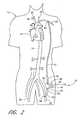
- FIG. 2is a schematic view of a first embodiment of the present invention, shown applied to a patient's circulatory system.
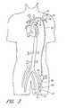
- FIG. 3is a schematic view of a second embodiment of the present invention, shown applied to a patient's circulatory system.
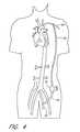
- FIG. 4is a schematic view of a variation of the first embodiment of FIG. 2 shown implanted into a patient;
- FIG. 5is a schematic view of a third embodiment of the present invention, shown applied to a patient's circulatory system.
- FIG. 6is a schematic view of a fourth embodiment of the present invention, shown applied to a patient's circulatory system.
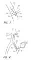
- FIG. 7is a schematic view of an inflow L-shaped connector, shown inserted within a blood vessel.
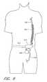
- FIG. 8is a schematic view of a fifth embodiment of the present invention employing a multi-lumen catheter for single site application to a patient.
- FIG. 9is a schematic view of a sixth embodiment of the present invention showing a reservoir and a portable housing for carrying a portion of the invention directly on the patient.
- FIG. 10is a schematic view of a variation of the third embodiment of FIG. 5, shown applied to a patient's circulatory system.
- FIG. 11is a schematic view of an application of the embodiment of FIG. 2 in which the inflow conduit and outflow conduit are applied to the same non-primary blood vessel.
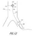
- FIG. 12is a schematic view of a seventh embodiment of the present invention employing an intravascular pump inserted through a non-primary vessel in which the pump is enclosed in a protective housing without inflow and outflow conduits.
- FIG. 13is a schematic view of an eighth embodiment of the present invention employing an intravascular pump inserted through a non-primary vessel in which the pump is housed within a conduit having an inlet and an outlet.
- FIG. 14is a schematic view of a variation of the eighth embodiment of FIG. 13 in which an additional conduit is shown adjacent the conduit housing the pump, and in which the pump comprises a shaft mounted helical thread.
- FIG. 15is a flow chart illustrating one embodiment of a method that provides the benefits discussed herein.
- the present inventionprovides a heart assist system that is extracardiac in nature.
- the present inventionsupplements blood perfusion, without the need to interface directly with the heart and aorta.
- no major invasive surgeryis necessary to use the present invention.
- the present inventionalso lessens the hemodynamic burden or workload on the heart by reducing the pressure at the aortic root during systole (afterload) and/or reducing left ventricular end diastolic pressure and volume (preload).
- a first embodiment of the present invention 10is shown applied to a patient 12 having an ailing heart 14 and an aorta 16 , from which peripheral brachiocephalic blood vessels extend, including the right subclavian 18 , the right carotid 20 , the left carotid 22 , and the left axillary 24 .
- Extending from the descending aortais another set of peripheral blood vessels, the left and right femoral arteries 26 , 28 .
- the first embodiment 10comprises a pump 32 , having an inlet 34 and an outlet 36 for connection of flexible conduits thereto.
- the pump 32is preferably a rotary pump, either an axial type or a centrifugal type, although other types of pumps may be used, whether commercially-available or customized.
- the pumpshould be sufficiently small to be implanted subcutaneously and preferably extrathoracically, for example in the groin area of the patient, without the need for major invasive surgery. Because the present invention is an extracardiac system, no valves are necessary. Any inadvertent backflow through the pump and/or through the inflow conduit would not harm the patient.
- the pump 32 of the present inventionis sized to generate blood flow at subcardiac volumetric rates, less than about 50% of the flow rate of an average healthy heart, although flow rates above that may be effective.
- the pump 32 of the present inventionis sized and configured to discharge blood at volumetric flow rates anywhere in the range of 0.1 to 3 liters per minute, depending upon the application desired and/or the degree of need for heart assist. For example, for a patient experiencing advanced congestive heart failure, it may be preferable to employ a pump that has an average subcardiac rate of 2.5 to 3 liters per minute.
- a pumpthat has an average subcardiac rate of 0.5 liters per minute or less.
- a pumpthat is a pressure wave generator that uses pressure to augment the flow of blood generated by the heart.
- the pump selectedis a continuous flow pump so that blood perfusion through the circulation system is continuous.
- the pump selectedhas the capability of synchronous actuation; i.e., it may be actuated in a pulsatile mode, either in copulsating or counterpulsating fashion.
- the pump 32would be actuated to discharge blood generally during systole, beginning actuation, for example, during isovolumic contraction before the aortic valve opens or as the aortic valve opens.
- the pumpwould be static while the aortic valve is closed following systole, ceasing actuation, for example, when the aortic valve closes.
- the pump 32would be actuated generally during diastole, ceasing actuation, for example, before or during isovolumic contraction. Such an application would permit and/or enhance coronary blood perfusion. In this application, it is contemplated that the pump would be static during the balance of systole after the aortic valve is opened, to lessen the burden against which the heart must pump.
- the aortic valve being openencompasses the periods of opening and closing, wherein blood is flowing therethrough.
- copulsating and counterpulsatingare general identifiers and are not limited to specific points in the patient's heart cycle when the pump begins and discontinues actuation. Rather, they are intended to generally refer to pump actuation in which the pump is actuating, at least in part, during systole and diastole, respectively.
- the pumpmight be activated to be out of phase from true copulsating or counterpulsating actuation described herein, and still be synchronous, depending upon the specific needs of the patient or the desired outcome. One might shift actuation of the pump to begin prior to or after isovolumic contraction or to begin before or after isovolumic expansion.
- the pulsatile pumpmay be actuated to pulsate asynchronously with the patient's heart.
- the patient's heartis beating irregularly, there may be a desire to pulsate the pump asynchronously so that the perfusion of blood by the extracardiac pumping system is more regular and, thus, more effective at oxygenating the organs.
- the patient's heartbeats regularly, but weakly, synchronous pulsation of the extracardiac pump may be preferred.
- the pump 32is driven by a motor 40 and/or other type of drive means and is controlled preferably by a programmable controller 42 that is capable of actuating the pump in pulsatile fashion, where desired, and also of controlling the speed or output of the pump.
- a controller 42is preferably programmed by the use of external means. This may be accomplished, for example, using RF telemetry circuits of the type commonly used within implantable pacemakers and defibrillators.
- the controllermay also be autoregulating to permit automatic regulation of the speed, and/or regulation of the synchronous or asynchronous pulsation of the pump, based upon feedback from ambient sensors monitoring parameters, such as pressure or the patient's EKG. It is also contemplated that a reverse-direction pump be utilized, if desired, in which the controller is capable of reversing the direction of either the drive means or the impellers of the pump. Such a pump might be used where it is desirable to have the option of reversing the direction of circulation between two peripheral blood vessels.
- Power to the motor 40 and controller 42may be provided by a power source 44 , such as a battery, that is preferably rechargeable by an external induction source (not shown), such as an RF induction coil that may be electromagnetically coupled to the battery to induce a charge therein.
- a power source 44such as a battery
- an external induction sourcesuch as an RF induction coil that may be electromagnetically coupled to the battery to induce a charge therein.
- Alternative power sourcesare also possible, including a device that draws energy directly from the patient's body; e.g., the patient's muscles, chemicals or heat.
- the pumpcan be temporarily stopped during recharging with no appreciable life threatening effect, because the system only supplements the heart, rather than substituting for the heart.
- controller 42 and power source 44are preferably pre-assembled to the pump 32 and implanted therewith, it is also contemplated that the pump 32 and motor 40 be implanted at one location and the controller 42 and power source 44 be implanted in a separate location.
- the pump 32may be driven externally through a percutaneous drive line.
- the pump, motor and controllermay be implanted and powered by an extracorporeal power source. In the latter case, the power source could be attached to the side of the patient to permit fully ambulatory movement.
- the inlet 34 of the pump 32is preferably connected to a flexible inflow conduit 50 and a flexible outflow conduit 52 to direct blood flow from one peripheral blood vessel to another.
- the inflow and outflow conduits 50 , 52may, for example, be formed from Dacron, Hemashield or Gortex materials, although other synthetic materials may be suitable.
- the inflow and outflow conduits 50 , 52may also comprise biologic materials or pseudobiological (hybrid) materials (e.g., biologic tissue supported on a synthetic scaffold).
- the inflow and outflow conduitsare preferably configured to minimize kinks so blood flow is not meaningfully interrupted by normal movements of the patient or compressed easily from external forces. In some cases, the inflow and/or outflow conduits may come commercially already attached to the pump. Where it is desired to implant the pump 32 and the conduits 50 , 52 , it is preferable that the inner diameter of the conduits be less than 25 mm, although diameters slightly larger may be effective.
- the first embodimentis applied in an arterial—arterial fashion; for example, as a femoral-axillary connection, as is shown in FIG. 2 .
- a femoral-axillary connectionwould also be effective using the embodiments described herein.
- the present inventionmight be applied to any of the peripheral blood vessels in the patient.
- the first embodimentmay be applied so that the inflow conduit and the outflow conduit are applied subcutaneously to the same non-primary vessel, in any manner described herein.
- the inflow conduit 50has a first proximal end 56 that connects with the inlet 34 of the pump 32 and a second distal end 58 that connects with a first peripheral blood vessel, which is preferably the left femoral artery 26 of the patient 12 , although the right femoral artery or any other peripheral artery may be acceptable.
- a first peripheral blood vesselwhich is preferably the left femoral artery 26 of the patient 12 , although the right femoral artery or any other peripheral artery may be acceptable.
- the connection between the inflow conduit 50 and the first blood vesselis via an end-to-side anastomosis, although a side-to-side anastomosis connection might be used mid-stream of the conduit where the inflow conduit were connected at its second end to an additional blood vessel or at another location on the same blood vessel (neither shown).
- the outflow conduit 52has a first proximal end 62 that connects to the outlet 36 of the pump 32 and a second distal end 64 that connects with a second peripheral blood vessel, preferably the left axillary artery 24 of the patient 12 , although the right axillary artery, or any other peripheral artery, would be acceptable.
- a second peripheral blood vesselpreferably the left axillary artery 24 of the patient 12 , although the right axillary artery, or any other peripheral artery, would be acceptable.
- the connection between the outflow conduit 52 and the second blood vesselis via an end-to-side anastomosis, although a side-to-side anastomosis connection might be used mid-stream of the conduit where the outflow conduit were connected at its second end to yet another blood vessel (not shown) or at another location on the same blood vessel.
- the outflow conduitis attached to the second blood vessel at an angle that results in the predominant flow of blood out of the pump proximally toward the aorta and heart, such as is shown in FIG. 2, while still maintaining sufficient flow distally toward the hand to prevent limb ischemia.
- the present inventionit is preferred that application of the present invention to the peripheral or non-primary blood vessels be accomplished subcutaneously; i.e., at a shallow depth just below the skin or first muscle layer so as to avoid major invasive surgery. It is also preferred that the present invention be applied extrathoracically to avoid the need to invade the patient's chest cavity.
- the entire extracardiac system of the present invention 10may be implanted within the patient 12 , either extravascularly or intravascularly or a hybrid thereof.
- the pump 32may be implanted, for example, into the groin area, with the inflow conduit 50 fluidly connected subcutaneously to, for example, the femoral artery 26 proximate the pump 32 .
- the outflow conduitwould be tunneled subcutaneously through to, for example, the left axillary artery 24 .
- the pump 32 and associated drive and controllercould be temporarily fastened to the exterior skin of the patient, with the inflow and outflow conduits 50 , 52 connected percutaneously. In either case, the patient may be ambulatory without restriction of tethered lines.
- an alternative method of using the present inventioncomprises the steps of fluidly coupling the inflow conduit 50 , which is fluidly coupled to pump 32 , to a patient subcutaneously to a non-primary blood vessel, either via an anastomosis connection or percutaneously with a cannula 54 , fluidly coupling the outflow conduit 52 to the same blood vessel in a desired manner described herein, directing blood from the blood vessel through the inflow conduit, through the pump and the outflow conduit into the blood vessel.
- the systemis positioned at the patient's left femoral artery.
- Specific applications of this alternative methodmay further comprise positioning the inflow conduit upstream of the outflow conduit, although the reverse arrangement is also contemplated.
- either the inflow conduit or the outflow conduitmay extend through the non-primary blood vessel to a second blood vessel (e.g., through the left femoral to the aorta proximate the renal branch) so that blood may be directed from the first to the second blood vessel or vice versa.
- a second blood vessele.g., through the left femoral to the aorta proximate the renal branch
- a special connectormay be used to connect the conduits 50 , 52 to the peripheral blood vessels.
- first and second connectors 68 , 70each comprising three-opening fittings.
- the connectors 68 , 70comprise an intra-vascular, generally-tee-shaped fitting 72 having a proximal end 74 , a distal end 76 , and an angled divergence 78 permitting connection to the inflow and outflow conduits 50 , 52 and the blood vessels.
- the proximal and distal ends 74 , 76 of the fittings 72permit connection to the blood vessel into which the fitting is positioned.
- the angle of divergence 78 of the fittings 72may be 90 degrees or less in either direction from the axis of flow through the blood vessel, as optimally selected to generate the needed flow distally toward the hand to prevent limb ischemia, and to insure sufficient flow and pressure toward the aorta to provide the circulatory assistance and workload reduction needed while minimizing or avoiding endothelial damage to the vessel.
- the connectors 68 , 70are sleeves (not shown) that surround and attach to the outside of the peripheral blood vessel where, within the interior of the sleeve, a port to the blood vessel is provided to permit blood flow from the conduits 50 , 52 when they are connected to the connectors 68 , 70 , respectively.
- an L-shaped connectorbe used if it is desired to withdraw blood more predominantly from one direction of a peripheral vessel or to direct blood more predominantly into a peripheral vessel.
- an inflow conduit 50is fluidly connected to a peripheral vessel, for example, the left femoral artery 26 , using an L-shaped connector 310 .
- the connector 310has an inlet port 312 at a proximal end and an outlet port 314 through which blood flows into the inflow conduit 50 .
- the connector 310also has an arrangement of holes 316 within a wall positioned at a distal end opposite the inlet port 312 so that some of the flow drawn into the connector 310 is diverted through the holes 312 , particularly downstream of the connector, as in this application.
- a single hole in the wallcould also be effective, depending upon size and placement.
- the connectormay be a deformable L-shaped catheter percutaneously applied to the blood vessel or, in an alternative embodiment, be connected directly to the walls of the blood vessel for more long term application. By directing some blood flow downstream of the connector during withdrawal of blood from the vessel, ischemic damage downstream from the connector may be avoided. Such ischemic damage might otherwise occur if the majority of the blood flowing into the inflow connector were diverted from the blood vessel into the inflow conduit. It is also contemplated that a connection to the blood vessels might be made via a cannula, wherein the cannula is implanted, along with the inflow and outflow conduits.
- a connectoreliminates a need for an anastomosis connection between the conduits of the present invention system and the peripheral blood vessels where it is desired to remove and/or replace the system more than one time.
- the connectorscould be applied to the first and second blood vessels semi-permanently, with an end cap applied to the divergence for later quick-connection of the present invention system to the patient.
- a patientmight experience the benefit of the present invention periodically, without having to reconnect and redisconnect the conduits from the blood vessels via an anastomosis procedure each time.
- the end capswould be removed and the conduit attached to the connectors quickly.
- the divergence 78is oriented at an acute angle significantly less than 90° from the axis of the fitting 72 , as shown in FIG. 3, so that a majority of the blood flowing through the outflow conduit 52 into the blood vessel (e.g., left axillary 24 ) flows in a direction proximally toward the heart 14 , rather than in the distal direction.
- the proximal end 74 of the fitting 72may have a diameter larger than the diameter of the distal end 76 , without need of having an angled divergence, to achieve the same result.
- the present inventionmay be applied so to reduce the afterload on the patient's heart, permitting at least partial if not complete CHF recovery, while supplementing blood circulation. Concurrent flow depends upon the phase of operation of the pulsatile pump and the choice of second blood vessel to which the outflow conduit is connected.
- a venous-arterial flow pathmay also be used.
- one embodiment of the present invention 10may be applied to the patient 12 such that the inflow conduit 50 is connected to a peripheral vein, such as the left femoral vein 80 .
- the outflow conduit 50may be connected to one of the peripheral arteries, such as the left axillary 24 .
- Arterial-venous arrangementsare contemplated as well.
- the pump 32should be sized to permit flow sufficiently small so that oxygen-deficient blood does not rise to unacceptable levels in the arteries.
- the connections to the peripheral veinscould be by one or more methods described above for connecting to a peripheral artery.
- the present inventioncould be applied as a venous—venous flow path, wherein the inflow and outflow are connected to separate peripheral veins.
- an alternative embodimentcomprises two discrete pumps and conduit arrangements, one being applied as a venous—venous flow path, and the other as an arterial—arterial flow path.
- the ratio of venous blood to arterial bloodshould be controlled to maintain an arterial saturation of a minimum of 80% at the pump inlet or outlet.
- Arterial saturationcan be measured and/or monitored by pulse oximetry, laser doppler, colorimetry or other methods used to monitor blood oxygen saturation.
- the venous blood flow into the systemcan then be controlled by regulating the amount of blood allowed to pass through the conduit from the venous-side connection.
- a partial external application of the present inventionis contemplated where a patient's heart failure is acute; i.e., is not expected to last long, or in the earlier stages of heart failure (where the patient is in New York Heart Association Classification (NYHAC) functional classes II or III).
- NYHACNew York Heart Association Classification
- a third embodiment of the present invention 110is applied percutaneously to a patient 112 to connect two peripheral blood vessels wherein a pump 132 and its associated driving means and controls are employed extracorporeally.
- the pump 132has an inflow conduit 150 and an outflow conduit 152 associated therewith for connection to two peripheral blood vessels.
- the inflow conduit 150has a first end 156 and second end 158 wherein the second end is connected to a first peripheral blood vessel (e.g., femoral artery 126 ) by way of a cannula 180 .
- the cannula 180has a first end 182 sealably connected to the second end 158 of the inflow conduit 150 .
- the cannula 180also has a second end 184 that is inserted through a surgical opening 186 or an introducer sheath (not shown) and into the blood vessel source (e.g., femoral artery 126 ).
- the outflow conduit 152has a first end 162 and second end 164 wherein the second end is connected to a second peripheral blood vessel (e.g., left axillary artery 124 , as shown in FIG. 5, or the right femoral 127 , as shown in FIG. 10) by way of a cannula 180 .
- a second peripheral blood vessele.g., left axillary artery 124 , as shown in FIG. 5, or the right femoral 127 , as shown in FIG. 10.
- the outflow cannula 180has a first end 182 sealably connected to the second end 164 of the outflow conduit 152 .
- the outflow cannula 180also has a second end 184 that is inserted through surgical opening 190 or an introducer sheath (not shown) and into the second blood vessel (e.g., left axillary artery 124 or right femoral 127 ).
- the second end 184 of the outflow cannulamay extend well into the aorta, for example, proximal to the left subclavian. If desired, it may also terminate within the left subclavian artery or the left axillary artery, or it may terminate in the mesenteric or renal arteries (not shown), where in either case, the cannula has passed through at least a portion of a primary artery (in this case, the aorta).
- blood drawn into the extracardiac system described hereinmay originate from the descending aorta (or an artery branching therefrom) and be directed into a blood vessel that is neither the aorta nor pulmonary artery.
- the present inventionmay be applied temporarily without the need to implant any aspect thereof or to make anastomosis connections to the blood vessels.
- a means for minimizing the loss of thermal energy in the patient's bloodbe provided where the present inventive system is applied extracorporeally.
- Such means for minimizing the loss of thermal energymay comprise, for example, a heated bath through which the inflow and outflow conduits pass or, alternatively, thermal elements secured to the exterior of the inflow and outflow conduits.
- one embodimentcomprises an insulating wrap 402 surrounding the outflow conduit 152 having one or more thermal elements passing therethrough.
- the elementsmay be powered, for example, by a battery (not shown).
- One advantage of thermal elementsis that the patient may be ambulatory, if desired.
- Other means that are known by persons of ordinary skill in the art for ensuring that the temperature of the patient's blood remains at acceptable levels while traveling extracorporeallyare also contemplated.
- An alternative variation of the third embodimentmay be used where it is desired to treat a patient periodically, but for short periods of time each occasion and without the use of special connectors.
- the second ends of the inflow and outflow conduitsbe more permanently connected to the associated blood vessels via, for example, an anastomosis connection, wherein a portion of each conduit proximate to the blood vessel connection is implanted percutaneously with a removable cap enclosing the externally-exposed first end (or an intervening end thereof) of the conduit external to the patient.
- each exposed percutaneously-positioned conduitcould be removed and the pump (or the pump with a length of inflow and/or outflow conduit attached thereto) inserted between the exposed percutaneous conduits.
- a patientmay experience the benefit of the present invention periodically, without having to reconnect and redisconnect the conduits from the blood vessels each time.
- a fourth embodiment of the present invention 210includes a pump 232 in fluid communication with a plurality of inflow conduits 250 A, 250 B and a plurality of outflow conduits 252 A, 252 B.
- Each pair of conduitsconverges at a generally Y-shaped convergence 296 that converges the flow at the inflow end and diverges the flow at the outflow end.
- Each conduitmay be connected to a separate peripheral blood vessel, although it is possible to have two connections to the same blood vessel at remote locations. In one arrangement, all four conduits are connected to peripheral arteries. Alternatively, one or more of the conduits could be connected to veins.
- inflow conduit 250 Ais connected to left femoral artery 226 while inflow conduit 250 B is connected to left femoral vein 278 .
- Outflow conduit 252 Ais connected to left axillary artery 224 while outflow conduit 252 B is connected to left carotid artery 222 .
- the connections of any or all of the conduits to the blood vesselsmay be via an anastomosis connection or via a special connector, as described above.
- the embodiment of FIG. 6may be applied to any combination of peripheral blood vessels that would best suit the patient's condition. For example, it may be desired to have one inflow conduit and two outflow conduits or vice versa. It should be noted that more than two conduits may be used on the inflow or outflow side, where the number of inflow conduits is not necessarily equal to the number of outflow conduits.
- the present inventive systemmay further comprise a reservoir that is either contained within or in fluid communication with the inflow conduit.
- This reservoiris preferably made of materials that are nonthrombogenic.
- a reservoir 420is positioned fluidly in line with the inflow conduit 150 .
- the reservoir 420serves to sustain adequate blood in the system when the pump demand exceeds momentarily the volume of blood available in the peripheral blood vessel in which the inflow conduit resides until the pump output can be adjusted.
- the reservoirreduces the risk of excessive drainage of blood from the peripheral blood vessel, which may occur when cardiac output falls farther than the already diminished baseline level of cardiac output, or when there is systemic vasodilation, as can occur, for example, with septic shock. It is contemplated that the reservoir would be primed with an acceptable solution, such as saline, when the present system is first applied to the patient.
- the present systemcomprises a multi-lumen catheter whereby the system may be applied by insertion at a single cannulated site while the inflow and outflow conduits still fluidly communicate with peripheral vessels.
- a multi-lumen catheter 510could be inserted, for example, into the left femoral artery 26 and guided superiorly through the descending aorta to one of numerous locations.
- the bloodcould discharge, for example, directly into the descending aorta proximate an arterial branch, such as the left subclavian artery or, as shown in FIG. 2 by way of example, directly into the peripheral mesenteric artery 30 .
- the multi-lumen catheter 510has an inflow port 512 that may be positioned within the left femoral artery 26 when the catheter 510 is fully inserted so that blood drawn from the left femoral artery is directed through the inflow port 512 into a first lumen 514 in the catheter. This blood is then pumped through a second lumen 516 in the catheter and out through an outflow port 520 at the distal end of the catheter 510 .
- the outflow port 520may be situated within, for example, the mesenteric artery 30 such that blood flow results from the left femoral artery 26 to the mesenteric artery 30 .
- the multi-lumen catheter 510should preferably be made of material sufficiently flexible and resilient to permit the patient to be comfortably move about while the catheter is indwelling in the patient's blood vessels without causing any vascular trauma.
- one of the advantages of the present heart assist systemis that it permits the patient to be ambulatory.
- the systemmay be designed portably so that it may be carried directly on the patient. Referring to FIG. 9, this may be accomplished through the use of a portable case 610 with a belt strap 612 to house the pump, power supply and/or the controller, along with certain portions of the inflow and/or outflow conduits, if necessary. It may also be accomplished with a shoulder strap or other techniques, such as a backpack or a fanny pack, that permit effective portability.
- bloodis drawn through the inflow conduit 150 into a pump contained within the portable case 610 , where it is discharged into the outflow conduit 152 back into the patient.
- An alternative embodiment of the present inventiontakes further advantage of the supplemental blood perfusion and heart load reduction benefits while remaining minimally invasive in application. Specifically, it is contemplated to provide an extracardiac pumping system that comprises a pump that is sized and configured to be implanted intravascularly in any location desirable to achieve those benefits, while being insertable through a non-primary vessel. Referring to FIG.
- one intrasvascular embodiment 710 of the present inventionis intended for use within a patient's vasculature, as shown, and comprises a pumping means 712 comprising preferably one or more rotatable impeller blades 714 , although other types of pumping means are contemplated, such as an archimedes screw, a worm pump, or other means by which blood may be directed axially along the pumping means from a point upstream of an inlet to the pumping means to a point downstream of an outlet from the pumping means. Where one or more impellers are used, such as a rotary pump, such impellers may be supported helically or otherwise on a shaft 716 within a housing 720 .
- the housing 720may be open, as shown, in which the walls of the housing are open to blood flow therethrough.
- the housingif desired, may be entirely closed except for an inlet and outlet (not shown) to permit blood flow therethrough in a more channel fashion. In either case, the invention serves to supplement the kinetic energy of the blood flow through the blood vessel in which the pump is positioned.
- the pump impeller blade(s) 714 of this embodimentmay be driven in one or a number of ways known to persons of ordinary skill in the art.
- the pump impelleris driven mechanically via a rotatable cable or drive wire 722 by driving means 724 , the latter of which may be positioned corporeally (within or without the vasculature) or extracorporeally.
- the driving means 724may comprise a motor 726 to which energy is supplied directly via an associated battery or an external power source, in a manner described in more detail herein.
- the pumpbe driven electromagnetically through an internal or external electromagnetic drive.
- a controller(not shown) is provided in association with this embodiment so that the pump may be controlled to operate in a continuous and/or pulsatile fashion, as described herein.
- FIGS. 13 and 14Variations of the intravascular embodiment of FIG. 12 are shown in FIGS. 13 and 14.
- the present inventionconsists of an intrasvascular extracardiac system 810 comprising a pumping means 812 , which may be one of several means described herein, whereby the pump means may be driven by one of several pumping means described herein, including means that is sized and configured to be implantable and, if desired, implantable intravascularly.
- a blood vessele.g., descending aorta
- the pumping meanspreferably has a meaningfully smaller diameter “B”.
- the pumping means 812may comprise a pump 814 having an inlet 816 and outlet 820 housed within a conduit 822 , or may comprise a pump and inflow and outflow conduits (not shown) fluidly connected to the inlet and outlets of pump 814 , respectively.
- the conduit 822may be relatively short, as shown, or may extend well within the designated blood vessel or even into an adjoining or remote blood vessel at either the inlet end, the outlet end, or both.
- an intrasvascular pumping meansmay be positioned within one lumen of a multilumen catheter so that, for example, where the catheter is applied at the left femoral artery, a first lumen may extend into the aorta proximate the left subclavian and the pumping means may reside at any point within the first lumen, and the second lumen may extend much shorter just into the left femoral or left iliac.
- the meanscomprises a rotary pump driven mechanically by a drive.
- the intravascular extracardiac systemmay further comprise an additional conduit 830 positioned preferably proximate the pumping means 812 to provide a defined flow path for blood flow axially parallel to the blood flowing through the pumping means.
- the meanscomprises a rotatable cable 834 having blood directing means 836 supported therein for directing blood axially along the cable.
- Other types of pumping meansare also contemplated, if desired, for use with the additional conduit 830 .
- the intravascular extracardiac system described hereinmay be inserted into a patient's vasculature in any means known by one of ordinary skill or obvious variant thereof.
- the systemis temporarily housed within a catheter that is inserted percutaneously, or by surgical cutdown, into a non-primary blood vessel and fed through to a desired location.
- the cathetermay be withdrawn away from the system so as not to interfere with operation of the system, but still permit the withdrawal of the system from the patient when desired.
- An important advantage of the present inventionis its potential to enhance mixing of systemic arterial blood, particularly in the aorta. Such enhanced mixing ensures the delivery of blood with higher oxygen-carrying capacity to organs supplied by arterial side branches off of the aorta.
- a method of enhancing mixing utilizing the present inventionpreferably includes taking steps to assess certain parameters of the patient and then to determine the minimum output of the pump that, when combined with the heart output, ensures turbulent flow in the aorta, thereby enhancing blood mixing.
- Blood flow in the aortic arch during normal cardiac outputmay be characterized as turbulent in the end systolic phase. It is known that turbulence in a flow of fluid through pipes and vessels enhances the uniform distribution of particles within the fluid. It is believed that turbulence in the descending aorta enhances the homogeneity of blood cell distribution in the aorta. It is also known that laminar flow of viscous fluids leads to a higher concentration of particulates in the central portion of pipes and vessels through which the fluid flows. It is believed that, in low flow states such as that experienced during heart failure, there is reduced or inadequate mixing of blood cells leading to a lower concentration of nutrients at the branches of the aorta to peripheral organs and tissues.
- the blood flowing into branch arteries off of the aortawill likely have a lower hematocrit, especially that flowing into the renal arteries, the celiac trunk, the spinal arteries, and the superior and inferior mesenteric arteries. That is because these branches draw from the periphery of the aorta
- the net effect of this phenomenonis that the blood flowing into these branch arteries has a lower oxygen-carrying capacity, because oxygen-carrying capacity is directly proportional to both hematocrit and the fractional O 2 saturation of hemoglobin. Under those circumstances, it is very possible that these organs will experience ischemia-related pathology.
- a method of applying the present invention to a patientmay also include steps to adjust the output of the pump to attain turbulent flow within the descending aorta upstream of the organ branches; i.e., flow exhibiting a peak Reynolds number of at least 2300 within a complete cycle of systole and diastole.
- the method contemplated hereinshould also include the step of calculating the average Womersley number (N W ), which is a function of the frequency of the patient's heart beat. It is desired that a peak Reynolds number of at least 2300 is attained when the corresponding Womersley number for the same blood flow is approximately 6 or above.
- the methodmay comprise calculating the Reynolds number for the blood flow in the descending aorta by determining the blood vessel diameter and both the velocity and viscosity of the fluid flowing through the aorta.
- Vthe velocity of the fluid
- dthe diameter of the vessel
- ⁇the viscosity of the fluid.
- the velocity of the blood flowing through the aortais a function of the cross-sectional area of the aorta and the volume of flow therethrough, the latter of which is contributed both by the patient's own cardiac output and by the output of the pump of the present invention.
- the volume of blood flow Qmay consist only of the patient's cardiac output, with the knowledge that that output will be supplemented by the subcardiac pump that is part of the present invention. If desired, however, the present system can be implemented and applied to the patient first, before calculating Q, which would consist of the combination of cardiac output and the pump output.
- the Womersley numbermay be calculated as follows:
- ris the radius of the vessel being assessed
- ⁇is the frequency of the patient's heartbeat
- ⁇the viscosity of the fluid.
- a Womersley number of at least 6is preferred, although a value as low as 5 would be acceptable.
- ultrasounde.g., echocardiography or abdominal ultrasound
- FIG. 15comprises a step 900 wherein a pump configured to pump blood at subcardiac rates is provided.
- a step 902inflow and outflow conduits configured to fluidly communicate with non-primary blood vessels are provided.
- the inflow conduitis fluidly coupled to a non-primary blood vessel.
- a step 906the outflow conduit is fluidly coupled to the same or different (primary or non-primary) blood vessel.
- the subcardiac pumpis operated in a manner, as described herein, to reduce the load on the heart.
- the fluidly coupling stepsmay comprise anastomosis, percutaneous cannulazation, positioning the distal end of one or both conduits within the desired terminal blood vessel or any combination thereof.
- the methodfurther comprises, after sufficient reduction in ventricular loading, in a step 910 applying a shape change therapy in the form of, for example, a cardiac reshaping device, such as those referred to herein, or others serving the same or similar function, for the purpose of further reducing the size of and/or wall stress on one or more ventricles and, thus, the heart, and/or for the purpose of maintaining the patient's heart at a size sufficient to enhance recovery of the patient's heart.
- a shape change therapyin the form of, for example, a cardiac reshaping device, such as those referred to herein, or others serving the same or similar function, for the purpose of further reducing the size of and/or wall stress on one or more ventricles and, thus, the heart, and/or for the purpose of maintaining the patient's heart at a size sufficient to enhance recovery of the patient's heart.
Landscapes
- Health & Medical Sciences (AREA)
- Engineering & Computer Science (AREA)
- Heart & Thoracic Surgery (AREA)
- Cardiology (AREA)
- Veterinary Medicine (AREA)
- Public Health (AREA)
- Biomedical Technology (AREA)
- Hematology (AREA)
- Life Sciences & Earth Sciences (AREA)
- Animal Behavior & Ethology (AREA)
- General Health & Medical Sciences (AREA)
- Anesthesiology (AREA)
- Mechanical Engineering (AREA)
- Vascular Medicine (AREA)
- Medical Informatics (AREA)
- External Artificial Organs (AREA)
- Control Of Non-Positive-Displacement Pumps (AREA)
- Structures Of Non-Positive Displacement Pumps (AREA)
- Control Of Positive-Displacement Pumps (AREA)
Abstract
Description


Claims (9)
Priority Applications (12)
| Application Number | Priority Date | Filing Date | Title |
|---|---|---|---|
| US10/171,023US6685621B2 (en) | 1997-10-09 | 2002-06-11 | Implantable heart assist system and method of applying same |
| US10/289,467US6889082B2 (en) | 1997-10-09 | 2002-11-06 | Implantable heart assist system and method of applying same |
| US10/729,026US7144365B2 (en) | 1997-10-09 | 2003-12-05 | Implantable heart assist system and method of applying same |
| US10/878,591US7513863B2 (en) | 1997-10-09 | 2004-06-28 | Implantable heart assist system and method of applying same |
| US11/121,352US7458929B2 (en) | 1997-10-09 | 2005-05-03 | Implantable heart assist system and method of applying same |
| US11/417,905US7614997B2 (en) | 1997-10-09 | 2006-05-03 | Implantable heart assist system and method of applying same |
| US11/418,393US20060281962A1 (en) | 1997-10-09 | 2006-05-03 | Implantable heart assist system and method of applying same |
| US11/417,677US7588531B2 (en) | 1997-10-09 | 2006-05-03 | Implantable heart assist system and method of applying same |
| US11/417,889US7591778B2 (en) | 1997-10-09 | 2006-05-03 | Implantable heart assist system and method of applying same |
| US12/565,651US7998054B2 (en) | 1997-10-09 | 2009-09-23 | Implantable heart assist system and method of applying same |
| US12/616,087US7993260B2 (en) | 1997-10-09 | 2009-11-10 | Implantable heart assist system and method of applying same |
| US13/175,735US8900115B2 (en) | 1997-10-09 | 2011-07-01 | Implantable heart assist system and method of applying same |
Applications Claiming Priority (7)
| Application Number | Priority Date | Filing Date | Title |
|---|---|---|---|
| US6143497P | 1997-10-09 | 1997-10-09 | |
| US09/166,005US6200260B1 (en) | 1997-10-09 | 1998-10-02 | Implantable heart assist system |
| US09/289,231US6428464B1 (en) | 1997-10-09 | 1999-04-09 | Implantable heart assist system |
| US09/470,841US6387037B1 (en) | 1997-10-09 | 1999-12-23 | Implantable heart assist system and method of applying same |
| US09/552,979US6390969B1 (en) | 1997-10-09 | 2000-04-21 | Implantable heart assist system and method of applying same |
| US10/078,260US6610004B2 (en) | 1997-10-09 | 2002-02-15 | Implantable heart assist system and method of applying same |
| US10/171,023US6685621B2 (en) | 1997-10-09 | 2002-06-11 | Implantable heart assist system and method of applying same |
Related Parent Applications (2)
| Application Number | Title | Priority Date | Filing Date |
|---|---|---|---|
| US10/078,260Continuation-In-PartUS6610004B2 (en) | 1997-10-09 | 2002-02-15 | Implantable heart assist system and method of applying same |
| US10/078,260ContinuationUS6610004B2 (en) | 1997-10-09 | 2002-02-15 | Implantable heart assist system and method of applying same |
Related Child Applications (1)
| Application Number | Title | Priority Date | Filing Date |
|---|---|---|---|
| US10/289,467Continuation-In-PartUS6889082B2 (en) | 1997-10-09 | 2002-11-06 | Implantable heart assist system and method of applying same |
Publications (2)
| Publication Number | Publication Date |
|---|---|
| US20030088147A1 US20030088147A1 (en) | 2003-05-08 |
| US6685621B2true US6685621B2 (en) | 2004-02-03 |
Family
ID=27752711
Family Applications (7)
| Application Number | Title | Priority Date | Filing Date |
|---|---|---|---|
| US10/078,260Expired - LifetimeUS6610004B2 (en) | 1997-10-09 | 2002-02-15 | Implantable heart assist system and method of applying same |
| US10/171,023Expired - LifetimeUS6685621B2 (en) | 1997-10-09 | 2002-06-11 | Implantable heart assist system and method of applying same |
| US10/408,926Expired - LifetimeUS7125376B2 (en) | 1997-10-09 | 2003-04-07 | Implantable heart assist system and method of applying same |
| US10/878,592Expired - LifetimeUS7331921B2 (en) | 1997-10-09 | 2004-06-28 | Implantable heart assist system and method of applying same |
| US11/417,917AbandonedUS20080275290A1 (en) | 2002-02-15 | 2006-05-03 | Implantable heart assist system and method of applying same |
| US11/418,490AbandonedUS20060270894A1 (en) | 2002-02-15 | 2006-05-03 | Implantable heart assist system and method of applying same |
| US11/418,502AbandonedUS20060264695A1 (en) | 2002-02-15 | 2006-05-03 | Implantable heart assist system and method of applying same |
Family Applications Before (1)
| Application Number | Title | Priority Date | Filing Date |
|---|---|---|---|
| US10/078,260Expired - LifetimeUS6610004B2 (en) | 1997-10-09 | 2002-02-15 | Implantable heart assist system and method of applying same |
Family Applications After (5)
| Application Number | Title | Priority Date | Filing Date |
|---|---|---|---|
| US10/408,926Expired - LifetimeUS7125376B2 (en) | 1997-10-09 | 2003-04-07 | Implantable heart assist system and method of applying same |
| US10/878,592Expired - LifetimeUS7331921B2 (en) | 1997-10-09 | 2004-06-28 | Implantable heart assist system and method of applying same |
| US11/417,917AbandonedUS20080275290A1 (en) | 2002-02-15 | 2006-05-03 | Implantable heart assist system and method of applying same |
| US11/418,490AbandonedUS20060270894A1 (en) | 2002-02-15 | 2006-05-03 | Implantable heart assist system and method of applying same |
| US11/418,502AbandonedUS20060264695A1 (en) | 2002-02-15 | 2006-05-03 | Implantable heart assist system and method of applying same |
Country Status (6)
| Country | Link |
|---|---|
| US (7) | US6610004B2 (en) |
| EP (1) | EP1476207A1 (en) |
| JP (1) | JP2005517502A (en) |
| AU (1) | AU2003215293A1 (en) |
| CA (2) | CA2480467C (en) |
| WO (1) | WO2003070299A1 (en) |
Cited By (42)
| Publication number | Priority date | Publication date | Assignee | Title |
|---|---|---|---|---|
| US20030069468A1 (en)* | 1997-10-09 | 2003-04-10 | Bolling Steven F. | Implantable heart assist system and method of applying same |
| US20030144628A1 (en)* | 2000-12-19 | 2003-07-31 | Laksen Sirimanne | Percutaneous catheter assembly |
| US20040019251A1 (en)* | 1997-10-09 | 2004-01-29 | Anthony Viole | Implantable heart assist system and method of applying same |
| US6761700B2 (en) | 2001-02-09 | 2004-07-13 | Orqis Medical Corporation | Extra-corporeal vascular conduit |
| US20040138519A1 (en)* | 2001-06-06 | 2004-07-15 | Anthony Viole | Multilumen catheter for minimizing limb ischemia |
| US20040152945A1 (en)* | 2003-01-31 | 2004-08-05 | Adrian Kantrowitz | Stable aortic blood pump implant |
| US20040171949A1 (en)* | 2003-01-22 | 2004-09-02 | Uscom Limited | Method and system for the determination of blood characteristics |
| US20050085683A1 (en)* | 2003-10-15 | 2005-04-21 | Bolling Steven F. | Implantable heart assist system and method of applying same |
| US20050085772A1 (en)* | 2000-09-13 | 2005-04-21 | Zafirelis Zafiris G. | Method and system for closed chest blood flow support |
| US20050131385A1 (en)* | 2003-12-12 | 2005-06-16 | Bolling Steven F. | Cannulae for selectively enhancing blood flow |
| US20050228211A1 (en)* | 2004-04-12 | 2005-10-13 | Bryan Leasure | Cyclical pressure coronary assist pump |
| US20050245981A1 (en)* | 2002-07-03 | 2005-11-03 | Phillips Robert A | Pacemaker evaluation method and apparatus |
| US20050277870A1 (en)* | 2004-06-10 | 2005-12-15 | Robert Pecor | Cannula having reduced flow resistance |
| US20050277803A1 (en)* | 2004-06-10 | 2005-12-15 | Robert Pecor | Cannulae having reduced flow resistance |
| US20060047209A1 (en)* | 2002-07-03 | 2006-03-02 | Phillips Robert A | Prosthetic heart function evaluation method and apparatus |
| US20060184199A1 (en)* | 2005-02-14 | 2006-08-17 | O'leary Shawn | Apparatus and methods for reducing bleeding from a cannulation site |
| US20060217588A1 (en)* | 2003-02-24 | 2006-09-28 | Yossi Gross | Fully-implantable cardiac recovery system |
| US20060224110A1 (en)* | 2005-03-17 | 2006-10-05 | Scott Michael J | Methods for minimally invasive vascular access |
| US20060245959A1 (en)* | 2005-04-29 | 2006-11-02 | Larose Jeffrey A | Multiple rotor, wide blade, axial flow pump |
| US20060264689A1 (en)* | 2001-06-06 | 2006-11-23 | Anthony Viole | Multilumen catheter for minimizing limb ischemia |
| US20070078293A1 (en)* | 2005-10-05 | 2007-04-05 | Shambaugh Charles R Jr | Impeller for a rotary ventricular assist device |
| US20070142923A1 (en)* | 2005-11-04 | 2007-06-21 | Ayre Peter J | Control systems for rotary blood pumps |
| US20070161845A1 (en)* | 2006-01-09 | 2007-07-12 | Cardiacassist, Inc. | Percutaneous right ventricular assist apparatus and method |
| US20080132747A1 (en)* | 2006-12-01 | 2008-06-05 | Medical Value Partners, Llc | Medical Device |
| US20080306327A1 (en)* | 2007-06-05 | 2008-12-11 | Medical Value Partners, Llc | Apparatus Comprising a Drive Cable for a Medical Device |
| US20090062597A1 (en)* | 2007-08-29 | 2009-03-05 | Medical Value Partners, Llc | Article Comprising an Impeller |
| US20090112312A1 (en)* | 2007-02-26 | 2009-04-30 | Larose Jeffrey A | Intravascular ventricular assist device |
| US7572217B1 (en) | 2004-06-15 | 2009-08-11 | University Of Louisville Research Foundation, Inc. | System and method for providing cardiac support and promoting myocardial recovery |
| CN1596999B (en)* | 2004-08-20 | 2010-04-28 | 清华大学 | Spiral Wing Type Micro Blood Pump |
| US20110118773A1 (en)* | 2005-07-25 | 2011-05-19 | Rainbow Medical Ltd. | Elliptical device for treating afterload |
| US20110160517A1 (en)* | 2009-12-31 | 2011-06-30 | Cardiacassist, Inc. | System for heart assist, cannula and method |
| US8449443B2 (en) | 2008-10-06 | 2013-05-28 | Indiana University Research And Technology Corporation | Active or passive assistance in the circulatory system |
| US8562509B2 (en) | 2010-12-30 | 2013-10-22 | Cook Medical Technologies Llc | Ventricular assist device |
| US20150297813A1 (en)* | 2012-11-06 | 2015-10-22 | Queen Mary University Of London | Mechanical circulatory support |
| US9339597B2 (en) | 2012-02-07 | 2016-05-17 | Hridaya Inc. | Hemodynamic assist device |
| US9694122B2 (en)* | 2003-01-31 | 2017-07-04 | L-Vad Technology, Inc. | Rigid body aortic blood pump implant |
| US9775936B2 (en) | 2010-10-18 | 2017-10-03 | WorldHeart Corp. | Blood pump with separate mixed-flow and axial-flow impeller stages, components therefor and related methods |
| US10111994B2 (en) | 2013-05-14 | 2018-10-30 | Heartware, Inc. | Blood pump with separate mixed-flow and axial-flow impeller stages and multi-stage stators |
| US11389638B2 (en) | 2012-02-07 | 2022-07-19 | Hridaya, Inc. | Hemodynamic assist device |
| US12246171B2 (en) | 2021-05-03 | 2025-03-11 | Cardiacbooster B.V. | Cardiac assist device with high frequency operation |
| US12427300B1 (en) | 2024-08-06 | 2025-09-30 | Yossi Gross | Pulsatile ventricular assist devices |
| US12427299B1 (en) | 2024-08-06 | 2025-09-30 | Yossi Gross | Pulsatile ventricular assist devices |
Families Citing this family (146)
| Publication number | Priority date | Publication date | Assignee | Title |
|---|---|---|---|---|
| US7091412B2 (en) | 2002-03-04 | 2006-08-15 | Nanoset, Llc | Magnetically shielded assembly |
| US7162302B2 (en) | 2002-03-04 | 2007-01-09 | Nanoset Llc | Magnetically shielded assembly |
| JP4248811B2 (en)* | 2002-07-11 | 2009-04-02 | 健太郎 長田 | Tightening band |
| AU2003285221B2 (en)* | 2002-12-17 | 2008-06-26 | Rodney James Lane | Blood pumping system and procedure |
| ES2545328T3 (en) | 2003-03-14 | 2015-09-10 | Depuy Spine, Inc. | Bone cement hydraulic injection device in percutaneous vertebroplasty |
| US8066713B2 (en) | 2003-03-31 | 2011-11-29 | Depuy Spine, Inc. | Remotely-activated vertebroplasty injection device |
| US8415407B2 (en) | 2004-03-21 | 2013-04-09 | Depuy Spine, Inc. | Methods, materials, and apparatus for treating bone and other tissue |
| US7416525B2 (en) | 2003-09-18 | 2008-08-26 | Myrakelle, Llc | Rotary blood pump |
| US8579908B2 (en) | 2003-09-26 | 2013-11-12 | DePuy Synthes Products, LLC. | Device for delivering viscous material |
| US7762977B2 (en) | 2003-10-08 | 2010-07-27 | Hemosphere, Inc. | Device and method for vascular access |
| US7273446B2 (en)* | 2003-10-31 | 2007-09-25 | Spence Paul A | Methods, devices and systems for counterpulsation of blood flow to and from the circulatory system |
| US20050113631A1 (en)* | 2003-11-12 | 2005-05-26 | Bolling Steven F. | Cannulae having a redirecting tip |
| WO2005074384A2 (en)* | 2004-02-10 | 2005-08-18 | Yossi Gross | Extracardiac blood flow amplification device |
| JP4521547B2 (en)* | 2004-04-15 | 2010-08-11 | 株式会社サンメディカル技術研究所 | Blood pump flow estimation device |
| CN101065080B (en) | 2004-07-30 | 2021-10-29 | 德普伊新特斯产品有限责任公司 | Materials and Instruments for Manipulating Bone and Other Tissues |
| EP2151257B1 (en) | 2004-08-13 | 2013-04-17 | Delgado, Reynolds M., III | Apparatus for long-term assisting a left ventricle to pump blood |
| US7828711B2 (en)* | 2004-08-16 | 2010-11-09 | Cardiac Pacemakers, Inc. | Method and apparatus for modulating cellular growth and regeneration using ventricular assist device |
| US7393181B2 (en) | 2004-09-17 | 2008-07-01 | The Penn State Research Foundation | Expandable impeller pump |
| ITMI20051420A1 (en)* | 2005-07-22 | 2007-01-23 | A N B Technology S R L | CARDIOCIRCULATORY ASSISTANCE DEVICE |
| US9381024B2 (en) | 2005-07-31 | 2016-07-05 | DePuy Synthes Products, Inc. | Marked tools |
| US9918767B2 (en) | 2005-08-01 | 2018-03-20 | DePuy Synthes Products, Inc. | Temperature control system |
| US8360629B2 (en) | 2005-11-22 | 2013-01-29 | Depuy Spine, Inc. | Mixing apparatus having central and planetary mixing elements |
| US20070142696A1 (en)* | 2005-12-08 | 2007-06-21 | Ventrassist Pty Ltd | Implantable medical devices |
| US8672611B2 (en) | 2006-01-13 | 2014-03-18 | Heartware, Inc. | Stabilizing drive for contactless rotary blood pump impeller |
| EP1977110B8 (en) | 2006-01-13 | 2018-12-26 | HeartWare, Inc. | Rotary blood pump |
| CN102380135A (en) | 2006-03-23 | 2012-03-21 | 宾州研究基金会 | Heart assist device with expandable impeller pump |
| KR20090074110A (en) | 2006-03-31 | 2009-07-06 | 오퀴스 메디컬 코포레이션 | Rotary Blood Pump |
| EP2023852A4 (en)* | 2006-06-09 | 2012-06-27 | Univ California | BIOMIMETIC SKELETONS RELATED TO A BIOMOLECULE |
| AU2007297097A1 (en) | 2006-09-14 | 2008-03-20 | Depuy Spine, Inc. | Bone cement and methods of use thereof |
| US8950929B2 (en) | 2006-10-19 | 2015-02-10 | DePuy Synthes Products, LLC | Fluid delivery system |
| US9504774B2 (en)* | 2007-10-01 | 2016-11-29 | Minvasc Devices, Llc | Intraatrial ventricular assist device |
| US20110295181A1 (en) | 2008-03-05 | 2011-12-01 | Hemosphere, Inc. | Implantable and removable customizable body conduit |
| JP5492792B2 (en) | 2008-03-05 | 2014-05-14 | ヘモスフィア,インコーポレイテッド | Vascular access system |
| WO2009118499A1 (en)* | 2008-03-26 | 2009-10-01 | Cardio Assist Limited | Heart assist device |
| JP5171953B2 (en) | 2008-06-23 | 2013-03-27 | テルモ株式会社 | Blood pump device |
| WO2010025411A2 (en)* | 2008-08-28 | 2010-03-04 | Orqis Medical Corporation | Implantable heart assist system |
| EP2372160B1 (en) | 2008-12-08 | 2014-07-30 | Thoratec Corporation | Centrifugal pump device |
| US8905961B2 (en)* | 2008-12-19 | 2014-12-09 | St. Jude Medical, Inc. | Systems, apparatuses, and methods for cardiovascular conduits and connectors |
| US20100160939A1 (en)* | 2008-12-19 | 2010-06-24 | St. Jude Medical, Inc. | Systems, apparatuses, and methods for cardiovascular cutting devices and valves |
| US8728012B2 (en)* | 2008-12-19 | 2014-05-20 | St. Jude Medical, Inc. | Apparatus and method for measuring blood vessels |
| US9566146B2 (en)* | 2008-12-19 | 2017-02-14 | St. Jude Medical, Inc. | Cardiovascular valve and valve housing apparatuses and systems |
| JP5378010B2 (en) | 2009-03-05 | 2013-12-25 | ソラテック コーポレーション | Centrifugal pump device |
| CN102341600B (en) | 2009-03-06 | 2014-12-10 | 胸腔科技有限公司 | Centrifugal pump device |
| CN102481398A (en) | 2009-07-01 | 2012-05-30 | 宾夕法尼亚州研究基金会 | Blood pump with expandable cannula |
| US8821365B2 (en) | 2009-07-29 | 2014-09-02 | Thoratec Corporation | Rotation drive device and centrifugal pump apparatus using the same |
| CA2768567C (en) | 2009-09-14 | 2017-03-21 | Circulite, Inc. | Endovascular anastomotic connector device, delivery system, and methods of delivery and use |
| JP5443197B2 (en) | 2010-02-16 | 2014-03-19 | ソラテック コーポレーション | Centrifugal pump device |
| KR101845213B1 (en)* | 2010-02-17 | 2018-05-18 | 플로우 포워드 메디컬, 인크. | System and method to increase the overall diameter of veins |
| US8579788B2 (en)* | 2010-03-08 | 2013-11-12 | Wilmo Orejola | Auto-regulated R-wave synchronized intraventricular balloon pump heart assist device |
| JP5572832B2 (en) | 2010-03-26 | 2014-08-20 | ソーラテック コーポレイション | Centrifugal blood pump device |
| JP5681403B2 (en) | 2010-07-12 | 2015-03-11 | ソーラテック コーポレイション | Centrifugal pump device |
| WO2012033847A1 (en) | 2010-09-07 | 2012-03-15 | Spence Paul A | Cannula systems and methods |
| JP5577506B2 (en) | 2010-09-14 | 2014-08-27 | ソーラテック コーポレイション | Centrifugal pump device |
| US8485961B2 (en) | 2011-01-05 | 2013-07-16 | Thoratec Corporation | Impeller housing for percutaneous heart pump |
| US8597170B2 (en) | 2011-01-05 | 2013-12-03 | Thoratec Corporation | Catheter pump |
| WO2012094641A2 (en) | 2011-01-06 | 2012-07-12 | Thoratec Corporation | Percutaneous heart pump |
| WO2012094535A2 (en) | 2011-01-06 | 2012-07-12 | Thoratec Corporation | Percutaneous heart pump |
| EP2693609B1 (en) | 2011-03-28 | 2017-05-03 | Thoratec Corporation | Rotation and drive device and centrifugal pump device using same |
| JP6199866B2 (en) | 2011-09-06 | 2017-09-20 | メリット・メディカル・システムズ・インコーポレイテッドMerit Medical Systems,Inc. | Vascular access system having a connecting portion |
| JP6139550B2 (en) | 2011-11-28 | 2017-05-31 | ミ‐ヴァド インコーポレイテッド | Auxiliary circulation apparatus and method |
| JP6083929B2 (en) | 2012-01-18 | 2017-02-22 | ソーラテック コーポレイション | Centrifugal pump device |
| EP2830675B1 (en) | 2012-03-26 | 2025-06-25 | Procyrion, Inc. | Systems and methods for fluid flows and/or pressures for circulation and perfusion enhancement |
| US20180200599A1 (en)* | 2012-04-19 | 2018-07-19 | The Bicycle Corporation Pty Ltd | Cycling accessory and method of use |
| US9446179B2 (en) | 2012-05-14 | 2016-09-20 | Thoratec Corporation | Distal bearing support |
| US8721517B2 (en) | 2012-05-14 | 2014-05-13 | Thoratec Corporation | Impeller for catheter pump |
| EP4218887A1 (en) | 2012-05-14 | 2023-08-02 | Tc1 Llc | Mechanical circulatory support device for stabilizing a patient after cardiogenic shock |
| US9872947B2 (en) | 2012-05-14 | 2018-01-23 | Tc1 Llc | Sheath system for catheter pump |
| US9327067B2 (en) | 2012-05-14 | 2016-05-03 | Thoratec Corporation | Impeller for catheter pump |
| US9358329B2 (en) | 2012-07-03 | 2016-06-07 | Thoratec Corporation | Catheter pump |
| US9421311B2 (en) | 2012-07-03 | 2016-08-23 | Thoratec Corporation | Motor assembly for catheter pump |
| EP4186557A1 (en) | 2012-07-03 | 2023-05-31 | Tc1 Llc | Motor assembly for catheter pump |
| US10342905B2 (en) | 2012-09-13 | 2019-07-09 | Circulite, Inc. | Blood flow system with variable speed control |
| EP2908880B1 (en) | 2012-10-16 | 2018-12-05 | Paul A. Spence | Devices for facilitating flow from the heart to a blood pump |
| US9371826B2 (en) | 2013-01-24 | 2016-06-21 | Thoratec Corporation | Impeller position compensation using field oriented control |
| US9556873B2 (en) | 2013-02-27 | 2017-01-31 | Tc1 Llc | Startup sequence for centrifugal pump with levitated impeller |
| US11077294B2 (en) | 2013-03-13 | 2021-08-03 | Tc1 Llc | Sheath assembly for catheter pump |
| US11033728B2 (en) | 2013-03-13 | 2021-06-15 | Tc1 Llc | Fluid handling system |
| WO2014164136A1 (en) | 2013-03-13 | 2014-10-09 | Thoratec Corporation | Fluid handling system |
| US9308302B2 (en) | 2013-03-15 | 2016-04-12 | Thoratec Corporation | Catheter pump assembly including a stator |
| EP4190376A1 (en) | 2013-03-15 | 2023-06-07 | Tc1 Llc | Catheter pump assembly including a stator |
| US10052420B2 (en) | 2013-04-30 | 2018-08-21 | Tc1 Llc | Heart beat identification and pump speed synchronization |
| US9713663B2 (en) | 2013-04-30 | 2017-07-25 | Tc1 Llc | Cardiac pump with speed adapted for ventricle unloading |
| US9320841B2 (en)* | 2013-06-21 | 2016-04-26 | Corvivo, Inc. | Ventricular assist device |
| US9814816B2 (en) | 2013-06-21 | 2017-11-14 | Corvivo, Inc. | Artificial ventricles |
| WO2015017770A1 (en) | 2013-08-02 | 2015-02-05 | Circulite, Inc. | Implantable system with secure remote control |
| EP3076884B1 (en) | 2013-12-04 | 2020-02-05 | Heartware, Inc. | Apparatus for cutting an atrial wall |
| US10682453B2 (en) | 2013-12-20 | 2020-06-16 | Merit Medical Systems, Inc. | Vascular access system with reinforcement member |
| EP3110468B1 (en) | 2014-02-25 | 2021-11-03 | Kushwaha, Sudhir | Ventricular assist device and method |
| EP3131597B1 (en) | 2014-04-15 | 2020-12-02 | Tc1 Llc | Catheter pump introducer systems |
| US10583232B2 (en) | 2014-04-15 | 2020-03-10 | Tc1 Llc | Catheter pump with off-set motor position |
| WO2015160943A1 (en) | 2014-04-15 | 2015-10-22 | Thoratec Corporation | Sensors for catheter pumps |
| EP3131599B1 (en) | 2014-04-15 | 2019-02-20 | Tc1 Llc | Catheter pump with access ports |
| EP3583973A1 (en) | 2014-08-18 | 2019-12-25 | Tc1 Llc | Guide features for percutaneous catheter pump |
| US9623161B2 (en) | 2014-08-26 | 2017-04-18 | Tc1 Llc | Blood pump and method of suction detection |
| US9717832B2 (en) | 2015-01-06 | 2017-08-01 | HeartWave, Inc. | Axial flow rotor with downstream bearing wash flow |
| US9675738B2 (en) | 2015-01-22 | 2017-06-13 | Tc1 Llc | Attachment mechanisms for motor of catheter pump |
| WO2016118781A2 (en) | 2015-01-22 | 2016-07-28 | Thoratec Corporation | Motor assembly with heat exchanger for catheter pump |
| US9770543B2 (en) | 2015-01-22 | 2017-09-26 | Tc1 Llc | Reduced rotational mass motor assembly for catheter pump |
| EP3256183B1 (en) | 2015-02-11 | 2025-08-13 | Tc1 Llc | Heart beat identification and pump speed synchronization |
| US10371152B2 (en) | 2015-02-12 | 2019-08-06 | Tc1 Llc | Alternating pump gaps |
| EP3256185B1 (en) | 2015-02-12 | 2019-10-30 | Tc1 Llc | System and method for controlling the position of a levitated rotor |
| EP3256184B1 (en) | 2015-02-13 | 2020-04-08 | Tc1 Llc | Impeller suspension mechanism for heart pump |
| US9907890B2 (en) | 2015-04-16 | 2018-03-06 | Tc1 Llc | Catheter pump with positioning brace |
| EP4290081A3 (en) | 2015-09-25 | 2024-02-21 | Procyrion, Inc. | Non-occluding intravascular blood pump providing reduced hemolysis |
| US10117983B2 (en) | 2015-11-16 | 2018-11-06 | Tc1 Llc | Pressure/flow characteristic modification of a centrifugal pump in a ventricular assist device |
| US11160970B2 (en) | 2016-07-21 | 2021-11-02 | Tc1 Llc | Fluid seals for catheter pump motor assembly |
| EP3808401A1 (en) | 2016-07-21 | 2021-04-21 | Tc1 Llc | Gas-filled chamber for catheter pump motor assembly |
| WO2018089625A2 (en) | 2016-11-10 | 2018-05-17 | Merit Medical Systems, Inc. | Anchor device for vascular anastomosis |
| US11383072B2 (en) | 2017-01-12 | 2022-07-12 | Merit Medical Systems, Inc. | Methods and systems for selection and use of connectors between conduits |
| EP4461262A3 (en) | 2017-01-25 | 2025-02-26 | Merit Medical Systems, Inc. | Systems for facilitating laminar flow between conduits |
| EP3366332A1 (en)* | 2017-02-22 | 2018-08-29 | Berlin Heart GmbH | Device and method for connecting two blood vessel sections |
| US11026704B2 (en) | 2017-03-06 | 2021-06-08 | Merit Medical Systems, Inc. | Vascular access assembly declotting systems and methods |
| AU2018239421B2 (en)* | 2017-03-21 | 2023-03-16 | Abiomed, Inc. | System and method for determining native cardiac output while continuing support to the heart with a catheter-mounted intracardiac blood pump having an imbedded thermistor |
| US10925710B2 (en) | 2017-03-24 | 2021-02-23 | Merit Medical Systems, Inc. | Subcutaneous vascular assemblies for improving blood flow and related devices and methods |
| US10926013B2 (en)* | 2017-04-07 | 2021-02-23 | Ecp Entwicklungsgesellschaft Mbh | Methods and systems for an external drive unit for an implantable heart assist pump |
| CA3066361A1 (en) | 2017-06-07 | 2018-12-13 | Shifamed Holdings, Llc | Intravascular fluid movement devices, systems, and methods of use |
| US11221373B2 (en) | 2017-06-23 | 2022-01-11 | Pacesetter, Inc. | Method and device for detecting early battery depletion condition |
| WO2019014444A2 (en) | 2017-07-14 | 2019-01-17 | Merit Medical Systems, Inc. | Releasable conduit connectors |
| US11911585B2 (en) | 2017-07-20 | 2024-02-27 | Merit Medical Systems, Inc. | Methods and systems for coupling conduits |
| JP7233069B2 (en)* | 2017-09-14 | 2023-03-06 | 株式会社ニューロシューティカルズiVNS | Myocardial infarction treatment control device and myocardial infarction treatment control method |
| US11331458B2 (en) | 2017-10-31 | 2022-05-17 | Merit Medical Systems, Inc. | Subcutaneous vascular assemblies for improving blood flow and related devices and methods |
| WO2019094963A1 (en) | 2017-11-13 | 2019-05-16 | Shifamed Holdings, Llc | Intravascular fluid movement devices, systems, and methods of use |
| CN112004563B (en) | 2018-02-01 | 2024-08-06 | 施菲姆德控股有限责任公司 | Intravascular blood pump and methods of use and manufacture |
| DE102018208538A1 (en) | 2018-05-30 | 2019-12-05 | Kardion Gmbh | Intravascular blood pump and process for the production of electrical conductors |
| DE102018208862A1 (en) | 2018-06-06 | 2019-12-12 | Kardion Gmbh | Implantable vascular support system |
| DE102018208945A1 (en)* | 2018-06-06 | 2019-12-12 | Kardion Gmbh | An analysis device and method for analyzing a viscosity of a fluid |
| DE102018208936A1 (en) | 2018-06-06 | 2019-12-12 | Kardion Gmbh | Determining device and method for determining a viscosity of a fluid |
| DE102018208913A1 (en) | 2018-06-06 | 2019-12-12 | Kardion Gmbh | A method of operating an implanted ventricular assist device |
| DE102018208879A1 (en) | 2018-06-06 | 2020-01-30 | Kardion Gmbh | Method for determining a total fluid volume flow in the area of an implanted, vascular support system |
| DE102018208899A1 (en) | 2018-06-06 | 2019-12-12 | Kardion Gmbh | A method for determining the speed of sound in a fluid in the region of an implanted vascular support system |
| DE102018208933A1 (en) | 2018-06-06 | 2019-12-12 | Kardion Gmbh | A method of determining a flow rate of fluid flowing through an implanted vascular support system |
| DE102018208929A1 (en) | 2018-06-06 | 2019-12-12 | Kardion Gmbh | A method of determining a flow rate of fluid flowing through an implanted vascular support system |
| DE102018210076A1 (en) | 2018-06-21 | 2019-12-24 | Kardion Gmbh | Method and device for detecting a state of wear of a cardiac support system, method and device for operating a cardiac support system and cardiac support system |
| US12161857B2 (en) | 2018-07-31 | 2024-12-10 | Shifamed Holdings, Llc | Intravascular blood pumps and methods of use |
| JP7233077B2 (en)* | 2018-09-28 | 2023-03-06 | 国立大学法人東北大学 | blood circulation device |
| WO2020073047A1 (en) | 2018-10-05 | 2020-04-09 | Shifamed Holdings, Llc | Intravascular blood pumps and methods of use |
| JP7684904B2 (en) | 2019-02-01 | 2025-05-28 | カルディアテック エスエー | Pressure unloading left ventricular assist device and method for assisting the human heart - Patents.com |
| WO2021011473A1 (en) | 2019-07-12 | 2021-01-21 | Shifamed Holdings, Llc | Intravascular blood pumps and methods of manufacture and use |
| US11654275B2 (en) | 2019-07-22 | 2023-05-23 | Shifamed Holdings, Llc | Intravascular blood pumps with struts and methods of use and manufacture |
| EP4501393A3 (en) | 2019-09-25 | 2025-04-09 | Shifamed Holdings, LLC | Catheter blood pumps and collapsible pump housings |
| WO2021062265A1 (en) | 2019-09-25 | 2021-04-01 | Shifamed Holdings, Llc | Intravascular blood pump systems and methods of use and control thereof |
| US12121713B2 (en) | 2019-09-25 | 2024-10-22 | Shifamed Holdings, Llc | Catheter blood pumps and collapsible blood conduits |
| IL293625A (en) | 2019-12-03 | 2022-08-01 | Procyrion Inc | blood pumps |
| EP4072650A4 (en) | 2019-12-11 | 2024-01-10 | Shifamed Holdings, LLC | Descending aorta and vena cava blood pumps |
| WO2021119413A1 (en) | 2019-12-13 | 2021-06-17 | Procyrion, Inc. | Support structures for intravascular blood pumps |
| CN116549762B (en)* | 2023-07-10 | 2023-10-31 | 北京悦唯医疗科技有限责任公司 | Left ventricle auxiliary device |
Citations (108)
| Publication number | Priority date | Publication date | Assignee | Title |
|---|---|---|---|---|
| US2876769A (en) | 1955-10-11 | 1959-03-10 | Cordova Jose Juan | Apparatus for oxygenating, centrifuging and changing the temperature of blood |
| US2935068A (en) | 1955-08-04 | 1960-05-03 | Donaldson John Shearman | Surgical procedure and apparatus for use in carrying out the same |
| US3017885A (en) | 1959-03-30 | 1962-01-23 | Robicsek Francis | Blood flow meter |
| US3592184A (en) | 1969-12-16 | 1971-07-13 | David H Watkins | Heart assist method and catheter |
| US3692018A (en) | 1970-02-11 | 1972-09-19 | Robert H Goetz | Cardiac assistance device |
| US3835864A (en) | 1970-09-21 | 1974-09-17 | Rasor Ass Inc | Intra-cardiac stimulator |
| US3885251A (en) | 1973-03-05 | 1975-05-27 | Philips Corp | Artificial heart pump or assist |
| US3939820A (en) | 1974-10-29 | 1976-02-24 | Datascope Corporation | Single-chamber, multi-section balloon for cardiac assistance |
| US3964479A (en) | 1974-11-20 | 1976-06-22 | Cobe Laboratories, Inc. | Extracorporeal blood circulation system and drip chamber with adjustable blood level |
| US4004299A (en) | 1976-02-12 | 1977-01-25 | Runge Thomas M | Cardiac replacement and assist devices |
| US4034742A (en) | 1973-01-31 | 1977-07-12 | Thoma Dipl Ing Dr Techn Herwig | Apparatus for mechanically assisting circulation of the blood in the human body |
| US4047849A (en) | 1976-01-09 | 1977-09-13 | Thermo Electron Corporation | Pneumatic pulsator pumping system with pulsator fluid venting valve |
| US4051840A (en) | 1976-01-05 | 1977-10-04 | Sinai Hospital Of Detroit | Dynamic aortic patch |
| US4077394A (en) | 1976-08-25 | 1978-03-07 | Mccurdy Martin D | Integral pressure sensor probe for a cardiac assistance device |
| US4080958A (en) | 1976-02-27 | 1978-03-28 | Datascope Corporation | Apparatus for aiding and improving the blood flow in patients |
| US4135496A (en) | 1976-01-30 | 1979-01-23 | Institut Kardiologii Imeni A.L. Myasnikova Akademii Meditsinskikh Nauk Sssr | Extracorporeal circulation apparatus |
| US4143616A (en) | 1977-03-18 | 1979-03-13 | Robertshaw Controls Company | Process machinery control system and individual safety control systems therefor or the like |
| US4154227A (en) | 1977-10-11 | 1979-05-15 | Krause Horst E | Method and apparatus for pumping blood within a vessel |
| US4167046A (en) | 1977-12-12 | 1979-09-11 | Andros, Inc. | Blood pumping device |
| US4240409A (en) | 1979-02-21 | 1980-12-23 | Thermo Electron Corporation | Apparatus for assisting circulation of blood |
| US4302854A (en) | 1980-06-04 | 1981-12-01 | Runge Thomas M | Electrically activated ferromagnetic/diamagnetic vascular shunt for left ventricular assist |
| US4384829A (en) | 1980-11-28 | 1983-05-24 | Andros Incorporated | Pump and actuator mechanism |
| US4407271A (en) | 1980-07-28 | 1983-10-04 | Peter Schiff | Apparatus for left heart assist |
| US4457673A (en) | 1980-11-28 | 1984-07-03 | Novacor Medical Corporation | Pump and actuator mechanism |
| US4459977A (en) | 1981-03-27 | 1984-07-17 | Veronique Pizon | Coronary sinus retroperfusion apparatus for the treatment of myocardial ischemia |
| US4522195A (en) | 1981-05-25 | 1985-06-11 | Peter Schiff | Apparatus for left heart assist |
| US4546759A (en) | 1983-07-29 | 1985-10-15 | Mladen Solar | Method and apparatus for assisting human heart function |
| US4552522A (en) | 1983-12-23 | 1985-11-12 | Amhil Enterprises Ltd. | Segmented spacer ring |
| US4569332A (en) | 1983-04-13 | 1986-02-11 | Peter Schiff | Method and apparatus for treating a heart patient through the coordinating efforts of balloon pumping and dispensing catheters |
| US4573997A (en) | 1984-03-19 | 1986-03-04 | Research Corporation | Right ventricular assist device |
| US4611578A (en) | 1983-05-03 | 1986-09-16 | Forschungsgesellschaft fur Biomedizinischs Technik E.V. Goethestrasse | Redundant piston pump for the operation of single or multiple chambered pneumatic blood pumps |
| GB2174151A (en) | 1985-04-22 | 1986-10-29 | Bard Inc C R | Blood retroperfusion system |
| US4625712A (en) | 1983-09-28 | 1986-12-02 | Nimbus, Inc. | High-capacity intravascular blood pump utilizing percutaneous access |
| US4666443A (en) | 1986-04-18 | 1987-05-19 | Novacor Medical Corporation | Biventricular circulatory assist system and method |
| US4685446A (en) | 1984-02-21 | 1987-08-11 | Choy Daniel S J | Method for using a ventricular assist device |
| US4688998A (en) | 1981-03-18 | 1987-08-25 | Olsen Don B | Magnetically suspended and rotated impellor pump apparatus and method |
| US4690134A (en) | 1985-07-01 | 1987-09-01 | Snyders Robert V | Ventricular assist device |
| US4697574A (en) | 1985-02-20 | 1987-10-06 | Medicorp Research Laboratories Corp. | Pump for assistance in circulation |
| US4719921A (en) | 1985-08-28 | 1988-01-19 | Raul Chirife | Cardiac pacemaker adaptive to physiological requirements |
| US4756302A (en) | 1986-11-20 | 1988-07-12 | Novacor Medical Corporation | Blood pumping system and method |
| US4759760A (en) | 1986-10-30 | 1988-07-26 | Snapp Jr Edward A | Cardiovascular pump system |
| US4771765A (en) | 1984-02-21 | 1988-09-20 | Choy Daniel S J | Heart assist device and method of use |
| US4822357A (en) | 1987-04-29 | 1989-04-18 | Articor Limited | Auxiliary artificial heart |
| US4838889A (en) | 1981-09-01 | 1989-06-13 | University Of Utah Research Foundation | Ventricular assist device and method of manufacture |
| US4861330A (en) | 1987-03-12 | 1989-08-29 | Gene Voss | Cardiac assist device and method |
| US4872874A (en) | 1987-05-29 | 1989-10-10 | Taheri Syde A | Method and apparatus for transarterial aortic graft insertion and implantation |
| US4883462A (en) | 1987-01-30 | 1989-11-28 | Baxter Travenol Laboratories, Inc. | Blood extraction assist apparatus and method |
| US4895150A (en) | 1988-03-24 | 1990-01-23 | Nu-Tech Industries, Inc. | Implanted power source |
| US4902272A (en) | 1987-06-17 | 1990-02-20 | Abiomed Cardiovascular, Inc. | Intra-arterial cardiac support system |
| US4902273A (en) | 1984-02-21 | 1990-02-20 | Choy Daniel S J | Heart assist device |
| US4906229A (en) | 1988-05-03 | 1990-03-06 | Nimbus Medical, Inc. | High-frequency transvalvular axisymmetric blood pump |
| US4908012A (en) | 1988-08-08 | 1990-03-13 | Nimbus Medical, Inc. | Chronic ventricular assist system |
| US4927407A (en) | 1989-06-19 | 1990-05-22 | Regents Of The University Of Minnesota | Cardiac assist pump with steady rate supply of fluid lubricant |
| US4957504A (en) | 1988-12-02 | 1990-09-18 | Chardack William M | Implantable blood pump |
| US4968293A (en) | 1989-03-20 | 1990-11-06 | Medtronic, Inc. | Circulatory assist device |
| EP0405749A1 (en) | 1989-06-30 | 1991-01-02 | Steven J. Phillips | Ventricular assist device cannulae |
| US4994078A (en) | 1988-02-17 | 1991-02-19 | Jarvik Robert K | Intraventricular artificial hearts and methods of their surgical implantation and use |
| US4995856A (en) | 1989-06-14 | 1991-02-26 | Pudenz-Schulte Medical Research Corporation | Ventriculostomy reservoir |
| US4995857A (en) | 1989-04-07 | 1991-02-26 | Arnold John R | Left ventricular assist device and method for temporary and permanent procedures |
| EP0232074B1 (en) | 1986-01-30 | 1991-04-17 | Sherwood Medical Company | Medical tube |
| US5020516A (en) | 1988-03-31 | 1991-06-04 | Cardiopulmonary Corporation | Circulatory assist method and apparatus |
| US5059167A (en) | 1987-05-29 | 1991-10-22 | Retroperfusion Systems, Inc. | Retroperfusion and retroinfusion control apparatus, system and method |
| US5069662A (en) | 1988-10-21 | 1991-12-03 | Delcath Systems, Inc. | Cancer treatment |
| US5089017A (en) | 1989-01-17 | 1992-02-18 | Young David B | Drive system for artificial hearts and left-ventricular assist devices |
| US5092844A (en) | 1990-04-10 | 1992-03-03 | Mayo Foundation For Medical Education And Research | Intracatheter perfusion pump apparatus and method |
| US5098370A (en) | 1988-01-29 | 1992-03-24 | Galram Technology Industries, Inc. | Heart assist device |
| US5116564A (en) | 1988-10-11 | 1992-05-26 | Josef Jansen | Method of producing a closing member having flexible closing elements, especially a heart valve |
| US5129878A (en) | 1989-09-28 | 1992-07-14 | Toyo Boseki Kabushiki Kaisha | Auxiliary circulation apparatus and method of its driving |
| US5131905A (en) | 1990-07-16 | 1992-07-21 | Grooters Ronald K | External cardiac assist device |
| US5133744A (en) | 1989-04-26 | 1992-07-28 | Wilson Ramos Martinez | Tubular-valued artificial heart |
| US5147281A (en) | 1990-04-23 | 1992-09-15 | Advanced Medical Systems, Inc. | Biological fluid pumping means and method |
| US5147388A (en) | 1990-03-08 | 1992-09-15 | Kenji Yamazaki | Auxiliary artificial heart of the embedded-in-body type |
| US5169378A (en) | 1990-07-20 | 1992-12-08 | Diego Figuera | Intra-ventricular expansible assist pump |
| US5169379A (en) | 1989-06-14 | 1992-12-08 | L-Vad Technology | In-series ventricular assist system and method of controlling same |
| US5171207A (en) | 1991-04-03 | 1992-12-15 | Whalen Biomedical, Inc. | Apparatus and method of use for pulsatile blood flow |
| US5176619A (en) | 1989-05-05 | 1993-01-05 | Jacob Segalowitz | Heart-assist balloon pump with segmented ventricular balloon |
| US5211659A (en) | 1990-11-05 | 1993-05-18 | Strimling Walter E | Pump system suitable as a heart assist device |
| US5263978A (en) | 1991-09-10 | 1993-11-23 | Forschungsgesellschaft Fur Biomedizinische Technik E.V. | Blood pump for pulsating operation |
| US5267940A (en) | 1989-11-29 | 1993-12-07 | The Administrators Of The Tulane Educational Fund | Cardiovascular flow enhancer and method of operation |
| US5273518A (en) | 1992-01-31 | 1993-12-28 | Medtronic, Inc. | Cardiac assist apparatus |
| US5290227A (en) | 1992-08-06 | 1994-03-01 | Pasque Michael K | Method of implanting blood pump in ascending aorta or main pulmonary artery |
| US5300113A (en) | 1990-03-20 | 1994-04-05 | Ministero Dell'universita E Della Ricerca Scientifica E Tecnologica | Cardiac ventricular assistance device particularly for compensating for weakened heart muscle function and for maintaining the vital body functions |
| US5332403A (en) | 1992-08-17 | 1994-07-26 | Jack Kolff | LVAD with t-shape and unidirectional valve |
| US5346458A (en) | 1990-06-25 | 1994-09-13 | Klaus Affeld | Electrohydraulic energy converter for cardiac assist devices and artificial hearts |
| US5352180A (en) | 1990-02-09 | 1994-10-04 | Societe Teracor | Method and apparatus for regulating the flow rate of a periodic flow heart prosthesis |
| US5374239A (en) | 1992-08-04 | 1994-12-20 | Metatech Corporation | Arterial shunt with blood flow indicator |
| US5413549A (en) | 1993-10-07 | 1995-05-09 | Datascope Investment Corp. | Devices and methods for efficient intra-aortic balloon pumping |
| EP0411605B1 (en) | 1989-08-04 | 1995-06-07 | Terumo Kabushiki Kaisha | Catheter and assembly for extracorporeal circulation |
| US5429584A (en) | 1990-11-09 | 1995-07-04 | Mcgill University | Cardiac assist method and apparatus |
| US5433731A (en) | 1993-03-29 | 1995-07-18 | Pacesetter Ab | Mechanical defibrillator and method for defibrillating a heart |
| US5437601A (en) | 1992-03-03 | 1995-08-01 | Runge; Thomas M. | Blood conduit and pulsatile cardiopulmonary bypass pump system |
| US5453076A (en) | 1992-04-17 | 1995-09-26 | Kiyota; Yoshiharu | Internal cardiac assist apparatus |
| US5503615A (en) | 1994-08-26 | 1996-04-02 | Goldstein; Bernard | Implantable cardiac ventricular assist device and controller thereof |
| US5511958A (en) | 1994-02-10 | 1996-04-30 | Baxter International, Inc. | Blood pump system |
| US5514073A (en) | 1991-06-27 | 1996-05-07 | Nippon Zeon Co., Ltd. | Intra-aortic balloon catheter |
| US5533958A (en) | 1993-06-17 | 1996-07-09 | Wilk; Peter J. | Intrapericardial assist device and associated method |
| US5562595A (en) | 1995-08-17 | 1996-10-08 | Medtronic, Inc. | Multiple therapy cardiac assist device having battery voltage safety monitor |
| US5584804A (en) | 1990-10-10 | 1996-12-17 | Life Resuscitation Technologies, Inc. | Brain resuscitation and organ preservation device and method for performing the same |
| US5746575A (en) | 1993-06-25 | 1998-05-05 | Baxter International, Inc. | Blood pump as centrifugal pump |
| US5749855A (en) | 1992-09-02 | 1998-05-12 | Reitan; Oyvind | Catheter pump |
| US5824070A (en) | 1995-10-30 | 1998-10-20 | Jarvik; Robert | Hybrid flow blood pump |
| US5851174A (en) | 1996-09-17 | 1998-12-22 | Robert Jarvik | Cardiac support device |
| US5941813A (en) | 1996-07-23 | 1999-08-24 | Cardiotools Herzchirurgietechnik Gmbh | Cardiac assist device |
| US6085754A (en) | 1998-07-13 | 2000-07-11 | Acorn Cardiovascular, Inc. | Cardiac disease treatment method |
| US6183411B1 (en) | 1998-09-21 | 2001-02-06 | Myocor, Inc. | External stress reduction device and method |
| US6190408B1 (en) | 1998-03-05 | 2001-02-20 | The University Of Cincinnati | Device and method for restructuring the heart chamber geometry |
| US6221103B1 (en) | 1996-01-02 | 2001-04-24 | The University Of Cincinnati | Device and method for restructuring heart chamber geometry |
| US6224540B1 (en) | 1995-06-13 | 2001-05-01 | Abiomed, Inc. | Passive girdle for heart ventricle for therapeutic aid to patients having ventricular dilatation |
Family Cites Families (115)
| Publication number | Priority date | Publication date | Assignee | Title |
|---|---|---|---|---|
| CH461033D (en) | 1965-05-13 | |||
| FR2201908B1 (en) | 1972-10-10 | 1975-06-13 | Thomson Medical Telco | |
| US3939850A (en)* | 1973-12-10 | 1976-02-24 | Wahl Clipper Corporation | Hair comb and dryer device |
| US3938530A (en) | 1974-11-15 | 1976-02-17 | Santomieri Louis | Catheter |
| US4000739A (en) | 1975-07-09 | 1977-01-04 | Cordis Corporation | Hemostasis cannula |
| US4134402A (en) | 1976-02-11 | 1979-01-16 | Mahurkar Sakharam D | Double lumen hemodialysis catheter |
| US4375941A (en) | 1978-03-20 | 1983-03-08 | Child Frank W | Method and apparatus for pumping blood |
| DE3010841A1 (en) | 1980-03-21 | 1981-10-08 | Ulrich Dr.med. 6936 Haag Uthmann | CATHEDER |
| US4411655A (en) | 1981-11-30 | 1983-10-25 | Schreck David M | Apparatus and method for percutaneous catheterization |
| US4405313A (en) | 1982-01-29 | 1983-09-20 | Sisley James R | Figure-eight, dual-lumen catheter and method of using |
| US4447236A (en) | 1982-02-05 | 1984-05-08 | Cordis Corporation | Infusion catheter system |
| DE3205449C2 (en) | 1982-02-16 | 1985-10-17 | Fresenius AG, 6380 Bad Homburg | Device for purifying metabolic products from the blood |
| US4692141A (en) | 1982-03-08 | 1987-09-08 | Mahurkar Sakharam D | Double lumen catheter |
| DE3214397C2 (en) | 1982-04-20 | 1984-07-26 | Karl Dr. 6301 Pohlheim Aigner | Double lumen perfusion catheter |
| US4464164A (en) | 1982-09-24 | 1984-08-07 | Extracorporeal Medical Specialties, Inc. | Flowrate control for a blood flow system |
| JPS59218159A (en) | 1983-05-27 | 1984-12-08 | 日本ゼオン株式会社 | Sac-shaped blood pump |
| US4543087A (en) | 1983-11-14 | 1985-09-24 | Quinton Instrument Company | Double lumen catheter tip |
| US4934996A (en) | 1984-02-27 | 1990-06-19 | Boston Scientific Corporation | Pressure-controlled intermittent coronary sinus occlusion apparatus and method |
| US4610656A (en) | 1984-08-21 | 1986-09-09 | Mehealus Partnership | Fully portable semi-automatic mechanical heart-lung substitution system and method |
| JPS62142568A (en) | 1985-12-18 | 1987-06-25 | 日本シヤ−ウツド株式会社 | Catheter obturator |
| CA1330285C (en) | 1987-12-22 | 1994-06-21 | Geoffrey S. Martin | Triple lumen catheter |
| US4944745A (en) | 1988-02-29 | 1990-07-31 | Scimed Life Systems, Inc. | Perfusion balloon catheter |
| US4925452A (en) | 1988-03-08 | 1990-05-15 | Uresil Corporation | Multiple conduit drainage device |
| US4857062A (en) | 1988-03-09 | 1989-08-15 | Medical Parameters, Inc. | Catheter introducer valve |
| US5011469A (en) | 1988-08-29 | 1991-04-30 | Shiley, Inc. | Peripheral cardiopulmonary bypass and coronary reperfusion system |
| US4976270A (en) | 1989-03-28 | 1990-12-11 | Vanderbilt University | Apparatus for continuously sampling plasma |
| JPH02286170A (en) | 1989-04-27 | 1990-11-26 | Terumo Corp | Exocirculating device |
| US5041098A (en) | 1989-05-19 | 1991-08-20 | Strato Medical Corporation | Vascular access system for extracorporeal treatment of blood |
| US4995865A (en) | 1989-06-09 | 1991-02-26 | Worldwide Medical Plastics Inc. | Multi-lumen catheters |
| US4985014A (en) | 1989-07-11 | 1991-01-15 | Orejola Wilmo C | Ventricular venting loop |
| US5569182A (en) | 1990-01-08 | 1996-10-29 | The Curators Of The University Of Missouri | Clot resistant multiple lumen catheter and method |
| US5066285A (en) | 1990-01-26 | 1991-11-19 | Cordis Corporation | Catheter introducer sheath made of expanded polytetrafluoroethylene |
| US5211546A (en)* | 1990-05-29 | 1993-05-18 | Nu-Tech Industries, Inc. | Axial flow blood pump with hydrodynamically suspended rotor |
| CA2022019C (en) | 1990-07-26 | 1992-12-29 | Michael Black | Catheter |
| US5087247A (en) | 1990-08-28 | 1992-02-11 | Cardiovascular Designs, Inc. | Balloon perfusion catheter |
| US5114408A (en) | 1990-10-18 | 1992-05-19 | Daig Corporation | Universal hemostasis valve having improved sealing characteristics |
| FR2671283B1 (en) | 1991-01-08 | 1995-05-12 | Alain Durand | INTRAVASCULAR MULTI-LIGHT CATHETER, LIKELY TO BE IMPLANTED WITH TUNNELLING. |
| DE4126886A1 (en) | 1991-08-14 | 1993-02-18 | Hp Medica Gmbh | RINSING CATHETER |
| JP2713515B2 (en) | 1991-09-17 | 1998-02-16 | 禎祐 山内 | Catheter device |
| US5449342A (en) | 1991-09-30 | 1995-09-12 | Nippon Zeon Co., Ltd. | Apparatus for assisting blood circulation |
| US5672158A (en) | 1992-01-07 | 1997-09-30 | Sherwood Medical Company | Catheter introducer |
| US5279551A (en) | 1992-01-29 | 1994-01-18 | Vascular Products, Inc. | Trocar catheter |
| US5676651A (en)* | 1992-08-06 | 1997-10-14 | Electric Boat Corporation | Surgically implantable pump arrangement and method for pumping body fluids |
| US5536250A (en) | 1994-04-01 | 1996-07-16 | Localmed, Inc. | Perfusion shunt device and method |
| US5250036A (en) | 1992-11-24 | 1993-10-05 | Mohammad Farivar | Intravenous catheter placement system |
| US5972030A (en) | 1993-02-22 | 1999-10-26 | Heartport, Inc. | Less-invasive devices and methods for treatment of cardiac valves |
| US5336205A (en) | 1993-02-25 | 1994-08-09 | Target Therapeutics, Inc. | Flow directed catheter |
| US5417705A (en) | 1993-05-14 | 1995-05-23 | Habley Medical Technology Corp. | Obturator with rotating, resettable safety shield |
| US5453084A (en) | 1993-05-19 | 1995-09-26 | Moses; John A. | Vascular graft with internal shunt |
| US5344402A (en) | 1993-06-30 | 1994-09-06 | Cardiovascular Dynamics, Inc. | Low profile perfusion catheter |
| US5403291A (en) | 1993-08-02 | 1995-04-04 | Quinton Instrument Company | Catheter with elongated side holes |
| US5486159A (en) | 1993-10-01 | 1996-01-23 | Mahurkar; Sakharam D. | Multiple-lumen catheter |
| US5378230A (en) | 1993-11-01 | 1995-01-03 | Mahurkar; Sakharam D. | Triple-lumen critical care catheter |
| ES2077519B1 (en)* | 1993-11-22 | 1996-07-01 | Fernandez De Lomana Euge Anaya | INTRAAORTIC CATHETER FOR RENAL PERFUSION AND CONSERVATION. |
| US5597377A (en)* | 1994-05-06 | 1997-01-28 | Trustees Of Boston University | Coronary sinus reperfusion catheter |
| US5542937A (en) | 1994-06-24 | 1996-08-06 | Target Therapeutics, Inc. | Multilumen extruded catheter |
| US5505710A (en) | 1994-08-22 | 1996-04-09 | C. R. Bard, Inc. | Telescoping probe |
| US5554136A (en) | 1994-09-07 | 1996-09-10 | Luther Medical Products, Inc. | Dual lumen infusion/aspiration catheter |
| US5571093A (en) | 1994-09-21 | 1996-11-05 | Cruz; Cosme | Multiple-lumen catheter |
| EP0711574A1 (en) | 1994-11-10 | 1996-05-15 | Med-Pro Design, Inc. | Catheter with dual round lumens |
| US5613935A (en) | 1994-12-16 | 1997-03-25 | Jarvik; Robert | High reliability cardiac assist system |
| US5556390A (en) | 1995-03-07 | 1996-09-17 | Quinton Instrument Company | Catheter with oval or elliptical lumens |
| AU7431396A (en) | 1995-10-26 | 1997-05-15 | Medisystems Technology Corporation | Pressure measurement in blood treatment |
| US6228052B1 (en) | 1996-02-29 | 2001-05-08 | Medtronic Inc. | Dilator for introducer system having injection port |
| US5911685A (en) | 1996-04-03 | 1999-06-15 | Guidant Corporation | Method and apparatus for cardiac blood flow assistance |
| US5868703A (en) | 1996-04-10 | 1999-02-09 | Endoscopic Technologies, Inc. | Multichannel catheter |
| US5746709A (en)* | 1996-04-25 | 1998-05-05 | Medtronic, Inc. | Intravascular pump and bypass assembly and method for using the same |
| US5688245A (en) | 1996-05-02 | 1997-11-18 | Runge; Thomas M. | Cannula system for a biventricular cardiac support system or a cardiopulmonary bypass system |
| US5649911A (en) | 1996-05-17 | 1997-07-22 | Indiana University Foundation | Intravenous catheter and delivery system |
| ES2227718T3 (en) | 1996-10-04 | 2005-04-01 | United States Surgical Corporation | CIRCULATORY SUPPORT SYSTEM. |
| US5776111A (en) | 1996-11-07 | 1998-07-07 | Medical Components, Inc. | Multiple catheter assembly |
| US5807311A (en) | 1996-11-29 | 1998-09-15 | Palestrant; Aubrey M. | Dialysis catheter having rigid and collapsible lumens and related method |
| US5795326A (en) | 1997-01-29 | 1998-08-18 | Baxter International Inc. | Double lumen tubing design for catheter |
| US6102884A (en) | 1997-02-07 | 2000-08-15 | Squitieri; Rafael | Squitieri hemodialysis and vascular access systems |
| US5964694A (en) | 1997-04-02 | 1999-10-12 | Guidant Corporation | Method and apparatus for cardiac blood flow assistance |
| US6532964B2 (en) | 1997-07-11 | 2003-03-18 | A-Med Systems, Inc. | Pulmonary and circulatory blood flow support devices and methods for heart surgery procedures |
| US5947953A (en) | 1997-08-06 | 1999-09-07 | Hemocleanse, Inc. | Splittable multiple catheter assembly and methods of inserting the same |
| US6059760A (en) | 1997-08-14 | 2000-05-09 | Medtronic, Inc. | Cannula having reverse flow tip |
| US6371935B1 (en) | 1999-01-22 | 2002-04-16 | Cardeon Corporation | Aortic catheter with flow divider and methods for preventing cerebral embolization |
| JP4544741B2 (en) | 1997-10-01 | 2010-09-15 | ボストン サイエンティフィック リミテッド | Percutaneous catheter with slip hub |
| US6387037B1 (en)* | 1997-10-09 | 2002-05-14 | Orqis Medical Corporation | Implantable heart assist system and method of applying same |
| US6610004B2 (en) | 1997-10-09 | 2003-08-26 | Orqis Medical Corporation | Implantable heart assist system and method of applying same |
| US6889082B2 (en) | 1997-10-09 | 2005-05-03 | Orqis Medical Corporation | Implantable heart assist system and method of applying same |
| UA56262C2 (en)* | 1997-10-09 | 2003-05-15 | Орквіс Медікел Корпорейшн | Extracardiac pumping system for supplementing blood circulation |
| US6390969B1 (en)* | 1997-10-09 | 2002-05-21 | Orqis Medical Corporation | Implantable heart assist system and method of applying same |
| US6135981A (en) | 1997-10-22 | 2000-10-24 | Dyke; Charles C. | Protective aortic occlusion catheter |
| US6120480A (en) | 1997-10-28 | 2000-09-19 | Medtronic Ave, Inc. | Catheter introducer |
| US5928181A (en)* | 1997-11-21 | 1999-07-27 | Advanced International Technologies, Inc. | Cardiac bypass catheter system and method of use |
| US6044845A (en) | 1998-02-03 | 2000-04-04 | Salient Interventional Systems, Inc. | Methods and systems for treating ischemia |
| JP4612186B2 (en) | 1998-02-24 | 2011-01-12 | ナビリスト メディカル, インコーポレイテッド | High flow dialysis catheter and related methods |
| US6086527A (en)* | 1998-04-02 | 2000-07-11 | Scimed Life Systems, Inc. | System for treating congestive heart failure |
| US6508777B1 (en)* | 1998-05-08 | 2003-01-21 | Cardeon Corporation | Circulatory support system and method of use for isolated segmental perfusion |
| US6083198A (en) | 1998-06-25 | 2000-07-04 | Cardiovention, Inc. | Perfusion catheter providing segmented flow regions and methods of use |
| US6167765B1 (en) | 1998-09-25 | 2001-01-02 | The Regents Of The University Of Michigan | System and method for determining the flow rate of blood in a vessel using doppler frequency signals |
| US6068588A (en)* | 1999-01-07 | 2000-05-30 | International Business Machines Corporation | Counterbalanced pump |
| US7780628B1 (en)* | 1999-01-11 | 2010-08-24 | Angiodynamics, Inc. | Apparatus and methods for treating congestive heart disease |
| US6749598B1 (en)* | 1999-01-11 | 2004-06-15 | Flowmedica, Inc. | Apparatus and methods for treating congestive heart disease |
| US6161547A (en) | 1999-01-15 | 2000-12-19 | Coaxia, Inc. | Medical device for flow augmentation in patients with occlusive cerebrovascular disease and methods of use |
| US6743196B2 (en) | 1999-03-01 | 2004-06-01 | Coaxia, Inc. | Partial aortic occlusion devices and methods for cerebral perfusion augmentation |
| US6245045B1 (en) | 1999-04-23 | 2001-06-12 | Alexander Andrew Stratienko | Combination sheath and catheter for cardiovascular use |
| US9814869B1 (en) | 1999-06-15 | 2017-11-14 | C.R. Bard, Inc. | Graft-catheter vascular access system |
| US6190304B1 (en)* | 1999-07-13 | 2001-02-20 | University Of North Texas Health Science Center At Fort Worth | Enhanced intra-aortic balloon assist device |
| US6136025A (en) | 1999-07-27 | 2000-10-24 | Barbut; Denise R. | Endoscopic arterial pumps for treatment of cardiac insufficiency and venous pumps for right-sided cardiac support |
| US6592567B1 (en) | 1999-12-07 | 2003-07-15 | Chf Solutions, Inc. | Kidney perfusion catheter |
| US6514226B1 (en) | 2000-02-10 | 2003-02-04 | Chf Solutions, Inc. | Method and apparatus for treatment of congestive heart failure by improving perfusion of the kidney |
| DE10016422B4 (en) | 2000-04-01 | 2013-10-31 | Impella Cardiosystems Ag | Paracardiac blood pump |
| US6287608B1 (en) | 2000-04-11 | 2001-09-11 | Intellicardia, Inc. | Method and apparatus for treatment of congestive heart failure by improving perfusion of the kidney by infusion of a vasodilator |
| US6719749B1 (en) | 2000-06-01 | 2004-04-13 | Medical Components, Inc. | Multilumen catheter assembly and methods for making and inserting the same |
| US6488662B2 (en) | 2000-12-19 | 2002-12-03 | Laksen Sirimanne | Percutaneous catheter assembly |
| US6761700B2 (en) | 2001-02-09 | 2004-07-13 | Orqis Medical Corporation | Extra-corporeal vascular conduit |
| WO2002070039A2 (en) | 2001-03-01 | 2002-09-12 | Three Arch Partners | Intravascular device for treatment of hypertension |
| US7048680B2 (en) | 2001-06-06 | 2006-05-23 | Orqis Medical Corporation | Multilumen catheter for minimizing limb ischemia |
| US20020188167A1 (en) | 2001-06-06 | 2002-12-12 | Anthony Viole | Multilumen catheter for minimizing limb ischemia |
| US6942633B2 (en) | 2002-03-22 | 2005-09-13 | Twin Star Medical, Inc. | System for treating tissue swelling |
| US20050085683A1 (en) | 2003-10-15 | 2005-04-21 | Bolling Steven F. | Implantable heart assist system and method of applying same |
- 2002
- 2002-02-15USUS10/078,260patent/US6610004B2/ennot_activeExpired - Lifetime
- 2002-06-11USUS10/171,023patent/US6685621B2/ennot_activeExpired - Lifetime
- 2003
- 2003-02-14JPJP2003569252Apatent/JP2005517502A/enactivePending
- 2003-02-14CACA2480467Apatent/CA2480467C/ennot_activeExpired - Fee Related
- 2003-02-14AUAU2003215293Apatent/AU2003215293A1/ennot_activeAbandoned
- 2003-02-14CACA2785934Apatent/CA2785934A1/ennot_activeAbandoned
- 2003-02-14EPEP03711112Apatent/EP1476207A1/ennot_activeWithdrawn
- 2003-02-14WOPCT/US2003/004853patent/WO2003070299A1/ennot_activeApplication Discontinuation
- 2003-04-07USUS10/408,926patent/US7125376B2/ennot_activeExpired - Lifetime
- 2004
- 2004-06-28USUS10/878,592patent/US7331921B2/ennot_activeExpired - Lifetime
- 2006
- 2006-05-03USUS11/417,917patent/US20080275290A1/ennot_activeAbandoned
- 2006-05-03USUS11/418,490patent/US20060270894A1/ennot_activeAbandoned
- 2006-05-03USUS11/418,502patent/US20060264695A1/ennot_activeAbandoned
Patent Citations (109)
| Publication number | Priority date | Publication date | Assignee | Title |
|---|---|---|---|---|
| US2935068A (en) | 1955-08-04 | 1960-05-03 | Donaldson John Shearman | Surgical procedure and apparatus for use in carrying out the same |
| US2876769A (en) | 1955-10-11 | 1959-03-10 | Cordova Jose Juan | Apparatus for oxygenating, centrifuging and changing the temperature of blood |
| US3017885A (en) | 1959-03-30 | 1962-01-23 | Robicsek Francis | Blood flow meter |
| US3592184A (en) | 1969-12-16 | 1971-07-13 | David H Watkins | Heart assist method and catheter |
| US3692018A (en) | 1970-02-11 | 1972-09-19 | Robert H Goetz | Cardiac assistance device |
| US3835864A (en) | 1970-09-21 | 1974-09-17 | Rasor Ass Inc | Intra-cardiac stimulator |
| US4034742A (en) | 1973-01-31 | 1977-07-12 | Thoma Dipl Ing Dr Techn Herwig | Apparatus for mechanically assisting circulation of the blood in the human body |
| US3885251A (en) | 1973-03-05 | 1975-05-27 | Philips Corp | Artificial heart pump or assist |
| US3939820A (en) | 1974-10-29 | 1976-02-24 | Datascope Corporation | Single-chamber, multi-section balloon for cardiac assistance |
| US3964479A (en) | 1974-11-20 | 1976-06-22 | Cobe Laboratories, Inc. | Extracorporeal blood circulation system and drip chamber with adjustable blood level |
| US4051840A (en) | 1976-01-05 | 1977-10-04 | Sinai Hospital Of Detroit | Dynamic aortic patch |
| US4047849A (en) | 1976-01-09 | 1977-09-13 | Thermo Electron Corporation | Pneumatic pulsator pumping system with pulsator fluid venting valve |
| US4135496A (en) | 1976-01-30 | 1979-01-23 | Institut Kardiologii Imeni A.L. Myasnikova Akademii Meditsinskikh Nauk Sssr | Extracorporeal circulation apparatus |
| US4004299A (en) | 1976-02-12 | 1977-01-25 | Runge Thomas M | Cardiac replacement and assist devices |
| US4080958A (en) | 1976-02-27 | 1978-03-28 | Datascope Corporation | Apparatus for aiding and improving the blood flow in patients |
| US4077394A (en) | 1976-08-25 | 1978-03-07 | Mccurdy Martin D | Integral pressure sensor probe for a cardiac assistance device |
| US4143616A (en) | 1977-03-18 | 1979-03-13 | Robertshaw Controls Company | Process machinery control system and individual safety control systems therefor or the like |
| US4154227A (en) | 1977-10-11 | 1979-05-15 | Krause Horst E | Method and apparatus for pumping blood within a vessel |
| US4167046A (en) | 1977-12-12 | 1979-09-11 | Andros, Inc. | Blood pumping device |
| US4240409A (en) | 1979-02-21 | 1980-12-23 | Thermo Electron Corporation | Apparatus for assisting circulation of blood |
| US4302854A (en) | 1980-06-04 | 1981-12-01 | Runge Thomas M | Electrically activated ferromagnetic/diamagnetic vascular shunt for left ventricular assist |
| US4407271A (en) | 1980-07-28 | 1983-10-04 | Peter Schiff | Apparatus for left heart assist |
| US4384829A (en) | 1980-11-28 | 1983-05-24 | Andros Incorporated | Pump and actuator mechanism |
| US4457673A (en) | 1980-11-28 | 1984-07-03 | Novacor Medical Corporation | Pump and actuator mechanism |
| US4688998A (en) | 1981-03-18 | 1987-08-25 | Olsen Don B | Magnetically suspended and rotated impellor pump apparatus and method |
| US4459977A (en) | 1981-03-27 | 1984-07-17 | Veronique Pizon | Coronary sinus retroperfusion apparatus for the treatment of myocardial ischemia |
| US4522195A (en) | 1981-05-25 | 1985-06-11 | Peter Schiff | Apparatus for left heart assist |
| US4838889A (en) | 1981-09-01 | 1989-06-13 | University Of Utah Research Foundation | Ventricular assist device and method of manufacture |
| US4569332A (en) | 1983-04-13 | 1986-02-11 | Peter Schiff | Method and apparatus for treating a heart patient through the coordinating efforts of balloon pumping and dispensing catheters |
| US4611578A (en) | 1983-05-03 | 1986-09-16 | Forschungsgesellschaft fur Biomedizinischs Technik E.V. Goethestrasse | Redundant piston pump for the operation of single or multiple chambered pneumatic blood pumps |
| US4546759A (en) | 1983-07-29 | 1985-10-15 | Mladen Solar | Method and apparatus for assisting human heart function |
| US4625712A (en) | 1983-09-28 | 1986-12-02 | Nimbus, Inc. | High-capacity intravascular blood pump utilizing percutaneous access |
| US4552522A (en) | 1983-12-23 | 1985-11-12 | Amhil Enterprises Ltd. | Segmented spacer ring |
| US4902273A (en) | 1984-02-21 | 1990-02-20 | Choy Daniel S J | Heart assist device |
| US4685446A (en) | 1984-02-21 | 1987-08-11 | Choy Daniel S J | Method for using a ventricular assist device |
| US4771765A (en) | 1984-02-21 | 1988-09-20 | Choy Daniel S J | Heart assist device and method of use |
| US4573997A (en) | 1984-03-19 | 1986-03-04 | Research Corporation | Right ventricular assist device |
| US4697574A (en) | 1985-02-20 | 1987-10-06 | Medicorp Research Laboratories Corp. | Pump for assistance in circulation |
| GB2174151A (en) | 1985-04-22 | 1986-10-29 | Bard Inc C R | Blood retroperfusion system |
| US4690134A (en) | 1985-07-01 | 1987-09-01 | Snyders Robert V | Ventricular assist device |
| US4719921A (en) | 1985-08-28 | 1988-01-19 | Raul Chirife | Cardiac pacemaker adaptive to physiological requirements |
| EP0232074B1 (en) | 1986-01-30 | 1991-04-17 | Sherwood Medical Company | Medical tube |
| US4666443A (en) | 1986-04-18 | 1987-05-19 | Novacor Medical Corporation | Biventricular circulatory assist system and method |
| US4759760A (en) | 1986-10-30 | 1988-07-26 | Snapp Jr Edward A | Cardiovascular pump system |
| US4756302A (en) | 1986-11-20 | 1988-07-12 | Novacor Medical Corporation | Blood pumping system and method |
| US4883462A (en) | 1987-01-30 | 1989-11-28 | Baxter Travenol Laboratories, Inc. | Blood extraction assist apparatus and method |
| US4861330A (en) | 1987-03-12 | 1989-08-29 | Gene Voss | Cardiac assist device and method |
| US4822357A (en) | 1987-04-29 | 1989-04-18 | Articor Limited | Auxiliary artificial heart |
| US4872874A (en) | 1987-05-29 | 1989-10-10 | Taheri Syde A | Method and apparatus for transarterial aortic graft insertion and implantation |
| US5059167A (en) | 1987-05-29 | 1991-10-22 | Retroperfusion Systems, Inc. | Retroperfusion and retroinfusion control apparatus, system and method |
| US4902272A (en) | 1987-06-17 | 1990-02-20 | Abiomed Cardiovascular, Inc. | Intra-arterial cardiac support system |
| US5098370A (en) | 1988-01-29 | 1992-03-24 | Galram Technology Industries, Inc. | Heart assist device |
| US4994078A (en) | 1988-02-17 | 1991-02-19 | Jarvik Robert K | Intraventricular artificial hearts and methods of their surgical implantation and use |
| US4895150A (en) | 1988-03-24 | 1990-01-23 | Nu-Tech Industries, Inc. | Implanted power source |
| US5020516A (en) | 1988-03-31 | 1991-06-04 | Cardiopulmonary Corporation | Circulatory assist method and apparatus |
| US4906229A (en) | 1988-05-03 | 1990-03-06 | Nimbus Medical, Inc. | High-frequency transvalvular axisymmetric blood pump |
| US4908012A (en) | 1988-08-08 | 1990-03-13 | Nimbus Medical, Inc. | Chronic ventricular assist system |
| US5116564A (en) | 1988-10-11 | 1992-05-26 | Josef Jansen | Method of producing a closing member having flexible closing elements, especially a heart valve |
| US5376113A (en) | 1988-10-11 | 1994-12-27 | Jansen; Josef | Closing member having flexible closing elements, especially a heart valve |
| US5069662A (en) | 1988-10-21 | 1991-12-03 | Delcath Systems, Inc. | Cancer treatment |
| US4957504A (en) | 1988-12-02 | 1990-09-18 | Chardack William M | Implantable blood pump |
| US5089017A (en) | 1989-01-17 | 1992-02-18 | Young David B | Drive system for artificial hearts and left-ventricular assist devices |
| US4968293A (en) | 1989-03-20 | 1990-11-06 | Medtronic, Inc. | Circulatory assist device |
| US4995857A (en) | 1989-04-07 | 1991-02-26 | Arnold John R | Left ventricular assist device and method for temporary and permanent procedures |
| US5133744A (en) | 1989-04-26 | 1992-07-28 | Wilson Ramos Martinez | Tubular-valued artificial heart |
| US5176619A (en) | 1989-05-05 | 1993-01-05 | Jacob Segalowitz | Heart-assist balloon pump with segmented ventricular balloon |
| US5169379A (en) | 1989-06-14 | 1992-12-08 | L-Vad Technology | In-series ventricular assist system and method of controlling same |
| US4995856A (en) | 1989-06-14 | 1991-02-26 | Pudenz-Schulte Medical Research Corporation | Ventriculostomy reservoir |
| US4927407A (en) | 1989-06-19 | 1990-05-22 | Regents Of The University Of Minnesota | Cardiac assist pump with steady rate supply of fluid lubricant |
| EP0405749A1 (en) | 1989-06-30 | 1991-01-02 | Steven J. Phillips | Ventricular assist device cannulae |
| EP0411605B1 (en) | 1989-08-04 | 1995-06-07 | Terumo Kabushiki Kaisha | Catheter and assembly for extracorporeal circulation |
| US5129878A (en) | 1989-09-28 | 1992-07-14 | Toyo Boseki Kabushiki Kaisha | Auxiliary circulation apparatus and method of its driving |
| US5267940A (en) | 1989-11-29 | 1993-12-07 | The Administrators Of The Tulane Educational Fund | Cardiovascular flow enhancer and method of operation |
| US5352180A (en) | 1990-02-09 | 1994-10-04 | Societe Teracor | Method and apparatus for regulating the flow rate of a periodic flow heart prosthesis |
| US5147388A (en) | 1990-03-08 | 1992-09-15 | Kenji Yamazaki | Auxiliary artificial heart of the embedded-in-body type |
| US5300113A (en) | 1990-03-20 | 1994-04-05 | Ministero Dell'universita E Della Ricerca Scientifica E Tecnologica | Cardiac ventricular assistance device particularly for compensating for weakened heart muscle function and for maintaining the vital body functions |
| US5092844A (en) | 1990-04-10 | 1992-03-03 | Mayo Foundation For Medical Education And Research | Intracatheter perfusion pump apparatus and method |
| US5147281A (en) | 1990-04-23 | 1992-09-15 | Advanced Medical Systems, Inc. | Biological fluid pumping means and method |
| US5346458A (en) | 1990-06-25 | 1994-09-13 | Klaus Affeld | Electrohydraulic energy converter for cardiac assist devices and artificial hearts |
| US5131905A (en) | 1990-07-16 | 1992-07-21 | Grooters Ronald K | External cardiac assist device |
| US5169378A (en) | 1990-07-20 | 1992-12-08 | Diego Figuera | Intra-ventricular expansible assist pump |
| US5584804A (en) | 1990-10-10 | 1996-12-17 | Life Resuscitation Technologies, Inc. | Brain resuscitation and organ preservation device and method for performing the same |
| US5211659A (en) | 1990-11-05 | 1993-05-18 | Strimling Walter E | Pump system suitable as a heart assist device |
| US5429584A (en) | 1990-11-09 | 1995-07-04 | Mcgill University | Cardiac assist method and apparatus |
| US5171207A (en) | 1991-04-03 | 1992-12-15 | Whalen Biomedical, Inc. | Apparatus and method of use for pulsatile blood flow |
| US5514073A (en) | 1991-06-27 | 1996-05-07 | Nippon Zeon Co., Ltd. | Intra-aortic balloon catheter |
| US5263978A (en) | 1991-09-10 | 1993-11-23 | Forschungsgesellschaft Fur Biomedizinische Technik E.V. | Blood pump for pulsating operation |
| US5273518A (en) | 1992-01-31 | 1993-12-28 | Medtronic, Inc. | Cardiac assist apparatus |
| US5437601A (en) | 1992-03-03 | 1995-08-01 | Runge; Thomas M. | Blood conduit and pulsatile cardiopulmonary bypass pump system |
| US5453076A (en) | 1992-04-17 | 1995-09-26 | Kiyota; Yoshiharu | Internal cardiac assist apparatus |
| US5374239A (en) | 1992-08-04 | 1994-12-20 | Metatech Corporation | Arterial shunt with blood flow indicator |
| US5290227A (en) | 1992-08-06 | 1994-03-01 | Pasque Michael K | Method of implanting blood pump in ascending aorta or main pulmonary artery |
| US5332403A (en) | 1992-08-17 | 1994-07-26 | Jack Kolff | LVAD with t-shape and unidirectional valve |
| US5749855A (en) | 1992-09-02 | 1998-05-12 | Reitan; Oyvind | Catheter pump |
| US5433731A (en) | 1993-03-29 | 1995-07-18 | Pacesetter Ab | Mechanical defibrillator and method for defibrillating a heart |
| US5533958A (en) | 1993-06-17 | 1996-07-09 | Wilk; Peter J. | Intrapericardial assist device and associated method |
| US5746575A (en) | 1993-06-25 | 1998-05-05 | Baxter International, Inc. | Blood pump as centrifugal pump |
| US5413549A (en) | 1993-10-07 | 1995-05-09 | Datascope Investment Corp. | Devices and methods for efficient intra-aortic balloon pumping |
| US5511958A (en) | 1994-02-10 | 1996-04-30 | Baxter International, Inc. | Blood pump system |
| US5503615A (en) | 1994-08-26 | 1996-04-02 | Goldstein; Bernard | Implantable cardiac ventricular assist device and controller thereof |
| US6224540B1 (en) | 1995-06-13 | 2001-05-01 | Abiomed, Inc. | Passive girdle for heart ventricle for therapeutic aid to patients having ventricular dilatation |
| US5562595A (en) | 1995-08-17 | 1996-10-08 | Medtronic, Inc. | Multiple therapy cardiac assist device having battery voltage safety monitor |
| US5824070A (en) | 1995-10-30 | 1998-10-20 | Jarvik; Robert | Hybrid flow blood pump |
| US6221103B1 (en) | 1996-01-02 | 2001-04-24 | The University Of Cincinnati | Device and method for restructuring heart chamber geometry |
| US5941813A (en) | 1996-07-23 | 1999-08-24 | Cardiotools Herzchirurgietechnik Gmbh | Cardiac assist device |
| US5851174A (en) | 1996-09-17 | 1998-12-22 | Robert Jarvik | Cardiac support device |
| US6190408B1 (en) | 1998-03-05 | 2001-02-20 | The University Of Cincinnati | Device and method for restructuring the heart chamber geometry |
| US6085754A (en) | 1998-07-13 | 2000-07-11 | Acorn Cardiovascular, Inc. | Cardiac disease treatment method |
| US6183411B1 (en) | 1998-09-21 | 2001-02-06 | Myocor, Inc. | External stress reduction device and method |
Non-Patent Citations (34)
| Title |
|---|
| Article: A Mechanical Auxiliar Ventricle. PP M340-344. |
| Article: An Implantable Seal-less Centrifugal Pumps: Comparison of Ultrasonic Transit Time and Ultrasonic Doppler Systems: PP 808-815. |
| Article: Bruce J. Shook. MS Eng. The Abiomed BVS 5000 Biventricular Support System. 6 PP total. |
| Article: Concepts in the Application of Pneumatic Ventricular Assist Devices for Ischemic Myocardial Injury. PP 162-168. |
| Article: Effect of Stationary Guiding Vanes on Improvement of the Washout Behind the Rotor in Centrifugal blood Pumps: PP M220-224. |
| Article: Effects of Partial and Complete Unloading of the Falling Left Ventricle by Trasnarterial Left ehart Bypass. PP 865-872. |
| Article: Estimation of Left Ventricular Function in Patients With a Left Ventricular Assist device: M544-551. |
| Article: First Clinical Application of trasnarerial Closed-Chest Left Ventricular (TaCLV) Bypass. PP 386-391. |
| Article: George J. Magovern. Jr. MD. Use of Biomedics Pump in Postoperative Circulatory Support: 6PP total. |
| Article: Hemodynamic Effects of the Concomitant Use of Intra-Aortic Balloon Pumping and Venoarterial Bypass without Oxygenation in Cardigenic Shock. Takamoto et al. Intra-Aortic Pumping & Ventroaterial. Bypass. vol. 19, May-Jun. 1972. PP 244-248. |
| Article: Hydrodynamic Properties of a New Percutaneous Intra-aortic Axial Flow Pump. Reitan et al. ASAIO Journal 2000. pp. 323-328. |
| Article: Implantable Left Ventricular Assist Device. PP 1522-1533. |
| Article: Lawrence R. McBride. MD et al. Anticoagulation in Patients with Ventricular Assist Devices: 1Pg. |
| Article: Long Term Follow Up of Survivors of Postcardiotomy Circulatory Support. Ruzevich et al.; 4535, A.S.A.I.O. Transactions 34 (1988) Apr.-Jun., No. 2, Hagerstown, MD, USA. PP 16-124. |
| Article: Long-Term Left Ventricular Assist Device Use Before Transplantation: pp M530-M534. |
| Article: Magnetically Suspended Vad. PP M361, 363. 364. |
| Article: Mechanical Auxiliary Ventricle. PP M345-344. |
| Article: Mechanical Cardiopulmonary Support During Arteriography and Surgical Correction of Coronary Insufficiency Producing Myocardial Infarction with Cardiogenic Shok; Carlson et al. Journal of the Association for the Advancement of Medical Instrumentation. vol. 6, No. 3. May-Jun. 1972; PP 244-248. |
| Article: Narayanan Ramasamy. PhD. Et al.. Novacor LVAS: Results with Bridge to Transplant and Chronic Support: 3PP total. |
| Article: O.H. Frazier. MD> Long-Term Ventricular Support with the Heartmate in Patients Undergoing Bridge-to-Transplant Operation: 3PP total. |
| Article: Pratap S. Khanwiljkar. MS. MBA et al. Future Prospects for a totally Implantable Artificial Heart: 8 PP total. |
| Article: Robert W. Emery. MD et al. Uses of Mechanical Circulatory Assist Devices at the Minneapolis Heart Institute: 5PP total. |
| Article: Roque Pifarre. MD et al. Bridge to Transplantation with the Total Articical Heart. The Loyal Experience. 5PP total. |
| Article: The Sternotomy Hemopump, A Second Generation Intraarterial Assist Device. PP M218-220, 223. |
| Article: Transarterial Closed-Chest Left Ventricular (TaCLV) Bypass. pp 386-390. |
| Article: Valluvan Jeavanandam. MD. Et al. TCI Heartmate Left Ventricular Assist System: Results with Bridge to Transplant and Chronic Support: 5PP total. |
| Artilce: In Vitro Characterization of a Magnetically Suspended Continuos Flow Ventricular Assist Device: PP M359-M360. |
| Dormandy, Goetz, and Kripke; Surgery, Feb. 1969, vol. 65, No. 2, pp. 311-320; Hemodynamics and coronary blood flow with counterpulsation. |
| JAMA, Jan. 8, 1968. vol. 203. No. 2, Initial Clinical Experience with Intra-aortic Balloon Pumping ing Cardiogenic Shock, PP 113-118. |
| Journal of the Association for the Advancement of Medical Instrumentation, vol. 10, No. 5, Sep.-Oct. 1976, p. 215; Medical Instrumentation Editorial . |
| Patent Server: Patent Search Reports: 15 PP total. |
| Patent Server: Search Reports: 32 PP total. |
| Patent Server: Search Results: 30 PP total. |
| The New England Journal of Medicine, Article: Treatment of Severe Fluid Overload by Ultrafiltration, vol. 291, No. 15, Oct. 10, 1974, pp. 747-751. |
Cited By (106)
| Publication number | Priority date | Publication date | Assignee | Title |
|---|---|---|---|---|
| US6889082B2 (en) | 1997-10-09 | 2005-05-03 | Orqis Medical Corporation | Implantable heart assist system and method of applying same |
| US7513863B2 (en) | 1997-10-09 | 2009-04-07 | Orqis Medical Corporation | Implantable heart assist system and method of applying same |
| US20040019251A1 (en)* | 1997-10-09 | 2004-01-29 | Anthony Viole | Implantable heart assist system and method of applying same |
| US20040116768A1 (en)* | 1997-10-09 | 2004-06-17 | Bolling Steven F. | Implantable heart assist system and method of applying same |
| US20030069468A1 (en)* | 1997-10-09 | 2003-04-10 | Bolling Steven F. | Implantable heart assist system and method of applying same |
| US7458929B2 (en) | 1997-10-09 | 2008-12-02 | Orqis Medical Corporation | Implantable heart assist system and method of applying same |
| US7144365B2 (en) | 1997-10-09 | 2006-12-05 | Orqis Medical Corporation | Implantable heart assist system and method of applying same |
| US7125376B2 (en) | 1997-10-09 | 2006-10-24 | Orqis Medical Corporation | Implantable heart assist system and method of applying same |
| US20050256363A1 (en)* | 1997-10-09 | 2005-11-17 | Bolling Steven F | Implantable heart assist system and method of applying same |
| US20040236172A1 (en)* | 1997-10-09 | 2004-11-25 | Bolling Steven F. | Implantable heart assist system and method of applying same |
| US8454549B2 (en) | 2000-09-13 | 2013-06-04 | Cardiacassist, Inc. | Method and system for closed chest blood flow support |
| US8622949B2 (en) | 2000-09-13 | 2014-01-07 | Cardiacassist, Inc. | Method and system for closed chest blood flow support |
| US7896832B2 (en) | 2000-09-13 | 2011-03-01 | Cardiacassist, Inc. | Method and system for closed chest blood flow support |
| US20110160518A1 (en)* | 2000-09-13 | 2011-06-30 | Cardiacassist, Inc. | Method and System for Closed Chest Blood Flow Support |
| US20050085772A1 (en)* | 2000-09-13 | 2005-04-21 | Zafirelis Zafiris G. | Method and system for closed chest blood flow support |
| US20030144628A1 (en)* | 2000-12-19 | 2003-07-31 | Laksen Sirimanne | Percutaneous catheter assembly |
| US6905481B2 (en) | 2000-12-19 | 2005-06-14 | Orqis Medical Corporation | Percutaneous catheter assembly |
| US6761700B2 (en) | 2001-02-09 | 2004-07-13 | Orqis Medical Corporation | Extra-corporeal vascular conduit |
| US20060264693A1 (en)* | 2001-06-06 | 2006-11-23 | Anthony Viole | Multilumen catheter for minimizing limb ischemia |
| US7048680B2 (en) | 2001-06-06 | 2006-05-23 | Orqis Medical Corporation | Multilumen catheter for minimizing limb ischemia |
| US20060270965A1 (en)* | 2001-06-06 | 2006-11-30 | Anthony Viole | Multilumen catheter for minimizing limb ischemia |
| US7491163B2 (en) | 2001-06-06 | 2009-02-17 | Orqis Medical Corporation | Multilumen catheter for minimizing limb ischemia |
| US20040138519A1 (en)* | 2001-06-06 | 2004-07-15 | Anthony Viole | Multilumen catheter for minimizing limb ischemia |
| US20060270895A1 (en)* | 2001-06-06 | 2006-11-30 | Anthony Viole | Multilumen catheter for minimizing limb ischemia |
| US20060270891A1 (en)* | 2001-06-06 | 2006-11-30 | Anthony Viole | Multilumen catheter for minimizing limb ischemia |
| US20060264689A1 (en)* | 2001-06-06 | 2006-11-23 | Anthony Viole | Multilumen catheter for minimizing limb ischemia |
| US20060264694A1 (en)* | 2001-06-06 | 2006-11-23 | Anthony Viole | Multilumen catheter for minimizing limb ischemia |
| US20040236173A1 (en)* | 2002-02-15 | 2004-11-25 | Anthony Viole | Implantable heart assist system and method of applying same |
| US7331921B2 (en) | 2002-02-15 | 2008-02-19 | Orqis Medical Corporation | Implantable heart assist system and method of applying same |
| US7630766B2 (en) | 2002-07-03 | 2009-12-08 | Uscom Limited | Exercise responsive pacemaker tuning method using Doppler blood flow measurements to adjust pacing for optimized flow |
| US20050245981A1 (en)* | 2002-07-03 | 2005-11-03 | Phillips Robert A | Pacemaker evaluation method and apparatus |
| US20060047209A1 (en)* | 2002-07-03 | 2006-03-02 | Phillips Robert A | Prosthetic heart function evaluation method and apparatus |
| US7789835B2 (en) | 2003-01-22 | 2010-09-07 | Uscom Limited | Methods and systems for determining cardiac output based on a valve cross sectional area estimate |
| US20040171949A1 (en)* | 2003-01-22 | 2004-09-02 | Uscom Limited | Method and system for the determination of blood characteristics |
| US20040152945A1 (en)* | 2003-01-31 | 2004-08-05 | Adrian Kantrowitz | Stable aortic blood pump implant |
| US9433715B2 (en) | 2003-01-31 | 2016-09-06 | L-Vad Technology, Inc. | Stable aortic blood pump implant |
| US8540618B2 (en) | 2003-01-31 | 2013-09-24 | L-Vad Technology, Inc. | Stable aortic blood pump implant |
| US9694122B2 (en)* | 2003-01-31 | 2017-07-04 | L-Vad Technology, Inc. | Rigid body aortic blood pump implant |
| US7614998B2 (en) | 2003-02-24 | 2009-11-10 | Yossi Gross | Fully-implantable cardiac recovery system |
| US20060217588A1 (en)* | 2003-02-24 | 2006-09-28 | Yossi Gross | Fully-implantable cardiac recovery system |
| US20050085683A1 (en)* | 2003-10-15 | 2005-04-21 | Bolling Steven F. | Implantable heart assist system and method of applying same |
| US20050131385A1 (en)* | 2003-12-12 | 2005-06-16 | Bolling Steven F. | Cannulae for selectively enhancing blood flow |
| US20050228211A1 (en)* | 2004-04-12 | 2005-10-13 | Bryan Leasure | Cyclical pressure coronary assist pump |
| US7172551B2 (en) | 2004-04-12 | 2007-02-06 | Scimed Life Systems, Inc. | Cyclical pressure coronary assist pump |
| US7445592B2 (en) | 2004-06-10 | 2008-11-04 | Orqis Medical Corporation | Cannulae having reduced flow resistance |
| US20050277870A1 (en)* | 2004-06-10 | 2005-12-15 | Robert Pecor | Cannula having reduced flow resistance |
| US20050277803A1 (en)* | 2004-06-10 | 2005-12-15 | Robert Pecor | Cannulae having reduced flow resistance |
| US7572217B1 (en) | 2004-06-15 | 2009-08-11 | University Of Louisville Research Foundation, Inc. | System and method for providing cardiac support and promoting myocardial recovery |
| CN1596999B (en)* | 2004-08-20 | 2010-04-28 | 清华大学 | Spiral Wing Type Micro Blood Pump |
| US8668473B2 (en) | 2004-12-03 | 2014-03-11 | Heartware, Inc. | Axial flow pump with multi-grooved rotor |
| US20070100196A1 (en)* | 2004-12-03 | 2007-05-03 | Larose Jeffrey A | Axial flow pump with mult-grooved rotor |
| US9956332B2 (en) | 2004-12-03 | 2018-05-01 | Heartware, Inc. | Axial flow pump with multi-grooved rotor |
| US8007254B2 (en) | 2004-12-03 | 2011-08-30 | Heartware, Inc. | Axial flow pump with multi-grooved rotor |
| US20060184199A1 (en)* | 2005-02-14 | 2006-08-17 | O'leary Shawn | Apparatus and methods for reducing bleeding from a cannulation site |
| US20060224110A1 (en)* | 2005-03-17 | 2006-10-05 | Scott Michael J | Methods for minimally invasive vascular access |
| US20060245959A1 (en)* | 2005-04-29 | 2006-11-02 | Larose Jeffrey A | Multiple rotor, wide blade, axial flow pump |
| US7972122B2 (en) | 2005-04-29 | 2011-07-05 | Heartware, Inc. | Multiple rotor, wide blade, axial flow pump |
| US20110118773A1 (en)* | 2005-07-25 | 2011-05-19 | Rainbow Medical Ltd. | Elliptical device for treating afterload |
| US8790236B2 (en) | 2005-10-05 | 2014-07-29 | Heartware, Inc. | Axial flow-pump with multi-grooved rotor |
| US20100069847A1 (en)* | 2005-10-05 | 2010-03-18 | Larose Jeffrey A | Axial Flow-Pump With Multi-Grooved Rotor |
| US10251985B2 (en) | 2005-10-05 | 2019-04-09 | Heartware, Inc. | Axial flow pump with multi-grooved rotor |
| US20070078293A1 (en)* | 2005-10-05 | 2007-04-05 | Shambaugh Charles R Jr | Impeller for a rotary ventricular assist device |
| US9737652B2 (en) | 2005-10-05 | 2017-08-22 | Heartware, Inc. | Axial flow pump with multi-grooved rotor |
| US9339598B2 (en) | 2005-10-05 | 2016-05-17 | Heartware, Inc. | Axial flow pump with multi-grooved rotor |
| US8419609B2 (en) | 2005-10-05 | 2013-04-16 | Heartware Inc. | Impeller for a rotary ventricular assist device |
| US9039595B2 (en) | 2005-11-04 | 2015-05-26 | Thoratec Corporation | Control systems for rotary blood pumps |
| US20110015465A1 (en)* | 2005-11-04 | 2011-01-20 | Peter Joseph Ayre | Control systems for rotary blood pumps |
| US20070142923A1 (en)* | 2005-11-04 | 2007-06-21 | Ayre Peter J | Control systems for rotary blood pumps |
| US8657733B2 (en) | 2005-11-04 | 2014-02-25 | Thoratec Corporation | Control systems for rotary blood pumps |
| US20070161845A1 (en)* | 2006-01-09 | 2007-07-12 | Cardiacassist, Inc. | Percutaneous right ventricular assist apparatus and method |
| US8550973B2 (en)* | 2006-01-09 | 2013-10-08 | Cardiacassist, Inc. | Percutaneous right ventricular assist apparatus and method |
| US9028392B2 (en) | 2006-12-01 | 2015-05-12 | NuCardia, Inc. | Medical device |
| US20080132747A1 (en)* | 2006-12-01 | 2008-06-05 | Medical Value Partners, Llc | Medical Device |
| US9895476B2 (en) | 2007-02-26 | 2018-02-20 | Heartware, Inc. | Intravascular ventricular assist device |
| US10052421B2 (en) | 2007-02-26 | 2018-08-21 | Heartware, Inc. | Intravascular ventricular assist device |
| US20090112312A1 (en)* | 2007-02-26 | 2009-04-30 | Larose Jeffrey A | Intravascular ventricular assist device |
| US8641594B2 (en) | 2007-02-26 | 2014-02-04 | Heartware, Inc. | Intravascular ventricular assist device |
| US9579433B2 (en) | 2007-02-26 | 2017-02-28 | Heartware, Inc. | Intravascular ventricular assist device |
| US10251986B2 (en) | 2007-02-26 | 2019-04-09 | Heartware, Inc. | Intravascular ventricular assist device |
| US20110040140A1 (en)* | 2007-06-05 | 2011-02-17 | Medical Value Partners, Llc | Apparatus Comprising a Drive Cable for a Medical Device |
| US7828710B2 (en) | 2007-06-05 | 2010-11-09 | Medical Value Partners, Llc | Apparatus comprising a drive cable for a medical device |
| US8388565B2 (en) | 2007-06-05 | 2013-03-05 | NuCardia, Inc. | Apparatus comprising a drive cable for a medical device (II) |
| US20080306327A1 (en)* | 2007-06-05 | 2008-12-11 | Medical Value Partners, Llc | Apparatus Comprising a Drive Cable for a Medical Device |
| US8371997B2 (en) | 2007-08-29 | 2013-02-12 | NuCardia, Inc. | Article comprising an impeller II |
| US8079948B2 (en) | 2007-08-29 | 2011-12-20 | NuCardia, Inc. | Article comprising an impeller |
| US20090062597A1 (en)* | 2007-08-29 | 2009-03-05 | Medical Value Partners, Llc | Article Comprising an Impeller |
| US8449443B2 (en) | 2008-10-06 | 2013-05-28 | Indiana University Research And Technology Corporation | Active or passive assistance in the circulatory system |
| US9168334B2 (en) | 2009-12-31 | 2015-10-27 | Cardiac Assist, Inc. | Pumping system and method for assisting a patient's heart |
| US9446183B2 (en) | 2009-12-31 | 2016-09-20 | Cardiacassist, Inc. | Pumping system and method for assisting a patient's heart |
| US20110160517A1 (en)* | 2009-12-31 | 2011-06-30 | Cardiacassist, Inc. | System for heart assist, cannula and method |
| US8979742B2 (en) | 2009-12-31 | 2015-03-17 | Cardiacassist, Inc. | Pumping system and method for assisting a patient's heart |
| US8562519B2 (en) | 2009-12-31 | 2013-10-22 | Cardiacassist, Inc. | Pumping system and method for assisting a patient's heart |
| US9775936B2 (en) | 2010-10-18 | 2017-10-03 | WorldHeart Corp. | Blood pump with separate mixed-flow and axial-flow impeller stages, components therefor and related methods |
| US10371150B2 (en) | 2010-10-18 | 2019-08-06 | WorldHeart Corp. | Blood pump with separate mixed-flow and axial-flow impeller stages, components therefor and related methods |
| US8562509B2 (en) | 2010-12-30 | 2013-10-22 | Cook Medical Technologies Llc | Ventricular assist device |
| US11389638B2 (en) | 2012-02-07 | 2022-07-19 | Hridaya, Inc. | Hemodynamic assist device |
| US12042410B2 (en) | 2012-02-07 | 2024-07-23 | Sanjaya Khanal | Hemodynamic assist device |
| US10149934B2 (en) | 2012-02-07 | 2018-12-11 | Hridaya, Inc. | Arterial closure device |
| US9339597B2 (en) | 2012-02-07 | 2016-05-17 | Hridaya Inc. | Hemodynamic assist device |
| US20150297813A1 (en)* | 2012-11-06 | 2015-10-22 | Queen Mary University Of London | Mechanical circulatory support |
| US10434232B2 (en) | 2013-05-14 | 2019-10-08 | Heartware, Inc. | Blood pump with separate mixed-flow and axial-flow impeller stages and multi-stage stators |
| US10111994B2 (en) | 2013-05-14 | 2018-10-30 | Heartware, Inc. | Blood pump with separate mixed-flow and axial-flow impeller stages and multi-stage stators |
| US12246171B2 (en) | 2021-05-03 | 2025-03-11 | Cardiacbooster B.V. | Cardiac assist device with high frequency operation |
| US12420077B2 (en) | 2021-05-03 | 2025-09-23 | Cardiacbooster B.V. | Cardiac assist device with high frequency operation |
| US12427300B1 (en) | 2024-08-06 | 2025-09-30 | Yossi Gross | Pulsatile ventricular assist devices |
| US12427299B1 (en) | 2024-08-06 | 2025-09-30 | Yossi Gross | Pulsatile ventricular assist devices |
Also Published As
| Publication number | Publication date |
|---|---|
| JP2005517502A (en) | 2005-06-16 |
| US20020151761A1 (en) | 2002-10-17 |
| CA2480467A1 (en) | 2003-08-28 |
| US20060264695A1 (en) | 2006-11-23 |
| US20080275290A1 (en) | 2008-11-06 |
| US20030088147A1 (en) | 2003-05-08 |
| US20060270894A1 (en) | 2006-11-30 |
| US6610004B2 (en) | 2003-08-26 |
| US20040019251A1 (en) | 2004-01-29 |
| CA2480467C (en) | 2012-10-02 |
| US7125376B2 (en) | 2006-10-24 |
| CA2785934A1 (en) | 2003-08-28 |
| US20040236173A1 (en) | 2004-11-25 |
| AU2003215293A1 (en) | 2003-09-09 |
| EP1476207A1 (en) | 2004-11-17 |
| WO2003070299A1 (en) | 2003-08-28 |
| US7331921B2 (en) | 2008-02-19 |
Similar Documents
| Publication | Publication Date | Title |
|---|---|---|
| US6685621B2 (en) | Implantable heart assist system and method of applying same | |
| US7591778B2 (en) | Implantable heart assist system and method of applying same | |
| US6390969B1 (en) | Implantable heart assist system and method of applying same | |
| US6387037B1 (en) | Implantable heart assist system and method of applying same | |
| US6428464B1 (en) | Implantable heart assist system | |
| US20050085683A1 (en) | Implantable heart assist system and method of applying same | |
| CA2466577A1 (en) | Heart assist system |
Legal Events
| Date | Code | Title | Description |
|---|---|---|---|
| AS | Assignment | Owner name:ORQIS MEDICAL CORPORATION, CALIFORNIA Free format text:ASSIGNMENT OF ASSIGNORS INTEREST;ASSIGNORS:BOLLING, STEVEN F.;CHARHUT, KEN;REEL/FRAME:013119/0847;SIGNING DATES FROM 20020613 TO 20020618 | |
| STCF | Information on status: patent grant | Free format text:PATENTED CASE | |
| CC | Certificate of correction | ||
| FPAY | Fee payment | Year of fee payment:4 | |
| REMI | Maintenance fee reminder mailed | ||
| FEPP | Fee payment procedure | Free format text:PAT HOLDER CLAIMS SMALL ENTITY STATUS, ENTITY STATUS SET TO SMALL (ORIGINAL EVENT CODE: LTOS); ENTITY STATUS OF PATENT OWNER: LARGE ENTITY | |
| FEPP | Fee payment procedure | Free format text:PAT HOLDER NO LONGER CLAIMS SMALL ENTITY STATUS, ENTITY STATUS SET TO UNDISCOUNTED (ORIGINAL EVENT CODE: STOL); ENTITY STATUS OF PATENT OWNER: LARGE ENTITY | |
| AS | Assignment | Owner name:THORATEC CORPORATION, CALIFORNIA Free format text:ASSIGNMENT OF ASSIGNORS INTEREST;ASSIGNOR:ORQUIS MEDICAL CORPORATION;REEL/FRAME:023379/0031 Effective date:20091013 Owner name:THORATEC CORPORATION,CALIFORNIA Free format text:ASSIGNMENT OF ASSIGNORS INTEREST;ASSIGNOR:ORQUIS MEDICAL CORPORATION;REEL/FRAME:023379/0031 Effective date:20091013 | |
| AS | Assignment | Owner name:THORATEC CORPORATION, CALIFORNIA Free format text:CORRECTIVE ASSIGNMENT TO CORRECT THE ASSIGNOR'S NAME PREVIOUSLY RECORDED ON REEL 023379 FRAME 0031;ASSIGNOR:ORQIS MEDICAL CORPORATION;REEL/FRAME:023455/0396 Effective date:20091013 Owner name:THORATEC CORPORATION,CALIFORNIA Free format text:CORRECTIVE ASSIGNMENT TO CORRECT THE ASSIGNOR'S NAME PREVIOUSLY RECORDED ON REEL 023379 FRAME 0031. ASSIGNOR(S) HEREBY CONFIRMS THE ASSIGNMENT OF ASSIGNOR'S INTEREST;ASSIGNOR:ORQIS MEDICAL CORPORATION;REEL/FRAME:023455/0396 Effective date:20091013 Owner name:THORATEC CORPORATION, CALIFORNIA Free format text:CORRECTIVE ASSIGNMENT TO CORRECT THE ASSIGNOR'S NAME PREVIOUSLY RECORDED ON REEL 023379 FRAME 0031. ASSIGNOR(S) HEREBY CONFIRMS THE ASSIGNMENT OF ASSIGNOR'S INTEREST;ASSIGNOR:ORQIS MEDICAL CORPORATION;REEL/FRAME:023455/0396 Effective date:20091013 | |
| FEPP | Fee payment procedure | Free format text:PAYOR NUMBER ASSIGNED (ORIGINAL EVENT CODE: ASPN); ENTITY STATUS OF PATENT OWNER: LARGE ENTITY Free format text:PAYER NUMBER DE-ASSIGNED (ORIGINAL EVENT CODE: RMPN); ENTITY STATUS OF PATENT OWNER: LARGE ENTITY | |
| FPAY | Fee payment | Year of fee payment:8 | |
| FPAY | Fee payment | Year of fee payment:12 | |
| AS | Assignment | Owner name:THORATEC LLC, CALIFORNIA Free format text:CONFIRMATORY ASSIGNMENT;ASSIGNOR:THORATEC CORPORATION;REEL/FRAME:042261/0587 Effective date:20161128 Owner name:TC1 LLC, CALIFORNIA Free format text:ASSIGNMENT OF ASSIGNORS INTEREST;ASSIGNOR:THORATEC LLC;REEL/FRAME:042261/0615 Effective date:20161128 |