US6685092B2 - Molded imager optical package and miniaturized linear sensor-based code reading engines - Google Patents
Molded imager optical package and miniaturized linear sensor-based code reading enginesDownload PDFInfo
- Publication number
- US6685092B2 US6685092B2US09/880,906US88090601AUS6685092B2US 6685092 B2US6685092 B2US 6685092B2US 88090601 AUS88090601 AUS 88090601AUS 6685092 B2US6685092 B2US 6685092B2
- Authority
- US
- United States
- Prior art keywords
- photo sensor
- less
- solid state
- cells
- optical code
- Prior art date
- Legal status (The legal status is an assumption and is not a legal conclusion. Google has not performed a legal analysis and makes no representation as to the accuracy of the status listed.)
- Expired - Lifetime, expires
Links
Images


Classifications
- G—PHYSICS
- G06—COMPUTING OR CALCULATING; COUNTING
- G06K—GRAPHICAL DATA READING; PRESENTATION OF DATA; RECORD CARRIERS; HANDLING RECORD CARRIERS
- G06K7/00—Methods or arrangements for sensing record carriers, e.g. for reading patterns
- G06K7/10—Methods or arrangements for sensing record carriers, e.g. for reading patterns by electromagnetic radiation, e.g. optical sensing; by corpuscular radiation
- G06K7/10544—Methods or arrangements for sensing record carriers, e.g. for reading patterns by electromagnetic radiation, e.g. optical sensing; by corpuscular radiation by scanning of the records by radiation in the optical part of the electromagnetic spectrum
- G06K7/10821—Methods or arrangements for sensing record carriers, e.g. for reading patterns by electromagnetic radiation, e.g. optical sensing; by corpuscular radiation by scanning of the records by radiation in the optical part of the electromagnetic spectrum further details of bar or optical code scanning devices
- G06K7/10881—Methods or arrangements for sensing record carriers, e.g. for reading patterns by electromagnetic radiation, e.g. optical sensing; by corpuscular radiation by scanning of the records by radiation in the optical part of the electromagnetic spectrum further details of bar or optical code scanning devices constructional details of hand-held scanners
- G—PHYSICS
- G06—COMPUTING OR CALCULATING; COUNTING
- G06K—GRAPHICAL DATA READING; PRESENTATION OF DATA; RECORD CARRIERS; HANDLING RECORD CARRIERS
- G06K7/00—Methods or arrangements for sensing record carriers, e.g. for reading patterns
- G06K7/10—Methods or arrangements for sensing record carriers, e.g. for reading patterns by electromagnetic radiation, e.g. optical sensing; by corpuscular radiation
- G06K7/10544—Methods or arrangements for sensing record carriers, e.g. for reading patterns by electromagnetic radiation, e.g. optical sensing; by corpuscular radiation by scanning of the records by radiation in the optical part of the electromagnetic spectrum
- G06K7/10712—Fixed beam scanning
- G06K7/10722—Photodetector array or CCD scanning
Definitions
- the optical codecan be used as a rapid, generalized means of data entry, for example, by reading a target bar code from a printed listing of many bar codes.
- the optical code readeris connected to a portable data processing device or a data collection and transmission device.
- the optical code readerincludes a handheld sensor which is manually directed at a target code.
- Imaging systemsare designed primarily for reading optical codes. Such reading systems involve the assembly and alignment of several small parts. These parts may include a lens, an aperture and a 2D optical detector array such as a CCD chip. Such a structure is illustrated, for example, in U.S. patent application Ser. No. 09/096,578 for Imaging Engine and Method for Code Readers to Correa et al. filed Jun. 12, 1998 and assigned to Symbol Technologies, Inc. The Correa et al. application is hereby incorporated by reference herein.
- U.S. Pat. No. 5,703,349discloses an illumination module comprised of two lines of illuminating LEDs and lens cells.
- the above mentioned Correa et al. patent applicationalso discloses an illumination system for a hand held optical code imager.
- a typical linear detectorcontains a few thousand pixels and has a total image length of about 28 mm.
- the focal length for a system using such a detectoris approximately 38 mm assuming a field of view of 40 degrees.
- the effective F-number (for light throughput) of the systemis 21.4.
- Significant illuminationis required for reasonable performance with such a system, and the device cannot be miniaturized.
- the present inventionrelates to methods and apparatus useful in imaging optical code readers and camera systems. Techniques are disclosed which are applicable to the design of imaging engines, imaging lenses, apertures, illumination devices and solid state die packages for code readers and cameras of various types.
- the systememploys an optical assembly (typically an objective lens and aperture) in focusing light from a target optical code symbol on the photo sensor.
- the optical assemblyhas an F-number less than 8, preferably less than 5, more preferably less than about 3.
- An electronic digitizermay be implemented with a microprocessor and software for converting electrical signals to bit content for the target symbol.
- the digitizeris sufficiently powerful to extract bit content from a target symbol where the number of modules represented in the image focused on the photo sensor is less than or equal to the number of cells of the photo sensor.
- the systemmay be particularly adapted to read pre-aligned conventional one-dimensional bar codes by employing an array of rectangular shaped sensor cells and by employing an elongated aperture such as a cats-eye shaped aperture.
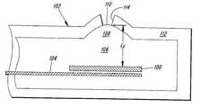
- FIG. 1is a cross-sectional view of a molded imager optical package in accordance with a preferred embodiment of the present invention.
- FIG. 5is a graph illustrating the relationship of focus position, signal-to-noise ratio and target illumination associated with certain embodiments of the present invention.
- FIG. 6is an exploded pictorial view of a hand held optical code imager embodiment of the present invention.
- FIG. 7is a cross-sectional view of a photo sensor optical assembly embodiment of the present invention.
- Embodiments of the present inventioninclude imaging code readers and cameras in which a solid state photo sensor with the capacity to detect an array of pixels, is encapsulated in a package. Portions of the package function as an objective lens, aperture and stabilizing medium for maintaining the proper separation between the semiconductor die or chip and the integrally molded lens to provide the desired (usually short) focal length for the system.
- a solid state photo sensor die 100is fabricated by conventional means (for example, using CMOS techniques) and encapsulated in package 102 .
- This photo sensormay have a one-dimensional line of cells for a linear bar code reader or may have cells in a two-dimensional area array suitable for imaging one-dimensional or two-dimensional optical codes or video images of objects or scenes.
- These devicesmay also include analog and/or digital signal processing circuitry for performing the additional functions required of a bar code scanner system or camera: exposure control, signal conditioning, digitizing, and decoding.
- the die 100may be mounted on a lead frame 104 , again using conventional means such as soldering and wire bonding or direct lead frame bonding to the die. Such mounting mechanically attaches and electrically connects the die to the lead frame.
- This assemblyis then placed into a mold cavity for injection molding of a first compound 106 .
- the first compoundis clear or has high light transmissivity for the wavelengths of interest. This material also may have a high index of refraction (>1) to enhance the optical power.
- the mold cavityhas a feature to position the lead frame 104 , and thus the die 100 , with respect to a lens or diffractive optical element (doe) molding feature of the mold cavity.
- FIG. 3illustrates a further embodiment of the present invention which includes the photo sensor die 100 , lead frame 104 , first transparent molded body 106 , focusing feature 108 , optical surface 110 and shell 112 with aperture 114 formed therein.
- a second die 300may also be mechanically and electrically attached to lead frame 104 .
- the second dieis an LED used for illumination or aiming.
- the first transparent molded bodyincludes a portion 302 which encases the die 300 and provides a second optical element (lens surface or doe) 304 for focusing light produced by the LED.
- the final assemblymay be further processed to form the lead frame for subsequent mounting in the final product, for example, for mounting to a circuit board.
- Off-the-shelf image detectors used in bar code readerstypically have large numbers of cells. Such readers use hardware digitizers to digitize the image signal in real time so that it does not have to be stored in memory. If fewer cells are used, they will collect more light and minimize the auxiliary illumination required. However, fewer cells introduce blur in the image which may not be tolerated by conventional hardware digitizers.
- the number of cells needed in the photo sensorcan be reduced to several hundred (of course, more cells can be used for increased range).
- One advantage of using a small number of cellsis that each cell receives more light from a fixed field of view compared to a system with a larger number of cells.
- Another advantageis that a photo sensor with fewer cells is simpler to build and lower cost. In addition the memory requirements of the system are reduced.
- F-numberis the conventional measure of relative aperture of the system.
- the F-numberis defined as: F ⁇ - ⁇ number ⁇ f D
- FIG. 4employs a photo sensor 400 with 512, 8 ⁇ m wide by 125 ⁇ m tall cells.
- An objective lens 402 and target bar code symbol 404are also shown.
- the image length L Iis about 4 mm.
- the focal length L Fis about 5 mm.
- a minimum package dimension L P of 6 mma lower bound on the physical volume of an engine with this detector is about 0.22 cm 3 , i.e., significantly less than one cubic centimeter.
- This engineis 50 times smaller than can be achieved with off-the-shelf CCD detectors which are used in conventional scanners.
- a 1000 cell (or larger) detectorcan be used with a small aperture and auxiliary illumination to achieve working ranges of 20 inches on 100% UPC.
- the small number of tall cells combined with a small F-numberpermits a system optimized for performance and miniaturization. Such a system can operate down to 1 lux of ambient light with no auxiliary illumination.
- L Ris estimated to be 3.1 inches with an estimated working range of 1.5 to 4.6 inches.
- L Ris estimated to be 4.3 inches with an estimated working range of 1.8 to 6.1 inches. This system has 0.7 inches of working range on 2 mil codes.
- System parametersare chosen such that the high blur digitizer provides adequate working range in minimal lighting conditions.
- the detector array parametersare based on an existing and proven solid state sensor design. Improvements to the minimum required ambient light can be made at the expense of working range and/or tolerance to rotational misalignment.
- a system with a medium blur digitizercan be designed by decreasing the aperture to match the performance of a system with the high blur digitizer.
- the high blur digitizerenables greater freedom in trading off range for minimum lighting requirements compared to a system with a medium blur digitizer.
- the one-dimensional imaging systemmay use a CMOS detector with 512 cells and an image length of 4 mm as noted above.
- the focus length required for a field of view of 40 degreesis about 5 mm.
- With a 1 mm wide by 3 mm high aperture the effective F-number of the systemis 2.6.
- the systemneeds a small fraction of the light ( ⁇ 0.015) compared to CCD-based systems to achieve similar signal-to-noise and can operate down to 0.4 fc ambient light, and therefore does not require auxiliary illumination.
- the He et al. digitizercontains three separate digitizers: low blur, medium blur and high blur.
- the low blur algorithmuses an adjustable thresholding scheme and requires about 80% modulation in the highest spatial frequency of the received signal.
- the medium blur algorithmuses a more complicated thresholding scheme and requires about 30% modulation in the highest frequency.
- the high blur digitizerrequires about 30% modulation in the second highest spatial frequency and infers the highest frequency edges from this information.
- Working range of a bar code readerdepends on a number of factors including bar code density, field of view and blur limits of the system. For example, using the above described system the calculated achievable working range for a bar code of 6.6 mil density is between 1.5 and 4.6 inches assuming digitization sufficient to tolerate a pixel per model ratio of less than one. It has been determined that a system with this working range could be implemented with a solid state detector with as few as 400 cells.
- the calculated signal-to-noise ratio of the above described one-dimensional photo sensor systemis presented in FIG. 5 as a function of target illumination for 6.6 mil symbols at the in-focus position (solid curve 600 ) and the out-of-focus limit (dashed curve 602 ).
- the detector arrayhas a cell height of 125 ⁇ m which corresponds to a detector footprint of 1 mm on the object at the in-focus position. If the detector array is misaligned with the bar code, then the blur due to cell averaging is increased.
- the imaging system proposed herecan tolerate up to 17 degrees rotation on 6.6 mil codes and 40 degrees rotation on 100% UPC. Working ranges for several rotation angles are given in the following Table II.
- Tolerance to rotational misalignmentcan be traded off for required ambient lighting by varying the cell height. Because cell size affects cell capacitance (and therefore conversion gain and kTC noise) the tradeoff of cell height must be analyzed in the context of the sensor electronics design.
- linear sensor-based code reading engines of the present inventionmay be implemented using the molded optical packages described in connection with FIGS. 1, 2 and 3 . Alternatively, such engines can be fashion illustrated in FIGS. 6 and 7.
- FIG. 6is an exploded pictorial view of a handheld optical code imager 700 , employing a solid state one-dimensional photo sensor 702 .
- the imager assemblyincludes housing halves 704 and 706 for containing a circuit board 708 to which the photo sensor 702 is attached and electrically connected.
- the circuit boardmay also carry solid state aiming or illumination devices such as LEDs or laser diodes 710 and 712 .
- the circuit board 708may be mechanically attached to housing front member 714 , for example, by fasteners 716 .
- Imager lens 718 and illumination or aiming lenses 720may be held in position in or against the housing front member 714 by housing face member 722 .
- Aperture 724admits the light sensed by the photo sensor 702 .
- Aiming or illumination lightexits the imager housing through apertures 726 .
- FIG. 7illustrates a further alternative structure for the photo sensor optical assembly.
- a solid state sensor die 800such as a linear array detector may be surface-mounted on a circuit board 802 .
- a glass cover slip 803protects the optically receptive surface of the die 800 .
- a molded transparent plastic cap 804includes an objective lens portion 806 .
- the system aperture 807may be defined by an opaque layer 808 on the lens surface 810 , or by the cylindrical sleeve portion 812 of the cap 804 .
- the cylindrical sleeve 812may be formed with attachment pins 814 which may be inserted into corresponding holes 816 in the circuit board 802 .
- the ends 818 of the pins 814may be heat-flaired to hold the cap in position with respect to the solid state sensor die 800 and, thus maintain the correct focal length for the system.
Landscapes
- Physics & Mathematics (AREA)
- Electromagnetism (AREA)
- Engineering & Computer Science (AREA)
- Health & Medical Sciences (AREA)
- General Health & Medical Sciences (AREA)
- Toxicology (AREA)
- Artificial Intelligence (AREA)
- Computer Vision & Pattern Recognition (AREA)
- General Physics & Mathematics (AREA)
- Theoretical Computer Science (AREA)
- Image Input (AREA)
- Solid State Image Pick-Up Elements (AREA)
Abstract
Description


| Field of | 40 | ||
| Focus distance | |||
| 3 inches (76.2 mm) | |||
| 4 mm | |||
| Focal length | 5.12 | ||
| Aperture size | |||
| 1 mm wide by 3 mm high | |||
| Number of | 512 | ||
| Cell width | 7.8 μm | ||
| Cell height | 125 μm | ||
| Quantum efficiency | .2 (a typical value for a CMOS | ||
| process) | |||
| Conversion gain | 3.2 μV/electron | ||
| Dark current | 19 mV/second | ||
| Saturation level | 800,000 electrons | ||
| Cell capacitance | 50 fF | ||
| KTC noise | 90 electrons rms @ 300 K | ||
| TABLE I | ||
| Range of ambient lighting (fc) | ||
| Bar code density | In-focus position | Out-of-focus limit |
| (mils) | Low | High* | High | ||
| 5 | .6 | 9000 | 5 | 9000 |
| 6.6 | .5 | 8100 | 5 | 9000 |
| 7.5 | .45 | 7700 | 5 | 9000 |
| 10 | .4 | 7000 | 5 | 9000 |
| 100% UPC | .4 | 6700 | 5 | 9000 |
| 20 | .4 | 6500 | 5 | 9000 |
| *This ambient light limitation can be increased by permitting integration times smaller than 1 ms. | ||||
| TABLE II | ||
| Working range (inches) | ||
| Density | 6.6 mil | 13 mil (100% UPC |
| Rotation angle (degrees) | Near | Far | Range | Near | Range | ||
| 0 | 1.5 | 4.6 | 3.1 | 1.8 | 6.1 | 4.3 |
| 5 | 1.5 | 4.4 | 2.9 | 1.8 | 5.9 | 4.1 |
| 10 | 1.6 | 3.9 | 2.3 | 1.8 | 5.5 | 3.7 |
| 15 | 1.9 | 3.2 | 1.3 | 1.8 | 4.8 | 3 |
| 17 | 2 | 2.8 | 0.8 | 1.8 | 4.6 | 2.8 |
| 20 | 1.8 | 4.3 | 2.5 | |||
| 25 | 1.8 | 3.8 | 2 | |||
| 30 | 1.8 | 3.3 | 1.5 | |||
| 35 | 1.8 | 2.9 | 1.1 | |||
| 40 | 1.8 | 2.5 | 0.7 | |||
Claims (15)
Priority Applications (1)
| Application Number | Priority Date | Filing Date | Title |
|---|---|---|---|
| US09/880,906US6685092B2 (en) | 2001-06-15 | 2001-06-15 | Molded imager optical package and miniaturized linear sensor-based code reading engines |
Applications Claiming Priority (1)
| Application Number | Priority Date | Filing Date | Title |
|---|---|---|---|
| US09/880,906US6685092B2 (en) | 2001-06-15 | 2001-06-15 | Molded imager optical package and miniaturized linear sensor-based code reading engines |
Publications (2)
| Publication Number | Publication Date |
|---|---|
| US20030024986A1 US20030024986A1 (en) | 2003-02-06 |
| US6685092B2true US6685092B2 (en) | 2004-02-03 |
Family
ID=25377369
Family Applications (1)
| Application Number | Title | Priority Date | Filing Date |
|---|---|---|---|
| US09/880,906Expired - LifetimeUS6685092B2 (en) | 2001-06-15 | 2001-06-15 | Molded imager optical package and miniaturized linear sensor-based code reading engines |
Country Status (1)
| Country | Link |
|---|---|
| US (1) | US6685092B2 (en) |
Cited By (17)
| Publication number | Priority date | Publication date | Assignee | Title |
|---|---|---|---|---|
| US20030141367A1 (en)* | 2002-01-11 | 2003-07-31 | Metrologic Instruments, Inc. | Modular omnidirectional bar code symbol scanning system with at least one service port for removable installation of a scan module insert |
| US20030189099A1 (en)* | 2002-04-09 | 2003-10-09 | Carlson Bradley S. | Semiconductor device adapted for imaging bar code symbols |
| US20070067981A1 (en)* | 2002-10-28 | 2007-03-29 | Joze Potocnik | Commutator for an electric machine and method for producing same |
| US20070080228A1 (en)* | 2000-11-24 | 2007-04-12 | Knowles C H | Compact bar code symbol reading system employing a complex of coplanar illumination and imaging stations for omni-directional imaging of objects within a 3D imaging volume |
| US20070119942A1 (en)* | 2005-11-29 | 2007-05-31 | Datalogic S.P.A. | Method, diaphragms and optical receiving devices for improving the depth of field in a linear optical code reader |
| US20070181689A1 (en)* | 2003-11-13 | 2007-08-09 | Metrologic Instruments, Inc. | Digital image capture and processing engine employing optical waveguide technology for collecting and guiding LED-based illumination during object illumination and image capture modes of operation |
| US7303126B2 (en) | 2004-03-18 | 2007-12-04 | Symbol Technologies, Inc. | System and method for sensing ambient light in an optical code reader |
| US20080006698A1 (en)* | 2003-11-13 | 2008-01-10 | Metrologic Instruments, Inc. | Method of and apparatus for dynamically and adaptively controlling system control parameters in a digital image capture and processing system |
| US20080048037A1 (en)* | 2006-08-22 | 2008-02-28 | Honeywell International Inc. | Low-cost compact bar code sensor |
| US20080121719A1 (en)* | 2000-11-24 | 2008-05-29 | Metrologic Instruments, Inc. | Digital imaging system employing the spectral-mixing of visible and invisible laser illumination during object imaging operations |
| US20080172303A1 (en)* | 2007-01-17 | 2008-07-17 | Ole-Petter Skaaksrud | Internet-based shipping, tracking and delivery network and system components supporting the capture of shipping document images and recognition-processing thereof initiated from the point of pickup and completed while shipment is being transported to its first scanning point in the network so as to increase velocity of shipping information through network and reduce delivery time |
| US20080277475A1 (en)* | 2003-11-13 | 2008-11-13 | Metrologic Instruments, Inc. | Digital image capture and processing system supporting a presentation mode of system operation which employs a combination of video and snapshot modes of image detection array operation during a single cycle of system operation |
| US7503498B2 (en) | 2003-11-13 | 2009-03-17 | Metrologic Instruments, Inc. | Hand-supportable digital image capturing and processing system employing an area-type image sensing array exposed to illumination from an LED-based illumination array only when all sensor elements in said image-sensing array are activated and in a state of integration |
| US20100303373A1 (en)* | 2009-05-28 | 2010-12-02 | Brian Keelan | System for enhancing depth of field with digital image processing |
| US9136258B1 (en)* | 2013-11-26 | 2015-09-15 | Maxim Integrated Products, Inc. | Stacked LED for optical sensor devices |
| US11700992B2 (en) | 2018-06-28 | 2023-07-18 | Boston Scientific Scimed, Inc. | Encapsulated components of medical devices, and methods therefor |
| US12440088B2 (en) | 2023-05-12 | 2025-10-14 | Boston Scientific Scimed, Inc. | Encapsulated components of medical devices, and methods therefor |
Families Citing this family (37)
| Publication number | Priority date | Publication date | Assignee | Title |
|---|---|---|---|---|
| US8788092B2 (en) | 2000-01-24 | 2014-07-22 | Irobot Corporation | Obstacle following sensor scheme for a mobile robot |
| US8412377B2 (en) | 2000-01-24 | 2013-04-02 | Irobot Corporation | Obstacle following sensor scheme for a mobile robot |
| US6956348B2 (en) | 2004-01-28 | 2005-10-18 | Irobot Corporation | Debris sensor for cleaning apparatus |
| US6690134B1 (en)* | 2001-01-24 | 2004-02-10 | Irobot Corporation | Method and system for robot localization and confinement |
| US7571511B2 (en) | 2002-01-03 | 2009-08-11 | Irobot Corporation | Autonomous floor-cleaning robot |
| US8396592B2 (en)* | 2001-06-12 | 2013-03-12 | Irobot Corporation | Method and system for multi-mode coverage for an autonomous robot |
| US7429843B2 (en)* | 2001-06-12 | 2008-09-30 | Irobot Corporation | Method and system for multi-mode coverage for an autonomous robot |
| US9128486B2 (en) | 2002-01-24 | 2015-09-08 | Irobot Corporation | Navigational control system for a robotic device |
| US8386081B2 (en) | 2002-09-13 | 2013-02-26 | Irobot Corporation | Navigational control system for a robotic device |
| US8428778B2 (en) | 2002-09-13 | 2013-04-23 | Irobot Corporation | Navigational control system for a robotic device |
| KR100539234B1 (en)* | 2003-06-11 | 2005-12-27 | 삼성전자주식회사 | A CMOS type image sensor module having transparent polymeric encapsulation material |
| US7332890B2 (en)* | 2004-01-21 | 2008-02-19 | Irobot Corporation | Autonomous robot auto-docking and energy management systems and methods |
| US7535071B2 (en)* | 2004-03-29 | 2009-05-19 | Evolution Robotics, Inc. | System and method of integrating optics into an IC package |
| SG174000A1 (en) | 2004-06-24 | 2011-09-29 | Irobot Corp | Remote control scheduler and method for autonomous robotic device |
| US7706917B1 (en) | 2004-07-07 | 2010-04-27 | Irobot Corporation | Celestial navigation system for an autonomous robot |
| US8972052B2 (en) | 2004-07-07 | 2015-03-03 | Irobot Corporation | Celestial navigation system for an autonomous vehicle |
| US8392021B2 (en) | 2005-02-18 | 2013-03-05 | Irobot Corporation | Autonomous surface cleaning robot for wet cleaning |
| KR101240732B1 (en)* | 2005-02-18 | 2013-03-07 | 아이로보트 코퍼레이션 | Autonomous surface cleaning robot for wet and dry cleaning |
| US7620476B2 (en) | 2005-02-18 | 2009-11-17 | Irobot Corporation | Autonomous surface cleaning robot for dry cleaning |
| US8930023B2 (en) | 2009-11-06 | 2015-01-06 | Irobot Corporation | Localization by learning of wave-signal distributions |
| US20070097250A1 (en)* | 2005-10-27 | 2007-05-03 | Spears Kurt E | Imaging system and method |
| KR101099808B1 (en)* | 2005-12-02 | 2011-12-27 | 아이로보트 코퍼레이션 | Robotic systems |
| EP2270619B1 (en)* | 2005-12-02 | 2013-05-08 | iRobot Corporation | Modular robot |
| US9144360B2 (en) | 2005-12-02 | 2015-09-29 | Irobot Corporation | Autonomous coverage robot navigation system |
| EP2816434A3 (en) | 2005-12-02 | 2015-01-28 | iRobot Corporation | Autonomous coverage robot |
| KR101300492B1 (en)* | 2005-12-02 | 2013-09-02 | 아이로보트 코퍼레이션 | Coverage robot mobility |
| US20090044370A1 (en) | 2006-05-19 | 2009-02-19 | Irobot Corporation | Removing debris from cleaning robots |
| US8417383B2 (en) | 2006-05-31 | 2013-04-09 | Irobot Corporation | Detecting robot stasis |
| US20080023555A1 (en)* | 2006-07-31 | 2008-01-31 | Edward Barkan | Aperture stop in imaging reader |
| ES2571739T3 (en) | 2007-05-09 | 2016-05-26 | Irobot Corp | Autonomous compact covering robot |
| JP5027735B2 (en)* | 2007-05-25 | 2012-09-19 | サッポロビール株式会社 | Method for producing sparkling alcoholic beverage |
| WO2011103198A1 (en) | 2010-02-16 | 2011-08-25 | Irobot Corporation | Vacuum brush |
| US9697331B2 (en)* | 2011-11-01 | 2017-07-04 | Codonics, Inc. | Adaptable information extraction and labeling method and system |
| US20130105568A1 (en)* | 2011-11-01 | 2013-05-02 | Codonics, Inc. | Adaptable information extraction and labeling method and system |
| US9280693B2 (en)* | 2014-05-13 | 2016-03-08 | Hand Held Products, Inc. | Indicia-reader housing with an integrated optical structure |
| US20170288067A1 (en)* | 2016-03-30 | 2017-10-05 | Intel Corporation | Optical sensor shield |
| US11953722B2 (en)* | 2021-06-02 | 2024-04-09 | Luminar Technologies, Inc. | Protective mask for an optical receiver |
Citations (15)
| Publication number | Priority date | Publication date | Assignee | Title |
|---|---|---|---|---|
| US4743955A (en)* | 1985-05-01 | 1988-05-10 | Canon Kabushiki Kaisha | Photoelectric converting device |
| US5444230A (en)* | 1993-11-30 | 1995-08-22 | Minnesota Mining And Manufacturing Company | Solid state optical reader with bi-directional protocol |
| US5495097A (en)* | 1993-09-14 | 1996-02-27 | Symbol Technologies, Inc. | Plurality of scan units with scan stitching |
| US5596446A (en)* | 1990-11-15 | 1997-01-21 | Gap Technologies, Inc. | Ultra compact scanning system for a wide range of speeds, angles and field depth |
| US5703349A (en) | 1995-06-26 | 1997-12-30 | Metanetics Corporation | Portable data collection device with two dimensional imaging assembly |
| US5724401A (en)* | 1996-01-24 | 1998-03-03 | The Penn State Research Foundation | Large angle solid state position sensitive x-ray detector system |
| US5814803A (en)* | 1994-12-23 | 1998-09-29 | Spectra-Physics Scanning Systems, Inc. | Image reader with multi-focus lens |
| US5864128A (en)* | 1991-10-15 | 1999-01-26 | Geo Labs, Inc. | Lens with variable focal length |
| US5925867A (en)* | 1996-09-27 | 1999-07-20 | Oki Electric Industry Co., Ltd. | Optical device including multiple reflectors and optical systems for reading bar codes |
| US6138915A (en)* | 1986-08-08 | 2000-10-31 | Intermec Ip Corp. | Hand-held optically readable character set reader having automatic focus control for operation over a range of distances |
| US6347744B1 (en)* | 1995-10-10 | 2002-02-19 | Symbol Technologies, Inc. | Retroreflective scan module for electro-optical readers |
| US6351288B1 (en)* | 1997-06-27 | 2002-02-26 | Eastman Kodak Company | Sensor tilt control for a digital camera |
| US6375076B1 (en)* | 1997-04-21 | 2002-04-23 | Intermec Ip Corp. | Optoelectronic device for acquisition of images, in particular of bar codes |
| US6431452B2 (en)* | 1997-01-31 | 2002-08-13 | Metanetics Corporation | Portable data collection device with variable focusing module for optic assembly |
| US6435411B1 (en)* | 1997-04-21 | 2002-08-20 | Intermec Ip Corp. | Optoelectronic device for acquisition of images, in particular of bar codes |
- 2001
- 2001-06-15USUS09/880,906patent/US6685092B2/ennot_activeExpired - Lifetime
Patent Citations (16)
| Publication number | Priority date | Publication date | Assignee | Title |
|---|---|---|---|---|
| US4743955A (en)* | 1985-05-01 | 1988-05-10 | Canon Kabushiki Kaisha | Photoelectric converting device |
| US6138915A (en)* | 1986-08-08 | 2000-10-31 | Intermec Ip Corp. | Hand-held optically readable character set reader having automatic focus control for operation over a range of distances |
| US5596446A (en)* | 1990-11-15 | 1997-01-21 | Gap Technologies, Inc. | Ultra compact scanning system for a wide range of speeds, angles and field depth |
| US5864128A (en)* | 1991-10-15 | 1999-01-26 | Geo Labs, Inc. | Lens with variable focal length |
| US5495097A (en)* | 1993-09-14 | 1996-02-27 | Symbol Technologies, Inc. | Plurality of scan units with scan stitching |
| US5444230A (en)* | 1993-11-30 | 1995-08-22 | Minnesota Mining And Manufacturing Company | Solid state optical reader with bi-directional protocol |
| US5814803A (en)* | 1994-12-23 | 1998-09-29 | Spectra-Physics Scanning Systems, Inc. | Image reader with multi-focus lens |
| US6073851A (en)* | 1994-12-23 | 2000-06-13 | Spectra-Physics Scanning Systems, Inc. | Multi-focus optical reader with masked or apodized lens |
| US5703349A (en) | 1995-06-26 | 1997-12-30 | Metanetics Corporation | Portable data collection device with two dimensional imaging assembly |
| US6347744B1 (en)* | 1995-10-10 | 2002-02-19 | Symbol Technologies, Inc. | Retroreflective scan module for electro-optical readers |
| US5724401A (en)* | 1996-01-24 | 1998-03-03 | The Penn State Research Foundation | Large angle solid state position sensitive x-ray detector system |
| US5925867A (en)* | 1996-09-27 | 1999-07-20 | Oki Electric Industry Co., Ltd. | Optical device including multiple reflectors and optical systems for reading bar codes |
| US6431452B2 (en)* | 1997-01-31 | 2002-08-13 | Metanetics Corporation | Portable data collection device with variable focusing module for optic assembly |
| US6375076B1 (en)* | 1997-04-21 | 2002-04-23 | Intermec Ip Corp. | Optoelectronic device for acquisition of images, in particular of bar codes |
| US6435411B1 (en)* | 1997-04-21 | 2002-08-20 | Intermec Ip Corp. | Optoelectronic device for acquisition of images, in particular of bar codes |
| US6351288B1 (en)* | 1997-06-27 | 2002-02-26 | Eastman Kodak Company | Sensor tilt control for a digital camera |
Cited By (155)
| Publication number | Priority date | Publication date | Assignee | Title |
|---|---|---|---|---|
| US7533820B2 (en) | 2000-11-24 | 2009-05-19 | Metrologic Instruments, Inc. | Digital image capturing and processing system employing coplanar illumination and imaging stations which generate coplanar illumination and imaging planes only when and where an object is being moved within the 3D imaging volume |
| US7793841B2 (en) | 2000-11-24 | 2010-09-14 | Metrologic Instruments, Inc. | Laser illumination beam generation system employing despeckling of the laser beam using high-frequency modulation of the laser diode current and optical multiplexing of the component laser beams |
| US8172141B2 (en) | 2000-11-24 | 2012-05-08 | Metrologic Instruments, Inc. | Laser beam despeckling devices |
| US8042740B2 (en) | 2000-11-24 | 2011-10-25 | Metrologic Instruments, Inc. | Method of reading bar code symbols on objects at a point-of-sale station by passing said objects through a complex of stationary coplanar illumination and imaging planes projected into a 3D imaging volume |
| US7905413B2 (en) | 2000-11-24 | 2011-03-15 | Metrologic Instruments, Inc. | Digital image capturing and processing system employing a plurality of coplanar illumination and imaging subsystems for digitally imaging objects in a 3D imaging volume, and a globally-deployed object motion detection subsystem for automatically detecting and analyzing the motion of objects passing through said 3-D imaging volume |
| US7878407B2 (en) | 2000-11-24 | 2011-02-01 | Metrologic Instruments, Inc. | POS-based digital image capturing and processing system employing automatic object motion detection and spectral-mixing based illumination techniques |
| US7806335B2 (en) | 2000-11-24 | 2010-10-05 | Metrologic Instruments, Inc. | Digital image capturing and processing system for automatically recognizing objects in a POS environment |
| US20070080228A1 (en)* | 2000-11-24 | 2007-04-12 | Knowles C H | Compact bar code symbol reading system employing a complex of coplanar illumination and imaging stations for omni-directional imaging of objects within a 3D imaging volume |
| US7806336B2 (en) | 2000-11-24 | 2010-10-05 | Metrologic Instruments, Inc. | Laser beam generation system employing a laser diode and high-frequency modulation circuitry mounted on a flexible circuit |
| US7784695B2 (en) | 2000-11-24 | 2010-08-31 | Metrologic Instruments, Inc. | Planar laser illumination module (PLIM) employing high-frequency modulation (HFM) of the laser drive currents and optical multplexing of the output laser beams |
| US7775436B2 (en) | 2000-11-24 | 2010-08-17 | Metrologic Instruments, Inc. | Method of driving a plurality of visible and invisible LEDs so as to produce an illumination beam having a dynamically managed ratio of visible to invisible (IR) spectral energy/power during object illumination and imaging operations |
| US7770796B2 (en) | 2000-11-24 | 2010-08-10 | Metrologic Instruments, Inc. | Device for producing a laser beam of reduced coherency using high-frequency modulation of the laser diode current and optical multiplexing of the output laser beam |
| US20070210166A1 (en)* | 2000-11-24 | 2007-09-13 | Knowles C H | Omni-directional digital image capturing and processing system comprising coplanar illumination and imaging stations automatically detecting object motion and velocity and adjusting exposure and/or illumination control parameters therewithin |
| US20070210167A1 (en)* | 2000-11-24 | 2007-09-13 | Knowles C H | Digital image capturing and processing system having a plurality of coplanar illumination and imaging subsystems, each employing a dual-type coplanar linear illumination and imaging engine that supports image-processing based object motion and velocity detection, and automatic image formation and detection along the coplanar illumination and imaging plane produced thereby |
| US20070210170A1 (en)* | 2000-11-24 | 2007-09-13 | Metrologic Instruments, Inc. | Digital-imaging based code symbol reading system employing a plurality of coplanar illumination and imaging subsystems, global object motion detection subsystem for automatic detecting objects within its 3D imaging volume, and global control subsystem for managing the state of operation of said coplanar illumination and imaging subsystems |
| US20070210165A1 (en)* | 2000-11-24 | 2007-09-13 | Metrologic Instruments, Inc. | Digital image capturing and processing system employing coplanar illumination and imaging stations which generate coplanar illumination and imaging planes only when and where an object is being moved within the 3D imaging volume |
| US20070210168A1 (en)* | 2000-11-24 | 2007-09-13 | Knowles C H | Omni-directional digital image capturing and processing system employing coplanar illumination and imaging stations in horizontal and vertical housing sections of the system |
| US20070241193A1 (en)* | 2000-11-24 | 2007-10-18 | Knowles C H | Digital image capturing and processing system employing imaging window protection plate having an aperture pattern and being disposed over said imaging window and beneath which resides a plurality of coplanar illumination and imaging stations |
| US20070257114A1 (en)* | 2000-11-24 | 2007-11-08 | Knowles C H | Automatic omnidirectional bar code symbol reading system employing linear-type and area-type bar code symbol reading stations within the system housing |
| US20070257115A1 (en)* | 2000-11-24 | 2007-11-08 | Knowles C H | Method for intelligently controlling the illumination and imagine of objects as they are moved through the 3D imaging volume of a digital image capturing and processing system |
| US20070262149A1 (en)* | 2000-11-24 | 2007-11-15 | Knowles C H | Method of and apparatus for identifying consumer products in a retail environment when bar code symbols on the products are not readable or have been removed from packaging |
| US20070262153A1 (en)* | 2000-11-24 | 2007-11-15 | Knowles C H | Digital image capturing and processing system for producing and projecting a complex of coplanar illumination and imaging planes into a 3D imaging volume and controlling illumination control parameters in said system using the detected motion and velocity of objects present therewithin |
| US20070262150A1 (en)* | 2000-11-24 | 2007-11-15 | Knowles C H | Digital image capturing and processing system employing a plurality of coplanar illuminating and imaging stations projecting a plurality of coplanar illumination and imaging planes into a 3D imaging volume, and controlling operations therewithin using control data derived from motion data collected from the automated detection of objects passing through said 3D imaging volume |
| US7762465B2 (en) | 2000-11-24 | 2010-07-27 | Metrologic Instruments, Inc. | Device for optically multiplexing a laser beam |
| US7533823B2 (en) | 2000-11-24 | 2009-05-19 | Metrologic Instruments, Inc. | Digital image capturing and processing system employing a plurality of coplanar illuminating and imaging stations projecting a plurality of coplanar illumination and imaging planes into a 3D imaging volume, and controlling operations therewithin using control data derived from motion data collected from the automated detection of objects passing through said 3D imaging volume |
| US20070278308A1 (en)* | 2000-11-24 | 2007-12-06 | Metrologic Instruments, Inc. | Digital image capturing and processing system employing a plurality of coplanar illumination and imaging subsystems for digitally imaging objects in a 3D imaging volume, and a globally-deployed object motion detection subsystem for automatically detecting and analyzing the motion of object passing through said 3D imaging volume |
| US20080000983A1 (en)* | 2000-11-24 | 2008-01-03 | Knowles C H | Automatic POS-based digital image capturing and processing system employing object motion controlled area-type illumination and imaging operations |
| US20080000982A1 (en)* | 2000-11-24 | 2008-01-03 | Knowles C H | Automatic POS-based digital image capturing and processing system employing object motion controlled area-type illumination and imaging operations |
| US7731091B2 (en) | 2000-11-24 | 2010-06-08 | Metrologic Instruments, Inc. | Digital image capturing and processing system employing automatic object detection and spectral-mixing based illumination techniques |
| US20080017716A1 (en)* | 2000-11-24 | 2008-01-24 | Knowles C H | Automatic pos-based digital image capturing and processing system employing a plurality of area-type illumination and imaging zones intersecting within the 3D imaging volume of the system |
| US20080017715A1 (en)* | 2000-11-24 | 2008-01-24 | Metrologic Instruments, Inc. | Automatic pos-based digital image capturing and processing system employing a plurality of area-type illumination and imaging zones intersecting within the 3D imaging volume of the system |
| US20080023559A1 (en)* | 2000-11-24 | 2008-01-31 | Knowles C H | Omni-directional digital image capturing and processing system employing coplanar illumination and imaging planes and area-type illumination and imaging zones within the system housing |
| US20080029600A1 (en)* | 2000-11-24 | 2008-02-07 | Metrologic Instruments, Inc. | Digital-imaging based code symbol reading system employing a plurality of coplanar illumination and imaging subsystems, each having a local object motion detection subsystem for automatic detecting objects within the 3D imaging volume, and a local control subsystem for transmitting object detection state data to a global control subsystem for managing the state of operation of said coplanar illumination and imaging subsystems |
| US20080029605A1 (en)* | 2000-11-24 | 2008-02-07 | Knowles C H | Automatic omnidirectional bar code symbol reading system employing linear-type and area-type bar code symbol reading stations within the system housing |
| US20080041959A1 (en)* | 2000-11-24 | 2008-02-21 | Knowles C H | Digital image capturing and processing system employing a plurality of area-type illuminating and imaging stations projecting a plurality of coextensive area-type illumination and imaging zones into a 3D imaging volume, and controlling operations therewithin using control data derived from velocity data collected from the automated detection of objects passing through said 3D imaging volume |
| US20080041958A1 (en)* | 2000-11-24 | 2008-02-21 | Metrologic Instruments, Inc. | Digital image capturing and processing system for producing and projecting a plurality of coextensive area-type illumination and imaging zones into a 3D imaging volume and controlling illumination control parameters in said system using the detected motion of objects present therewithin |
| US7673802B2 (en) | 2000-11-24 | 2010-03-09 | Metrologic Instruments, Inc. | Automatic POS-based digital image capturing and processing system employing a plurality of area-type illumination and imaging zones intersecting within the 3D imaging volume of the system |
| US20080121719A1 (en)* | 2000-11-24 | 2008-05-29 | Metrologic Instruments, Inc. | Digital imaging system employing the spectral-mixing of visible and invisible laser illumination during object imaging operations |
| US7665665B2 (en) | 2000-11-24 | 2010-02-23 | Metrologic Instruments, Inc. | Digital illumination and imaging subsystem employing despeckling mechanism employing high-frequency modulation of laser diode drive current and optical beam multiplexing techniques |
| US20080128510A1 (en)* | 2000-11-24 | 2008-06-05 | Knowles C Harry | Laser beam generation system employing a laser diode and high-frequency modulation circuitry mounted on a flexible circuit |
| US20080135622A1 (en)* | 2000-11-24 | 2008-06-12 | Knowles C Harry | Planar laser illumination module (PLIM) employing high-frequency modulation (HFM) of the laser drive currents and optical multplexing of the output laser beams |
| US20080142601A1 (en)* | 2000-11-24 | 2008-06-19 | Knowles C Harry | Device for optically multiplexing a laser beam |
| US20080149726A1 (en)* | 2000-11-24 | 2008-06-26 | Metrologic Instruments, Inc. | Laser beam despeckling devices |
| US20080156877A1 (en)* | 2000-11-24 | 2008-07-03 | Metrologic Instruments, Inc. | Device for producing a laser beam of reduced coherency using high-frequency modulation of the laser diode current and optical multiplexing of the output laser beam |
| US20080169348A1 (en)* | 2000-11-24 | 2008-07-17 | Metrologic Instruments, Inc. | Method of illuminating objects during digital image capture operations by mixing visible and invisible spectral illumination energy at poing of sale (POS) environments |
| US7661597B2 (en) | 2000-11-24 | 2010-02-16 | Metrologic Instruments, Inc. | Coplanar laser illumination and imaging subsystem employing spectral-mixing and despeckling of laser illumination |
| US7661595B2 (en) | 2000-11-24 | 2010-02-16 | Metrologic Instruments, Inc. | Digital image capturing and processing system employing a plurality of area-type illuminating and imaging stations projecting a plurality of coextensive area-type illumination and imaging zones into a 3D imaging volume, and controlling operations therewithin using |
| US7658330B2 (en) | 2000-11-24 | 2010-02-09 | Metrologic Instruments, Inc. | Automatic POS-based digital image capturing and processing system employing object motion controlled area-type illumination and imaging operations |
| US7614560B2 (en) | 2000-11-24 | 2009-11-10 | Metrologic Instruments, Inc. | Method of illuminating objects at a point of sale (POS) station by adaptively controlling the spectral composition of the wide-area illumination beam produced from an illumination subsystem within an automatic digital image capture and processing system |
| US7611062B2 (en) | 2000-11-24 | 2009-11-03 | Metrologic Instruments, Inc. | Omni-directional digital image capturing and processing system employing coplanar illumination and imaging planes and area-type illumination and imaging zones with the horizontal and vertical sections of the system housing |
| US20080185439A1 (en)* | 2000-11-24 | 2008-08-07 | Metrologic Instruments, Inc. | Digital illumination and imaging subsystem employing despeckling mechanism employing high-frequency modulation of laser diode drive current and optical beam multiplexing techniques |
| US7594608B2 (en) | 2000-11-24 | 2009-09-29 | Metrologic Instruments, Inc. | Automatic omnidirectional bar code symbol reading system employing linear-type and area-type bar code symbol reading stations within the system housing |
| US7588188B2 (en) | 2000-11-24 | 2009-09-15 | Metrologic Instruments, Inc. | Pos-based digital image capturing and processing system using automatic object detection, spectral-mixing based illumination and linear imaging techniques |
| US7584892B2 (en) | 2000-11-24 | 2009-09-08 | Metrologic Instruments, Inc. | Digital-imaging based code symbol reading system employing a plurality of coplanar illumination and imaging subsystems, each having a local object motion detection subsystem for automatic detecting objects within the 3D imaging volume, and a local control subsystem for transmitting object detection state data to a global control subsystem for managing the state of operation of said coplanar illumination and imaging subsystems |
| US7581680B2 (en) | 2000-11-24 | 2009-09-01 | Metrologic Instruments, Inc. | Omni-directional digital image capturing and processing system employing coplanar illumination and imaging stations in horizontal and vertical housing sections of the system |
| US20080249884A1 (en)* | 2000-11-24 | 2008-10-09 | Metrologic Instruments, Inc. | POS-centric digital imaging system |
| US7578445B2 (en) | 2000-11-24 | 2009-08-25 | Metrologic Instruments, Inc. | Automatic POS-based digital image capturing and processing system employing object motion controlled area-type illumination and imaging operations |
| US7578442B2 (en) | 2000-11-24 | 2009-08-25 | Metrologic Instruments, Inc. | Method of and apparatus for identifying consumer products in a retail environment when bar code symbols on the products are not readable or have been removed from packaging |
| US7575169B2 (en) | 2000-11-24 | 2009-08-18 | Metrologic Instruments, Inc. | Digital image capturing and processing system for producing and projecting a plurality of coextensive area-type illumination and imaging zones into a 3D imaging volume and controlling illumination control parameters in said system using the detected motion of objects present therewithin |
| US7575170B2 (en) | 2000-11-24 | 2009-08-18 | Metrologic Instruments, Inc. | POS-based digital image capturing and processing system using automatic object detection, spectral-mixing based illumination and linear imaging techniques |
| US7571859B2 (en) | 2000-11-24 | 2009-08-11 | Metrologic Instruments, Inc. | Digital-imaging based code symbol reading system employing a plurality of coplanar illumination and imaging subsystems, global object motion detection subsystem for automatically detecting objects within its 3D imaging volume, and global control subsystem for managing the state of operation of said coplanar illumination and imaging substems |
| US7571858B2 (en) | 2000-11-24 | 2009-08-11 | Metrologic Instruemtns, Inc. | POS-based digital image capturing and processing system using automatic object detection, spectral-mixing based illumination and linear imaging techniques |
| US20080283611A1 (en)* | 2000-11-24 | 2008-11-20 | Metrologic Instruments, Inc. | Digital image capture and processing systems for supporting 3D imaging volumes in retail point-of-sale environments |
| US7568626B2 (en) | 2000-11-24 | 2009-08-04 | Metrologic Instruments, Inc. | Automatic POS-based digital image capturing and processing system employing a plurality of area-type illumination and imaging zones intersecting within the 3D imaging volume of the system |
| US7559474B2 (en) | 2000-11-24 | 2009-07-14 | Metrologic Instruments, Inc. | Automatic omnidirectional bar code symbol reading system employing linear-type and area-type bar code symbol reading stations within the system housing |
| US7556199B2 (en) | 2000-11-24 | 2009-07-07 | Metrologic Instruments, Inc. | Digital image capturing and processing system employing a plurality of coplanar illuminating and imaging stations projecting a complex of coplanar illumination and imaging planes into a 3D imaging volume so as to support pass-through and presentation modes of digital imaging at a point of sale (POS) environment |
| US7546952B2 (en) | 2000-11-24 | 2009-06-16 | Metrologic Instruments, Inc. | Method of illuminating objects during digital image capture operations by mixing visible and invisible spectral illumination energy at point of sale (POS) environments |
| US7543749B2 (en) | 2000-11-24 | 2009-06-09 | Metrologic Instruments, Inc. | Digital image capturing and processing system having a plurality of coplanar illumination and imaging subsystems, each employing a dual-type coplanar linear illumination and imaging engine that supports image-processing based object motion and velocity detection, and automatic image formation and detection along the coplanar illumination and imaging plane produced thereby |
| US7537165B2 (en) | 2000-11-24 | 2009-05-26 | Metrologic Instruments, Inc. | Omni-directional digital image capturing and processing system employing coplanar illumination and imaging planes and area-type illumination and imaging zones within the system housing |
| US7540422B2 (en) | 2000-11-24 | 2009-06-02 | Metrologic Instruments, Inc. | Digital image capturing and processing system employing imaging window protection plate having an aperture pattern and being disposed over said imaging window and beneath which resides a plurality of coplanar illumination and imaging stations |
| US20090065584A1 (en)* | 2000-11-24 | 2009-03-12 | Metrologic Instruments, Inc. | Pos-based digital image capturing and processing system employing automatic object motion detection and spectral-mixing based illumination techniques |
| US7540424B2 (en) | 2000-11-24 | 2009-06-02 | Metrologic Instruments, Inc. | Compact bar code symbol reading system employing a complex of coplanar illumination and imaging stations for omni-directional imaging of objects within a 3D imaging volume |
| US7516898B2 (en) | 2000-11-24 | 2009-04-14 | Metrologic Instruments, Inc. | Digital image capturing and processing system for producing and projecting a complex of coplanar illumination and imaging planes into a 3D imaging volume and controlling illumination control parameters in said system using the detected motion and velocity of object |
| US7520433B2 (en) | 2000-11-24 | 2009-04-21 | Metrologic Instruments, Inc. | Method for intelligently controlling the illumination and imagine of objects as they are moved through the 3D imaging volume of a digital image capturing and processing system |
| US20090101718A1 (en)* | 2000-11-24 | 2009-04-23 | Metrologic Instruments, Inc. | Digital image capturing and processing system employing automatic object detection and spectral-mixing based illumination techniques |
| US7527204B2 (en) | 2000-11-24 | 2009-05-05 | Metrologic Instruments, Inc. | Omni-directional digital image capturing and processing system comprising coplanar illumination and imaging stations automatically detecting object motion and velocity and adjusting exposure and/or illumination control parameters therewithin |
| US20070278309A1 (en)* | 2000-11-24 | 2007-12-06 | Metrologic Instruments, Inc. | Digital image capturing and processing system employing a plurality of coplanar illuminating and imaging stations projecting a complex of coplanar illumination and imaging planes into a 3D imaging volume so as to support pass-through and presentation modes of digital imaging at a point of sale (POS) environment |
| US6874690B2 (en) | 2002-01-11 | 2005-04-05 | Metrologic Instruments, Inc. | Modular omnidirectional bar code symbol scanning system with at least one service port for removable installation of scan module insert |
| US20050103852A1 (en)* | 2002-01-11 | 2005-05-19 | Metrologic Instruments, Inc. | Modular omnidirectional bar code symbol scanning system with at least one service port for removable installation of scan module insert |
| US7195167B2 (en) | 2002-01-11 | 2007-03-27 | Metrologic Instruments, Inc. | Modular omnidirectional bar code symbol scanning system with at least one service port for removable installation of scan module insert |
| US20030141367A1 (en)* | 2002-01-11 | 2003-07-31 | Metrologic Instruments, Inc. | Modular omnidirectional bar code symbol scanning system with at least one service port for removable installation of a scan module insert |
| US20030189099A1 (en)* | 2002-04-09 | 2003-10-09 | Carlson Bradley S. | Semiconductor device adapted for imaging bar code symbols |
| US6837431B2 (en)* | 2002-04-09 | 2005-01-04 | Symbol Technologies, Inc. | Semiconductor device adapted for imaging bar code symbols |
| US20070067981A1 (en)* | 2002-10-28 | 2007-03-29 | Joze Potocnik | Commutator for an electric machine and method for producing same |
| US7922089B2 (en) | 2003-11-13 | 2011-04-12 | Metrologic Instruments, Inc. | Hand-supportable digital image capture and processing system employing automatic object presence detection to control automatic generation of a linear targeting illumination beam within the field of view (FOV), and manual trigger switching to initiate illumination |
| US7980471B2 (en) | 2003-11-13 | 2011-07-19 | Metrologic Instruments, Inc. | Method of unlocking restricted extended classes of features and functionalities embodied within a digital image capture and processing system by reading feature/functionality-unlocking type code symbols |
| US20080290172A1 (en)* | 2003-11-13 | 2008-11-27 | Metrologic Instruments, Inc. | Hand-supportable digital image capture and processing system employing manual trigger switching to control generation of a linear targeting illumination beam within the field of view (FOV), and to initiate illumination of the detected object and the capturing and processing of digital images thereof |
| US20080283607A1 (en)* | 2003-11-13 | 2008-11-20 | Metrologic Instruments, Inc. | Hand-supportable digital image capture and processing system employing visible targeting illumination beam projected from an array of visible light sources on the rear surface of a printed circuit (PC) board having a light transmission aperture, and reflected off multiple folding mirrors and projected through the light transmission aperture into a central portion of the field of view of said system |
| US20080283606A1 (en)* | 2003-11-13 | 2008-11-20 | Anatoly Kotlarsky | Digital image capture and processing system supporting a periodic snapshot mode of operation wherein during each image acquistion cycle, the rows of image detection elements in the image detection array are exposed simultaneously to illumination |
| US9104930B2 (en) | 2003-11-13 | 2015-08-11 | Metrologic Instruments, Inc. | Code symbol reading system |
| US20080277479A1 (en)* | 2003-11-13 | 2008-11-13 | Metrologic Instruments, Inc. | Countertop-based digital image capture and processing system having an illumination subsystem employing a single array of LEDS disposed behind an illumination focusing lens structure integrated within the imaging window, for generating a field of visible illumination highly confined below the field of view of the system operator and customers who are present during object illumination and imaging operations |
| US20080277476A1 (en)* | 2003-11-13 | 2008-11-13 | Anatoly Kotlarsky | Method of blocking a portion of illumination rays generated by a countertop-supported digital imaging system, and preventing illumination rays from striking the eyes of the system operator or nearby consumer during operation of said countertop-supported digital image capture and processing system installed at a retail point of sale (POS) station |
| US20080277473A1 (en)* | 2003-11-13 | 2008-11-13 | Metrologic Intruments, Inc. | Digital image capture and processing system employing an image formation and detection system having an area-type image detection array supporting single snap-shot and periodic snap-shot modes of image acquisition during object illumination and imaging operations |
| US20080277475A1 (en)* | 2003-11-13 | 2008-11-13 | Metrologic Instruments, Inc. | Digital image capture and processing system supporting a presentation mode of system operation which employs a combination of video and snapshot modes of image detection array operation during a single cycle of system operation |
| US8317105B2 (en) | 2003-11-13 | 2012-11-27 | Metrologic Instruments, Inc. | Optical scanning system having an extended programming mode and method of unlocking restricted extended classes of features and functionalities embodied therewithin |
| US20090020610A1 (en)* | 2003-11-13 | 2009-01-22 | Metrologic Instruments, Inc. | Digital image capture and processing system employing an image formation and detection subsystem having an area-type image detection array supporting periodic occurrance of snap-shot type image acquisition cycles at a high-repetition rate during object illumination and imaging operations |
| US8157174B2 (en) | 2003-11-13 | 2012-04-17 | Metrologic Instruments, Inc. | Digital image capture and processing system employing an image formation and detection system having an area-type image detection array supporting single snap-shot and periodic snap-shot modes of image acquisition during object illumination and imaging operations |
| US7594609B2 (en) | 2003-11-13 | 2009-09-29 | Metrologic Instruments, Inc. | Automatic digital video image capture and processing system supporting image-processing based code symbol reading during a pass-through mode of system operation at a retail point of sale (POS) station |
| US8157175B2 (en) | 2003-11-13 | 2012-04-17 | Metrologic Instruments, Inc. | Digital image capture and processing system supporting a presentation mode of system operation which employs a combination of video and snapshot modes of image detection array operation during a single cycle of system operation |
| US8132731B2 (en) | 2003-11-13 | 2012-03-13 | Metrologic Instruments, Inc. | Digital image capture and processing system having a printed circuit (PC) board with a light transmission aperture, wherein an image detection array is mounted on the rear side of said PC board, and a linear array of light emitting diodes (LEDS) is mounted on the front surface of said PC board, and aligned with an illumination-focusing lens structure integrated within said imaging window |
| US8100331B2 (en) | 2003-11-13 | 2012-01-24 | Metrologic Instruments, Inc. | Digital image capture and processing system having a printed circuit (PC) board with light transmission aperture, wherein first and second field of view (FOV) folding mirrors project the FOV of a digital image detection array on the rear surface of said PC board, through said light transmission aperture |
| US8087588B2 (en) | 2003-11-13 | 2012-01-03 | Metrologic Instruments, Inc. | Digital image capture and processing system having a single printed circuit (PC) board with a light transmission aperture, wherein a first linear array of visible light emitting diodes (LEDs) are mounted on the rear side of the PC board for producing a linear targeting illumination beam, and wherein a second linear array of visible LEDs are mounted on the front side of said PC board for producing a field of visible illumination within the field of view (FOV) of the system |
| US8052057B2 (en) | 2003-11-13 | 2011-11-08 | Metrologic Instruments, Inc. | Method of programming the system configuration parameters of a digital image capture and processing system during the implementation of its communication interface with a host system without reading programming-type bar code symbols |
| US8047438B2 (en) | 2003-11-13 | 2011-11-01 | Metrologic Instruments, Inc. | Digital image capture and processing system employing an image formation and detection subsystem having an area-type image detection array supporting periodic occurrance of snap-shot type image acquisition cycles at a high-repetition rate during object illumination |
| US20080290173A1 (en)* | 2003-11-13 | 2008-11-27 | Metrologic Instruments, Inc. | Hand-supportable digital image capture and processing system employing automatic object presence detection to control automatic generation of a linear targeting illumination beam within the field of view (FOV), and manual trigger switching to initiate illumination of the detected object and capturing and processing of digital images thereof |
| US7540425B2 (en) | 2003-11-13 | 2009-06-02 | Metrologic Instruments, Inc. | Method of dynamically controlling illumination and image capturing operations in a digital image capture and processing system |
| US20080296384A1 (en)* | 2003-11-13 | 2008-12-04 | Anatoly Kotlarsky | Hand-supportable digital image capture and processing system having a printed circuit board with a light transmission aperture, through which the field of view (FOV) of the image detection array and visible targeting illumination beam are projected using a FOV-folding mirror |
| US7997489B2 (en) | 2003-11-13 | 2011-08-16 | Metrologic Instruments, Inc. | Countertop-based digital image capture and processing system having an illumination subsystem employing a single array of LEDs disposed behind an illumination focusing lens structure integrated within the imaging window, for generating a field of visible illumination highly confined below the field |
| US7988053B2 (en) | 2003-11-13 | 2011-08-02 | Metrologic Instruments, Inc. | Digital image capture and processing system employing an image formation and detection subsystem having image formation optics providing a field of view (FOV) on an area-type image detection array, and a multi-mode illumination subsystem having near and far field LED-based illumination arrays for illuminating near and far field portions of said FOV |
| US20080314985A1 (en)* | 2003-11-13 | 2008-12-25 | Metrologic Instruments, Inc. | Digital image capture and processing system supporting advanced modes of automatic illumination and imaging control |
| US7967209B2 (en) | 2003-11-13 | 2011-06-28 | Metrologic Instruments, Inc. | Method of blocking a portion of illumination rays generated by a countertop-supported digital imaging system, and preventing illumination rays from striking the eyes of the system operator or nearby consumers during operation of said countertop-supported digital image capture and processing system installed at a retail point of sale (POS) station |
| US20070199993A1 (en)* | 2003-11-13 | 2007-08-30 | Anatoly Kotlarsky | Automatic digital-imaging based bar code symbol reading system supporting a pass-through mode of system operation using automatic object direction detection and illumination control, and video image capture and processing techniques |
| US20070181689A1 (en)* | 2003-11-13 | 2007-08-09 | Metrologic Instruments, Inc. | Digital image capture and processing engine employing optical waveguide technology for collecting and guiding LED-based illumination during object illumination and image capture modes of operation |
| US20070199998A1 (en)* | 2003-11-13 | 2007-08-30 | Anatoly Kotlarsky | Method of dynamically controlling illumination and image capturing operations in a digital image capture and processing system |
| US20080006698A1 (en)* | 2003-11-13 | 2008-01-10 | Metrologic Instruments, Inc. | Method of and apparatus for dynamically and adaptively controlling system control parameters in a digital image capture and processing system |
| US7900839B2 (en) | 2003-11-13 | 2011-03-08 | Metrologic Instruments, Inc. | Hand-supportable digital image capture and processing system having a printed circuit board with a light transmission aperture, through which the field of view (FOV) of the image detection array and visible targeting illumination beam are projected using a FOV-folding mirror |
| US20090057410A1 (en)* | 2003-11-13 | 2009-03-05 | Metrologic Instruments, Inc. | Digital image capture and processing system having a single printed circuit (PC) board with a light transmission aperture, wherein a first linear array of visible light emitting diodes (LEDS) are mounted on the rear side of the PC board for producing a linear targeting illumination beam, and wherein a second linear array of visible LEDS are mounted on the front side of said PC board for producing a field of visible illumination within the field of view (FOV) of the system |
| US7854384B2 (en) | 2003-11-13 | 2010-12-21 | Metrologic Instruments, Inc. | Digital image capture and processing engine employing optical waveguide technology for collecting and guiding LED-based illumination during object illumination and image capture modes of operation |
| US7559475B2 (en) | 2003-11-13 | 2009-07-14 | Metrologic Instruments, Inc. | Automatic digital-imaging based bar code symbol reading system supporting a pass-through mode of system operation using automatic object direction detection and illumination control, and video image capture and processing techniques |
| US8011585B2 (en) | 2003-11-13 | 2011-09-06 | Metrologic Instruments, Inc. | Digital image capture and processing system employing a linear LED-based illumination array mounted behind an illumination-focusing lens component integrated within the imaging window of the system |
| US7503498B2 (en) | 2003-11-13 | 2009-03-17 | Metrologic Instruments, Inc. | Hand-supportable digital image capturing and processing system employing an area-type image sensing array exposed to illumination from an LED-based illumination array only when all sensor elements in said image-sensing array are activated and in a state of integration |
| US7845559B2 (en) | 2003-11-13 | 2010-12-07 | Metrologic Instruments, Inc. | Hand-supportable digital image capture and processing system employing visible targeting illumination beam projected from an array of visible light sources on the rear surface of a printed circuit (PC) board having a light transmission aperture, and reflected off multiple folding mirrors and projected through the light transmission aperture into a central portion of the field of view of said system |
| US7841533B2 (en) | 2003-11-13 | 2010-11-30 | Metrologic Instruments, Inc. | Method of capturing and processing digital images of an object within the field of view (FOV) of a hand-supportable digitial image capture and processing system |
| US7845561B2 (en) | 2003-11-13 | 2010-12-07 | Metrologic Instruments, Inc. | Digital image capture and processing system supporting a periodic snapshot mode of operation wherein during each image acquisition cycle, the rows of image detection elements in the image detection array are exposed simultaneously to illumination |
| US7845563B2 (en) | 2003-11-13 | 2010-12-07 | Metrologic Instruments, Inc. | Digital image capture and processing system employing an illumination subassembly mounted about a light transmission aperture, and a field of view folding mirror disposed beneath the light transmission aperture |
| US7303126B2 (en) | 2004-03-18 | 2007-12-04 | Symbol Technologies, Inc. | System and method for sensing ambient light in an optical code reader |
| US7815118B2 (en)* | 2005-11-29 | 2010-10-19 | Datalogic Scanning Group S.R.L. | Method, diaphragms and optical receiving devices for improving the depth of field in a linear optical code reader |
| US20070119942A1 (en)* | 2005-11-29 | 2007-05-31 | Datalogic S.P.A. | Method, diaphragms and optical receiving devices for improving the depth of field in a linear optical code reader |
| US20080048037A1 (en)* | 2006-08-22 | 2008-02-28 | Honeywell International Inc. | Low-cost compact bar code sensor |
| US7380721B2 (en)* | 2006-08-22 | 2008-06-03 | Honeywell International Inc. | Low-cost compact bar code sensor |
| US20080172303A1 (en)* | 2007-01-17 | 2008-07-17 | Ole-Petter Skaaksrud | Internet-based shipping, tracking and delivery network and system components supporting the capture of shipping document images and recognition-processing thereof initiated from the point of pickup and completed while shipment is being transported to its first scanning point in the network so as to increase velocity of shipping information through network and reduce delivery time |
| US20080285091A1 (en)* | 2007-01-17 | 2008-11-20 | Ole-Petter Skaaksrud | Mobile image capture and processing system |
| US7883013B2 (en) | 2007-01-17 | 2011-02-08 | Metrologic Instruments, Inc. | Mobile image capture and processing system |
| US7870999B2 (en) | 2007-01-17 | 2011-01-18 | Metrologic Instruments, Inc. | Internet-based shipping, tracking, and delivery network supporting a plurality of mobile digital image capture and processing (MICAP) systems |
| US7775431B2 (en) | 2007-01-17 | 2010-08-17 | Metrologic Instruments, Inc. | Method of and apparatus for shipping, tracking and delivering a shipment of packages employing the capture of shipping document images and recognition-processing thereof initiated from the point of shipment pickup and completed while the shipment is being transported to its first scanning point to facilitate early customs clearance processing and shorten the delivery time of packages to point of destination |
| US7766230B2 (en) | 2007-01-17 | 2010-08-03 | Metrologic Instruments, Inc. | Method of shipping, tracking, and delivering a shipment of packages over an internet-based network employing the capture of shipping document images and recognition-processing thereof initiated from the point of pickup and completed while shipment is being transported to its first scanning point in the network, so as to sort and route packages using the original shipment number assigned to the package shipment |
| US7837105B2 (en) | 2007-01-17 | 2010-11-23 | Metrologic Instruments, Inc. | Method of and apparatus for translating shipping documents |
| US7753271B2 (en) | 2007-01-17 | 2010-07-13 | Metrologic Instruments, Inc. | Method of and apparatus for an internet-based network configured for facilitating re-labeling of a shipment of packages at the first scanning point employing the capture of shipping document images and recognition-processing thereof initiated from the point of shipment pickup and completed while said shipment is being transported to said first scanning point |
| US20080173710A1 (en)* | 2007-01-17 | 2008-07-24 | Ole-Petter Skaaksrud | Digital color image capture and processing module |
| US7735731B2 (en) | 2007-01-17 | 2010-06-15 | Metrologic Instruments, Inc. | Web-enabled mobile image capturing and processing (MICAP) cell-phone |
| US20080169343A1 (en)* | 2007-01-17 | 2008-07-17 | Ole-Petter Skaaksrud | Internet-based shipping, tracking, and delivery network supporting a plurality of digital image capture and processing intruments deployed at a plurality of pickup and delivery terminals |
| US7810724B2 (en) | 2007-01-17 | 2010-10-12 | Metrologic Instruments, Inc. | Method of and apparatus for shipping, tracking, and delivering a shipment of packages employing the capture of shipping document images and recognition-processing thereof initiated from the point of shipment pickup and completed while the shipment is being transported to its first scanning point, to shorten the delivery time of packages to point of destination |
| US7886972B2 (en) | 2007-01-17 | 2011-02-15 | Metrologic Instruments, Inc. | Digital color image capture and processing module |
| US20080173706A1 (en)* | 2007-01-17 | 2008-07-24 | Ole-Petter Skaaksrud | Internet-based shipping, tracking and delivery network and system components supporting the capture of shipping document images and recognition-processing thereof initiated from the point of pickup and completed while shipment is being transported to its first scanning point in the network so as to increase velocity of shipping information through network and reduce delivery time |
| US7798400B2 (en) | 2007-01-17 | 2010-09-21 | Metrologic Instruments, Inc. | Method of and apparatus for shipping, tracking, and delivering a shipment of packages employing the capture of shipping document images and recognition-processing thereof initiated from the point of pickup and completed while shipment is being transported to its first scanning point so as to facilitate early billing processing for shipment delivery |
| US20080179398A1 (en)* | 2007-01-17 | 2008-07-31 | Ole-Petter Skaaksrud | Method of and apparatus for translating shipping documents |
| US20080203147A1 (en)* | 2007-01-17 | 2008-08-28 | Ole-Petter Skaaksrud | Internet-based shipping, tracking, and delivery network supporting a plurality of mobile digital image capture and processing (MICAP) systems |
| US20080203166A1 (en)* | 2007-01-17 | 2008-08-28 | Ole-Petter Skaaksrud | Web-enabled mobile image capturing and processing (MICAP) cell-phone |
| US20080210749A1 (en)* | 2007-01-17 | 2008-09-04 | Ole-Petter Skaaksrud | Internet-based shipping, tracking, and delivering network supporting a plurality of mobile digital image capture and processing instruments deployed on a plurality of pickup and delivery couriers |
| US20080210750A1 (en)* | 2007-01-17 | 2008-09-04 | Ole-Petter Skaaksrud | Internet-based shipping, tracking, and delivery network supporting a plurality of digital image capture and processing instruments deployed aboard a plurality of pickup/delivery vehicles |
| US8526754B2 (en)* | 2009-05-28 | 2013-09-03 | Aptina Imaging Corporation | System for enhancing depth of field with digital image processing |
| US20100303373A1 (en)* | 2009-05-28 | 2010-12-02 | Brian Keelan | System for enhancing depth of field with digital image processing |
| US9136258B1 (en)* | 2013-11-26 | 2015-09-15 | Maxim Integrated Products, Inc. | Stacked LED for optical sensor devices |
| US11700992B2 (en) | 2018-06-28 | 2023-07-18 | Boston Scientific Scimed, Inc. | Encapsulated components of medical devices, and methods therefor |
| US12440088B2 (en) | 2023-05-12 | 2025-10-14 | Boston Scientific Scimed, Inc. | Encapsulated components of medical devices, and methods therefor |
Also Published As
| Publication number | Publication date |
|---|---|
| US20030024986A1 (en) | 2003-02-06 |
Similar Documents
| Publication | Publication Date | Title |
|---|---|---|
| US6685092B2 (en) | Molded imager optical package and miniaturized linear sensor-based code reading engines | |
| US6766954B2 (en) | Omnidirectional linear sensor-based code reading engines | |
| US11531825B2 (en) | Indicia reader for size-limited applications | |
| US6811085B2 (en) | Miniature imager | |
| US6889904B2 (en) | Image capture system and method using a common imaging array | |
| US6866198B2 (en) | Imaging bar code reader with moving beam simulation | |
| US7705288B2 (en) | Optical reading device with light blocking gasket | |
| US20020050518A1 (en) | Sensor array | |
| US6976629B2 (en) | Image capture system and method | |
| US6837431B2 (en) | Semiconductor device adapted for imaging bar code symbols | |
| US7014114B2 (en) | Image capture device for and method of electro-optically reading indicia at low ambient light levels | |
| EP1058908A1 (en) | Single chip symbology reader with smart sensor | |
| CN100423017C (en) | Semiconductor Devices Suitable for Imaging Barcode Symbols | |
| GB2418512A (en) | Pixel array for an imaging system | |
| US20060087580A1 (en) | Variable focal distance image reader |
Legal Events
| Date | Code | Title | Description |
|---|---|---|---|
| AS | Assignment | Owner name:SYMBOL TECHNOLOGIES, INC., NEW YORK Free format text:ASSIGNMENT OF ASSIGNORS INTEREST;ASSIGNORS:PATEL, MEHUL;BIANCULLI, THOMAS D.;MAZZ, THOMAS;AND OTHERS;REEL/FRAME:012457/0774;SIGNING DATES FROM 20010103 TO 20011226 | |
| STCF | Information on status: patent grant | Free format text:PATENTED CASE | |
| AS | Assignment | Owner name:JPMORGAN CHASE BANK, N.A., NEW YORK Free format text:SECURITY INTEREST;ASSIGNOR:SYMBOL TECHNOLOGIES, INC.;REEL/FRAME:016116/0203 Effective date:20041229 | |
| FPAY | Fee payment | Year of fee payment:4 | |
| AS | Assignment | Owner name:SYMBOL TECHNOLOGIES, INC., NEW YORK Free format text:RELEASE BY SECURED PARTY;ASSIGNOR:JPMORGANCHASE BANK, N.A.;REEL/FRAME:025441/0228 Effective date:20060901 | |
| FPAY | Fee payment | Year of fee payment:8 | |
| AS | Assignment | Owner name:MORGAN STANLEY SENIOR FUNDING, INC. AS THE COLLATERAL AGENT, MARYLAND Free format text:SECURITY AGREEMENT;ASSIGNORS:ZIH CORP.;LASER BAND, LLC;ZEBRA ENTERPRISE SOLUTIONS CORP.;AND OTHERS;REEL/FRAME:034114/0270 Effective date:20141027 Owner name:MORGAN STANLEY SENIOR FUNDING, INC. AS THE COLLATE Free format text:SECURITY AGREEMENT;ASSIGNORS:ZIH CORP.;LASER BAND, LLC;ZEBRA ENTERPRISE SOLUTIONS CORP.;AND OTHERS;REEL/FRAME:034114/0270 Effective date:20141027 | |
| AS | Assignment | Owner name:SYMBOL TECHNOLOGIES, LLC, NEW YORK Free format text:CHANGE OF NAME;ASSIGNOR:SYMBOL TECHNOLOGIES, INC.;REEL/FRAME:036083/0640 Effective date:20150410 | |
| FPAY | Fee payment | Year of fee payment:12 | |
| AS | Assignment | Owner name:SYMBOL TECHNOLOGIES, INC., NEW YORK Free format text:RELEASE BY SECURED PARTY;ASSIGNOR:MORGAN STANLEY SENIOR FUNDING, INC.;REEL/FRAME:036371/0738 Effective date:20150721 |