US6685049B1 - Thin wall closure for use with a container - Google Patents
Thin wall closure for use with a containerDownload PDFInfo
- Publication number
- US6685049B1 US6685049B1US09/571,634US57163400AUS6685049B1US 6685049 B1US6685049 B1US 6685049B1US 57163400 AUS57163400 AUS 57163400AUS 6685049 B1US6685049 B1US 6685049B1
- Authority
- US
- United States
- Prior art keywords
- closure
- stacking
- rim
- closures
- container
- Prior art date
- Legal status (The legal status is an assumption and is not a legal conclusion. Google has not performed a legal analysis and makes no representation as to the accuracy of the status listed.)
- Expired - Lifetime
Links
Images


Classifications
- B—PERFORMING OPERATIONS; TRANSPORTING
- B65—CONVEYING; PACKING; STORING; HANDLING THIN OR FILAMENTARY MATERIAL
- B65D—CONTAINERS FOR STORAGE OR TRANSPORT OF ARTICLES OR MATERIALS, e.g. BAGS, BARRELS, BOTTLES, BOXES, CANS, CARTONS, CRATES, DRUMS, JARS, TANKS, HOPPERS, FORWARDING CONTAINERS; ACCESSORIES, CLOSURES, OR FITTINGS THEREFOR; PACKAGING ELEMENTS; PACKAGES
- B65D43/00—Lids or covers for rigid or semi-rigid containers
- B65D43/02—Removable lids or covers
- B65D43/0202—Removable lids or covers without integral tamper element
- B65D43/0204—Removable lids or covers without integral tamper element secured by snapping over beads or projections
- B65D43/0212—Removable lids or covers without integral tamper element secured by snapping over beads or projections only on the outside, or a part turned to the outside, of the mouth
- B—PERFORMING OPERATIONS; TRANSPORTING
- B65—CONVEYING; PACKING; STORING; HANDLING THIN OR FILAMENTARY MATERIAL
- B65D—CONTAINERS FOR STORAGE OR TRANSPORT OF ARTICLES OR MATERIALS, e.g. BAGS, BARRELS, BOTTLES, BOXES, CANS, CARTONS, CRATES, DRUMS, JARS, TANKS, HOPPERS, FORWARDING CONTAINERS; ACCESSORIES, CLOSURES, OR FITTINGS THEREFOR; PACKAGING ELEMENTS; PACKAGES
- B65D25/00—Details of other kinds or types of rigid or semi-rigid containers
- B65D25/20—External fittings
- B65D25/205—Means for the attachment of labels, cards, coupons or the like
- B—PERFORMING OPERATIONS; TRANSPORTING
- B65—CONVEYING; PACKING; STORING; HANDLING THIN OR FILAMENTARY MATERIAL
- B65D—CONTAINERS FOR STORAGE OR TRANSPORT OF ARTICLES OR MATERIALS, e.g. BAGS, BARRELS, BOTTLES, BOXES, CANS, CARTONS, CRATES, DRUMS, JARS, TANKS, HOPPERS, FORWARDING CONTAINERS; ACCESSORIES, CLOSURES, OR FITTINGS THEREFOR; PACKAGING ELEMENTS; PACKAGES
- B65D2543/00—Lids or covers essentially for box-like containers
- B65D2543/00009—Details of lids or covers for rigid or semi-rigid containers
- B65D2543/00018—Overall construction of the lid
- B65D2543/00027—Stackable lids or covers
- B—PERFORMING OPERATIONS; TRANSPORTING
- B65—CONVEYING; PACKING; STORING; HANDLING THIN OR FILAMENTARY MATERIAL
- B65D—CONTAINERS FOR STORAGE OR TRANSPORT OF ARTICLES OR MATERIALS, e.g. BAGS, BARRELS, BOTTLES, BOXES, CANS, CARTONS, CRATES, DRUMS, JARS, TANKS, HOPPERS, FORWARDING CONTAINERS; ACCESSORIES, CLOSURES, OR FITTINGS THEREFOR; PACKAGING ELEMENTS; PACKAGES
- B65D2543/00—Lids or covers essentially for box-like containers
- B65D2543/00009—Details of lids or covers for rigid or semi-rigid containers
- B65D2543/00018—Overall construction of the lid
- B65D2543/00064—Shape of the outer periphery
- B65D2543/00074—Shape of the outer periphery curved
- B65D2543/00092—Shape of the outer periphery curved circular
- B—PERFORMING OPERATIONS; TRANSPORTING
- B65—CONVEYING; PACKING; STORING; HANDLING THIN OR FILAMENTARY MATERIAL
- B65D—CONTAINERS FOR STORAGE OR TRANSPORT OF ARTICLES OR MATERIALS, e.g. BAGS, BARRELS, BOTTLES, BOXES, CANS, CARTONS, CRATES, DRUMS, JARS, TANKS, HOPPERS, FORWARDING CONTAINERS; ACCESSORIES, CLOSURES, OR FITTINGS THEREFOR; PACKAGING ELEMENTS; PACKAGES
- B65D2543/00—Lids or covers essentially for box-like containers
- B65D2543/00009—Details of lids or covers for rigid or semi-rigid containers
- B65D2543/00018—Overall construction of the lid
- B65D2543/00259—Materials used
- B65D2543/00296—Plastic
- B—PERFORMING OPERATIONS; TRANSPORTING
- B65—CONVEYING; PACKING; STORING; HANDLING THIN OR FILAMENTARY MATERIAL
- B65D—CONTAINERS FOR STORAGE OR TRANSPORT OF ARTICLES OR MATERIALS, e.g. BAGS, BARRELS, BOTTLES, BOXES, CANS, CARTONS, CRATES, DRUMS, JARS, TANKS, HOPPERS, FORWARDING CONTAINERS; ACCESSORIES, CLOSURES, OR FITTINGS THEREFOR; PACKAGING ELEMENTS; PACKAGES
- B65D2543/00—Lids or covers essentially for box-like containers
- B65D2543/00009—Details of lids or covers for rigid or semi-rigid containers
- B65D2543/00444—Contact between the container and the lid
- B65D2543/00481—Contact between the container and the lid on the inside or the outside of the container
- B65D2543/0049—Contact between the container and the lid on the inside or the outside of the container on the inside, or a part turned to the inside of the mouth of the container
- B65D2543/00527—NO contact
- B—PERFORMING OPERATIONS; TRANSPORTING
- B65—CONVEYING; PACKING; STORING; HANDLING THIN OR FILAMENTARY MATERIAL
- B65D—CONTAINERS FOR STORAGE OR TRANSPORT OF ARTICLES OR MATERIALS, e.g. BAGS, BARRELS, BOTTLES, BOXES, CANS, CARTONS, CRATES, DRUMS, JARS, TANKS, HOPPERS, FORWARDING CONTAINERS; ACCESSORIES, CLOSURES, OR FITTINGS THEREFOR; PACKAGING ELEMENTS; PACKAGES
- B65D2543/00—Lids or covers essentially for box-like containers
- B65D2543/00009—Details of lids or covers for rigid or semi-rigid containers
- B65D2543/00444—Contact between the container and the lid
- B65D2543/00481—Contact between the container and the lid on the inside or the outside of the container
- B65D2543/00537—Contact between the container and the lid on the inside or the outside of the container on the outside, or a part turned to the outside of the mouth of the container
- B—PERFORMING OPERATIONS; TRANSPORTING
- B65—CONVEYING; PACKING; STORING; HANDLING THIN OR FILAMENTARY MATERIAL
- B65D—CONTAINERS FOR STORAGE OR TRANSPORT OF ARTICLES OR MATERIALS, e.g. BAGS, BARRELS, BOTTLES, BOXES, CANS, CARTONS, CRATES, DRUMS, JARS, TANKS, HOPPERS, FORWARDING CONTAINERS; ACCESSORIES, CLOSURES, OR FITTINGS THEREFOR; PACKAGING ELEMENTS; PACKAGES
- B65D2543/00—Lids or covers essentially for box-like containers
- B65D2543/00009—Details of lids or covers for rigid or semi-rigid containers
- B65D2543/00444—Contact between the container and the lid
- B65D2543/00592—Snapping means
- B65D2543/00601—Snapping means on the container
- B65D2543/00611—Profiles
- B65D2543/00657—U-shaped or inverted U
- B—PERFORMING OPERATIONS; TRANSPORTING
- B65—CONVEYING; PACKING; STORING; HANDLING THIN OR FILAMENTARY MATERIAL
- B65D—CONTAINERS FOR STORAGE OR TRANSPORT OF ARTICLES OR MATERIALS, e.g. BAGS, BARRELS, BOTTLES, BOXES, CANS, CARTONS, CRATES, DRUMS, JARS, TANKS, HOPPERS, FORWARDING CONTAINERS; ACCESSORIES, CLOSURES, OR FITTINGS THEREFOR; PACKAGING ELEMENTS; PACKAGES
- B65D2543/00—Lids or covers essentially for box-like containers
- B65D2543/00009—Details of lids or covers for rigid or semi-rigid containers
- B65D2543/00444—Contact between the container and the lid
- B65D2543/00592—Snapping means
- B65D2543/00601—Snapping means on the container
- B65D2543/00675—Periphery concerned
- B65D2543/00685—Totality
- B—PERFORMING OPERATIONS; TRANSPORTING
- B65—CONVEYING; PACKING; STORING; HANDLING THIN OR FILAMENTARY MATERIAL
- B65D—CONTAINERS FOR STORAGE OR TRANSPORT OF ARTICLES OR MATERIALS, e.g. BAGS, BARRELS, BOTTLES, BOXES, CANS, CARTONS, CRATES, DRUMS, JARS, TANKS, HOPPERS, FORWARDING CONTAINERS; ACCESSORIES, CLOSURES, OR FITTINGS THEREFOR; PACKAGING ELEMENTS; PACKAGES
- B65D2543/00—Lids or covers essentially for box-like containers
- B65D2543/00009—Details of lids or covers for rigid or semi-rigid containers
- B65D2543/00444—Contact between the container and the lid
- B65D2543/00592—Snapping means
- B65D2543/00712—Snapping means on the lid
- B65D2543/00722—Profiles
- B65D2543/0074—Massive bead
- B—PERFORMING OPERATIONS; TRANSPORTING
- B65—CONVEYING; PACKING; STORING; HANDLING THIN OR FILAMENTARY MATERIAL
- B65D—CONTAINERS FOR STORAGE OR TRANSPORT OF ARTICLES OR MATERIALS, e.g. BAGS, BARRELS, BOTTLES, BOXES, CANS, CARTONS, CRATES, DRUMS, JARS, TANKS, HOPPERS, FORWARDING CONTAINERS; ACCESSORIES, CLOSURES, OR FITTINGS THEREFOR; PACKAGING ELEMENTS; PACKAGES
- B65D2543/00—Lids or covers essentially for box-like containers
- B65D2543/00009—Details of lids or covers for rigid or semi-rigid containers
- B65D2543/00444—Contact between the container and the lid
- B65D2543/00592—Snapping means
- B65D2543/00712—Snapping means on the lid
- B65D2543/00787—Periphery concerned
- B65D2543/00796—Totality
Definitions
- the present inventionrelates to injection-molded closures, and more particularly to a thin walled, injection-molded closure and container usable with various contents including frozen contents in a container.
- conventional closures or lidsare made from polyethylene such as low density polyethylene, linear flow density polyethylene and high density polyethylene plastic.
- polyethylenesuch as low density polyethylene, linear flow density polyethylene and high density polyethylene plastic.
- the lower limit for the wall thicknessis usually above 0.024 inch thick. While the closures made of these materials having thick walls of 0.020 inch and greater performed adequately, for some applications there is a desire to reduce that thickness of the wall and to make the container less costly because of having less plastic therein.
- Linear flow polyethyleneis commonly used to injection mold closures because it flows adequately within narrow lid cross sections in the mold and has good strength characteristics particularly for low temperature applications of frozen foods or the like.
- Polypropyleneactually has a better melt index in that it flows better in thin cross-section parts than does polyethylene, but polypropylene recrystalizes faster than does polyethylene. Because of these and various other shortcomings of polypropylene, it has not been used in injection mold closure lids having a thin cross section, e.g., of 0.020 inch or less.
- Polyethyleneis more flexible than polypropylene, making it easier to strip closure portions that overlie a portion of the mold steel during a stripping and ejecting of a molded closure from the mold.
- polypropylene plasticin its use to manufacture injection-molded lids is that unlike the polyethylene plastic, after molding, polypropylene does not continue to shrink in, resulting in what is called “toe-in” of the bottom of the skirt wall. That is, in polyethylene closures, the outer skirt contracts upon cooling of the injected plastic to form a lesser diameter at the bottom of the skirt to define a toe-in angle, which is the angle between the vertical and the taper of the lid skirt. Toe-in occurs in polyethylene lids and is used advantageously in the nesting and stacking of lids one-on-another.
- one manner of stacking such closures made of polyethyleneis to provide an upstanding stacking ring on the top of a closure and a “toe-in” centering engagement between the tapered upper skirt of the upper closure with a portion of the lower closure.
- Another form of stacking with a conventional polyethylene lidis the use of stacking ribs, which are ribs formed in the peripheral rim portion for engagement with another rim.
- stacking rings and stacking ribsadds considerably more plastic to these injection-molded, polyethylene closures.
- thermo-formed closureAnother form of closure that is commonly used particularly with dairy products and the like is a thermo-formed closure, which is made from a sheet of plastic such as polyethylene by a die forcing the plastic into the desired plug configuration. A large number of closures are formed simultaneously in the sheet and then the sheets are cut to form individual closures. The thermo-formed closures have their edges later rolled to form a closure rim having a dependent skirt in a secondary operation. Despite efforts trying to maintain close tolerances for thermo-formed closures, it is found that it is difficult to keep the thermo-formed closures precisely shaped and stacked for use in the automatic equipment. The thermo-formed closures are usually less expensive and contain less polyethylene plastic than injected-molded, polyethylene closures.
- the injected-molded, polyethylene lidshave some wall portions of about of 0.024 inch thick as well as stacking ribs; while the thermo-formed lids often are only about 0.014 inch thick.
- an injected, molded plastic closureparticularly for use with cold products, is provided with a thin wall, for example, with good centering and stacking capabilities.
- a polypropylene injection-molded lidthat has a flared, peripheral, depending skirt for stack alignment and centering and has a pair of spaced surfaces for stacking without the use of plastic ribs or an upstanding stacking ring, which use a lot of plastic.
- the thin wall, polypropylene closurehas a thickness of less than 0.020 inch while a typical, injection-molded polyethylene closure will have walls with portions of at least 0.023 or 0.024 inch thick; and because of the use of stacking ribs and stacking rings, the polyethylene closure will use much more plastic than the closure of this invention.
- the stacking of polypropylene closuresis done without a toe-in angle for the skirt, as in polyethylene closures that have a toe-in of the skirt, and without a stacking ring that adds more plastic to the closure.
- Thisis achieved by the use of a pair of radially-spacing stacking supports and nested, engaged lower skirt portions for self-centering of the closures in the stack.
- the preferred centeringis by flared upper and lower skirt portions being spaced by a small air gap, e.g., 0.002 inch, if perfectly centered, but engaging when not centered to center the closures with respect to one another. This is unlike the toe-in angle centering of polyethylene lids where there is no air gap.
- the upper closureis supported on the lower closure in a stack by a pair of stacking supports that are radially spaced from one another.
- the first inner stacking supportis formed at the bottom of a substantially vertically-extending wall or panel joining the central panel to the top panel or peripheral rim portion of the closure.
- the outer stacking supportcomprises an underside of a bead or retention shoulder for retaining the closure on the container abutting a rim ledge or surface on the closure therebelow.
- Stack alignment and centeringis obtained by a flared, lower skirt on the bottom of a peripheral skirt for engaging a similarly-contoured area on the upper skirt wall of an adjacent closure.
- the stacking and centeringis obtained without the use of additional plastic being added to mold an upstanding stacking ring and without the toe-in from the polyethylene, or without the use of additional plastic being added to mold stacking ribs also heretofore used with polyethylene lids for stacking.
- the closuresmay be formed with vents to vent an air space between adjacent central panels of stacked closures to prevent the formation of a vacuum in this air space that would cause the closures to stick together.
- the ventsare achieved by providing a series of spaced lugs on the inner stacking support with the lugs being spaced from each other to allow air to flow through the spaces between adjacent lugs.
- the ventsare formed by raised and lowered edges on the upper end of the retention ring to define spaced air vents to allow air to flow between a central panel of an upper closure and the supporting upper end of the annular retention ring of the closure therebelow.
- closuresmay, in accordance with the invention, be vented when stacked.
- the closureis provided with a flat, substantially horizontal, outer annular surface for engaging a foil or membrane seal secured across the top of the container at a matching, substantially horizontal, outer annular surface on the container.
- This closurewill have the flared skirt and matching angled wall at the top of the skirt for centering and will have a second point of contact for stacking at or adjacent to the flat, foil engaging surface.
- the present inventionprovides a lightweight closure made of polypropylene that can be used with containers sealed with a foil or membrane.
- a lightweight, polypropylene closureis provided with a centering ring that projects upwardly and inwardly from the top of the closure to retain a disk of advertizing material, or the like, on the top central panel of the closure.
- This closureuses the top edge of the centering ring as the inner area of contact with another stacked closure along with the flared skirt and matching angled wall at the top of the skirt for centering and stacking of a stack of closures.
- FIG. 1is a perspective view of a container enclosure constructed in accordance with the preferred embodiment
- FIG. 2is view similar to FIG. 1 with the lid spaced from the container;
- FIG. 3is a view of the container and lid of FIG. 1 partially cross-sectioned
- FIG. 4is a view of a pair of closures stacked one-upon-another and embodying the novel features of the invention
- FIG. 5is a plan view of the closure of the present invention.
- FIG. 6is a cross-sectional view taken substantially along the line 6 — 6 of FIG. 5;
- FIG. 7is an enlarged fragmentary view of the peripheral rim portion of the closure of FIGS. 5 and 6;
- FIG. 8is view of the closure of FIG. 7 mounted on a container rim shown in cross-section;
- FIG. 9is an enlarged view of the closure rim portions in cross-section stacked one upon the other;
- FIG. 10is an enlarged cross-sectional view taken along the line 10 of FIG. 6;
- FIG. 11is an enlarged, fragmentary view of another embodiment of the invention showing stacked rims of closures and a lower closure rim mounted on a sealing foil or membrane fixed to the container rim;
- FIG. 12is an enlarged, fragmentary view of a still-further embodiment of the invention showing stacked closures having rings for retaining inserts mounted on the top panel of closure;
- FIG. 13is a side-elevational view of the retention ring closures of FIG. 12;
- FIG. 14is a plan view of the retention ring closure of FIG. 12;
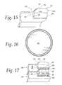
- FIG. 15is a partial cross-sectional view of a retention ring closure having a vent area and constructed in accordance with a further embodiment of the invention.
- FIG. 16is a bottom view of the closure of FIG. 15 and having a vent area therein;
- FIG. 17is a partial cross-sectional view of two closures of FIG. 15 stacked with a vent space therebetween;
- FIG. 18is a partial cross-sectional view of the closure of FIG. 7 having a vent area and constructed in accordance with a further embodiment of the invention.
- FIG. 19is a bottom view of the closure of FIG. 18 and having a vent area therein;
- FIG. 20is a partial cross-sectional view of two closures of FIG. 18 stacked together with a vent space therebetween.
- an injection-molded closure 10is made of polypropylene with a thin wall construction, for example, less than 0.020 inch in thickness, e.g., 0.018 inch in thickness, with a reduced amount of plastic being used and with good centering and stacking capabilities for use with automatic handling equipment.
- the lidis very low cost and has sufficient rigidity in a plane of central panel so that it can be used with packaging of various contents or applications including frozen applications.
- the closure 10secured to an injection-molded container 12 also made of material of any kind, usually polyethylene or polypropylene plastic.
- the closurein this instance is generally circular, and the container has an encircling, circular sidewall 14 with an upper beaded, container rim 16 which is engaged by the encircling connecting peripheral closure rim 18 .
- the closure rimis integrally connected to a central flat panel 20 in the closure 10 .
- a flat, annular top, rim ring 32abuts a top surface 33 of the container rim; and thus, the container is supporting the closure by engagement of these annular rings supporting surfaces 32 and 33 .
- the annular ring supporting surfaces 32are often called the “top panel” of the closure rim.
- the self-centering of the closures 10 within the stackis achieved by the use of a lower, nesting skirt, centering wall or portion 40 (FIG. 9) on the upper closure, which, if perfectly centered, is spaced by 0.002 inch from the adjacent nested wall of the adjacent closure.
- the upper nested wall of the upper closurewill abut and center itself on a nesting wall or portion 42 on a depending peripheral skirt 43 of the annular rim of the lower closure.
- the nesting skirt 40 and nesting wall portions 42are inwardly angled, or flared at an angle to the vertical, as illustrated in FIGS. 9-13.
- the nesting skirtcould be formed with a short vertical and horizontal wall portions at substantially 90° to one another with the upper closure having an outer bottom nesting wall of a larger diameter than an upper portion of the skirt of the lower closure.
- the inner surface 40 a of the flared skirt centering wallis dimensioned to be spaced from the facing outer surface 42 a of the flared, inclined surface 42 on the depending peripheral skirt 43 .
- a feeding ring or flange 46 at the bottom of the closure skirtslides down the inclined, flared, wall surface 42 a, thereby centering the upper closure on the lower closure.
- the downward sliding movementis arrested when the underside 48 of the retention shoulder 25 engages an outer corner portion 50 of the flat horizontal ring portion 32 at the top of the container rim 27 .
- the underside 48 of the undercut or retention bead 25 on the upper closureabuts corner 50 of the underlying ledge 32 of the lower closure to define a first, outer, stacking support and the second, inner, stacking support is constituted by stacking surfaces carried by vertical angular panel walls 60 abutting one another, as shown in FIGS. 9-13.
- the upper angular panel wall 60 of the upper closure 10 ahas a lower corner 62 with an underlying bottom surface 62 a which abuts an upper corner 65 on the underlying vertical rim wall 60 of the container 10 .
- the surface 62 a at the bottom cornerabuts a top surface 65 a at the top of the corner 65 .
- the prepared and illustrated closureis made from a polypropylene material which is fairly resistant to being brittle at the temperatures involved and the preferred polypropylene is available from Montell Corporation.
- the wall thickness for the vertical angular panel wall 60is 0.018 inch thick; and, in this instance, the central panel also has a thickness of 0.018 inch thick.
- the central panel 18remains substantially flat and planar for printing thereon and for cosmetic reasons.
- the top panel 32 of the closure rimis likewise about 0.018 inch in thickness as is the depending peripheral skirt 40 .
- the inclined sidewall 42 of the flared skirt portionhas an inclination at an angle A to the vertical of about 20° in this instance. Manifestly, such angle can be varied and still fall within the purview of the invention.
- the illustrated feed flange 46has a thickness of about 0.018 inch in the vertical direction between its top and bottom surfaces and projects outwardly for about 0.20 inch from the bottom of the peripheral skirt 40 .
- the top rimis defined by not only the radially outer horizontal ledge 32 , but also is defined by the radially inner, horizontal top panel 32 a and they are joined to one another by an inclined wall portion 32 b which is, in this instance, at an angle of about 30° to the vertical.
- a closure 10 bis provided with an annular, substantially flat, and substantially horizontal annular ring or surface 70 (FIG. 11) of the central panel 20 b which rests on the upper side of a foil or membrane seal 72 that is adhered to an underlying flat, horizontal surface 74 on a container 12 b.
- the membrane or foil disk 72is applied across the top of the container rim to cover and to seal the container contents from exposure to the atmosphere and ambient conditions, such as moisture in the ambient air.
- closures 10 bWhen the closures 10 b are stacked, the closures are centered by the lower flared skirt wall 40 b on the upper closure and an upper flared depending skirt 43 b on the lower closure; and the closures are stacked at the two points or areas of contact comprising the outer area of the undercut or retention shoulder 25 b engaging corner 50 b of the horizontal ledge 32 b and the inner area of contact with the vertical, angular panel, walls 60 b abutting one another.
- the closures 12 chave feeding flanges 46 b.
- the container rim 16 b of container 12 bis much wider in distance in the radial direction between its outer rim end 27 b and its inner vertical angular panel, wall 60 b than the distance between the rim wall 27 (FIG. 8) of the container 12 and its inner, angular panel wall 60 .
- This wider container rim 16 b on container 12 bprovides the wider surface 74 on which the membrane outer edge sits and seals with the surface 74 on the closure 10 b.
- the central plugincluding the central flat panel 20 , extend into the mouth of the container 12 ; whereas in the embodiment of FIG. 11, the central plug 20 b of the closure 12 b is above the horizontal foil 72 and above the mouth or lip of the container.
- the closure shown in FIG. 11is often called a flat closure because it doesn't have a plug.
- a closure 12 cis provided with an interrupted retention ring 80 (FIGS. 12-14) which projects upwardly from the upper corner 65 c of the vertical, angular panel wall 60 c and which serves to retain an informational disk 82 on the top central panel 20 c of the closure.
- the informational diskmay be an advertisement sheet about the product in the container or other material, such as a coupon, or the like, etc.
- the preferred retention ring 80comprises a series of spaced retention segments 80 c projecting upwardly and radially inwardly over circumferential end 82 c of the informational disk 82 on the central panel 20 c.
- the retention ringis comprised of six retention ring segments that are spaced from one another by gaps 84 where there is no retention ring segment projecting upwardly from the vertical rim wall 60 c.
- the number, size and shape of the retention ring wall segmentsmay be varied from that illustrated and described herein.
- the retention segmentprojects upwardly about 0.060 inch and is inclined at an angle of about 40° to the horizontal with a distance for an informational disk to be about 0.120 inch.
- Each retention segmentprojects radially inwardly from its vertical rim wall 60 c by about 0.051 inch in this instance.
- the closures 12 chave feeding rings 46 c.
- the retention ringis preferably segmented to allow flexing of the segments when the segments are stripped from the mold steel.
- polypropyleneis less flexible than polyethylene.
- the retention ringmay be a continuous ring ranter than a segmented ring, if so desired.
- the centeringis by use of lower flared skirt 40 c of the upper closure engaging upper flared skirt 43 c on the lower closure.
- Two points or areas of stacking supportare provided by the undercut, retaining bead shoulder 25 c on the upper closure 10 c resting on ledge 32 c of the lower closure 10 c and the radially inward area of contact between top edge 86 of retention ring 80 on the lower closure with the central panel 20 c of the upper closure 12 c.
- the retention ring segments 80 cconstitute projections or continuations of the vertical angular panel walls 60 c.
- the vertical angular panel walls 60 c of the stacked upper and lower closures 10 care spaced, as shown in FIG.
- Both of the embodiments of FIGS. 11 and 12are lightweight closures each preferably made of polypropylene and have a wall thickness of less than 0.020 inch, such as 0.018 inch wall thickness.
- a wall thickness of less than 0.020 inchsuch as 0.018 inch wall thickness.
- the weight of the lidis about 4.7 grams, by way of example only.
- the illustrated closure 12 c of FIG. 12is a larger closure having an outer diameter of 6.003 inch and its weight is only about 9.5 grams and its wall thickness is about 0.018 inch.
- the closuresare formed of polypropylene which has a high melt index, e.g., of 35 on the polypropylene melt index.
- a preferred polypropylene having the good flow characteristics and high strength characteristics suitable for use with cold or frozen foods in small cross-sectional closuresis sold by Montell Polyolefins, 800 Greenbank Road, Wilmington, Del. 19808, with only polypropylene being sold under the designation SG802N.
- other polypropylenesmay be supplied by others than this particular supplier to be used in this invention.
- these embodiments of the inventionprovide lightweight closures which do not have stacking ribs, but which use flared skirts for centering and two spaced areas of contact for stacking.
- the closure 10has a large central panel 20 that, when stacked, is spaced from another central panel to define an air space 90 (FIG. 20) therebetween.
- an air space 90FIG. 20
- some of the air between closuresmay be pushed out causing a slight negative air pressure or vacuum between the spaced closures at the space 90 (FIG. 20 ).
- This vacuummay cause the closures to stick together and not release the bottom closure as readily as desired with automatic capping machines when applying the closure to a container.
- closures described in FIGS. 1-12be provided with vent areas or spaces to allow air to flow between the closures in the stack to prevent a vacuum in the space 90 that would cause the lids to stick together.
- the closuresare vented to allow air to flow into and from the space 90 between central panels 20 of adjacent stacked closures by vents 92 that are formed by adding lugs 94 , which are spaced thickened areas at the bottom of the angular, vertical panel wall 60 of limited circumferential extent to provide vent spaces 92 a between adjacent lugs 94 .
- the lugs 94have a circumferential extent of about 22.5° with vent spaces 92 a of about 22.5° therebetween, as illustrated in FIG. 19 .
- eight lugs 94are provided and are equally spaced by eight vent spaces 92 a.
- the size and number of venting lugs or venting spacesmay be varied from that described for the illustrated embodiment of the invention of FIGS. 18-20.
- venting lugs 94are preferably formed by adding a small increments of plastic, e.g., 0.005 inch along the bottom corner 62 of the angular panel wall so that the underlying surface 62 a has eight lugs 94 of 45° in extent with each lug 94 projecting 0.005 inch beyond the adjacent vent areas on the underlying surface 62 a.
- a retention ring closure 100is formed with a retention ring 101 , which projects at an inclined angle upwardly from the upper corner 65 of the angular panel wall 60 and serves to retain an informational disk 82 on the top of the central panel 20 of closure.
- the retention ring 101is a continuous annular ring without being segmented and which has an upper edge or surface 102 that has vents 104 therein to allow air to flow into the space 90 between adjacent central panels 20 c of adjacent closures 100 .
- vents 104are formed by having lowered edge portions 102 a between raised edge portions 102 b in the upper edge 102 of the retention ring 80 . That is, the lower edge portions 102 a are located about 0.010 below the adjacent raised edge portions to form the vents 104 through which air flows into the space 90 between adjacent, central panels 20 c of stacked closures.
- six vents of 20° circumferential extentare provided and are spaced by six raised edge portions 102 b of 40° circumferential extent.
- the size and number of ventsmay be changed from that described above for the illustrated embodiment of the invention.
- the closures 100When nested, as seen in FIG. 17, the closures 100 have the space 90 between their respective central panels 20 c and further defined by an annular panel wall 60 and retention ring 101 when the upper edge portions 102 a of the bottom closure support the central panel 20 C of the closure thereabove.
- This space 90would be sealed if the top edge of the retention ring 101 was continuously engaging the central panel throughout 360° and a vacuum could be formed in the space 90 .
- the vents 104 formed by the lowered edge portions 102 a in the top edge of the retention ring 101allow air to flow to and from the space 90 to prevent the formation of a vacuum between the stacked closures 100 .
- the lowermost closurewill be unimpeded in its release from the stack.
- FIGS. 15-20are identical, except for the vents, with the closures described in FIGS. 1-14 and they stack in the same manner and are made of the same injection molded plastic materials as used for the closures of FIGS. 1-14 and described herein. Hence, a description of the stacking and materials used need not be repeated for the FIGS. 15-20 embodiment of the invention.
- the cornersare thicker than the walls meeting at the corner.
- other sections of the closuremay be thicker than the thin wall thickness, which is 0.018 inch in this instance.
- the feeding ring 46 at the bottom of the shirt 43provides a thicker cross-section than the remainder of the wall of the skirt 43 thereabove; the retention bead 25 on the nesting skirt wall portion 40 provides a thicker cross-sectional area in the skirt wall portion 40 ; and a thickened center portion is provided at the center of the top central panel 20 , as shown in FIG. 10 .
- the closurehas walls of varying cross-sectional thicknesses therein.
- the closure and containerare preferably both made of polypropylene and thin walled to provide a low cost, combination of a closure and container.
- the containers 12when filled with contents, are often stacked one upon another with a bottom wall 90 (FIG. 3) having a size and dimension with rounded corners 90 a around encircling the bottom of the container to fit within the plug shaped opening or impression 92 in the closure below. That is, in a stack of filled containers, the bottom wall of a filled container will rest on the upper side of the closure panel 20 on the filled container therebeneath.
- a feed flange 46 , 46 B and 46 Chas been provided in the lower end of the container rim 27 for use with certain automatic container handling equipment.
- the closure of the present inventioncan be made with or without a feed flange thereon.
Landscapes
- Engineering & Computer Science (AREA)
- Mechanical Engineering (AREA)
- Closures For Containers (AREA)
Abstract
Description
Claims (7)
Priority Applications (2)
| Application Number | Priority Date | Filing Date | Title |
|---|---|---|---|
| US09/571,634US6685049B1 (en) | 1999-11-19 | 2000-05-15 | Thin wall closure for use with a container |
| CA002326031ACA2326031C (en) | 1999-11-19 | 2000-11-16 | Thin wall closure container |
Applications Claiming Priority (2)
| Application Number | Priority Date | Filing Date | Title |
|---|---|---|---|
| US16657199P | 1999-11-19 | 1999-11-19 | |
| US09/571,634US6685049B1 (en) | 1999-11-19 | 2000-05-15 | Thin wall closure for use with a container |
Publications (1)
| Publication Number | Publication Date |
|---|---|
| US6685049B1true US6685049B1 (en) | 2004-02-03 |
Family
ID=26862366
Family Applications (1)
| Application Number | Title | Priority Date | Filing Date |
|---|---|---|---|
| US09/571,634Expired - LifetimeUS6685049B1 (en) | 1999-11-19 | 2000-05-15 | Thin wall closure for use with a container |
Country Status (2)
| Country | Link |
|---|---|
| US (1) | US6685049B1 (en) |
| CA (1) | CA2326031C (en) |
Cited By (44)
| Publication number | Priority date | Publication date | Assignee | Title |
|---|---|---|---|---|
| USD513376S1 (en) | 2004-09-08 | 2006-01-03 | Shannon Daniel P | Food container |
| US20060049073A1 (en)* | 2004-09-08 | 2006-03-09 | Shannon Daniel P | Thermoformed container |
| US20060091140A1 (en)* | 2004-10-28 | 2006-05-04 | Perry Michael R | Microwaveable packaged good article overcap |
| EP1693309A1 (en)* | 2005-02-22 | 2006-08-23 | Arta Plast Ab | Container |
| US20060186014A1 (en)* | 2005-02-23 | 2006-08-24 | Anand Ramanujam | Container |
| US20060266751A1 (en)* | 2004-10-28 | 2006-11-30 | El-Afandi Ali | Removable overcap for microwaveable packaged good article |
| USD546632S1 (en)* | 2006-11-07 | 2007-07-17 | Pwp Industries | Cookie container |
| US20070187277A1 (en)* | 2006-02-09 | 2007-08-16 | Rubbermaid Incorporated | Storage container and container system |
| US20070187407A1 (en)* | 2006-02-10 | 2007-08-16 | Berry Plastics Corporation | Canister with tamper-evident closure |
| US7261219B2 (en) | 1997-03-18 | 2007-08-28 | The Glad Products Company | Sealing container |
| US20080073368A1 (en)* | 2006-08-23 | 2008-03-27 | Richard Custer | Containers with discontinuous seal |
| USD568693S1 (en) | 2007-02-09 | 2008-05-13 | Rubbermaid Incorporated | Food storage container |
| US20090173656A1 (en)* | 2006-02-09 | 2009-07-09 | Rubbermaid Incorporated | Storage Container and Container System |
| US20100176022A1 (en)* | 2009-01-09 | 2010-07-15 | Rubbermaid Incorporated | Food storage container and container system |
| US20120247987A1 (en)* | 2011-04-01 | 2012-10-04 | Patterson Samuel J | Stackable water meter pit frames |
| USD719399S1 (en) | 2013-07-19 | 2014-12-16 | S. C. Johnson & Son, Inc. | Container |
| USD720178S1 (en) | 2013-07-19 | 2014-12-30 | S.C. Johnson & Son, Inc. | Container |
| USD721246S1 (en) | 2013-07-19 | 2015-01-20 | S. C. Johnson & Son, Inc. | Container |
| USD723864S1 (en) | 2013-07-19 | 2015-03-10 | S.C. Johnson & Son, Inc. | Container |
| USD724891S1 (en) | 2013-07-19 | 2015-03-24 | S.C. Johnson & Son, Inc. | Container |
| USD725433S1 (en) | 2013-07-19 | 2015-03-31 | S.C. Johnson & Son, Inc. | Container |
| US9108766B2 (en) | 2013-07-19 | 2015-08-18 | S.C. Johnson & Son, Inc. | Storage container systems |
| US9145251B2 (en) | 2012-10-26 | 2015-09-29 | Berry Plastics Corporation | Package |
| USD741171S1 (en) | 2013-07-19 | 2015-10-20 | S.C. Johnson & Son, Inc. | Container |
| USD741170S1 (en) | 2013-07-19 | 2015-10-20 | S.C. Johnson & Son, Inc. | Container |
| USD741708S1 (en) | 2013-10-10 | 2015-10-27 | S.C. Johnson & Son, Inc. | Container |
| USD742224S1 (en) | 2013-07-19 | 2015-11-03 | S.C. Johnson & Son, Inc. | Container |
| USD742743S1 (en) | 2013-10-10 | 2015-11-10 | S.C. Johnson & Son, Inc. | Container |
| USD744336S1 (en) | 2013-07-19 | 2015-12-01 | S.C. Johnson & Son, Inc. | Container lid |
| WO2016003603A1 (en)* | 2014-07-03 | 2016-01-07 | International Paper Company | Thermoformed articles from polypropylene polymer compositions |
| USD752973S1 (en) | 2013-07-19 | 2016-04-05 | S. C. Johnson & Son, Inc. | Container |
| USD760073S1 (en) | 2014-03-13 | 2016-06-28 | S.C. Johnson & Son, Inc. | Container |
| US9382047B2 (en)* | 2012-06-13 | 2016-07-05 | Michael Hoerauf Maschinenfabrik Gmbh U. Co. Kg | Multipart cover made of paper material and method for producing a multipart cover |
| US9604769B2 (en) | 2012-03-20 | 2017-03-28 | Berry Plastics Corporation | Stand up package |
| US10071835B1 (en)* | 2004-11-10 | 2018-09-11 | Rieke Corporation | Stackable molded cap |
| EP3385188A1 (en)* | 2017-04-05 | 2018-10-10 | Ipl Inc. | Container and method of fabrication thereof |
| US20190300236A1 (en)* | 2016-05-23 | 2019-10-03 | Å&R Carton Lund Aktiebolag | Packaging container with stacking members |
| US10532872B2 (en) | 2014-12-08 | 2020-01-14 | Berry Plastics Corporation | Package |
| CN111422500A (en)* | 2020-03-31 | 2020-07-17 | 南宁学院 | Fresh grape transportation packaging box |
| USD891924S1 (en)* | 2019-04-04 | 2020-08-04 | Jerry O. Mitchell | Beverage cap |
| US20230055070A1 (en)* | 2021-08-19 | 2023-02-23 | Closure Systems International Inc. | One-piece closure |
| EP4574699A1 (en)* | 2023-12-18 | 2025-06-25 | Thrace Plastics Pack SA | Reusable lid for cups for beverages |
| USD1093093S1 (en) | 2023-11-21 | 2025-09-16 | Kaz Europe Sàrl | Container |
| USD1093092S1 (en) | 2023-11-21 | 2025-09-16 | Kaz Europe Sàrl | Container |
Citations (29)
| Publication number | Priority date | Publication date | Assignee | Title |
|---|---|---|---|---|
| US1077235A (en)* | 1913-03-15 | 1913-10-28 | Nat Enameling And Stamping Company | Cylindric can-cover. |
| US3137409A (en)* | 1963-01-23 | 1964-06-16 | Sweetheart Plastics | Container cover |
| US3339786A (en)* | 1965-06-23 | 1967-09-05 | Owens Illinois Inc | Container and venting closure cap for same |
| US3353708A (en)* | 1965-03-15 | 1967-11-21 | Sweetheart Plastics | Disposable plastic article |
| US3424342A (en)* | 1967-08-14 | 1969-01-28 | Monsanto Co | Container |
| US3642167A (en)* | 1970-07-20 | 1972-02-15 | Phillips Petroleum Co | Container closure |
| US3664544A (en)* | 1970-02-21 | 1972-05-23 | Wilhelm Hammes | Container construction |
| US3722731A (en)* | 1969-05-23 | 1973-03-27 | Dow Chemical Co | Inset coverall lid for containers |
| US3724710A (en)* | 1970-11-05 | 1973-04-03 | Sweetheart Plastics | Container lid |
| US3931890A (en)* | 1974-06-27 | 1976-01-13 | Sweetheart Plastics, Inc. | Stackable lid |
| US4014459A (en)* | 1975-10-08 | 1977-03-29 | Go-Jo Industries, Inc. | Container closure |
| US4138034A (en)* | 1976-08-05 | 1979-02-06 | The Procter & Gamble Company | Package for discrete pre-moistened interleaved sheets and the pop-up dispensing thereof |
| US4166548A (en)* | 1978-05-30 | 1979-09-04 | Polysar Resins, Inc. | Containers and closures therefor |
| US4194645A (en)* | 1978-10-10 | 1980-03-25 | Nyman Mfg. Co. | Container cover construction |
| US4341324A (en)* | 1980-07-09 | 1982-07-27 | Dolco Packaging Corporation | Bowl and cover assembly |
| US4364476A (en)* | 1982-01-05 | 1982-12-21 | Shamrock Industries, Inc. | Plastic lid with stacking separation means |
| US4407426A (en)* | 1980-04-04 | 1983-10-04 | Champion International Corporation | Round ice cream carton lid |
| US4632265A (en)* | 1983-06-24 | 1986-12-30 | Cochrane Benjamin A | Press-on cap and seal |
| US4811860A (en)* | 1988-07-12 | 1989-03-14 | Sccs, Incorporated | Nestable disposable drinking receptacles |
| US4817801A (en)* | 1987-03-06 | 1989-04-04 | Reynolds Metals Company | Two piece package for paper baking cups |
| US4844263A (en)* | 1988-02-19 | 1989-07-04 | Hercules, Incorporated | Food container |
| US4854472A (en)* | 1988-06-10 | 1989-08-08 | Plastic Technologies, Inc. | Tamper resistant wide mouth package with dynamic seal |
| US4856674A (en)* | 1987-11-03 | 1989-08-15 | Reliance Products, Division Of Larson Mardon Group Limited | Cover for plastic container |
| US4872304A (en)* | 1985-12-12 | 1989-10-10 | Tri-Tech Systems International Inc. | Closure cap with a seal and method of and apparatus for forming such closure and seal |
| US4886184A (en)* | 1989-01-23 | 1989-12-12 | Hamelin Group Inc. | Plastic container lid |
| US5046632A (en)* | 1990-02-22 | 1991-09-10 | Bordner Paul G | Closure assembly for fiber container including a molded lid with multi-mode closure orientations |
| US5385255A (en)* | 1993-11-23 | 1995-01-31 | Sherwood Tool, Inc. | Snap-on lid |
| US5904266A (en)* | 1997-10-21 | 1999-05-18 | Kraft Foods Inc. | Product package and stackable lid assembly therefor |
| US5960985A (en)* | 1996-10-03 | 1999-10-05 | Barrett; Robert K. | Container lid and container |
- 2000
- 2000-05-15USUS09/571,634patent/US6685049B1/ennot_activeExpired - Lifetime
- 2000-11-16CACA002326031Apatent/CA2326031C/ennot_activeExpired - Lifetime
Patent Citations (29)
| Publication number | Priority date | Publication date | Assignee | Title |
|---|---|---|---|---|
| US1077235A (en)* | 1913-03-15 | 1913-10-28 | Nat Enameling And Stamping Company | Cylindric can-cover. |
| US3137409A (en)* | 1963-01-23 | 1964-06-16 | Sweetheart Plastics | Container cover |
| US3353708A (en)* | 1965-03-15 | 1967-11-21 | Sweetheart Plastics | Disposable plastic article |
| US3339786A (en)* | 1965-06-23 | 1967-09-05 | Owens Illinois Inc | Container and venting closure cap for same |
| US3424342A (en)* | 1967-08-14 | 1969-01-28 | Monsanto Co | Container |
| US3722731A (en)* | 1969-05-23 | 1973-03-27 | Dow Chemical Co | Inset coverall lid for containers |
| US3664544A (en)* | 1970-02-21 | 1972-05-23 | Wilhelm Hammes | Container construction |
| US3642167A (en)* | 1970-07-20 | 1972-02-15 | Phillips Petroleum Co | Container closure |
| US3724710A (en)* | 1970-11-05 | 1973-04-03 | Sweetheart Plastics | Container lid |
| US3931890A (en)* | 1974-06-27 | 1976-01-13 | Sweetheart Plastics, Inc. | Stackable lid |
| US4014459A (en)* | 1975-10-08 | 1977-03-29 | Go-Jo Industries, Inc. | Container closure |
| US4138034A (en)* | 1976-08-05 | 1979-02-06 | The Procter & Gamble Company | Package for discrete pre-moistened interleaved sheets and the pop-up dispensing thereof |
| US4166548A (en)* | 1978-05-30 | 1979-09-04 | Polysar Resins, Inc. | Containers and closures therefor |
| US4194645A (en)* | 1978-10-10 | 1980-03-25 | Nyman Mfg. Co. | Container cover construction |
| US4407426A (en)* | 1980-04-04 | 1983-10-04 | Champion International Corporation | Round ice cream carton lid |
| US4341324A (en)* | 1980-07-09 | 1982-07-27 | Dolco Packaging Corporation | Bowl and cover assembly |
| US4364476A (en)* | 1982-01-05 | 1982-12-21 | Shamrock Industries, Inc. | Plastic lid with stacking separation means |
| US4632265A (en)* | 1983-06-24 | 1986-12-30 | Cochrane Benjamin A | Press-on cap and seal |
| US4872304A (en)* | 1985-12-12 | 1989-10-10 | Tri-Tech Systems International Inc. | Closure cap with a seal and method of and apparatus for forming such closure and seal |
| US4817801A (en)* | 1987-03-06 | 1989-04-04 | Reynolds Metals Company | Two piece package for paper baking cups |
| US4856674A (en)* | 1987-11-03 | 1989-08-15 | Reliance Products, Division Of Larson Mardon Group Limited | Cover for plastic container |
| US4844263A (en)* | 1988-02-19 | 1989-07-04 | Hercules, Incorporated | Food container |
| US4854472A (en)* | 1988-06-10 | 1989-08-08 | Plastic Technologies, Inc. | Tamper resistant wide mouth package with dynamic seal |
| US4811860A (en)* | 1988-07-12 | 1989-03-14 | Sccs, Incorporated | Nestable disposable drinking receptacles |
| US4886184A (en)* | 1989-01-23 | 1989-12-12 | Hamelin Group Inc. | Plastic container lid |
| US5046632A (en)* | 1990-02-22 | 1991-09-10 | Bordner Paul G | Closure assembly for fiber container including a molded lid with multi-mode closure orientations |
| US5385255A (en)* | 1993-11-23 | 1995-01-31 | Sherwood Tool, Inc. | Snap-on lid |
| US5960985A (en)* | 1996-10-03 | 1999-10-05 | Barrett; Robert K. | Container lid and container |
| US5904266A (en)* | 1997-10-21 | 1999-05-18 | Kraft Foods Inc. | Product package and stackable lid assembly therefor |
Cited By (73)
| Publication number | Priority date | Publication date | Assignee | Title |
|---|---|---|---|---|
| US7261219B2 (en) | 1997-03-18 | 2007-08-28 | The Glad Products Company | Sealing container |
| US20060049073A1 (en)* | 2004-09-08 | 2006-03-09 | Shannon Daniel P | Thermoformed container |
| USD513376S1 (en) | 2004-09-08 | 2006-01-03 | Shannon Daniel P | Food container |
| US20060091140A1 (en)* | 2004-10-28 | 2006-05-04 | Perry Michael R | Microwaveable packaged good article overcap |
| US8011524B2 (en)* | 2004-10-28 | 2011-09-06 | General Mills Cereals, Llc | Microwaveable packaged good article overcap |
| US7861881B2 (en)* | 2004-10-28 | 2011-01-04 | General Mills Cereals, Llc. | Removable overcap for microwaveable packaged good article |
| US20060266751A1 (en)* | 2004-10-28 | 2006-11-30 | El-Afandi Ali | Removable overcap for microwaveable packaged good article |
| US10723517B2 (en) | 2004-11-10 | 2020-07-28 | Rieke Llc | Stackable molded cap |
| US20190002165A1 (en)* | 2004-11-10 | 2019-01-03 | Rieke Corporation | Stackable molded cap |
| US20190112108A1 (en)* | 2004-11-10 | 2019-04-18 | Rieke Corporation | Stackable molded cap |
| US10071835B1 (en)* | 2004-11-10 | 2018-09-11 | Rieke Corporation | Stackable molded cap |
| US10618699B2 (en) | 2004-11-10 | 2020-04-14 | Rieke Llc | Stackable molded cap |
| US11117712B2 (en) | 2004-11-10 | 2021-09-14 | Rieke Llc | Stackable molded cap |
| US20060186120A1 (en)* | 2005-02-22 | 2006-08-24 | Henning Steg | Container |
| US8746499B2 (en)* | 2005-02-22 | 2014-06-10 | Arta Plast Ab | Container |
| EP1693309A1 (en)* | 2005-02-22 | 2006-08-23 | Arta Plast Ab | Container |
| US7726483B2 (en)* | 2005-02-23 | 2010-06-01 | The Glad Products Company | Stacked containers |
| US20100170824A1 (en)* | 2005-02-23 | 2010-07-08 | The Glad Products Company | Container |
| US20060186014A1 (en)* | 2005-02-23 | 2006-08-24 | Anand Ramanujam | Container |
| US9145231B2 (en) | 2006-02-09 | 2015-09-29 | Rubbermaid Incorporated | Storage container and container system |
| US20090173656A1 (en)* | 2006-02-09 | 2009-07-09 | Rubbermaid Incorporated | Storage Container and Container System |
| US20070187277A1 (en)* | 2006-02-09 | 2007-08-16 | Rubbermaid Incorporated | Storage container and container system |
| US8322530B2 (en) | 2006-02-09 | 2012-12-04 | Rubbermaid Incorporated | Storage container and container system |
| US8777043B2 (en) | 2006-02-09 | 2014-07-15 | Rubbermaid Incorporated | Storage container and container system |
| WO2007092954A3 (en)* | 2006-02-09 | 2007-09-27 | Rubbermaid Inc | Storage container and container system |
| US20070187407A1 (en)* | 2006-02-10 | 2007-08-16 | Berry Plastics Corporation | Canister with tamper-evident closure |
| US20080073368A1 (en)* | 2006-08-23 | 2008-03-27 | Richard Custer | Containers with discontinuous seal |
| USD546632S1 (en)* | 2006-11-07 | 2007-07-17 | Pwp Industries | Cookie container |
| USD585699S1 (en) | 2007-02-09 | 2009-02-03 | Rubbermaid Incorporated | Container lid |
| USD568693S1 (en) | 2007-02-09 | 2008-05-13 | Rubbermaid Incorporated | Food storage container |
| USD568694S1 (en) | 2007-02-09 | 2008-05-13 | Rubbermaid Incorporated | Food storage container |
| USD586179S1 (en) | 2007-02-09 | 2009-02-10 | Rubbermaid Incorporated | Container lid |
| US8967416B2 (en) | 2009-01-09 | 2015-03-03 | Rubbermaid Incorporated | Food storage container and container system |
| US20100176022A1 (en)* | 2009-01-09 | 2010-07-15 | Rubbermaid Incorporated | Food storage container and container system |
| US20120247987A1 (en)* | 2011-04-01 | 2012-10-04 | Patterson Samuel J | Stackable water meter pit frames |
| US9604769B2 (en) | 2012-03-20 | 2017-03-28 | Berry Plastics Corporation | Stand up package |
| US9382047B2 (en)* | 2012-06-13 | 2016-07-05 | Michael Hoerauf Maschinenfabrik Gmbh U. Co. Kg | Multipart cover made of paper material and method for producing a multipart cover |
| US9145251B2 (en) | 2012-10-26 | 2015-09-29 | Berry Plastics Corporation | Package |
| US9884716B2 (en) | 2012-10-26 | 2018-02-06 | Berry Plastics Corporation | Package |
| US10138020B2 (en) | 2013-07-19 | 2018-11-27 | S. C. Johnson & Son, Inc. | Storage container systems |
| USD723864S1 (en) | 2013-07-19 | 2015-03-10 | S.C. Johnson & Son, Inc. | Container |
| USD719399S1 (en) | 2013-07-19 | 2014-12-16 | S. C. Johnson & Son, Inc. | Container |
| USD744336S1 (en) | 2013-07-19 | 2015-12-01 | S.C. Johnson & Son, Inc. | Container lid |
| USD911098S1 (en) | 2013-07-19 | 2021-02-23 | S. C. Johnson & Son, Inc. | Container lid |
| USD752973S1 (en) | 2013-07-19 | 2016-04-05 | S. C. Johnson & Son, Inc. | Container |
| USD720178S1 (en) | 2013-07-19 | 2014-12-30 | S.C. Johnson & Son, Inc. | Container |
| USD741171S1 (en) | 2013-07-19 | 2015-10-20 | S.C. Johnson & Son, Inc. | Container |
| US9108766B2 (en) | 2013-07-19 | 2015-08-18 | S.C. Johnson & Son, Inc. | Storage container systems |
| US9682799B2 (en) | 2013-07-19 | 2017-06-20 | S. C. Johnson & Son, Inc. | Storage container systems |
| USD721246S1 (en) | 2013-07-19 | 2015-01-20 | S. C. Johnson & Son, Inc. | Container |
| US10583961B2 (en) | 2013-07-19 | 2020-03-10 | S. C. Johnson & Son, Inc. | Storage container systems |
| USD725433S1 (en) | 2013-07-19 | 2015-03-31 | S.C. Johnson & Son, Inc. | Container |
| USD829545S1 (en) | 2013-07-19 | 2018-10-02 | S. C. Johnson & Son, Inc. | Container bowl |
| USD797552S1 (en) | 2013-07-19 | 2017-09-19 | S.C. Johnson & Son, Inc. | Container |
| USD741170S1 (en) | 2013-07-19 | 2015-10-20 | S.C. Johnson & Son, Inc. | Container |
| USD742224S1 (en) | 2013-07-19 | 2015-11-03 | S.C. Johnson & Son, Inc. | Container |
| USD724891S1 (en) | 2013-07-19 | 2015-03-24 | S.C. Johnson & Son, Inc. | Container |
| USD741708S1 (en) | 2013-10-10 | 2015-10-27 | S.C. Johnson & Son, Inc. | Container |
| USD742743S1 (en) | 2013-10-10 | 2015-11-10 | S.C. Johnson & Son, Inc. | Container |
| USD760073S1 (en) | 2014-03-13 | 2016-06-28 | S.C. Johnson & Son, Inc. | Container |
| WO2016003603A1 (en)* | 2014-07-03 | 2016-01-07 | International Paper Company | Thermoformed articles from polypropylene polymer compositions |
| USRE50333E1 (en) | 2014-12-08 | 2025-03-11 | Berry Global, Inc. | Package |
| US10532872B2 (en) | 2014-12-08 | 2020-01-14 | Berry Plastics Corporation | Package |
| US20190300236A1 (en)* | 2016-05-23 | 2019-10-03 | Å&R Carton Lund Aktiebolag | Packaging container with stacking members |
| US11192688B2 (en)* | 2016-05-23 | 2021-12-07 | Ar Packaging Systems Ab | Packaging container with stacking members |
| EP3385188A1 (en)* | 2017-04-05 | 2018-10-10 | Ipl Inc. | Container and method of fabrication thereof |
| USD891924S1 (en)* | 2019-04-04 | 2020-08-04 | Jerry O. Mitchell | Beverage cap |
| CN111422500A (en)* | 2020-03-31 | 2020-07-17 | 南宁学院 | Fresh grape transportation packaging box |
| US20230055070A1 (en)* | 2021-08-19 | 2023-02-23 | Closure Systems International Inc. | One-piece closure |
| US12065295B2 (en)* | 2021-08-19 | 2024-08-20 | Closure Systems International Inc. | One-piece closure |
| USD1093093S1 (en) | 2023-11-21 | 2025-09-16 | Kaz Europe Sàrl | Container |
| USD1093092S1 (en) | 2023-11-21 | 2025-09-16 | Kaz Europe Sàrl | Container |
| EP4574699A1 (en)* | 2023-12-18 | 2025-06-25 | Thrace Plastics Pack SA | Reusable lid for cups for beverages |
Also Published As
| Publication number | Publication date |
|---|---|
| CA2326031C (en) | 2007-09-04 |
| CA2326031A1 (en) | 2001-05-19 |
Similar Documents
| Publication | Publication Date | Title |
|---|---|---|
| US6685049B1 (en) | Thin wall closure for use with a container | |
| US4076123A (en) | Disposable plastic lid | |
| US4418833A (en) | Large volume container with gasketless seal | |
| US4782976A (en) | Tamper-evident canister, lid and shrink band assembly | |
| US5592766A (en) | Container lid/closure with printed closure insert | |
| US3519163A (en) | Container and closure therefor | |
| US3967731A (en) | Stackable lid and container | |
| CA2127311C (en) | Double seal food container | |
| US3743133A (en) | Lid and container | |
| US3840152A (en) | Sealable and resealable container | |
| US4332332A (en) | Container and closure having frangible opening means | |
| US3321104A (en) | Coin fed lid | |
| US6325213B1 (en) | Plastic container for food products | |
| US3178051A (en) | Container and lid | |
| US4421244A (en) | Plastic lid for containers | |
| US6213301B1 (en) | Plastic container for food products | |
| US3353707A (en) | Nestable container | |
| US3927766A (en) | Cups for holding ingredients for drinks | |
| US3452896A (en) | Container | |
| US4457447A (en) | Plastic pail and lid | |
| US5540349A (en) | Container closure with separable wall segments | |
| US3516572A (en) | Closure having double fastening means | |
| US4051951A (en) | Package having means for providing coaxial alignment in a stack thereof | |
| US3349950A (en) | Container with segmented lid seat | |
| US4817801A (en) | Two piece package for paper baking cups |
Legal Events
| Date | Code | Title | Description |
|---|---|---|---|
| AS | Assignment | Owner name:LANDIS PLASTICS, INC., ILLINOIS Free format text:ASSIGNMENT OF ASSIGNORS INTEREST;ASSIGNOR:PALADINO, JASON JOSEPH;REEL/FRAME:010823/0227 Effective date:20000428 | |
| STCF | Information on status: patent grant | Free format text:PATENTED CASE | |
| AS | Assignment | Owner name:FLEET NATIONAL BANK, AS COLLATERAL AGENT, MASSACHU Free format text:SECURITY AGREEMENT;ASSIGNOR:LANDIS PLASTICS, INC.;REEL/FRAME:016087/0454 Effective date:20031120 | |
| AS | Assignment | Owner name:DEUTSCHE BANK TRUST COMPANY AMERICAS, ILLINOIS Free format text:ASSIGNMENT OF SECURITY INTEREST;ASSIGNOR:FLEET NATIONAL BANK;REEL/FRAME:016164/0272 Effective date:20050603 | |
| AS | Assignment | Owner name:CREDIT SUISSE, AS ADMINISTRATIVE AGENT, NEW YORK Free format text:SECURITY AGREEMENT;ASSIGNOR:LANDIS PLASTICS, INC.;REEL/FRAME:018291/0437 Effective date:20060920 | |
| AS | Assignment | Owner name:WELLS FARGO BANK, N.A., AS COLLATERAL AGENT,CONNEC Free format text:SECOND LIEN PATENT SECURITY AGREEMENT;ASSIGNORS:BERRY PLASTICS CORPORATION;BERRY STERLING CORPORATION;KERR GROUP, INC.;AND OTHERS;REEL/FRAME:018407/0074 Effective date:20060920 Owner name:WELLS FARGO BANK, N.A., AS COLLATERAL AGENT, CONNE Free format text:SECOND LIEN PATENT SECURITY AGREEMENT;ASSIGNORS:BERRY PLASTICS CORPORATION;BERRY STERLING CORPORATION;KERR GROUP, INC.;AND OTHERS;REEL/FRAME:018407/0074 Effective date:20060920 | |
| AS | Assignment | Owner name:BANK OF AMERICA, N.A., AS ABL COLLATERAL AGENT,NOR Free format text:SECOND AMENDED AND RESTATED FIRST LIEN INTELLECTUAL PROPERTY SECURITY AGREEMENT;ASSIGNOR:BERRY PLASTICS HOLDING CORPORATION;REEL/FRAME:019147/0479 Effective date:20070403 Owner name:CREDIT SUISSE, CAYMAN ISLANDS BRANCH, AS TERM COLL Free format text:SECOND AMENDED AND RESTATED FIRST LIEN INTELLECTUAL PROPERTY SECURITY AGREEMENT;ASSIGNOR:BERRY PLASTICS HOLDING CORPORATION;REEL/FRAME:019147/0479 Effective date:20070403 Owner name:BANK OF AMERICA, N.A., AS ABL COLLATERAL AGENT, NO Free format text:SECOND AMENDED AND RESTATED FIRST LIEN INTELLECTUAL PROPERTY SECURITY AGREEMENT;ASSIGNOR:BERRY PLASTICS HOLDING CORPORATION;REEL/FRAME:019147/0479 Effective date:20070403 | |
| FPAY | Fee payment | Year of fee payment:4 | |
| AS | Assignment | Owner name:BANK OF AMERICA, N.A., AS COLLATERAL AGENT, CALIFO Free format text:BRIDGE LOAN FIRST LIEN INTELLECTUAL PROPERTY SECURITY AGREEMENT;ASSIGNORS:BERRY PLASTICS CORPORATION;BERRY STERLING CORPORATION;CAPTIVE PLASTICS, INC.;AND OTHERS;REEL/FRAME:020638/0249 Effective date:20080205 Owner name:BANK OF AMERICA, N.A., AS COLLATERAL AGENT,CALIFOR Free format text:BRIDGE LOAN FIRST LIEN INTELLECTUAL PROPERTY SECURITY AGREEMENT;ASSIGNORS:BERRY PLASTICS CORPORATION;BERRY STERLING CORPORATION;CAPTIVE PLASTICS, INC.;AND OTHERS;REEL/FRAME:020638/0249 Effective date:20080205 | |
| AS | Assignment | Owner name:BERRY PLASTICS CORPORATION, INDIANA Free format text:RELEASE OF BRIDGE 1ST LIEN SECURITY AGREEMENT;ASSIGNOR:BANK OF AMERICA, N.A.;REEL/FRAME:020845/0198 Effective date:20080421 Owner name:BERRY STERLING CORPORATION, INDIANA Free format text:RELEASE OF BRIDGE 1ST LIEN SECURITY AGREEMENT;ASSIGNOR:BANK OF AMERICA, N.A.;REEL/FRAME:020845/0198 Effective date:20080421 Owner name:CAPTIVE PLASTICS, INC., NEW JERSEY Free format text:RELEASE OF BRIDGE 1ST LIEN SECURITY AGREEMENT;ASSIGNOR:BANK OF AMERICA, N.A.;REEL/FRAME:020845/0198 Effective date:20080421 Owner name:GRAFCO INDUSTRIES LIMITED PARTNERSHIP, NEW JERSEY Free format text:RELEASE OF BRIDGE 1ST LIEN SECURITY AGREEMENT;ASSIGNOR:BANK OF AMERICA, N.A.;REEL/FRAME:020845/0198 Effective date:20080421 Owner name:LANDIS PLASTICS, LLC, ILLINOIS Free format text:RELEASE OF BRIDGE 1ST LIEN SECURITY AGREEMENT;ASSIGNOR:BANK OF AMERICA, N.A.;REEL/FRAME:020845/0198 Effective date:20080421 Owner name:SETCO, LLC, CALIFORNIA Free format text:RELEASE OF BRIDGE 1ST LIEN SECURITY AGREEMENT;ASSIGNOR:BANK OF AMERICA, N.A.;REEL/FRAME:020845/0198 Effective date:20080421 Owner name:TUBED PRODUCTS, LLC, MASSACHUSETTS Free format text:RELEASE OF BRIDGE 1ST LIEN SECURITY AGREEMENT;ASSIGNOR:BANK OF AMERICA, N.A.;REEL/FRAME:020845/0198 Effective date:20080421 Owner name:WELLS FARGO BANK, N.A., CONNECTICUT Free format text:SECURITY AGREEMENT;ASSIGNORS:BERRY PLASTICS CORPORATION;BERRY STERLING CORPORATION;CAPTIVE PLASTICS, INC.;AND OTHERS;REEL/FRAME:020845/0301 Effective date:20080421 Owner name:BERRY PLASTICS CORPORATION,INDIANA Free format text:RELEASE OF BRIDGE 1ST LIEN SECURITY AGREEMENT;ASSIGNOR:BANK OF AMERICA, N.A.;REEL/FRAME:020845/0198 Effective date:20080421 Owner name:BERRY STERLING CORPORATION,INDIANA Free format text:RELEASE OF BRIDGE 1ST LIEN SECURITY AGREEMENT;ASSIGNOR:BANK OF AMERICA, N.A.;REEL/FRAME:020845/0198 Effective date:20080421 Owner name:CAPTIVE PLASTICS, INC.,NEW JERSEY Free format text:RELEASE OF BRIDGE 1ST LIEN SECURITY AGREEMENT;ASSIGNOR:BANK OF AMERICA, N.A.;REEL/FRAME:020845/0198 Effective date:20080421 Owner name:GRAFCO INDUSTRIES LIMITED PARTNERSHIP,NEW JERSEY Free format text:RELEASE OF BRIDGE 1ST LIEN SECURITY AGREEMENT;ASSIGNOR:BANK OF AMERICA, N.A.;REEL/FRAME:020845/0198 Effective date:20080421 Owner name:LANDIS PLASTICS, LLC,ILLINOIS Free format text:RELEASE OF BRIDGE 1ST LIEN SECURITY AGREEMENT;ASSIGNOR:BANK OF AMERICA, N.A.;REEL/FRAME:020845/0198 Effective date:20080421 Owner name:SETCO, LLC,CALIFORNIA Free format text:RELEASE OF BRIDGE 1ST LIEN SECURITY AGREEMENT;ASSIGNOR:BANK OF AMERICA, N.A.;REEL/FRAME:020845/0198 Effective date:20080421 Owner name:TUBED PRODUCTS, LLC,MASSACHUSETTS Free format text:RELEASE OF BRIDGE 1ST LIEN SECURITY AGREEMENT;ASSIGNOR:BANK OF AMERICA, N.A.;REEL/FRAME:020845/0198 Effective date:20080421 Owner name:WELLS FARGO BANK, N.A.,CONNECTICUT Free format text:SECURITY AGREEMENT;ASSIGNORS:BERRY PLASTICS CORPORATION;BERRY STERLING CORPORATION;CAPTIVE PLASTICS, INC.;AND OTHERS;REEL/FRAME:020845/0301 Effective date:20080421 | |
| AS | Assignment | Owner name:BERRY PLASTICS CORPORATION, INDIANA Free format text:RELEASE OF SECURITY INTEREST RECORDED AT REEL 016164 FRAME 0272;ASSIGNOR:DEUTSCHE BANK TRUST COMPANY AMERICAS;REEL/FRAME:020866/0464 Effective date:20060910 | |
| FPAY | Fee payment | Year of fee payment:8 | |
| FPAY | Fee payment | Year of fee payment:12 | |
| AS | Assignment | Owner name:SETCO, LLC, CALIFORNIA Free format text:RELEASE BY SECURED PARTY;ASSIGNOR:WELLS FARGO BANK, N.A., AS COLLATERAL AGENT;REEL/FRAME:049598/0731 Effective date:20190625 Owner name:BERRY GLOBAL, INC., INDIANA Free format text:RELEASE BY SECURED PARTY;ASSIGNOR:WELLS FARGO BANK, N.A., AS COLLATERAL AGENT;REEL/FRAME:049598/0731 Effective date:20190625 Owner name:KERR GROUP, LLC, CALIFORNIA Free format text:RELEASE BY SECURED PARTY;ASSIGNOR:WELLS FARGO BANK, N.A., AS COLLATERAL AGENT;REEL/FRAME:049598/0731 Effective date:20190625 Owner name:TUBED PRODUCTS LLC, MASSACHUSETTS Free format text:RELEASE BY SECURED PARTY;ASSIGNOR:WELLS FARGO BANK, N.A., AS COLLATERAL AGENT;REEL/FRAME:049598/0731 Effective date:20190625 Owner name:CAPTIVE PLASTICS, INC., NEW JERSEY Free format text:RELEASE BY SECURED PARTY;ASSIGNOR:WELLS FARGO BANK, N.A., AS COLLATERAL AGENT;REEL/FRAME:049598/0731 Effective date:20190625 Owner name:PESCOR, INC., TEXAS Free format text:RELEASE BY SECURED PARTY;ASSIGNOR:WELLS FARGO BANK, N.A., AS COLLATERAL AGENT;REEL/FRAME:049598/0731 Effective date:20190625 Owner name:BERRY STERLING CORPORATION, INDIANA Free format text:RELEASE BY SECURED PARTY;ASSIGNOR:WELLS FARGO BANK, N.A., AS COLLATERAL AGENT;REEL/FRAME:049598/0731 Effective date:20190625 Owner name:LANDIS PLASTICS, LLC, DELAWARE Free format text:RELEASE BY SECURED PARTY;ASSIGNOR:WELLS FARGO BANK, N.A., AS COLLATERAL AGENT;REEL/FRAME:049598/0731 Effective date:20190625 Owner name:GRAFCO INDUSTRIES LIMITED PARTNERSHIP, NEW JERSEY Free format text:RELEASE BY SECURED PARTY;ASSIGNOR:WELLS FARGO BANK, N.A., AS COLLATERAL AGENT;REEL/FRAME:049598/0731 Effective date:20190625 | |
| AS | Assignment | Owner name:F&S TOOL, INC., INDIANA Free format text:RELEASE OF PATENT SECURITY INTERESTS;ASSIGNORS:UBS AG, STAMFORD BRANCH (SUCCESSOR TO CREDIT SUISSE AG, CAYMAN ISLANDS BRANCH), AS TERM LOAN COLLATERAL AGENT;BANK OF AMERICA, N.A., AS ABL COLLATERAL AGENT;REEL/FRAME:071168/0009 Effective date:20250430 Owner name:ROLLPAK CORPORATION, INDIANA Free format text:RELEASE OF PATENT SECURITY INTERESTS;ASSIGNORS:UBS AG, STAMFORD BRANCH (SUCCESSOR TO CREDIT SUISSE AG, CAYMAN ISLANDS BRANCH), AS TERM LOAN COLLATERAL AGENT;BANK OF AMERICA, N.A., AS ABL COLLATERAL AGENT;REEL/FRAME:071168/0009 Effective date:20250430 Owner name:PLIANT, LLC, INDIANA Free format text:RELEASE OF PATENT SECURITY INTERESTS;ASSIGNORS:UBS AG, STAMFORD BRANCH (SUCCESSOR TO CREDIT SUISSE AG, CAYMAN ISLANDS BRANCH), AS TERM LOAN COLLATERAL AGENT;BANK OF AMERICA, N.A., AS ABL COLLATERAL AGENT;REEL/FRAME:071168/0009 Effective date:20250430 Owner name:LETICA RESOURCES, INC., INDIANA Free format text:RELEASE OF PATENT SECURITY INTERESTS;ASSIGNORS:UBS AG, STAMFORD BRANCH (SUCCESSOR TO CREDIT SUISSE AG, CAYMAN ISLANDS BRANCH), AS TERM LOAN COLLATERAL AGENT;BANK OF AMERICA, N.A., AS ABL COLLATERAL AGENT;REEL/FRAME:071168/0009 Effective date:20250430 Owner name:LETICA CORPORATION, INDIANA Free format text:RELEASE OF PATENT SECURITY INTERESTS;ASSIGNORS:UBS AG, STAMFORD BRANCH (SUCCESSOR TO CREDIT SUISSE AG, CAYMAN ISLANDS BRANCH), AS TERM LOAN COLLATERAL AGENT;BANK OF AMERICA, N.A., AS ABL COLLATERAL AGENT;REEL/FRAME:071168/0009 Effective date:20250430 Owner name:KERR GROUP, LLC, INDIANA Free format text:RELEASE OF PATENT SECURITY INTERESTS;ASSIGNORS:UBS AG, STAMFORD BRANCH (SUCCESSOR TO CREDIT SUISSE AG, CAYMAN ISLANDS BRANCH), AS TERM LOAN COLLATERAL AGENT;BANK OF AMERICA, N.A., AS ABL COLLATERAL AGENT;REEL/FRAME:071168/0009 Effective date:20250430 Owner name:FIBERWEB, LLC, INDIANA Free format text:RELEASE OF PATENT SECURITY INTERESTS;ASSIGNORS:UBS AG, STAMFORD BRANCH (SUCCESSOR TO CREDIT SUISSE AG, CAYMAN ISLANDS BRANCH), AS TERM LOAN COLLATERAL AGENT;BANK OF AMERICA, N.A., AS ABL COLLATERAL AGENT;REEL/FRAME:071168/0009 Effective date:20250430 Owner name:FIBERWEB, INC., INDIANA Free format text:RELEASE OF PATENT SECURITY INTERESTS;ASSIGNORS:UBS AG, STAMFORD BRANCH (SUCCESSOR TO CREDIT SUISSE AG, CAYMAN ISLANDS BRANCH), AS TERM LOAN COLLATERAL AGENT;BANK OF AMERICA, N.A., AS ABL COLLATERAL AGENT;REEL/FRAME:071168/0009 Effective date:20250430 Owner name:COVALENCE SPECIALTY ADHESIVES LLC, INDIANA Free format text:RELEASE OF PATENT SECURITY INTERESTS;ASSIGNORS:UBS AG, STAMFORD BRANCH (SUCCESSOR TO CREDIT SUISSE AG, CAYMAN ISLANDS BRANCH), AS TERM LOAN COLLATERAL AGENT;BANK OF AMERICA, N.A., AS ABL COLLATERAL AGENT;REEL/FRAME:071168/0009 Effective date:20250430 Owner name:BPREX HEALTHCARE PACKAGING INC., INDIANA Free format text:RELEASE OF PATENT SECURITY INTERESTS;ASSIGNORS:UBS AG, STAMFORD BRANCH (SUCCESSOR TO CREDIT SUISSE AG, CAYMAN ISLANDS BRANCH), AS TERM LOAN COLLATERAL AGENT;BANK OF AMERICA, N.A., AS ABL COLLATERAL AGENT;REEL/FRAME:071168/0009 Effective date:20250430 Owner name:BERRY PLASTICS HOLDING CORPORATION, INDIANA Free format text:RELEASE OF PATENT SECURITY INTERESTS;ASSIGNORS:UBS AG, STAMFORD BRANCH (SUCCESSOR TO CREDIT SUISSE AG, CAYMAN ISLANDS BRANCH), AS TERM LOAN COLLATERAL AGENT;BANK OF AMERICA, N.A., AS ABL COLLATERAL AGENT;REEL/FRAME:071168/0009 Effective date:20250430 Owner name:BERRY PLASTICS FILMCO, INC., INDIANA Free format text:RELEASE OF PATENT SECURITY INTERESTS;ASSIGNORS:UBS AG, STAMFORD BRANCH (SUCCESSOR TO CREDIT SUISSE AG, CAYMAN ISLANDS BRANCH), AS TERM LOAN COLLATERAL AGENT;BANK OF AMERICA, N.A., AS ABL COLLATERAL AGENT;REEL/FRAME:071168/0009 Effective date:20250430 Owner name:BERRY PLASTICS CORPORATION, INDIANA Free format text:RELEASE OF PATENT SECURITY INTERESTS;ASSIGNORS:UBS AG, STAMFORD BRANCH (SUCCESSOR TO CREDIT SUISSE AG, CAYMAN ISLANDS BRANCH), AS TERM LOAN COLLATERAL AGENT;BANK OF AMERICA, N.A., AS ABL COLLATERAL AGENT;REEL/FRAME:071168/0009 Effective date:20250430 Owner name:BERRY GLOBAL, INC., INDIANA Free format text:RELEASE OF PATENT SECURITY INTERESTS;ASSIGNORS:UBS AG, STAMFORD BRANCH (SUCCESSOR TO CREDIT SUISSE AG, CAYMAN ISLANDS BRANCH), AS TERM LOAN COLLATERAL AGENT;BANK OF AMERICA, N.A., AS ABL COLLATERAL AGENT;REEL/FRAME:071168/0009 Effective date:20250430 Owner name:BERRY GLOBAL FILMS, LLC, INDIANA Free format text:RELEASE OF PATENT SECURITY INTERESTS;ASSIGNORS:UBS AG, STAMFORD BRANCH (SUCCESSOR TO CREDIT SUISSE AG, CAYMAN ISLANDS BRANCH), AS TERM LOAN COLLATERAL AGENT;BANK OF AMERICA, N.A., AS ABL COLLATERAL AGENT;REEL/FRAME:071168/0009 Effective date:20250430 Owner name:BERRY FILM PRODUCTS COMPANY, INC., INDIANA Free format text:RELEASE OF PATENT SECURITY INTERESTS;ASSIGNORS:UBS AG, STAMFORD BRANCH (SUCCESSOR TO CREDIT SUISSE AG, CAYMAN ISLANDS BRANCH), AS TERM LOAN COLLATERAL AGENT;BANK OF AMERICA, N.A., AS ABL COLLATERAL AGENT;REEL/FRAME:071168/0009 Effective date:20250430 Owner name:AVINTIV SPECIALTY MATERIALS, LLC (F/K/A AVINTIV SPECIALTY MATERIALS INC.), INDIANA Free format text:RELEASE OF PATENT SECURITY INTERESTS;ASSIGNORS:UBS AG, STAMFORD BRANCH (SUCCESSOR TO CREDIT SUISSE AG, CAYMAN ISLANDS BRANCH), AS TERM LOAN COLLATERAL AGENT;BANK OF AMERICA, N.A., AS ABL COLLATERAL AGENT;REEL/FRAME:071168/0009 Effective date:20250430 |