US6684863B2 - Control system for an internal combustion engine boosted with an electronically controlled compressor - Google Patents
Control system for an internal combustion engine boosted with an electronically controlled compressorDownload PDFInfo
- Publication number
- US6684863B2 US6684863B2US10/264,628US26462802AUS6684863B2US 6684863 B2US6684863 B2US 6684863B2US 26462802 AUS26462802 AUS 26462802AUS 6684863 B2US6684863 B2US 6684863B2
- Authority
- US
- United States
- Prior art keywords
- engine
- compressor
- boost
- torque
- battery
- Prior art date
- Legal status (The legal status is an assumption and is not a legal conclusion. Google has not performed a legal analysis and makes no representation as to the accuracy of the status listed.)
- Expired - Lifetime
Links
Images


Classifications
- F—MECHANICAL ENGINEERING; LIGHTING; HEATING; WEAPONS; BLASTING
- F02—COMBUSTION ENGINES; HOT-GAS OR COMBUSTION-PRODUCT ENGINE PLANTS
- F02M—SUPPLYING COMBUSTION ENGINES IN GENERAL WITH COMBUSTIBLE MIXTURES OR CONSTITUENTS THEREOF
- F02M35/00—Combustion-air cleaners, air intakes, intake silencers, or induction systems specially adapted for, or arranged on, internal-combustion engines
- F02M35/10—Air intakes; Induction systems
- F02M35/1015—Air intakes; Induction systems characterised by the engine type
- F02M35/10157—Supercharged engines
- F02M35/10163—Supercharged engines having air intakes specially adapted to selectively deliver naturally aspirated fluid or supercharged fluid
- F—MECHANICAL ENGINEERING; LIGHTING; HEATING; WEAPONS; BLASTING
- F02—COMBUSTION ENGINES; HOT-GAS OR COMBUSTION-PRODUCT ENGINE PLANTS
- F02B—INTERNAL-COMBUSTION PISTON ENGINES; COMBUSTION ENGINES IN GENERAL
- F02B39/00—Component parts, details, or accessories relating to, driven charging or scavenging pumps, not provided for in groups F02B33/00 - F02B37/00
- F02B39/02—Drives of pumps; Varying pump drive gear ratio
- F02B39/08—Non-mechanical drives, e.g. fluid drives having variable gear ratio
- F02B39/10—Non-mechanical drives, e.g. fluid drives having variable gear ratio electric
- F—MECHANICAL ENGINEERING; LIGHTING; HEATING; WEAPONS; BLASTING
- F02—COMBUSTION ENGINES; HOT-GAS OR COMBUSTION-PRODUCT ENGINE PLANTS
- F02D—CONTROLLING COMBUSTION ENGINES
- F02D23/00—Controlling engines characterised by their being supercharged
- F02D23/02—Controlling engines characterised by their being supercharged the engines being of fuel-injection type
- F—MECHANICAL ENGINEERING; LIGHTING; HEATING; WEAPONS; BLASTING
- F02—COMBUSTION ENGINES; HOT-GAS OR COMBUSTION-PRODUCT ENGINE PLANTS
- F02B—INTERNAL-COMBUSTION PISTON ENGINES; COMBUSTION ENGINES IN GENERAL
- F02B33/00—Engines characterised by provision of pumps for charging or scavenging
- F02B33/32—Engines with pumps other than of reciprocating-piston type
- F02B33/34—Engines with pumps other than of reciprocating-piston type with rotary pumps
- F02B33/36—Engines with pumps other than of reciprocating-piston type with rotary pumps of positive-displacement type
- F—MECHANICAL ENGINEERING; LIGHTING; HEATING; WEAPONS; BLASTING
- F02—COMBUSTION ENGINES; HOT-GAS OR COMBUSTION-PRODUCT ENGINE PLANTS
- F02B—INTERNAL-COMBUSTION PISTON ENGINES; COMBUSTION ENGINES IN GENERAL
- F02B37/00—Engines characterised by provision of pumps driven at least for part of the time by exhaust
- F02B37/12—Control of the pumps
- F02B37/14—Control of the alternation between or the operation of exhaust drive and other drive of a pump, e.g. dependent on speed
- Y—GENERAL TAGGING OF NEW TECHNOLOGICAL DEVELOPMENTS; GENERAL TAGGING OF CROSS-SECTIONAL TECHNOLOGIES SPANNING OVER SEVERAL SECTIONS OF THE IPC; TECHNICAL SUBJECTS COVERED BY FORMER USPC CROSS-REFERENCE ART COLLECTIONS [XRACs] AND DIGESTS
- Y02—TECHNOLOGIES OR APPLICATIONS FOR MITIGATION OR ADAPTATION AGAINST CLIMATE CHANGE
- Y02T—CLIMATE CHANGE MITIGATION TECHNOLOGIES RELATED TO TRANSPORTATION
- Y02T10/00—Road transport of goods or passengers
- Y02T10/10—Internal combustion engine [ICE] based vehicles
- Y02T10/12—Improving ICE efficiencies
Definitions
- the present inventionrelates to an electronically driven pressure boosting system that is used to boost the torque output of an internal combustion engine.
- One way to boost the torque and peak power provided by a reciprocating piston internal combustion engineis to use a pressure boosting device to increase the mass airflow into the engine.
- the increased air supplythen permits a greater amount of fuel to be combusted in each ignition event.
- pressure boosting devicesinclude turbochargers and superchargers, referred to herein collectively as “compressors”.
- a turbochargeris driven entirely or partly by energy in the exhaust stream. This is an efficient use of otherwise mostly wasted energy, but such devices suffer from the limitation that the boost is not available or significant at low engine speeds (rpms).
- the time taken for the boosted torque to become apparent to the driveris called “turbo lag”.
- a drivermay demand high torque from an engine at low rpms, for example at the start of an overtaking manoeuvre. If the pressure boost device is driven only by exhaust gasses, then boosted torque will not be available at low rpms.
- turbochargerOne way of dealing with the limitation is to provide an electrical motor connected to the turbocharger, which is energised when the turbo boost is insufficient.
- This type of electrically driven pressure boosting deviceis, however, expensive in terms of hardware cost.
- a superchargerthat is, a compressor device that is driven by means other than an exhaust gas turbine, for example via a mechanical linkage to the engine, or by an electrical motor driven from the vehicle battery and/or battery charging system.
- Mechanical supercharger systemscan however, be mechanically bulky and expensive, and do not reduce “turbo lag”.
- Electrically driven supercharger systemsprovide a lower cost and compact solution, but can require a significant amount of electrical energy when driven, for example, up to three times the current which can normally be supplied by a typical motor vehicle 12 volt battery.
- a typical electrical motor for a supercharger driven from a conventional motor vehicle electrical power supply systemcan take up to 0.5 seconds to reach operating speed. Although this is a considerable reduction in lag compared with an exhaust gas driven turbocharger, this is still a noticeable lag for the vehicle driver.
- Motor vehicle alternatorsare typically specified to provide either all or most of the power requirement for the entire vehicle, the battery only being used to store sufficient electrical power to start the vehicle engine and occasionally deliver power when the accessory load exceeds the alternator output.
- Typical European vehicle alternatorsare specified to provide about 130 A of current, while an electrically powered supercharger can require in excess of 300 A. An alternator able to supply this much current is significantly more expensive, heavy and bulky than a conventional alternator.
- the pressure-boosting devicecannot be 100% efficient, there will also be inevitable electrical and mechanical losses associated with the device, that can place significant mechanical and thermal stress on components within the device.
- a torque boosting systemfor boosting the torque of an internal combustion engine, said system comprising means for generating one or more engine operating parameters, an electrically driven rotary compressor for assisting aspiration of the engine to boost engine torque, an electrical supply system for providing electrical power to drive the compressor, and an electronic control system responsive to the engine operating parameter(s) to control the operation of the engine and the compressor such that in an idle mode of operation of the compressor said device does not assist the aspiration of the engine, and in a boost mode of operation of the compressor said device does assist the aspiration of the engine, wherein:
- the compressor in the idle mode of operationoperates within a first range of speeds and in the boost mode of operation operates within a second range of speeds, the second range of speeds being greater than the first range of speeds;
- the compressorwhen activated by the electronic control system, the compressor requires a lag time to accelerate from an idle speed within the first range of speeds to a boost speed within the second range of speeds;
- the electronic control systemmonitors the engine operating parameter(s) and calculates therefrom a likelihood that the engine torque will need to be boosted by the compressor;
- the electronic control systemcontrols said idle speed so that the lag time varies inversely with the calculated likelihood that the compressor will be needed to boost engine torque.
- a method of using a torque boosting system to boost the torque of an internal combustion enginecomprising means for generating one or more engine operating parameters, an electrically driven rotary compressor for assisting aspiration of the engine to boost engine torque, an electrical supply system for providing electrical power to drive the compressor, and an electronic control system responsive to the engine operating parameter(s) to control the operation of the engine and the compressor, wherein the method comprises the steps of:
- step i)after step i), operating the compressor in a boost mode of operation within a range of boost speeds in which the compressor does assist engine operation, the compressor requiring a lag time in order to accelerate from an idle speed to a boost speed;
- step iii)prior to step ii), using the electronic control system to monitor one or more engine operating parameters, and to calculate therefrom a likelihood that the engine torque will need to be boosted by the compressor to meet future driver demand; and then
- the inverse relationship between the calculated likelihood and the lag timemay be a simple 1/x inverse relationship, or any other suitable function in which the lag time decreases with increasing likelihood, or vice versa.
- the compressorwill not in general be run continuously at a high idle speed. Since current consumption for commercially available compressor devices tends to increase with the square of the compressor speed, this results in a significant savings in terms of electrical power consumption. This in turn reduces the required capacity of the electrical supply system.
- the compressormay, of course, be kept idling for some time, but when the likelihood drops below a threshold value, the idling speed may be dropped to zero in order to conserve electrical power, and to reduce the temperature of the compressor.
- the calculation of the likelihood that the engine torque will need to be boosted by the compressor to meet future driver demandincludes a calculation using the history of one or more of the engine operating parameters. This calculation can then be weighted towards engine operating parameters from more recent times rather than less recent times. This helps to improve the accuracy of the likelihood calculation.
- the systemmay include a speed control system for generating a driver demand signal, for example an accelerator pedal and an electronic pedal position sensor, or an electronic cruise control system linked to an engine management system.
- a driver demand signalfor example an accelerator pedal and an electronic pedal position sensor, or an electronic cruise control system linked to an engine management system.
- One engine operating parametercan then be the driver demand signal.
- the electronic control systemmonitors pedal position and how “busy” the pedal is, that is, the magnitude of pedal movement and the speed of such pedal movement, both towards higher driver demand and towards lower driver demand, as both types of movement are indicative of aggressive or passive driver behaviour.
- the systemmay additionally include a gear change system through which the engine torque is transmitted, in which case one engine operating parameter is the state of the gear change system.
- one engine operating parametermay be the engine speed.
- engine torque required to satisfy the driver demandapproaches the maximum torque available at a particular engine speed, then it becomes more likely that torque boost will be required.
- the methodthen comprises the step of: using the electronic control system to monitor said limiting parameter(s), and to calculate therefrom a likelihood that said limiting parameters may limit the ability of the compressor to meet future driver demand; and then using the electronic control system to vary the idle speeds so that the lag time varies directly with the calculated likelihood that the ability of the compressor to meet future driver demand will be restricted.
- One type of limiting parametermay be the temperature of the compressor. Therefore, the system may comprise a compressor temperature sensor, in order to measure the temperature of the compressor.
- the systemmay include an electrical supply system for providing electrical power to drive the compressor
- one limiting parametermay be the ability of the electrical supply system to provide electrical power to drive the compressor to boost engine torque.
- the electrical supply systemusually includes a battery and an engine-driven battery recharger. The method then comprises the step of isolating at least partially the battery from the engine-driven battery recharger to drive the compressor using the battery, said limiting parameter being the battery state-of-charge determined for example from the battery state-of-charge.
- the battery charging devicecan then continue to provide a steady current to other electrical consumers, while the battery can at least for some time supply the relatively high current required to run the compressor, particularly when the compressor is an electrically powered supercharger.
- said state of the electrical supply systemcan be determined from an electrical load on the battery recharger, for example as compared with a maximum acceptable load on the battery recharger.
- the calculation of said ability of the compressor to meet future driver demandincludes a calculation using the history of one or more of the engine operating parameters.
- the calculation of the ability of the compressor to meet future driver demandmay then be weighted towards said additional operating parameters from more recent times rather than less recent times.
- FIG. 1is a schematic diagram of a motor vehicle having a 1.4 litre, four cylinder engine system with air charge boosting system including a compressor and an engine control system, according to the invention
- FIG. 2is a graph plotting engine torque against engine speed for the 1.4 litre engine of FIG. 1 when naturally aspirated, tuned either for maximum torque at a low moderate engine speed, or maximum engine torque at a higher moderate engine speed;
- FIG. 3is a graph similar to that of FIG. 2, showing also the effect on engine torque output with the engine of FIG. 1 when using the air charge boosting system;
- FIG. 4is a graph plotting engine compressor torque boost against driver throttle engine demand for the engine of FIG. 1, showing the torque boost effect of the air charge boosting system at different engine speeds;
- FIG. 5is a schematic overview of the electronic control system for controlling the operation of the compressor
- FIG. 6is a flow diagram illustrating how an Engine Operating Point Percentage is calculated
- FIG. 7is a plot of an Engine Operating Point Function, showing how an Engine Operating Point Factor varies between zero and one depending on the Engine Operating Point Percentage;
- FIG. 8is a flow diagram illustrating how an Accelerator Pedal “Busyness” Percentage is calculated
- FIG. 9is a plot of a Pedal “Busyness” Function, showing how a Pedal “Busyness” Factor varies between zero and one depending on the Pedal “Busyness” Percentage;
- FIG. 10is a plot of a Battery State-of-Charge Function, showing how a low and high Battery is State-of-Charge Factors vary between zero and one depending on a Battery State-of-Charge Percentage;
- FIG. 11is a plot of a Compressor Thermal Constrains Function, showing how a Compressor Thermal Constraints Factor varies between zero and one depending on the Compressor Thermal Constraints Percentage;
- FIG. 12is a flow diagram showing an overview of how the various calculated factors are combined using fuzzy logic to determine an appropriate Compressor Idle Speed
- FIG. 13is a plot of a Compressor Idle Speed Function, showing how a low and a high Compressor Idle Speed Factor varies between zero and one and how these factors relate to the determined appropriate Compressor Idle Speed.
- FIG. 1shows schematically part of a motor vehicle 7 having a reciprocating piston internal combustion engine 1 , with four in-line cylinders 2 , an air inlet manifold 4 and an exhaust manifold 6 leading respectively to and from each of the cylinders 2 .
- a fuel injection system 8supplies fuel 11 to cylinders 2 in a manner well-known in the art.
- An electrically driven boost device (EBD) 10 or compressorwhich may be a turbocharger, a supercharger or any other device adapted to provide boost to the vehicle (hereinafter just “supercharger”), is provided upstream of the inlet manifold 4 .
- EBDelectrically driven boost device
- the air bypass conduit 12has an air valve 13 that automatically opens to permit inlet air 5 to bypass 15 the supercharger 10 when airflow 18 through the supercharger 10 is insufficient to charge the engine cylinders 2 with air.
- Air supply 19 to the engine 1is then controlled by the setting of an electronically controlled throttle valve 17 downstream of the supercharger 10 and bypass 12 , and the activation of the supercharger 10 .
- the supercharger 10is not activated, the engine 1 is normally aspirated, and when the supercharger 10 is activated, the airflow to the engine is increased.
- the supercharger 10is driven only by a switched reluctance electrical motor (M) 14 powered by a 12-volt lead/acid vehicle battery 16 .
- the battery 16is recharged by an engine-driven battery recharger, illustrated and further referred to herein as a belt-driven alternator 27 , although other devices serving the same function may be used.
- the battery 16has a current rating which is about 30 A higher than would normally be specified for a mass-market four cylinder engine motor vehicle.
- the battery 16also provides for the vehicle starting, lighting and ignition requirements.
- the battery 16also lies within the air supply path 3 , within a hollow enclosure 30 that surrounds the battery 16 and supercharger 10 , so that inlet air 5 flows around the battery 16 .
- An air filter 9is provided in the air supply path 3 downstream of the battery 16 and upstream of the supercharger 10 and air bypass 12 .
- the vehicle driver(not shown) can control the engine power via a movable accelerator pedal assembly 20 , that provides an electrical signal 120 to an engine control unit (ECU) 32 indicative of accelerator pedal position (APP).
- ECUengine control unit
- APPaccelerator pedal position
- the engine control unitmonitors several engine operating parameters via nine input lines 116 , 120 - 127 .
- One line 116is connected to the battery supply so that an A/D converter (not shown) within the ECU 32 can measure the battery 16 voltage.
- Another input line 127comes from the alternator, which has its own internal electronics and processor (not shown) that monitor the temperature of the alternator, and also capacity ultilization of the alternator, depending on the alternator temperature, alternator rotational speed and current drawn from the alternator.
- the alternator capacity utilizationis communicated from the alternator to the ECU 32 along the line 127 .
- Seven other input lines 120 - 126are each connected to a corresponding sensor devices 20 - 26 for measuring engine operating conditions.
- the sensorsinclude: the accelerator pedal assembly (APP) 20 for measuring driver demand; a crank position (CP) sensor 21 for measuring engine speed; a mass air flow sensor (MAF) 22 downstream of the throttle 17 for measuring directly the amount of air entering the cylinders 2 ; a barometric air pressure (BAP) sensor 23 for measuring atmospheric pressure; an engine coolant temperature (ECT) sensor 24 for measuring the temperature of coolant circulating in the engine; a manifold air pressure (MAP) sensor 25 for measuring the pressure of air in the inlet manifold 4 ; and an inlet air charge temperature (ACT) sensor 26 for measuring the temperature of the inlet air.
- APPaccelerator pedal assembly
- CPcrank position
- MAFmass air flow sensor
- BAPbarometric air pressure
- ECTengine coolant temperature
- MAPmanifold air pressure
- ACTinlet air charge temperature
- an ambient temperature (AT) sensor 28measures the ambient air temperature and provides an input on line 128 to the electronic control unit 32 .
- control electronics in the motor 14provides a temperature signal (EBDT) 110 to the engine control unit 32 .
- the engine control unitmay calculate temperature parameters for the EBD 10 based on the ambient temperature signal 128 from the ambient temperature sensor 28 , and the speed and duty cycle of the EBD 10 .
- the engine control unit 32calculates an engine torque demand from the various input signals, and provides a number of output signals to control various vehicle and engine operating parameters, including a fuel injection control signal 108 , throttle valve control signal 30 and a supercharger motor control signal 114 .
- the engine torque demandis therefore set at least in part by the position of the accelerator pedal 20 .
- the throttle valve 17moves to a maximum setting to admit the maximum volume of air 19 into the cylinders 2 .
- the engine control unit 32then activates the supercharger motor 14 under certain moderate or low engine speeds, but not at high engine speeds. As long as the torque demand exceeds that available from natural aspiration of the engine alone, the boosted engine torque output is controlled by the supercharger speed and the amount of fuel supplied to the cylinders. As soon as torque demand falls within that available from natural aspiration, the electrically driven supercharger 10 is no longer driven by the motor 14 .
- the engine control unit 32can control the amount of injected fuel 11 by electrical control 108 of the injectors 8 .
- the engine control unit 32sets both the speed of the supercharger 10 and delivered fuel amount according to the current torque demand.
- the engine control unit 32monitors the output 120 - 126 from the various sensors 20 - 26 , as well as the battery voltage 116 , and then adjusts the supercharger speed and/or the amount of delivered fuel 11 to achieve an appropriate level of rich or lean engine operation.
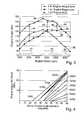
- FIG. 2shows a graph of engine torque against engine speed for a conventional four-cylinder in-line engine, such as that described above, but without supercharging. As can be seen from curve 34 of FIG. 2, the engine can be tuned to provide good power at moderately high engine speeds (“power tune”), but at the expense of low-end torque.
- the enginecan be tuned to give good torque at low and moderate engine speeds (“torque tune”), but at the expense of top-end power. Whilst “power tune” will appeal to the ‘sporting’ driver, it will result in lower levels of satisfaction for the majority of car owners. The requirement to deliver good real world ‘performance feel’ commonly results in an engine torque output as shown in the “torque tune” curve, where torque at high engine speeds has been compromised in order to promote torque output below 3500 rpm. Although engine gearing can be selected to minimize undesirable characteristics, in practice conventional engines are tuned to achieve a compromise.
- a relatively low capacity enginefor example below about 1.8 litres capacity, is tuned to give good torque at high rpm 43 , at the expense of torque at low engine speed 41 and moderate engine speed 42 , as illustrated by curve 38 .
- Thishas the secondary effect of allowing good fuel economy at steady highway cruising speeds through the need to use wider throttle openings to achieve cruising speed.
- curve 40 for supercharger boost (SCB)there is then an increase 44 , 45 , 46 in maximum available engine torque when the driver demands power in excess of that available from a naturally aspirated engine.
- the boostis made available under control of the engine control unit 32 only in a region of low 41 and moderate 42 engine speeds, and is progressively limited to transition smoothly into engine power near or at a peak 48 in the un-boosted torque curve 38 in a region of relatively high engine speed 43 . This is done by progressively limiting the maximum allowable supercharger boost near point 48 .
- the engine control unit 32enables use of the supercharger 10 only in such a way that the engine torque output with the supercharger torque boost peaks 49 in the region of moderate engine speed 42 .
- FIG. 4shows a graph of engine torque supercharger boost against driver throttle angle demand between 0° and 90°.
- the diagonal straight lines on the graphare labelled with engine speed in rpm, between 1250 rpm and 5400 rpm.
- the vertical scalecorresponds to the difference in engine torque in FIG. 3 between the boosted torque curve 40 and the un-boosted torque curve 38 .
- the engine torque supercharger boostis the maximum value shown in FIG. 3 .
- throttle angle demandsdeclines from 90°, so does the engine torque supercharger boost, until this declines to zero boost corresponding to curve 38 of FIG. 3 .
- FIG. 5shows a schematic overview of an electronic control system 50 for controlling the operation of the supercharger 10
- FIG. 6shows a diagram of the control system architecture 60 of the air charge boosting system.
- FIG. 5shows how the engine control unit (ECU) 32 receives the various inputs 116 , 120 - 128 described above, in order to generate various outputs to control the operation of the system.
- One outputis an electronic throttle position (ETP) command 117 , sent to an electronic throttle position controller 217 that controls the throttle 17 .
- the ETP controller 217then sets the position of the throttle 17 accordingly.
- ETPelectronic throttle position
- the ECU 32also sends an EBD speed command 114 to an EBD speed controller 214 that controls the supercharger electric motor 14 .
- the motor 14is controlled to idle at a relatively low and variable speed of up to about 20,000 rpm, which consumes relatively little electric power and which also produces no significant boost pressure.
- the supercharger 10is controlled to idle at a relatively low and variable speed of up to about 20,000 rpm, which consumes relatively little electric power and which also produces no significant boost pressure.
- by idling the supercharger 10 at up to 20,000 rpmit is possible to reduce the spin up time to the rated operating speed of about 60,000 rpm to less than 0.1 s.
- the supercharger 10may not be capable of indefinite operation at its maximum output owing to limitations of the battery 16 storage and alternator 27 charging current, and so the battery state-of-charge (SOC) may restrict operation. Additionally some components of the supercharger 10 such as bearings or motor windings (not shown) may exceed design temperature limits at high operation duty factors. The same considerations mean that the idling speed should also be limited. It may therefore also be necessary to constrain the operation of the supercharger 10 owing to these considerations.
- SOCbattery state-of-charge
- the electrical power supply to the compressor 10may be from the usual vehicle electrical system, it is preferred if the supercharger 10 , during operation above idle speeds, is isolated at least partially from the battery charging system, including the alternator 27 , and run mainly or entirely from the battery 16 .
- the ECU 32calculates allowable operating limits to the operation of the supercharger 10 based on the state of the electrical supply system.
- the state of the electrical supply systemis within an acceptable range
- the supercharger 10is driven using the engine-driven battery charging system and alternator 27
- the battery 16is isolated from the alternator 27 and the supercharger 10 is driven using the battery alone.
- the ECU 32determines the state of the electrical supply system both by monitoring the battery voltage, and by monitoring the capacity utilization of the alternator 27 . If the electrical load on the alternator 27 becomes large enough to saturate the alternator 27 , then electrical supply system voltage will drop, and this can cause a noticeable loss of functionality in other electrical units powered by the vehicle electrical system.
- the supercharger 10 during operation above idle speedsis isolated from the battery charging system and alternator 27 and run from the battery 16 alone.
- the alternator 27is then able to power other vehicle consumer units (CU) 51 , such as lights and electrical accessories, which are therefore isolated from voltage drops that may occur at the battery 16 owing to the large electrical current required by the supercharger 10 , typically between about 150 A and 300 A.
- CUvehicle consumer units
- This switchingis achieved by means of a compressor power source select command 152 sent from the ECU 32 to a relay 52 and switch 53 .
- the ECU 32therefore drives the supercharger 10 using the alternator 27 when the battery state-of-charge is within an acceptable range, and isolates the battery 16 from the alternator 27 and drives the supercharger 10 using the battery 16 alone when the battery state-of-charge is not within an acceptable range.
- the regulated voltage set point of the alternator 27is then controlled by an alternator voltage setpoint command 127 sent from the ECU 32 to the alternator 27 .
- the engine torque outputwill be regulated by the throttle 17 alone. If the supercharger 10 is not required then the supercharger 10 is scheduled to operate at a variable idle speed where no boost is produced. In the event that the supercharger 10 is required then the throttle 17 is scheduled to be fully open and the supercharger speed is scheduled based on the barometric air pressure, the desired manifold air pressure, and the desired mass air flow according to a boost map of supercharger characteristics held within ECU memory (not shown).
- MAPmanifold air pressure
- BAPbarometric air pressure
- derating factors for the supercharger thermal and SOC constraintsare applied as required to generate the final constrained EBD speed command 114 .
- the largest derating factoris applied.
- the calculation of the derating factorsshould be chosen so as to minimise driver perception of the derating, and also make the derated performance predicable for the driver, by avoiding sudden changes.
- the thermal derating calculationinvolves two parts, namely regulation and estimation.
- the estimation part of the calculationis based on the operating conditions of the compressor 10 .
- Critical partstypically include the bearings supporting a compressor shaft and copper windings of the compressor motor.
- the temperatures of these partsare estimated based on the temperatures when the system was turned off, the time it has been off, and the prevailing ambient temperature, for example from the ambient temperature sensor 28 .
- the dynamic temperature estimateaccounts for variations in the air flowing past the supercharger 10 , the thermal inertia of the component parts, and the heat generated in the system from both electrical and mechanical sources.
- the regulation partinvolves predicting for which of the components in the system the design temperatures could be exceeded, based on estimated or measured temperatures. For these, the supercharger operation may be restricted in order to remain within design guidelines. This is achieved by the calibration of ‘soft’ and ‘hard’ limits for each of these components. When the temperature is below the soft limit no action is taken. When the temperature exceeds the soft limit and the temperature at the desired supercharger operation level will result in the hard limit being exceeded in a steady state operation, then some action must be taken to avoid exceeding the hard limit.
- the supercharger 10is progressively derated using a control loop with an output of predetermined percentage degrade factor, until the predicted steady state temperature is equal to the hard limit, at which point the supercharger duty may be sustained. When more than one component of the system may exceed design values, a derating factor is calculated for each and the minimum one selected for use.
- the battery state-of-charge calculationis performed in an analogous manner to the supercharger thermal calculation described above.
- An estimation part of the calculationinvolves a computer model of the storage capacity of the battery 16 . This is used together with the history of the charging and discharging to make an estimate of the current stored charge compared to the maximum available at the prevailing ambient conditions. Additionally the rate of discharge is estimated.
- the regulationis then performed as follows.
- the relay 52is engaged to switch 53 powering of the supercharger 10 to the battery 16 alone, whilst the remaining vehicle system is powered from the alternator 27 .
- a ‘soft’ limitis calibrated for the system state-of-charge (SOC) above which no action need be taken to protect battery charge.
- a ‘hard’ limitis also calibrated below which SOC the battery should not be allowed to fall.
- SOCfalls below the soft limit the system must start to take action so as to achieve a ‘soft landing’ at the hard limit of SOC without sharp falls in engine output due to reduction in power to the supercharger 10 .
- the derate factor for the supercharger 10is increased until the power drawn by the supercharger 10 is equal to the excess generation capacity of the alternator 27 , at which point the relay 52 may be switched so as the alternator now powers the supercharger 10 as well as the remaining vehicle electrical system.
- the supercharger 10 poweris then held at or below a level that does not cause the alternator 27 to fully saturate.
- the electronic control unit 32controls the supercharger 10 at a variable idle speed.
- the idle speedis then controlled in order to reduce the lag time needed for the supercharger 10 to reach an operating speed when the electronic control unit 32 determines that it is likely that the supercharger 10 may soon be needed to boost the air flow to the engine 1 .
- the idle speedis increased when the need for air flow boost becomes more likely, and reduced when the need for air flow boost becomes less likely.
- FIGS. 6 to 13show how the electronic control unit 32 monitors the engine operating parameter(s) and calculates therefrom a likelihood that the engine torque will need to be boosted by the supercharger 10 .
- FIGS. 6 and 8show, respectively, how the history of engine operation and pedal position movement can be calculated, and then used as shown in FIGS. 7 and 8 to generate operating factors which are a measure of the likelihood that supercharger boost will be needed.
- the electronic control unit 32uses the pedal position signal 120 and engine speed signal 121 together with a calibrated table 150 that is based on operating point data, such as that illustrated in FIGS. 3 and 4.
- the output 151 from the table 150is high for engine operating conditions close to the point at which supercharger boost will be needed, and lower for engine operating conditions farther from the point at which supercharger boost will be needed.
- the output 151is fed back 153 and stored with a time delay 154 prior to being attenuated by multiplication 156 an operating point “forget factor” 155 of 0.9, before being combined 157 with the current operating point table output 151 .
- An output 158 from this adaptive loopis passed through a filter which clips 159 the value if necessary so that it falls within a range that represents 0 to 100%.
- the result of this processis an output 160 representing an operating point percentage for the engine 1 .
- the electronic control unit 32converts the output 160 into an engine operating point factor 161 , the use of which will be explained in more detail below.
- FIGS. 8 and 9show a process very similar to that shown in FIGS. 6 and 7 for calculating an accelerator pedal “busyness” factor 181 .
- the electronic control unit 32takes a discrete derivative 163 of the accelerator pedal position signal 120 .
- the absolute value 164 of the derivativeis then a measure of the rate of change of pedal position, which is supplied as an input 165 to a pedal “busyness” calibration table 166 .
- the output 167 from the table 166is high for a busy accelerator pedal, and low for an accelerator pedal that is not moved much or quickly.
- the output 167is fed back 168 and stored with a time delay 169 prior to being attenuated by multiplication 171 a pedal busyness “forget factor” 170 of 0.9, before being combined 172 with the current operating point table output 167 .
- An output 173 from this adaptive loopis passed through a filter which clips 174 the value if necessary so that it falls within a range that represents 0 to 100%.
- the result of this processis an output 180 representing a pedal “busyness” percentage for the pedal operation.
- the electronic control unit 32converts the output 180 into a pedal “busyness” factor 181 , the use of which will be explained in more detail below.
- the electronic control unit 32also calculates any constraints on future operation of the supercharger 10 (hereinafter referenced as the “compressor”).
- FIG. 10shows low and high battery state-of-charge factors 182 , 183 that vary between zero and one, and that are calculated from the battery voltage 116 .
- FIG. 11shows a compressor thermal constraint factor 184 that varies between zero and one, based on a compressor temperature that can either be measured from a temperature sensor (not shown), or calculated based on the history of the compressor operation, and ambient temperatures.
- FIG. 12shows how the various factors 161 , 181 , 182 , 183 and 184 are combined 190 in a fuzzy logic controller 191 .
- the controlleruses the following rules to generate compressor low and high idle speed factors 192 , 193 that vary between zero and one, as shown in FIG. 13 :
- the compressor low idle speed factor 192is an inverted V-shaped function that peaks in the centre of an idle mode of operation 194 and declines to zero at zero idle speed and at the top end of the idle mode of operation 194 .
- the compressor high idle speed factor 193is a similarly shaped function that peaks at a division between the idle mode of operation 194 , and an engine boost mode of operation 195 , and falls to zero the point where the low idle speed factor 192 peaks, and at a point well inside the boost mode of operation 195 .
- the degree of “highness” and “lowness”is then determined by the fuzzy logic, and when related to a low range of idle speeds (0-10,000 rpm) and a high range of idle speeds (10,000-20,000) rpm, is used to generate a compressor idle speed control signal 192 , that is used by the engine control unit 32 to set an appropriate idle speed for the compressor 10 , in order to reduce the lag time taken to bring the compressor 10 up to its operating speed when engine torque boost is required.
- the invention described aboveis applicable to both spark ignition and compression engines.
- the electrically driven compressor 10may be the only inlet air compressor device in the system, or it may be combined with another such device, for example an exhaust gas driven turbocharger device.
- the inventiontherefore provides a convenient and economical electrical pressure boosting device and method for increasing the torque available from an internal combustion engine.
- the electrically driven compressor 10is provided as part of the engine's air intake system, and is fully electronically controllable. Use of such a compressor 10 increases the engine's maximum torque output over portions of its operating range that are significant to the performance perceived by the driver.
- the lag time required to bring the compressor 10 up to operating speed to boost engine torqueis reduced by the determination of an appropriate compressor idling speed, while excess electrical consumption and heating of the compressor while idling is reduced.
- the inventionis compact, and avoids the need to increase excessively the capacity of the vehicle electrical system, or the thermal and mechanical rating of the device, thus allowing benefits in terms of both vehicle performance and overall fuel economy, at a reasonable system cost.
Landscapes
- Engineering & Computer Science (AREA)
- Chemical & Material Sciences (AREA)
- Combustion & Propulsion (AREA)
- Mechanical Engineering (AREA)
- General Engineering & Computer Science (AREA)
- Supercharger (AREA)
- Output Control And Ontrol Of Special Type Engine (AREA)
Abstract
Description
Claims (15)
Applications Claiming Priority (3)
| Application Number | Priority Date | Filing Date | Title |
|---|---|---|---|
| EP01308484AEP1300562A1 (en) | 2001-10-04 | 2001-10-04 | Control system for an internal combustion engine boosted with an electronically controlled compressor |
| EP01308484 | 2001-10-04 | ||
| EP01308484.3 | 2001-10-04 |
Publications (2)
| Publication Number | Publication Date |
|---|---|
| US20030106541A1 US20030106541A1 (en) | 2003-06-12 |
| US6684863B2true US6684863B2 (en) | 2004-02-03 |
Family
ID=8182326
Family Applications (1)
| Application Number | Title | Priority Date | Filing Date |
|---|---|---|---|
| US10/264,628Expired - LifetimeUS6684863B2 (en) | 2001-10-04 | 2002-10-04 | Control system for an internal combustion engine boosted with an electronically controlled compressor |
Country Status (2)
| Country | Link |
|---|---|
| US (1) | US6684863B2 (en) |
| EP (1) | EP1300562A1 (en) |
Cited By (48)
| Publication number | Priority date | Publication date | Assignee | Title |
|---|---|---|---|---|
| US20040086401A1 (en)* | 2002-04-12 | 2004-05-06 | Balestrieri Walter Luigi | Air jet flow system |
| US20040118390A1 (en)* | 2002-07-08 | 2004-06-24 | Honda Giken Kogyo Kabushiki Kaisha | Control system and method and engine control unit for compression ignition internal combustion engine |
| US20040187852A1 (en)* | 2003-03-27 | 2004-09-30 | Nissan Motor Co., Ltd. | Supercharging device for internal combustion engine |
| US20040211204A1 (en)* | 2003-01-08 | 2004-10-28 | Ryo Matsubara | Compressor torque estimate device, engine controller and method of estimating compressor torque |
| US20040250801A1 (en)* | 2003-01-29 | 2004-12-16 | Michael Baeuerle | Method and device for operating a drive unit having an internal combustion engine |
| US20050005920A1 (en)* | 2002-09-23 | 2005-01-13 | Fabiani Sandor C. | Nozzle air injection system for a fuel-injected engine |
| US20050145218A1 (en)* | 2004-01-07 | 2005-07-07 | Rod Radovanovic | Engine tuned for hybrid electric and continuously variable transmission applications |
| US20050161211A1 (en)* | 2002-04-29 | 2005-07-28 | Bergstrom, Inc. | Vehicle air conditioning and heating system providing engine on and engine off operation |
| US20050288148A1 (en)* | 2004-06-28 | 2005-12-29 | Caterpillar Inc. | Continuously variable transmission system with power boost |
| US20060137664A1 (en)* | 2004-12-23 | 2006-06-29 | Mccoy Todd A | Supercharger |
| US20060162333A1 (en)* | 2005-01-26 | 2006-07-27 | Denso Corporation | Engine control system having turbocharger |
| US20070051349A1 (en)* | 2005-09-08 | 2007-03-08 | Mazda Motor Corporation | Control for electrically driven supercharger |
| US20070131206A1 (en)* | 2005-12-08 | 2007-06-14 | John Rollinger | Electronic throttle control supercharging |
| US20070131408A1 (en)* | 2002-04-29 | 2007-06-14 | Bergstrom, Inc. | Vehicle Air Conditioning and Heating System Providing Engine On and Off Operation |
| US20080127939A1 (en)* | 2004-12-03 | 2008-06-05 | Koenigsegg Automotive Ab | Combustion Air Supply Arrangement |
| US20090000298A1 (en)* | 2004-05-07 | 2009-01-01 | Honeywell International Inc. | Method of Operating an Electrically Assisted Turbocharger and a Boosting Device |
| US20110022289A1 (en)* | 2009-07-27 | 2011-01-27 | Ecomotors International, Inc. | Method of controlling an electrically assisted turbocharger |
| US20120234004A1 (en)* | 2011-03-14 | 2012-09-20 | Ford Global Technologies, Llc | Method and device for controlling a starting process of a motor vehicle |
| US8718848B2 (en) | 2011-06-08 | 2014-05-06 | Bendix Commercial Vehicle Systems Llc | State of charge adjusted compressor control |
| US8958971B2 (en) | 2009-07-27 | 2015-02-17 | Ecomotors, Inc. | System and method to control an electronically-controlled turbocharger |
| US20150224864A1 (en)* | 2014-02-12 | 2015-08-13 | Palo Alto Research Center Incorporated | Hybrid vehicle with power boost |
| US20170009678A1 (en)* | 2015-07-07 | 2017-01-12 | GM Global Technology Operations LLC | Drive unit for a motor vehicle, motor vehicle fitted with such a drive unit and computer software product for controlling the drive unit |
| US9676382B2 (en) | 2014-04-17 | 2017-06-13 | Palo Alto Research Center Incorporated | Systems and methods for hybrid vehicles with a high degree of hybridization |
| US9751521B2 (en) | 2014-04-17 | 2017-09-05 | Palo Alto Research Center Incorporated | Control system for hybrid vehicles with high degree of hybridization |
| US9751411B2 (en) | 2012-03-29 | 2017-09-05 | Eaton Corporation | Variable speed hybrid electric supercharger assembly and method of control of vehicle having same |
| US9783024B2 (en) | 2015-03-09 | 2017-10-10 | Bergstrom Inc. | System and method for remotely managing climate control systems of a fleet of vehicles |
| US9796239B2 (en) | 2013-03-13 | 2017-10-24 | Bergstrom Inc. | Air conditioning system utilizing heat recovery ventilation for fresh air supply and climate control |
| US20170328272A1 (en)* | 2015-01-30 | 2017-11-16 | Mitsubishi Heavy Industries, Ltd. | Supercharging system, control device for supercharging system, and method for operating supercharging system |
| US9840130B2 (en) | 2013-03-13 | 2017-12-12 | Bergstrom Inc. | Air conditioning system utilizing thermal capacity from expansion of compressed fluid |
| US9856781B2 (en) | 2011-09-30 | 2018-01-02 | Eaton Corporation | Supercharger assembly with independent superchargers and motor/generator |
| US9874384B2 (en) | 2016-01-13 | 2018-01-23 | Bergstrom, Inc. | Refrigeration system with superheating, sub-cooling and refrigerant charge level control |
| US10006684B2 (en) | 2015-12-10 | 2018-06-26 | Bergstrom, Inc. | Air conditioning system for use in vehicle |
| US10060366B1 (en)* | 2017-06-02 | 2018-08-28 | Ford Global Technologies, Llc | Transient power control method for an engine that includes a compressor |
| US10081226B2 (en) | 2016-08-22 | 2018-09-25 | Bergstrom Inc. | Parallel compressors climate system |
| US10125698B2 (en) | 2013-03-12 | 2018-11-13 | Eaton Intelligent Power Limited | Adaptive state of charge regulation and control of variable speed hybrid electric supercharger assembly for efficient vehicle operation |
| US20180361844A1 (en)* | 2015-12-11 | 2018-12-20 | Volvo Truck Corporation | Device and method for controlling hybrid system |
| US10245916B2 (en) | 2013-11-04 | 2019-04-02 | Bergstrom, Inc. | Low profile air conditioning system |
| US10344668B2 (en) | 2014-01-14 | 2019-07-09 | Eaton Intelligent Power Limited | Boost system including hybrid drive supercharger with compact configuration |
| US10369863B2 (en) | 2016-09-30 | 2019-08-06 | Bergstrom, Inc. | Refrigerant liquid-gas separator with electronics cooling |
| US10562372B2 (en) | 2016-09-02 | 2020-02-18 | Bergstrom, Inc. | Systems and methods for starting-up a vehicular air-conditioning system |
| US10589598B2 (en) | 2016-03-09 | 2020-03-17 | Bergstrom, Inc. | Integrated condenser and compressor system |
| US10675948B2 (en) | 2016-09-29 | 2020-06-09 | Bergstrom, Inc. | Systems and methods for controlling a vehicle HVAC system |
| CN111271173A (en)* | 2020-02-11 | 2020-06-12 | 吉利汽车研究院(宁波)有限公司 | An electronic supercharger control method and control system for a vehicle |
| US10724772B2 (en) | 2016-09-30 | 2020-07-28 | Bergstrom, Inc. | Refrigerant liquid-gas separator having an integrated check valve |
| US20210062776A1 (en)* | 2019-08-26 | 2021-03-04 | Ford Global Technologies, Llc | Systems and methods for controlling boost during an engine cold start |
| US11420496B2 (en) | 2018-04-02 | 2022-08-23 | Bergstrom, Inc. | Integrated vehicular system for conditioning air and heating water |
| US11448441B2 (en) | 2017-07-27 | 2022-09-20 | Bergstrom, Inc. | Refrigerant system for cooling electronics |
| US12420616B2 (en) | 2016-08-22 | 2025-09-23 | Bergstrom, Inc. | Multi-compressor oil migration mitigation climate system |
Families Citing this family (14)
| Publication number | Priority date | Publication date | Assignee | Title |
|---|---|---|---|---|
| DE10024390C2 (en)* | 2000-05-17 | 2002-05-16 | Compact Dynamics Gmbh | Turbo compressor for a piston internal combustion engine |
| US7668704B2 (en)* | 2006-01-27 | 2010-02-23 | Ricardo, Inc. | Apparatus and method for compressor and turbine performance simulation |
| US8204702B2 (en)* | 2007-10-26 | 2012-06-19 | GM Global Technology Operations LLC | Method for estimating battery life in a hybrid powertrain |
| US20100263639A1 (en)* | 2009-04-20 | 2010-10-21 | Ford Global Technologies, Llc | Engine Control Method and System |
| US8374742B2 (en) | 2011-09-16 | 2013-02-12 | Ford Global Technologies, Llc | Turbocharger launch control |
| DE102015223635B4 (en)* | 2015-11-30 | 2025-01-16 | Volkswagen Aktiengesellschaft | Method for controlling an aerodynamic compressor for an internal combustion engine and aerodynamic compressor for an internal combustion engine |
| FR3045106B1 (en)* | 2015-12-11 | 2019-08-30 | Renault S.A.S | METHOD FOR MANAGING THE USE OF AN ELECTRIC COMPRESSOR IN A VEHICLE WITH AN AUTOMATIC BOX |
| DE102016200982A1 (en)* | 2016-01-25 | 2017-07-27 | Volkswagen Aktiengesellschaft | Method and control device for operating a drive device |
| US10161303B2 (en)* | 2016-07-07 | 2018-12-25 | Ford Global Technologies, Llc | Systems and methods for generating auxiliary torque |
| IT201700021386A1 (en)* | 2017-02-24 | 2018-08-24 | Samuele Labanca | MOTOR WITH OVERFLOW CONTROL SYSTEM |
| DE102019202707A1 (en)* | 2019-02-28 | 2020-09-17 | Volkswagen Aktiengesellschaft | Method for operating an internal combustion engine, control device and electrically powered charging device |
| JP7180482B2 (en)* | 2019-03-22 | 2022-11-30 | トヨタ自動車株式会社 | hybrid vehicle |
| DE102019205044A1 (en)* | 2019-04-09 | 2020-11-05 | Volkswagen Aktiengesellschaft | Method and devices for operating an internal combustion engine with a supercharging system |
| CN112253308B (en)* | 2020-01-14 | 2021-11-09 | 长城汽车股份有限公司 | Turbo lag power-assisted compensation method, device and equipment and hybrid vehicle |
Citations (13)
| Publication number | Priority date | Publication date | Assignee | Title |
|---|---|---|---|---|
| US4617895A (en) | 1984-05-17 | 1986-10-21 | Nippondenso Co., Ltd. | Anti-knocking control in internal combustion engine |
| US4757686A (en) | 1985-08-30 | 1988-07-19 | Isuzu Motors Limited | Control system for supercharger in internal combustion engine |
| US4774811A (en) | 1986-02-10 | 1988-10-04 | Isuzu Motors Limited | Apparatus for recovering thermal energy from engine |
| EP0397316A1 (en) | 1989-05-10 | 1990-11-14 | Isuzu Motors Limited | Power supply system for turbocharger with rotary electric machine |
| US5022375A (en)* | 1988-03-31 | 1991-06-11 | Mazda Motor Corporation | Supercharging device of an engine |
| US5291871A (en)* | 1991-01-18 | 1994-03-08 | Aisin Seiki Kabushiki Kaisha | Supercharged diesel engine |
| JPH06219188A (en) | 1992-10-23 | 1994-08-09 | Mazda Motor Corp | Control device for power train |
| US5426589A (en) | 1991-09-17 | 1995-06-20 | Honda Giken Kogyo Kabushiki Kaisha | Method of and apparatus for limiting electrical loads on an electric vehicle |
| JPH10159577A (en) | 1996-12-02 | 1998-06-16 | Hitachi Ltd | Control device for electric motor driven supercharger |
| DE19712850A1 (en) | 1997-03-27 | 1998-10-01 | Bosch Gmbh Robert | Device for controlling a diverter valve |
| WO2002010565A1 (en) | 2000-07-28 | 2002-02-07 | Visteon Global Technologies, Inc. | Internal combustion engine supercharger |
| GB2365070A (en)* | 2000-07-28 | 2002-02-13 | Visteon Global Tech Inc | Control of electrically-driven supercharger for i.c. engines |
| EP1300559A1 (en)* | 2001-10-03 | 2003-04-09 | Visteon Global Technologies, Inc. | Control system for an internal combustion engine boosted with an electronically controlled pressure charging device |
- 2001
- 2001-10-04EPEP01308484Apatent/EP1300562A1/ennot_activeWithdrawn
- 2002
- 2002-10-04USUS10/264,628patent/US6684863B2/ennot_activeExpired - Lifetime
Patent Citations (13)
| Publication number | Priority date | Publication date | Assignee | Title |
|---|---|---|---|---|
| US4617895A (en) | 1984-05-17 | 1986-10-21 | Nippondenso Co., Ltd. | Anti-knocking control in internal combustion engine |
| US4757686A (en) | 1985-08-30 | 1988-07-19 | Isuzu Motors Limited | Control system for supercharger in internal combustion engine |
| US4774811A (en) | 1986-02-10 | 1988-10-04 | Isuzu Motors Limited | Apparatus for recovering thermal energy from engine |
| US5022375A (en)* | 1988-03-31 | 1991-06-11 | Mazda Motor Corporation | Supercharging device of an engine |
| EP0397316A1 (en) | 1989-05-10 | 1990-11-14 | Isuzu Motors Limited | Power supply system for turbocharger with rotary electric machine |
| US5291871A (en)* | 1991-01-18 | 1994-03-08 | Aisin Seiki Kabushiki Kaisha | Supercharged diesel engine |
| US5426589A (en) | 1991-09-17 | 1995-06-20 | Honda Giken Kogyo Kabushiki Kaisha | Method of and apparatus for limiting electrical loads on an electric vehicle |
| JPH06219188A (en) | 1992-10-23 | 1994-08-09 | Mazda Motor Corp | Control device for power train |
| JPH10159577A (en) | 1996-12-02 | 1998-06-16 | Hitachi Ltd | Control device for electric motor driven supercharger |
| DE19712850A1 (en) | 1997-03-27 | 1998-10-01 | Bosch Gmbh Robert | Device for controlling a diverter valve |
| WO2002010565A1 (en) | 2000-07-28 | 2002-02-07 | Visteon Global Technologies, Inc. | Internal combustion engine supercharger |
| GB2365070A (en)* | 2000-07-28 | 2002-02-13 | Visteon Global Tech Inc | Control of electrically-driven supercharger for i.c. engines |
| EP1300559A1 (en)* | 2001-10-03 | 2003-04-09 | Visteon Global Technologies, Inc. | Control system for an internal combustion engine boosted with an electronically controlled pressure charging device |
Cited By (94)
| Publication number | Priority date | Publication date | Assignee | Title |
|---|---|---|---|---|
| US20040086401A1 (en)* | 2002-04-12 | 2004-05-06 | Balestrieri Walter Luigi | Air jet flow system |
| US8453722B2 (en) | 2002-04-29 | 2013-06-04 | Bergstrom, Inc. | Vehicle air conditioning and heating system providing engine on and engine off operation |
| US20090301702A1 (en)* | 2002-04-29 | 2009-12-10 | Bergstrom, Inc. | Vehicle Air Conditioning and Heating Method Providing Engine On and Engine Off Operation |
| US7591143B2 (en)* | 2002-04-29 | 2009-09-22 | Bergstrom, Inc. | Vehicle air conditioning and heating system providing engine on and engine off operation |
| US7454922B2 (en) | 2002-04-29 | 2008-11-25 | Bergstrom, Inc. | Vehicle air conditioning and heating method providing engine on and engine off operation |
| US7591303B2 (en) | 2002-04-29 | 2009-09-22 | Bergstrom, Inc. | Vehicle air conditioning and heating method providing engine on and engine off operation |
| US20070131408A1 (en)* | 2002-04-29 | 2007-06-14 | Bergstrom, Inc. | Vehicle Air Conditioning and Heating System Providing Engine On and Off Operation |
| US20060102333A1 (en)* | 2002-04-29 | 2006-05-18 | Bergstrom, Inc. | Vehicle air conditioning and heating method providing engine on and engine off operation |
| US20060151164A1 (en)* | 2002-04-29 | 2006-07-13 | Bergstrom, Inc. | Vehicle air conditioning and heating method providing engine on and engine off operation |
| US20050161211A1 (en)* | 2002-04-29 | 2005-07-28 | Bergstrom, Inc. | Vehicle air conditioning and heating system providing engine on and engine off operation |
| US9487063B2 (en) | 2002-04-29 | 2016-11-08 | Bergstrom, Inc. | Vehicle air conditioning and heating system providing engine on and engine off operation |
| US20060151163A1 (en)* | 2002-04-29 | 2006-07-13 | Bergstrom, Inc | Vehicle air conditioning and heating method providing engine on and engine off operation |
| US9694651B2 (en) | 2002-04-29 | 2017-07-04 | Bergstrom, Inc. | Vehicle air conditioning and heating system providing engine on and off operation |
| US7448227B2 (en) | 2002-04-29 | 2008-11-11 | Bergstrom, Inc. | Vehicle air conditioning and heating method providing engine on and engine off operation |
| US6817349B2 (en)* | 2002-07-08 | 2004-11-16 | Honda Giken Kogyo Kabushiki Kaisha | Control system and method and engine control unit for compression ignition internal combustion engine |
| US20040118390A1 (en)* | 2002-07-08 | 2004-06-24 | Honda Giken Kogyo Kabushiki Kaisha | Control system and method and engine control unit for compression ignition internal combustion engine |
| US20050005920A1 (en)* | 2002-09-23 | 2005-01-13 | Fabiani Sandor C. | Nozzle air injection system for a fuel-injected engine |
| US20040211204A1 (en)* | 2003-01-08 | 2004-10-28 | Ryo Matsubara | Compressor torque estimate device, engine controller and method of estimating compressor torque |
| US6910344B2 (en)* | 2003-01-08 | 2005-06-28 | Kabushiki Kaisha Toyota Jidoshokki | Compressor torque estimate device, engine controller and method of estimating compressor torque |
| US20040250801A1 (en)* | 2003-01-29 | 2004-12-16 | Michael Baeuerle | Method and device for operating a drive unit having an internal combustion engine |
| US6945221B2 (en)* | 2003-01-29 | 2005-09-20 | Robert Bosch Gmbh | Method and device for operating a drive unit having an internal combustion engine |
| US6922995B2 (en)* | 2003-03-27 | 2005-08-02 | Nissan Motor Co., Ltd. | Supercharging device for internal combustion engine |
| US20040187852A1 (en)* | 2003-03-27 | 2004-09-30 | Nissan Motor Co., Ltd. | Supercharging device for internal combustion engine |
| US7487757B2 (en)* | 2004-01-07 | 2009-02-10 | Cummins, Inc. | Engine tuned for hybrid electric and continuously variable transmission applications |
| US20050145218A1 (en)* | 2004-01-07 | 2005-07-07 | Rod Radovanovic | Engine tuned for hybrid electric and continuously variable transmission applications |
| US8205450B2 (en)* | 2004-05-07 | 2012-06-26 | Honeywell International Inc. | Method of operating an electrically assisted turbocharger and a boosting device |
| US20090000298A1 (en)* | 2004-05-07 | 2009-01-01 | Honeywell International Inc. | Method of Operating an Electrically Assisted Turbocharger and a Boosting Device |
| US20050288148A1 (en)* | 2004-06-28 | 2005-12-29 | Caterpillar Inc. | Continuously variable transmission system with power boost |
| US7469761B2 (en) | 2004-06-28 | 2008-12-30 | Caterpillar Inc. | Continuously variable transmission system with power boost |
| US20080127939A1 (en)* | 2004-12-03 | 2008-06-05 | Koenigsegg Automotive Ab | Combustion Air Supply Arrangement |
| US7958871B2 (en)* | 2004-12-03 | 2011-06-14 | Koenigsegg Automotive Ab | Combustion air supply arrangement |
| US20060137664A1 (en)* | 2004-12-23 | 2006-06-29 | Mccoy Todd A | Supercharger |
| US7503175B2 (en)* | 2005-01-26 | 2009-03-17 | Denso Corporation | Engine control system having turbocharger |
| US20060162333A1 (en)* | 2005-01-26 | 2006-07-27 | Denso Corporation | Engine control system having turbocharger |
| US7628015B2 (en)* | 2005-09-08 | 2009-12-08 | Mazda Motor Corporation | Control for electrically driven supercharger |
| EP1762711A1 (en) | 2005-09-08 | 2007-03-14 | Mazda Motor Corporation | Control for electrically driven supercharger |
| US20070051349A1 (en)* | 2005-09-08 | 2007-03-08 | Mazda Motor Corporation | Control for electrically driven supercharger |
| US20070131206A1 (en)* | 2005-12-08 | 2007-06-14 | John Rollinger | Electronic throttle control supercharging |
| US7748366B2 (en)* | 2005-12-08 | 2010-07-06 | Ford Global Technologies, Llc | Electronic throttle control supercharging |
| US8958971B2 (en) | 2009-07-27 | 2015-02-17 | Ecomotors, Inc. | System and method to control an electronically-controlled turbocharger |
| US20110022289A1 (en)* | 2009-07-27 | 2011-01-27 | Ecomotors International, Inc. | Method of controlling an electrically assisted turbocharger |
| US9303570B2 (en)* | 2011-03-14 | 2016-04-05 | Ford Global Technologies, Llc | Method and device for controlling a starting process of a motor vehicle |
| US20120234004A1 (en)* | 2011-03-14 | 2012-09-20 | Ford Global Technologies, Llc | Method and device for controlling a starting process of a motor vehicle |
| US8718848B2 (en) | 2011-06-08 | 2014-05-06 | Bendix Commercial Vehicle Systems Llc | State of charge adjusted compressor control |
| US9856781B2 (en) | 2011-09-30 | 2018-01-02 | Eaton Corporation | Supercharger assembly with independent superchargers and motor/generator |
| US9751411B2 (en) | 2012-03-29 | 2017-09-05 | Eaton Corporation | Variable speed hybrid electric supercharger assembly and method of control of vehicle having same |
| US10125698B2 (en) | 2013-03-12 | 2018-11-13 | Eaton Intelligent Power Limited | Adaptive state of charge regulation and control of variable speed hybrid electric supercharger assembly for efficient vehicle operation |
| US10934951B2 (en) | 2013-03-12 | 2021-03-02 | Eaton Intelligent Power Limited | Adaptive state of charge regulation and control of variable speed hybrid electric supercharger assembly for efficient vehicle operation |
| US10414243B2 (en) | 2013-03-13 | 2019-09-17 | Bergstrom, Inc. | Vehicular ventilation module for use with a vehicular HVAC system |
| US9796239B2 (en) | 2013-03-13 | 2017-10-24 | Bergstrom Inc. | Air conditioning system utilizing heat recovery ventilation for fresh air supply and climate control |
| US9840130B2 (en) | 2013-03-13 | 2017-12-12 | Bergstrom Inc. | Air conditioning system utilizing thermal capacity from expansion of compressed fluid |
| US10245916B2 (en) | 2013-11-04 | 2019-04-02 | Bergstrom, Inc. | Low profile air conditioning system |
| US10344668B2 (en) | 2014-01-14 | 2019-07-09 | Eaton Intelligent Power Limited | Boost system including hybrid drive supercharger with compact configuration |
| US9789756B2 (en)* | 2014-02-12 | 2017-10-17 | Palo Alto Research Center Incorporated | Hybrid vehicle with power boost |
| US20150224864A1 (en)* | 2014-02-12 | 2015-08-13 | Palo Alto Research Center Incorporated | Hybrid vehicle with power boost |
| US9676382B2 (en) | 2014-04-17 | 2017-06-13 | Palo Alto Research Center Incorporated | Systems and methods for hybrid vehicles with a high degree of hybridization |
| US10625729B2 (en) | 2014-04-17 | 2020-04-21 | Palo Alto Research Center Incorporated | Control system for hybrid vehicles with high degree of hybridization |
| US9751521B2 (en) | 2014-04-17 | 2017-09-05 | Palo Alto Research Center Incorporated | Control system for hybrid vehicles with high degree of hybridization |
| US10753272B2 (en)* | 2015-01-30 | 2020-08-25 | Mitsubishi Heavy Industries, Ltd. | Engine supercharger for maintaining a battery charge |
| US20170328272A1 (en)* | 2015-01-30 | 2017-11-16 | Mitsubishi Heavy Industries, Ltd. | Supercharging system, control device for supercharging system, and method for operating supercharging system |
| US10967709B2 (en) | 2015-03-09 | 2021-04-06 | Bergstrom, Inc. | Graphical user interfaces for remotely managing climate control systems of a fleet of vehicles |
| US11780292B2 (en) | 2015-03-09 | 2023-10-10 | Bergstrom, Inc. | Graphical user interfaces for remotely managing climate control systems of a fleet of vehicles |
| US9783024B2 (en) | 2015-03-09 | 2017-10-10 | Bergstrom Inc. | System and method for remotely managing climate control systems of a fleet of vehicles |
| US12304281B2 (en) | 2015-03-09 | 2025-05-20 | Bergstrom, Inc. | Systems and methods of managing a power source of a vehicle |
| US10427496B2 (en) | 2015-03-09 | 2019-10-01 | Bergstrom, Inc. | System and method for remotely managing climate control systems of a fleet of vehicles |
| US20170009678A1 (en)* | 2015-07-07 | 2017-01-12 | GM Global Technology Operations LLC | Drive unit for a motor vehicle, motor vehicle fitted with such a drive unit and computer software product for controlling the drive unit |
| US10145318B2 (en)* | 2015-07-07 | 2018-12-04 | GM Global Technology Operations LLC | Drive unit for a motor vehicle, motor vehicle fitted with such a drive unit and computer software product for controlling the drive unit |
| US10006684B2 (en) | 2015-12-10 | 2018-06-26 | Bergstrom, Inc. | Air conditioning system for use in vehicle |
| US20180361844A1 (en)* | 2015-12-11 | 2018-12-20 | Volvo Truck Corporation | Device and method for controlling hybrid system |
| US10974584B2 (en)* | 2015-12-16 | 2021-04-13 | Volvo Truck Corporation | Device and method for controlling hybrid system |
| US10527332B2 (en) | 2016-01-13 | 2020-01-07 | Bergstrom, Inc. | Refrigeration system with superheating, sub-cooling and refrigerant charge level control |
| US9874384B2 (en) | 2016-01-13 | 2018-01-23 | Bergstrom, Inc. | Refrigeration system with superheating, sub-cooling and refrigerant charge level control |
| US10589598B2 (en) | 2016-03-09 | 2020-03-17 | Bergstrom, Inc. | Integrated condenser and compressor system |
| US12420616B2 (en) | 2016-08-22 | 2025-09-23 | Bergstrom, Inc. | Multi-compressor oil migration mitigation climate system |
| US10703173B2 (en) | 2016-08-22 | 2020-07-07 | Bergstrom, Inc. | Multi-compressor climate system |
| US11479086B2 (en) | 2016-08-22 | 2022-10-25 | Bergstrom, Inc. | Multi-compressor climate system |
| US10081226B2 (en) | 2016-08-22 | 2018-09-25 | Bergstrom Inc. | Parallel compressors climate system |
| US10562372B2 (en) | 2016-09-02 | 2020-02-18 | Bergstrom, Inc. | Systems and methods for starting-up a vehicular air-conditioning system |
| US10675948B2 (en) | 2016-09-29 | 2020-06-09 | Bergstrom, Inc. | Systems and methods for controlling a vehicle HVAC system |
| US11712946B2 (en) | 2016-09-29 | 2023-08-01 | Bergstrom, Inc. | Systems and methods for controlling a vehicle HVAC system |
| US11241939B2 (en) | 2016-09-29 | 2022-02-08 | Bergstrom, Inc. | Systems and methods for controlling a vehicle HVAC system |
| US12240295B2 (en) | 2016-09-29 | 2025-03-04 | Bergstrom, Inc. | Systems and methods for controlling a vehicle HVAC system |
| US10724772B2 (en) | 2016-09-30 | 2020-07-28 | Bergstrom, Inc. | Refrigerant liquid-gas separator having an integrated check valve |
| US11512883B2 (en) | 2016-09-30 | 2022-11-29 | Bergstrom, Inc. | Refrigerant liquid-gas separator |
| US10369863B2 (en) | 2016-09-30 | 2019-08-06 | Bergstrom, Inc. | Refrigerant liquid-gas separator with electronics cooling |
| US10060366B1 (en)* | 2017-06-02 | 2018-08-28 | Ford Global Technologies, Llc | Transient power control method for an engine that includes a compressor |
| US11448441B2 (en) | 2017-07-27 | 2022-09-20 | Bergstrom, Inc. | Refrigerant system for cooling electronics |
| US12065019B2 (en) | 2017-07-27 | 2024-08-20 | Bergstrom, Inc. | Refrigerant system for cooling electronics |
| US11420496B2 (en) | 2018-04-02 | 2022-08-23 | Bergstrom, Inc. | Integrated vehicular system for conditioning air and heating water |
| US11919364B2 (en) | 2018-04-02 | 2024-03-05 | Bergstrom, Inc. | Integrated vehicular system for conditioning air and heating water |
| US10975790B2 (en)* | 2019-08-26 | 2021-04-13 | Ford Global Technologies, Llc | Systems and methods for controlling boost during an engine cold start |
| US20210062776A1 (en)* | 2019-08-26 | 2021-03-04 | Ford Global Technologies, Llc | Systems and methods for controlling boost during an engine cold start |
| CN111271173B (en)* | 2020-02-11 | 2021-01-15 | 吉利汽车研究院(宁波)有限公司 | Control method and control system for electronic supercharger of vehicle |
| CN111271173A (en)* | 2020-02-11 | 2020-06-12 | 吉利汽车研究院(宁波)有限公司 | An electronic supercharger control method and control system for a vehicle |
Also Published As
| Publication number | Publication date |
|---|---|
| US20030106541A1 (en) | 2003-06-12 |
| EP1300562A1 (en) | 2003-04-09 |
Similar Documents
| Publication | Publication Date | Title |
|---|---|---|
| US6684863B2 (en) | Control system for an internal combustion engine boosted with an electronically controlled compressor | |
| CN106246393B (en) | The control device of internal combustion engine | |
| US9169790B2 (en) | Method for controlling the operation of a compressor | |
| US8122986B2 (en) | Powertrain and method for controlling a powertrain in a vehicle | |
| US9341145B2 (en) | Supercharged turbocompound hybrid engine apparatus | |
| US6739135B2 (en) | Control system for an internal combustion engine boosted with an electronically controlled pressure charging device | |
| US7210296B2 (en) | Method and device for controlling an electrically driven charger | |
| US6751957B2 (en) | Control system for an internal combustion engine boosted with an electronically controlled pressure charging device | |
| US6823853B2 (en) | Thermal modeling of a switched reluctance motor | |
| US20060196183A1 (en) | Supercharging assist control system and method | |
| US20040093867A1 (en) | Control device for turbocharger with electric motor and control method of same | |
| JPH07150990A (en) | Method and equipment for controlling driving output of car | |
| RU154667U1 (en) | ENGINE TORQUE DISTRIBUTION SYSTEM | |
| US20080053091A1 (en) | Turbocharging Device and Control Method for Controlling the Turbocharging Device | |
| JP2014163320A (en) | Control device | |
| CN111417772B (en) | Method and device for controlling internal combustion engine for vehicle | |
| EP1300570B1 (en) | Control system for an internal combustion engine boosted with an electronically controlled pressure charging device | |
| EP1300560B1 (en) | Control system for an internal combustion engine boosted with an electronically controlled pressure charging device | |
| JP5631465B1 (en) | Electric supercharger control device and electric supercharger control method | |
| EP1350937A2 (en) | Energy regeneration control system and method for an internal combustion engine | |
| EP3613963B1 (en) | Internal combustion engine control method and internal combustion engine control device | |
| JP2016138502A (en) | Cylinder deactivation control device for internal combustion engine | |
| CN113847149A (en) | Method and device for operating an internal combustion engine with an electrically assisted exhaust gas-driven supercharging device | |
| JP2006097559A (en) | Supercharging pressure control device for engine with supercharger | |
| JP2005113690A (en) | Control device for internal combustion engine for vehicle |
Legal Events
| Date | Code | Title | Description |
|---|---|---|---|
| AS | Assignment | Owner name:VISTEON GLOBAL TECHNOLOGIES, INC., MICHIGAN Free format text:ASSIGNMENT OF ASSIGNORS INTEREST;ASSIGNORS:DIXON, JON;WIJETUNGE, ROSHAN SENA;REEL/FRAME:013739/0699;SIGNING DATES FROM 20030103 TO 20030119 | |
| STCF | Information on status: patent grant | Free format text:PATENTED CASE | |
| CC | Certificate of correction | ||
| FPAY | Fee payment | Year of fee payment:4 | |
| AS | Assignment | Owner name:CONTROLLED POWER TECHNOLOGIES LIMITED, UNITED KING Free format text:ASSIGNMENT OF ASSIGNORS INTEREST;ASSIGNORS:VISTEON GLOBAL TECHNOLOGIES, INC.;VISTEON UK LIMITED;REEL/FRAME:020638/0082 Effective date:20071228 | |
| AS | Assignment | Owner name:VISTEON UK LIMITED, UNITED KINGDOM Free format text:LICENSE;ASSIGNOR:CONTROLLED POWER TECHNOLOGIES LIMITED;REEL/FRAME:020617/0900 Effective date:20071228 Owner name:VISTEON GLOBAL TECHNOLOGIES, INC., MICHIGAN Free format text:LICENSE;ASSIGNOR:CONTROLLED POWER TECHNOLOGIES LIMITED;REEL/FRAME:020617/0900 Effective date:20071228 | |
| AS | Assignment | Owner name:JPMORGAN CHASE BANK, TEXAS Free format text:SECURITY INTEREST;ASSIGNOR:VISTEON GLOBAL TECHNOLOGIES, INC.;REEL/FRAME:022368/0001 Effective date:20060814 Owner name:JPMORGAN CHASE BANK,TEXAS Free format text:SECURITY INTEREST;ASSIGNOR:VISTEON GLOBAL TECHNOLOGIES, INC.;REEL/FRAME:022368/0001 Effective date:20060814 | |
| FPAY | Fee payment | Year of fee payment:8 | |
| AS | Assignment | Owner name:VALEO AIR MANAGEMENT UK LIMITED, UNITED KINGDOM Free format text:CHANGE OF NAME;ASSIGNOR:CONTROLLED POWER TECHNOLOGIES LIMITED;REEL/FRAME:028440/0195 Effective date:20111213 | |
| FPAY | Fee payment | Year of fee payment:12 |