US6684710B2 - Device for measuring pressure comprising a membrane moulded into a cassette - Google Patents
Device for measuring pressure comprising a membrane moulded into a cassetteDownload PDFInfo
- Publication number
- US6684710B2 US6684710B2US10/004,857US485701AUS6684710B2US 6684710 B2US6684710 B2US 6684710B2US 485701 AUS485701 AUS 485701AUS 6684710 B2US6684710 B2US 6684710B2
- Authority
- US
- United States
- Prior art keywords
- closure element
- pressure
- blood
- rigid wall
- measurement section
- Prior art date
- Legal status (The legal status is an assumption and is not a legal conclusion. Google has not performed a legal analysis and makes no representation as to the accuracy of the status listed.)
- Expired - Lifetime
Links
- 239000012528membraneSubstances0.000titledescription42
- 239000008280bloodSubstances0.000claimsabstractdescription40
- 210000004369bloodAnatomy0.000claimsabstractdescription40
- 238000009530blood pressure measurementMethods0.000claimsabstractdescription40
- 230000036772blood pressureEffects0.000claimsabstractdescription21
- 239000012080ambient airSubstances0.000claimsabstractdescription12
- 230000000694effectsEffects0.000claimsabstractdescription8
- 239000008188pelletSubstances0.000claimsdescription17
- 238000006073displacement reactionMethods0.000claimsdescription8
- 238000000465mouldingMethods0.000claimsdescription5
- 230000002093peripheral effectEffects0.000claimsdescription5
- 230000009467reductionEffects0.000claimsdescription5
- 230000000295complement effectEffects0.000claimsdescription3
- 238000003754machiningMethods0.000claimsdescription3
- 238000005259measurementMethods0.000description9
- 239000003570airSubstances0.000description6
- 239000002184metalSubstances0.000description5
- 238000000502dialysisMethods0.000description4
- 229920001296polysiloxanePolymers0.000description3
- 230000008901benefitEffects0.000description2
- 230000007423decreaseEffects0.000description2
- 230000006866deteriorationEffects0.000description2
- 238000004519manufacturing processMethods0.000description2
- 239000000463materialSubstances0.000description2
- 238000000034methodMethods0.000description2
- 238000005086pumpingMethods0.000description2
- 244000043261Hevea brasiliensisSpecies0.000description1
- 239000004743PolypropyleneSubstances0.000description1
- 230000017531blood circulationEffects0.000description1
- 230000008878couplingEffects0.000description1
- 238000010168coupling processMethods0.000description1
- 238000005859coupling reactionMethods0.000description1
- 230000005489elastic deformationEffects0.000description1
- 230000036571hydrationEffects0.000description1
- 238000006703hydration reactionMethods0.000description1
- 230000001771impaired effectEffects0.000description1
- 230000006872improvementEffects0.000description1
- 238000001746injection mouldingMethods0.000description1
- 238000012544monitoring processMethods0.000description1
- 229920003052natural elastomerPolymers0.000description1
- 229920001194natural rubberPolymers0.000description1
- 229920000515polycarbonatePolymers0.000description1
- 239000004417polycarbonateSubstances0.000description1
- -1polypropylenePolymers0.000description1
- 229920001155polypropylenePolymers0.000description1
- 230000008569processEffects0.000description1
- 230000002459sustained effectEffects0.000description1
Images


Classifications
- A—HUMAN NECESSITIES
- A61—MEDICAL OR VETERINARY SCIENCE; HYGIENE
- A61M—DEVICES FOR INTRODUCING MEDIA INTO, OR ONTO, THE BODY; DEVICES FOR TRANSDUCING BODY MEDIA OR FOR TAKING MEDIA FROM THE BODY; DEVICES FOR PRODUCING OR ENDING SLEEP OR STUPOR
- A61M1/00—Suction or pumping devices for medical purposes; Devices for carrying-off, for treatment of, or for carrying-over, body-liquids; Drainage systems
- A61M1/36—Other treatment of blood in a by-pass of the natural circulatory system, e.g. temperature adaptation, irradiation ; Extra-corporeal blood circuits
- A61M1/3621—Extra-corporeal blood circuits
- A61M1/3639—Blood pressure control, pressure transducers specially adapted therefor
- A—HUMAN NECESSITIES
- A61—MEDICAL OR VETERINARY SCIENCE; HYGIENE
- A61M—DEVICES FOR INTRODUCING MEDIA INTO, OR ONTO, THE BODY; DEVICES FOR TRANSDUCING BODY MEDIA OR FOR TAKING MEDIA FROM THE BODY; DEVICES FOR PRODUCING OR ENDING SLEEP OR STUPOR
- A61M1/00—Suction or pumping devices for medical purposes; Devices for carrying-off, for treatment of, or for carrying-over, body-liquids; Drainage systems
- A61M1/36—Other treatment of blood in a by-pass of the natural circulatory system, e.g. temperature adaptation, irradiation ; Extra-corporeal blood circuits
- A61M1/3621—Extra-corporeal blood circuits
- A61M1/3622—Extra-corporeal blood circuits with a cassette forming partially or totally the blood circuit
- A61M1/36224—Extra-corporeal blood circuits with a cassette forming partially or totally the blood circuit with sensing means or components thereof
- A—HUMAN NECESSITIES
- A61—MEDICAL OR VETERINARY SCIENCE; HYGIENE
- A61M—DEVICES FOR INTRODUCING MEDIA INTO, OR ONTO, THE BODY; DEVICES FOR TRANSDUCING BODY MEDIA OR FOR TAKING MEDIA FROM THE BODY; DEVICES FOR PRODUCING OR ENDING SLEEP OR STUPOR
- A61M1/00—Suction or pumping devices for medical purposes; Devices for carrying-off, for treatment of, or for carrying-over, body-liquids; Drainage systems
- A61M1/36—Other treatment of blood in a by-pass of the natural circulatory system, e.g. temperature adaptation, irradiation ; Extra-corporeal blood circuits
- A61M1/3621—Extra-corporeal blood circuits
- A61M1/3622—Extra-corporeal blood circuits with a cassette forming partially or totally the blood circuit
- A61M1/36226—Constructional details of cassettes, e.g. specific details on material or shape
- A—HUMAN NECESSITIES
- A61—MEDICAL OR VETERINARY SCIENCE; HYGIENE
- A61M—DEVICES FOR INTRODUCING MEDIA INTO, OR ONTO, THE BODY; DEVICES FOR TRANSDUCING BODY MEDIA OR FOR TAKING MEDIA FROM THE BODY; DEVICES FOR PRODUCING OR ENDING SLEEP OR STUPOR
- A61M1/00—Suction or pumping devices for medical purposes; Devices for carrying-off, for treatment of, or for carrying-over, body-liquids; Drainage systems
- A61M1/36—Other treatment of blood in a by-pass of the natural circulatory system, e.g. temperature adaptation, irradiation ; Extra-corporeal blood circuits
- A61M1/3621—Extra-corporeal blood circuits
- A61M1/3639—Blood pressure control, pressure transducers specially adapted therefor
- A61M1/3641—Pressure isolators
- G—PHYSICS
- G01—MEASURING; TESTING
- G01L—MEASURING FORCE, STRESS, TORQUE, WORK, MECHANICAL POWER, MECHANICAL EFFICIENCY, OR FLUID PRESSURE
- G01L19/00—Details of, or accessories for, apparatus for measuring steady or quasi-steady pressure of a fluent medium insofar as such details or accessories are not special to particular types of pressure gauges
- G01L19/0007—Fluidic connecting means
- G01L19/0023—Fluidic connecting means for flowthrough systems having a flexible pressure transmitting element
- A—HUMAN NECESSITIES
- A61—MEDICAL OR VETERINARY SCIENCE; HYGIENE
- A61M—DEVICES FOR INTRODUCING MEDIA INTO, OR ONTO, THE BODY; DEVICES FOR TRANSDUCING BODY MEDIA OR FOR TAKING MEDIA FROM THE BODY; DEVICES FOR PRODUCING OR ENDING SLEEP OR STUPOR
- A61M1/00—Suction or pumping devices for medical purposes; Devices for carrying-off, for treatment of, or for carrying-over, body-liquids; Drainage systems
- A61M1/36—Other treatment of blood in a by-pass of the natural circulatory system, e.g. temperature adaptation, irradiation ; Extra-corporeal blood circuits
- A61M1/3621—Extra-corporeal blood circuits
- A61M1/3622—Extra-corporeal blood circuits with a cassette forming partially or totally the blood circuit
- A61M1/36225—Extra-corporeal blood circuits with a cassette forming partially or totally the blood circuit with blood pumping means or components thereof
- A—HUMAN NECESSITIES
- A61—MEDICAL OR VETERINARY SCIENCE; HYGIENE
- A61M—DEVICES FOR INTRODUCING MEDIA INTO, OR ONTO, THE BODY; DEVICES FOR TRANSDUCING BODY MEDIA OR FOR TAKING MEDIA FROM THE BODY; DEVICES FOR PRODUCING OR ENDING SLEEP OR STUPOR
- A61M1/00—Suction or pumping devices for medical purposes; Devices for carrying-off, for treatment of, or for carrying-over, body-liquids; Drainage systems
- A61M1/36—Other treatment of blood in a by-pass of the natural circulatory system, e.g. temperature adaptation, irradiation ; Extra-corporeal blood circuits
- A61M1/3621—Extra-corporeal blood circuits
- A61M1/3622—Extra-corporeal blood circuits with a cassette forming partially or totally the blood circuit
- A61M1/36226—Constructional details of cassettes, e.g. specific details on material or shape
- A61M1/362261—Constructional details of cassettes, e.g. specific details on material or shape at least one cassette surface or portion thereof being flexible, e.g. the cassette having a rigid base portion with preformed channels and being covered with a foil
- A—HUMAN NECESSITIES
- A61—MEDICAL OR VETERINARY SCIENCE; HYGIENE
- A61M—DEVICES FOR INTRODUCING MEDIA INTO, OR ONTO, THE BODY; DEVICES FOR TRANSDUCING BODY MEDIA OR FOR TAKING MEDIA FROM THE BODY; DEVICES FOR PRODUCING OR ENDING SLEEP OR STUPOR
- A61M2205/00—General characteristics of the apparatus
- A61M2205/12—General characteristics of the apparatus with interchangeable cassettes forming partially or totally the fluid circuit
Definitions
- the present inventionrelates to a device for measuring the pressure of blood.
- the present inventionrelates to a device for measuring the pressure of blood, which is used in an extra corporeal blood treatment device in which the blood is taken from a patient in order to be treated then reintroduced into the body of the patient (especially for the purpose of carrying out dialysis) by means of an extracorporeal blood circuit comprising pipes and including at least one section for measuring the pressure of blood flowing in a pipe.
- a known type of pressure measurement sectioncomprises, in a substantially rigid wall, a hole which is sealed by a closure element, the internal face of which is in contact with the blood and the external face of which is in contact with the ambient air, it being possible to elastically deform or displace the closure element overall along a deformation or displacement axis which is substantially orthogonal to its general plane, under the effect of the blood pressure; a portion of the external face of the closure element, in its rest state, is in direct or indirect contact with a load sensor which can measure the force applied axially to the internal face of the closure element by the pressure of the blood, in order to calculate therefrom the value of this pressure.
- this type of extracorporeal blood treatment devicecomprises a circuit part which is made from a casing, or cassette, of the disposable type, incorporating pipes which are connected to the extracorporeal blood circuit.
- the pressure measurement sectionmay be an attached module which is mounted in an associated housing of the casing.
- the casingis mounted on a support apparatus which comprises, for example, sensors, display means, pumping means, a control interface, an electronic control unit, etc.
- the blood pressuremust be measured without contact between the measurement member and the blood.
- a pressure measurement section 10 in a pipe 12comprises a measurement chamber 14 in which a membrane 16 , or diaphragm, separates the blood flowing in the pipe 12 from the air contained in a compartment 18 .
- the membrane 16can be deformed along a deformation axis A—A which is orthogonal to its general plane, so that it is displaced axially according to the pressure of the blood in the pipe 12 .
- the air compartment 18is sealed shut when the pressure measurement section 10 is mounted on a support apparatus 20 .
- the support apparatus 20comprises a sensor 22 which directly measures the pressure in the air compartment 18 .
- the membrane 16When the blood pressure changes, the membrane 16 is axially displaced to an equilibrium position in which the pressure on both sides of the membrane 16 is equal.
- the pressure measured by the sensor 22 in the air compartment 18is therefore equal to the pressure of the blood in the pipe 12 .
- this first pressure measurement systemmakes it possible to measure, on the one hand, so-called “positive” blood pressures, that is to say, blood pressures which are greater than a reference pressure, in this case atmospheric pressure, and, on the other hand, so-called “negative” blood pressures, that is to say blood pressures which are less than the reference pressure.
- This measurement systemoperates correctly provided that there are no leaks in the air compartment 18 , otherwise the membrane 16 is displaced right up to its end stop and it no longer carries out the function of transmitting pressure.
- the seal of the air compartment 18 during mounting of the pressure measurement section 10 on the support apparatus 20is a weak point of the measurement system.
- the sealmay be impaired during use of the measurement system.
- the pressure measurement section 10forms a compartment 24 containing the blood and one wall 26 of which comprises a hole 28 which is sealed by a flexible membrane 30 .
- the external face of the central part of the flexible membrane 30is in contact with a load transmitter 32 which is inserted between the membrane 30 and a load sensor 34 .
- the load sensor 34makes it possible to measure the forces applied to the internal face of the membrane 30 because of the effect of the blood pressure in the compartment 24 , where the blood pressure is greater than the ambient air pressure.
- Fis the force measured by the load sensor 34
- F 0is the force measured in the rest state, that is to say, in the absence of a pressure gradient between the two sides (internal and external faces) of the membrane 30
- S ais the active area or active surface area of the membrane 30 .
- the active surface area S a of the membrane 30is equivalent to an area intermediate between the total area of the internal face of the membrane 30 in contact with the blood and the area of contact between the membrane 30 and the load transmitter 32 .
- This measurement systemallows positive pressures to be measured but it does not allow negative pressures to be measured.
- This systemhas therefore been adapted to measure negative pressure.
- the membrane 30is secured in axial displacement to the load transmitter 32 .
- the membranehas a metal disc 36 on its external face and the load transmitter 32 has a magnet 38 at its axial end facing the membrane 30 .
- the magnetic attraction exerted by the magnet 38 on the metal disc 36makes it possible to secure the membrane 30 in axial displacement to the load transmitter 32 .
- the membrane 30exerts a force which pushes axially against the load transmitter 32 .
- This device for securing the membrane 30 to the load transmitter 32is expensive since it requires a special membrane 30 fitted with a metal disc 36 and a special load transmitter 32 fitted with a magnet 38 .
- the metal disc 36must have a large area in order to allow effective magnetic coupling.
- the membrane 30is subject to a significant jolt when the metal disc 36 “sticks” to the magnet 38 of the load transmitter 32 , which may impair its mechanical characteristics.
- the known measurement systemsrequire an attached membrane 30 , which is made from a material different to that of the pressure measurement section 10 .
- the two pressure measurement systemsgenerally use flexible membranes 30 made of silicone.
- An attached membrane 30is relatively complex to mount since the membranes 30 must completely seal the hole 28 of the associated wall 26 , which involves high manufacturing and assembly costs for the pressure measurement system.
- the purpose of the inventionis to remedy these drawbacks and to provide a pressure measurement system which is simpler than the existing systems.
- the inventionproposes a device for measuring the pressure of blood in a pipe of an extracorporeal blood circuit, comprising a pressure measurement section having a substantially rigid wall including a hole which is sealed by a closure element, the internal face of which is in contact with the blood and the external face of which is in contact with the ambient air, it being possible for the closure element to be elastically deformed or displaced overall along a deformation or displacement axis which is substantially orthogonal to its general plane, under the effect of the blood pressure, the pressure measurement section being designed to engage with a load sensor so that a portion of the external face of the closure element is, in its rest state, in direct or indirect contact with a load sensor which can measure the force applied axially on the internal face of the closure element by the blood pressure, in order to calculate therefrom the value of this pressure, characterized in that the closure element is made in a single piece with the associated rigid wall of the pressure measurement section.
- the closure element according to the inventionmakes it possible to overcome specific problems connected with the use of flexible membranes.
- the membraneAfter a given period, the membrane therefore remains deformed in spite of a return to the initial conditions corresponding to its rest state.
- This phenomenon of creepis particularly significant for large diameter membranes, that is to say membranes whose diameter is greater than 25 millimeters, made of silicone or of natural rubber, which lose about eight percent of their elasticity in one hour.
- the temperature and the hydration of the membranemay also cause deterioration of its properties, particularly its elasticity.
- the closure elementincludes a region of lower resistance to elastic axial deformation, compared to the rigid wall;
- the region of lower resistance to elastic axial deformationcircumscribes the portion of the external face of the closure element which, in its rest state, is in direct or indirect contact with the load sensor;
- the closure elementcomprises a substantially rigid central pellet which is delimited by a thinned peripheral annular region of axial thickness less than the axial thickness of the rigid wall in order to form an elastically deformable region;
- the thinned regionis made by machining the rigid wall associated with the closure element
- closure elementis made by moulding with the associated rigid wall
- the profile of the thinned regionis substantially undulating
- a load transmitteris inserted axially between the external face of the closure element and the load sensor
- the load sensoror the load transmitter, applies an initial axial pretensioning force to the closure element, in its rest state, for the purpose of making it possible, in particular, to measure a pressure less than the pressure of the ambient air or to measure a reduction in pressure with respect to a reference pressure;
- the external face of the closure elementcomprises a gripping member, or a member that can be gripped, which engages with a complementary member of the load transmitter, so as to secure the closure element in axial displacement with the load transmitter, for the purpose of making it possible, in particular, to measure a pressure less than the pressure of the ambient air or to measure a reduction in pressure with respect to a reference pressure;
- the gripping member, or the member which can be gripped, of the closure elementis made in a single piece with the pellet;
- the pressure measurement sectionis an attached module which is mounted in an associated housing of the casing;
- closure elementis substantially disc-shaped
- At least one portion of the rigid wall bordering the holebears axially towards the outside against a support plate.
- FIG. 1is a schematic view in cross section which shows a first type of pressure measurement system according to the prior art
- FIG. 2is similar to that of FIG. 1 which shows a second type of pressure measurement system according to the prior art
- FIG. 3is a view similar to that of FIG. 1 which shows an improvement to the pressure measurement system of FIG. 2 according to the prior art;
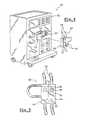
- FIG. 4is a perspective view which shows schematically an extracorporeal blood treatment device made according to the teachings of the invention.
- FIG. 5is a top view which shows schematically the cassette of the device of FIG. 4;
- FIG. 6is a view similar to that of FIG. 1 which shows a pressure measurement section of the device of FIG. 4;
- FIG. 7is a view similar to that of FIG. 1 which shows a variant of the pressure measurement section of FIG. 6 for the purpose of measuring negative pressure.
- FIG. 4shows an extracorporeal blood treatment device 40 for the purpose of carrying out dialysis.
- This device 40is designed to take blood from a patient, to treat it for the purpose of carrying out dialysis, then to reintroduce it into the body of the patient.
- This device 40comprises an extracorporeal blood circuit 42 (shown partially here) comprising pipes 44 and including at least one section 46 for measuring the pressure of the blood flowing in a pipe 44 .
- part of the extracorporeal blood circuit 42is made up of a substantially parallelepipedal casing 48 , also called a cassette, which, in its thickness, contains pipes 44 for the flow of blood, which, in its thickness are connected to the other pipes 44 of the extracorporeal blood circuit 42 .
- the cassette 48comprises two similar pressure measurement sections 46 which are contained in its thickness.
- the cassette 48is designed to be mounted on a support plate 50 of a dialysis apparatus 52 , which comprises, in particular, pumping means 54 to make the blood flow in the circuit 42 and means for monitoring certain parameters of the circuit 42 , in particular, load sensors 56 which engage with the sections 46 to monitor the pressure in the pipes 44 of the circuit 42 .
- the cassette 48is made, for example, by moulding, of polycarbonate or polypropylene or from another suitable material.
- the pressure measurement section 46which is shown schematically in FIG. 6, in this case forms a substantially parallelepipedal compartment 58 which is inserted between two branches 60 , 62 of a pipe 44 , and which is, for example, moulded with the cassette 48 .
- the lattermay be a module attached to the cassette 48 .
- a substantially rigid wall, or main wall 64 , of the pressure measurement section 46comprises a hole 66 which is sealed by a closure element 68 , the internal face 70 of which is in contact with the blood and the external face 72 of which is in contact with the ambient air.
- the main wall 64 of the pressure measurement section 46is designed to be placed facing the support plate 50 , so that the closure element 68 is facing a load sensor 56 .
- FIG. 5shows the cassette 48 seen from the side of the main wall 64 .
- the closure element 68is made in a single piece with the main wall 64 of the section 46 , in this case by moulding.
- the closure element 68comprises a disc-shaped substantially rigid central pellet 74 which is delimited by a thinned peripheral annular region 76 with an axial thickness less than the axial thickness of the main wall 64 , so as to form an elastically deformable region.
- the load sensor 56may therefore measure the force applied axially to the internal face 70 of the pellet 74 by the blood pressure, in order to calculate therefrom the value of this pressure.
- the central pellet 74has the same thickness as the thinned region 76 , such that it is also elastically deformable along the axis A—A.
- the measurement section 46is axially positioned with respect to the load transmitter 78 such that the load transmitter 78 applies an initial pretensioning force F 0 , in the absence of a pressure gradient between the internal face 70 and the external face 72 of the closure element 68 , so that contact between the closure element 68 and the load transmitter 78 can be guaranteed.
- the main wall 64 of the pressure measurement section 46which borders the hole 66 , bears axially towards the outside against the support plate 50 , such that, in the case of positive pressure, the main wall 64 cannot be axially deformed towards the outside.
- the profile of the thinned region 76is substantially undulating.
- the axial thickness of the thinned region 76must, in this case, be compatible with the injection-moulding technique which makes it possible to produce the cassette 48 by moulding. This axial thickness is, for example, about 0.2 millimeters.
- closure element 68is that its elasticity varies very little over time.
- These small variations in elasticitymay be corrected, for example, by a process of automatic correction of the measurements made by the load sensor 56 .
- the active surface area S a of the closure element 68 according to the inventionis slightly greater than the area of contact between the pellet 74 and the load transmitter 78 .
- This active surface area S adepends, in particular, on the geometry of the thinned region 76 .
- the load sensor 56is of the strain gauge type.
- the thinned region 76is made by machining the main wall 64 .
- the closure element 68 according to the inventionmakes it possible to measure positive pressure in a way similar to a conventional closure element of the flexible-membrane type.
- the operating principleis similar to that which is used to measure positive pressures, but a larger initial pretensioning force F 0 is applied so that the resultant force measured by the load sensor 56 is always positive, within the range of pressures measured.
- This principle of measuring a negative pressureis possible only if the pretensioning force F 0 does not vary during operation, or if it is possible to dynamically correct the variation in the pretensioning force F 0 as a function of the temperature or the creep, if there is any.
- FIG. 7shows an alternative embodiment of the invention which makes it possible to measure negative pressures without applying a large pretensioning force F 0 .
- a member 80 which can be grippedis moulded into the external face 72 of the central pellet 74 .
- FIG. 7shows schematically, by way of example, a member 80 which can be gripped and which comprises an axial rod 82 equipped with transverse notches 84 .
- the notches 84engage with complementary jaws 86 of the load transmitter 78 , so as to secure the pellet 74 in axial displacement with the load transmitter 78 .
- the central pellet 74tends to be displaced axially towards the inside of the compartment 58 , under the effect of atmospheric pressure.
- the central pellet 74therefore exerts an axial pulling force on the load transmitter 78 , which makes it possible for the load sensor 56 to measure a force which corresponds to the drop in blood pressure inside the compartment 58 .
- this alternative embodimentmakes it possible to measure any pressure drop, with respect to a reference pressure, even if the blood pressure remains greater than atmospheric pressure.
Landscapes
- Health & Medical Sciences (AREA)
- Heart & Thoracic Surgery (AREA)
- Vascular Medicine (AREA)
- Life Sciences & Earth Sciences (AREA)
- General Health & Medical Sciences (AREA)
- Anesthesiology (AREA)
- Biomedical Technology (AREA)
- Hematology (AREA)
- Cardiology (AREA)
- Animal Behavior & Ethology (AREA)
- Engineering & Computer Science (AREA)
- Public Health (AREA)
- Veterinary Medicine (AREA)
- Physics & Mathematics (AREA)
- General Physics & Mathematics (AREA)
- External Artificial Organs (AREA)
- Measuring Fluid Pressure (AREA)
- Separation Using Semi-Permeable Membranes (AREA)
Abstract
Description

Claims (16)
Applications Claiming Priority (2)
| Application Number | Priority Date | Filing Date | Title |
|---|---|---|---|
| FR0015968 | 2000-12-08 | ||
| FR0015968AFR2817754B1 (en) | 2000-12-08 | 2000-12-08 | DEVICE FOR PRESSURE MEASUREMENT COMPRISING A MEMBRANE MOLDED IN A CASSETTE |
Publications (2)
| Publication Number | Publication Date |
|---|---|
| US20020107468A1 US20020107468A1 (en) | 2002-08-08 |
| US6684710B2true US6684710B2 (en) | 2004-02-03 |
Family
ID=8857403
Family Applications (1)
| Application Number | Title | Priority Date | Filing Date |
|---|---|---|---|
| US10/004,857Expired - LifetimeUS6684710B2 (en) | 2000-12-08 | 2001-12-07 | Device for measuring pressure comprising a membrane moulded into a cassette |
Country Status (9)
| Country | Link |
|---|---|
| US (1) | US6684710B2 (en) |
| EP (1) | EP1213035B1 (en) |
| JP (1) | JP4083420B2 (en) |
| AT (1) | ATE390942T1 (en) |
| AU (1) | AU779201B2 (en) |
| CA (1) | CA2363634C (en) |
| DE (1) | DE60133447T2 (en) |
| ES (1) | ES2305042T3 (en) |
| FR (1) | FR2817754B1 (en) |
Cited By (13)
| Publication number | Priority date | Publication date | Assignee | Title |
|---|---|---|---|---|
| US20060275907A1 (en)* | 2003-05-09 | 2006-12-07 | Cgs Sensortechnik Gmbh | Device for measuring pressure |
| US20080245153A1 (en)* | 2007-04-03 | 2008-10-09 | Invendo Medical Gmbh | Pressure gauge |
| US20100292628A1 (en)* | 2009-05-13 | 2010-11-18 | Haemonetics Corporation | Pressure Monitoring within a Fluid Cassette |
| US9328969B2 (en) | 2011-10-07 | 2016-05-03 | Outset Medical, Inc. | Heat exchange fluid purification for dialysis system |
| US9402945B2 (en) | 2014-04-29 | 2016-08-02 | Outset Medical, Inc. | Dialysis system and methods |
| US9545469B2 (en) | 2009-12-05 | 2017-01-17 | Outset Medical, Inc. | Dialysis system with ultrafiltration control |
| US9808567B2 (en) | 2012-12-14 | 2017-11-07 | Gambro Lundia Ab | Diaphragm repositioning for pressure pod using position sensing |
| US10422712B2 (en)* | 2017-08-18 | 2019-09-24 | Surpass Industry Co., Ltd. | Pressure detection device and pressure sensor |
| US11534537B2 (en) | 2016-08-19 | 2022-12-27 | Outset Medical, Inc. | Peritoneal dialysis system and methods |
| US11724013B2 (en) | 2010-06-07 | 2023-08-15 | Outset Medical, Inc. | Fluid purification system |
| US20230400373A1 (en)* | 2022-06-14 | 2023-12-14 | Honeywell International Inc. | Pre-formed solid as coupling mechanism in media-isolated pressure sensors |
| US12201762B2 (en) | 2018-08-23 | 2025-01-21 | Outset Medical, Inc. | Dialysis system and methods |
| US12390565B2 (en) | 2019-04-30 | 2025-08-19 | Outset Medical, Inc. | Dialysis systems and methods |
Families Citing this family (30)
| Publication number | Priority date | Publication date | Assignee | Title |
|---|---|---|---|---|
| US7238164B2 (en)* | 2002-07-19 | 2007-07-03 | Baxter International Inc. | Systems, methods and apparatuses for pumping cassette-based therapies |
| ATE503174T1 (en) | 2003-01-30 | 2011-04-15 | Jms Co Ltd | PRESSURE DETECTOR |
| JP4742549B2 (en)* | 2004-09-17 | 2011-08-10 | ニプロ株式会社 | Blood purification equipment |
| JP2006130063A (en)* | 2004-11-05 | 2006-05-25 | Nipro Corp | Blood purification apparatus |
| JP4734942B2 (en)* | 2005-02-01 | 2011-07-27 | 株式会社ジェイ・エム・エス | Pressure detector |
| JP4549229B2 (en)* | 2005-05-11 | 2010-09-22 | Junken Medical株式会社 | Blood purification system |
| JP2008259553A (en)* | 2007-04-10 | 2008-10-30 | Asahi Kasei Kuraray Medical Co Ltd | Pressure sensor |
| EP2155287B1 (en) | 2007-05-15 | 2017-10-04 | Gambro Lundia AB | Pressure sensing device and use of the same in a connecting structure |
| WO2009096851A1 (en)* | 2008-01-28 | 2009-08-06 | Milux Holding Sa | A drainage device comprising a filter cleaning device |
| JP5356833B2 (en)* | 2009-01-08 | 2013-12-04 | 日機装株式会社 | Pressure detector |
| JP5426269B2 (en)* | 2009-08-04 | 2014-02-26 | 日機装株式会社 | Blood circuit and blood purification apparatus having the same |
| US9241641B2 (en) | 2012-07-20 | 2016-01-26 | Acist Medical Systems, Inc. | Fiber optic sensor assembly for sensor delivery device |
| CN103830781A (en)* | 2012-11-27 | 2014-06-04 | 深圳先进技术研究院 | Multifunctional blood purification therapeutic equipment and control method thereof |
| US9220834B2 (en)* | 2012-12-20 | 2015-12-29 | Acist Medical Systems, Inc. | Pressure sensing in medical injection systems |
| US10912875B2 (en)* | 2014-10-09 | 2021-02-09 | Fresenius Medical Care Holdings, Inc. | Sensing negative pressure with a pressure transducer |
| EP3318290B1 (en)* | 2016-11-03 | 2020-04-22 | This AG | Cassette for ophthalmological apparatus |
| KR101968324B1 (en)* | 2016-12-12 | 2019-04-12 | 주식회사 미래엔지니어링 | Diaphragm assembly and pressure tranmitter system comprising the same |
| US11458240B2 (en) | 2017-09-28 | 2022-10-04 | Terumo Kabushiki Kaisha | Biological component collection system with internal pressure sensor and method |
| EP3687597A2 (en) | 2017-09-28 | 2020-08-05 | Terumo Kabushiki Kaisha | Biological component collection device, biological component collection system, and circuit internal pressure acquisition method |
| CN107875507B (en)* | 2017-12-28 | 2018-12-21 | 北京灵泽医药技术开发有限公司 | Two-way mechanism and detection device, system, extrusion infusing pipeline and fluid control devices |
| JP6483874B1 (en)* | 2018-01-18 | 2019-03-13 | 日機装株式会社 | Pressure detector adjustment device |
| WO2019188504A1 (en)* | 2018-03-26 | 2019-10-03 | Terumo Kabushiki Kaisha | Biological component collection system and flow path internal pressure acquisition method |
| JP7404360B2 (en) | 2018-10-31 | 2023-12-25 | アシスト・メディカル・システムズ,インコーポレイテッド | fluid pressure sensor protection |
| WO2020090542A1 (en)* | 2018-11-01 | 2020-05-07 | Terumo Kabushiki Kaisha | Biological component collection system and circuit internal pressure acquisition method |
| EP3873558B1 (en) | 2018-11-01 | 2023-03-08 | TERUMO Kabushiki Kaisha | Biological component collection system and circuit internal pressure acquisition method |
| JP7355813B2 (en)* | 2018-11-01 | 2023-10-03 | テルモ株式会社 | Biological component collection system and method of operating the biological component collection system |
| EP3921639A4 (en)* | 2019-02-06 | 2022-03-16 | Siemens Healthcare Diagnostics, Inc. | LIQUID SENSOR ARRANGEMENT, DEVICE AND METHOD |
| CN111494744B (en)* | 2020-04-21 | 2023-03-07 | 深圳汉诺医疗创新技术有限公司 | Integrated box of detecting element and pipeline |
| CN117295533A (en)* | 2021-05-06 | 2023-12-26 | 巴克斯特国际公司 | Automated peritoneal dialysis system including enhanced pressure sensing features |
| CN118252989B (en)* | 2024-03-26 | 2024-12-20 | 山东中保康医疗器具有限公司 | A monitoring box switch control module and a blood separator based on the monitoring box |
Citations (10)
| Publication number | Priority date | Publication date | Assignee | Title |
|---|---|---|---|---|
| US4657490A (en)* | 1985-03-27 | 1987-04-14 | Quest Medical, Inc. | Infusion pump with disposable cassette |
| US4951509A (en)* | 1988-08-22 | 1990-08-28 | Nissho Corporation | Fluid-pressure detector |
| US5098262A (en)* | 1990-12-28 | 1992-03-24 | Abbott Laboratories | Solution pumping system with compressible pump cassette |
| US5108367A (en)* | 1984-02-08 | 1992-04-28 | Abbott Laboratories | Pressure responsive multiple input infusion system |
| US5215450A (en) | 1991-03-14 | 1993-06-01 | Yehuda Tamari | Innovative pumping system for peristaltic pumps |
| US5392653A (en) | 1992-06-03 | 1995-02-28 | Allergan, Inc. | Pressure transducer magnetically-coupled interface complementing minimal diaphragm movement during operation |
| US5399171A (en) | 1991-06-10 | 1995-03-21 | Baxter International Inc. | Intravenous metering monitoring device |
| US5429485A (en)* | 1992-12-18 | 1995-07-04 | Minnesota Mining And Manufacturing Company | Plural inlet pumping cassette with integral manifold |
| US5588816A (en)* | 1993-05-26 | 1996-12-31 | Quest Medical, Inc. | Disposable cassette for cardioplegia delivery system |
| WO1999013926A2 (en) | 1997-09-12 | 1999-03-25 | Cobe Laboratories, Inc. | Extracorporeal blood processing system |
Family Cites Families (1)
| Publication number | Priority date | Publication date | Assignee | Title |
|---|---|---|---|---|
| US6171253B1 (en)* | 1999-05-04 | 2001-01-09 | Apex Medical, Inc. | Flat tube pressure sensor |
- 2000
- 2000-12-08FRFR0015968Apatent/FR2817754B1/ennot_activeExpired - Fee Related
- 2001
- 2001-11-22CACA002363634Apatent/CA2363634C/ennot_activeExpired - Fee Related
- 2001-11-22AUAU93388/01Apatent/AU779201B2/ennot_activeCeased
- 2001-12-03EPEP01403095Apatent/EP1213035B1/ennot_activeExpired - Lifetime
- 2001-12-03ESES01403095Tpatent/ES2305042T3/ennot_activeExpired - Lifetime
- 2001-12-03DEDE60133447Tpatent/DE60133447T2/ennot_activeExpired - Lifetime
- 2001-12-03ATAT01403095Tpatent/ATE390942T1/ennot_activeIP Right Cessation
- 2001-12-07USUS10/004,857patent/US6684710B2/ennot_activeExpired - Lifetime
- 2001-12-07JPJP2001374329Apatent/JP4083420B2/ennot_activeExpired - Fee Related
Patent Citations (10)
| Publication number | Priority date | Publication date | Assignee | Title |
|---|---|---|---|---|
| US5108367A (en)* | 1984-02-08 | 1992-04-28 | Abbott Laboratories | Pressure responsive multiple input infusion system |
| US4657490A (en)* | 1985-03-27 | 1987-04-14 | Quest Medical, Inc. | Infusion pump with disposable cassette |
| US4951509A (en)* | 1988-08-22 | 1990-08-28 | Nissho Corporation | Fluid-pressure detector |
| US5098262A (en)* | 1990-12-28 | 1992-03-24 | Abbott Laboratories | Solution pumping system with compressible pump cassette |
| US5215450A (en) | 1991-03-14 | 1993-06-01 | Yehuda Tamari | Innovative pumping system for peristaltic pumps |
| US5399171A (en) | 1991-06-10 | 1995-03-21 | Baxter International Inc. | Intravenous metering monitoring device |
| US5392653A (en) | 1992-06-03 | 1995-02-28 | Allergan, Inc. | Pressure transducer magnetically-coupled interface complementing minimal diaphragm movement during operation |
| US5429485A (en)* | 1992-12-18 | 1995-07-04 | Minnesota Mining And Manufacturing Company | Plural inlet pumping cassette with integral manifold |
| US5588816A (en)* | 1993-05-26 | 1996-12-31 | Quest Medical, Inc. | Disposable cassette for cardioplegia delivery system |
| WO1999013926A2 (en) | 1997-09-12 | 1999-03-25 | Cobe Laboratories, Inc. | Extracorporeal blood processing system |
Cited By (21)
| Publication number | Priority date | Publication date | Assignee | Title |
|---|---|---|---|---|
| US7803628B2 (en)* | 2003-05-09 | 2010-09-28 | Mhm Harzbecher Medizintechnik Gmbh | Device for measuring pressure |
| US20060275907A1 (en)* | 2003-05-09 | 2006-12-07 | Cgs Sensortechnik Gmbh | Device for measuring pressure |
| US20080245153A1 (en)* | 2007-04-03 | 2008-10-09 | Invendo Medical Gmbh | Pressure gauge |
| US7823457B2 (en) | 2007-04-03 | 2010-11-02 | Invendo Medical Gmbh | Pressure gauge |
| US20100292628A1 (en)* | 2009-05-13 | 2010-11-18 | Haemonetics Corporation | Pressure Monitoring within a Fluid Cassette |
| US8591448B2 (en)* | 2009-05-13 | 2013-11-26 | Haemonetics Corporation | Pressure monitoring within a fluid cassette |
| US9545469B2 (en) | 2009-12-05 | 2017-01-17 | Outset Medical, Inc. | Dialysis system with ultrafiltration control |
| US11724013B2 (en) | 2010-06-07 | 2023-08-15 | Outset Medical, Inc. | Fluid purification system |
| US9328969B2 (en) | 2011-10-07 | 2016-05-03 | Outset Medical, Inc. | Heat exchange fluid purification for dialysis system |
| US9808567B2 (en) | 2012-12-14 | 2017-11-07 | Gambro Lundia Ab | Diaphragm repositioning for pressure pod using position sensing |
| US9504777B2 (en) | 2014-04-29 | 2016-11-29 | Outset Medical, Inc. | Dialysis system and methods |
| US9402945B2 (en) | 2014-04-29 | 2016-08-02 | Outset Medical, Inc. | Dialysis system and methods |
| US9579440B2 (en) | 2014-04-29 | 2017-02-28 | Outset Medical, Inc. | Dialysis system and methods |
| US11305040B2 (en) | 2014-04-29 | 2022-04-19 | Outset Medical, Inc. | Dialysis system and methods |
| US11534537B2 (en) | 2016-08-19 | 2022-12-27 | Outset Medical, Inc. | Peritoneal dialysis system and methods |
| US11951241B2 (en) | 2016-08-19 | 2024-04-09 | Outset Medical, Inc. | Peritoneal dialysis system and methods |
| US10422712B2 (en)* | 2017-08-18 | 2019-09-24 | Surpass Industry Co., Ltd. | Pressure detection device and pressure sensor |
| US12201762B2 (en) | 2018-08-23 | 2025-01-21 | Outset Medical, Inc. | Dialysis system and methods |
| US12390565B2 (en) | 2019-04-30 | 2025-08-19 | Outset Medical, Inc. | Dialysis systems and methods |
| US20230400373A1 (en)* | 2022-06-14 | 2023-12-14 | Honeywell International Inc. | Pre-formed solid as coupling mechanism in media-isolated pressure sensors |
| US12181358B2 (en)* | 2022-06-14 | 2024-12-31 | Honeywell International Inc. | Pre-formed solid as coupling mechanism in media-isolated pressure sensors |
Also Published As
| Publication number | Publication date |
|---|---|
| AU9338801A (en) | 2002-06-13 |
| FR2817754A1 (en) | 2002-06-14 |
| DE60133447T2 (en) | 2009-09-03 |
| CA2363634A1 (en) | 2002-06-08 |
| JP2002233570A (en) | 2002-08-20 |
| FR2817754B1 (en) | 2003-09-12 |
| US20020107468A1 (en) | 2002-08-08 |
| JP4083420B2 (en) | 2008-04-30 |
| DE60133447D1 (en) | 2008-05-15 |
| AU779201B2 (en) | 2005-01-13 |
| EP1213035A1 (en) | 2002-06-12 |
| EP1213035B1 (en) | 2008-04-02 |
| ATE390942T1 (en) | 2008-04-15 |
| CA2363634C (en) | 2009-01-20 |
| ES2305042T3 (en) | 2008-11-01 |
Similar Documents
| Publication | Publication Date | Title |
|---|---|---|
| US6684710B2 (en) | Device for measuring pressure comprising a membrane moulded into a cassette | |
| US6649046B2 (en) | Device for measuring negative pressures in an extracorporeal blood circuit | |
| EP1591767B1 (en) | Pressure detector | |
| EP0643823B1 (en) | Pressure transducer interface | |
| US5644285A (en) | Pressure transducer with media isolation | |
| CA2363922C (en) | Pressure measurement device comprising a motorized load sensor and a process for controlling the device | |
| US6272930B1 (en) | Tube assembly including a pressure measuring device | |
| EP3990084B1 (en) | Intermittent urinary catheter assembly comprising sensor element | |
| JP3870917B2 (en) | Temperature sensor integrated pressure sensor device and temperature sensor fixing method thereof | |
| KR100965966B1 (en) | Surgical system with non-invasive flow sensor | |
| WO2007110946A1 (en) | Pressure detection device | |
| KR20130139957A (en) | Pressure monitoring system for infusion pumps | |
| CA2281301A1 (en) | Monolithic silicon intra-ocular pressure sensor and method therefor | |
| JP6185550B2 (en) | Device for supplying and measuring fluids for medical purposes | |
| US7722557B2 (en) | Blood purification apparatus | |
| JP3915474B2 (en) | Pressure detector | |
| JP4734942B2 (en) | Pressure detector | |
| CN218923434U (en) | Nutrient pump | |
| HK1077633B (en) | Pressure detector and pressure detecting method | |
| JPH08184516A (en) | Semiconductor pressure sensor |
Legal Events
| Date | Code | Title | Description |
|---|---|---|---|
| AS | Assignment | Owner name:HOSPAL INTERNATIONAL MARKETING MANAGEMENT, FRANCE Free format text:ASSIGNMENT OF ASSIGNORS INTEREST;ASSIGNORS:CHEVALLET, JACQUES;COURT, THIERRY;MERCIER, GUY;REEL/FRAME:012977/0462;SIGNING DATES FROM 20020325 TO 20020328 | |
| FEPP | Fee payment procedure | Free format text:PAYOR NUMBER ASSIGNED (ORIGINAL EVENT CODE: ASPN); ENTITY STATUS OF PATENT OWNER: LARGE ENTITY | |
| STCF | Information on status: patent grant | Free format text:PATENTED CASE | |
| AS | Assignment | Owner name:CITICORP TRUSTEE COMPANY LIMITED, AS SECURITY AGEN Free format text:SECURITY AGREEMENT;ASSIGNOR:GAMBRO INDUSTRIES SAS;REEL/FRAME:018552/0623 Effective date:20061117 | |
| AS | Assignment | Owner name:GAMBRO INDUSTRIES, FRANCE Free format text:MERGER;ASSIGNOR:HOSPITAL INTERNATIONAL MARKETING MANAGEMENT;REEL/FRAME:018731/0580 Effective date:20050113 | |
| AS | Assignment | Owner name:GAMBRO INDUSTRIES, FRANCE Free format text:CORRECTIVE ASSIGNMENT TO CORRECT THE ASSIGNEE'S ADDRESS, PREVIOUSLY RECORDED ON REEL 18731, FRAME 0580;ASSIGNOR:HOSPAL INTERNATIONAL MARKETING MANAGEMENT;REEL/FRAME:018907/0352 Effective date:20050113 | |
| FPAY | Fee payment | Year of fee payment:4 | |
| FPAY | Fee payment | Year of fee payment:8 | |
| AS | Assignment | Owner name:GAMBRO INDUSTRIES SAS, COLORADO Free format text:RELEASE OF SECURITY INTEREST IN PATENTS;ASSIGNOR:CITICORP TRUSTEE COMPANY LIMITED, AS SECURITY AGENT;REEL/FRAME:027455/0333 Effective date:20111207 | |
| FPAY | Fee payment | Year of fee payment:12 |