US6684659B1 - Refrigerator and defrosting heater - Google Patents
Refrigerator and defrosting heaterDownload PDFInfo
- Publication number
- US6684659B1 US6684659B1US09/979,047US97904701AUS6684659B1US 6684659 B1US6684659 B1US 6684659B1US 97904701 AUS97904701 AUS 97904701AUS 6684659 B1US6684659 B1US 6684659B1
- Authority
- US
- United States
- Prior art keywords
- temperature
- heater wire
- glass tube
- refrigerator according
- defrosting
- Prior art date
- Legal status (The legal status is an assumption and is not a legal conclusion. Google has not performed a legal analysis and makes no representation as to the accuracy of the status listed.)
- Expired - Lifetime
Links
Images


Classifications
- F—MECHANICAL ENGINEERING; LIGHTING; HEATING; WEAPONS; BLASTING
- F25—REFRIGERATION OR COOLING; COMBINED HEATING AND REFRIGERATION SYSTEMS; HEAT PUMP SYSTEMS; MANUFACTURE OR STORAGE OF ICE; LIQUEFACTION SOLIDIFICATION OF GASES
- F25D—REFRIGERATORS; COLD ROOMS; ICE-BOXES; COOLING OR FREEZING APPARATUS NOT OTHERWISE PROVIDED FOR
- F25D29/00—Arrangement or mounting of control or safety devices
- F25D29/006—Safety devices
- F—MECHANICAL ENGINEERING; LIGHTING; HEATING; WEAPONS; BLASTING
- F25—REFRIGERATION OR COOLING; COMBINED HEATING AND REFRIGERATION SYSTEMS; HEAT PUMP SYSTEMS; MANUFACTURE OR STORAGE OF ICE; LIQUEFACTION SOLIDIFICATION OF GASES
- F25D—REFRIGERATORS; COLD ROOMS; ICE-BOXES; COOLING OR FREEZING APPARATUS NOT OTHERWISE PROVIDED FOR
- F25D21/00—Defrosting; Preventing frosting; Removing condensed or defrost water
- F25D21/06—Removing frost
- F25D21/08—Removing frost by electric heating
- F—MECHANICAL ENGINEERING; LIGHTING; HEATING; WEAPONS; BLASTING
- F25—REFRIGERATION OR COOLING; COMBINED HEATING AND REFRIGERATION SYSTEMS; HEAT PUMP SYSTEMS; MANUFACTURE OR STORAGE OF ICE; LIQUEFACTION SOLIDIFICATION OF GASES
- F25B—REFRIGERATION MACHINES, PLANTS OR SYSTEMS; COMBINED HEATING AND REFRIGERATION SYSTEMS; HEAT PUMP SYSTEMS
- F25B2400/00—General features or devices for refrigeration machines, plants or systems, combined heating and refrigeration systems or heat-pump systems, i.e. not limited to a particular subgroup of F25B
- F25B2400/12—Inflammable refrigerants
- F—MECHANICAL ENGINEERING; LIGHTING; HEATING; WEAPONS; BLASTING
- F25—REFRIGERATION OR COOLING; COMBINED HEATING AND REFRIGERATION SYSTEMS; HEAT PUMP SYSTEMS; MANUFACTURE OR STORAGE OF ICE; LIQUEFACTION SOLIDIFICATION OF GASES
- F25D—REFRIGERATORS; COLD ROOMS; ICE-BOXES; COOLING OR FREEZING APPARATUS NOT OTHERWISE PROVIDED FOR
- F25D2400/00—General features of, or devices for refrigerators, cold rooms, ice-boxes, or for cooling or freezing apparatus not covered by any other subclass
- F25D2400/24—Protection against refrigerant explosions
Definitions
- the present inventionrelates to a refrigerator having a defrosting device for defrosting an evaporator with a heater.
- reference numeral 1denotes a refrigerator housing.
- Reference numeral 2denotes a freezing chamber located inside the refrigerator housing 1 .
- Reference numeral 3denotes a refrigerator chamber located inside the refrigerator housing 1 .
- Reference numeral 4denotes a door of the freezing chamber.
- Reference numeral 5denotes a door of the refrigerator chamber.
- Reference numeral 6denotes a partition wall for partitioning the freezing chamber 2 and the refrigerator chamber 3 from each other.
- Reference numeral 7denotes an inlet port of the freezing chamber 2 for sucking air into the freezing chamber.
- Reference numeral 8denotes an inlet port of the refrigerator chamber 3 for sucking air into the refrigerator chamber.
- Reference numeral 9denotes a discharge port for discharging cool air.
- Reference numeral 10denotes an evaporator.
- Reference numeral 11denotes a fan for circulating cool air.
- Reference numeral 12denotes a partition wall of the evaporator 10 for partitioning the evaporator and the freezing chamber 2 .
- Reference numeral 13denotes a basin.
- Reference numeral 14denotes a drain outlet.
- Reference numeral 15denotes a defrosting tube heater in which a Nichrome wire held in a coil-like configuration is covered with a glass tube.
- Reference numeral 16denotes a roof for preventing an evaporation sound, generated when a defrost water is directly dripped on the defrosting tube heater 15 .
- Reference numeral 17denotes a metal-made bottom surface plate mounted between the basin 13 and the defrosting tube heater 15 to be insulated and held.
- air which has undergone heat exchange within the evaporator 10is highly humidified with an inflow of high temperature outside air as a result of frequent opening and closing of door 4 and door 5 , and evaporation of moisture content of conserved food in the freezing chamber 2 and the refrigerator chamber 3 , or the like, so that moisture in the air becomes frosted and adheres to the evaporator 10 , which has a temperature lower than the air.
- frost quantityheat transmission with air undergoing heat exchange with a surface of the evaporator 10 is hindered, while a heat passage ratio is lowered because of lowering of conveyed air quantity resulting from ventilation resistance, with a result that a cooling shortage is generated.
- the Nichrome wire of the defrosting tube heater 15is electrified.
- heatis radiated to the evaporator 10 and peripheral parts from the Nichrome wire.
- heat radiated to the bottom plate 17is partially reflected according to a form of the bottom plate 17 , while remaining heat is reflected toward the evaporator 10 and the peripheral parts.
- frostwhich adheres to and near the evaporator 10 , the basin 13 and the exhaust port 14 is melted into water.
- an object of the present inventionis to provide a freezing refrigerator which can suppress danger of ignition of a flammable coolant even in a case where defrosting is conducted in an environment in which the flammable coolant is leaked to an atmosphere of a defrosting device.
- the refrigerator according to the present inventioncomprises a freezing cycle for connecting a compressor, a condenser, a depression mechanism and a vaporizer to seal flammable coolant, and a defrosting heater or device for defrosting the vaporizer, wherein a heated temperature of the defrosting heater during operation becomes only lower than an ignition temperature of the flammable coolant. Consequently, when the flammable coolant is leaked to an inside of the refrigerator because of breakage of piping or the like, danger of ignition is extremely lowered even when heating of the defrosting heater or device is started.
- the defrosting deviceit is desirable to mount a glass tube and a heater wire formed of metal resistor inside of the glass tube. In such a case, it is desirable to heat the heater wire up to a temperature lower than the ignition temperature of the flammable coolant. Since a majority of heat resulting from the heater wire, which is a heating body, is radiated to frost which has adhered to the evaporator and peripheral parts, defrosting is conducted during a defrosting time which is the same as, or less than conventional defrosting time, while corrosion and deterioration or the like resulting from direct contact with exterior air can be prevented.
- a surface temperature of the heater wire which is likely to come into contact with exterior aircan be set to a level that is the same as, or lower than, the ignition temperature of the flammable coolant.
- a surface at a central portion of a length of a spiral portion of the heater wirehas a heated temperature lower than the ignition temperature of the flammable coolant.
- a heaterwireit is desirable to heat a heaterwire so that a surface temperature of a spiral portion thereof is set to a temperature lower than an ignition temperature of a flammable coolant to be used.
- a defrosting capability and lifeit is possible to set, to a temperature lower than the ignition temperature of the flammable coolant, a heated temperature at an upper portion of the heater wire which comes to have a higher temperature above and below the spiral portion because of movement of high temperature gas resulting from heating of the heater wire. Consequently, it is possible to allow the heater wire in its entirety to have a temperature lower than the ignition temperature of the flammable coolant.
- the above heater wirecomprises a straight portion formed in a straight configuration at both ends thereof, and a spiral portion formed in a spiral configuration at another portion between both ends. It is desirable that a heating value per unit area becomes lower than 2.5 W/cm 2 , which quantity is obtained by dividing a heating value resulting from Joule heat of the spiral portion by a surface area thereof. Consequently, it is possible to secure a defrosting capability and life to be the same as, or more than, conventional defrosting capability and life.
- the heater wirecomes to have a temperature lower than the ignition temperature of the flammable coolant by setting to lower than 2.5 W/cm 2 the heating value per unit area of the spiral portion which comes to have a higher temperature under influence from mutually adjacent portions of the heater wire, as compared with the straight portions of the heater wire.
- a surface temperature of the heater wirerises.
- the heater wireis designed in such a manner than the heating value per unit area is lower than 2.5 W/cm 2 , even when the entire heating value is increased, a temperature of the heater wire can be lower than the ignition temperature of the flammable coolant irrespective of the heating value of the heater wire in its entirety.
- design of a defrosting devicecan be easy, which enables setting a temperature of a heater wire to a value lower than an ignition temperature of a flammable coolant to be used, while maintaining a temperature of the heater wire lower than the ignition temperature of the flammable coolant.
- the heater wiremay have a value of lower than 8.5 W/cm 3 , which value is obtained by dividing a heating value of the spiral portion by a volume surrounded by an outer diameter and length of the spiral portion.
- a defrosting capability and lifethat are the same as, or more than, conventional defrosting capability and life can be secured while a temperature of the heater wire can be increased while maintaining this temperature to be lower than an ignition temperature of a flammable coolant to be used.
- a temperature of the heater wirebecomes lower than an ignition temperature of a flammable coolant to be used without affecting the outer diameter of the spiral portion of the heater wire when the spiral portion is designed so that a heating value with respect to volume calculated from the outer diameter and length of the spiral portion becomes lower than 8.5 W/cm 2 .
- a temperature of the flammable coolantbecomes lower than the ignition temperature of the flammable coolant without affecting the change in the pitch and outer diameter of the spiral portion by designing the spiral portion in such a manner that a value becomes lower than 9.2 W/cm 2 , which value is obtained by subtracting a heating value per unit area of the spiral portion from a coefficient obtained by dividing the pitch of the spiral portion by the outer diameter of the spiral portion.
- pitch of the spiral portion of the heater wireis 2 mm or more, influence on the heater wire from mutually adjacent portions of the spiral portion of the heater wire can be decreased. Accordingly, since temperature unevenness resulting from unevenness of pitch of the spiral portion can be decreased, a temperature of the heater wire in its entirety becomes lower than an ignition temperature of a flammable coolant to be used.
- the heater wirewhen the heater wire is partially formed of a metal which is melted and disconnected at a temperature lower than an ignition temperature of a flammable coolant to be used, a temperature of the heater wire is transmitted to metal of a temperature fuse when a heated temperature of the heater wire comes close to the ignition temperature of the flammable coolant.
- metal of the temperature fuseis melted and disconnected so that a rise in temperature of the heater wire to, or greater than, the ignition temperature of the flammable coolant is suppressed by shielding of input.
- a temperature fuse formed of metal which is melted and disconnected at a temperature lower than an ignition temperature of a flammable coolant to be usedis connected in series to a defrosting device, and the temperature fuse is located in the vicinity of the defrosting device.
- a heated temperature of the heater wireis transmitted to the temperature fuse with a result that the metal of the temperature fuse is melted at a predetermined temperature lower than the ignition temperature of the flammable coolant, and a rise in temperature of the heater wire to a temperature not lower than the ignition temperature is suppressed with shielding of input.
- the temperature fuseis damaged under some influence, and no problem is caused in the defrosting device, only the temperature fuse is replaced. Thus, maintenance is easy.
- the temperature fusemay be mounted in close contact with a defrosting device, or the temperature fuse may be allowed to adhere to a hull surface of an upper portion of a defrosting device.
- the temperature fusemay be allowed to adhere to a hull surface of an upper portion of a defrosting device.
- a temperature fuse formed of a metal which is wired in series with a defrosting device and which is melted and disconnected at a temperature lower than an ignition temperature of a flammable coolant to be usedmay be allowed to adhere to a surface of a hull of a lower portion of the defrosting device, or a surface of a hull of a central portion in a length direction of the defrosting device.
- a defrosting devicecomprises a glass tube and a heater wire formed of a metal resistor inside of the glass tube.
- a temperature fuseis mounted on the glass tube in close contact therewith, so that metal which forms a constituent element of the temperature fuse is melted and disconnected at a temperature which is lowered by 100 to 200° C. from an ignition temperature of a flammable coolant to be used. Consequently, when the heater wire, which is a heating body, attains a temperature in the vicinity of the ignition temperature of the flammable coolant, and a predetermined temperature lower than the ignition temperature, a surface of the glass tube on an outer periphery of the heater wire comes to have a temperature 100 to 200° C.
- the temperature fuse mounted in close contact with the surface of the glass tubeis melted and disconnected, and a rise in temperature to a value the same as or more than the ignition temperature of the flammable coolant with shielding of input is further suppressed while maintenance of only the temperature fuse is easy.
- a heater wirecomprises a straight portion formed in a straight configuration and a spiral portion formed in a spiral configuration.
- a temperature fusemay be formed of metal which is melted and disconnected at a temperature lower than an ignition temperature of a flammable coolant to be used, and may be mounted on a surface of a glass tube on an outer periphery of the straight portion of the heater wire.
- the temperature fuse which is mounted on the surface of the glass tube in close contact therewithis melted and disconnected, and a rise in temperature of a defrosting device to a temperature not lower than the ignition temperature of the flammable coolant is suppressed by shielding of input while maintenance only of the temperature fuse is easy. Furthermore, since a glass surface temperature on the outer periphery of the straight portion is low with respect to a surface of the glass tube on an outer periphery of the spiral portion of the heater wire, a temperature fuse which is melted and disconnected at a low temperature can be used and cost thereof is low.
- a defrosting devicecomprises a glass tube and a heater wire formed of a metal resistor mounted on the glass tube.
- the heater wirecomprises a straight portion at both ends thereof, and a spiral portion.
- a temperature detection deviceis provided on a glass surface on an outer periphery of one of the straight portions of the heater wire. In this case, when the temperature detection device detects a temperature not lower than a predetermined temperature, input of the heater wire is shielded with a result that a rise in temperature to a value not lower than an ignition temperature of a flammable coolant to be used is further suppressed by the shielding of the input.
- a temperature detection deivce for detection at a low temperaturecan be used and cost thereof is low.
- the temperature detection deviceconducts a shut-off operation at a temperature which is 310 to 410° C. lower than the ignition temperature of the flammable coolant.
- the temperature detection devicedetects a temperature which is 310 to 410° C. lower than the ignition temperature of the flammable coolant to shield input of the defrosting device. Accordingly, a rise in temperature of the heaterwire to a value not lower than the ignition temperature of the flammable coolant can be further suppressed, and furthermore, a relatively cheap temperature detection device can be used and cost thereof is low.
- the defrosting devicecomprises a glass tube and a heater wire formed of a metal resistor inside the glass tube, and the heater wire is formed of a straight portion at both ends thereof, and a spiral portion formed in a spiral configuration at a remaining portion between both ends
- heating value per unit area obtained by dividing a heating value resulting from Joule heat of the spiral portion by a surface area of an inner surface of the glass tubeis desirably less than a predetermined quantity.
- a heating value per unit areaobtained by dividing a heating value resulting from Joule heat of a spiral portion of a heater wire by a surface area of an inner surface of a glass tube, is set to lower than 1.6 W/cm 2 , Joule heat from the heater wire is radiated to an exterior smoothly through the glass tube, so that a surface temperature of the heater wire is lowered. While a defrosting capability and life that are not lower than a conventional defrosting capability and life can be secured, a surface temperature of the heater wire can be lower than an ignition temperature of a flammable coolant to be used.
- a temperature of the heater wirecan be lower than the ignition temperature of the flammable coolant while securing a defrosting capability and life that are not lower than a conventional defrosting capability and life only by determining an inner diameter of the glass tube so that the heating value per unit area of the inner surface of the glass tube becomes lower than 1.6 W/cm 2 .
- designis easy.
- a clearance between the inner surface of the glass tube and the heater wireis 1 mm or less.
- hindrance of heat transmission with gas present between the glass tube and the heater wirecan be decreased, and heat radiated from the heater wire is radiated to the exterior through the glass tube.
- a quantity of heat radiated to the exteriorincreases and a defrosting capability is improved while a quantity of heat used in a rise of a heated temperature of the heater wire decreases for the increased portion of the quantity of heat radiated to the exterior with a result that a surface temperature of the heater wire is lowered to a value lower than the ignition temperature of the flammable coolant.
- the inner surface of the glass tube and the heater wiremay come into contact with each other. In this case, hindrance of heat transmission by gas between the glass tube and the heater wire is removed, so that heat radiated from the heater wire is smoothly radiated to the exterior. Accordingly, a quantity of heat radiated to the exterior further increases and a defrosting capability is further improved while a quantity of heat used in a rise in a heated temperature of the heater wire decreases for an increased portion of the quantity of heat radiated to the exterior. Consequently, a surface temperature of the heater wire is further lowered and can be lower than the ignition temperature of the flammable coolant.
- a roof located above a glass tubeis provided, and a minimum distance between an outer surface of the glass tube and the roof may be chosen to be a predetermined value.
- the roofdecreases a hindrance of gas convection in the vicinity of the glass tube, and heat radiation by convection from the glass tube is improved while heat radiation of a heater wire, which is a heat receiving source of the glass tube, is also improved.
- a surface temperature of the heater wireis lowered to a value lower than an ignition temperature of a flammable coolant to be used.
- a thickness of the glass tubeis 1.5 mm or less. Consequently, heat transmission quantity at a time of transmitting heat, than an inner surface of the glass tube receives from the heater wire, to an outer surface of the glass tube increases so that heat discharged from the heater wire is radiated to the exterior through the glass tube. Accordingly, a quantity of heat radiated to the exterior increases, and a defrosting capability is further improved while a quantity of heat used for a rise in a heated temperature of the heater wire decreases for an increased portion of the quantity of heat radiated to the exterior. Consequently, a surface temperature of the heater wire is further lowered to be lower than the ignition temperature of the flammable coolant.
- the glass tubeis made of quartz glass
- breakage resulting from a linear swelling difference at a time of temperature change of the glass tube resulting from heating of the heater wirecan be prevented, and a direct contact of the leaked flammable coolant with the heater wire can be prevented in a case of leakage of the flammable coolant to an atmosphere of the defrosting device.
- a freezing refrigeratorcomprises: a refrigerator housing in which a freezing chamber and a refrigerator chamber are completely independent; a cooling system for functionally connecting a compressor, a condenser, a refrigerator chamber cooling device which has a high evaporation temperature for refrigeration, a depression mechanism for a high evaporation temperature having a small depression for a high evaporation temperature, a freezing chamber cooling device having a low evaporation temperature for freezing, which device is connected in parallel with the refrigerator chamber cooling device, a depression mechanism for low evaporation temperature having a large depression for a low evaporation temperature, a change-over valve for controlling that no coolant flows simultaneously to the refrigerator chamber cooling device and the freezing chamber cooling device, and a check valve for preventing a reverse current of the coolant to an outlet of the freezing chamber cooling device to seal a flammable coolant; and a defrosting device for defrosting the freezing chamber cooling device.
- the defrosting devicedefrosts at a temperature lower than an ignition temperature of the flammable coolant, a frost quantity in the freezing chamber cooling device is decreased because of the fact that all chambers, including the freezing chamber and the refrigerator chamber, are cooled with one cooling device in the prior art while only the freezing chamber is cooled in the freezing refrigerator of the present invention.
- a defrosting device with defrosting capabilitywhich requires a smaller heating value can be used.
- the defrosting devicecan defrost at a temperature lower than an ignition temperature of the flammable coolant, and energy can be saved.
- the defrosting devicecomprises a glass tube and a heater wire formed of a metal resistor inside the glass tube.
- a roofcomprises inclined plates which are inclined in directions opposite to each other. Since respective inclined plates partition each other in a vertical direction, peripheral air which is heated with the defrosting device and rises by convection passes through a central slit of the roof formed between the inclined plates into an above evaporator, so that heat radiation by the defrosting device is promoted.
- a quantity of heat radiated to an exteriorfurther increases and a defrosting capability is further improved, while for the increased portion of the quantity of heat radiated to the exterior the quantity of heat used in a rise in a heated temperature of the heater wire decreases, so that a surface temperature of the heater wire is further lowered to be lower than an ignition temperature of a flammable coolant to be used.
- FIG. 1is a schematic view showing a freezing system of a freezing refrigerator according to a first embodiment of the present invention.
- FIG. 2is a vertical sectional view showing an essential portion of the freezing refrigerator according to a second embodiment of the present invention.
- FIGS. 3 through 5are schematic vertical sectional views showing respective heaters as defrosting devices used in third to fifth embodiments of the invention.
- FIG. 6is a graph corresponding to the fifth embodiment of the present invention.
- FIG. 7is a schematic vertical sectional view showing a heater as a defrosting device used according to a sixth embodiment of the present invention.
- FIG. 8is a graph corresponding to the sixth embodiment of the present invention.
- FIG. 9is a schematic vertical sectional view showing a heater as a defrosting device used according to a seventh embodiment of the present invention.
- FIG. 10is a graph corresponding to the seventh embodiment of the present invention.
- FIGS. 11 and 12are schematic vertical sectional views showing respective heaters as defrosting device used in eighth and ninth embodiments of the present invention.
- FIGS. 13 through 17are wiring views showing respective heaters according to a tenth to a fourteenth embodiment of the present invention.
- FIGS. 18 and 19are schematic vertical sectional views showing respective heaters according to a fifteenth and a sixteenth embodiment of the present invention.
- FIG. 20is a schematic vertical sectional view showing a heater according to a seventeenth embodiment and an eighteenth embodiment of the present invention.
- FIG. 21is a schematic vertical sectional view showing a heater according to a nineteenth embodiment and a twentieth embodiment of the present invention.
- FIG. 22is a graph corresponding to the twentieth embodiment of the present invention.
- FIGS. 23 through 25are schematic vertical sectional views showing respective heaters according to twenty-first to twenty-third embodiments of the present invention.
- FIG. 26is a schematic sectional view showing the heater according to the twenty-third embodiment of the present invention.
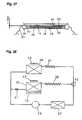
- FIG. 27is a schematic vertical sectional view showing a heater according to a twenty-fourth embodiment and a twenty-fifth embodiment of the present invention.
- FIG. 28is a schematic view showing a freezing refrigerator according to a twenty-sixth embodiment of the present invention.
- FIG. 29is a schematic vertical sectional view showing a refrigerator according to the twenty-sixth embodiment of the present invention.
- FIG. 30is a schematic vertical sectional view showing a portion of a defrosting device according to a twenty-seventh embodiment of the present invention.
- FIG. 31is a schematic vertical sectional view showing an upper portion of a freezing refrigerator according to a conventional freezing refrigerator.
- a heated temperature (simply referred to as “temperature”) of a defrosting device and a heater wire used in previous and subsequent descriptionsrefers respectively to a temperature of the defrosting device and a heated temperature when the heater wire is electrically operated or excited to radiate heat.
- reference numeral 18denotes a defrosting device for defrosting frost which adheres to an evaporator 10 .
- Reference numeral 19denotes a compressor.
- Reference numeral 20denotes a condenser.
- Reference numeral 21denotes a depression mechanism.
- flammable coolant(not shown) is sealed. This flammable coolant is formed of propane or isobutane as its main component.
- An ignition point or ignition temperature of the flammable coolantis generally considered to be 450 to 470° C.
- a freezing refrigerator with this structureis operated as described below.
- the evaporator 10 of the cooling cycleis cooled with operation of the compressor 19 with a result that inside air of the freezing refrigerator ventilates the cooled evaporator 10 with a fan 11 , which is simultaneously operated with operation of the compressor 19 . Then, cool air which is heat exchanged with the evaporator 10 is exhausted to an interior of the refrigerator. Then, the defrosting device is operated after lapse of an arbitrary operating time of the compressor 19 .
- this defrosting device 18With operation of this defrosting device 18 , the defrosting device 18 generates heat at a temperature lower than the ignition temperature of the flammable coolant used in the cooling cycle so that the defrosting device defrosts the evaporator 10 . Completion of defrosting is detected by a detection device (not shown), thereby temporarily suspending a non-cooled state of the inside of the refrigerator by frosting. If the flammable coolant inside of the cooling cycle leaks, the defrosting device 18 comes to have only a temperature lower than the ignition temperature of the flammable coolant used in the cooling cycle with a result that danger of ignition is lowered.
- reference numeral 22denotes a glass tube which is a constituent element of defrosting device 18 .
- Reference numeral 23denotes a heater wire which is a constituent element of the defrosting device 18 , and which is formed of a metal resistor located inside the glass tube 22 .
- Reference numeral 24denotes a straight portion of the heater wire 23 formed linearly at both end portions of the heater wire.
- Reference numeral 25denotes a spiral portion of the heater wire 23 excluding the straight portions 24 , with the spiral portion being formed in a spiral configuration so as to be accommodated to a length of the glass tube 22 within which the heater wire is defined.
- Reference numeral 26denotes a cap for preventing frost water from infiltrating into an interior of the glass tube 22 .
- a portion of the heater wire 23is affected by mutually adjacent portions of the heater wire 23 , and is ignited at a temperature at which a heated temperature of the spiral portion 25 , which rises in temperature, is lower than the ignition temperature of a flammable coolant to be used. Consequently, frost of evaporator 10 is melted to become water and is dripped from the evaporator 10 .
- a portion of the dripped wateris not directly dripped to the glass tube 22 , and dripped water falls to basin 13 from roof 16 and the caps 26 while remaining water is directly dripped to the basin 13 with a result that the water dripped to the basin 13 is exhausted from drain port 14 to an exterior thereof.
- the heater wire 23which is a heating body, is radiated to frost, which has adhered to the evaporator 10 and peripheral parts, through the glass tube 22 . Consequently, a surface temperature of the heater wire 23 which is electrically excited becomes lower than the ignition temperature of the flammable coolant. Furthermore, the heater wire 23 can prevent corrosion and deterioration owing to direct contact of defrosted water with the caps 26 . Thus, danger of ignition can be extremely lowered even when defrosting is conducted in a case where defrosting capability and life is secured to the same level as, or more than, a conventional level and the flammable coolant is leaked to an atmosphere of the defrosting device 18 .
- reference numeral 27denotes a lead wire connected to both ends of heater wire 23 .
- Symbol Ldenotes a length of spiral portion 25 .
- a surface temperature of the central portion, in a length direction, of the spiral portion 25 of the heater wire 23which rises in value, is lower than an ignition temperature of a flammable coolant to be used while securing defrosting capability and life to be the same as, or more than, conventional defrosting capability and life, danger of ignition is further lowered even when defrosting is conducted when flammable coolant is leaked to an atmosphere of the defrosting device 18 .
- symbol hdenotes a height of spiral portion 25 .
- gas in the vicinity of heater wire 23is warmed with heating of the heater wire to move in an upward direction with a result that gas in glass tube 22 is heated at an upper portion more than at a lower portion.
- the heater wire 23has a height h of the spiral portion 25 so that temperature at an upper portion of the spiral portion 25 rises.
- a surface temperature of the spiral portion 25 of the heater wire 23 which comes to have a higher temperatureis heated at a temperature lower than an ignition temperature of a flammable coolant to be used so that evaporator 10 is defrosted.
- symbol Ldenotes a length of a spiral portion 25 .
- the horizontal axisrepresents a heating value per unit area, which value is obtained by dividing a heating value of Joule heat of heater wire 23 present in length L of the spiral portion 25 by a surface area of the heater wire 23 present in length L of the spiral portion 25
- the vertical axisrepresents a surface temperature of the heater wire 23 .
- the heater wire 23is electrified with electricity through lead wires 27 at a defrosting time, so that the heater wire 23 is heated with Joule heat.
- defrosting device 18defrosts evaporator 10 at a heating value of lower than 2.5 W/cm 2 per unit area of the heater wire 23 at a portion present in length L of the spiral portion 25 .
- surface temperature of the heater wire 23rises with an increase in quantity of heat per unit area of the spiral portion 25 of the heater wire 23 .
- quantity of heat per unit areaexceeds 2.5 W/cm 2
- surface temperature of the heater wire 23becomes not lower than an ignition temperature of a flammable coolant to be used.
- temperature of the heater wire 23can be lower than the ignition temperature of the flammable coolant while securing defrosting capability and life to be the same as, or more than, conventional defrosting capability and life. Even when defrosting is conducted in a case where the flammable coolant is leaked to an atmosphere of defrosting device 18 , danger of ignition can be further lowered. Furthermore, when an entire heating value of the heater wire 23 is increased, surface temperature of the heater wire 23 rises.
- temperature of the heater wire 23can be lower than the ignition temperature of the flammable coolant irrespective of the entire heating value of the heater wire 23 by designing the fifth embodiment in such a manner that heating value per unit area becomes 2.5 W/cm 2 even when the entire heating value is increased, design of the defrosting device 18 for setting the flammable coolant to a temperature lower than the ignition temperature can be facilitated, so that the entire heating value of the heater wire 23 can be increased while being maintained lower than the ignition temperature of the flammable coolant.
- a heated temperature of the heater wire 23is lower than an ignition temperature of isobutane.
- a heated temperature of isobutaneis required to be about 360° C. or lower in consideration of a safety ratio with respect to the ignition temperature of isobutane which stands at about 460° C.
- a heating value per unit areais 0.67 W/cm 2 or lower.
- symbol Ddenotes an outer diameter of spiral portion 25 .
- the horizontal axis in FIG. 8represents a heating value per unit area obtained by dividing a heating value of Joule heat of heater wire 23 present within length L of the spiral portion 25 by a volume defined by length L and the outer diameter D of the spiral portion 25 , while the vertical axis represents a surface temperature of the heater wire 23 .
- defrosting device 18defrosts evaporator 10 at a heating value per unit area of lower than 8.5 W/cm 3 , which value is obtained by dividing the heating value of the Joule heat of the heater wire 23 present in length L of the spiral portion 25 by the volume defined by length L and outer diameter D of the spiral portion 25 .
- surface temperature of the heater wire 23rises along with a rise in a heating value per unit area of the spiral portion 25 .
- this heating value per unit areaexceeds 8.5 W/cm 3 , the surface temperature becomes not lower than an ignition temperature of a flammable coolant to be used.
- temperature of the heater wire 23can be lower than the ignition temperature of the flammable coolant while securing defrosting capability and life to be the same as, or more than, conventional defrosting capability and life. Even when defrosting is conducted in a case where the flammable coolant is leaked to an atmosphere of the defrosting device 18 , danger of ignition can be further lowered. Furthermore, in a case where the outer diameter D of the spiral portion 25 is changed, temperature of the heater wire 23 can be lower than the ignition temperature of the flammable coolant without affecting the outer diameter D of the spiral portion 25 of the heater wire 23 by designing the sixth embodiment in such a manner that a heating value is determined with respect to the volume calculated from the outer diameter D and length L of the spiral portion 25 .
- symbol Pdenotes a pitch of spiral portion 25 .
- the horizontal axis in FIG. 10represents a heating value Q which is obtained by subtracting a heating value per unit area, obtained by dividing a heating value of Joule heat present in length L of the spiral portion 25 by a surface area, from a coefficient obtained by dividing the pitch P by outer diameter D, while the vertical axis represents a surface temperature of heater wire 23 .
- defrosting device 18conducts defrosting of evaporator 10 at a heating value Q of lower than 9.2 W/cm 2 .
- surface temperature of the heater wire 23rises along with an increase in the heating value Q so that heat temperature becomes a temperature not lower than an ignition temperature of a flammable coolant to be used when the heating value Q exceeds 9.2 W/cm 2 .
- a temperature of the heater wire 23can be lower than the ignition temperature of the flammable coolant while securing defrosting capability and life to be not lower than conventional defrosting capability and life. Consequently, even when defrosting is conducted in a case of leakage of the flammable coolant to an atmosphere of the defrosting device 18 , danger of ignition can be lowered.
- a temperature of the flammable coolantcan be lower than the ignition temperature of the flammable coolant without affecting the change of the pitch and the outer diameter of the spiral portion by designing the spiral portion 25 so that the heating value Q becomes lower than 9.2 W/cm 2 . Consequently, design of the defrosting device 18 for setting a temperature to lower than the ignition temperature of the flammable coolant can be facilitated, and the pitch and the diameter of the spiral portion 25 , and an entire heating value of the heater wire 23 , can be freely changed while maintaining the temperature lower than the ignition temperature of the flammable coolant.
- a pitch of spiral portion 25is 2 mm.
- defrosting device 18is operated and electrification of the heater wire 23 is started, and the spiral portion 25 comes to have a higher temperature under influence of mutually adjacent portions of the heater wire 23 .
- a heated temperature at each part of the spiral portion 25is changed and scattered because of a change in an influence degree of the mutually adjacent portions of the heater wire resulting from unevenness in pitch at a time of processing.
- the pitch of the spiral portion 25is 2 mm, influence from the mutually adjacent portions of the heater wire can be decreased and unevenness can be suppressed.
- the heater wire 23 as a wholecomes to have a temperature lower than an ignition temperature of a flammable coolant to be used. Consequently, even when defrosting is conducted in a case of leakage of the flammable coolant to an atmosphere of the defrosting device 18 , danger of ignition can be lowered.
- the pitchis 2 mm in the eighth embodiment, but the same effect can be obtained when the pitch is more than 2 mm.
- reference numeral 28denotes a metal which is melted and disconnected at a predetermined temperature lower than an ignition temperature of a flammable coolant to be used.
- Reference numeral 29denotes a power source.
- the ninth embodimentat a defrosting time, electrification of heater wire 23 of defrosting device 18 is started from the power source 29 . Then, there is a possibility that a temperature of the heater wire 23 becomes not lower than the ignition temperature of the flammable coolant in a case where a high voltage is applied as a voltage change. At this time, when the heater wire 23 attains a predetermined temperature lower than the ignition temperature of the flammable coolant, heat is transmitted to the metal 28 and the metal 28 is melted and electrification of the heater wire 23 from the power source 29 is shielded with a result that heating of the heater wire 23 is lost and its temperature is lowered.
- reference numeral 30denotes a temperature fuse which is melted and disconnected at a predetermined temperature lower than an ignition temperature of a flammable coolant to be used.
- a surface temperature of heater wire 23becomes a temperature not lower than the ignition temperature of the flammable coolant in a case of application of a high voltage as a voltage change.
- the temperature fuse 30is used, the temperature fuse is melted when a temperature of defrosting device 18 attains a predetermined temperature lower than the ignition temperature of the flammable coolant with a result that input to the defrosting device 18 from power source 29 is shielded and a heated temperature of the defrosting device 18 ceases to rise.
- reference numeral 30denotes a temperature fuse formed of a metal which is melted and disconnected at a predetermined temperature lower than an ignition temperature of a flammable coolant to be used. With respect to a freezing refrigerator which is configured in this manner, operation will be explained hereinbelow.
- the temperature fuse 30is mounted in close contact with an outer periphery of a hull of the defrosting device 18 which comes into contact with gas in the refrigerator.
- a surface temperature of a heater wire(not shown) becomes not lower than the ignition temperature of the flammable coolant in a case where a high voltage is applied as a voltage change.
- the defrosting device 18can more accurately suppress a temperature rise before attaining the ignition temperature of the flammable coolant. Consequently, even when the defrosting device is conducted in a case of leakage of the flammable coolant to an atmosphere of the defrosting device 18 , danger of ignition can be further lowered, while maintenance of the temperature fuse 30 in a case of absence of a problem with the defrosting device 18 can be facilitated.
- temperature fuse 30is mounted on an upper portion of a hull of defrosting device 18 .
- an upper portion of the defrosting device 18comes to have a high temperature with respect to a lower portion thereof. Then, there is a possibility that a surface temperature of a heater wire (not shown) becomes not lower than an ignition temperature of a flammable coolant to be used in a case where a high voltage is applied as a voltage change.
- the temperature fuse 30is melted and disconnected, and input to the defrosting device 18 is shielded to suppress a rise in temperature.
- the temperature fuse 30is operated by detecting a temperature of the upper portion of the defrosting device 18 , which portion is a high temperature portion in a vertical direction of the defrosting device 18 . Consequently, a rise in temperature of the defrosting device in its entirety to a temperature not lower than the ignition temperature of the flammable coolant can be further suppressed with a result that danger of ignition can be lowered further even when defrosting is conducted in a case of leakage of the flammable coolant to an atmosphere of the defrosting device 18 . At the same time, maintenance of the temperature fuse 30 in a case of no problem with the defrosting device 18 is easy.
- temperature fuse 30is mounted on a lower portion of a hull of defrosting device 18 .
- frost melted from an evaporator (not shown) or the like located above the defrosting device 18forms defrost water, so that some water is indirectly dripped while remaining water is directly dripped to a basin (not shown).
- the defrost water which has dripped to the defrosting device 18comes into contact with an upper portion of the defrosting device 18 to be evaporated. However, little defrost water is dripped to the temperature fuse 30 located at a lower portion of the defrosting device 18 .
- a heated temperature of the defrosting device 18can be accurately detected, and a rise in temperature of the defrosting device to a temperature not lower than an ignition temperature of a flammable coolant to be used can be more accurately suppressed because of absence of a temperature drop owing to direct contact of the defrost water which is dripped from the evaporator located at an upper portion of the defrosting device 18 at a time of rise of surface temperature of the heater wire (not shown) to a temperature of not lower than the ignition temperature of the flammable coolant in a case of application of a high voltage as a voltage change.
- temperature fuse 30is mounted on a hull in the vicinity of a central portion (L/2) of defrosting device 18 . Since both ends of the defrosting device 18 come into contact with outside air, heat exchange is conducted with the outside air, and temperature is lowered so as to be less than that of the central portion. Consequently, the central portion of the defrosting device 18 becomes a high temperature portion. Then, there is a possibility that a surface temperature of a heater wire (not shown) becomes not lower than an ignition temperature of a flammable coolant to be used in a case where a high voltage is applied as a voltage change.
- the temperature fuse 30which is mounted on a portion in close contact therewith is melted and disconnected, and input to the defrosting device 18 is shielded to suppress a rise in temperature.
- the temperature fuse 30is operated by detecting a heated temperature of the central portion, which is a high temperature portion in a length direction of the defrosting device 18 , a rise in temperature to not lower than the ignition temperature of the flammable coolant of the defrosting device 18 in its entirety can be suppressed, and danger of ignition can be lowered even when defrosting is conducted in a case of leakage of the flammable coolant into an atmosphere of the defrosting device 18 , while maintenance of the temperature fuse 30 in a case of no problem with the defrosting device 18 is easy.
- temperature fuse 30is melted and disconnected at a temperature which is 100 to 200° C. lower than an ignition temperature of a flammable coolant to be used.
- a surface temperature of heater wire 23becomes not lower than the ignition temperature of the flammable coolant in a case where a high voltage is applied as a voltage change.
- the heater wire 23which is a heating body, comes to have a predetermined temperature in the vicinity of the ignition temperature of the flammable coolant, but lower than the ignition temperature thereof, a surface of glass tube 22 on an outer periphery of the heater wire 23 comes to have a temperature which is 100 to 200° C.
- the temperature fuse 30which is mounted on a surface of the glass tube 22 in close contact therewith, is melted and disconnected, and an input to the heater wire 23 is shielded to suppress a rise in temperature.
- a rise in temperature to not lower than an ignition temperature of an inflammable coolant to be usedcan be accurately suppressed. Even when defrosting is conducted in a case of leakage of the flammable coolant into an atmosphere of defrosting device 18 , danger of ignition can be lowered while maintenance of the temperature fuse 30 in a case of no problem with the defrosting device 18 is easy.
- temperature fuse 30is mounted on a surface of glass tube 22 on an outer periphery of straight portion 24 of heater wire 23 and is fixed to the glass tube 22 in close contact therewith with a cap 26 . Consequently, at a time of operation of defrosting device 18 , the heater wire 23 of the defrosting device rises with Joule heat so that heat is transmitted to the glass tube 22 on an outer periphery of the heater wire 23 while temperature of the glass tube 22 also rises in association with the heater wire 23 .
- the straight portion 24 of the heater wire 23comes to have a lower temperature because of smaller influence from adjacent mutual portions of the heater wire, like spiral portion 25 , so that the outer periphery of the straight portion 24 in the glass tube comes to have a lower temperature as well.
- the heater wireattains a certain temperature lower than an ignition temperature of a flammable coolant to be used
- the glass tube 22 on the outer periphery of the straight portion 24comes to have a predetermined temperature lower than a heated temperature of the heater wire 23 with a result that metal of the temperature fuse 30 is melted and disconnected, and electrification of the heater wire 23 is shielded, and the heated temperature of heater wire 23 is thus lowered.
- defrosting device 18can suppress a rise in temperature before attaining the ignition temperature of the flammable coolant so that danger of ignition can be lowered even when defrosting is conducted in a case of leakage of the flammable coolant to an atmosphere of the defrosting device 18 , while maintenance of the temperature fuse 30 in a case of no problem with the defrosting device 18 is easy. Furthermore, since the temperature fuse 30 detects a low temperature of a portion associated with the heated temperature of the heater wire 23 to operate the heater wire 23 , a cheaper fuse can be used as compared with a temperature fuse for a high temperature.
- the cap 26functions also as a holder of the temperature fuse 30 , the temperature fuse 30 is mounted on a portion of the cap 26 . It goes without saying that the same effect can be provided when the heater wire 23 is mounted on the surface of the glass tube 22 on the outer periphery of the straight portion 24 of the heater wire 23 .
- reference numeral 31denotes a temperature detection device.
- the temperature detection devicedetects a predetermined temperature
- electrification of heater wire 23 of defrosting device 18 from power source 29is shielded.
- the heater wire 23 of the defrosting device 18comes to have a higher temperature with Joule heat, so that heat is transmitted to glass tube 22 on an outer periphery of the heater wire 23 and temperature of the glass tube 22 also rises in association with the heater wire 23 .
- straight portion 24is affected little by mutually adjacent portions of the heater wire, i.e.
- a temperature of the straight portionis lowered so that a temperature of a portion on an outer periphery of the straight portion 24 is lowered in the glass tube 22 .
- temperature of the glass tube 22 on the outer periphery of the straight portion 24attains a predetermined temperature lower than a heated temperature of the heater wire 23 with a result that the temperature detection device 31 detects the predetermined temperature to shield electrification of the heater wire 23 , and the heated temperature of the heater wire 23 is lowered.
- the defrosting device 18can suppress a rise in temperature before attaining the ignition temperature of the flammable coolant. In a case where the flammable coolant is leaked to an atmosphere of the defrosting device 18 , danger of ignition can be lowered even when defrosting is conducted. Furthermore, since the temperature detection device 31 detects a low temperature at a portion which is associated with the heated temperature of the heater wire 23 , a cheaper temperature detection device can be used as compared with a higher temperature detection device.
- cap 26also serves as a holder of the temperature detection device 31 , the temperature detection device 31 is mounted in a portion of the cap. It goes without saying that the same effect can be obtained when the temperature detection device is mounted on a surface of the glass tube 22 on an outer periphery of the straight portion 24 of the heater wire 23 .
- reference numeral 31denotes a temperature detection device.
- the temperature detection device 31detects a temperature which is 310 to 410° C. lower than an ignition temperature of a flammable coolant to be used.
- the temperature detection device 31detects that temperature, electrification of heater wire 23 of defrosting device 18 from power source 29 is shielded.
- the heater wire 23comes to have a higher temperature by Joule heat, and heat is transmitted to glass tube 22 on an outer periphery of the heater wire 23 , so that a temperature of the glass tube 22 also rises in association with the heater wire 23 .
- temperature risecan be accurately suppressed before attaining the ignition temperature of the flammable coolant. Even when defrosting is conducted in a case of leakage of the flammable coolant to an atmosphere of the defrosting device 18 , danger of ignition can be suppressed while the temperature detection device 31 detects a low temperature at a portion associated with the heated temperature of the heater wire 23 . Consequently, a cheaper temperature detection device, as compared with a temperature device for a high temperature, can be used.
- reference numeral 32denotes a glass tube inner surface of glass tube 22 .
- Reference numeral 33denotes a glass tube outer surface of the glass tube 22 .
- Symbol Ldenotes a length of a spiral portion 25 .
- heater wire 23is electrified through a lead wire 27 , and the heater wire 23 is heated with Joule heat.
- defrosting device 18defrosts an evaporator (not shown) when a Joule heating value per unit area of the inner surface 32 of the glass tube at a portion present along the length L of the spiral portion 25 is lower than a predetermined temperature.
- surface temperature of the heater wire 23rises with an increase in a heating value per unit area, which corresponds to Joule heat, with respect to surface area of the glass tube inner surface 32 .
- temperaturebecomes not lower than an ignition temperature of a flammable coolant to be used.
- the glass tube 22is not designed in such a manner that an area of the inner surface 32 is not provided which is suitable to a heating value of the heater wire 23 , quantity of heat radiated to an exterior from the heater wire 23 through the glass tube 22 is decreased, and defrosting capability is lowered while a heated temperature of the heater wire 23 rises.
- a heating value per unit area, which corresponds to Joule heat, of the heater wire 23 with respect to the surface area of the glass tube inner surface 32is set to lower than a predetermined value so that a lowered portion of heat transmission quantity, resulting from a temperature drop, can be compensated with a heat transmission area. While maintaining all of heat radiated from the glass tube 22 on the same level as a conventional level, a temperature of the glass tube 22 associated with the heated temperature of the heater wire 23 can be lowered.
- a temperature of the heater wire 23can be lower than the ignition temperature of the flammable coolant. Even when defrosting is conducted in a case of leakage of the flammable coolant to an atmosphere of the defrosting device 18 , danger of ignition can be lowered. Furthermore, when an entire heating value is increased, surface temperature of the heater wire 23 increases.
- a temperature of the heater wire 23can be lower than the ignition temperature of the flammable coolant irrespective of the entire heating value of the heater wire 23 by designing the nineteenth embodiment in such a manner that a heating value per unit area of the heater wire 23 in its entirety becomes lower than a predetermined value.
- design of the defrosting device 18 for setting the flammable coolant to a temperature lower than the ignition temperature of the flammable coolantcan be easily made, and an entire heating value can be increased while maintaining a temperature lower than the ignition temperature of the flammable coolant.
- the horizontal axis of FIG. 22represents a heating value per unit area of a glass tube inner surface, which quantity is obtained by dividing a heating value of Joule heat of heater wire 23 present along length L of spiral portion 25 by surface area of glass tube inner surface 32 corresponding to length L of the spiral portion 25 , while the vertical axis of FIG. 22 represents a surface temperature of the heater wire 23 .
- coolant in a freezing cycleis isobutane.
- defrosting device 18defrosts an evaporator (not shown) when Joule heating value per surface area of the glass tube inner surface 32 of the portion present along length L of the spiral portion 25 is lower than 1.6 W/cm 2 .
- surface temperature of the heater wire 23rises with an increase in a heating value per unit area, which corresponds to Joule heat, with respect to surface area of the glass tube inner surface 32 .
- the heating value per unit areabecomes 1.6 W/cm 2
- the heating valuebecomes larger than an ignition temperature of the isobutane. That is, unless the glass tube is not designed so as to have an area of the glass tube inner surface 32 which is appropriate for a heating value of the heater wire 23 , quantity of heat radiated to an exterior from the heater wire 23 through the glass tube 22 is lowered, and defrosting capability is lowered while a heated temperature of the heater wire 23 rises.
- a lowered portion of a heat transmission quantity resulting from a temperature drop of the glass tubecan be compensated with a heat transmission area by setting to lower than 1.6 W/cm 2 a heating value per unit area, which corresponds to a Joule heat of the heater wire, with respect to surface area of the glass tube inner surface 32 .
- a heating value per unit areawhich corresponds to a Joule heat of the heater wire
- a temperature of the heater wire 23can be lower than the ignition temperature of the isobutane while securing defrosting capability and life to be the same as, or more than, conventional defrosting capability and life. Even when defrosting is conducted in a case of leakage of flammable coolant to an atmosphere of the defrosting device 18 , danger of ignition can be lowered. Furthermore, when an entire heating value of the heater wire 23 is increased, surface temperature of the heater wire 23 rises.
- a temperature of the heaterwire 23can be lower than the ignition temperature of the isobutane irrespective of the entire heating value of the heater wire 23 by designing this embodiment so that a heating value per unit area is lower than 1.6 W/cm 2 even when the entire heating value is increased. Consequently, design of the defrosting device 18 for setting a temperature to lower than the ignition temperature of the isobutane can easily be made, and the entire heating value can be increased while maintaining a temperature lower than the ignition temperature of the isobutane.
- the heated temperature of the heater wire 23is lower than the ignition temperature of the isobutane.
- the heated temperature of the heater wire 23it is required to set this temperature to 360° C. or lower in consideration of safety with respect to about 460° C., which is the ignition temperature of isobutane.
- a heating value per unit area of the glass tubeis 0.67 W/cm 2 or lower.
- reference numeral 34denotes air, which is gas inside of the glass tube 22 .
- Symbol ddenotes an outer diameter of spiral portion 25 of heater wire 23 .
- Symbol Ddenotes an inner diameter of the glass tube 22 .
- a distance between an outer peripheral portion of the spiral portion of the heater wire 23 and inner surface 32 of the glass tubeis 1 mm.
- heat radiated from a surface of heater wire 23 of defrosting device 18is radiated to an exterior from an outer surface of the spiral portion 25 of the heater wire 23 through a layer of air having a low transmission rate, which layer is present between the heater wire 23 and the glass tube 22 . Then, heat transmission of the glass tube inner surface 32 from the heater wire 23 , and heat radiation to the exterior, are promoted by reducing the layer of air having a low transmission rate to 1 mm with a result that heat radiation to the exterior is promoted and defrosting is promoted, while a temperature of a surface of the heater wire 23 is lowered.
- a temperature of the heater wire 23can be lower than an ignition temperature of a flammable coolant to be used while maintaining workability during the manufacture step at the same level as, or a higher level than, conventional workability.
- danger of ignitioncan be lowered.
- a distance between an outer peripheral portion of the spiral portion 25 of the heater wire 23 and the inner surface of the glass tube 22is 1 mm.
- the same, or a greater effectcan be obtained.
- the gas in the glass tubeis air.
- heat transmissionis unfavorable, the same effect can be obtained.
- a heated temperature of the heater wire 23is lower than the ignition temperature of the flammable coolant.
- isobutaneas the coolant
- a Joule heating value with respect to surface area of the heater wire 23is 0.67 W/cm 2 or lower
- a Joule heating quantity of the heater wire 23 with respect to the surface area of the inner surface of the glass tubeis 0.67 W/cm 2 or lower
- spiral portion 25 of heater wire 23 and glass tube inner surface 32come into contact with each other.
- heat radiated from the heater wire 23 of defrosting device 18is partially transmitted to the glass tube 22 through a contact surface with the glass tube inner surface 32 , to be radiated to an exterior from glass tube outer surface 33 , while remaining heat passes through an interior of the glass tube 22 from the glass tube inner surface 32 through air 34 inside of the glass tube 22 , to be radiated from the glass tube outer surface 33 .
- the glass tube 22has an extremely favorable heat transmission rate relative to that of air 34 in the glass tube 22 , heat transmission is promoted with contact of the heater wire 23 and the glass tube inner surface 32 , so that quantity of heat radiated from the heater wire 23 increases and defrosting is promoted while a heated temperature of the heater wire 23 is lowered.
- a temperature of a flammable coolant to be usedcan be set to lower than an ignition temperature of the flammable coolant, while securing defrosting capability and life to be the same as, or more than, conventional defrosting capability and life. Thus, even if defrosting is conducted, danger of ignition can be further lowered.
- defrosting device 18is provided with a roof 16 above glass tube 22 in which heater wire 23 is mounted.
- the roof 16has a square dent-like configuration, and fringes on both sides thereof are denoted by reference numeral 35 .
- the roof 16is mounted in such a manner that an open portion of the configuration thereof is located below.
- symbol Jdenotes a predetermined value of a size of a minimum distance portion between the roof 16 and glass tube outer surface 33 .
- An arrowdenotes a passage of convection air.
- the glass tube outer surface 33is heated with heating of the heater wire 23 so that heat is transmitted to peripheral air and a temperature rises and air moves in an upward direction by convection. Then, air fills the square dent-like configuration, and an overflow of the air moves above the roof 16 from the fringes 35 to defrost an evaporator (not shown) and other peripheral parts. Water which is liquefied through defrosting is dripped on an upper portion of the roof 16 and is dripped below the defrosting device without dripping on the glass tube via the fringes of the square dent-like configuration.
- a temperature of the heater wire 23can be lower than an ignition temperature of a flammable coolant to be used. Consequently, even when defrosting is conducted in a case of leakage of the flammable coolant to an atmosphere of the defrosting device 18 , danger of ignition can be lowered.
- thickness of glass tube 22is 1.0 mm.
- heat radiated from heater wire 23is radiated to an exterior from glass tube outer surface 33 , via thickness of the glass tube 22 , from glass tube inner surface 32 to defrost peripheral parts.
- thickness of the glass tube 22is 1.0 mm, quantity of heat radiated through the glass tube 22 from the heater wire 23 by promotion of heat transmission of the glass tube 22 increases while maintaining strength of the glass tube 22 . Consequently, defrosting is promoted while a heated temperature of the heater wire 23 is lowered.
- a temperature of the heater wire 23can be not lower than an ignition temperature of a flammable coolant to be used. Consequently, even when defrosting is conducted in a case of leakage of the flammable coolant to an atmosphere of defrosting device 18 , danger of ignition can be further lowered.
- the thickness of the glass tube 22is 1.0 mm, when the thickness is 1.5 mm or less, a defrosting degree is different, but the same effect can be obtained.
- quartzis used as a material for glass tube 22 .
- the following advantagecan be provided.
- a coolantis allowed to flow to an evaporator for cooling a freezing chamber and refrigerator chamber of a refrigerator housing. Then, the glass tube in the defrosting device located on a periphery of the evaporator comes to have a negative temperature. Then, at a defrosting time, a heater wire is heated with operation of the defrosting device so that the heater wire is heated and reaches a high temperature in a short time. A temperature of the glass tube changes from 300 to 450° C. in a short time. At this time, it sometimes happens that conventional glass is damaged because of a difference in linear swelling. There is a danger in that a flammable coolant being used catches fire when defrosting is conducted in a case where the flammable coolant is leaked to an atmosphere of the defrosting device in a damaged state.
- quartz glassis not damaged because linear swelling owing to temperature change is small. Consequently, when defrosting is conducted in a case of leakage of a flammable coolant to an atmosphere of a defrosting device, danger of ignition can be further lowered.
- reference numeral 36denotes a cooling device for a refrigerator chamber which has a high evaporation temperature.
- Reference numeral 37denotes a depression mechanism for a high evaporation temperature which has a small depression quantity for a high evaporation temperature.
- Reference numeral 38denotes a cooling device for a freezing chamber which has a low evaporation temperature.
- Reference numeral 39denotes a depression mechanism for low evaporation temperature having a large depression quantity for a low evaporation temperature.
- Reference numeral 40denotes a change-over valve for changing over a flow channel of a coolant.
- Reference numeral 41denotes a check valve for preventing a reverse current of the coolant to the cooling device 38 from the cooling device 36 .
- Reference numeral 42denotes a refrigerator fan for allowing air in refrigerator chamber 3 to pass through the cooling device 36 for heat exchange, thereby circulating cooling air.
- Reference numeral 43denotes a fan for freezing chamber 2 for circulating cooling air by allowing air in the freezing chamber 2 to pass through the cooling device 38 to circulate the cooling air through heat exchange.
- Reference numeral 44denotes a partition wall for the cooling device 36 , which serves as a duct for smoothly ventilating the cooling device 36 while preventing heat movement from the cooling device 36 to the refrigerator chamber 3 .
- Reference numeral 45denotes a discharge port for the refrigerator chamber 3 for discharging cool air which is heat exchanged with the cooling device 36 with operation of the fan 42 .
- Reference numeral 46denotes a partition wall of a cooling device for the freezing chamber 2 , which constitutes a duct for smoothly ventilating the cooling device 38 .
- Reference numeral 47denotes a discharge port of the freezing chamber 2 for discharging to the freezing chamber cool air which is heat exchanged with the cooling device 38 with operation of the fan 43 .
- Reference numeral 48denotes an evaporation detaining defrost water which is generated when the cooling device 38 is heat exchanged for automatic evaporation.
- a freezing cycle for cooling the refrigerator chamberhas a process such that when a temperature of the refrigerator chamber 3 is not lower than a certain temperature, a compressor 19 is operated, circulation of a flammable coolant (not shown in the cooling cycle) is started so that the flammable coolant is compressed with heat exchange with outside air, and the coolant is allowed to flow into the cooling device 36 via the depression mechanism 37 with operation of the change-over valve 40 , to be absorbed in the compressor 19 .
- a cooling cycle for cooling the freezing chamberhas a process such that when the freezing chamber 2 is at a temperature not lower than a set temperature, the compressor 19 is operated, circulation of the flammable coolant in the cooling cycle is started, and the flammable coolant is condensed with heat exchange with outside air at a condenser 20 with a result that the coolant is allowed to flow to the cooling device 38 via the depression mechanism 39 with operation of the change-over valve 40 , to be absorbed in the compressor 19 .
- air in the freezing chamber 2is absorbed from an inlet port 7 of the freezing chamber by operating the fan 43 together with operation of the compressor 19 .
- This airis allowed to pass through the cooling device 38 so that air cooled with heat exchange is discharged from the discharge port 47 to the freezing chamber 2 to cool the freezing chamber.
- the cooling device 38since air passing through the cooling device 38 is air only in the freezing chamber 2 , the cooling device 38 is small in size, and a heat exchange area is small, so that a frost area becomes small and frost quantity decreases.
- a defrosting device 18is operated to defrost the cooling device 38 and peripheral parts.
- coolant in piping of the cooling device 38is also heated.
- this heated coolantis evaporated in the piping of the cooling device 38 and moves to a low temperature portion, which is a portion that is not yet heated with the defrosting device 18 , to remove frost from a heated portion.
- the frostis melted, and the coolant is condensed by removing heat.
- part of the coolant which is condensedis partially detained in the cooling device 38 to be heated again with the defrosting device 18 .
- This operationis repeated so that the cooling device 38 in its entirety is defrosted, and defrost water obtained through defrosting is dripped on a basin 13 and is dripped from a drain outlet 14 to an evaporation plate 48 to be detained.
- the defrost water detained in the evaporation plate 48is heated at a time of operation of the compressor 19 to be naturally evaporated. In this manner, since the cooling device 38 cools only the freezing chamber 2 , a defrost quantity is small. Consequently, a heating value of the defrosting device 18 can be decreased, and a heated temperature of the defrosting device 18 is lowered with a decrease in a heating quantity.
- a conventional cooling devicesince a majority of coolant in a cooling cycle is present in an evaporator, which is a cooling device, a large heating value is required for heating by a defrosting device at a defrosting time, so that a large quantity of heat of the coolant is required except for a quantity of heat used for defrosting.
- a part of coolantis present in the cooling device 36 , a quantity of coolant in the cooling device 38 becomes very small as compared with a case of the conventional cooling device. Since a quantity of heat used in heating by the defrosting device, except for defrosting, at a defrosting time may be small, energy can be saved.
- a temperature of the defrosting devicecan be lower than an ignition temperature of a flammable coolant to be used, while maintaining defrosting capability and life to be the same as, or more than, conventional defrosting capability and life. Even in a case where defrosting is conducted in an environment of leakage of the flammable coolant to an atmosphere in which the defrosting device 18 is mounted, danger of ignition of the flammable coolant can be further lowered.
- reference numeral 49denotes an upper portion inclined plate which is inclined toward the right in a downward direction from above glass tube 22 and constitutes one roof.
- Reference numeral 50denotes a lower portion inclined plate which is inclined to the left in a downward direction from above the glass tube 22 and constitutes another roof. Plate 50 is located below the upper portion inclined plate 49 .
- Reference numeral 51denotes a slit between the upper portion inclined plate 49 and the lower portion inclined plate 50 .
- an arrowdenotes a passage of peripheral air of a defrosting device.
- heater wire 23 of the defrosting deviceis heated while the glass tube 22 , which is located on the heater wire 23 , and an outer periphery of the heater wire 23 comes to have a higher temperature. Then, air in the vicinity of the glass tube 22 is heated and rises to the upper portion inclined plate 49 and the lower portion inclined plate 50 as shown by an arrow. A portion of this air moves to an upper evaporator 10 through the slit 51 and defrosting is conducted through heat exchange with frost which adheres to the evaporator 10 and a periphery thereof. Then, defrost water is dripped to the upper portion inclined plate 49 and the lower portion inclined plate 50 , and falls through the upper portion inclined plate 49 and the lower portion inclined plate 50 without being directly dripped on the glass tube 22 .
- a quantity of heat radiated to an exteriorfurther increases, and a defrosting capability is further improved, while a quantity of heat used for a rise in a heated temperature of the heater wire 23 of the defrosting device decreases for an increased portion of a quantity of heat radiated to the exterior with a result that a surface temperature of the heater wire 23 is lowered and the surface temperature can be lower than an ignition temperature of a flammable coolant to be used.
Landscapes
- Engineering & Computer Science (AREA)
- Chemical & Material Sciences (AREA)
- Combustion & Propulsion (AREA)
- Physics & Mathematics (AREA)
- Mechanical Engineering (AREA)
- Thermal Sciences (AREA)
- General Engineering & Computer Science (AREA)
- Defrosting Systems (AREA)
- Resistance Heating (AREA)
Abstract
Description
Claims (41)
Applications Claiming Priority (3)
| Application Number | Priority Date | Filing Date | Title |
|---|---|---|---|
| JP11-135304 | 1999-05-17 | ||
| JP11135304AJP2000329447A (en) | 1999-05-17 | 1999-05-17 | Refrigerator and defrost heater |
| PCT/JP2000/003091WO2000070281A1 (en) | 1999-05-17 | 2000-05-15 | Refrigerator and defrosting heater |
Publications (1)
| Publication Number | Publication Date |
|---|---|
| US6684659B1true US6684659B1 (en) | 2004-02-03 |
Family
ID=15148594
Family Applications (1)
| Application Number | Title | Priority Date | Filing Date |
|---|---|---|---|
| US09/979,047Expired - LifetimeUS6684659B1 (en) | 1999-05-17 | 2000-05-15 | Refrigerator and defrosting heater |
Country Status (6)
| Country | Link |
|---|---|
| US (1) | US6684659B1 (en) |
| EP (1) | EP1180653A4 (en) |
| JP (1) | JP2000329447A (en) |
| KR (1) | KR100459276B1 (en) |
| CN (1) | CN1152228C (en) |
| WO (1) | WO2000070281A1 (en) |
Cited By (357)
| Publication number | Priority date | Publication date | Assignee | Title |
|---|---|---|---|---|
| US20110138834A1 (en)* | 2009-12-10 | 2011-06-16 | Panasonic Corporation | Refrigerating apparatus and storge device using the same |
| US20140352913A1 (en)* | 2013-05-31 | 2014-12-04 | Hamilton Sundstrand Corporation | Aircraft refrigeration unit evaporator heater |
| WO2017176351A1 (en)* | 2016-04-07 | 2017-10-12 | Hussmann Corporation | Refrigeration system with fluid defrost |
| US9909214B2 (en)* | 2015-10-15 | 2018-03-06 | Asm Ip Holding B.V. | Method for depositing dielectric film in trenches by PEALD |
| US10208999B2 (en)* | 2017-03-02 | 2019-02-19 | Haier Us Appliance Solutions, Inc. | Refrigeration heating assembly and method of operation |
| US10229833B2 (en) | 2016-11-01 | 2019-03-12 | Asm Ip Holding B.V. | Methods for forming a transition metal nitride film on a substrate by atomic layer deposition and related semiconductor device structures |
| US10249577B2 (en) | 2016-05-17 | 2019-04-02 | Asm Ip Holding B.V. | Method of forming metal interconnection and method of fabricating semiconductor apparatus using the method |
| US10249524B2 (en) | 2017-08-09 | 2019-04-02 | Asm Ip Holding B.V. | Cassette holder assembly for a substrate cassette and holding member for use in such assembly |
| US10262859B2 (en) | 2016-03-24 | 2019-04-16 | Asm Ip Holding B.V. | Process for forming a film on a substrate using multi-port injection assemblies |
| US10269558B2 (en) | 2016-12-22 | 2019-04-23 | Asm Ip Holding B.V. | Method of forming a structure on a substrate |
| US10276355B2 (en) | 2015-03-12 | 2019-04-30 | Asm Ip Holding B.V. | Multi-zone reactor, system including the reactor, and method of using the same |
| US10283353B2 (en) | 2017-03-29 | 2019-05-07 | Asm Ip Holding B.V. | Method of reforming insulating film deposited on substrate with recess pattern |
| US10290508B1 (en) | 2017-12-05 | 2019-05-14 | Asm Ip Holding B.V. | Method for forming vertical spacers for spacer-defined patterning |
| US10312055B2 (en) | 2017-07-26 | 2019-06-04 | Asm Ip Holding B.V. | Method of depositing film by PEALD using negative bias |
| US10312129B2 (en) | 2015-09-29 | 2019-06-04 | Asm Ip Holding B.V. | Variable adjustment for precise matching of multiple chamber cavity housings |
| US10319588B2 (en) | 2017-10-10 | 2019-06-11 | Asm Ip Holding B.V. | Method for depositing a metal chalcogenide on a substrate by cyclical deposition |
| US10322384B2 (en) | 2015-11-09 | 2019-06-18 | Asm Ip Holding B.V. | Counter flow mixer for process chamber |
| US10340125B2 (en) | 2013-03-08 | 2019-07-02 | Asm Ip Holding B.V. | Pulsed remote plasma method and system |
| US10340135B2 (en) | 2016-11-28 | 2019-07-02 | Asm Ip Holding B.V. | Method of topologically restricted plasma-enhanced cyclic deposition of silicon or metal nitride |
| US10343920B2 (en) | 2016-03-18 | 2019-07-09 | Asm Ip Holding B.V. | Aligned carbon nanotubes |
| US10361201B2 (en) | 2013-09-27 | 2019-07-23 | Asm Ip Holding B.V. | Semiconductor structure and device formed using selective epitaxial process |
| US10364493B2 (en) | 2016-08-25 | 2019-07-30 | Asm Ip Holding B.V. | Exhaust apparatus and substrate processing apparatus having an exhaust line with a first ring having at least one hole on a lateral side thereof placed in the exhaust line |
| US10366864B2 (en) | 2013-03-08 | 2019-07-30 | Asm Ip Holding B.V. | Method and system for in-situ formation of intermediate reactive species |
| US10364496B2 (en) | 2011-06-27 | 2019-07-30 | Asm Ip Holding B.V. | Dual section module having shared and unshared mass flow controllers |
| US10367080B2 (en) | 2016-05-02 | 2019-07-30 | Asm Ip Holding B.V. | Method of forming a germanium oxynitride film |
| US10381219B1 (en) | 2018-10-25 | 2019-08-13 | Asm Ip Holding B.V. | Methods for forming a silicon nitride film |
| US10378106B2 (en) | 2008-11-14 | 2019-08-13 | Asm Ip Holding B.V. | Method of forming insulation film by modified PEALD |
| US10381226B2 (en) | 2016-07-27 | 2019-08-13 | Asm Ip Holding B.V. | Method of processing substrate |
| US10388509B2 (en) | 2016-06-28 | 2019-08-20 | Asm Ip Holding B.V. | Formation of epitaxial layers via dislocation filtering |
| US10388513B1 (en) | 2018-07-03 | 2019-08-20 | Asm Ip Holding B.V. | Method for depositing silicon-free carbon-containing film as gap-fill layer by pulse plasma-assisted deposition |
| US10395919B2 (en) | 2016-07-28 | 2019-08-27 | Asm Ip Holding B.V. | Method and apparatus for filling a gap |
| US10403504B2 (en) | 2017-10-05 | 2019-09-03 | Asm Ip Holding B.V. | Method for selectively depositing a metallic film on a substrate |
| US10410943B2 (en) | 2016-10-13 | 2019-09-10 | Asm Ip Holding B.V. | Method for passivating a surface of a semiconductor and related systems |
| US10438965B2 (en) | 2014-12-22 | 2019-10-08 | Asm Ip Holding B.V. | Semiconductor device and manufacturing method thereof |
| US10435790B2 (en) | 2016-11-01 | 2019-10-08 | Asm Ip Holding B.V. | Method of subatmospheric plasma-enhanced ALD using capacitively coupled electrodes with narrow gap |
| US10446393B2 (en) | 2017-05-08 | 2019-10-15 | Asm Ip Holding B.V. | Methods for forming silicon-containing epitaxial layers and related semiconductor device structures |
| US10458018B2 (en) | 2015-06-26 | 2019-10-29 | Asm Ip Holding B.V. | Structures including metal carbide material, devices including the structures, and methods of forming same |
| US10468261B2 (en) | 2017-02-15 | 2019-11-05 | Asm Ip Holding B.V. | Methods for forming a metallic film on a substrate by cyclical deposition and related semiconductor device structures |
| US10468251B2 (en) | 2016-02-19 | 2019-11-05 | Asm Ip Holding B.V. | Method for forming spacers using silicon nitride film for spacer-defined multiple patterning |
| US10480072B2 (en) | 2009-04-06 | 2019-11-19 | Asm Ip Holding B.V. | Semiconductor processing reactor and components thereof |
| US10483099B1 (en) | 2018-07-26 | 2019-11-19 | Asm Ip Holding B.V. | Method for forming thermally stable organosilicon polymer film |
| US10501866B2 (en) | 2016-03-09 | 2019-12-10 | Asm Ip Holding B.V. | Gas distribution apparatus for improved film uniformity in an epitaxial system |
| US10504742B2 (en) | 2017-05-31 | 2019-12-10 | Asm Ip Holding B.V. | Method of atomic layer etching using hydrogen plasma |
| US10510536B2 (en) | 2018-03-29 | 2019-12-17 | Asm Ip Holding B.V. | Method of depositing a co-doped polysilicon film on a surface of a substrate within a reaction chamber |
| US10529563B2 (en) | 2017-03-29 | 2020-01-07 | Asm Ip Holdings B.V. | Method for forming doped metal oxide films on a substrate by cyclical deposition and related semiconductor device structures |
| US10529542B2 (en) | 2015-03-11 | 2020-01-07 | Asm Ip Holdings B.V. | Cross-flow reactor and method |
| US10529554B2 (en) | 2016-02-19 | 2020-01-07 | Asm Ip Holding B.V. | Method for forming silicon nitride film selectively on sidewalls or flat surfaces of trenches |
| US10535516B2 (en) | 2018-02-01 | 2020-01-14 | Asm Ip Holdings B.V. | Method for depositing a semiconductor structure on a surface of a substrate and related semiconductor structures |
| US10541173B2 (en) | 2016-07-08 | 2020-01-21 | Asm Ip Holding B.V. | Selective deposition method to form air gaps |
| US10541333B2 (en) | 2017-07-19 | 2020-01-21 | Asm Ip Holding B.V. | Method for depositing a group IV semiconductor and related semiconductor device structures |
| US10559458B1 (en) | 2018-11-26 | 2020-02-11 | Asm Ip Holding B.V. | Method of forming oxynitride film |
| US10566223B2 (en) | 2012-08-28 | 2020-02-18 | Asm Ip Holdings B.V. | Systems and methods for dynamic semiconductor process scheduling |
| US10561975B2 (en) | 2014-10-07 | 2020-02-18 | Asm Ip Holdings B.V. | Variable conductance gas distribution apparatus and method |
| US10590535B2 (en) | 2017-07-26 | 2020-03-17 | Asm Ip Holdings B.V. | Chemical treatment, deposition and/or infiltration apparatus and method for using the same |
| US10600673B2 (en) | 2015-07-07 | 2020-03-24 | Asm Ip Holding B.V. | Magnetic susceptor to baseplate seal |
| US10605530B2 (en) | 2017-07-26 | 2020-03-31 | Asm Ip Holding B.V. | Assembly of a liner and a flange for a vertical furnace as well as the liner and the vertical furnace |
| US10604847B2 (en) | 2014-03-18 | 2020-03-31 | Asm Ip Holding B.V. | Gas distribution system, reactor including the system, and methods of using the same |
| US10607895B2 (en) | 2017-09-18 | 2020-03-31 | Asm Ip Holdings B.V. | Method for forming a semiconductor device structure comprising a gate fill metal |
| US10612136B2 (en) | 2018-06-29 | 2020-04-07 | ASM IP Holding, B.V. | Temperature-controlled flange and reactor system including same |
| US10612137B2 (en) | 2016-07-08 | 2020-04-07 | Asm Ip Holdings B.V. | Organic reactants for atomic layer deposition |
| USD880437S1 (en) | 2018-02-01 | 2020-04-07 | Asm Ip Holding B.V. | Gas supply plate for semiconductor manufacturing apparatus |
| US10622375B2 (en) | 2016-11-07 | 2020-04-14 | Asm Ip Holding B.V. | Method of processing a substrate and a device manufactured by using the method |
| US10643904B2 (en) | 2016-11-01 | 2020-05-05 | Asm Ip Holdings B.V. | Methods for forming a semiconductor device and related semiconductor device structures |
| US10643826B2 (en) | 2016-10-26 | 2020-05-05 | Asm Ip Holdings B.V. | Methods for thermally calibrating reaction chambers |
| US10658181B2 (en) | 2018-02-20 | 2020-05-19 | Asm Ip Holding B.V. | Method of spacer-defined direct patterning in semiconductor fabrication |
| US10655221B2 (en) | 2017-02-09 | 2020-05-19 | Asm Ip Holding B.V. | Method for depositing oxide film by thermal ALD and PEALD |
| US10658205B2 (en) | 2017-09-28 | 2020-05-19 | Asm Ip Holdings B.V. | Chemical dispensing apparatus and methods for dispensing a chemical to a reaction chamber |
| US10665452B2 (en) | 2016-05-02 | 2020-05-26 | Asm Ip Holdings B.V. | Source/drain performance through conformal solid state doping |
| US10683571B2 (en) | 2014-02-25 | 2020-06-16 | Asm Ip Holding B.V. | Gas supply manifold and method of supplying gases to chamber using same |
| US10685834B2 (en) | 2017-07-05 | 2020-06-16 | Asm Ip Holdings B.V. | Methods for forming a silicon germanium tin layer and related semiconductor device structures |
| US10692741B2 (en) | 2017-08-08 | 2020-06-23 | Asm Ip Holdings B.V. | Radiation shield |
| US10707106B2 (en) | 2011-06-06 | 2020-07-07 | Asm Ip Holding B.V. | High-throughput semiconductor-processing apparatus equipped with multiple dual-chamber modules |
| US10714385B2 (en) | 2016-07-19 | 2020-07-14 | Asm Ip Holding B.V. | Selective deposition of tungsten |
| US10714315B2 (en) | 2012-10-12 | 2020-07-14 | Asm Ip Holdings B.V. | Semiconductor reaction chamber showerhead |
| US10714335B2 (en) | 2017-04-25 | 2020-07-14 | Asm Ip Holding B.V. | Method of depositing thin film and method of manufacturing semiconductor device |
| US10714350B2 (en) | 2016-11-01 | 2020-07-14 | ASM IP Holdings, B.V. | Methods for forming a transition metal niobium nitride film on a substrate by atomic layer deposition and related semiconductor device structures |
| US10731249B2 (en) | 2018-02-15 | 2020-08-04 | Asm Ip Holding B.V. | Method of forming a transition metal containing film on a substrate by a cyclical deposition process, a method for supplying a transition metal halide compound to a reaction chamber, and related vapor deposition apparatus |
| US10734497B2 (en) | 2017-07-18 | 2020-08-04 | Asm Ip Holding B.V. | Methods for forming a semiconductor device structure and related semiconductor device structures |
| US10734244B2 (en) | 2017-11-16 | 2020-08-04 | Asm Ip Holding B.V. | Method of processing a substrate and a device manufactured by the same |
| US10741385B2 (en) | 2016-07-28 | 2020-08-11 | Asm Ip Holding B.V. | Method and apparatus for filling a gap |
| US10755922B2 (en) | 2018-07-03 | 2020-08-25 | Asm Ip Holding B.V. | Method for depositing silicon-free carbon-containing film as gap-fill layer by pulse plasma-assisted deposition |
| US10770336B2 (en) | 2017-08-08 | 2020-09-08 | Asm Ip Holding B.V. | Substrate lift mechanism and reactor including same |
| US10767789B2 (en) | 2018-07-16 | 2020-09-08 | Asm Ip Holding B.V. | Diaphragm valves, valve components, and methods for forming valve components |
| US10770286B2 (en) | 2017-05-08 | 2020-09-08 | Asm Ip Holdings B.V. | Methods for selectively forming a silicon nitride film on a substrate and related semiconductor device structures |
| US10787741B2 (en) | 2014-08-21 | 2020-09-29 | Asm Ip Holding B.V. | Method and system for in situ formation of gas-phase compounds |
| US10797133B2 (en) | 2018-06-21 | 2020-10-06 | Asm Ip Holding B.V. | Method for depositing a phosphorus doped silicon arsenide film and related semiconductor device structures |
| US10804098B2 (en) | 2009-08-14 | 2020-10-13 | Asm Ip Holding B.V. | Systems and methods for thin-film deposition of metal oxides using excited nitrogen-oxygen species |
| US10811256B2 (en) | 2018-10-16 | 2020-10-20 | Asm Ip Holding B.V. | Method for etching a carbon-containing feature |
| US10818758B2 (en) | 2018-11-16 | 2020-10-27 | Asm Ip Holding B.V. | Methods for forming a metal silicate film on a substrate in a reaction chamber and related semiconductor device structures |
| USD900036S1 (en) | 2017-08-24 | 2020-10-27 | Asm Ip Holding B.V. | Heater electrical connector and adapter |
| US10832903B2 (en) | 2011-10-28 | 2020-11-10 | Asm Ip Holding B.V. | Process feed management for semiconductor substrate processing |
| US10829852B2 (en) | 2018-08-16 | 2020-11-10 | Asm Ip Holding B.V. | Gas distribution device for a wafer processing apparatus |
| US10847365B2 (en) | 2018-10-11 | 2020-11-24 | Asm Ip Holding B.V. | Method of forming conformal silicon carbide film by cyclic CVD |
| US10847366B2 (en) | 2018-11-16 | 2020-11-24 | Asm Ip Holding B.V. | Methods for depositing a transition metal chalcogenide film on a substrate by a cyclical deposition process |
| US10847371B2 (en) | 2018-03-27 | 2020-11-24 | Asm Ip Holding B.V. | Method of forming an electrode on a substrate and a semiconductor device structure including an electrode |
| US10844484B2 (en) | 2017-09-22 | 2020-11-24 | Asm Ip Holding B.V. | Apparatus for dispensing a vapor phase reactant to a reaction chamber and related methods |
| US10851456B2 (en) | 2016-04-21 | 2020-12-01 | Asm Ip Holding B.V. | Deposition of metal borides |
| US10854498B2 (en) | 2011-07-15 | 2020-12-01 | Asm Ip Holding B.V. | Wafer-supporting device and method for producing same |
| USD903477S1 (en) | 2018-01-24 | 2020-12-01 | Asm Ip Holdings B.V. | Metal clamp |
| US10858737B2 (en) | 2014-07-28 | 2020-12-08 | Asm Ip Holding B.V. | Showerhead assembly and components thereof |
| US10865475B2 (en) | 2016-04-21 | 2020-12-15 | Asm Ip Holding B.V. | Deposition of metal borides and silicides |
| US10867786B2 (en) | 2018-03-30 | 2020-12-15 | Asm Ip Holding B.V. | Substrate processing method |
| US10867788B2 (en) | 2016-12-28 | 2020-12-15 | Asm Ip Holding B.V. | Method of forming a structure on a substrate |
| US10872771B2 (en) | 2018-01-16 | 2020-12-22 | Asm Ip Holding B. V. | Method for depositing a material film on a substrate within a reaction chamber by a cyclical deposition process and related device structures |
| US10886123B2 (en) | 2017-06-02 | 2021-01-05 | Asm Ip Holding B.V. | Methods for forming low temperature semiconductor layers and related semiconductor device structures |
| US10883175B2 (en) | 2018-08-09 | 2021-01-05 | Asm Ip Holding B.V. | Vertical furnace for processing substrates and a liner for use therein |
| US10892156B2 (en) | 2017-05-08 | 2021-01-12 | Asm Ip Holding B.V. | Methods for forming a silicon nitride film on a substrate and related semiconductor device structures |
| US10896820B2 (en) | 2018-02-14 | 2021-01-19 | Asm Ip Holding B.V. | Method for depositing a ruthenium-containing film on a substrate by a cyclical deposition process |
| US10910262B2 (en) | 2017-11-16 | 2021-02-02 | Asm Ip Holding B.V. | Method of selectively depositing a capping layer structure on a semiconductor device structure |
| US10914004B2 (en) | 2018-06-29 | 2021-02-09 | Asm Ip Holding B.V. | Thin-film deposition method and manufacturing method of semiconductor device |
| US10923344B2 (en) | 2017-10-30 | 2021-02-16 | Asm Ip Holding B.V. | Methods for forming a semiconductor structure and related semiconductor structures |
| US10928731B2 (en) | 2017-09-21 | 2021-02-23 | Asm Ip Holding B.V. | Method of sequential infiltration synthesis treatment of infiltrateable material and structures and devices formed using same |
| US10934619B2 (en) | 2016-11-15 | 2021-03-02 | Asm Ip Holding B.V. | Gas supply unit and substrate processing apparatus including the gas supply unit |
| US10941490B2 (en) | 2014-10-07 | 2021-03-09 | Asm Ip Holding B.V. | Multiple temperature range susceptor, assembly, reactor and system including the susceptor, and methods of using the same |
| US10975470B2 (en) | 2018-02-23 | 2021-04-13 | Asm Ip Holding B.V. | Apparatus for detecting or monitoring for a chemical precursor in a high temperature environment |
| US11001925B2 (en) | 2016-12-19 | 2021-05-11 | Asm Ip Holding B.V. | Substrate processing apparatus |
| US11018002B2 (en) | 2017-07-19 | 2021-05-25 | Asm Ip Holding B.V. | Method for selectively depositing a Group IV semiconductor and related semiconductor device structures |
| US11015245B2 (en) | 2014-03-19 | 2021-05-25 | Asm Ip Holding B.V. | Gas-phase reactor and system having exhaust plenum and components thereof |
| US11018047B2 (en) | 2018-01-25 | 2021-05-25 | Asm Ip Holding B.V. | Hybrid lift pin |
| US11024523B2 (en) | 2018-09-11 | 2021-06-01 | Asm Ip Holding B.V. | Substrate processing apparatus and method |
| US11022879B2 (en) | 2017-11-24 | 2021-06-01 | Asm Ip Holding B.V. | Method of forming an enhanced unexposed photoresist layer |
| US11031242B2 (en) | 2018-11-07 | 2021-06-08 | Asm Ip Holding B.V. | Methods for depositing a boron doped silicon germanium film |
| USD922229S1 (en) | 2019-06-05 | 2021-06-15 | Asm Ip Holding B.V. | Device for controlling a temperature of a gas supply unit |
| US11049751B2 (en) | 2018-09-14 | 2021-06-29 | Asm Ip Holding B.V. | Cassette supply system to store and handle cassettes and processing apparatus equipped therewith |
| US11056344B2 (en) | 2017-08-30 | 2021-07-06 | Asm Ip Holding B.V. | Layer forming method |
| US11053591B2 (en) | 2018-08-06 | 2021-07-06 | Asm Ip Holding B.V. | Multi-port gas injection system and reactor system including same |
| US11056567B2 (en) | 2018-05-11 | 2021-07-06 | Asm Ip Holding B.V. | Method of forming a doped metal carbide film on a substrate and related semiconductor device structures |
| US11069510B2 (en) | 2017-08-30 | 2021-07-20 | Asm Ip Holding B.V. | Substrate processing apparatus |
| US11081345B2 (en) | 2018-02-06 | 2021-08-03 | Asm Ip Holding B.V. | Method of post-deposition treatment for silicon oxide film |
| US11088002B2 (en) | 2018-03-29 | 2021-08-10 | Asm Ip Holding B.V. | Substrate rack and a substrate processing system and method |
| US11087997B2 (en) | 2018-10-31 | 2021-08-10 | Asm Ip Holding B.V. | Substrate processing apparatus for processing substrates |
| US11114294B2 (en) | 2019-03-08 | 2021-09-07 | Asm Ip Holding B.V. | Structure including SiOC layer and method of forming same |
| US11114283B2 (en) | 2018-03-16 | 2021-09-07 | Asm Ip Holding B.V. | Reactor, system including the reactor, and methods of manufacturing and using same |
| USD930782S1 (en) | 2019-08-22 | 2021-09-14 | Asm Ip Holding B.V. | Gas distributor |
| US11127617B2 (en) | 2017-11-27 | 2021-09-21 | Asm Ip Holding B.V. | Storage device for storing wafer cassettes for use with a batch furnace |
| US11127589B2 (en) | 2019-02-01 | 2021-09-21 | Asm Ip Holding B.V. | Method of topology-selective film formation of silicon oxide |
| USD931978S1 (en) | 2019-06-27 | 2021-09-28 | Asm Ip Holding B.V. | Showerhead vacuum transport |
| US11139191B2 (en) | 2017-08-09 | 2021-10-05 | Asm Ip Holding B.V. | Storage apparatus for storing cassettes for substrates and processing apparatus equipped therewith |
| US11139308B2 (en) | 2015-12-29 | 2021-10-05 | Asm Ip Holding B.V. | Atomic layer deposition of III-V compounds to form V-NAND devices |
| US11158513B2 (en) | 2018-12-13 | 2021-10-26 | Asm Ip Holding B.V. | Methods for forming a rhenium-containing film on a substrate by a cyclical deposition process and related semiconductor device structures |
| US11171025B2 (en) | 2019-01-22 | 2021-11-09 | Asm Ip Holding B.V. | Substrate processing device |
| USD935572S1 (en) | 2019-05-24 | 2021-11-09 | Asm Ip Holding B.V. | Gas channel plate |
| US11205585B2 (en) | 2016-07-28 | 2021-12-21 | Asm Ip Holding B.V. | Substrate processing apparatus and method of operating the same |
| US11217444B2 (en) | 2018-11-30 | 2022-01-04 | Asm Ip Holding B.V. | Method for forming an ultraviolet radiation responsive metal oxide-containing film |
| US11222772B2 (en) | 2016-12-14 | 2022-01-11 | Asm Ip Holding B.V. | Substrate processing apparatus |
| USD940837S1 (en) | 2019-08-22 | 2022-01-11 | Asm Ip Holding B.V. | Electrode |
| US11227782B2 (en) | 2019-07-31 | 2022-01-18 | Asm Ip Holding B.V. | Vertical batch furnace assembly |
| US11227789B2 (en) | 2019-02-20 | 2022-01-18 | Asm Ip Holding B.V. | Method and apparatus for filling a recess formed within a substrate surface |
| US11233133B2 (en) | 2015-10-21 | 2022-01-25 | Asm Ip Holding B.V. | NbMC layers |
| US11230766B2 (en) | 2018-03-29 | 2022-01-25 | Asm Ip Holding B.V. | Substrate processing apparatus and method |
| US11232963B2 (en) | 2018-10-03 | 2022-01-25 | Asm Ip Holding B.V. | Substrate processing apparatus and method |
| US11251040B2 (en) | 2019-02-20 | 2022-02-15 | Asm Ip Holding B.V. | Cyclical deposition method including treatment step and apparatus for same |
| US11251068B2 (en) | 2018-10-19 | 2022-02-15 | Asm Ip Holding B.V. | Substrate processing apparatus and substrate processing method |
| USD944946S1 (en) | 2019-06-14 | 2022-03-01 | Asm Ip Holding B.V. | Shower plate |
| US11270899B2 (en) | 2018-06-04 | 2022-03-08 | Asm Ip Holding B.V. | Wafer handling chamber with moisture reduction |
| US11274369B2 (en) | 2018-09-11 | 2022-03-15 | Asm Ip Holding B.V. | Thin film deposition method |
| US11282698B2 (en) | 2019-07-19 | 2022-03-22 | Asm Ip Holding B.V. | Method of forming topology-controlled amorphous carbon polymer film |
| US11289326B2 (en) | 2019-05-07 | 2022-03-29 | Asm Ip Holding B.V. | Method for reforming amorphous carbon polymer film |
| US11286562B2 (en) | 2018-06-08 | 2022-03-29 | Asm Ip Holding B.V. | Gas-phase chemical reactor and method of using same |
| US11286558B2 (en) | 2019-08-23 | 2022-03-29 | Asm Ip Holding B.V. | Methods for depositing a molybdenum nitride film on a surface of a substrate by a cyclical deposition process and related semiconductor device structures including a molybdenum nitride film |
| USD947913S1 (en) | 2019-05-17 | 2022-04-05 | Asm Ip Holding B.V. | Susceptor shaft |
| US11295980B2 (en) | 2017-08-30 | 2022-04-05 | Asm Ip Holding B.V. | Methods for depositing a molybdenum metal film over a dielectric surface of a substrate by a cyclical deposition process and related semiconductor device structures |
| USD948463S1 (en) | 2018-10-24 | 2022-04-12 | Asm Ip Holding B.V. | Susceptor for semiconductor substrate supporting apparatus |
| US11306395B2 (en) | 2017-06-28 | 2022-04-19 | Asm Ip Holding B.V. | Methods for depositing a transition metal nitride film on a substrate by atomic layer deposition and related deposition apparatus |
| USD949319S1 (en) | 2019-08-22 | 2022-04-19 | Asm Ip Holding B.V. | Exhaust duct |
| US11315794B2 (en) | 2019-10-21 | 2022-04-26 | Asm Ip Holding B.V. | Apparatus and methods for selectively etching films |
| US11339476B2 (en) | 2019-10-08 | 2022-05-24 | Asm Ip Holding B.V. | Substrate processing device having connection plates, substrate processing method |
| US11342216B2 (en) | 2019-02-20 | 2022-05-24 | Asm Ip Holding B.V. | Cyclical deposition method and apparatus for filling a recess formed within a substrate surface |
| US11345999B2 (en) | 2019-06-06 | 2022-05-31 | Asm Ip Holding B.V. | Method of using a gas-phase reactor system including analyzing exhausted gas |
| US11355338B2 (en) | 2019-05-10 | 2022-06-07 | Asm Ip Holding B.V. | Method of depositing material onto a surface and structure formed according to the method |
| US11361990B2 (en) | 2018-05-28 | 2022-06-14 | Asm Ip Holding B.V. | Substrate processing method and device manufactured by using the same |
| US11374112B2 (en) | 2017-07-19 | 2022-06-28 | Asm Ip Holding B.V. | Method for depositing a group IV semiconductor and related semiconductor device structures |
| US11378337B2 (en) | 2019-03-28 | 2022-07-05 | Asm Ip Holding B.V. | Door opener and substrate processing apparatus provided therewith |
| US11393690B2 (en) | 2018-01-19 | 2022-07-19 | Asm Ip Holding B.V. | Deposition method |
| US11390946B2 (en) | 2019-01-17 | 2022-07-19 | Asm Ip Holding B.V. | Methods of forming a transition metal containing film on a substrate by a cyclical deposition process |
| US11390950B2 (en) | 2017-01-10 | 2022-07-19 | Asm Ip Holding B.V. | Reactor system and method to reduce residue buildup during a film deposition process |
| US11390945B2 (en) | 2019-07-03 | 2022-07-19 | Asm Ip Holding B.V. | Temperature control assembly for substrate processing apparatus and method of using same |
| US11401605B2 (en) | 2019-11-26 | 2022-08-02 | Asm Ip Holding B.V. | Substrate processing apparatus |
| US11414760B2 (en) | 2018-10-08 | 2022-08-16 | Asm Ip Holding B.V. | Substrate support unit, thin film deposition apparatus including the same, and substrate processing apparatus including the same |
| US11424119B2 (en) | 2019-03-08 | 2022-08-23 | Asm Ip Holding B.V. | Method for selective deposition of silicon nitride layer and structure including selectively-deposited silicon nitride layer |
| US11430640B2 (en) | 2019-07-30 | 2022-08-30 | Asm Ip Holding B.V. | Substrate processing apparatus |
| US11428455B2 (en)* | 2017-05-25 | 2022-08-30 | Lg Electronics Inc. | Defrosting apparatus and refrigerator comprising same |
| US11430674B2 (en) | 2018-08-22 | 2022-08-30 | Asm Ip Holding B.V. | Sensor array, apparatus for dispensing a vapor phase reactant to a reaction chamber and related methods |
| US11437241B2 (en) | 2020-04-08 | 2022-09-06 | Asm Ip Holding B.V. | Apparatus and methods for selectively etching silicon oxide films |
| US11443926B2 (en) | 2019-07-30 | 2022-09-13 | Asm Ip Holding B.V. | Substrate processing apparatus |
| US11447861B2 (en) | 2016-12-15 | 2022-09-20 | Asm Ip Holding B.V. | Sequential infiltration synthesis apparatus and a method of forming a patterned structure |
| US11447864B2 (en) | 2019-04-19 | 2022-09-20 | Asm Ip Holding B.V. | Layer forming method and apparatus |
| USD965044S1 (en) | 2019-08-19 | 2022-09-27 | Asm Ip Holding B.V. | Susceptor shaft |
| US11453943B2 (en) | 2016-05-25 | 2022-09-27 | Asm Ip Holding B.V. | Method for forming carbon-containing silicon/metal oxide or nitride film by ALD using silicon precursor and hydrocarbon precursor |
| USD965524S1 (en) | 2019-08-19 | 2022-10-04 | Asm Ip Holding B.V. | Susceptor support |
| US11469098B2 (en) | 2018-05-08 | 2022-10-11 | Asm Ip Holding B.V. | Methods for depositing an oxide film on a substrate by a cyclical deposition process and related device structures |
| US11476109B2 (en) | 2019-06-11 | 2022-10-18 | Asm Ip Holding B.V. | Method of forming an electronic structure using reforming gas, system for performing the method, and structure formed using the method |
| US11473195B2 (en) | 2018-03-01 | 2022-10-18 | Asm Ip Holding B.V. | Semiconductor processing apparatus and a method for processing a substrate |
| US11482418B2 (en) | 2018-02-20 | 2022-10-25 | Asm Ip Holding B.V. | Substrate processing method and apparatus |
| US11482533B2 (en) | 2019-02-20 | 2022-10-25 | Asm Ip Holding B.V. | Apparatus and methods for plug fill deposition in 3-D NAND applications |
| US11482412B2 (en) | 2018-01-19 | 2022-10-25 | Asm Ip Holding B.V. | Method for depositing a gap-fill layer by plasma-assisted deposition |
| US11488854B2 (en) | 2020-03-11 | 2022-11-01 | Asm Ip Holding B.V. | Substrate handling device with adjustable joints |
| US11488819B2 (en) | 2018-12-04 | 2022-11-01 | Asm Ip Holding B.V. | Method of cleaning substrate processing apparatus |
| US11495459B2 (en) | 2019-09-04 | 2022-11-08 | Asm Ip Holding B.V. | Methods for selective deposition using a sacrificial capping layer |
| US11492703B2 (en) | 2018-06-27 | 2022-11-08 | Asm Ip Holding B.V. | Cyclic deposition methods for forming metal-containing material and films and structures including the metal-containing material |
| US11499222B2 (en) | 2018-06-27 | 2022-11-15 | Asm Ip Holding B.V. | Cyclic deposition methods for forming metal-containing material and films and structures including the metal-containing material |
| US11501968B2 (en) | 2019-11-15 | 2022-11-15 | Asm Ip Holding B.V. | Method for providing a semiconductor device with silicon filled gaps |
| US11499226B2 (en) | 2018-11-02 | 2022-11-15 | Asm Ip Holding B.V. | Substrate supporting unit and a substrate processing device including the same |
| US11515188B2 (en) | 2019-05-16 | 2022-11-29 | Asm Ip Holding B.V. | Wafer boat handling device, vertical batch furnace and method |
| US11515187B2 (en) | 2020-05-01 | 2022-11-29 | Asm Ip Holding B.V. | Fast FOUP swapping with a FOUP handler |
| US11521851B2 (en) | 2020-02-03 | 2022-12-06 | Asm Ip Holding B.V. | Method of forming structures including a vanadium or indium layer |
| US11527403B2 (en) | 2019-12-19 | 2022-12-13 | Asm Ip Holding B.V. | Methods for filling a gap feature on a substrate surface and related semiconductor structures |
| US11527400B2 (en) | 2019-08-23 | 2022-12-13 | Asm Ip Holding B.V. | Method for depositing silicon oxide film having improved quality by peald using bis(diethylamino)silane |
| US11530483B2 (en) | 2018-06-21 | 2022-12-20 | Asm Ip Holding B.V. | Substrate processing system |
| US11532757B2 (en) | 2016-10-27 | 2022-12-20 | Asm Ip Holding B.V. | Deposition of charge trapping layers |
| US11530876B2 (en) | 2020-04-24 | 2022-12-20 | Asm Ip Holding B.V. | Vertical batch furnace assembly comprising a cooling gas supply |
| US11551925B2 (en) | 2019-04-01 | 2023-01-10 | Asm Ip Holding B.V. | Method for manufacturing a semiconductor device |
| US11551912B2 (en) | 2020-01-20 | 2023-01-10 | Asm Ip Holding B.V. | Method of forming thin film and method of modifying surface of thin film |
| USD975665S1 (en) | 2019-05-17 | 2023-01-17 | Asm Ip Holding B.V. | Susceptor shaft |
| US11557474B2 (en) | 2019-07-29 | 2023-01-17 | Asm Ip Holding B.V. | Methods for selective deposition utilizing n-type dopants and/or alternative dopants to achieve high dopant incorporation |
| US11562901B2 (en) | 2019-09-25 | 2023-01-24 | Asm Ip Holding B.V. | Substrate processing method |
| US11572620B2 (en) | 2018-11-06 | 2023-02-07 | Asm Ip Holding B.V. | Methods for selectively depositing an amorphous silicon film on a substrate |
| US11581186B2 (en) | 2016-12-15 | 2023-02-14 | Asm Ip Holding B.V. | Sequential infiltration synthesis apparatus |
| US11587814B2 (en) | 2019-07-31 | 2023-02-21 | Asm Ip Holding B.V. | Vertical batch furnace assembly |
| US11587815B2 (en) | 2019-07-31 | 2023-02-21 | Asm Ip Holding B.V. | Vertical batch furnace assembly |
| USD979506S1 (en) | 2019-08-22 | 2023-02-28 | Asm Ip Holding B.V. | Insulator |
| US11594600B2 (en) | 2019-11-05 | 2023-02-28 | Asm Ip Holding B.V. | Structures with doped semiconductor layers and methods and systems for forming same |
| US11594450B2 (en) | 2019-08-22 | 2023-02-28 | Asm Ip Holding B.V. | Method for forming a structure with a hole |
| USD980813S1 (en) | 2021-05-11 | 2023-03-14 | Asm Ip Holding B.V. | Gas flow control plate for substrate processing apparatus |
| US11605528B2 (en) | 2019-07-09 | 2023-03-14 | Asm Ip Holding B.V. | Plasma device using coaxial waveguide, and substrate treatment method |
| USD980814S1 (en) | 2021-05-11 | 2023-03-14 | Asm Ip Holding B.V. | Gas distributor for substrate processing apparatus |
| US11610774B2 (en) | 2019-10-02 | 2023-03-21 | Asm Ip Holding B.V. | Methods for forming a topographically selective silicon oxide film by a cyclical plasma-enhanced deposition process |
| US11610775B2 (en) | 2016-07-28 | 2023-03-21 | Asm Ip Holding B.V. | Method and apparatus for filling a gap |
| US11615970B2 (en) | 2019-07-17 | 2023-03-28 | Asm Ip Holding B.V. | Radical assist ignition plasma system and method |
| USD981973S1 (en) | 2021-05-11 | 2023-03-28 | Asm Ip Holding B.V. | Reactor wall for substrate processing apparatus |
| US11626316B2 (en) | 2019-11-20 | 2023-04-11 | Asm Ip Holding B.V. | Method of depositing carbon-containing material on a surface of a substrate, structure formed using the method, and system for forming the structure |
| US11626308B2 (en) | 2020-05-13 | 2023-04-11 | Asm Ip Holding B.V. | Laser alignment fixture for a reactor system |
| US11629406B2 (en) | 2018-03-09 | 2023-04-18 | Asm Ip Holding B.V. | Semiconductor processing apparatus comprising one or more pyrometers for measuring a temperature of a substrate during transfer of the substrate |
| US11629407B2 (en) | 2019-02-22 | 2023-04-18 | Asm Ip Holding B.V. | Substrate processing apparatus and method for processing substrates |
| US11637011B2 (en) | 2019-10-16 | 2023-04-25 | Asm Ip Holding B.V. | Method of topology-selective film formation of silicon oxide |
| US11637014B2 (en) | 2019-10-17 | 2023-04-25 | Asm Ip Holding B.V. | Methods for selective deposition of doped semiconductor material |
| US11639811B2 (en) | 2017-11-27 | 2023-05-02 | Asm Ip Holding B.V. | Apparatus including a clean mini environment |
| US11639548B2 (en) | 2019-08-21 | 2023-05-02 | Asm Ip Holding B.V. | Film-forming material mixed-gas forming device and film forming device |
| US11644758B2 (en) | 2020-07-17 | 2023-05-09 | Asm Ip Holding B.V. | Structures and methods for use in photolithography |
| US11643724B2 (en) | 2019-07-18 | 2023-05-09 | Asm Ip Holding B.V. | Method of forming structures using a neutral beam |
| US11646204B2 (en) | 2020-06-24 | 2023-05-09 | Asm Ip Holding B.V. | Method for forming a layer provided with silicon |
| US11646205B2 (en) | 2019-10-29 | 2023-05-09 | Asm Ip Holding B.V. | Methods of selectively forming n-type doped material on a surface, systems for selectively forming n-type doped material, and structures formed using same |
| US11646184B2 (en) | 2019-11-29 | 2023-05-09 | Asm Ip Holding B.V. | Substrate processing apparatus |
| US11658035B2 (en) | 2020-06-30 | 2023-05-23 | Asm Ip Holding B.V. | Substrate processing method |
| US11658029B2 (en) | 2018-12-14 | 2023-05-23 | Asm Ip Holding B.V. | Method of forming a device structure using selective deposition of gallium nitride and system for same |
| US11664267B2 (en) | 2019-07-10 | 2023-05-30 | Asm Ip Holding B.V. | Substrate support assembly and substrate processing device including the same |
| US11664245B2 (en) | 2019-07-16 | 2023-05-30 | Asm Ip Holding B.V. | Substrate processing device |
| US11664199B2 (en) | 2018-10-19 | 2023-05-30 | Asm Ip Holding B.V. | Substrate processing apparatus and substrate processing method |
| US11674220B2 (en) | 2020-07-20 | 2023-06-13 | Asm Ip Holding B.V. | Method for depositing molybdenum layers using an underlayer |
| US11680839B2 (en) | 2019-08-05 | 2023-06-20 | Asm Ip Holding B.V. | Liquid level sensor for a chemical source vessel |
| USD990441S1 (en) | 2021-09-07 | 2023-06-27 | Asm Ip Holding B.V. | Gas flow control plate |
| US11688603B2 (en) | 2019-07-17 | 2023-06-27 | Asm Ip Holding B.V. | Methods of forming silicon germanium structures |
| USD990534S1 (en) | 2020-09-11 | 2023-06-27 | Asm Ip Holding B.V. | Weighted lift pin |
| US11685991B2 (en) | 2018-02-14 | 2023-06-27 | Asm Ip Holding B.V. | Method for depositing a ruthenium-containing film on a substrate by a cyclical deposition process |
| US11705333B2 (en) | 2020-05-21 | 2023-07-18 | Asm Ip Holding B.V. | Structures including multiple carbon layers and methods of forming and using same |
| US11718913B2 (en) | 2018-06-04 | 2023-08-08 | Asm Ip Holding B.V. | Gas distribution system and reactor system including same |
| US11725280B2 (en) | 2020-08-26 | 2023-08-15 | Asm Ip Holding B.V. | Method for forming metal silicon oxide and metal silicon oxynitride layers |
| US11725277B2 (en) | 2011-07-20 | 2023-08-15 | Asm Ip Holding B.V. | Pressure transmitter for a semiconductor processing environment |
| US11735422B2 (en) | 2019-10-10 | 2023-08-22 | Asm Ip Holding B.V. | Method of forming a photoresist underlayer and structure including same |
| US11742198B2 (en) | 2019-03-08 | 2023-08-29 | Asm Ip Holding B.V. | Structure including SiOCN layer and method of forming same |
| US11769682B2 (en) | 2017-08-09 | 2023-09-26 | Asm Ip Holding B.V. | Storage apparatus for storing cassettes for substrates and processing apparatus equipped therewith |
| US11767589B2 (en) | 2020-05-29 | 2023-09-26 | Asm Ip Holding B.V. | Substrate processing device |
| US11776846B2 (en) | 2020-02-07 | 2023-10-03 | Asm Ip Holding B.V. | Methods for depositing gap filling fluids and related systems and devices |
| US11781243B2 (en) | 2020-02-17 | 2023-10-10 | Asm Ip Holding B.V. | Method for depositing low temperature phosphorous-doped silicon |
| US11781221B2 (en) | 2019-05-07 | 2023-10-10 | Asm Ip Holding B.V. | Chemical source vessel with dip tube |
| US11804364B2 (en) | 2020-05-19 | 2023-10-31 | Asm Ip Holding B.V. | Substrate processing apparatus |
| US11814747B2 (en) | 2019-04-24 | 2023-11-14 | Asm Ip Holding B.V. | Gas-phase reactor system-with a reaction chamber, a solid precursor source vessel, a gas distribution system, and a flange assembly |
| US11821078B2 (en) | 2020-04-15 | 2023-11-21 | Asm Ip Holding B.V. | Method for forming precoat film and method for forming silicon-containing film |
| US11823876B2 (en) | 2019-09-05 | 2023-11-21 | Asm Ip Holding B.V. | Substrate processing apparatus |
| US11823866B2 (en) | 2020-04-02 | 2023-11-21 | Asm Ip Holding B.V. | Thin film forming method |
| US11830730B2 (en) | 2017-08-29 | 2023-11-28 | Asm Ip Holding B.V. | Layer forming method and apparatus |
| US11830738B2 (en) | 2020-04-03 | 2023-11-28 | Asm Ip Holding B.V. | Method for forming barrier layer and method for manufacturing semiconductor device |
| US11828707B2 (en) | 2020-02-04 | 2023-11-28 | Asm Ip Holding B.V. | Method and apparatus for transmittance measurements of large articles |
| US11827981B2 (en) | 2020-10-14 | 2023-11-28 | Asm Ip Holding B.V. | Method of depositing material on stepped structure |
| US11840761B2 (en) | 2019-12-04 | 2023-12-12 | Asm Ip Holding B.V. | Substrate processing apparatus |
| US11876356B2 (en) | 2020-03-11 | 2024-01-16 | Asm Ip Holding B.V. | Lockout tagout assembly and system and method of using same |
| US11873557B2 (en) | 2020-10-22 | 2024-01-16 | Asm Ip Holding B.V. | Method of depositing vanadium metal |
| US11885023B2 (en) | 2018-10-01 | 2024-01-30 | Asm Ip Holding B.V. | Substrate retaining apparatus, system including the apparatus, and method of using same |
| US11885020B2 (en) | 2020-12-22 | 2024-01-30 | Asm Ip Holding B.V. | Transition metal deposition method |
| US11887857B2 (en) | 2020-04-24 | 2024-01-30 | Asm Ip Holding B.V. | Methods and systems for depositing a layer comprising vanadium, nitrogen, and a further element |
| USD1012873S1 (en) | 2020-09-24 | 2024-01-30 | Asm Ip Holding B.V. | Electrode for semiconductor processing apparatus |
| US11885013B2 (en) | 2019-12-17 | 2024-01-30 | Asm Ip Holding B.V. | Method of forming vanadium nitride layer and structure including the vanadium nitride layer |
| US11891696B2 (en) | 2020-11-30 | 2024-02-06 | Asm Ip Holding B.V. | Injector configured for arrangement within a reaction chamber of a substrate processing apparatus |
| US11901179B2 (en) | 2020-10-28 | 2024-02-13 | Asm Ip Holding B.V. | Method and device for depositing silicon onto substrates |
| US11898243B2 (en) | 2020-04-24 | 2024-02-13 | Asm Ip Holding B.V. | Method of forming vanadium nitride-containing layer |
| US11915929B2 (en) | 2019-11-26 | 2024-02-27 | Asm Ip Holding B.V. | Methods for selectively forming a target film on a substrate comprising a first dielectric surface and a second metallic surface |
| US11923181B2 (en) | 2019-11-29 | 2024-03-05 | Asm Ip Holding B.V. | Substrate processing apparatus for minimizing the effect of a filling gas during substrate processing |
| US11929251B2 (en) | 2019-12-02 | 2024-03-12 | Asm Ip Holding B.V. | Substrate processing apparatus having electrostatic chuck and substrate processing method |
| US11946137B2 (en) | 2020-12-16 | 2024-04-02 | Asm Ip Holding B.V. | Runout and wobble measurement fixtures |
| US11961741B2 (en) | 2020-03-12 | 2024-04-16 | Asm Ip Holding B.V. | Method for fabricating layer structure having target topological profile |
| US11959168B2 (en) | 2020-04-29 | 2024-04-16 | Asm Ip Holding B.V. | Solid source precursor vessel |
| US11967488B2 (en) | 2013-02-01 | 2024-04-23 | Asm Ip Holding B.V. | Method for treatment of deposition reactor |
| USD1023959S1 (en) | 2021-05-11 | 2024-04-23 | Asm Ip Holding B.V. | Electrode for substrate processing apparatus |
| US11976359B2 (en) | 2020-01-06 | 2024-05-07 | Asm Ip Holding B.V. | Gas supply assembly, components thereof, and reactor system including same |
| US11986868B2 (en) | 2020-02-28 | 2024-05-21 | Asm Ip Holding B.V. | System dedicated for parts cleaning |
| US11987881B2 (en) | 2020-05-22 | 2024-05-21 | Asm Ip Holding B.V. | Apparatus for depositing thin films using hydrogen peroxide |
| US11993843B2 (en) | 2017-08-31 | 2024-05-28 | Asm Ip Holding B.V. | Substrate processing apparatus |
| US11993847B2 (en) | 2020-01-08 | 2024-05-28 | Asm Ip Holding B.V. | Injector |
| US11996289B2 (en) | 2020-04-16 | 2024-05-28 | Asm Ip Holding B.V. | Methods of forming structures including silicon germanium and silicon layers, devices formed using the methods, and systems for performing the methods |
| US11996292B2 (en) | 2019-10-25 | 2024-05-28 | Asm Ip Holding B.V. | Methods for filling a gap feature on a substrate surface and related semiconductor structures |
| US11996309B2 (en) | 2019-05-16 | 2024-05-28 | Asm Ip Holding B.V. | Wafer boat handling device, vertical batch furnace and method |
| US12006572B2 (en) | 2019-10-08 | 2024-06-11 | Asm Ip Holding B.V. | Reactor system including a gas distribution assembly for use with activated species and method of using same |
| US12009241B2 (en) | 2019-10-14 | 2024-06-11 | Asm Ip Holding B.V. | Vertical batch furnace assembly with detector to detect cassette |
| US12009224B2 (en) | 2020-09-29 | 2024-06-11 | Asm Ip Holding B.V. | Apparatus and method for etching metal nitrides |
| US12020934B2 (en) | 2020-07-08 | 2024-06-25 | Asm Ip Holding B.V. | Substrate processing method |
| US12027365B2 (en) | 2020-11-24 | 2024-07-02 | Asm Ip Holding B.V. | Methods for filling a gap and related systems and devices |
| US12025484B2 (en) | 2018-05-08 | 2024-07-02 | Asm Ip Holding B.V. | Thin film forming method |
| US12033885B2 (en) | 2020-01-06 | 2024-07-09 | Asm Ip Holding B.V. | Channeled lift pin |
| US12040200B2 (en) | 2017-06-20 | 2024-07-16 | Asm Ip Holding B.V. | Semiconductor processing apparatus and methods for calibrating a semiconductor processing apparatus |
| US12040177B2 (en) | 2020-08-18 | 2024-07-16 | Asm Ip Holding B.V. | Methods for forming a laminate film by cyclical plasma-enhanced deposition processes |
| US12040199B2 (en) | 2018-11-28 | 2024-07-16 | Asm Ip Holding B.V. | Substrate processing apparatus for processing substrates |
| US12051602B2 (en) | 2020-05-04 | 2024-07-30 | Asm Ip Holding B.V. | Substrate processing system for processing substrates with an electronics module located behind a door in a front wall of the substrate processing system |
| US12051567B2 (en) | 2020-10-07 | 2024-07-30 | Asm Ip Holding B.V. | Gas supply unit and substrate processing apparatus including gas supply unit |
| US12057314B2 (en) | 2020-05-15 | 2024-08-06 | Asm Ip Holding B.V. | Methods for silicon germanium uniformity control using multiple precursors |
| US12074022B2 (en) | 2020-08-27 | 2024-08-27 | Asm Ip Holding B.V. | Method and system for forming patterned structures using multiple patterning process |
| US12087586B2 (en) | 2020-04-15 | 2024-09-10 | Asm Ip Holding B.V. | Method of forming chromium nitride layer and structure including the chromium nitride layer |
| US12107005B2 (en) | 2020-10-06 | 2024-10-01 | Asm Ip Holding B.V. | Deposition method and an apparatus for depositing a silicon-containing material |
| US12106944B2 (en) | 2020-06-02 | 2024-10-01 | Asm Ip Holding B.V. | Rotating substrate support |
| US12112940B2 (en) | 2019-07-19 | 2024-10-08 | Asm Ip Holding B.V. | Method of forming topology-controlled amorphous carbon polymer film |
| US12125700B2 (en) | 2020-01-16 | 2024-10-22 | Asm Ip Holding B.V. | Method of forming high aspect ratio features |
| US12131885B2 (en) | 2020-12-22 | 2024-10-29 | Asm Ip Holding B.V. | Plasma treatment device having matching box |
| US12129545B2 (en) | 2020-12-22 | 2024-10-29 | Asm Ip Holding B.V. | Precursor capsule, a vessel and a method |
| US12148609B2 (en) | 2020-09-16 | 2024-11-19 | Asm Ip Holding B.V. | Silicon oxide deposition method |
| US12154824B2 (en) | 2020-08-14 | 2024-11-26 | Asm Ip Holding B.V. | Substrate processing method |
| US12159788B2 (en) | 2020-12-14 | 2024-12-03 | Asm Ip Holding B.V. | Method of forming structures for threshold voltage control |
| US12169361B2 (en) | 2019-07-30 | 2024-12-17 | Asm Ip Holding B.V. | Substrate processing apparatus and method |
| US12173404B2 (en) | 2020-03-17 | 2024-12-24 | Asm Ip Holding B.V. | Method of depositing epitaxial material, structure formed using the method, and system for performing the method |
| US12195852B2 (en) | 2020-11-23 | 2025-01-14 | Asm Ip Holding B.V. | Substrate processing apparatus with an injector |
| US12209308B2 (en) | 2020-11-12 | 2025-01-28 | Asm Ip Holding B.V. | Reactor and related methods |
| US12211742B2 (en) | 2020-09-10 | 2025-01-28 | Asm Ip Holding B.V. | Methods for depositing gap filling fluid |
| US12217954B2 (en) | 2020-08-25 | 2025-02-04 | Asm Ip Holding B.V. | Method of cleaning a surface |
| USD1060598S1 (en) | 2021-12-03 | 2025-02-04 | Asm Ip Holding B.V. | Split showerhead cover |
| US12218269B2 (en) | 2020-02-13 | 2025-02-04 | Asm Ip Holding B.V. | Substrate processing apparatus including light receiving device and calibration method of light receiving device |
| US12218000B2 (en) | 2020-09-25 | 2025-02-04 | Asm Ip Holding B.V. | Semiconductor processing method |
| US12217946B2 (en) | 2020-10-15 | 2025-02-04 | Asm Ip Holding B.V. | Method of manufacturing semiconductor device, and substrate treatment apparatus using ether-CAT |
| US12221357B2 (en) | 2020-04-24 | 2025-02-11 | Asm Ip Holding B.V. | Methods and apparatus for stabilizing vanadium compounds |
| US12230531B2 (en) | 2018-04-09 | 2025-02-18 | Asm Ip Holding B.V. | Substrate supporting apparatus, substrate processing apparatus including the same, and substrate processing method |
| US12243747B2 (en) | 2020-04-24 | 2025-03-04 | Asm Ip Holding B.V. | Methods of forming structures including vanadium boride and vanadium phosphide layers |
| US12243742B2 (en) | 2020-04-21 | 2025-03-04 | Asm Ip Holding B.V. | Method for processing a substrate |
| US12241158B2 (en) | 2020-07-20 | 2025-03-04 | Asm Ip Holding B.V. | Method for forming structures including transition metal layers |
| US12243757B2 (en) | 2020-05-21 | 2025-03-04 | Asm Ip Holding B.V. | Flange and apparatus for processing substrates |
| US12247286B2 (en) | 2019-08-09 | 2025-03-11 | Asm Ip Holding B.V. | Heater assembly including cooling apparatus and method of using same |
| US12252785B2 (en) | 2019-06-10 | 2025-03-18 | Asm Ip Holding B.V. | Method for cleaning quartz epitaxial chambers |
| US12255053B2 (en) | 2020-12-10 | 2025-03-18 | Asm Ip Holding B.V. | Methods and systems for depositing a layer |
| US12266524B2 (en) | 2020-06-16 | 2025-04-01 | Asm Ip Holding B.V. | Method for depositing boron containing silicon germanium layers |
| US12272527B2 (en) | 2018-05-09 | 2025-04-08 | Asm Ip Holding B.V. | Apparatus for use with hydrogen radicals and method of using same |
| US12278129B2 (en) | 2020-03-04 | 2025-04-15 | Asm Ip Holding B.V. | Alignment fixture for a reactor system |
| US12276023B2 (en) | 2017-08-04 | 2025-04-15 | Asm Ip Holding B.V. | Showerhead assembly for distributing a gas within a reaction chamber |
| US12288710B2 (en) | 2020-12-18 | 2025-04-29 | Asm Ip Holding B.V. | Wafer processing apparatus with a rotatable table |
| US12322591B2 (en) | 2020-07-27 | 2025-06-03 | Asm Ip Holding B.V. | Thin film deposition process |
| US12378665B2 (en) | 2018-10-26 | 2025-08-05 | Asm Ip Holding B.V. | High temperature coatings for a preclean and etch apparatus and related methods |
| US12406846B2 (en) | 2020-05-26 | 2025-09-02 | Asm Ip Holding B.V. | Method for depositing boron and gallium containing silicon germanium layers |
| US12410515B2 (en) | 2020-01-29 | 2025-09-09 | Asm Ip Holding B.V. | Contaminant trap system for a reactor system |
| US12431334B2 (en) | 2020-02-13 | 2025-09-30 | Asm Ip Holding B.V. | Gas distribution assembly |
| US12431354B2 (en) | 2020-07-01 | 2025-09-30 | Asm Ip Holding B.V. | Silicon nitride and silicon oxide deposition methods using fluorine inhibitor |
| US12428726B2 (en) | 2019-10-08 | 2025-09-30 | Asm Ip Holding B.V. | Gas injection system and reactor system including same |
| US12442082B2 (en) | 2021-05-04 | 2025-10-14 | Asm Ip Holding B.V. | Reactor system comprising a tuning circuit |
Families Citing this family (9)
| Publication number | Priority date | Publication date | Assignee | Title |
|---|---|---|---|---|
| JP2003035483A (en)* | 2001-07-23 | 2003-02-07 | Mitsubishi Electric Corp | refrigerator |
| JP3399934B2 (en) | 2002-05-09 | 2003-04-28 | 松下冷機株式会社 | Defrost heater and refrigerator |
| JP3404394B2 (en) | 2002-05-09 | 2003-05-06 | 松下冷機株式会社 | Defrost heater and refrigerator |
| JP3404395B2 (en) | 2002-06-11 | 2003-05-06 | 松下冷機株式会社 | refrigerator |
| DE10315672B4 (en)* | 2003-04-04 | 2013-04-11 | Ksb Aktiengesellschaft | Explosion-proof device in the form of a power and / or work machine |
| JP4332485B2 (en)* | 2004-10-12 | 2009-09-16 | 日立アプライアンス株式会社 | refrigerator |
| CN103528289B (en)* | 2012-07-03 | 2016-07-13 | 珠海格力电器股份有限公司 | Refrigerant heating device and air conditioner with same |
| DE102013101633A1 (en) | 2013-02-19 | 2014-08-21 | Ivoclar Vivadent Ag | Dental oven and method for operating a dental oven |
| WO2014203320A1 (en)* | 2013-06-18 | 2014-12-24 | 三菱電機株式会社 | Refrigerating device |
Citations (27)
| Publication number | Priority date | Publication date | Assignee | Title |
|---|---|---|---|---|
| US2719406A (en) | 1953-04-29 | 1955-10-04 | Seeger Refrigerator Co | Refrigerator defrost systems |
| US3280581A (en) | 1965-05-12 | 1966-10-25 | Gen Electric | Evaporator including radiant heater defrost means |
| US3735328A (en)* | 1970-11-16 | 1973-05-22 | Fuji Photo Film Co Ltd | Sheathed electrical resistance heating element |
| US4210001A (en)* | 1978-07-31 | 1980-07-01 | Miller Bruce D Sr | Refrigeration system having improved heat transfer and reduced power requirement for various evaporative refrigerants |
| US4270364A (en) | 1978-11-24 | 1981-06-02 | Tokyo Shibaura Denki Kabushiki Kaisha | Freezing refrigerator |
| JPS5766470A (en) | 1980-10-14 | 1982-04-22 | Takahiro Iinuma | Method of assembling house model |
| US4522037A (en)* | 1982-12-09 | 1985-06-11 | Hussmann Corporation | Refrigeration system with surge receiver and saturated gas defrost |
| EP0165220A2 (en) | 1984-06-13 | 1985-12-18 | Aktiebolaget Electrolux | Refrigerating unit |
| JPS6240793A (en) | 1985-08-16 | 1987-02-21 | 東芝ケミカル株式会社 | Electronic circuit device |
| US5003786A (en) | 1989-04-07 | 1991-04-02 | Mitsubishi Jukogyo Kabushiki Kaisha | Refrigerating apparatus |
| US5042267A (en) | 1990-10-05 | 1991-08-27 | General Electric Company | Combination evaporator and radiant heater defrost means |
| US5255536A (en) | 1990-12-31 | 1993-10-26 | Samsung Electronics Co., Ltd. | Defrost assembly |
| JPH0656675A (en) | 1992-08-07 | 1994-03-01 | Nippon Soda Co Ltd | Livestock mammary inflammation-preventing agent |
| US5291742A (en) | 1991-03-11 | 1994-03-08 | Matsushita Refrigeration Company | Deodorizing device for refrigerator |
| GB2277663A (en) | 1993-04-28 | 1994-11-02 | Mitsubishi Electric Corp | Defrosting heater in refrigerator |
| JPH0722165A (en) | 1993-06-29 | 1995-01-24 | Sanyo Electric Co Ltd | Glass tube heater |
| JPH0854172A (en) | 1995-09-25 | 1996-02-27 | Hitachi Ltd | refrigerator |
| US5545878A (en)* | 1994-11-10 | 1996-08-13 | Wirekraft Industries, Inc. | Defrost heater with spiral vent |
| JPH0942817A (en) | 1995-07-26 | 1997-02-14 | Hitachi Ltd | Refrigerator and condenser |
| JPH0961041A (en) | 1995-08-29 | 1997-03-07 | Sharp Corp | Glass tube heater |
| JPH09329386A (en) | 1996-06-07 | 1997-12-22 | Hitachi Ltd | refrigerator |
| JPH10321345A (en) | 1997-05-15 | 1998-12-04 | Shinnosuke Nomura | Water tank heat reserving apparatus |
| JPH11257831A (en) | 1998-03-13 | 1999-09-24 | Toshiba Corp | refrigerator |
| JP2000121235A (en) | 1998-10-20 | 2000-04-28 | Matsushita Refrig Co Ltd | Refrigerator |
| JP2000121237A (en) | 1998-10-20 | 2000-04-28 | Matsushita Refrig Co Ltd | Refrigerator |
| US6105379A (en)* | 1994-08-25 | 2000-08-22 | Altech Controls Corporation | Self-adjusting valve |
| US6318107B1 (en)* | 1999-06-15 | 2001-11-20 | D. S. Inc. (Defrost Systems Inc.) | Advanced defrost system |
Family Cites Families (6)
| Publication number | Priority date | Publication date | Assignee | Title |
|---|---|---|---|---|
| JPS58108376A (en)* | 1981-12-21 | 1983-06-28 | 三菱電機株式会社 | Cooling system |
| JPS6240793U (en)* | 1985-08-29 | 1987-03-11 | ||
| EP0410151A1 (en)* | 1989-07-28 | 1991-01-30 | Heraeus Quarzglas GmbH | Infrared radiator with electrical heating coil |
| JPH05133673A (en)* | 1991-11-14 | 1993-05-28 | Toshiba Corp | Cooling device with defrost function |
| JP3573777B2 (en)* | 1994-01-31 | 2004-10-06 | 日本特殊陶業株式会社 | Air heater for internal combustion engine |
| JPH1114215A (en)* | 1997-06-25 | 1999-01-22 | Sharp Corp | Refrigerator explosion-proof device |
- 1999
- 1999-05-17JPJP11135304Apatent/JP2000329447A/enactivePending
- 2000
- 2000-05-15KRKR10-2001-7014398Apatent/KR100459276B1/ennot_activeExpired - Fee Related
- 2000-05-15EPEP00927765Apatent/EP1180653A4/ennot_activeWithdrawn
- 2000-05-15USUS09/979,047patent/US6684659B1/ennot_activeExpired - Lifetime
- 2000-05-15CNCNB008075727Apatent/CN1152228C/ennot_activeExpired - Lifetime
- 2000-05-15WOPCT/JP2000/003091patent/WO2000070281A1/ennot_activeApplication Discontinuation
Patent Citations (28)
| Publication number | Priority date | Publication date | Assignee | Title |
|---|---|---|---|---|
| US2719406A (en) | 1953-04-29 | 1955-10-04 | Seeger Refrigerator Co | Refrigerator defrost systems |
| US3280581A (en) | 1965-05-12 | 1966-10-25 | Gen Electric | Evaporator including radiant heater defrost means |
| US3735328A (en)* | 1970-11-16 | 1973-05-22 | Fuji Photo Film Co Ltd | Sheathed electrical resistance heating element |
| US4210001A (en)* | 1978-07-31 | 1980-07-01 | Miller Bruce D Sr | Refrigeration system having improved heat transfer and reduced power requirement for various evaporative refrigerants |
| US4270364A (en) | 1978-11-24 | 1981-06-02 | Tokyo Shibaura Denki Kabushiki Kaisha | Freezing refrigerator |
| JPS5766470A (en) | 1980-10-14 | 1982-04-22 | Takahiro Iinuma | Method of assembling house model |
| US4522037A (en)* | 1982-12-09 | 1985-06-11 | Hussmann Corporation | Refrigeration system with surge receiver and saturated gas defrost |
| EP0165220A2 (en) | 1984-06-13 | 1985-12-18 | Aktiebolaget Electrolux | Refrigerating unit |
| JPS6240793A (en) | 1985-08-16 | 1987-02-21 | 東芝ケミカル株式会社 | Electronic circuit device |
| US5003786A (en) | 1989-04-07 | 1991-04-02 | Mitsubishi Jukogyo Kabushiki Kaisha | Refrigerating apparatus |
| US5042267A (en) | 1990-10-05 | 1991-08-27 | General Electric Company | Combination evaporator and radiant heater defrost means |
| US5255536A (en) | 1990-12-31 | 1993-10-26 | Samsung Electronics Co., Ltd. | Defrost assembly |
| US5291742A (en) | 1991-03-11 | 1994-03-08 | Matsushita Refrigeration Company | Deodorizing device for refrigerator |
| JPH0656675A (en) | 1992-08-07 | 1994-03-01 | Nippon Soda Co Ltd | Livestock mammary inflammation-preventing agent |
| GB2277663A (en) | 1993-04-28 | 1994-11-02 | Mitsubishi Electric Corp | Defrosting heater in refrigerator |
| JPH0722165A (en) | 1993-06-29 | 1995-01-24 | Sanyo Electric Co Ltd | Glass tube heater |
| US6105379A (en)* | 1994-08-25 | 2000-08-22 | Altech Controls Corporation | Self-adjusting valve |
| US5545878A (en)* | 1994-11-10 | 1996-08-13 | Wirekraft Industries, Inc. | Defrost heater with spiral vent |
| JPH0942817A (en) | 1995-07-26 | 1997-02-14 | Hitachi Ltd | Refrigerator and condenser |
| US5694779A (en) | 1995-07-26 | 1997-12-09 | Hitachi, Ltd. | Refrigerator and condenser |
| JPH0961041A (en) | 1995-08-29 | 1997-03-07 | Sharp Corp | Glass tube heater |
| JPH0854172A (en) | 1995-09-25 | 1996-02-27 | Hitachi Ltd | refrigerator |
| JPH09329386A (en) | 1996-06-07 | 1997-12-22 | Hitachi Ltd | refrigerator |
| JPH10321345A (en) | 1997-05-15 | 1998-12-04 | Shinnosuke Nomura | Water tank heat reserving apparatus |
| JPH11257831A (en) | 1998-03-13 | 1999-09-24 | Toshiba Corp | refrigerator |
| JP2000121235A (en) | 1998-10-20 | 2000-04-28 | Matsushita Refrig Co Ltd | Refrigerator |
| JP2000121237A (en) | 1998-10-20 | 2000-04-28 | Matsushita Refrig Co Ltd | Refrigerator |
| US6318107B1 (en)* | 1999-06-15 | 2001-11-20 | D. S. Inc. (Defrost Systems Inc.) | Advanced defrost system |
Cited By (457)
| Publication number | Priority date | Publication date | Assignee | Title |
|---|---|---|---|---|
| US10378106B2 (en) | 2008-11-14 | 2019-08-13 | Asm Ip Holding B.V. | Method of forming insulation film by modified PEALD |
| US10844486B2 (en) | 2009-04-06 | 2020-11-24 | Asm Ip Holding B.V. | Semiconductor processing reactor and components thereof |
| US10480072B2 (en) | 2009-04-06 | 2019-11-19 | Asm Ip Holding B.V. | Semiconductor processing reactor and components thereof |
| US10804098B2 (en) | 2009-08-14 | 2020-10-13 | Asm Ip Holding B.V. | Systems and methods for thin-film deposition of metal oxides using excited nitrogen-oxygen species |
| US20110138834A1 (en)* | 2009-12-10 | 2011-06-16 | Panasonic Corporation | Refrigerating apparatus and storge device using the same |
| US10707106B2 (en) | 2011-06-06 | 2020-07-07 | Asm Ip Holding B.V. | High-throughput semiconductor-processing apparatus equipped with multiple dual-chamber modules |
| US10364496B2 (en) | 2011-06-27 | 2019-07-30 | Asm Ip Holding B.V. | Dual section module having shared and unshared mass flow controllers |
| US10854498B2 (en) | 2011-07-15 | 2020-12-01 | Asm Ip Holding B.V. | Wafer-supporting device and method for producing same |
| US11725277B2 (en) | 2011-07-20 | 2023-08-15 | Asm Ip Holding B.V. | Pressure transmitter for a semiconductor processing environment |
| US10832903B2 (en) | 2011-10-28 | 2020-11-10 | Asm Ip Holding B.V. | Process feed management for semiconductor substrate processing |
| US10566223B2 (en) | 2012-08-28 | 2020-02-18 | Asm Ip Holdings B.V. | Systems and methods for dynamic semiconductor process scheduling |
| US10714315B2 (en) | 2012-10-12 | 2020-07-14 | Asm Ip Holdings B.V. | Semiconductor reaction chamber showerhead |
| US11501956B2 (en) | 2012-10-12 | 2022-11-15 | Asm Ip Holding B.V. | Semiconductor reaction chamber showerhead |
| US11967488B2 (en) | 2013-02-01 | 2024-04-23 | Asm Ip Holding B.V. | Method for treatment of deposition reactor |
| US10366864B2 (en) | 2013-03-08 | 2019-07-30 | Asm Ip Holding B.V. | Method and system for in-situ formation of intermediate reactive species |
| US10340125B2 (en) | 2013-03-08 | 2019-07-02 | Asm Ip Holding B.V. | Pulsed remote plasma method and system |
| US20140352913A1 (en)* | 2013-05-31 | 2014-12-04 | Hamilton Sundstrand Corporation | Aircraft refrigeration unit evaporator heater |
| US10361201B2 (en) | 2013-09-27 | 2019-07-23 | Asm Ip Holding B.V. | Semiconductor structure and device formed using selective epitaxial process |
| US10683571B2 (en) | 2014-02-25 | 2020-06-16 | Asm Ip Holding B.V. | Gas supply manifold and method of supplying gases to chamber using same |
| US10604847B2 (en) | 2014-03-18 | 2020-03-31 | Asm Ip Holding B.V. | Gas distribution system, reactor including the system, and methods of using the same |
| US11015245B2 (en) | 2014-03-19 | 2021-05-25 | Asm Ip Holding B.V. | Gas-phase reactor and system having exhaust plenum and components thereof |
| US10858737B2 (en) | 2014-07-28 | 2020-12-08 | Asm Ip Holding B.V. | Showerhead assembly and components thereof |
| US10787741B2 (en) | 2014-08-21 | 2020-09-29 | Asm Ip Holding B.V. | Method and system for in situ formation of gas-phase compounds |
| US10941490B2 (en) | 2014-10-07 | 2021-03-09 | Asm Ip Holding B.V. | Multiple temperature range susceptor, assembly, reactor and system including the susceptor, and methods of using the same |
| US11795545B2 (en) | 2014-10-07 | 2023-10-24 | Asm Ip Holding B.V. | Multiple temperature range susceptor, assembly, reactor and system including the susceptor, and methods of using the same |
| US10561975B2 (en) | 2014-10-07 | 2020-02-18 | Asm Ip Holdings B.V. | Variable conductance gas distribution apparatus and method |
| US10438965B2 (en) | 2014-12-22 | 2019-10-08 | Asm Ip Holding B.V. | Semiconductor device and manufacturing method thereof |
| US10529542B2 (en) | 2015-03-11 | 2020-01-07 | Asm Ip Holdings B.V. | Cross-flow reactor and method |
| US10276355B2 (en) | 2015-03-12 | 2019-04-30 | Asm Ip Holding B.V. | Multi-zone reactor, system including the reactor, and method of using the same |
| US11742189B2 (en) | 2015-03-12 | 2023-08-29 | Asm Ip Holding B.V. | Multi-zone reactor, system including the reactor, and method of using the same |
| US11242598B2 (en) | 2015-06-26 | 2022-02-08 | Asm Ip Holding B.V. | Structures including metal carbide material, devices including the structures, and methods of forming same |
| US10458018B2 (en) | 2015-06-26 | 2019-10-29 | Asm Ip Holding B.V. | Structures including metal carbide material, devices including the structures, and methods of forming same |
| US10600673B2 (en) | 2015-07-07 | 2020-03-24 | Asm Ip Holding B.V. | Magnetic susceptor to baseplate seal |
| US10312129B2 (en) | 2015-09-29 | 2019-06-04 | Asm Ip Holding B.V. | Variable adjustment for precise matching of multiple chamber cavity housings |
| US9909214B2 (en)* | 2015-10-15 | 2018-03-06 | Asm Ip Holding B.V. | Method for depositing dielectric film in trenches by PEALD |
| US11233133B2 (en) | 2015-10-21 | 2022-01-25 | Asm Ip Holding B.V. | NbMC layers |
| US10322384B2 (en) | 2015-11-09 | 2019-06-18 | Asm Ip Holding B.V. | Counter flow mixer for process chamber |
| US11956977B2 (en) | 2015-12-29 | 2024-04-09 | Asm Ip Holding B.V. | Atomic layer deposition of III-V compounds to form V-NAND devices |
| US11139308B2 (en) | 2015-12-29 | 2021-10-05 | Asm Ip Holding B.V. | Atomic layer deposition of III-V compounds to form V-NAND devices |
| US10720322B2 (en) | 2016-02-19 | 2020-07-21 | Asm Ip Holding B.V. | Method for forming silicon nitride film selectively on top surface |
| US11676812B2 (en) | 2016-02-19 | 2023-06-13 | Asm Ip Holding B.V. | Method for forming silicon nitride film selectively on top/bottom portions |
| US10468251B2 (en) | 2016-02-19 | 2019-11-05 | Asm Ip Holding B.V. | Method for forming spacers using silicon nitride film for spacer-defined multiple patterning |
| US10529554B2 (en) | 2016-02-19 | 2020-01-07 | Asm Ip Holding B.V. | Method for forming silicon nitride film selectively on sidewalls or flat surfaces of trenches |
| US10501866B2 (en) | 2016-03-09 | 2019-12-10 | Asm Ip Holding B.V. | Gas distribution apparatus for improved film uniformity in an epitaxial system |
| US12240760B2 (en) | 2016-03-18 | 2025-03-04 | Asm Ip Holding B.V. | Aligned carbon nanotubes |
| US10343920B2 (en) | 2016-03-18 | 2019-07-09 | Asm Ip Holding B.V. | Aligned carbon nanotubes |
| US10262859B2 (en) | 2016-03-24 | 2019-04-16 | Asm Ip Holding B.V. | Process for forming a film on a substrate using multi-port injection assemblies |
| WO2017176351A1 (en)* | 2016-04-07 | 2017-10-12 | Hussmann Corporation | Refrigeration system with fluid defrost |
| US10865475B2 (en) | 2016-04-21 | 2020-12-15 | Asm Ip Holding B.V. | Deposition of metal borides and silicides |
| US10851456B2 (en) | 2016-04-21 | 2020-12-01 | Asm Ip Holding B.V. | Deposition of metal borides |
| US10367080B2 (en) | 2016-05-02 | 2019-07-30 | Asm Ip Holding B.V. | Method of forming a germanium oxynitride film |
| US10665452B2 (en) | 2016-05-02 | 2020-05-26 | Asm Ip Holdings B.V. | Source/drain performance through conformal solid state doping |
| US11101370B2 (en) | 2016-05-02 | 2021-08-24 | Asm Ip Holding B.V. | Method of forming a germanium oxynitride film |
| US10249577B2 (en) | 2016-05-17 | 2019-04-02 | Asm Ip Holding B.V. | Method of forming metal interconnection and method of fabricating semiconductor apparatus using the method |
| US11453943B2 (en) | 2016-05-25 | 2022-09-27 | Asm Ip Holding B.V. | Method for forming carbon-containing silicon/metal oxide or nitride film by ALD using silicon precursor and hydrocarbon precursor |
| US10388509B2 (en) | 2016-06-28 | 2019-08-20 | Asm Ip Holding B.V. | Formation of epitaxial layers via dislocation filtering |
| US11094582B2 (en) | 2016-07-08 | 2021-08-17 | Asm Ip Holding B.V. | Selective deposition method to form air gaps |
| US11649546B2 (en) | 2016-07-08 | 2023-05-16 | Asm Ip Holding B.V. | Organic reactants for atomic layer deposition |
| US10541173B2 (en) | 2016-07-08 | 2020-01-21 | Asm Ip Holding B.V. | Selective deposition method to form air gaps |
| US10612137B2 (en) | 2016-07-08 | 2020-04-07 | Asm Ip Holdings B.V. | Organic reactants for atomic layer deposition |
| US11749562B2 (en) | 2016-07-08 | 2023-09-05 | Asm Ip Holding B.V. | Selective deposition method to form air gaps |
| US10714385B2 (en) | 2016-07-19 | 2020-07-14 | Asm Ip Holding B.V. | Selective deposition of tungsten |
| US10381226B2 (en) | 2016-07-27 | 2019-08-13 | Asm Ip Holding B.V. | Method of processing substrate |
| US11694892B2 (en) | 2016-07-28 | 2023-07-04 | Asm Ip Holding B.V. | Method and apparatus for filling a gap |
| US10741385B2 (en) | 2016-07-28 | 2020-08-11 | Asm Ip Holding B.V. | Method and apparatus for filling a gap |
| US11107676B2 (en) | 2016-07-28 | 2021-08-31 | Asm Ip Holding B.V. | Method and apparatus for filling a gap |
| US10395919B2 (en) | 2016-07-28 | 2019-08-27 | Asm Ip Holding B.V. | Method and apparatus for filling a gap |
| US11610775B2 (en) | 2016-07-28 | 2023-03-21 | Asm Ip Holding B.V. | Method and apparatus for filling a gap |
| US11205585B2 (en) | 2016-07-28 | 2021-12-21 | Asm Ip Holding B.V. | Substrate processing apparatus and method of operating the same |
| US10364493B2 (en) | 2016-08-25 | 2019-07-30 | Asm Ip Holding B.V. | Exhaust apparatus and substrate processing apparatus having an exhaust line with a first ring having at least one hole on a lateral side thereof placed in the exhaust line |
| US10410943B2 (en) | 2016-10-13 | 2019-09-10 | Asm Ip Holding B.V. | Method for passivating a surface of a semiconductor and related systems |
| US10643826B2 (en) | 2016-10-26 | 2020-05-05 | Asm Ip Holdings B.V. | Methods for thermally calibrating reaction chambers |
| US10943771B2 (en) | 2016-10-26 | 2021-03-09 | Asm Ip Holding B.V. | Methods for thermally calibrating reaction chambers |
| US11532757B2 (en) | 2016-10-27 | 2022-12-20 | Asm Ip Holding B.V. | Deposition of charge trapping layers |
| US10714350B2 (en) | 2016-11-01 | 2020-07-14 | ASM IP Holdings, B.V. | Methods for forming a transition metal niobium nitride film on a substrate by atomic layer deposition and related semiconductor device structures |
| US11810788B2 (en) | 2016-11-01 | 2023-11-07 | Asm Ip Holding B.V. | Methods for forming a transition metal niobium nitride film on a substrate by atomic layer deposition and related semiconductor device structures |
| US10435790B2 (en) | 2016-11-01 | 2019-10-08 | Asm Ip Holding B.V. | Method of subatmospheric plasma-enhanced ALD using capacitively coupled electrodes with narrow gap |
| US10720331B2 (en) | 2016-11-01 | 2020-07-21 | ASM IP Holdings, B.V. | Methods for forming a transition metal nitride film on a substrate by atomic layer deposition and related semiconductor device structures |
| US10229833B2 (en) | 2016-11-01 | 2019-03-12 | Asm Ip Holding B.V. | Methods for forming a transition metal nitride film on a substrate by atomic layer deposition and related semiconductor device structures |
| US10643904B2 (en) | 2016-11-01 | 2020-05-05 | Asm Ip Holdings B.V. | Methods for forming a semiconductor device and related semiconductor device structures |
| US10622375B2 (en) | 2016-11-07 | 2020-04-14 | Asm Ip Holding B.V. | Method of processing a substrate and a device manufactured by using the method |
| US10644025B2 (en) | 2016-11-07 | 2020-05-05 | Asm Ip Holding B.V. | Method of processing a substrate and a device manufactured by using the method |
| US10934619B2 (en) | 2016-11-15 | 2021-03-02 | Asm Ip Holding B.V. | Gas supply unit and substrate processing apparatus including the gas supply unit |
| US11396702B2 (en) | 2016-11-15 | 2022-07-26 | Asm Ip Holding B.V. | Gas supply unit and substrate processing apparatus including the gas supply unit |
| US10340135B2 (en) | 2016-11-28 | 2019-07-02 | Asm Ip Holding B.V. | Method of topologically restricted plasma-enhanced cyclic deposition of silicon or metal nitride |
| US11222772B2 (en) | 2016-12-14 | 2022-01-11 | Asm Ip Holding B.V. | Substrate processing apparatus |
| US11970766B2 (en) | 2016-12-15 | 2024-04-30 | Asm Ip Holding B.V. | Sequential infiltration synthesis apparatus |
| US11447861B2 (en) | 2016-12-15 | 2022-09-20 | Asm Ip Holding B.V. | Sequential infiltration synthesis apparatus and a method of forming a patterned structure |
| US12000042B2 (en) | 2016-12-15 | 2024-06-04 | Asm Ip Holding B.V. | Sequential infiltration synthesis apparatus and a method of forming a patterned structure |
| US11851755B2 (en) | 2016-12-15 | 2023-12-26 | Asm Ip Holding B.V. | Sequential infiltration synthesis apparatus and a method of forming a patterned structure |
| US11581186B2 (en) | 2016-12-15 | 2023-02-14 | Asm Ip Holding B.V. | Sequential infiltration synthesis apparatus |
| US11001925B2 (en) | 2016-12-19 | 2021-05-11 | Asm Ip Holding B.V. | Substrate processing apparatus |
| US11251035B2 (en) | 2016-12-22 | 2022-02-15 | Asm Ip Holding B.V. | Method of forming a structure on a substrate |
| US10269558B2 (en) | 2016-12-22 | 2019-04-23 | Asm Ip Holding B.V. | Method of forming a structure on a substrate |
| US10784102B2 (en) | 2016-12-22 | 2020-09-22 | Asm Ip Holding B.V. | Method of forming a structure on a substrate |
| US10867788B2 (en) | 2016-12-28 | 2020-12-15 | Asm Ip Holding B.V. | Method of forming a structure on a substrate |
| US12043899B2 (en) | 2017-01-10 | 2024-07-23 | Asm Ip Holding B.V. | Reactor system and method to reduce residue buildup during a film deposition process |
| US11390950B2 (en) | 2017-01-10 | 2022-07-19 | Asm Ip Holding B.V. | Reactor system and method to reduce residue buildup during a film deposition process |
| US10655221B2 (en) | 2017-02-09 | 2020-05-19 | Asm Ip Holding B.V. | Method for depositing oxide film by thermal ALD and PEALD |
| US12106965B2 (en) | 2017-02-15 | 2024-10-01 | Asm Ip Holding B.V. | Methods for forming a metallic film on a substrate by cyclical deposition and related semiconductor device structures |
| US10468261B2 (en) | 2017-02-15 | 2019-11-05 | Asm Ip Holding B.V. | Methods for forming a metallic film on a substrate by cyclical deposition and related semiconductor device structures |
| US10468262B2 (en) | 2017-02-15 | 2019-11-05 | Asm Ip Holding B.V. | Methods for forming a metallic film on a substrate by a cyclical deposition and related semiconductor device structures |
| US11410851B2 (en) | 2017-02-15 | 2022-08-09 | Asm Ip Holding B.V. | Methods for forming a metallic film on a substrate by cyclical deposition and related semiconductor device structures |
| US10208999B2 (en)* | 2017-03-02 | 2019-02-19 | Haier Us Appliance Solutions, Inc. | Refrigeration heating assembly and method of operation |
| US11658030B2 (en) | 2017-03-29 | 2023-05-23 | Asm Ip Holding B.V. | Method for forming doped metal oxide films on a substrate by cyclical deposition and related semiconductor device structures |
| US10529563B2 (en) | 2017-03-29 | 2020-01-07 | Asm Ip Holdings B.V. | Method for forming doped metal oxide films on a substrate by cyclical deposition and related semiconductor device structures |
| US10283353B2 (en) | 2017-03-29 | 2019-05-07 | Asm Ip Holding B.V. | Method of reforming insulating film deposited on substrate with recess pattern |
| US10950432B2 (en) | 2017-04-25 | 2021-03-16 | Asm Ip Holding B.V. | Method of depositing thin film and method of manufacturing semiconductor device |
| US10714335B2 (en) | 2017-04-25 | 2020-07-14 | Asm Ip Holding B.V. | Method of depositing thin film and method of manufacturing semiconductor device |
| US10892156B2 (en) | 2017-05-08 | 2021-01-12 | Asm Ip Holding B.V. | Methods for forming a silicon nitride film on a substrate and related semiconductor device structures |
| US10446393B2 (en) | 2017-05-08 | 2019-10-15 | Asm Ip Holding B.V. | Methods for forming silicon-containing epitaxial layers and related semiconductor device structures |
| US11848200B2 (en) | 2017-05-08 | 2023-12-19 | Asm Ip Holding B.V. | Methods for selectively forming a silicon nitride film on a substrate and related semiconductor device structures |
| US10770286B2 (en) | 2017-05-08 | 2020-09-08 | Asm Ip Holdings B.V. | Methods for selectively forming a silicon nitride film on a substrate and related semiconductor device structures |
| US11428455B2 (en)* | 2017-05-25 | 2022-08-30 | Lg Electronics Inc. | Defrosting apparatus and refrigerator comprising same |
| US10504742B2 (en) | 2017-05-31 | 2019-12-10 | Asm Ip Holding B.V. | Method of atomic layer etching using hydrogen plasma |
| US10886123B2 (en) | 2017-06-02 | 2021-01-05 | Asm Ip Holding B.V. | Methods for forming low temperature semiconductor layers and related semiconductor device structures |
| US12040200B2 (en) | 2017-06-20 | 2024-07-16 | Asm Ip Holding B.V. | Semiconductor processing apparatus and methods for calibrating a semiconductor processing apparatus |
| US11976361B2 (en) | 2017-06-28 | 2024-05-07 | Asm Ip Holding B.V. | Methods for depositing a transition metal nitride film on a substrate by atomic layer deposition and related deposition apparatus |
| US11306395B2 (en) | 2017-06-28 | 2022-04-19 | Asm Ip Holding B.V. | Methods for depositing a transition metal nitride film on a substrate by atomic layer deposition and related deposition apparatus |
| US10685834B2 (en) | 2017-07-05 | 2020-06-16 | Asm Ip Holdings B.V. | Methods for forming a silicon germanium tin layer and related semiconductor device structures |
| US10734497B2 (en) | 2017-07-18 | 2020-08-04 | Asm Ip Holding B.V. | Methods for forming a semiconductor device structure and related semiconductor device structures |
| US11695054B2 (en) | 2017-07-18 | 2023-07-04 | Asm Ip Holding B.V. | Methods for forming a semiconductor device structure and related semiconductor device structures |
| US11164955B2 (en) | 2017-07-18 | 2021-11-02 | Asm Ip Holding B.V. | Methods for forming a semiconductor device structure and related semiconductor device structures |
| US10541333B2 (en) | 2017-07-19 | 2020-01-21 | Asm Ip Holding B.V. | Method for depositing a group IV semiconductor and related semiconductor device structures |
| US11004977B2 (en) | 2017-07-19 | 2021-05-11 | Asm Ip Holding B.V. | Method for depositing a group IV semiconductor and related semiconductor device structures |
| US11018002B2 (en) | 2017-07-19 | 2021-05-25 | Asm Ip Holding B.V. | Method for selectively depositing a Group IV semiconductor and related semiconductor device structures |
| US12363960B2 (en) | 2017-07-19 | 2025-07-15 | Asm Ip Holding B.V. | Method for depositing a Group IV semiconductor and related semiconductor device structures |
| US11374112B2 (en) | 2017-07-19 | 2022-06-28 | Asm Ip Holding B.V. | Method for depositing a group IV semiconductor and related semiconductor device structures |
| US11802338B2 (en) | 2017-07-26 | 2023-10-31 | Asm Ip Holding B.V. | Chemical treatment, deposition and/or infiltration apparatus and method for using the same |
| US10605530B2 (en) | 2017-07-26 | 2020-03-31 | Asm Ip Holding B.V. | Assembly of a liner and a flange for a vertical furnace as well as the liner and the vertical furnace |
| US10312055B2 (en) | 2017-07-26 | 2019-06-04 | Asm Ip Holding B.V. | Method of depositing film by PEALD using negative bias |
| US10590535B2 (en) | 2017-07-26 | 2020-03-17 | Asm Ip Holdings B.V. | Chemical treatment, deposition and/or infiltration apparatus and method for using the same |
| US12276023B2 (en) | 2017-08-04 | 2025-04-15 | Asm Ip Holding B.V. | Showerhead assembly for distributing a gas within a reaction chamber |
| US11417545B2 (en) | 2017-08-08 | 2022-08-16 | Asm Ip Holding B.V. | Radiation shield |
| US10770336B2 (en) | 2017-08-08 | 2020-09-08 | Asm Ip Holding B.V. | Substrate lift mechanism and reactor including same |
| US10692741B2 (en) | 2017-08-08 | 2020-06-23 | Asm Ip Holdings B.V. | Radiation shield |
| US11587821B2 (en) | 2017-08-08 | 2023-02-21 | Asm Ip Holding B.V. | Substrate lift mechanism and reactor including same |
| US10249524B2 (en) | 2017-08-09 | 2019-04-02 | Asm Ip Holding B.V. | Cassette holder assembly for a substrate cassette and holding member for use in such assembly |
| US11139191B2 (en) | 2017-08-09 | 2021-10-05 | Asm Ip Holding B.V. | Storage apparatus for storing cassettes for substrates and processing apparatus equipped therewith |
| US10672636B2 (en) | 2017-08-09 | 2020-06-02 | Asm Ip Holding B.V. | Cassette holder assembly for a substrate cassette and holding member for use in such assembly |
| US11769682B2 (en) | 2017-08-09 | 2023-09-26 | Asm Ip Holding B.V. | Storage apparatus for storing cassettes for substrates and processing apparatus equipped therewith |
| USD900036S1 (en) | 2017-08-24 | 2020-10-27 | Asm Ip Holding B.V. | Heater electrical connector and adapter |
| US11830730B2 (en) | 2017-08-29 | 2023-11-28 | Asm Ip Holding B.V. | Layer forming method and apparatus |
| US11581220B2 (en) | 2017-08-30 | 2023-02-14 | Asm Ip Holding B.V. | Methods for depositing a molybdenum metal film over a dielectric surface of a substrate by a cyclical deposition process and related semiconductor device structures |
| US11295980B2 (en) | 2017-08-30 | 2022-04-05 | Asm Ip Holding B.V. | Methods for depositing a molybdenum metal film over a dielectric surface of a substrate by a cyclical deposition process and related semiconductor device structures |
| US11056344B2 (en) | 2017-08-30 | 2021-07-06 | Asm Ip Holding B.V. | Layer forming method |
| US11069510B2 (en) | 2017-08-30 | 2021-07-20 | Asm Ip Holding B.V. | Substrate processing apparatus |
| US11993843B2 (en) | 2017-08-31 | 2024-05-28 | Asm Ip Holding B.V. | Substrate processing apparatus |
| US10607895B2 (en) | 2017-09-18 | 2020-03-31 | Asm Ip Holdings B.V. | Method for forming a semiconductor device structure comprising a gate fill metal |
| US10928731B2 (en) | 2017-09-21 | 2021-02-23 | Asm Ip Holding B.V. | Method of sequential infiltration synthesis treatment of infiltrateable material and structures and devices formed using same |
| US10844484B2 (en) | 2017-09-22 | 2020-11-24 | Asm Ip Holding B.V. | Apparatus for dispensing a vapor phase reactant to a reaction chamber and related methods |
| US10658205B2 (en) | 2017-09-28 | 2020-05-19 | Asm Ip Holdings B.V. | Chemical dispensing apparatus and methods for dispensing a chemical to a reaction chamber |
| US11387120B2 (en) | 2017-09-28 | 2022-07-12 | Asm Ip Holding B.V. | Chemical dispensing apparatus and methods for dispensing a chemical to a reaction chamber |
| US12033861B2 (en) | 2017-10-05 | 2024-07-09 | Asm Ip Holding B.V. | Method for selectively depositing a metallic film on a substrate |
| US10403504B2 (en) | 2017-10-05 | 2019-09-03 | Asm Ip Holding B.V. | Method for selectively depositing a metallic film on a substrate |
| US11094546B2 (en) | 2017-10-05 | 2021-08-17 | Asm Ip Holding B.V. | Method for selectively depositing a metallic film on a substrate |
| US10734223B2 (en) | 2017-10-10 | 2020-08-04 | Asm Ip Holding B.V. | Method for depositing a metal chalcogenide on a substrate by cyclical deposition |
| US10319588B2 (en) | 2017-10-10 | 2019-06-11 | Asm Ip Holding B.V. | Method for depositing a metal chalcogenide on a substrate by cyclical deposition |
| US12040184B2 (en) | 2017-10-30 | 2024-07-16 | Asm Ip Holding B.V. | Methods for forming a semiconductor structure and related semiconductor structures |
| US10923344B2 (en) | 2017-10-30 | 2021-02-16 | Asm Ip Holding B.V. | Methods for forming a semiconductor structure and related semiconductor structures |
| US10734244B2 (en) | 2017-11-16 | 2020-08-04 | Asm Ip Holding B.V. | Method of processing a substrate and a device manufactured by the same |
| US10910262B2 (en) | 2017-11-16 | 2021-02-02 | Asm Ip Holding B.V. | Method of selectively depositing a capping layer structure on a semiconductor device structure |
| US11022879B2 (en) | 2017-11-24 | 2021-06-01 | Asm Ip Holding B.V. | Method of forming an enhanced unexposed photoresist layer |
| US11127617B2 (en) | 2017-11-27 | 2021-09-21 | Asm Ip Holding B.V. | Storage device for storing wafer cassettes for use with a batch furnace |
| US11682572B2 (en) | 2017-11-27 | 2023-06-20 | Asm Ip Holdings B.V. | Storage device for storing wafer cassettes for use with a batch furnace |
| US11639811B2 (en) | 2017-11-27 | 2023-05-02 | Asm Ip Holding B.V. | Apparatus including a clean mini environment |
| US10290508B1 (en) | 2017-12-05 | 2019-05-14 | Asm Ip Holding B.V. | Method for forming vertical spacers for spacer-defined patterning |
| US11501973B2 (en) | 2018-01-16 | 2022-11-15 | Asm Ip Holding B.V. | Method for depositing a material film on a substrate within a reaction chamber by a cyclical deposition process and related device structures |
| US10872771B2 (en) | 2018-01-16 | 2020-12-22 | Asm Ip Holding B. V. | Method for depositing a material film on a substrate within a reaction chamber by a cyclical deposition process and related device structures |
| US11393690B2 (en) | 2018-01-19 | 2022-07-19 | Asm Ip Holding B.V. | Deposition method |
| US12119228B2 (en) | 2018-01-19 | 2024-10-15 | Asm Ip Holding B.V. | Deposition method |
| US11482412B2 (en) | 2018-01-19 | 2022-10-25 | Asm Ip Holding B.V. | Method for depositing a gap-fill layer by plasma-assisted deposition |
| US11972944B2 (en) | 2018-01-19 | 2024-04-30 | Asm Ip Holding B.V. | Method for depositing a gap-fill layer by plasma-assisted deposition |
| USD903477S1 (en) | 2018-01-24 | 2020-12-01 | Asm Ip Holdings B.V. | Metal clamp |
| US11018047B2 (en) | 2018-01-25 | 2021-05-25 | Asm Ip Holding B.V. | Hybrid lift pin |
| USD913980S1 (en) | 2018-02-01 | 2021-03-23 | Asm Ip Holding B.V. | Gas supply plate for semiconductor manufacturing apparatus |
| US10535516B2 (en) | 2018-02-01 | 2020-01-14 | Asm Ip Holdings B.V. | Method for depositing a semiconductor structure on a surface of a substrate and related semiconductor structures |
| USD880437S1 (en) | 2018-02-01 | 2020-04-07 | Asm Ip Holding B.V. | Gas supply plate for semiconductor manufacturing apparatus |
| US11735414B2 (en) | 2018-02-06 | 2023-08-22 | Asm Ip Holding B.V. | Method of post-deposition treatment for silicon oxide film |
| US11081345B2 (en) | 2018-02-06 | 2021-08-03 | Asm Ip Holding B.V. | Method of post-deposition treatment for silicon oxide film |
| US11387106B2 (en) | 2018-02-14 | 2022-07-12 | Asm Ip Holding B.V. | Method for depositing a ruthenium-containing film on a substrate by a cyclical deposition process |
| US11685991B2 (en) | 2018-02-14 | 2023-06-27 | Asm Ip Holding B.V. | Method for depositing a ruthenium-containing film on a substrate by a cyclical deposition process |
| US10896820B2 (en) | 2018-02-14 | 2021-01-19 | Asm Ip Holding B.V. | Method for depositing a ruthenium-containing film on a substrate by a cyclical deposition process |
| US10731249B2 (en) | 2018-02-15 | 2020-08-04 | Asm Ip Holding B.V. | Method of forming a transition metal containing film on a substrate by a cyclical deposition process, a method for supplying a transition metal halide compound to a reaction chamber, and related vapor deposition apparatus |
| US12173402B2 (en) | 2018-02-15 | 2024-12-24 | Asm Ip Holding B.V. | Method of forming a transition metal containing film on a substrate by a cyclical deposition process, a method for supplying a transition metal halide compound to a reaction chamber, and related vapor deposition apparatus |
| US10658181B2 (en) | 2018-02-20 | 2020-05-19 | Asm Ip Holding B.V. | Method of spacer-defined direct patterning in semiconductor fabrication |
| US11482418B2 (en) | 2018-02-20 | 2022-10-25 | Asm Ip Holding B.V. | Substrate processing method and apparatus |
| US10975470B2 (en) | 2018-02-23 | 2021-04-13 | Asm Ip Holding B.V. | Apparatus for detecting or monitoring for a chemical precursor in a high temperature environment |
| US11939673B2 (en) | 2018-02-23 | 2024-03-26 | Asm Ip Holding B.V. | Apparatus for detecting or monitoring for a chemical precursor in a high temperature environment |
| US11473195B2 (en) | 2018-03-01 | 2022-10-18 | Asm Ip Holding B.V. | Semiconductor processing apparatus and a method for processing a substrate |
| US11629406B2 (en) | 2018-03-09 | 2023-04-18 | Asm Ip Holding B.V. | Semiconductor processing apparatus comprising one or more pyrometers for measuring a temperature of a substrate during transfer of the substrate |
| US11114283B2 (en) | 2018-03-16 | 2021-09-07 | Asm Ip Holding B.V. | Reactor, system including the reactor, and methods of manufacturing and using same |
| US11398382B2 (en) | 2018-03-27 | 2022-07-26 | Asm Ip Holding B.V. | Method of forming an electrode on a substrate and a semiconductor device structure including an electrode |
| US12020938B2 (en) | 2018-03-27 | 2024-06-25 | Asm Ip Holding B.V. | Method of forming an electrode on a substrate and a semiconductor device structure including an electrode |
| US10847371B2 (en) | 2018-03-27 | 2020-11-24 | Asm Ip Holding B.V. | Method of forming an electrode on a substrate and a semiconductor device structure including an electrode |
| US11230766B2 (en) | 2018-03-29 | 2022-01-25 | Asm Ip Holding B.V. | Substrate processing apparatus and method |
| US11088002B2 (en) | 2018-03-29 | 2021-08-10 | Asm Ip Holding B.V. | Substrate rack and a substrate processing system and method |
| US10510536B2 (en) | 2018-03-29 | 2019-12-17 | Asm Ip Holding B.V. | Method of depositing a co-doped polysilicon film on a surface of a substrate within a reaction chamber |
| US10867786B2 (en) | 2018-03-30 | 2020-12-15 | Asm Ip Holding B.V. | Substrate processing method |
| US12230531B2 (en) | 2018-04-09 | 2025-02-18 | Asm Ip Holding B.V. | Substrate supporting apparatus, substrate processing apparatus including the same, and substrate processing method |
| US11469098B2 (en) | 2018-05-08 | 2022-10-11 | Asm Ip Holding B.V. | Methods for depositing an oxide film on a substrate by a cyclical deposition process and related device structures |
| US12025484B2 (en) | 2018-05-08 | 2024-07-02 | Asm Ip Holding B.V. | Thin film forming method |
| US12272527B2 (en) | 2018-05-09 | 2025-04-08 | Asm Ip Holding B.V. | Apparatus for use with hydrogen radicals and method of using same |
| US11056567B2 (en) | 2018-05-11 | 2021-07-06 | Asm Ip Holding B.V. | Method of forming a doped metal carbide film on a substrate and related semiconductor device structures |
| US11908733B2 (en) | 2018-05-28 | 2024-02-20 | Asm Ip Holding B.V. | Substrate processing method and device manufactured by using the same |
| US11361990B2 (en) | 2018-05-28 | 2022-06-14 | Asm Ip Holding B.V. | Substrate processing method and device manufactured by using the same |
| US11270899B2 (en) | 2018-06-04 | 2022-03-08 | Asm Ip Holding B.V. | Wafer handling chamber with moisture reduction |
| US11718913B2 (en) | 2018-06-04 | 2023-08-08 | Asm Ip Holding B.V. | Gas distribution system and reactor system including same |
| US11837483B2 (en) | 2018-06-04 | 2023-12-05 | Asm Ip Holding B.V. | Wafer handling chamber with moisture reduction |
| US11286562B2 (en) | 2018-06-08 | 2022-03-29 | Asm Ip Holding B.V. | Gas-phase chemical reactor and method of using same |
| US11530483B2 (en) | 2018-06-21 | 2022-12-20 | Asm Ip Holding B.V. | Substrate processing system |
| US10797133B2 (en) | 2018-06-21 | 2020-10-06 | Asm Ip Holding B.V. | Method for depositing a phosphorus doped silicon arsenide film and related semiconductor device structures |
| US11296189B2 (en) | 2018-06-21 | 2022-04-05 | Asm Ip Holding B.V. | Method for depositing a phosphorus doped silicon arsenide film and related semiconductor device structures |
| US11814715B2 (en) | 2018-06-27 | 2023-11-14 | Asm Ip Holding B.V. | Cyclic deposition methods for forming metal-containing material and films and structures including the metal-containing material |
| US11492703B2 (en) | 2018-06-27 | 2022-11-08 | Asm Ip Holding B.V. | Cyclic deposition methods for forming metal-containing material and films and structures including the metal-containing material |
| US11499222B2 (en) | 2018-06-27 | 2022-11-15 | Asm Ip Holding B.V. | Cyclic deposition methods for forming metal-containing material and films and structures including the metal-containing material |
| US11952658B2 (en) | 2018-06-27 | 2024-04-09 | Asm Ip Holding B.V. | Cyclic deposition methods for forming metal-containing material and films and structures including the metal-containing material |
| US10914004B2 (en) | 2018-06-29 | 2021-02-09 | Asm Ip Holding B.V. | Thin-film deposition method and manufacturing method of semiconductor device |
| US11168395B2 (en) | 2018-06-29 | 2021-11-09 | Asm Ip Holding B.V. | Temperature-controlled flange and reactor system including same |
| US10612136B2 (en) | 2018-06-29 | 2020-04-07 | ASM IP Holding, B.V. | Temperature-controlled flange and reactor system including same |
| US11646197B2 (en) | 2018-07-03 | 2023-05-09 | Asm Ip Holding B.V. | Method for depositing silicon-free carbon-containing film as gap-fill layer by pulse plasma-assisted deposition |
| US10755922B2 (en) | 2018-07-03 | 2020-08-25 | Asm Ip Holding B.V. | Method for depositing silicon-free carbon-containing film as gap-fill layer by pulse plasma-assisted deposition |
| US10755923B2 (en) | 2018-07-03 | 2020-08-25 | Asm Ip Holding B.V. | Method for depositing silicon-free carbon-containing film as gap-fill layer by pulse plasma-assisted deposition |
| US11923190B2 (en) | 2018-07-03 | 2024-03-05 | Asm Ip Holding B.V. | Method for depositing silicon-free carbon-containing film as gap-fill layer by pulse plasma-assisted deposition |
| US10388513B1 (en) | 2018-07-03 | 2019-08-20 | Asm Ip Holding B.V. | Method for depositing silicon-free carbon-containing film as gap-fill layer by pulse plasma-assisted deposition |
| US10767789B2 (en) | 2018-07-16 | 2020-09-08 | Asm Ip Holding B.V. | Diaphragm valves, valve components, and methods for forming valve components |
| US10483099B1 (en) | 2018-07-26 | 2019-11-19 | Asm Ip Holding B.V. | Method for forming thermally stable organosilicon polymer film |
| US11053591B2 (en) | 2018-08-06 | 2021-07-06 | Asm Ip Holding B.V. | Multi-port gas injection system and reactor system including same |
| US10883175B2 (en) | 2018-08-09 | 2021-01-05 | Asm Ip Holding B.V. | Vertical furnace for processing substrates and a liner for use therein |
| US10829852B2 (en) | 2018-08-16 | 2020-11-10 | Asm Ip Holding B.V. | Gas distribution device for a wafer processing apparatus |
| US11430674B2 (en) | 2018-08-22 | 2022-08-30 | Asm Ip Holding B.V. | Sensor array, apparatus for dispensing a vapor phase reactant to a reaction chamber and related methods |
| US11804388B2 (en) | 2018-09-11 | 2023-10-31 | Asm Ip Holding B.V. | Substrate processing apparatus and method |
| US11274369B2 (en) | 2018-09-11 | 2022-03-15 | Asm Ip Holding B.V. | Thin film deposition method |
| US11024523B2 (en) | 2018-09-11 | 2021-06-01 | Asm Ip Holding B.V. | Substrate processing apparatus and method |
| US11049751B2 (en) | 2018-09-14 | 2021-06-29 | Asm Ip Holding B.V. | Cassette supply system to store and handle cassettes and processing apparatus equipped therewith |
| US11885023B2 (en) | 2018-10-01 | 2024-01-30 | Asm Ip Holding B.V. | Substrate retaining apparatus, system including the apparatus, and method of using same |
| US11232963B2 (en) | 2018-10-03 | 2022-01-25 | Asm Ip Holding B.V. | Substrate processing apparatus and method |
| US11414760B2 (en) | 2018-10-08 | 2022-08-16 | Asm Ip Holding B.V. | Substrate support unit, thin film deposition apparatus including the same, and substrate processing apparatus including the same |
| US10847365B2 (en) | 2018-10-11 | 2020-11-24 | Asm Ip Holding B.V. | Method of forming conformal silicon carbide film by cyclic CVD |
| US10811256B2 (en) | 2018-10-16 | 2020-10-20 | Asm Ip Holding B.V. | Method for etching a carbon-containing feature |
| US11251068B2 (en) | 2018-10-19 | 2022-02-15 | Asm Ip Holding B.V. | Substrate processing apparatus and substrate processing method |
| US11664199B2 (en) | 2018-10-19 | 2023-05-30 | Asm Ip Holding B.V. | Substrate processing apparatus and substrate processing method |
| USD948463S1 (en) | 2018-10-24 | 2022-04-12 | Asm Ip Holding B.V. | Susceptor for semiconductor substrate supporting apparatus |
| US10381219B1 (en) | 2018-10-25 | 2019-08-13 | Asm Ip Holding B.V. | Methods for forming a silicon nitride film |
| US12378665B2 (en) | 2018-10-26 | 2025-08-05 | Asm Ip Holding B.V. | High temperature coatings for a preclean and etch apparatus and related methods |
| US11087997B2 (en) | 2018-10-31 | 2021-08-10 | Asm Ip Holding B.V. | Substrate processing apparatus for processing substrates |
| US11735445B2 (en) | 2018-10-31 | 2023-08-22 | Asm Ip Holding B.V. | Substrate processing apparatus for processing substrates |
| US11866823B2 (en) | 2018-11-02 | 2024-01-09 | Asm Ip Holding B.V. | Substrate supporting unit and a substrate processing device including the same |
| US11499226B2 (en) | 2018-11-02 | 2022-11-15 | Asm Ip Holding B.V. | Substrate supporting unit and a substrate processing device including the same |
| US11572620B2 (en) | 2018-11-06 | 2023-02-07 | Asm Ip Holding B.V. | Methods for selectively depositing an amorphous silicon film on a substrate |
| US11031242B2 (en) | 2018-11-07 | 2021-06-08 | Asm Ip Holding B.V. | Methods for depositing a boron doped silicon germanium film |
| US10847366B2 (en) | 2018-11-16 | 2020-11-24 | Asm Ip Holding B.V. | Methods for depositing a transition metal chalcogenide film on a substrate by a cyclical deposition process |
| US10818758B2 (en) | 2018-11-16 | 2020-10-27 | Asm Ip Holding B.V. | Methods for forming a metal silicate film on a substrate in a reaction chamber and related semiconductor device structures |
| US11411088B2 (en) | 2018-11-16 | 2022-08-09 | Asm Ip Holding B.V. | Methods for forming a metal silicate film on a substrate in a reaction chamber and related semiconductor device structures |
| US11244825B2 (en) | 2018-11-16 | 2022-02-08 | Asm Ip Holding B.V. | Methods for depositing a transition metal chalcogenide film on a substrate by a cyclical deposition process |
| US11798999B2 (en) | 2018-11-16 | 2023-10-24 | Asm Ip Holding B.V. | Methods for forming a metal silicate film on a substrate in a reaction chamber and related semiconductor device structures |
| US10559458B1 (en) | 2018-11-26 | 2020-02-11 | Asm Ip Holding B.V. | Method of forming oxynitride film |
| US12040199B2 (en) | 2018-11-28 | 2024-07-16 | Asm Ip Holding B.V. | Substrate processing apparatus for processing substrates |
| US11217444B2 (en) | 2018-11-30 | 2022-01-04 | Asm Ip Holding B.V. | Method for forming an ultraviolet radiation responsive metal oxide-containing film |
| US11488819B2 (en) | 2018-12-04 | 2022-11-01 | Asm Ip Holding B.V. | Method of cleaning substrate processing apparatus |
| US11769670B2 (en) | 2018-12-13 | 2023-09-26 | Asm Ip Holding B.V. | Methods for forming a rhenium-containing film on a substrate by a cyclical deposition process and related semiconductor device structures |
| US11158513B2 (en) | 2018-12-13 | 2021-10-26 | Asm Ip Holding B.V. | Methods for forming a rhenium-containing film on a substrate by a cyclical deposition process and related semiconductor device structures |
| US11658029B2 (en) | 2018-12-14 | 2023-05-23 | Asm Ip Holding B.V. | Method of forming a device structure using selective deposition of gallium nitride and system for same |
| US11959171B2 (en) | 2019-01-17 | 2024-04-16 | Asm Ip Holding B.V. | Methods of forming a transition metal containing film on a substrate by a cyclical deposition process |
| US11390946B2 (en) | 2019-01-17 | 2022-07-19 | Asm Ip Holding B.V. | Methods of forming a transition metal containing film on a substrate by a cyclical deposition process |
| US11171025B2 (en) | 2019-01-22 | 2021-11-09 | Asm Ip Holding B.V. | Substrate processing device |
| US11127589B2 (en) | 2019-02-01 | 2021-09-21 | Asm Ip Holding B.V. | Method of topology-selective film formation of silicon oxide |
| US11482533B2 (en) | 2019-02-20 | 2022-10-25 | Asm Ip Holding B.V. | Apparatus and methods for plug fill deposition in 3-D NAND applications |
| US11615980B2 (en) | 2019-02-20 | 2023-03-28 | Asm Ip Holding B.V. | Method and apparatus for filling a recess formed within a substrate surface |
| US11227789B2 (en) | 2019-02-20 | 2022-01-18 | Asm Ip Holding B.V. | Method and apparatus for filling a recess formed within a substrate surface |
| US12176243B2 (en) | 2019-02-20 | 2024-12-24 | Asm Ip Holding B.V. | Method and apparatus for filling a recess formed within a substrate surface |
| US11342216B2 (en) | 2019-02-20 | 2022-05-24 | Asm Ip Holding B.V. | Cyclical deposition method and apparatus for filling a recess formed within a substrate surface |
| US11798834B2 (en) | 2019-02-20 | 2023-10-24 | Asm Ip Holding B.V. | Cyclical deposition method and apparatus for filling a recess formed within a substrate surface |
| US11251040B2 (en) | 2019-02-20 | 2022-02-15 | Asm Ip Holding B.V. | Cyclical deposition method including treatment step and apparatus for same |
| US12410522B2 (en) | 2019-02-22 | 2025-09-09 | Asm Ip Holding B.V. | Substrate processing apparatus and method for processing substrates |
| US11629407B2 (en) | 2019-02-22 | 2023-04-18 | Asm Ip Holding B.V. | Substrate processing apparatus and method for processing substrates |
| US11901175B2 (en) | 2019-03-08 | 2024-02-13 | Asm Ip Holding B.V. | Method for selective deposition of silicon nitride layer and structure including selectively-deposited silicon nitride layer |
| US11114294B2 (en) | 2019-03-08 | 2021-09-07 | Asm Ip Holding B.V. | Structure including SiOC layer and method of forming same |
| US11424119B2 (en) | 2019-03-08 | 2022-08-23 | Asm Ip Holding B.V. | Method for selective deposition of silicon nitride layer and structure including selectively-deposited silicon nitride layer |
| US11742198B2 (en) | 2019-03-08 | 2023-08-29 | Asm Ip Holding B.V. | Structure including SiOCN layer and method of forming same |
| US11378337B2 (en) | 2019-03-28 | 2022-07-05 | Asm Ip Holding B.V. | Door opener and substrate processing apparatus provided therewith |
| US11551925B2 (en) | 2019-04-01 | 2023-01-10 | Asm Ip Holding B.V. | Method for manufacturing a semiconductor device |
| US11447864B2 (en) | 2019-04-19 | 2022-09-20 | Asm Ip Holding B.V. | Layer forming method and apparatus |
| US11814747B2 (en) | 2019-04-24 | 2023-11-14 | Asm Ip Holding B.V. | Gas-phase reactor system-with a reaction chamber, a solid precursor source vessel, a gas distribution system, and a flange assembly |
| US11289326B2 (en) | 2019-05-07 | 2022-03-29 | Asm Ip Holding B.V. | Method for reforming amorphous carbon polymer film |
| US11781221B2 (en) | 2019-05-07 | 2023-10-10 | Asm Ip Holding B.V. | Chemical source vessel with dip tube |
| US11355338B2 (en) | 2019-05-10 | 2022-06-07 | Asm Ip Holding B.V. | Method of depositing material onto a surface and structure formed according to the method |
| US11515188B2 (en) | 2019-05-16 | 2022-11-29 | Asm Ip Holding B.V. | Wafer boat handling device, vertical batch furnace and method |
| US11996309B2 (en) | 2019-05-16 | 2024-05-28 | Asm Ip Holding B.V. | Wafer boat handling device, vertical batch furnace and method |
| USD947913S1 (en) | 2019-05-17 | 2022-04-05 | Asm Ip Holding B.V. | Susceptor shaft |
| USD975665S1 (en) | 2019-05-17 | 2023-01-17 | Asm Ip Holding B.V. | Susceptor shaft |
| USD935572S1 (en) | 2019-05-24 | 2021-11-09 | Asm Ip Holding B.V. | Gas channel plate |
| USD922229S1 (en) | 2019-06-05 | 2021-06-15 | Asm Ip Holding B.V. | Device for controlling a temperature of a gas supply unit |
| US11453946B2 (en) | 2019-06-06 | 2022-09-27 | Asm Ip Holding B.V. | Gas-phase reactor system including a gas detector |
| US12195855B2 (en) | 2019-06-06 | 2025-01-14 | Asm Ip Holding B.V. | Gas-phase reactor system including a gas detector |
| US11345999B2 (en) | 2019-06-06 | 2022-05-31 | Asm Ip Holding B.V. | Method of using a gas-phase reactor system including analyzing exhausted gas |
| US12252785B2 (en) | 2019-06-10 | 2025-03-18 | Asm Ip Holding B.V. | Method for cleaning quartz epitaxial chambers |
| US11476109B2 (en) | 2019-06-11 | 2022-10-18 | Asm Ip Holding B.V. | Method of forming an electronic structure using reforming gas, system for performing the method, and structure formed using the method |
| US11908684B2 (en) | 2019-06-11 | 2024-02-20 | Asm Ip Holding B.V. | Method of forming an electronic structure using reforming gas, system for performing the method, and structure formed using the method |
| USD944946S1 (en) | 2019-06-14 | 2022-03-01 | Asm Ip Holding B.V. | Shower plate |
| USD931978S1 (en) | 2019-06-27 | 2021-09-28 | Asm Ip Holding B.V. | Showerhead vacuum transport |
| US11390945B2 (en) | 2019-07-03 | 2022-07-19 | Asm Ip Holding B.V. | Temperature control assembly for substrate processing apparatus and method of using same |
| US11746414B2 (en) | 2019-07-03 | 2023-09-05 | Asm Ip Holding B.V. | Temperature control assembly for substrate processing apparatus and method of using same |
| US11605528B2 (en) | 2019-07-09 | 2023-03-14 | Asm Ip Holding B.V. | Plasma device using coaxial waveguide, and substrate treatment method |
| US12107000B2 (en) | 2019-07-10 | 2024-10-01 | Asm Ip Holding B.V. | Substrate support assembly and substrate processing device including the same |
| US11664267B2 (en) | 2019-07-10 | 2023-05-30 | Asm Ip Holding B.V. | Substrate support assembly and substrate processing device including the same |
| US11664245B2 (en) | 2019-07-16 | 2023-05-30 | Asm Ip Holding B.V. | Substrate processing device |
| US11996304B2 (en) | 2019-07-16 | 2024-05-28 | Asm Ip Holding B.V. | Substrate processing device |
| US11615970B2 (en) | 2019-07-17 | 2023-03-28 | Asm Ip Holding B.V. | Radical assist ignition plasma system and method |
| US11688603B2 (en) | 2019-07-17 | 2023-06-27 | Asm Ip Holding B.V. | Methods of forming silicon germanium structures |
| US12129548B2 (en) | 2019-07-18 | 2024-10-29 | Asm Ip Holding B.V. | Method of forming structures using a neutral beam |
| US11643724B2 (en) | 2019-07-18 | 2023-05-09 | Asm Ip Holding B.V. | Method of forming structures using a neutral beam |
| US11282698B2 (en) | 2019-07-19 | 2022-03-22 | Asm Ip Holding B.V. | Method of forming topology-controlled amorphous carbon polymer film |
| US12112940B2 (en) | 2019-07-19 | 2024-10-08 | Asm Ip Holding B.V. | Method of forming topology-controlled amorphous carbon polymer film |
| US11557474B2 (en) | 2019-07-29 | 2023-01-17 | Asm Ip Holding B.V. | Methods for selective deposition utilizing n-type dopants and/or alternative dopants to achieve high dopant incorporation |
| US11430640B2 (en) | 2019-07-30 | 2022-08-30 | Asm Ip Holding B.V. | Substrate processing apparatus |
| US11443926B2 (en) | 2019-07-30 | 2022-09-13 | Asm Ip Holding B.V. | Substrate processing apparatus |
| US12169361B2 (en) | 2019-07-30 | 2024-12-17 | Asm Ip Holding B.V. | Substrate processing apparatus and method |
| US11587814B2 (en) | 2019-07-31 | 2023-02-21 | Asm Ip Holding B.V. | Vertical batch furnace assembly |
| US11876008B2 (en) | 2019-07-31 | 2024-01-16 | Asm Ip Holding B.V. | Vertical batch furnace assembly |
| US11587815B2 (en) | 2019-07-31 | 2023-02-21 | Asm Ip Holding B.V. | Vertical batch furnace assembly |
| US11227782B2 (en) | 2019-07-31 | 2022-01-18 | Asm Ip Holding B.V. | Vertical batch furnace assembly |
| US11680839B2 (en) | 2019-08-05 | 2023-06-20 | Asm Ip Holding B.V. | Liquid level sensor for a chemical source vessel |
| US12247286B2 (en) | 2019-08-09 | 2025-03-11 | Asm Ip Holding B.V. | Heater assembly including cooling apparatus and method of using same |
| USD965524S1 (en) | 2019-08-19 | 2022-10-04 | Asm Ip Holding B.V. | Susceptor support |
| USD965044S1 (en) | 2019-08-19 | 2022-09-27 | Asm Ip Holding B.V. | Susceptor shaft |
| US11639548B2 (en) | 2019-08-21 | 2023-05-02 | Asm Ip Holding B.V. | Film-forming material mixed-gas forming device and film forming device |
| USD930782S1 (en) | 2019-08-22 | 2021-09-14 | Asm Ip Holding B.V. | Gas distributor |
| USD940837S1 (en) | 2019-08-22 | 2022-01-11 | Asm Ip Holding B.V. | Electrode |
| USD979506S1 (en) | 2019-08-22 | 2023-02-28 | Asm Ip Holding B.V. | Insulator |
| US12040229B2 (en) | 2019-08-22 | 2024-07-16 | Asm Ip Holding B.V. | Method for forming a structure with a hole |
| US11594450B2 (en) | 2019-08-22 | 2023-02-28 | Asm Ip Holding B.V. | Method for forming a structure with a hole |
| USD949319S1 (en) | 2019-08-22 | 2022-04-19 | Asm Ip Holding B.V. | Exhaust duct |
| US12033849B2 (en) | 2019-08-23 | 2024-07-09 | Asm Ip Holding B.V. | Method for depositing silicon oxide film having improved quality by PEALD using bis(diethylamino)silane |
| US11898242B2 (en) | 2019-08-23 | 2024-02-13 | Asm Ip Holding B.V. | Methods for forming a polycrystalline molybdenum film over a surface of a substrate and related structures including a polycrystalline molybdenum film |
| US11286558B2 (en) | 2019-08-23 | 2022-03-29 | Asm Ip Holding B.V. | Methods for depositing a molybdenum nitride film on a surface of a substrate by a cyclical deposition process and related semiconductor device structures including a molybdenum nitride film |
| US11827978B2 (en) | 2019-08-23 | 2023-11-28 | Asm Ip Holding B.V. | Methods for depositing a molybdenum nitride film on a surface of a substrate by a cyclical deposition process and related semiconductor device structures including a molybdenum nitride film |
| US11527400B2 (en) | 2019-08-23 | 2022-12-13 | Asm Ip Holding B.V. | Method for depositing silicon oxide film having improved quality by peald using bis(diethylamino)silane |
| US11495459B2 (en) | 2019-09-04 | 2022-11-08 | Asm Ip Holding B.V. | Methods for selective deposition using a sacrificial capping layer |
| US11823876B2 (en) | 2019-09-05 | 2023-11-21 | Asm Ip Holding B.V. | Substrate processing apparatus |
| US11562901B2 (en) | 2019-09-25 | 2023-01-24 | Asm Ip Holding B.V. | Substrate processing method |
| US12230497B2 (en) | 2019-10-02 | 2025-02-18 | Asm Ip Holding B.V. | Methods for forming a topographically selective silicon oxide film by a cyclical plasma-enhanced deposition process |
| US11610774B2 (en) | 2019-10-02 | 2023-03-21 | Asm Ip Holding B.V. | Methods for forming a topographically selective silicon oxide film by a cyclical plasma-enhanced deposition process |
| US12428726B2 (en) | 2019-10-08 | 2025-09-30 | Asm Ip Holding B.V. | Gas injection system and reactor system including same |
| US11339476B2 (en) | 2019-10-08 | 2022-05-24 | Asm Ip Holding B.V. | Substrate processing device having connection plates, substrate processing method |
| US12006572B2 (en) | 2019-10-08 | 2024-06-11 | Asm Ip Holding B.V. | Reactor system including a gas distribution assembly for use with activated species and method of using same |
| US11735422B2 (en) | 2019-10-10 | 2023-08-22 | Asm Ip Holding B.V. | Method of forming a photoresist underlayer and structure including same |
| US12009241B2 (en) | 2019-10-14 | 2024-06-11 | Asm Ip Holding B.V. | Vertical batch furnace assembly with detector to detect cassette |
| US11637011B2 (en) | 2019-10-16 | 2023-04-25 | Asm Ip Holding B.V. | Method of topology-selective film formation of silicon oxide |
| US11637014B2 (en) | 2019-10-17 | 2023-04-25 | Asm Ip Holding B.V. | Methods for selective deposition of doped semiconductor material |
| US11315794B2 (en) | 2019-10-21 | 2022-04-26 | Asm Ip Holding B.V. | Apparatus and methods for selectively etching films |
| US11996292B2 (en) | 2019-10-25 | 2024-05-28 | Asm Ip Holding B.V. | Methods for filling a gap feature on a substrate surface and related semiconductor structures |
| US11646205B2 (en) | 2019-10-29 | 2023-05-09 | Asm Ip Holding B.V. | Methods of selectively forming n-type doped material on a surface, systems for selectively forming n-type doped material, and structures formed using same |
| US11594600B2 (en) | 2019-11-05 | 2023-02-28 | Asm Ip Holding B.V. | Structures with doped semiconductor layers and methods and systems for forming same |
| US12266695B2 (en) | 2019-11-05 | 2025-04-01 | Asm Ip Holding B.V. | Structures with doped semiconductor layers and methods and systems for forming same |
| US11501968B2 (en) | 2019-11-15 | 2022-11-15 | Asm Ip Holding B.V. | Method for providing a semiconductor device with silicon filled gaps |
| US11626316B2 (en) | 2019-11-20 | 2023-04-11 | Asm Ip Holding B.V. | Method of depositing carbon-containing material on a surface of a substrate, structure formed using the method, and system for forming the structure |
| US11915929B2 (en) | 2019-11-26 | 2024-02-27 | Asm Ip Holding B.V. | Methods for selectively forming a target film on a substrate comprising a first dielectric surface and a second metallic surface |
| US11401605B2 (en) | 2019-11-26 | 2022-08-02 | Asm Ip Holding B.V. | Substrate processing apparatus |
| US11646184B2 (en) | 2019-11-29 | 2023-05-09 | Asm Ip Holding B.V. | Substrate processing apparatus |
| US11923181B2 (en) | 2019-11-29 | 2024-03-05 | Asm Ip Holding B.V. | Substrate processing apparatus for minimizing the effect of a filling gas during substrate processing |
| US11929251B2 (en) | 2019-12-02 | 2024-03-12 | Asm Ip Holding B.V. | Substrate processing apparatus having electrostatic chuck and substrate processing method |
| US11840761B2 (en) | 2019-12-04 | 2023-12-12 | Asm Ip Holding B.V. | Substrate processing apparatus |
| US11885013B2 (en) | 2019-12-17 | 2024-01-30 | Asm Ip Holding B.V. | Method of forming vanadium nitride layer and structure including the vanadium nitride layer |
| US11527403B2 (en) | 2019-12-19 | 2022-12-13 | Asm Ip Holding B.V. | Methods for filling a gap feature on a substrate surface and related semiconductor structures |
| US12119220B2 (en) | 2019-12-19 | 2024-10-15 | Asm Ip Holding B.V. | Methods for filling a gap feature on a substrate surface and related semiconductor structures |
| US11976359B2 (en) | 2020-01-06 | 2024-05-07 | Asm Ip Holding B.V. | Gas supply assembly, components thereof, and reactor system including same |
| US12033885B2 (en) | 2020-01-06 | 2024-07-09 | Asm Ip Holding B.V. | Channeled lift pin |
| US11993847B2 (en) | 2020-01-08 | 2024-05-28 | Asm Ip Holding B.V. | Injector |
| US12125700B2 (en) | 2020-01-16 | 2024-10-22 | Asm Ip Holding B.V. | Method of forming high aspect ratio features |
| US11551912B2 (en) | 2020-01-20 | 2023-01-10 | Asm Ip Holding B.V. | Method of forming thin film and method of modifying surface of thin film |
| US12410515B2 (en) | 2020-01-29 | 2025-09-09 | Asm Ip Holding B.V. | Contaminant trap system for a reactor system |
| US11521851B2 (en) | 2020-02-03 | 2022-12-06 | Asm Ip Holding B.V. | Method of forming structures including a vanadium or indium layer |
| US11828707B2 (en) | 2020-02-04 | 2023-11-28 | Asm Ip Holding B.V. | Method and apparatus for transmittance measurements of large articles |
| US11776846B2 (en) | 2020-02-07 | 2023-10-03 | Asm Ip Holding B.V. | Methods for depositing gap filling fluids and related systems and devices |
| US12218269B2 (en) | 2020-02-13 | 2025-02-04 | Asm Ip Holding B.V. | Substrate processing apparatus including light receiving device and calibration method of light receiving device |
| US12431334B2 (en) | 2020-02-13 | 2025-09-30 | Asm Ip Holding B.V. | Gas distribution assembly |
| US11781243B2 (en) | 2020-02-17 | 2023-10-10 | Asm Ip Holding B.V. | Method for depositing low temperature phosphorous-doped silicon |
| US11986868B2 (en) | 2020-02-28 | 2024-05-21 | Asm Ip Holding B.V. | System dedicated for parts cleaning |
| US12278129B2 (en) | 2020-03-04 | 2025-04-15 | Asm Ip Holding B.V. | Alignment fixture for a reactor system |
| US11488854B2 (en) | 2020-03-11 | 2022-11-01 | Asm Ip Holding B.V. | Substrate handling device with adjustable joints |
| US11837494B2 (en) | 2020-03-11 | 2023-12-05 | Asm Ip Holding B.V. | Substrate handling device with adjustable joints |
| US11876356B2 (en) | 2020-03-11 | 2024-01-16 | Asm Ip Holding B.V. | Lockout tagout assembly and system and method of using same |
| US11961741B2 (en) | 2020-03-12 | 2024-04-16 | Asm Ip Holding B.V. | Method for fabricating layer structure having target topological profile |
| US12173404B2 (en) | 2020-03-17 | 2024-12-24 | Asm Ip Holding B.V. | Method of depositing epitaxial material, structure formed using the method, and system for performing the method |
| US11823866B2 (en) | 2020-04-02 | 2023-11-21 | Asm Ip Holding B.V. | Thin film forming method |
| US11830738B2 (en) | 2020-04-03 | 2023-11-28 | Asm Ip Holding B.V. | Method for forming barrier layer and method for manufacturing semiconductor device |
| US11437241B2 (en) | 2020-04-08 | 2022-09-06 | Asm Ip Holding B.V. | Apparatus and methods for selectively etching silicon oxide films |
| US11821078B2 (en) | 2020-04-15 | 2023-11-21 | Asm Ip Holding B.V. | Method for forming precoat film and method for forming silicon-containing film |
| US12087586B2 (en) | 2020-04-15 | 2024-09-10 | Asm Ip Holding B.V. | Method of forming chromium nitride layer and structure including the chromium nitride layer |
| US11996289B2 (en) | 2020-04-16 | 2024-05-28 | Asm Ip Holding B.V. | Methods of forming structures including silicon germanium and silicon layers, devices formed using the methods, and systems for performing the methods |
| US12243742B2 (en) | 2020-04-21 | 2025-03-04 | Asm Ip Holding B.V. | Method for processing a substrate |
| US11898243B2 (en) | 2020-04-24 | 2024-02-13 | Asm Ip Holding B.V. | Method of forming vanadium nitride-containing layer |
| US12130084B2 (en) | 2020-04-24 | 2024-10-29 | Asm Ip Holding B.V. | Vertical batch furnace assembly comprising a cooling gas supply |
| US12221357B2 (en) | 2020-04-24 | 2025-02-11 | Asm Ip Holding B.V. | Methods and apparatus for stabilizing vanadium compounds |
| US11530876B2 (en) | 2020-04-24 | 2022-12-20 | Asm Ip Holding B.V. | Vertical batch furnace assembly comprising a cooling gas supply |
| US11887857B2 (en) | 2020-04-24 | 2024-01-30 | Asm Ip Holding B.V. | Methods and systems for depositing a layer comprising vanadium, nitrogen, and a further element |
| US12243747B2 (en) | 2020-04-24 | 2025-03-04 | Asm Ip Holding B.V. | Methods of forming structures including vanadium boride and vanadium phosphide layers |
| US11959168B2 (en) | 2020-04-29 | 2024-04-16 | Asm Ip Holding B.V. | Solid source precursor vessel |
| US11798830B2 (en) | 2020-05-01 | 2023-10-24 | Asm Ip Holding B.V. | Fast FOUP swapping with a FOUP handler |
| US11515187B2 (en) | 2020-05-01 | 2022-11-29 | Asm Ip Holding B.V. | Fast FOUP swapping with a FOUP handler |
| US12051602B2 (en) | 2020-05-04 | 2024-07-30 | Asm Ip Holding B.V. | Substrate processing system for processing substrates with an electronics module located behind a door in a front wall of the substrate processing system |
| US11626308B2 (en) | 2020-05-13 | 2023-04-11 | Asm Ip Holding B.V. | Laser alignment fixture for a reactor system |
| US12057314B2 (en) | 2020-05-15 | 2024-08-06 | Asm Ip Holding B.V. | Methods for silicon germanium uniformity control using multiple precursors |
| US11804364B2 (en) | 2020-05-19 | 2023-10-31 | Asm Ip Holding B.V. | Substrate processing apparatus |
| US11705333B2 (en) | 2020-05-21 | 2023-07-18 | Asm Ip Holding B.V. | Structures including multiple carbon layers and methods of forming and using same |
| US12243757B2 (en) | 2020-05-21 | 2025-03-04 | Asm Ip Holding B.V. | Flange and apparatus for processing substrates |
| US11987881B2 (en) | 2020-05-22 | 2024-05-21 | Asm Ip Holding B.V. | Apparatus for depositing thin films using hydrogen peroxide |
| US12406846B2 (en) | 2020-05-26 | 2025-09-02 | Asm Ip Holding B.V. | Method for depositing boron and gallium containing silicon germanium layers |
| US11767589B2 (en) | 2020-05-29 | 2023-09-26 | Asm Ip Holding B.V. | Substrate processing device |
| US12106944B2 (en) | 2020-06-02 | 2024-10-01 | Asm Ip Holding B.V. | Rotating substrate support |
| US12266524B2 (en) | 2020-06-16 | 2025-04-01 | Asm Ip Holding B.V. | Method for depositing boron containing silicon germanium layers |
| US11646204B2 (en) | 2020-06-24 | 2023-05-09 | Asm Ip Holding B.V. | Method for forming a layer provided with silicon |
| US11658035B2 (en) | 2020-06-30 | 2023-05-23 | Asm Ip Holding B.V. | Substrate processing method |
| US12431354B2 (en) | 2020-07-01 | 2025-09-30 | Asm Ip Holding B.V. | Silicon nitride and silicon oxide deposition methods using fluorine inhibitor |
| US12020934B2 (en) | 2020-07-08 | 2024-06-25 | Asm Ip Holding B.V. | Substrate processing method |
| US12055863B2 (en) | 2020-07-17 | 2024-08-06 | Asm Ip Holding B.V. | Structures and methods for use in photolithography |
| US11644758B2 (en) | 2020-07-17 | 2023-05-09 | Asm Ip Holding B.V. | Structures and methods for use in photolithography |
| US11674220B2 (en) | 2020-07-20 | 2023-06-13 | Asm Ip Holding B.V. | Method for depositing molybdenum layers using an underlayer |
| US12241158B2 (en) | 2020-07-20 | 2025-03-04 | Asm Ip Holding B.V. | Method for forming structures including transition metal layers |
| US12322591B2 (en) | 2020-07-27 | 2025-06-03 | Asm Ip Holding B.V. | Thin film deposition process |
| US12154824B2 (en) | 2020-08-14 | 2024-11-26 | Asm Ip Holding B.V. | Substrate processing method |
| US12040177B2 (en) | 2020-08-18 | 2024-07-16 | Asm Ip Holding B.V. | Methods for forming a laminate film by cyclical plasma-enhanced deposition processes |
| US12217954B2 (en) | 2020-08-25 | 2025-02-04 | Asm Ip Holding B.V. | Method of cleaning a surface |
| US11725280B2 (en) | 2020-08-26 | 2023-08-15 | Asm Ip Holding B.V. | Method for forming metal silicon oxide and metal silicon oxynitride layers |
| US12074022B2 (en) | 2020-08-27 | 2024-08-27 | Asm Ip Holding B.V. | Method and system for forming patterned structures using multiple patterning process |
| US12211742B2 (en) | 2020-09-10 | 2025-01-28 | Asm Ip Holding B.V. | Methods for depositing gap filling fluid |
| USD990534S1 (en) | 2020-09-11 | 2023-06-27 | Asm Ip Holding B.V. | Weighted lift pin |
| US12148609B2 (en) | 2020-09-16 | 2024-11-19 | Asm Ip Holding B.V. | Silicon oxide deposition method |
| USD1012873S1 (en) | 2020-09-24 | 2024-01-30 | Asm Ip Holding B.V. | Electrode for semiconductor processing apparatus |
| US12218000B2 (en) | 2020-09-25 | 2025-02-04 | Asm Ip Holding B.V. | Semiconductor processing method |
| US12009224B2 (en) | 2020-09-29 | 2024-06-11 | Asm Ip Holding B.V. | Apparatus and method for etching metal nitrides |
| US12107005B2 (en) | 2020-10-06 | 2024-10-01 | Asm Ip Holding B.V. | Deposition method and an apparatus for depositing a silicon-containing material |
| US12051567B2 (en) | 2020-10-07 | 2024-07-30 | Asm Ip Holding B.V. | Gas supply unit and substrate processing apparatus including gas supply unit |
| US11827981B2 (en) | 2020-10-14 | 2023-11-28 | Asm Ip Holding B.V. | Method of depositing material on stepped structure |
| US12217946B2 (en) | 2020-10-15 | 2025-02-04 | Asm Ip Holding B.V. | Method of manufacturing semiconductor device, and substrate treatment apparatus using ether-CAT |
| US11873557B2 (en) | 2020-10-22 | 2024-01-16 | Asm Ip Holding B.V. | Method of depositing vanadium metal |
| US11901179B2 (en) | 2020-10-28 | 2024-02-13 | Asm Ip Holding B.V. | Method and device for depositing silicon onto substrates |
| US12209308B2 (en) | 2020-11-12 | 2025-01-28 | Asm Ip Holding B.V. | Reactor and related methods |
| US12195852B2 (en) | 2020-11-23 | 2025-01-14 | Asm Ip Holding B.V. | Substrate processing apparatus with an injector |
| US12027365B2 (en) | 2020-11-24 | 2024-07-02 | Asm Ip Holding B.V. | Methods for filling a gap and related systems and devices |
| US11891696B2 (en) | 2020-11-30 | 2024-02-06 | Asm Ip Holding B.V. | Injector configured for arrangement within a reaction chamber of a substrate processing apparatus |
| US12255053B2 (en) | 2020-12-10 | 2025-03-18 | Asm Ip Holding B.V. | Methods and systems for depositing a layer |
| US12159788B2 (en) | 2020-12-14 | 2024-12-03 | Asm Ip Holding B.V. | Method of forming structures for threshold voltage control |
| US11946137B2 (en) | 2020-12-16 | 2024-04-02 | Asm Ip Holding B.V. | Runout and wobble measurement fixtures |
| US12288710B2 (en) | 2020-12-18 | 2025-04-29 | Asm Ip Holding B.V. | Wafer processing apparatus with a rotatable table |
| US12129545B2 (en) | 2020-12-22 | 2024-10-29 | Asm Ip Holding B.V. | Precursor capsule, a vessel and a method |
| US11885020B2 (en) | 2020-12-22 | 2024-01-30 | Asm Ip Holding B.V. | Transition metal deposition method |
| US12131885B2 (en) | 2020-12-22 | 2024-10-29 | Asm Ip Holding B.V. | Plasma treatment device having matching box |
| US12442082B2 (en) | 2021-05-04 | 2025-10-14 | Asm Ip Holding B.V. | Reactor system comprising a tuning circuit |
| USD1023959S1 (en) | 2021-05-11 | 2024-04-23 | Asm Ip Holding B.V. | Electrode for substrate processing apparatus |
| USD980814S1 (en) | 2021-05-11 | 2023-03-14 | Asm Ip Holding B.V. | Gas distributor for substrate processing apparatus |
| USD980813S1 (en) | 2021-05-11 | 2023-03-14 | Asm Ip Holding B.V. | Gas flow control plate for substrate processing apparatus |
| USD981973S1 (en) | 2021-05-11 | 2023-03-28 | Asm Ip Holding B.V. | Reactor wall for substrate processing apparatus |
| USD990441S1 (en) | 2021-09-07 | 2023-06-27 | Asm Ip Holding B.V. | Gas flow control plate |
| USD1060598S1 (en) | 2021-12-03 | 2025-02-04 | Asm Ip Holding B.V. | Split showerhead cover |
| US12444599B2 (en) | 2021-12-08 | 2025-10-14 | Asm Ip Holding B.V. | Method for forming an ultraviolet radiation responsive metal oxide-containing film |
Also Published As
| Publication number | Publication date |
|---|---|
| EP1180653A1 (en) | 2002-02-20 |
| CN1152228C (en) | 2004-06-02 |
| WO2000070281A1 (en) | 2000-11-23 |
| CN1350628A (en) | 2002-05-22 |
| JP2000329447A (en) | 2000-11-30 |
| EP1180653A4 (en) | 2003-07-16 |
| KR20020011409A (en) | 2002-02-08 |
| KR100459276B1 (en) | 2004-12-03 |
Similar Documents
| Publication | Publication Date | Title |
|---|---|---|
| US6684659B1 (en) | Refrigerator and defrosting heater | |
| EP1793186B1 (en) | Refrigerator | |
| JP3482406B2 (en) | Freezer refrigerator | |
| US3785166A (en) | Room air conditioner frost protection with bimetal control thermostat | |
| JP2001133128A (en) | Refrigerator | |
| JP2000121237A (en) | Refrigerator | |
| JP2002206849A (en) | Refrigerator | |
| CN101329132B (en) | Refrigerator | |
| WO2005043054A1 (en) | Refrigerator | |
| JP2003007436A (en) | Glass tube heater and cooling stocker provided with this glass tube heater | |
| JP3399934B2 (en) | Defrost heater and refrigerator | |
| JP2001091139A (en) | Refrigerator | |
| CN102084198B (en) | Drainage evaporator for cooling storage | |
| JP2003042637A (en) | Refrigerator | |
| JP2003065653A (en) | Defroster for evaporator and refrigerator with defroster for evaporator | |
| CN111397283A (en) | Bottom-mounted drainage evaporation device of refrigerator | |
| JP2003075053A (en) | Glass tube heater and refrigerator with the same | |
| JP2005055004A (en) | Refrigerator | |
| JP2004037026A (en) | Cooling system | |
| KR200328254Y1 (en) | Dew forms prevention device of refrigerator | |
| JPS5896975A (en) | Refrigerator | |
| JP2002372363A (en) | Refrigerator | |
| JP2003202177A (en) | Glass tube heater and refrigerator provided with the same | |
| JP2002372364A (en) | Refrigerator | |
| JP2006010151A (en) | refrigerator |
Legal Events
| Date | Code | Title | Description |
|---|---|---|---|
| AS | Assignment | Owner name:MATSUSHITA REFRIGERATION COMPANY, JAPAN Free format text:ASSIGNMENT OF ASSIGNORS INTEREST;ASSIGNORS:TANAKA, MASAAKI;SHIMIZU, TAKESHI;NISHIMURA, KOICHI;REEL/FRAME:012504/0748 Effective date:20011107 | |
| FEPP | Fee payment procedure | Free format text:PAYOR NUMBER ASSIGNED (ORIGINAL EVENT CODE: ASPN); ENTITY STATUS OF PATENT OWNER: LARGE ENTITY | |
| STCF | Information on status: patent grant | Free format text:PATENTED CASE | |
| FPAY | Fee payment | Year of fee payment:4 | |
| AS | Assignment | Owner name:MATSUSHITA ELECTRIC INDUSTRIAL CO., LTD., JAPAN Free format text:MERGER;ASSIGNOR:MATSUSHITA REFRIGERATION COMPANY;REEL/FRAME:021996/0193 Effective date:20080401 Owner name:PANASONIC CORPORATION, JAPAN Free format text:CHANGE OF NAME;ASSIGNOR:MATSUSHITA ELECTRIC INDUSTRIAL CO., LTD.;REEL/FRAME:021996/0204 Effective date:20081001 | |
| FPAY | Fee payment | Year of fee payment:8 | |
| FEPP | Fee payment procedure | Free format text:PAYER NUMBER DE-ASSIGNED (ORIGINAL EVENT CODE: RMPN); ENTITY STATUS OF PATENT OWNER: LARGE ENTITY Free format text:PAYOR NUMBER ASSIGNED (ORIGINAL EVENT CODE: ASPN); ENTITY STATUS OF PATENT OWNER: LARGE ENTITY | |
| FPAY | Fee payment | Year of fee payment:12 |