US6684584B1 - Shelter having a tensioned sidewall assembly - Google Patents
Shelter having a tensioned sidewall assemblyDownload PDFInfo
- Publication number
- US6684584B1 US6684584B1US10/031,029US3102902AUS6684584B1US 6684584 B1US6684584 B1US 6684584B1US 3102902 AUS3102902 AUS 3102902AUS 6684584 B1US6684584 B1US 6684584B1
- Authority
- US
- United States
- Prior art keywords
- sidewall
- frame
- flexible
- assembly
- shelter
- Prior art date
- Legal status (The legal status is an assumption and is not a legal conclusion. Google has not performed a legal analysis and makes no representation as to the accuracy of the status listed.)
- Expired - Fee Related
Links
- 238000004804windingMethods0.000claimsdescription3
- 230000008901benefitEffects0.000description7
- 239000000463materialSubstances0.000description4
- 230000000712assemblyEffects0.000description2
- 238000000429assemblyMethods0.000description2
- 210000003813thumbAnatomy0.000description2
- 229910001335Galvanized steelInorganic materials0.000description1
- 241000238631HexapodaSpecies0.000description1
- 229910000831SteelInorganic materials0.000description1
- 230000007797corrosionEffects0.000description1
- 238000005260corrosionMethods0.000description1
- 239000008397galvanized steelSubstances0.000description1
- 230000004048modificationEffects0.000description1
- 238000012986modificationMethods0.000description1
- 239000010959steelSubstances0.000description1
Images


Classifications
- E—FIXED CONSTRUCTIONS
- E04—BUILDING
- E04H—BUILDINGS OR LIKE STRUCTURES FOR PARTICULAR PURPOSES; SWIMMING OR SPLASH BATHS OR POOLS; MASTS; FENCING; TENTS OR CANOPIES, IN GENERAL
- E04H15/00—Tents or canopies, in general
- E04H15/32—Parts, components, construction details, accessories, interior equipment, specially adapted for tents, e.g. guy-line equipment, skirts, thresholds
- E04H15/34—Supporting means, e.g. frames
- E04H15/44—Supporting means, e.g. frames collapsible, e.g. breakdown type
- E—FIXED CONSTRUCTIONS
- E04—BUILDING
- E04H—BUILDINGS OR LIKE STRUCTURES FOR PARTICULAR PURPOSES; SWIMMING OR SPLASH BATHS OR POOLS; MASTS; FENCING; TENTS OR CANOPIES, IN GENERAL
- E04H15/00—Tents or canopies, in general
- E04H15/32—Parts, components, construction details, accessories, interior equipment, specially adapted for tents, e.g. guy-line equipment, skirts, thresholds
- E04H15/64—Tent or canopy cover fastenings
- E04H15/642—Tent or canopy cover fastenings with covers held by elongated fixing members locking in longitudinal recesses of a frame
- E04H15/646—Tent or canopy cover fastenings with covers held by elongated fixing members locking in longitudinal recesses of a frame the fixing members being locked by an additional locking member
- E—FIXED CONSTRUCTIONS
- E04—BUILDING
- E04H—BUILDINGS OR LIKE STRUCTURES FOR PARTICULAR PURPOSES; SWIMMING OR SPLASH BATHS OR POOLS; MASTS; FENCING; TENTS OR CANOPIES, IN GENERAL
- E04H15/00—Tents or canopies, in general
- E04H15/32—Parts, components, construction details, accessories, interior equipment, specially adapted for tents, e.g. guy-line equipment, skirts, thresholds
- E04H15/64—Tent or canopy cover fastenings
- E04H15/642—Tent or canopy cover fastenings with covers held by elongated fixing members locking in longitudinal recesses of a frame
- E04H15/648—Tent or canopy cover fastenings with covers held by elongated fixing members locking in longitudinal recesses of a frame the longitudinal recesses being made from two clamping members
Definitions
- the present inventionrelates to shelters, and more particularly to shelters having flexible side walls that may be removed for disassembly, transportation and/or storage of the shelter.
- Collapsible structuresare known in the prior art.
- U.S. Pat. No. 2,865,386 to Burns(“the '386 Patent”) shows a collapsible structure with a flexible foraminous material extended around the frame.
- the '386 Patentfurther shows a unitary sidewall flexibly fastened together by means of a strip of binding tape sewed together to connect sidewall strips.
- U.S. Pat. No. 5,617,681 to Lyonsshows a free-standing outdoor enclosure including a flexible skin mounted to a frame.
- the present inventionis directed toward a shelter comprising a frame assembly, and a roof assembly and flexible sidewall assembly releasably connected thereto.
- the frame assemblyincludes a plurality of upright frame members laterally spaced relative to each other and a plurality of lateral frame members extending laterally between and interconnecting the upright frame members. Additionally, the lateral frame members prevent the upright frame members from moving laterally relative to each other.
- the flexible sidewall assemblyincludes a first sidewall frame, a second sidewall fame, and at least one flexible sidewall connected at one end to the first sidewall frame and connected at another end to the second sidewall frame and extending therebetween.
- the first and second sidewall framesare each connectable to the upright and/or the lateral frame members.
- the second sidewall frameis positioned laterally relative to the first sidewall frame on the frame assembly with the flexible sidewall extending therebetween.
- the flexible sidewall assemblyfurther includes at least one tensioning device connected to the flexible sidewall for securing it to the fame assembly in a taut condition.
- the tensioning devicedefines a locked position fixedly securing the flexible sidewall to the frame assembly in a taut condition, and an unlocked position wherein the flexible sidewall is movable relative to the frame assembly.
- the flexible sidewall assemblycan be pulled taut by employing a tensioning device such that the sidewall becomes rigid.
- a tensioning devicesuch that the sidewall becomes rigid.
- the flexible sidewallwhen in a taut condition, provides additional support to the frame assembly and shelter.
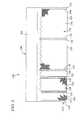
- FIG. 1is an isometric view of a shelter of the present invention.
- FIG. 2is a front elevational view of the shelter of FIG. 1 .
- FIG. 3Ais an isometric view of a roof assembly of a shelter of the present invention.
- FIG. 3Bis an isometric view of a frame assembly of a shelter of the present invention.
- FIG. 3Cis an isometric view of a flexible sidewall assembly of a shelter of the present invention.
- FIG. 4is a front elevational view of a second embodiment of a shelter of the present invention.
- FIG. 5is a front elevational view of a third embodiment of a shelter of the present invention.
- FIG. 6is a front elevational view of a fourth embodiment of a shelter of the present invention.
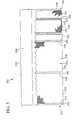
- FIG. 7is a somewhat schematic, front elevational view of a frame assembly of a shelter of the present invention.
- FIG. 8is a somewhat plan view of the frame assembly of FIG. 7 with parts removed for clarity.
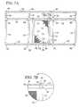
- FIG. 9is a somewhat schematic, top plan view of a tensioning device of the flexible sidewall assembly of the shelter of FIGS. 7 and 8.
- FIG. 10is a somewhat schematic top plan view of another tensioning device of the flexible sidewall assembly of the shelter of FIGS. 7 and 8.
- FIG. 11is a somewhat schematic, top plan view of another embodiment of a shelter of the present invention wherein the door opens inwardly.
- FIG. 12is a somewhat schematic, top plan view of another embodiment of the tensioning device of the flexible sidewall assembly of the shelter of FIG. 11 .
- FIG. 13is a somewhat schematic, top plan view of another embodiment of a tensioning device of the flexible sidewall assembly of the shelter of FIG. 11 .
- FIG. 14is a somewhat schematic, top plan view of a connection assembly of the flexible sidewall assembly of the shelter of FIG. 11 .
- FIG. 15is a somewhat schematic, top plan view of another embodiment of a shelter of the present invention with parts removed for clarity.
- FIGS. 16A and 16Bare isometric views of two alternative adjustable buckles used the in tensioning device of the flexible sidewall assembly of the shelter of the of FIG. 15 .
- a shelter 10 of the present inventioncomprises a fame assembly 12 , a roof assembly 14 , and a flexible sidewall assembly 16 .
- the frame assembly 12includes a plurality of upright frame members 18 laterally spaced relative to each other, and a plurality of lower lateral frame members 20 extending laterally between and interconnecting the upright frame members 18 .
- the lower lateral frame members 20prevent upright frame members 18 from moving laterally relative to each other.
- the flexible sidewall assembly 16includes a first sidewall frame 22 , and a second sidewall frame 24 .
- a flexible sidewall 26is connected at one end to the first sidewall frame 22 , and is connected at another end to the second sidewall frame 24 .
- the first sidewall frame 22is connectable to at least one of the upright frame members 18 and lower lateral fame members 20 .
- the second sidewall frame 24is connectable to at least one of the upright frame members 18 and lower lateral frame members 20 , and at a position laterally spaced relative to the first sidewall frame 22 , with the flexible sidewall extending therebetween.
- the flexible side wall assembly 16When connected to the frame assembly 12 , the flexible side wall assembly 16 is pulled taut such that it additionally secures the relative positions of the frame members and prevents their disassembly.
- the flexible side wall assembly 16can be wrapped around at least one of the first and second sidewall fines 22 or 24 for transportation or storage.
- the first sidewall frame 22 and second sidewall frame 24can form a door frame assembly 28 .
- the door frame assembly 28includes a door panel 30 extending between the first sidewall frame 22 and second sidewall frame 24 , and pivotally connected with a fastening means 32 to at least one of the first or second sidewall frames 22 or 24 .
- the first sidewall frame 22 and the second sidewall frame 24are each connected at one end to at least one lower lateral frame member 20 , and each connected at another end to at least one upper lateral frame member 34 spaced above the lower lateral frame member 20 .
- the first and second sidewall frames 22 and 24are laterally spaced relative to each other to define a door opening therebetween, over which the door panel 30 can extend.
- the frame assembly 12further includes a plurality of roof frame members 36 extending from one end upwardly at an angle from the upper lateral frame members 34 .
- the roof frame members 36are joined at a second end to peak lateral frame members 38 .
- the roof assembly 14comprises a roof cover 40 extending over the frame assembly 12 and connectable thereto.
- the frame assembly 12farther includes plurality of fittings 42 , 44 and 46 , and each fitting interconnects adjacent frame members by receiving the ends of the frame members. As shown typically in FIG. 2, each fitting includes a plurality of female recesses for receiving therein the ends of respective fame members to interconnect the frame members and form the fame assembly. Additionally, the fittings can slidably interconnect the respective frame members such that fasteners are not required to fixedly secure the respective fame members in relation to each other.
- the upright frame members 18are receivable within respective lower frame fittings 42 releaseably secured to lower lateral frame members 20 .
- Roof frame members 36 and upper lateral frame members 34are receivable within respective upper frame fittings 44 to thereby fixedly secure roof frame members 36 and upper lateral frame members 34 relative to each other.
- roof frame members 36 and peak lateral frame members 38are receivable within respective peak frame fittings 46 to thereby fixedly secure roof frame members 36 and peak lateral frame members 38 relative to each other.
- the Same assembly members and fittingscan be fabricated from rigid, durable, corrosion-resistant material, such as galvanized steel or a coated steel.
- the flexible sidewall 26 and door panel 30can be fabricated from many different flexible, durable materials, such as insect netting, chain link fence, or canvas for example.
- the roof cover 40can be fabricated from a water-proof, tear-resistant material, such as canvas, to provide overhead shelter.
- the fastening means 32 pivotally connecting at least one of the first and second sidewall frames 22 or 24 , and the door frame assembly 28can be one or more conventional hinges.
- the door panel 30can be connected to the hinges for pivotally moving the door panel between open and closed positions.
- FIGS. 3A through 3Cdelineate the principal assemblies of one embodiment of a shelter 10 of the present invention.
- the frame assembly 12includes eight upright frame members 18 laterally spaced relative to each other.
- the frame assembly 12further includes four lower lateral frame members 20 extending laterally between and interconnecting the upright frame members 18 .
- the upright frame members 18are slidably received within respective lower frame female fittings 42 secured to lower lateral frame members 20 .
- the frame assembly 12includes eight roof frame members 36 extending from one end upwardly at an angle from eight upper lateral frame members 34 .
- the roof frame members 36 and the upper lateral frame members 34are slidably received within respective upper frame fittings 44 , to thereby secure the roof frame members 36 and the upper lateral frame members 34 relative to each other.
- the roof frame members 36are joined at a second end to three peak lateral frame members 38 .
- the roof frame members 36 and the peak lateral frame members 38are slidably received within respective peak frame fittings 46 , to thereby secure the roof frame members 36 and the peak lateral frame members 38 relative to each other.
- all of the frame members 18 , 20 , 34 , 36 , and 38can be slidably removed from their respective frame fittings 42 , 44 , and 46 to permit disassembly of the frame assembly 12 for transportation or storage.
- the flexible sidewall assembly 16includes a flexible sidewall 26 extending between the first sidewall frame 22 and second sidewall frame 24 for enclosing the frame assembly 12 .
- the first sidewall fame 22 and second sidewall frame 24form the door frame assembly 28 .
- the door frame assembly 28includes a door panel 30 pivotally connected to the first sidewall frame 22 with three hinges 32 .
- the door frame assembly 28may further define a door frame 48 including upright frame members 50 and 52 , and upper and lower lateral frame members 54 and 56 connected therebetween to form a frame for the door panel 30 .
- the door frame assembly 28may include a handle 58 or like means for Rasping the door frame assembly 28 .
- the flexible side wall assembly 16 shown detached from the frame assembly 12 in FIG. 3Cis wrappable around at least one of the fist and second sidewall frames 22 or 24 for transportation or storage.
- the roof assembly 14 shown in FIG. 3Arests on and is releaseably secured to the frame assembly 12 by any one of numerous conventional means such as, for example, tie-down straps.
- FIGS. 4 through 6three alternative configurations of the shelter 10 of the present invention are indicated generally by the respective reference numerals 110 , 210 , and 310 .
- the shelters 110 , 210 , and 310are each the same as the shelter 10 described above with reference to FIGS. 1 through 3, and therefore like reference numerals preceded by the respective numeral “1”, “2”, and “3” are used to indicate like elements.
- one advantage of the tensioned sidewall assembly of the present inventionis that the door frame assembly can be positioned at any of a plurality of different locations on the frame assembly.
- the side wall assembly 116can be connected to the frame assembly 112 such that the door frame assembly 128 is positioned to the left of the front side of shelter 110 in relation to the front side of shelter 10 shown in FIGS. 1 through 3.
- the side wall assembly 216can be connected to the frame assembly 212 such that the door frame assembly 228 is positioned to the right of the front side of shelter 210 in relation to the front side of shelter 10 shown in FIGS. 1 through 3.
- the side wall assembly 316can be connected to the frame assembly 312 such that the door frame assembly 328 is positioned on a different side of shelter 310 in relation to the front side of the shelter 10 shown in FIGS. 1 through 3.
- the first sidewall frame 22 of the tensioned sidewall assemblyis connectable to at least one of the upright frame members 18 and lower lateral frame members 20 ; and the second sidewall frame 24 similarly is connectable to at least one of the upright frame members 18 and lower lateral frame members 20 , and at a position laterally spaced relative to the first sidewall frame 22 .
- One upright frame member 18is fabricated to slidably receive a first end of each first and second sidewall frame 22 and 24
- respective lower frame fittings 42can be fabricated to slidably receive a second end of each firs and second sidewall frames 22 and 24 to thereby connect each first and second sidewall frame 22 and 24 to at least one of the upright frame members 18 and lower lateral frame members 20 .
- upper lateral frame member 34defines an aperture 60 on one end, and a corresponding aperture 60 on the other end.
- a first end of each of the first and second sidewall frames 22 and 24are slidably received into and through the apertures 60 of the upper lateral frame member 34 .
- each of the first and second sidewall frames 22 and 24subsequently are slidably received within pective lower frame fittings 42 .
- the first end 62 of the first sidewall frame 22 as shown in FIG. 7B, or the first end of the second sidewall frame 24includes an aperture 64 for receiving any one of numerous known fastening means 66 , such as for example, a cotter pin, or a nut and bolt assembly.
- FIG. 8a plan view of a shelter 10 of the present invention is provided to show the positioning of one tensioning device 68 connected to a first end of the flexible sidewall 16 .
- the embodiment shown in FIG. 8also includes a second tensioning device 70 connected to a second end of the flexible sidewall 16 .
- Each tensioning device 68 or 70can secure the flexible sidewall 16 in a taut condition to the frame assembly 12 .
- each tensioning device 68 or 70defines a locked position fixedly securing the flexible sidewall 16 to the frame assembly 12 in a taut condition, and an unlocked position wherein the flexible sidewall 16 is movable relative to the frame assembly 12 .
- the tensioning device 68includes a roller 72 , wherein one end of the flexible sidewall 26 can be wrapped over the roller.
- the roller 72is approximately cylindrical as shown in FIG. 9 .
- the tensioning device 68further includes a locking member 74 which, as indicated by the arrows in FIG. 9, is movable relative to the roller 72 between a locked position engaging the flexible sidewall 26 and fixedly securing the flexible sidewall 26 in a taut condition; and an unlocked position spaced relative to the roller 72 and allowing the roller 72 and flexible sidewall 26 to move relative to the locking member 74 .
- the tensioning deviceincludes a housing 76 such that the roller 72 is rotatably mounted within the housing 76 , and the locking member 74 is connected between a housing sidewall 78 of the housing 76 and the roller 72 .
- the tensioning device 68also includes a threaded member 80 in the form of a thumb screw threadedly connected between the locking member 74 and housing 76 .
- the locking member 74is movable between the locked and the unlocked positions upon threadedly rotating the threaded member 80 relative to the housing 76 .
- the tensioning device 68includes means 82 connectable to the roller 72 for rotating the roller 72 and, in turn, winding the flexible sidewall 26 on the roller 72
- the means 82 connectable to the roller 72 for rotating the roller 72can include a tool 84 , such as an appropriately shaped wrench, and a corresponding aperture 86 formed in an end wall 88 of the roller 72 .
- the tool 84can be slidably received within the aperture 86 such that the roller 72 can be rotated to thereby wind the flexible sidewall 26 on the roller 72 .
- the housing sidewall 78 of the housing 76can be fabricated to additionally form a door stop 90 of the door frame assembly 28 .
- a corresponding tensioning device 70can be provided to fixedly secure a second end of the flexible sidewall 26 .
- the tensioning device 70is essentially the same as the tensioning device 68 described above with reference to FIG. 9, and therefore like reference numerals preceded by the numeral “4” are used to indicate like elements.
- a primary difference of the tensioning device 70is that the locking member 474 is located adjacent to the housing 476 rather than in between the housing 76 and the roller 72 .
- the tensioning device 70includes a roller 472 , rotatably mounted within the housing 476 , wherein one end of the flexible sidewall 426 can be fixedly secured over the roller 472 .
- the roller surface 492can define a plurality of recessed surface areas and adjacent raised surface areas that are engagable with the flexible sidewall 426 for facilitating securing the flexible sidewall 426 on the roller 472 .
- the tensioning device 70further includes a locking member 474 movable relative to the roller 472 and the housing 474 between a locked position engaging the flexible sidewall 426 and fixedly securing the flexible sidewall 426 in a taut condition; and an unlocked position spaced relative to the roller 472 and the housing 474 and allowing the roller 472 and flexible sidewall 426 to move relative to the locking member 474 .
- the tensioning device 70also includes a threaded member 480 , such as a thumb screw, threadedly connected between the locking member 474 and housing 476 .
- the locking member 474is movable between the locked and the unlocked positions upon threadedly rotating the threaded member 480 relative to the housing 476 .
- the tensioning device 70includes means 482 connectable to the roller 472 for rotating the roller 472 and, in turn, fixedly securing the flexible sidewall 426 on the roller 472 .
- the housing 76 of the tensioning device 68can be formed by the first sidewall frame 22 of the flexible sidewall assembly 16 .
- the housing 476 of the tensioning device 70can be formed by the second sidewall frame 24 of the flexible sidewall assembly 16 .
- FIG. 11a plan view of another embodiment of a shelter 10 of the present invention is provided to show an alternative arrangement of the door frame assembly 28 such that the door frame assembly 28 opens inwardly.
- the tensioning devices 568 and 570are essentially the same as the tensioning devices 68 and 70 described above with reference to FIGS. 9 and 10, and therefore like reference numerals precede by the numeral “5” are used to indicate like elements in FIGS. 11, 12 , and 13 .
- the tensioning device 568is essentially the same as the tensioning device 68 described above. However, in order for the housing 576 to similarly form a doorstop 590 , the housing 576 includes a second housing sidewall 594 as shown in FIG. 11 . Similarly, the tensioning device 570 is essentially the same as the tensioning device 70 described above. Again, in order for the housing 570 to similarly form a doorstop 590 , the housing 576 includes a second housing sidewall 596 as shown in FIG. 13 .
- a shelter 10 of the present inventionmay alternatively comprise first and second flexible side walls 602 and 604 .
- the first flexible side wall 602is connected on one end to the first sidewall frame 22
- the second flexible side wall. 604is connected on one end to the second sidewall Same 24 .
- the flexible sidewall assembly 16further comprises a sidewall connector assembly 600 connected to the other ends of the first and second flexible sidewalls 602 and 604 to thereby interconnect the flexible sidewalls 602 and 604 .
- the connector assembly 600includes at least one locking member 606 , and as indicated by the arrows, the locking member is movable between a locked position and an unlocked position.
- the locking member 606engages the respective end of a first and second flexible sidewall 602 or 604 to fixedly secure the flexible sidewall thereto.
- the unlocked positionthe locking member 606 is spaced away from the respective flexible sidewall 602 or 604 to release the sidewall therefrom.
- the connector assembly 600includes a housing 608 , and at least one roller 610 , and preferably a second roller 612 , rotatably mounted within the housing 608 .
- One end of a respective flexible sidewall 602 or 604can be wrapped against a roller 610 or 612 to wind the flexible sidewall onto the roller, and to release the flexible sidewall therefrom.
- Each roller 610 and 612further includes a roller surface 614 and a means 616 connectable to the rollers for rotating the rollers and fixedly securing the flexible sidewall 602 or 604 , all as described above.
- the connector assembly 600includes a threaded member 618 threadedly connected between the locking member 606 and housing 608 . As described above, the locking member 606 is movable between the locked and the unlocked positions upon threadedly rotating the threaded member 618 relative to the housing 608 .
- shelter 710includes a flexible sidewall assembly 716 that further includes at least one elongated pocket 802 on at least one end thereof, and preferably a second elongated pocket 804 on the other end thereof.
- the first and second sidewall frames 722 and 724are each received within a respective elongated pocket 802 or 804 .
- a tensioning device 806is connected to the flexible sidewall 726 , and receives a strap 808 connected to an upright frame member 718 . By pulling the strap 808 through the tensioning device 806 , tension is applied to the flexible sidewall 726 .
- any of the tensioning devices employed in a shelter of the present inventionmay take any of numerous different shapes, configurations, and/or types of such tensioning devices that are currently or later become known for performing the functions of the tensioning device assemblies described herein.
- a tensioning device 806alternatively can comprise an adjustable buckle 806 as shown in FIG. 16A and 16B.
- At least one strap 808can connect the adjustable buckle 806 between a respective end of the flexible sidewall 726 and an upright frame member 718 to thereby adjustably connect the flexible sidewall assembly 716 to the frame assembly.
- the adjustable bucklecan be any one of numerous embodiments known such as a spring-loaded buckle 812 shown in FIG. 16A, or a double bar buckle 810 shown in FIG. 16 B.
- One advantage of the flexible sidewall assembly described in connection with a shelter of the present inventionis that when it is pulled taut, the side wall assembly effectively secures the frame assembly members and prevents their disassembly
- Another advantage of the flexible sidewall assemblyis that a shelter can be fully assembled and secured without the use of fasteners, and be as effectively secured as if fasteners were employed.
Landscapes
- Engineering & Computer Science (AREA)
- Architecture (AREA)
- Civil Engineering (AREA)
- Structural Engineering (AREA)
- Tents Or Canopies (AREA)
Abstract
Description
Claims (26)
Priority Applications (1)
| Application Number | Priority Date | Filing Date | Title |
|---|---|---|---|
| US10/031,029US6684584B1 (en) | 1999-07-16 | 2000-07-17 | Shelter having a tensioned sidewall assembly |
Applications Claiming Priority (3)
| Application Number | Priority Date | Filing Date | Title |
|---|---|---|---|
| US14434199P | 1999-07-16 | 1999-07-16 | |
| US10/031,029US6684584B1 (en) | 1999-07-16 | 2000-07-17 | Shelter having a tensioned sidewall assembly |
| PCT/US2000/019313WO2001006069A1 (en) | 1999-07-16 | 2000-07-17 | Shelter with tensioned sidewall assembly |
Publications (1)
| Publication Number | Publication Date |
|---|---|
| US6684584B1true US6684584B1 (en) | 2004-02-03 |
Family
ID=30447799
Family Applications (1)
| Application Number | Title | Priority Date | Filing Date |
|---|---|---|---|
| US10/031,029Expired - Fee RelatedUS6684584B1 (en) | 1999-07-16 | 2000-07-17 | Shelter having a tensioned sidewall assembly |
Country Status (1)
| Country | Link |
|---|---|
| US (1) | US6684584B1 (en) |
Cited By (21)
| Publication number | Priority date | Publication date | Assignee | Title |
|---|---|---|---|---|
| US20030084934A1 (en)* | 2001-10-26 | 2003-05-08 | Goldwitz Brian L | Shelter with twist tight canopy and method for assembling same |
| US20050194031A1 (en)* | 2004-03-04 | 2005-09-08 | Tracy Forlini Goldwitz | System and method for storing, assembling and transporting a canopy |
| US20050194030A1 (en)* | 2004-02-27 | 2005-09-08 | Opac, Llc | Shelter having an extendable roof |
| US20060060831A1 (en)* | 2004-09-09 | 2006-03-23 | Cindy Lee Seas | Portable privacy panels |
| US20070295378A1 (en)* | 2004-11-04 | 2007-12-27 | Hal Lapping | Tent Frame fitted for Multiple Canopies |
| US20080163563A1 (en)* | 2006-09-29 | 2008-07-10 | Kevin Sciglia | Patio or pool enclosure with removable panels |
| US20090308422A1 (en)* | 2008-06-12 | 2009-12-17 | Scott Rizzotto | Outdoor spa covering device |
| US20100236158A1 (en)* | 2009-03-18 | 2010-09-23 | Peter Carbonaro | Apparatus for a wind resistant and post load re-tensioning system utilizing a composite fabric and attachment apparatus |
| US20100326485A1 (en)* | 2006-10-18 | 2010-12-30 | Wanda Ying Li | Outdoor canopy |
| US20110083371A1 (en)* | 2009-10-14 | 2011-04-14 | Hughes Brian G | Retractable screen door system |
| US20110146739A1 (en)* | 2005-11-01 | 2011-06-23 | Wanda Ying Li | Outdoor Canopy |
| USD654187S1 (en) | 2010-03-02 | 2012-02-14 | Shelterlogic Corp. | Shelter |
| US8646222B2 (en) | 2010-03-18 | 2014-02-11 | Windwrap, Inc. | Building construction wrapped with reinforcement fabric to resist wind loading |
| US8875772B1 (en)* | 2011-06-21 | 2014-11-04 | Nicholas E. Dixon, Jr. | Access door unit and method of installing door unit |
| US9295900B1 (en) | 2012-06-19 | 2016-03-29 | Nicholas E. Dixon, Jr. | Access door unit |
| US10364568B2 (en)* | 2015-01-23 | 2019-07-30 | Richard Kramer | Fabricated building |
| US11473362B2 (en)* | 2019-11-12 | 2022-10-18 | Randy Caulder | Board apparatus |
| US20220412118A1 (en)* | 2019-11-19 | 2022-12-29 | Kenneth L. Licau | Modular Tent System With Removable Roof And Floor |
| US20230304290A1 (en)* | 2021-05-26 | 2023-09-28 | S.W. Engineering Inc. | System and method of securing a roof truss to a load-bearing wall |
| US12359458B2 (en) | 2020-11-23 | 2025-07-15 | Peter Frank Carbonaro | Apparatus for unifying structural continuous load paths and reinforcing a roofing structural system utilizing super high tensile strength tape and plastic attachment mechanisms |
| USD1087274S1 (en)* | 2023-03-06 | 2025-08-05 | Shandong New Age Trading Co., Ltd. | Tent |
Citations (21)
| Publication number | Priority date | Publication date | Assignee | Title |
|---|---|---|---|---|
| US1262564A (en) | 1918-03-01 | 1918-04-09 | Marvin L Reynolds | Portable building. |
| US1650323A (en) | 1924-07-21 | 1927-11-22 | Byars Edgar | Foldable and rollable tent |
| US2022211A (en) | 1934-05-02 | 1935-11-26 | Geo B Carpenter & Co | Portable lawn canopy |
| US2448895A (en) | 1945-04-25 | 1948-09-07 | John T Lawrence | Collapsible house |
| US2493749A (en) | 1945-08-11 | 1950-01-10 | Walter R Brown | Sectional hospital tent |
| US2837153A (en) | 1955-12-02 | 1958-06-03 | Harold H Brown | Metallic building wall |
| US2856941A (en) | 1957-03-19 | 1958-10-21 | Earl C O'neal | Portable garage |
| US2865386A (en) | 1956-07-20 | 1958-12-23 | John M Burns | Collapsible structure |
| US2905281A (en) | 1951-08-02 | 1959-09-22 | Alumatic Corp Of America | Porch or garden house enclosure |
| US2986150A (en) | 1958-03-17 | 1961-05-30 | Torian William Harold | Means for mounting thin, flexible membranes |
| US3055380A (en) | 1959-10-02 | 1962-09-25 | Eugene A Benka | Folding tent |
| US3222841A (en) | 1962-10-08 | 1965-12-14 | Aire Lite Ind Inc | Screen enclosure |
| US3957069A (en) | 1975-04-07 | 1976-05-18 | Salvatore Denaro | Expandible plugs for securing a tent |
| US4817655A (en)* | 1986-12-16 | 1989-04-04 | Abc Extrusion Company | Canopy assembly |
| US5224306A (en) | 1991-11-13 | 1993-07-06 | Gallagher-Kaiser Corporation | Enclosure assembly |
| US5520236A (en) | 1993-10-26 | 1996-05-28 | Speedling, Inc. | Greenhouse curtain system |
| US5617681A (en) | 1995-04-14 | 1997-04-08 | Lyons; Richard D. | Free-standing outdoor enclosure |
| US5800106A (en)* | 1996-12-09 | 1998-09-01 | Miller; Bradley A. | Adjustable magnetic cargo strap system |
| US5845423A (en)* | 1996-01-25 | 1998-12-08 | Hicks; Charles H. | Advetising substrate attachable to trucks |
| US5944085A (en)* | 1995-03-22 | 1999-08-31 | White Consolidated Industries, Inc. | Retractable awning with improved assembly features |
| US6431315B1 (en)* | 2000-10-23 | 2002-08-13 | K D L Outdoor Products, Inc. | Tree step with strap attachment |
- 2000
- 2000-07-17USUS10/031,029patent/US6684584B1/ennot_activeExpired - Fee Related
Patent Citations (21)
| Publication number | Priority date | Publication date | Assignee | Title |
|---|---|---|---|---|
| US1262564A (en) | 1918-03-01 | 1918-04-09 | Marvin L Reynolds | Portable building. |
| US1650323A (en) | 1924-07-21 | 1927-11-22 | Byars Edgar | Foldable and rollable tent |
| US2022211A (en) | 1934-05-02 | 1935-11-26 | Geo B Carpenter & Co | Portable lawn canopy |
| US2448895A (en) | 1945-04-25 | 1948-09-07 | John T Lawrence | Collapsible house |
| US2493749A (en) | 1945-08-11 | 1950-01-10 | Walter R Brown | Sectional hospital tent |
| US2905281A (en) | 1951-08-02 | 1959-09-22 | Alumatic Corp Of America | Porch or garden house enclosure |
| US2837153A (en) | 1955-12-02 | 1958-06-03 | Harold H Brown | Metallic building wall |
| US2865386A (en) | 1956-07-20 | 1958-12-23 | John M Burns | Collapsible structure |
| US2856941A (en) | 1957-03-19 | 1958-10-21 | Earl C O'neal | Portable garage |
| US2986150A (en) | 1958-03-17 | 1961-05-30 | Torian William Harold | Means for mounting thin, flexible membranes |
| US3055380A (en) | 1959-10-02 | 1962-09-25 | Eugene A Benka | Folding tent |
| US3222841A (en) | 1962-10-08 | 1965-12-14 | Aire Lite Ind Inc | Screen enclosure |
| US3957069A (en) | 1975-04-07 | 1976-05-18 | Salvatore Denaro | Expandible plugs for securing a tent |
| US4817655A (en)* | 1986-12-16 | 1989-04-04 | Abc Extrusion Company | Canopy assembly |
| US5224306A (en) | 1991-11-13 | 1993-07-06 | Gallagher-Kaiser Corporation | Enclosure assembly |
| US5520236A (en) | 1993-10-26 | 1996-05-28 | Speedling, Inc. | Greenhouse curtain system |
| US5944085A (en)* | 1995-03-22 | 1999-08-31 | White Consolidated Industries, Inc. | Retractable awning with improved assembly features |
| US5617681A (en) | 1995-04-14 | 1997-04-08 | Lyons; Richard D. | Free-standing outdoor enclosure |
| US5845423A (en)* | 1996-01-25 | 1998-12-08 | Hicks; Charles H. | Advetising substrate attachable to trucks |
| US5800106A (en)* | 1996-12-09 | 1998-09-01 | Miller; Bradley A. | Adjustable magnetic cargo strap system |
| US6431315B1 (en)* | 2000-10-23 | 2002-08-13 | K D L Outdoor Products, Inc. | Tree step with strap attachment |
Cited By (32)
| Publication number | Priority date | Publication date | Assignee | Title |
|---|---|---|---|---|
| US6994099B2 (en) | 2001-10-26 | 2006-02-07 | Opac, Llc | Shelter with twist tight canopy and method for assembling same |
| US20030084934A1 (en)* | 2001-10-26 | 2003-05-08 | Goldwitz Brian L | Shelter with twist tight canopy and method for assembling same |
| US20050194030A1 (en)* | 2004-02-27 | 2005-09-08 | Opac, Llc | Shelter having an extendable roof |
| US20090056779A1 (en)* | 2004-02-27 | 2009-03-05 | Shelterlogic, Llc | Auxiliary section for a canopy |
| US20090293927A1 (en)* | 2004-02-27 | 2009-12-03 | Shelterlogic Llc | Shelter having an extendable roof |
| US20050194031A1 (en)* | 2004-03-04 | 2005-09-08 | Tracy Forlini Goldwitz | System and method for storing, assembling and transporting a canopy |
| US7296584B2 (en) | 2004-03-04 | 2007-11-20 | Shelterlogic Llc | System and method for storing, assembling and transporting a canopy |
| US20080035194A1 (en)* | 2004-03-04 | 2008-02-14 | Shelterlogic, Llc | System and method for storing, assembling and transporting a canopy |
| US20060060831A1 (en)* | 2004-09-09 | 2006-03-23 | Cindy Lee Seas | Portable privacy panels |
| US20070295378A1 (en)* | 2004-11-04 | 2007-12-27 | Hal Lapping | Tent Frame fitted for Multiple Canopies |
| US20110146739A1 (en)* | 2005-11-01 | 2011-06-23 | Wanda Ying Li | Outdoor Canopy |
| US8118045B2 (en)* | 2005-11-01 | 2012-02-21 | Wanda Ying Li | Outdoor canopy |
| US20080163563A1 (en)* | 2006-09-29 | 2008-07-10 | Kevin Sciglia | Patio or pool enclosure with removable panels |
| US20100326485A1 (en)* | 2006-10-18 | 2010-12-30 | Wanda Ying Li | Outdoor canopy |
| US20090308422A1 (en)* | 2008-06-12 | 2009-12-17 | Scott Rizzotto | Outdoor spa covering device |
| US20100236158A1 (en)* | 2009-03-18 | 2010-09-23 | Peter Carbonaro | Apparatus for a wind resistant and post load re-tensioning system utilizing a composite fabric and attachment apparatus |
| US8910436B2 (en) | 2009-03-18 | 2014-12-16 | Windwrap, Inc. | Apparatus for a wind resistant and post load re-tensioning system utilizing a composite fabric and attachment apparatus |
| US8631615B2 (en) | 2009-03-18 | 2014-01-21 | Windwrap, Inc. | Apparatus for a wind resistant and post load re-tensioning system utilizing a composite fabric and attachment apparatus |
| US20110083371A1 (en)* | 2009-10-14 | 2011-04-14 | Hughes Brian G | Retractable screen door system |
| USD654187S1 (en) | 2010-03-02 | 2012-02-14 | Shelterlogic Corp. | Shelter |
| US8646222B2 (en) | 2010-03-18 | 2014-02-11 | Windwrap, Inc. | Building construction wrapped with reinforcement fabric to resist wind loading |
| US8943761B2 (en) | 2010-03-18 | 2015-02-03 | Windwrap, Inc. | Building construction wrapped with reinforcement fabric to resist wind loading |
| US8875772B1 (en)* | 2011-06-21 | 2014-11-04 | Nicholas E. Dixon, Jr. | Access door unit and method of installing door unit |
| US9295900B1 (en) | 2012-06-19 | 2016-03-29 | Nicholas E. Dixon, Jr. | Access door unit |
| US10364568B2 (en)* | 2015-01-23 | 2019-07-30 | Richard Kramer | Fabricated building |
| US11473362B2 (en)* | 2019-11-12 | 2022-10-18 | Randy Caulder | Board apparatus |
| US20220412118A1 (en)* | 2019-11-19 | 2022-12-29 | Kenneth L. Licau | Modular Tent System With Removable Roof And Floor |
| US12258771B2 (en)* | 2019-11-19 | 2025-03-25 | Kenneth L. Licau | Modular tent system with removable roof and floor |
| US12359458B2 (en) | 2020-11-23 | 2025-07-15 | Peter Frank Carbonaro | Apparatus for unifying structural continuous load paths and reinforcing a roofing structural system utilizing super high tensile strength tape and plastic attachment mechanisms |
| US20230304290A1 (en)* | 2021-05-26 | 2023-09-28 | S.W. Engineering Inc. | System and method of securing a roof truss to a load-bearing wall |
| US11927010B2 (en)* | 2021-05-26 | 2024-03-12 | S.W. Engineering Inc. | System and method of securing a roof truss to a load-bearing wall |
| USD1087274S1 (en)* | 2023-03-06 | 2025-08-05 | Shandong New Age Trading Co., Ltd. | Tent |
Similar Documents
| Publication | Publication Date | Title |
|---|---|---|
| US6684584B1 (en) | Shelter having a tensioned sidewall assembly | |
| US6948280B2 (en) | Assembleable and towable/trailerable ice fishing shanty/hunting blind | |
| US9771729B2 (en) | Modular frame and structure system | |
| US6505638B1 (en) | Canopy structure | |
| US7472666B1 (en) | Support frame for tarpaulin used for sheltering boats and other objects | |
| US8096312B2 (en) | Erectable shelter with three way awning | |
| EP0795068B1 (en) | Temporary protective covering system | |
| US20030209208A1 (en) | Portable corral apparatus | |
| US20070252125A1 (en) | Modular fencing system | |
| US12091874B2 (en) | Portable and versatile tent with bed | |
| DE2548705A1 (en) | SUB-FRAME AND TENT FRAME AND TENT FORMED WITH IT | |
| US8979157B2 (en) | Removable enclosure for rear of vehicle | |
| US5655340A (en) | Stable open-sided shelter | |
| DE2951016A1 (en) | CAMPING TENT UNIT | |
| US20090032078A1 (en) | Collapsible walkway cover system | |
| CA2379067C (en) | Shelter with tensioned sidewall assembly | |
| US20160332556A1 (en) | Easy tent | |
| DE3884202T2 (en) | Structure for assembling and disassembling shelters, especially roofs. | |
| GB2382594A (en) | Portable loose boxes or stalls with fabric roof | |
| DE2751561A1 (en) | Anchor-less tent fitted to motor car roof - consists of two half bowls folding open to make level platform and material supported by stays to make upper tent walls | |
| US12312823B2 (en) | Portable multi-hinged shelter | |
| US20250283346A1 (en) | Rooftop tent annex system | |
| DE20217359U1 (en) | Clamping strap for the fastening of load on vehicle has on loose end of strap male and female pieces of hook and loop fastener fitted on opposite sides of strap | |
| AU2005100129A4 (en) | A door assembly | |
| JPS5825403Y2 (en) | Signboard mounting frame for utility poles |
Legal Events
| Date | Code | Title | Description |
|---|---|---|---|
| AS | Assignment | Owner name:GOLDWITZ, TRACY, CONNECTICUT Free format text:ASSIGNMENT OF ASSIGNORS INTEREST;ASSIGNOR:GOLDWITZ, BRIAN L.;REEL/FRAME:012718/0701 Effective date:20020220 | |
| AS | Assignment | Owner name:NORTH AMERICAN OUTDOOR PRODUCTS, LLC, CONNECTICUT Free format text:ASSIGNMENT OF ASSIGNORS INTEREST;ASSIGNOR:GOLDWITZ, TRACY FORLINI;REEL/FRAME:016153/0222 Effective date:20041221 | |
| AS | Assignment | Owner name:OPAC, LLC, CONNECTICUT Free format text:ASSIGNMENT OF ASSIGNORS INTEREST;ASSIGNOR:NORTH AMERICAN OUTDOOR PRODUCTS, LLC;REEL/FRAME:016153/0108 Effective date:20041221 | |
| AS | Assignment | Owner name:NEWSTAR CP FUNDING LLC, MASSACHUSETTS Free format text:SECURITY AGREEMENT;ASSIGNORS:OPAC, LLC;SHELTERWORKZ, LLC;OPCAC, LLC;AND OTHERS;REEL/FRAME:015629/0580 Effective date:20050112 | |
| AS | Assignment | Owner name:LEGG MASON SBIC MEZZANINE FUND, L.P., MARYLAND Free format text:SECURITY AGREEMENT;ASSIGNORS:OPAC, LLC;SHELTERWORKZ, LLC;OPCAC, LLC;AND OTHERS;REEL/FRAME:015756/0135 Effective date:20050112 Owner name:MERION INVESTMENT PARTNERS, L.P., PENNSYLVANIA Free format text:SECURITY AGREEMENT;ASSIGNORS:OPAC, LLC;SHELTERWORKZ, LLC;OPCAC, LLC;AND OTHERS;REEL/FRAME:015756/0135 Effective date:20050112 | |
| AS | Assignment | Owner name:SHELTERLOGIC LLC, CONNECTICUT Free format text:RELEASE BY SECURED PARTY;ASSIGNORS:MERION INVESTMENT PARTNERS, L.P.;LEGG MASON SBIC MEZZANINE FUND, L.P.;REEL/FRAME:018385/0312 Effective date:20061011 Owner name:SHELTERLOGIC HOLDINGS LLC, CONNECTICUT Free format text:RELEASE BY SECURED PARTY;ASSIGNORS:MERION INVESTMENT PARTNERS, L.P.;LEGG MASON SBIC MEZZANINE FUND, L.P.;REEL/FRAME:018385/0312 Effective date:20061011 Owner name:SHELTERLOGIC INTERNATIONAL LLC, CONNECTICUT Free format text:RELEASE BY SECURED PARTY;ASSIGNORS:MERION INVESTMENT PARTNERS, L.P.;LEGG MASON SBIC MEZZANINE FUND, L.P.;REEL/FRAME:018385/0312 Effective date:20061011 Owner name:NORTH AMERICAN A L.L.C., CONNECTICUT Free format text:RELEASE BY SECURED PARTY;ASSIGNORS:MERION INVESTMENT PARTNERS, L.P.;LEGG MASON SBIC MEZZANINE FUND, L.P.;REEL/FRAME:018385/0312 Effective date:20061011 Owner name:ALBION MEZZANINE FUND II, L.P., NEW YORK Free format text:SECURITY AGREEMENT;ASSIGNORS:SHELTERLOGIC LLC;SHELTERLOGIC HOLDINGS LLC;SHELTERLOGIC INTERNATIONAL LLC;AND OTHERS;REEL/FRAME:018385/0327 Effective date:20061011 Owner name:NEWSTAR FINANCIAL, INC., AS ADMINISTRATIVE AGENT A Free format text:SECURITY AGREEMENT;ASSIGNORS:SHELTERLOGIC LLC;SHELTERLOGIC HOLDINGS LLC;SHELTERLOGIC INTERNATIONAL LLC;AND OTHERS;REEL/FRAME:018385/0320 Effective date:20061011 | |
| REMI | Maintenance fee reminder mailed | ||
| LAPS | Lapse for failure to pay maintenance fees | ||
| STCH | Information on status: patent discontinuation | Free format text:PATENT EXPIRED DUE TO NONPAYMENT OF MAINTENANCE FEES UNDER 37 CFR 1.362 | |
| FP | Lapsed due to failure to pay maintenance fee | Effective date:20080203 | |
| AS | Assignment | Owner name:SHELTERLOGIC LLC,CONNECTICUT Free format text:RELEASE BY SECURED PARTY;ASSIGNOR:NEWSTAR FINANCIAL, INC. AS ADMINISTRATIVE AGENT AND COLLATERAL AGENT;REEL/FRAME:024515/0112 Effective date:20100527 Owner name:SHELTERLOGIC HOLDINGS LLC,CONNECTICUT Free format text:RELEASE BY SECURED PARTY;ASSIGNOR:NEWSTAR FINANCIAL, INC. AS ADMINISTRATIVE AGENT AND COLLATERAL AGENT;REEL/FRAME:024515/0112 Effective date:20100527 Owner name:SHELTERLOGIC INTERNATIONAL LLC,CONNECTICUT Free format text:RELEASE BY SECURED PARTY;ASSIGNOR:NEWSTAR FINANCIAL, INC. AS ADMINISTRATIVE AGENT AND COLLATERAL AGENT;REEL/FRAME:024515/0112 Effective date:20100527 Owner name:NORTH AMERICAN A L.L.C.,CONNECTICUT Free format text:RELEASE BY SECURED PARTY;ASSIGNOR:NEWSTAR FINANCIAL, INC. AS ADMINISTRATIVE AGENT AND COLLATERAL AGENT;REEL/FRAME:024515/0112 Effective date:20100527 Owner name:SHELTERLOGIC LLC, CONNECTICUT Free format text:RELEASE BY SECURED PARTY;ASSIGNOR:NEWSTAR FINANCIAL, INC. AS ADMINISTRATIVE AGENT AND COLLATERAL AGENT;REEL/FRAME:024515/0112 Effective date:20100527 Owner name:SHELTERLOGIC HOLDINGS LLC, CONNECTICUT Free format text:RELEASE BY SECURED PARTY;ASSIGNOR:NEWSTAR FINANCIAL, INC. AS ADMINISTRATIVE AGENT AND COLLATERAL AGENT;REEL/FRAME:024515/0112 Effective date:20100527 Owner name:SHELTERLOGIC INTERNATIONAL LLC, CONNECTICUT Free format text:RELEASE BY SECURED PARTY;ASSIGNOR:NEWSTAR FINANCIAL, INC. AS ADMINISTRATIVE AGENT AND COLLATERAL AGENT;REEL/FRAME:024515/0112 Effective date:20100527 Owner name:NORTH AMERICAN A L.L.C., CONNECTICUT Free format text:RELEASE BY SECURED PARTY;ASSIGNOR:NEWSTAR FINANCIAL, INC. AS ADMINISTRATIVE AGENT AND COLLATERAL AGENT;REEL/FRAME:024515/0112 Effective date:20100527 | |
| AS | Assignment | Owner name:SHELTERLOGIC LLC, CONNECTICUT Free format text:RELEASE BY SECURED PARTY;ASSIGNOR:NEWSTAR CP FUNDING LLC;REEL/FRAME:026804/0069 Effective date:20110824 | |
| AS | Assignment | Owner name:NORTH AMERICAN A L.L.C., CONNECTICUT Free format text:RELEASE BY SECURED PARTY;ASSIGNOR:ALBION MEZZANINE FUND II L.P., AS AGENT;REEL/FRAME:026826/0296 Effective date:20110826 Owner name:SHELTERLOGIC HOLDINGS LLC, CONNECTICUT Free format text:RELEASE BY SECURED PARTY;ASSIGNOR:SOVEREIGN BANK;REEL/FRAME:026827/0226 Effective date:20110826 Owner name:SHELTERLOGIC LLC, CONNECTICUT Free format text:RELEASE BY SECURED PARTY;ASSIGNOR:SOVEREIGN BANK;REEL/FRAME:026827/0226 Effective date:20110826 Owner name:SHELTERLOGIC HOLDINGS LLC, CONNECTICUT Free format text:RELEASE BY SECURED PARTY;ASSIGNOR:ALBION MEZZANINE FUND II L.P., AS AGENT;REEL/FRAME:026826/0296 Effective date:20110826 Owner name:NORTH AMERICAN A L.L.C., CONNECTICUT Free format text:RELEASE BY SECURED PARTY;ASSIGNOR:SOVEREIGN BANK;REEL/FRAME:026827/0226 Effective date:20110826 Owner name:SHELTERLOGIC INTERNATIONAL LLC, CONNECTICUT Free format text:RELEASE BY SECURED PARTY;ASSIGNOR:SOVEREIGN BANK;REEL/FRAME:026827/0226 Effective date:20110826 Owner name:SHELTERLOGIC LLC, CONNECTICUT Free format text:RELEASE BY SECURED PARTY;ASSIGNOR:ALBION MEZZANINE FUND II L.P., AS AGENT;REEL/FRAME:026826/0296 Effective date:20110826 | |
| AS | Assignment | Owner name:SHELTERLOGIC CORP., CONNECTICUT Free format text:ASSIGNMENT OF ASSIGNORS INTEREST;ASSIGNOR:SHELTERLOGIC, LLC;REEL/FRAME:026834/0292 Effective date:20110826 |