US6684102B1 - Implantable heart monitors having capacitors with endcap headers - Google Patents
Implantable heart monitors having capacitors with endcap headersDownload PDFInfo
- Publication number
- US6684102B1 US6684102B1US09/706,515US70651500AUS6684102B1US 6684102 B1US6684102 B1US 6684102B1US 70651500 AUS70651500 AUS 70651500AUS 6684102 B1US6684102 B1US 6684102B1
- Authority
- US
- United States
- Prior art keywords
- patient
- management device
- capacitive element
- rhythm management
- heart rhythm
- Prior art date
- Legal status (The legal status is an assumption and is not a legal conclusion. Google has not performed a legal analysis and makes no representation as to the accuracy of the status listed.)
- Expired - Lifetime, expires
Links
Images


Classifications
- A—HUMAN NECESSITIES
- A61—MEDICAL OR VETERINARY SCIENCE; HYGIENE
- A61N—ELECTROTHERAPY; MAGNETOTHERAPY; RADIATION THERAPY; ULTRASOUND THERAPY
- A61N1/00—Electrotherapy; Circuits therefor
- A61N1/18—Applying electric currents by contact electrodes
- A61N1/32—Applying electric currents by contact electrodes alternating or intermittent currents
- A61N1/38—Applying electric currents by contact electrodes alternating or intermittent currents for producing shock effects
- A61N1/39—Heart defibrillators
- A61N1/3968—Constructional arrangements, e.g. casings
Definitions
- the present inventionconcerns capacitors, particularly wet-electrolytic capacitors used in implantable medical devices, such as implantable defibrillators, cardioverters, and pacemakers.
- the present inventionconcerns implantable heart monitors, such as defibrillators and cardioverters, particularly structures and methods for capacitors in such devices.
- the typical defibrillator or cardioverterincludes a set of electrical leads, which extend from a sealed housing into the walls of a heart after implantation. Within the housing are a battery for supplying power, monitoring circuitry for detecting abnormal heart rhythms, and a capacitor for delivering bursts of electric current through the leads to the heart.
- the capacitoris often times a cylindrical aluminum wet electrolytic capacitor.
- This type capacitorusually includes stacked strips of aluminum foil and paper rolled, or wound, to form a cylindrical structure which is housed in a round tubular aluminum can.
- the canhas an integral aluminum bottom end and an open top end sealed with a non-conductive flat circular lid, known as a header.
- Two terminalsextend from the header, each connected to one of the rolled aluminum foils.
- the inventors recognized with these cylindrical capacitorsis the overall height of the capacitor, measured from the bottom of the tubular aluminum can to the top of the terminals extending from the header.
- the terminalsare rigid metal structures that generally require clearance space to avoid contacting other components within the housing of the implantable devices. Providing this clearance space ultimately increases the size of implantable devices beyond that otherwise necessary.
- Another related problemis that the diameter of the header has a practical minimum of about twelve millimeters and thus restricts how small capacitors and thus implantable devices can be made. Accordingly, the inventors identified a need to develop space-efficient techniques and structures for providing terminals on electrolytic capacitors.
- One exemplary capacitorincludes two conductive endcaps at opposite ends of its capacitive element, instead of two upright terminals at one end, thereby allowing reduction in the height or volume of the capacitor and/or increases in the dimensions of other components, such as aluminum foils.
- Another exemplary capacitorincludes two feedthrough assemblies at opposite ends of the wound capacitive element to also facilitate reduction in the height or volume of the capacitor or increasing its energy-storage density.
- an implantable heart monitorsuch as a pacemaker, defibrillator, congestive-heart-failure (CHF) device, or cardioverter defibrillator, that incorporates one or more capacitors with the unique connection structures.
- a pacemakersuch as a pacemaker, defibrillator, congestive-heart-failure (CHF) device, or cardioverter defibrillator, that incorporates one or more capacitors with the unique connection structures.
- CHFcongestive-heart-failure
- cardioverter defibrillatorthat incorporates one or more capacitors with the unique connection structures.
- FIG. 1is a perspective view of an exemplary cylindrical wet electrolytic capacitor 100 embodying teachings of the present invention.
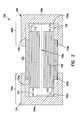
- FIG. 2is a cross-sectional view of capacitor 100 in FIG. 1 taken along line 2 — 2 .
- FIG. 3is a perspective view of an exemplary cylindrical wet electrolytic capacitor 300 embodying teachings of the present invention.
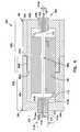
- FIG. 4is a cross-sectional view of capacitor 300 taken along line 4 — 4 in FIG. 3 .
- FIG. 5is a block diagram of an exemplary implantable heart monitor 500 which includes one or more electrolytic capacitors 532 embodying teachings of the present invention.
- FIGS. 1-5describes and illustrates one or more specific embodiments of the invention. These embodiments, offered not to limit but only to exemplify and teach, are shown and described in sufficient detail to enable those skilled in the art to implement or practice the invention. Thus, where appropriate to avoid obscuring the invention, the description may omit certain information known to those of skill in the art.
- FIG. 1shows a perspective view of an exemplary cylindrical wet electrolytic capacitor 100 which embodies teachings of the present invention.
- FIG. 2shows a cross-section of capacitor 100 taken along line 2 - 2 .
- capacitor 100includes a cylindrical or tubular section 102 , cylindrical endcaps 104 and 106 , a cylindrical capacitive element 108 , anode tab 110 , and cathode tab 112 .
- Tubular section 102which comprises a non-conductive material, such as a ceramic, a polymer, or a plastic, in the exemplary embodiment, at least partially encloses a central portion of wound or rolled capacitive element 108 .
- section 102has two opposing ends 102 a and 102 b that mate respectively with conductive end caps 104 and 106 .
- Endcaps 104 and 106which are exemplarily formed of diecast (deep drawn) or machined aluminum or other conductive metal compatible with the capacitive element, are generally hemispherical or concave (cup-like) in structure, comprising respective planar end portions 104 a and 106 a and respective annular or tubular portions 104 b and 106 b .
- Tubular portions 104 b and 106 bhave respective interior annular shoulders 104 c and 106 c , which abut respective ends 102 a and 102 b of tubular section 102 , and also allow portions 104 b and 106 b to overlap corresponding portions of section 102 .
- portions 104 b and 106 bmate with section 102 via a compound butt and lap joint.
- other embodimentsomit annular shoulders 104 c and 106 c , and include threads on the interior of portions 104 b and 106 b and on the exterior of corresponding portions section 102 .
- Other embodimentsuse other complementary joint structures and/or adhesives, epoxies, or other sealing compounds.
- Endcap 104is coupled via anode tab 110 to one or more anodic layers within capacitive element 108
- endcap 106is coupled via cathode tab 112 to a second conductive layer within the capacitive element. More particularly, anode tab 110 contacts an interior surface 104 d of endcap 104 , and cathode tab 112 contacts an interior surface 106 d of endcap 106 . Interior surfaces 104 d and 106 d are separated by respective distances 107 and 109 from capacitive element 108 to prevent the tabs from shorting with other parts of the capacitive element.
- tabs 110 and 112are welded respectively to surfaces 104 d and 106 d , and distances 107 and 109 are both approximately 0.02 inches (0.508 millimeters.) Some embodiments attach the tabs using conductive adhesives. Other embodiments reduce one or both of distances 107 and 109 by increasing the end margins of separators in capacitive element 108 and/or placing one or more insulative inserts between surface 104 d and the capacitive element or between surface 106 d and the capacitive element.
- Capacitive element 108includes an anode, a cathode, one or more inner separators, and two or more outer separators.
- the one or more inner separatorsare sandwiched between the anode and the cathode, and the resulting anode-separator-cathode sandwich is itself sandwiched between the outer separators.
- the anodecomprises three etched foils; the cathode comprises a single etched foil; and the separators comprise electrolyte-impregnated kraft paper.
- Exemplary foil materialsinclude aluminum, tantalum, hafnium, niobium, titanium, zirconium, and combinations of these metals, and exemplary foil structures include core-etched, tunnel-etched, and perforated-core-etched foils.
- FIGS. 3 and 4show an exemplary capacitor 300 , which also embodies teachings of the present invention. Specifically, FIG. 3 shows a perspective view of capacitor 300 , and FIG. 4 shows a cross-section of the capacitor taken along line 4 — 4 .
- capacitor 300which is similar in many respects to capacitor 100 in FIGS. 1 and 2, includes cylindrical endcaps 104 and 106 , cylindrical capacitive element 108 , anode tab 110 , and cathode tab 112 .
- cylindrical endcaps 104 and 106cylindrical capacitive element 108
- anode tab 110cylindrical capacitive element 108
- cathode tab 112cathode tab 112 .
- capacitor 300omits tubular section 102 , by forming a conductive interface 402 between endcaps 104 and 106 .
- Endcaps 104 and 106include respective planar end portions 104 a and 106 a and respective annular or tubular portions 104 b and 106 b .
- Tubular portions 104 binclude an interior annular shoulder 104 c which mates with a complementary exterior annular shoulder 106 c of tubular portion 106 b , forming interface 402 .
- the exemplary embodimentseals an exterior portion 402 a of the interface with an adhesive, such as an epoxy, or with a circumferential weld.
- an adhesivesuch as an epoxy
- Other embodimentsform middle portion 402 b of the interface with threads on corresponding portions of tubular portions 104 b and 106 b .
- Still other embodimentsomit annular shoulders 104 c and 106 c , welding, gluing, and or screwing tubular portions 104 b and 106 b together.
- Embodiments that omit shoulders 104 c and 106 clack portions 402 a and 402 b of interface 402 .
- Planar end portions 104 a and 106 ainclude respective holes 104 h and 106 h for respective feedthrough assemblies 410 and 420 .
- Feedthrough assembly 410includes a generally cylindrical insulative member 412 and a feedthrough conductor 414 .
- Insulative member 412includes an exterior face 412 a , an interior face 412 b , and a hole 412 h which extends from face 412 a to face 412 b .
- Insulative member 412has an exterior diameter (or more generally dimension) 412 d for establishing an interference fit with hole 104 h .
- the insulative memberis secured in place by brazing the insulative member to the perimeter of hole 104 h .
- Some other embodimentsweld a short metallic collar or sleeve to the case around the hole, insert the insulative member into the sleeve, and braze the insulative member to the sleeve and/or the feedthrough conductor.
- the sleevecan be made of aluminum or other metal compatible with the capacitor.
- Extending through hole 104 his a longitudinal shank portion 414 a of feedthrough conductor 414 .
- Shank portion 414 ahas a diameter or dimension 414 d .
- Conductor 414 aalso has an integral disk-shaped head portion 414 b which abuts interior face 412 b of insulative member 412 .
- An opposite side of head portion 414 bis welded to anode tab 110 , electrically coupling the feedthrough conductor to one or more anodes in capacitive element 108 .
- the exemplary embodimentsforms insulative member 412 from glass, plastic, epoxy, or rubber and feedthrough conductor 414 from aluminum or other conductive material compatible with capacitive element 108 . Additionally, it may be possible to size hole 104 h , insulative member 412 , hole 412 h , and feedthrough conductor diameter 414 d to cooperate with each other in establishing the interference fit between hole 104 h and insulative member 412 . Other embodiments epoxy the insulative member in place. Other embodiments mount the insulative member within hole 104 h and apply an epoxy or other adhesive to secure and seal it in place. Still other embodiments mount the insulative member in a separate annular ring or collar having a flange, mount the annular ring into hole 104 h and weld or braze the flange to planar portion 104 a of the endcap.
- FIG. 5shows further details of the remaining portions of implantable heart monitor 500 .
- monitor 500includes a lead system 510 , which after implantation electrically contact strategic portions of a patient's heart, a monitoring circuit 520 for monitoring heart activity through one or more of the leads of lead system 510 , and a therapy circuit 530 which includes one or more capacitors 532 , each of which incorporates one or more teachings of capacitor 100 and/or 300 .
- Monitor 500operates according to well known and understood principles to perform defibrillation, cardioversion, pacing, and/or other therapeutic functions.
- capacitor 100can be incorporated into photographic flash equipment. Indeed, these innovations are pertinent to any application where compact, high-energy capacitors are desirable.
- One exemplary capacitorincludes two conductive endcaps at opposite ends of its capacitive elements, instead of two upright terminals at one end, thereby allowing reduction in the height or volume of the capacitor and/or increases in the dimensions of other components, such as aluminum foils.
- Another exemplary capacitorincludes two feedthrough assemblies at opposite ends of the wound capacitive element to also facilitate reduction in the height or volume of the capacitor or increase in its energy-storage density.
Landscapes
- Health & Medical Sciences (AREA)
- Cardiology (AREA)
- Heart & Thoracic Surgery (AREA)
- Engineering & Computer Science (AREA)
- Biomedical Technology (AREA)
- Nuclear Medicine, Radiotherapy & Molecular Imaging (AREA)
- Radiology & Medical Imaging (AREA)
- Life Sciences & Earth Sciences (AREA)
- Animal Behavior & Ethology (AREA)
- General Health & Medical Sciences (AREA)
- Public Health (AREA)
- Veterinary Medicine (AREA)
- Electrotherapy Devices (AREA)
Abstract
Description
This application is related to commonly assigned application Ser. No. 09/706,447 , filed on even date herewith, entitled FLAT CAPACITOR FOR AN IMPLANTABLE MEDICAL DEVICE, which is incorporated herein by reference in its entirety.
The present invention concerns capacitors, particularly wet-electrolytic capacitors used in implantable medical devices, such as implantable defibrillators, cardioverters, and pacemakers.
The present invention concerns implantable heart monitors, such as defibrillators and cardioverters, particularly structures and methods for capacitors in such devices.
Since the early 1980s, thousands of patients prone to irregular and sometimes life-threatening heart rhythms have had miniature heart monitors, particularly defibrillators and cardioverters, implanted in their bodies. These devices detect onset of abnormal heart rhythms and automatically apply corrective electrical therapy, specifically one or more bursts of electric current, to hearts. When the bursts of electric current are properly sized and timed, they restore normal heart function without human intervention, sparing patients considerable discomfort and often saving their lives.
The typical defibrillator or cardioverter includes a set of electrical leads, which extend from a sealed housing into the walls of a heart after implantation. Within the housing are a battery for supplying power, monitoring circuitry for detecting abnormal heart rhythms, and a capacitor for delivering bursts of electric current through the leads to the heart.
The capacitor is often times a cylindrical aluminum wet electrolytic capacitor. This type capacitor usually includes stacked strips of aluminum foil and paper rolled, or wound, to form a cylindrical structure which is housed in a round tubular aluminum can. The can has an integral aluminum bottom end and an open top end sealed with a non-conductive flat circular lid, known as a header. Two terminals extend from the header, each connected to one of the rolled aluminum foils.
One problem the inventors recognized with these cylindrical capacitors is the overall height of the capacitor, measured from the bottom of the tubular aluminum can to the top of the terminals extending from the header. In particular, the terminals are rigid metal structures that generally require clearance space to avoid contacting other components within the housing of the implantable devices. Providing this clearance space ultimately increases the size of implantable devices beyond that otherwise necessary. Another related problem is that the diameter of the header has a practical minimum of about twelve millimeters and thus restricts how small capacitors and thus implantable devices can be made. Accordingly, the inventors identified a need to develop space-efficient techniques and structures for providing terminals on electrolytic capacitors.
To address this and other needs, the inventors devised wet electrolytic capacitors with unique connection structures. One exemplary capacitor includes two conductive endcaps at opposite ends of its capacitive element, instead of two upright terminals at one end, thereby allowing reduction in the height or volume of the capacitor and/or increases in the dimensions of other components, such as aluminum foils. Another exemplary capacitor includes two feedthrough assemblies at opposite ends of the wound capacitive element to also facilitate reduction in the height or volume of the capacitor or increasing its energy-storage density.
Other aspects of the invention include an implantable heart monitor, such as a pacemaker, defibrillator, congestive-heart-failure (CHF) device, or cardioverter defibrillator, that incorporates one or more capacitors with the unique connection structures.
FIG. 1 is a perspective view of an exemplary cylindrical wetelectrolytic capacitor 100 embodying teachings of the present invention.
FIG. 2 is a cross-sectional view ofcapacitor 100 in FIG. 1 taken alongline 2—2.
FIG. 3 is a perspective view of an exemplary cylindrical wetelectrolytic capacitor 300 embodying teachings of the present invention.
FIG. 4 is a cross-sectional view ofcapacitor 300 taken alongline 4—4 in FIG.3.
FIG. 5 is a block diagram of an exemplaryimplantable heart monitor 500 which includes one or moreelectrolytic capacitors 532 embodying teachings of the present invention.
The following detailed description, which references and incorporates FIGS. 1-5, describes and illustrates one or more specific embodiments of the invention. These embodiments, offered not to limit but only to exemplify and teach, are shown and described in sufficient detail to enable those skilled in the art to implement or practice the invention. Thus, where appropriate to avoid obscuring the invention, the description may omit certain information known to those of skill in the art.
FIG. 1 shows a perspective view of an exemplary cylindrical wetelectrolytic capacitor 100 which embodies teachings of the present invention. And,
FIG. 2 shows a cross-section ofcapacitor 100 taken along line2-2.
In particular,capacitor 100 includes a cylindrical ortubular section 102,cylindrical endcaps capacitive element 108,anode tab 110, andcathode tab 112.Tubular section 102, which comprises a non-conductive material, such as a ceramic, a polymer, or a plastic, in the exemplary embodiment, at least partially encloses a central portion of wound or rolledcapacitive element 108. To fully enclosecapacitive element 108,section 102 has twoopposing ends conductive end caps
Endcap104 is coupled viaanode tab 110 to one or more anodic layers withincapacitive element 108, andendcap 106 is coupled viacathode tab 112 to a second conductive layer within the capacitive element. More particularly,anode tab 110 contacts aninterior surface 104dofendcap 104, andcathode tab 112 contacts aninterior surface 106dofendcap 106.Interior surfaces respective distances capacitive element 108 to prevent the tabs from shorting with other parts of the capacitive element.
In the exemplary embodiment,tabs surfaces distances distances capacitive element 108 and/or placing one or more insulative inserts betweensurface 104dand the capacitive element or betweensurface 106dand the capacitive element.
In particular,capacitor 300, which is similar in many respects tocapacitor 100 in FIGS. 1 and 2, includescylindrical endcaps capacitive element 108,anode tab 110, andcathode tab 112. For sake of brevity, these aspects ofcapacitor 300 will be redescribed only where appropriate to highlight certain differences between the two exemplary embodiments.
Unlikecapacitor 100,capacitor 300 omitstubular section 102, by forming a conductive interface402 betweenendcaps planar end portions tubular portions Tubular portions 104binclude an interiorannular shoulder 104cwhich mates with a complementary exteriorannular shoulder 106coftubular portion 106b, forming interface402.
The exemplary embodiment seals anexterior portion 402aof the interface with an adhesive, such as an epoxy, or with a circumferential weld. Other embodiments, however, formmiddle portion 402bof the interface with threads on corresponding portions oftubular portions annular shoulders tubular portions shoulders lack portions
Extending throughhole 104his alongitudinal shank portion 414aoffeedthrough conductor 414.Shank portion 414ahas a diameter ordimension 414d.Conductor 414aalso has an integral disk-shapedhead portion 414bwhich abutsinterior face 412bofinsulative member 412. An opposite side ofhead portion 414bis welded toanode tab 110, electrically coupling the feedthrough conductor to one or more anodes incapacitive element 108.
The exemplary embodimentsforms insulative member 412 from glass, plastic, epoxy, or rubber andfeedthrough conductor 414 from aluminum or other conductive material compatible withcapacitive element 108. Additionally, it may be possible to sizehole 104h,insulative member 412,hole 412h, andfeedthrough conductor diameter 414dto cooperate with each other in establishing the interference fit betweenhole 104handinsulative member 412. Other embodiments epoxy the insulative member in place. Other embodiments mount the insulative member withinhole 104hand apply an epoxy or other adhesive to secure and seal it in place. Still other embodiments mount the insulative member in a separate annular ring or collar having a flange, mount the annular ring intohole 104hand weld or braze the flange toplanar portion 104aof the endcap.
FIG. 5 shows further details of the remaining portions ofimplantable heart monitor 500. Specifically, monitor500 includes alead system 510, which after implantation electrically contact strategic portions of a patient's heart, amonitoring circuit 520 for monitoring heart activity through one or more of the leads oflead system 510, and atherapy circuit 530 which includes one ormore capacitors 532, each of which incorporates one or more teachings ofcapacitor 100 and/or300.Monitor 500 operates according to well known and understood principles to perform defibrillation, cardioversion, pacing, and/or other therapeutic functions.
In addition to implantable defibrillators, congestive-heart-failure devices, and other cardiac rhythm management devices, such as pacemakers, the innovations ofcapacitor 100 can be incorporated into photographic flash equipment. Indeed, these innovations are pertinent to any application where compact, high-energy capacitors are desirable.
In furtherance of the art, the inventors have devised unique wet electrolytic capacitors for use in implantable heart monitors. One exemplary capacitor includes two conductive endcaps at opposite ends of its capacitive elements, instead of two upright terminals at one end, thereby allowing reduction in the height or volume of the capacitor and/or increases in the dimensions of other components, such as aluminum foils. Another exemplary capacitor includes two feedthrough assemblies at opposite ends of the wound capacitive element to also facilitate reduction in the height or volume of the capacitor or increase in its energy-storage density.
The embodiments described above are intended only to illustrate and teach one or more ways of practicing or implementing the present invention, not to restrict its breadth or scope. The actual scope of the invention, which embraces all ways of practicing or implementing the teachings of the invention, is defined only by the following claims and their equivalents.
Claims (17)
1. An implantable heart rhythm management device comprising:
one or more leads for sensing electrical signals of a patient or for applying electrical energy to the patient;
a monitoring circuit for monitoring heart activity of the patient through one or more of the leads; and
a therapy circuit for delivering electrical energy through one or more of the leads to a heart of the patient, wherein the therapy circuit includes one or more wet electrolytic capacitors, each comprising:
a rolled capacitive element, the capacitive element including at least first and second metallic foils and at least one electrolyte impregnated separator between the foils; and
first and second conductive endcaps electrically coupled to the respective first and second metallic foils, with each endcap having a concave surface at least partially enclosing an end of the rolled capacitive element.
2. The implantable heart rhythm management device ofclaim 1 , wherein the first and second endcap include respective first and second tubular portions which encircle respective portions of the rolled capacitive element.
3. The implantable heart rhythm management device ofclaim 1 , further including an insulative tube having a first end abutting the first conductive endcap and a second end abutting the second conductive endcap.
4. The implantable heart rhythm management device ofclaim 1 , wherein the device is a defibrillator.
5. The implantable heart rhythm management device ofclaim 1 , wherein each concave surface is substantially hemispherical.
6. An implantable heart rhythm management device comprising:
one or more leads for sensing electrical signals of a patient or for applying electrical energy to the patient;
a monitoring circuit for monitoring heart activity of the patient through one or more of the leads; and
a therapy circuit for delivering electrical energy through one or more of the leads to a heart of the patient, wherein the therapy circuit includes one or more wet electrolytic capacitors, each comprising:
a rolled capacitive element, the capacitive element including at least first and second metallic foils and at least one electrolyte impregnated separator between the foils; and
first and second means for at least partially enclosing respective end portions of the rolled capacitive element.
7. The implantable heart rhythm management device ofclaim 6 , wherein the first and second means are electrically coupled to the respective first and second metallic foils.
8. The implantable heart rhythm management device ofclaim 6 , wherein the device includes a defibrillator.
9. The implantable heart rhythm management device ofclaim 6 wherein the metallic foils comprise aluminum.
10. An implantable heart rhythm management device comprising:
one or more leads for sensing electrical signals of a patient or for applying electrical energy to the patient;
a monitoring circuit for monitoring heart activity of the patient through one or more of the leads; and
a therapy circuit for delivering electrical energy through one or more of the leads to a heart of the patient, wherein the therapy circuit includes one or more wet electrolytic capacitors, each comprising:
a rolled capacitive element, the capacitive element including at least first and second metallic foils and at least one electrolyte impregnated separator between the foils; and
first and second conductive endcaps, with each endcap having a concave surface at least partially enclosing an end of the rolled capacitive element.
11. The implantable heart rhythm management device ofclaim 10 , wherein the first and second endcaps include respective first and second tubular portions which encircle respective portions of the rolled capacitive element.
12. The implantable heart rhythm management device ofclaim 10 , further including an insulative tube having a first end abutting the first conductive endcap and a second end abutting the second conductive endcap.
13. The implantable heart rhythm management device ofclaim 10 , wherein the first conductive endcap is electrically coupled to the second conductive endcap.
14. The implantable heart rhythm management device ofclaim 10 :
wherein the first and second endcaps include respective first and second holes; and
wherein the device further comprises:
a first feedthrough conductor extending through the first hole and electrically coupled to the first metallic foil; and
a second feedthrough conductor extending through the second hole and electrically coupled to the second metallic foil.
15. The implantable heart rhythm management device ofclaim 10 , wherein the device includes a defibrillator.
16. An implantable heart rhythm management device comprising:
one or more leads for sensing electrical signals of a patient or for applying electrical energy to the patient;
a monitoring circuit for monitoring heart activity of the patient through one or more of the leads; and
a therapy circuit for delivering electrical energy through one or more of the leads to a heart of the patient, wherein the therapy circuit includes one or more wet electrolytic capacitors, each comprising:
a capacitive element including at least first and second metallic foils and at least one electrolyte impregnated separator between the foils; and
first and second means for at least partially enclosing respective end portions of the rolled capacitive element.
17. The implantable heart rhythm management device ofclaim 16 , wherein the metallic foils each comprises aluminum.
Priority Applications (2)
| Application Number | Priority Date | Filing Date | Title |
|---|---|---|---|
| US09/706,515US6684102B1 (en) | 2000-11-03 | 2000-11-03 | Implantable heart monitors having capacitors with endcap headers |
| US10/736,209US7190569B2 (en) | 2000-11-03 | 2003-12-15 | Implantable heart monitors having capacitors with endcap headers |
Applications Claiming Priority (1)
| Application Number | Priority Date | Filing Date | Title |
|---|---|---|---|
| US09/706,515US6684102B1 (en) | 2000-11-03 | 2000-11-03 | Implantable heart monitors having capacitors with endcap headers |
Related Child Applications (1)
| Application Number | Title | Priority Date | Filing Date |
|---|---|---|---|
| US10/736,209DivisionUS7190569B2 (en) | 2000-11-03 | 2003-12-15 | Implantable heart monitors having capacitors with endcap headers |
Publications (1)
| Publication Number | Publication Date |
|---|---|
| US6684102B1true US6684102B1 (en) | 2004-01-27 |
Family
ID=30116263
Family Applications (2)
| Application Number | Title | Priority Date | Filing Date |
|---|---|---|---|
| US09/706,515Expired - LifetimeUS6684102B1 (en) | 2000-11-03 | 2000-11-03 | Implantable heart monitors having capacitors with endcap headers |
| US10/736,209Expired - LifetimeUS7190569B2 (en) | 2000-11-03 | 2003-12-15 | Implantable heart monitors having capacitors with endcap headers |
Family Applications After (1)
| Application Number | Title | Priority Date | Filing Date |
|---|---|---|---|
| US10/736,209Expired - LifetimeUS7190569B2 (en) | 2000-11-03 | 2003-12-15 | Implantable heart monitors having capacitors with endcap headers |
Country Status (1)
| Country | Link |
|---|---|
| US (2) | US6684102B1 (en) |
Cited By (22)
| Publication number | Priority date | Publication date | Assignee | Title |
|---|---|---|---|---|
| US20020151936A1 (en)* | 2001-03-02 | 2002-10-17 | Michael Kloss | Therapy optimization in heart failure patients based on minute ventilation patterns |
| US20040019268A1 (en)* | 2000-11-03 | 2004-01-29 | Cardiac Pacemakers, Inc. | Configurations and methods for making capacitor connections |
| US20040114311A1 (en)* | 2000-11-03 | 2004-06-17 | Cardiac Pacemakers, Inc. | Flat capacitor having staked foils and edge-connected connection members |
| US20040127952A1 (en)* | 2002-12-31 | 2004-07-01 | O'phelan Michael J. | Batteries including a flat plate design |
| US20040147960A1 (en)* | 2000-11-03 | 2004-07-29 | Cardiac Pacemakers, Inc. | Flat capacitor for an implantable medical device |
| US20040174658A1 (en)* | 2000-11-03 | 2004-09-09 | Cardiac Pacemakers, Inc. | Implantable heart monitors having flat capacitors with curved profiles |
| US20040173835A1 (en)* | 2000-11-03 | 2004-09-09 | Cardiac Pacemakers, Inc. | Method for interconnecting anodes and cathodes in a flat capacitor |
| US20040193221A1 (en)* | 2000-11-03 | 2004-09-30 | Cardiac Pacemakers, Inc. | Implantable heart monitors having capacitors with endcap headers |
| US20040215281A1 (en)* | 2000-11-03 | 2004-10-28 | Cardiac Pacemakers, Inc. | Capacitor having a feedthrough assembly with a coupling member |
| US20040230240A1 (en)* | 2000-09-08 | 2004-11-18 | Cardiac Pacemakers, Inc. | Self-calibrating rate-adaptive pacemaker |
| US20050017888A1 (en)* | 2000-11-03 | 2005-01-27 | Sherwood Gregory J. | Method for interconnecting anodes and cathodes in a flat capacitor |
| US20050052825A1 (en)* | 2000-11-03 | 2005-03-10 | Cardiac Pacemakers, Inc. | Flat capacitor having an active case |
| US20050221171A1 (en)* | 2003-02-07 | 2005-10-06 | Cardiac Pacemakers, Inc. | Insulative member on battery cathode |
| US20060012942A1 (en)* | 2004-07-16 | 2006-01-19 | Cardiac Pacemakers, Inc. | Capacitor with single sided partial etch and stake |
| US20060178019A1 (en)* | 2002-08-18 | 2006-08-10 | Aviza Technology, Inc. | Low temperature deposition of silicon oxides and oxynitrides |
| US20080045991A1 (en)* | 2006-03-17 | 2008-02-21 | Smith & Nephew, Inc. | Joining Ceramics To Metal |
| US8048252B2 (en) | 2005-05-11 | 2011-11-01 | Cardiac Pacemakers, Inc. | Method and apparatus for concurrent welding and excise of battery separator |
| US8406882B2 (en) | 2005-04-29 | 2013-03-26 | Cardiac Pacemakers, Inc. | Implantable pulse generator with a stacked battery and capacitor |
| US8465555B2 (en) | 2004-07-16 | 2013-06-18 | Cardiac Pacemakers, Inc. | Method and apparatus for high voltage aluminum capacitor design |
| US8761875B2 (en) | 2006-08-03 | 2014-06-24 | Cardiac Pacemakers, Inc. | Method and apparatus for selectable energy storage partitioned capacitor |
| US9093683B2 (en) | 2002-12-31 | 2015-07-28 | Cardiac Pacemakers, Inc. | Method and apparatus for porous insulative film for insulating energy source layers |
| US12428543B2 (en) | 2021-05-18 | 2025-09-30 | Ticona Llc | Connected medical device containing a liquid crystalline polymer composition having a low dielectric constant |
Families Citing this family (6)
| Publication number | Priority date | Publication date | Assignee | Title |
|---|---|---|---|---|
| US6632720B2 (en)* | 2002-01-15 | 2003-10-14 | Cardiac Pacemakers, Inc. | Method of constructing a capacitor stack for a flat capacitor |
| US7120008B2 (en)* | 2004-07-16 | 2006-10-10 | Cardiac Pacemakers, Inc. | Method and apparatus for capacitor interconnection using a metal spray |
| US7327552B2 (en)* | 2005-05-09 | 2008-02-05 | Cardiac Pacemakers, Inc. | Method and apparatus for electrically connecting capacitor electrodes using a spray |
| US20080000882A1 (en)* | 2006-06-01 | 2008-01-03 | Vanderlick Stephen W | Method and apparatus for a foil to control heat flow from welding a device case |
| US7879488B2 (en)* | 2006-08-28 | 2011-02-01 | Cardiac Pacemakers, Inc. | Apparatus and method for a power source casing with a stepped bevelled edge |
| JP2012508639A (en)* | 2008-11-14 | 2012-04-12 | コーニンクレッカ フィリップス エレクトロニクス エヌ ヴィ | Implantable medical system |
Citations (61)
| Publication number | Priority date | Publication date | Assignee | Title |
|---|---|---|---|---|
| US3643168A (en) | 1969-07-07 | 1972-02-15 | Standard Kallsman Ind Inc | Solid-state tuned uhf television tuner |
| US3723926A (en) | 1971-03-26 | 1973-03-27 | Lucas Industries Ltd | Fluid pressure transducers |
| US3777570A (en) | 1971-03-26 | 1973-12-11 | Lucas Industries Ltd | Fluid pressure transducers |
| US3826143A (en) | 1971-03-26 | 1974-07-30 | Lucas Industries Ltd | Fluid pressure transducers |
| US3828227A (en) | 1973-04-09 | 1974-08-06 | Sprague Electric Co | Solid tantalum capacitor with end cap terminals |
| US3859574A (en) | 1973-10-19 | 1975-01-07 | Sangamo Electric Co | Electrolytic capacitor with improved header and method of making same |
| US3938228A (en) | 1974-05-01 | 1976-02-17 | U.S. Philips Corporation | Method of making a capacitor housing |
| US4047790A (en) | 1976-01-07 | 1977-09-13 | General Electric Company | Insulative header assembly with feed through terminals |
| US4088108A (en) | 1976-01-19 | 1978-05-09 | Brunswick Corporation | Multiple capacitor means ignition system |
| US4131935A (en) | 1975-03-07 | 1978-12-26 | Sprague Electric Company | Terminal-cover assembly having coined region of reduced cross section compressing resilient bushing |
| US4571662A (en) | 1983-06-17 | 1986-02-18 | Standard Telephones And Cables Plc | Leadless capacitors |
| US4782340A (en) | 1986-08-22 | 1988-11-01 | Energy Conversion Devices, Inc. | Electronic arrays having thin film line drivers |
| US5131388A (en) | 1991-03-14 | 1992-07-21 | Ventritex, Inc. | Implantable cardiac defibrillator with improved capacitors |
| US5471087A (en) | 1991-10-02 | 1995-11-28 | Buerger, Jr.; Walter R. | Semi-monolithic memory with high-density cell configurations |
| US5522851A (en) | 1994-12-06 | 1996-06-04 | Ventritex, Inc. | Capacitor for an implantable cardiac defibrillator |
| US5554178A (en) | 1993-02-22 | 1996-09-10 | Cardiac Pacemakers, Inc. | Metalized implantable cardiac electrode |
| US5584890A (en) | 1995-01-24 | 1996-12-17 | Macfarlane; Douglas R. | Methods of making multiple anode capacitors |
| US5628801A (en) | 1994-05-02 | 1997-05-13 | Specialized Conductives Pty. Limited | Electrolyte capacitor and method of making the same |
| US5660737A (en) | 1995-05-17 | 1997-08-26 | Ventritex, Inc. | Process for making a capacitor foil with enhanced surface area |
| US5754394A (en) | 1993-03-22 | 1998-05-19 | Evans Capacitor Company Incorporated | Capacitor including a cathode having a nitride coating |
| WO1998027562A1 (en) | 1996-12-18 | 1998-06-25 | Medtronic, Inc. | High energy density capacitors and compounds for use in their preparation |
| US5779891A (en) | 1990-04-23 | 1998-07-14 | Andelman; Marc D. | Non-fouling flow through capacitor system |
| US5779699A (en) | 1996-03-29 | 1998-07-14 | Medtronic, Inc. | Slip resistant field focusing ablation catheter electrode |
| US5800724A (en) | 1996-02-14 | 1998-09-01 | Fort James Corporation | Patterned metal foil laminate and method for making same |
| US5908151A (en) | 1996-06-03 | 1999-06-01 | Pacesetter, Inc. | Capacitor for an implantable cardiac defibrillator |
| US5922215A (en) | 1996-10-15 | 1999-07-13 | Pacesetter, Inc. | Method for making anode foil for layered electrolytic capacitor and capacitor made therewith |
| US5926357A (en) | 1995-12-05 | 1999-07-20 | Pacesetter, Inc. | Aluminum electrolytic capacitor for implantable medical device |
| US5930109A (en) | 1997-11-07 | 1999-07-27 | Pacesetter, Inc. | Electrolytic capacitor with multiple independent anodes |
| US5963418A (en) | 1997-05-02 | 1999-10-05 | Cm Components, Inc. | Multiple anode high energy density electrolytic capacitor |
| WO1999051302A1 (en) | 1998-04-03 | 1999-10-14 | Medtronic, Inc. | Defibrillator having electrolytic capacitor with cold-welded electrode layers |
| US5968210A (en) | 1997-11-12 | 1999-10-19 | Pacesetter, Inc. | Electrolytic capacitor and method of manufacture |
| US5973906A (en) | 1998-03-17 | 1999-10-26 | Maxwell Energy Products, Inc. | Chip capacitors and chip capacitor electromagnetic interference filters |
| US5983472A (en) | 1997-11-12 | 1999-11-16 | Pacesetter, Inc. | Capacitor for an implantable cardiac defibrillator |
| US6002969A (en) | 1998-08-05 | 1999-12-14 | Intermedics Inc. | Cardiac lead with shape-memory structure |
| US6006133A (en) | 1998-04-03 | 1999-12-21 | Medtronic, Inc. | Implantable medical device having flat electrolytic capacitor with consolidated electrode assembly |
| US6009348A (en) | 1998-04-03 | 1999-12-28 | Medtronic, Inc. | Implantable medical device having flat electrolytic capacitor with registered electrode layers |
| US6032075A (en) | 1998-04-03 | 2000-02-29 | Medtronic, Inc. | Implantable medical device with flat aluminum electolytic capacitor |
| US6040082A (en) | 1997-07-30 | 2000-03-21 | Medtronic, Inc. | Volumetrically efficient battery for implantable medical devices |
| US6042624A (en) | 1998-04-03 | 2000-03-28 | Medtronic, Inc. | Method of making an implantable medical device having a flat electrolytic capacitor |
| WO2000019470A1 (en) | 1998-09-30 | 2000-04-06 | Cardiac Pacemakers, Inc. | High-energy electrolytic capacitors for implantable defibrillators |
| US6052625A (en) | 1998-11-09 | 2000-04-18 | Medtronic, Inc. | Extractable implantable medical lead |
| US6094788A (en) | 1994-10-07 | 2000-08-01 | Maxwell Energy Products, Inc. | Method of making a multi-electrode double layer capacitor having single electrolyte seal and aluminum-impregnated carbon cloth electrodes |
| US6099600A (en) | 1998-04-03 | 2000-08-08 | Medtronic, Inc. | Method of making a vacuum-treated liquid electrolyte-filled flat electrolytic capacitor |
| US6104961A (en) | 1999-02-18 | 2000-08-15 | Intermedics Inc. | Endocardial defibrillation lead with looped cable conductor |
| US6110233A (en) | 1998-05-11 | 2000-08-29 | Cardiac Pacemakers, Inc. | Wound multi-anode electrolytic capacitor with offset anodes |
| US6118651A (en) | 1997-12-24 | 2000-09-12 | Philips Electronics North America Corp. | Flat electrolytic capacitor |
| US6141205A (en) | 1998-04-03 | 2000-10-31 | Medtronic, Inc. | Implantable medical device having flat electrolytic capacitor with consolidated electrode tabs and corresponding feedthroughs |
| US6157531A (en) | 1998-04-03 | 2000-12-05 | Medtronic, Inc. | Implantable medical device having flat electrolytic capacitor with liquid electrolyte fill tube |
| US6191931B1 (en) | 1998-08-28 | 2001-02-20 | Pacesetter, Inc. | Aluminum electrolytic capacitor with conductive feed-through for implantable medical device |
| US6249709B1 (en) | 1999-02-18 | 2001-06-19 | Intermedics Inc. | Endocardial defibrillation lead with multi-lumen body and axially mounted distal electrode |
| US6249423B1 (en) | 1998-04-21 | 2001-06-19 | Cardiac Pacemakers, Inc. | Electrolytic capacitor and multi-anodic attachment |
| US6259954B1 (en) | 1999-02-18 | 2001-07-10 | Intermedics Inc. | Endocardial difibrillation lead with strain-relief coil connection |
| US6275729B1 (en)* | 1998-10-02 | 2001-08-14 | Cardiac Pacemakers, Inc. | Smaller electrolytic capacitors for implantable defibrillators |
| US6297943B1 (en) | 1999-03-19 | 2001-10-02 | Pacesetter, Inc. | Capacitor with thermosealed polymeric case for implantable medical device |
| US6299752B1 (en) | 1999-03-10 | 2001-10-09 | Pacesetter, Inc. | Very high volt oxide formation of aluminum for electrolytic capacitors |
| US6326587B1 (en) | 1996-11-05 | 2001-12-04 | Intermedics Inc. | Apparatus for removing an insulating layer from a portion of a conductor |
| US6388866B1 (en) | 1998-04-03 | 2002-05-14 | Medtronic, Inc. | Implantable medical device having flat electrolytic capacitor with tailored anode layers |
| US6402793B1 (en) | 1998-04-03 | 2002-06-11 | Medtronic, Inc. | Implantable medical device having flat electrolytic capacitor with cathode/case electrical connections |
| US6442015B1 (en) | 1999-01-07 | 2002-08-27 | Ngk Insulators, Ltd. | Electrochemical capacitors |
| US6477037B1 (en) | 1998-04-03 | 2002-11-05 | Medtronic, Inc. | Implantable medical device having flat electrolytic capacitor with miniaturized epoxy connector droplet |
| US6493212B1 (en) | 1998-04-03 | 2002-12-10 | Medtronic, Inc. | Implantable medical device having flat electrolytic capacitor with porous gas vent within electrolyte fill tube |
Family Cites Families (111)
| Publication number | Priority date | Publication date | Assignee | Title |
|---|---|---|---|---|
| US1474486A (en) | 1919-06-03 | 1923-11-20 | Wireless Specialty Apparatus | Electrical condenser |
| US1747486A (en) | 1927-03-05 | 1930-02-18 | Van F Ridgway | Display box |
| US1931043A (en) | 1932-03-05 | 1933-10-17 | Western Electric Co | Electrical impedance device |
| US2555326A (en)* | 1946-06-17 | 1951-06-05 | Sprague Electric Co | High-voltage condenser |
| US3150301A (en)* | 1961-12-07 | 1964-09-22 | Sprague Electric Co | Tab-wound capacitor |
| US3182238A (en) | 1962-02-05 | 1965-05-04 | Sprague Electric Co | Encased tubular capacitor |
| US3424857A (en) | 1967-06-06 | 1969-01-28 | Lyall Electric | Grommet |
| DE1673443B2 (en)* | 1968-02-17 | 1972-11-02 | Alfred Teves Gmbh, 6000 Fankfurt | ROTATION ACCELERATION MEASURING DEVICE |
| US3742938A (en) | 1971-01-04 | 1973-07-03 | T Stern | Cardiac pacer and heart pulse monitor |
| US3686538A (en) | 1971-11-02 | 1972-08-22 | Robert A Webster | Electrical component having terminal insert seal |
| JPS496446A (en) | 1972-05-09 | 1974-01-21 | ||
| US3826227A (en)* | 1972-12-13 | 1974-07-30 | D T & G Ltd | Tinning machine |
| AT332500B (en) | 1973-04-09 | 1976-09-27 | Siemens Bauelemente Ohg | CERAMIC CAPACITOR FOR LAYER CONNECTIONS |
| US3993508A (en) | 1975-06-20 | 1976-11-23 | Polaroid Corporation | Method for manufacturing flat batteries |
| JPS524051Y1 (en) | 1975-06-26 | 1977-01-27 | ||
| FR2335027A1 (en) | 1975-12-08 | 1977-07-08 | Traitement Metaux Alliages | PROCESS FOR IMPROVING ELECTROLYTIC CAPACITORS |
| US4232099A (en) | 1976-02-06 | 1980-11-04 | Polaroid Corporation | Novel battery assembly |
| US4171477A (en) | 1976-03-16 | 1979-10-16 | International Business Machines Corporation | Micro-surface welding |
| US4169003A (en) | 1976-12-10 | 1979-09-25 | The Kendall Company | Flat-pack battery separator |
| US4247883A (en)* | 1978-07-31 | 1981-01-27 | Sprague Electric Company | Encapsulated capacitor |
| FR2471659A1 (en) | 1979-12-27 | 1981-06-19 | Nippon Electric Co | SELF-SUPPORTING DOUBLE LAYER ELECTRIC CAPACITOR |
| US4307142A (en) | 1980-08-08 | 1981-12-22 | T.C. Manufacturing Company, Inc. | Corrosion-resistant coating composition containing hollow microballoons |
| US4425412A (en) | 1982-05-26 | 1984-01-10 | Eagle-Picher Industries, Inc. | Lead/acid battery having horizontal plates |
| FR2528225A1 (en) | 1982-06-04 | 1983-12-09 | Europ Composants Electron | METHOD FOR MANUFACTURING AN ELEMENTARY PAVE OF A MULTI-LAYER CAPACITOR AND DEVICE FOR IMPLEMENTING IT |
| JPS5983772A (en) | 1982-11-04 | 1984-05-15 | Nippon Chikudenki Kogyo Kk | Etching method of aluminum foil |
| US4539999A (en) | 1983-07-22 | 1985-09-10 | Datascope Corp. | Method and device for subtracting a pacer signal from an ECG signal |
| US4481083A (en) | 1983-08-31 | 1984-11-06 | Sprague Electric Company | Process for anodizing aluminum foil |
| US4614194A (en) | 1984-01-20 | 1986-09-30 | Cordis Corporation | Implantable pulse generator having a single printed circuit board for carrying integrated circuit chips thereon with chip carrier means |
| US4616655A (en) | 1984-01-20 | 1986-10-14 | Cordis Corporation | Implantable pulse generator having a single printed circuit board and a chip carrier |
| JPS60205958A (en) | 1984-03-29 | 1985-10-17 | Matsushita Electric Ind Co Ltd | Sealed storage battery |
| US4664116A (en) | 1984-04-18 | 1987-05-12 | Hewlett-Packard Company | Pace pulse identification apparatus |
| JPS60246618A (en) | 1984-05-22 | 1985-12-06 | 日本電気株式会社 | Method of producing electrolytic condenser |
| JPS6179444A (en) | 1984-09-28 | 1986-04-23 | 株式会社アドバンス | Living body signal archifact detection apparatus |
| JPS62147652A (en) | 1985-12-23 | 1987-07-01 | Matsushita Electric Ind Co Ltd | sealed lead acid battery |
| FR2595498B1 (en) | 1986-03-07 | 1989-06-02 | Centre Nat Rech Scient | METHODS AND DEVICES FOR MITIGATING EXTERNAL NOISE ARISING AT TYMPAN AND IMPROVING THE INTELLIGIBILITY OF ELECTROACOUSTIC COMMUNICATIONS |
| US4683516A (en) | 1986-08-08 | 1987-07-28 | Kennecott Corporation | Extended life capacitor and method |
| DE3773870D1 (en) | 1986-12-24 | 1991-11-21 | Showa Aluminium Co Ltd | AN ALUMINUM CAPACITOR ELECTRODE FOR ELECTROLYTIC CAPACITORS AND METHOD FOR THEIR PRODUCTION. |
| NL194179C (en) | 1987-03-23 | 2001-08-03 | Murata Manufacturing Co | Capacitor for a pulse generator. |
| EP0344316B1 (en) | 1987-07-30 | 1994-11-02 | Matsushita Electric Industrial Co., Ltd. | Method for producing an electrolytic capacitor |
| US4931899A (en) | 1989-01-17 | 1990-06-05 | Sierra Aerospace Technology, Inc. | Ceramic cased capacitor |
| US5306581A (en) | 1989-06-15 | 1994-04-26 | Medtronic, Inc. | Battery with weldable feedthrough |
| US5175067A (en) | 1989-07-12 | 1992-12-29 | Medtronic, Inc. | Feed through |
| EP0509065A1 (en) | 1990-08-01 | 1992-10-21 | Staktek Corporation | Ultra high density integrated circuit packages, method and apparatus |
| US5173375A (en) | 1990-12-14 | 1992-12-22 | Medtronic, Inc. | Electrochemical cell with improved fill port |
| US5142439A (en) | 1991-08-28 | 1992-08-25 | Allied-Signal Inc. | Integrated bus bar/multilayer ceramic capacitor module |
| EP0553864B1 (en) | 1992-01-30 | 1999-10-27 | Cardiac Pacemakers, Inc. | Defibrillator waveform generator for generating waveform of long duration |
| US5195019A (en) | 1992-02-10 | 1993-03-16 | Hertz Jerome J | Bonding fired multilayer capacitors into a stack |
| US5744261A (en) | 1992-05-21 | 1998-04-28 | Wilson Greatbatch Ltd. | Insulating inclosure for lithium batteries |
| DE4222068C1 (en) | 1992-07-04 | 1993-06-09 | Abb Patent Gmbh, 6800 Mannheim, De | |
| US5867363A (en) | 1992-09-18 | 1999-02-02 | Pinnacle Research Institute, Inc. | Energy storage device |
| US5493259A (en) | 1992-10-13 | 1996-02-20 | The Whitaker Corporation | High voltage, low pass filtering connector with multiple ground planes |
| US5428499A (en) | 1993-01-28 | 1995-06-27 | Storage Technology Corporation | Printed circuit board having integrated decoupling capacitive core with discrete elements |
| US5469325A (en) | 1993-03-22 | 1995-11-21 | Evans Findings Co. | Capacitor |
| US5982609A (en) | 1993-03-22 | 1999-11-09 | Evans Capacitor Co., Inc. | Capacitor |
| US5369547A (en) | 1993-03-22 | 1994-11-29 | The Evans Findings Co., Ltd. | Capacitor |
| US5367437A (en) | 1993-04-06 | 1994-11-22 | Sundstrand Corporation | Multiple layer capacitor mounting arrangement |
| US5414588A (en) | 1993-09-20 | 1995-05-09 | The Regents Of The University Of California | High performance capacitors using nano-structure multilayer materials fabrication |
| US5448997A (en) | 1993-10-15 | 1995-09-12 | Medtronic, Inc. | Heart pacing pulse detection system |
| US5774261A (en) | 1993-11-19 | 1998-06-30 | Terumo Kabushiki Kaisha | Image display system |
| US5439760A (en) | 1993-11-19 | 1995-08-08 | Medtronic, Inc. | High reliability electrochemical cell and electrode assembly therefor |
| US5527346A (en) | 1993-12-13 | 1996-06-18 | Angeion Corporation | Implantable cardioverter defibrillator employing polymer thin film capacitors |
| DK171248B1 (en) | 1994-07-08 | 1996-08-05 | Alkaline Batteries As | Battery of stacked flat cells and method of assembling the battery |
| US5645586A (en) | 1994-07-08 | 1997-07-08 | Ventritex, Inc. | Conforming implantable defibrillator |
| US5422200A (en) | 1994-07-27 | 1995-06-06 | Hope; Stephen F. | Battery packaging construction for alkali metal multicell batteries |
| US6233135B1 (en) | 1994-10-07 | 2001-05-15 | Maxwell Energy Products, Inc. | Multi-electrode double layer capacitor having single electrolyte seal and aluminum-impregnated carbon cloth electrodes |
| US5759394A (en) | 1996-11-27 | 1998-06-02 | Alliedsignal Inc. | Elongate fiber filter mechanically securing solid adsorbent particles between adjacent multilobes |
| US5640756A (en) | 1995-02-08 | 1997-06-24 | Gencorp Inc. | Manufacturing system |
| US5507966A (en) | 1995-03-22 | 1996-04-16 | Boundary Technologies, Inc. | Electrolyte for an electrolytic capacitor |
| US5790368A (en) | 1995-06-27 | 1998-08-04 | Murata Manufacturing Co., Ltd. | Capacitor and manufacturing method thereof |
| US5901867A (en) | 1995-10-25 | 1999-05-11 | Roberts Polypro, Inc. | Ventable cap |
| US5738104A (en) | 1995-11-08 | 1998-04-14 | Salutron, Inc. | EKG based heart rate monitor |
| US5716729A (en) | 1996-04-26 | 1998-02-10 | Medtronic, Inc. | Electrochemical cell |
| US6162264A (en) | 1996-06-17 | 2000-12-19 | Dai Nippon Printing Co., Ltd. | Process for producing porous coating layer electrode plate for secondary battery with nonaqueous electrolyte process for producing same and sheet for peeling active material layer |
| US5776632A (en) | 1996-10-03 | 1998-07-07 | Wilson Greatbatch Ltd. | Hermetic seal for an electrochemical cell |
| US5950131A (en) | 1996-10-29 | 1999-09-07 | Motorola, Inc. | Method and apparatus for fast pilot channel acquisition using a matched filter in a CDMA radiotelephone |
| JP3339553B2 (en) | 1996-12-09 | 2002-10-28 | エヌイーシートーキン株式会社 | Electric double layer capacitor |
| JP3210593B2 (en) | 1997-02-17 | 2001-09-17 | 日本碍子株式会社 | Lithium secondary battery |
| US5855995A (en) | 1997-02-21 | 1999-01-05 | Medtronic, Inc. | Ceramic substrate for implantable medical devices |
| US6110321A (en) | 1997-02-28 | 2000-08-29 | General Electric Company | Method for sealing an ultracapacitor, and related articles |
| US5814082A (en) | 1997-04-23 | 1998-09-29 | Pacesetter, Inc. | Layered capacitor with alignment elements for an implantable cardiac defibrillator |
| US5926362A (en) | 1997-05-01 | 1999-07-20 | Wilson Greatbatch Ltd. | Hermetically sealed capacitor |
| AUPO709497A0 (en)* | 1997-05-30 | 1997-06-26 | Commonwealth Scientific And Industrial Research Organisation | Terminal connection to double layer capacitors |
| US6030480A (en) | 1997-07-25 | 2000-02-29 | Face International Corp. | Method for manufacturing multi-layered high-deformation piezoelectric actuators and sensors |
| US5811206A (en) | 1997-10-31 | 1998-09-22 | Medtronic, Inc. | Feedthrough pin insulator, assembly and method for electrochemical cell |
| US5894402A (en) | 1997-11-25 | 1999-04-13 | Pacesetter, Inc. | Electrolytic capacitor and heat sink assembly |
| US6118652A (en) | 1998-04-03 | 2000-09-12 | Medtronic, Inc. | Implantable medical device having flat electrolytic capacitor with laser welded cover |
| US6275371B1 (en) | 1998-08-12 | 2001-08-14 | Hitachi Maxwell, Ltd. | Electrode material for electrochemical capacitor, electrochemical capacitor comprising the same, and method for the production of the same |
| US6212062B1 (en) | 1998-09-29 | 2001-04-03 | General Electric Company | Sealed ultracapacitor |
| US6375688B1 (en) | 1998-09-29 | 2002-04-23 | Matsushita Electric Industrial Co., Ltd. | Method of making solid electrolyte capacitor having high capacitance |
| US6238444B1 (en)* | 1998-10-07 | 2001-05-29 | Vishay Sprague, Inc. | Method for making tantalum chip capacitor |
| US6094339A (en) | 1998-12-04 | 2000-07-25 | Evans Capacitor Company Incorporated | Capacitor with spiral anode and planar cathode |
| US6291289B2 (en) | 1999-06-25 | 2001-09-18 | Micron Technology, Inc. | Method of forming DRAM trench capacitor with metal layer over hemispherical grain polysilicon |
| EP1071147A1 (en) | 1999-07-19 | 2001-01-24 | Toshiba Battery Co., Ltd. | Battery pack |
| US6404619B1 (en) | 1999-12-09 | 2002-06-11 | Pacesetter, Inc. | Single, very high volt capacitor for use in an implantable cardioverter defibrillator |
| US6477404B1 (en) | 2000-03-01 | 2002-11-05 | Cardiac Pacemakers, Inc. | System and method for detection of pacing pulses within ECG signals |
| US6409776B1 (en) | 2000-06-30 | 2002-06-25 | Medtronic, Inc. | Implantable medical device having flat electrolytic capacitor formed with nonthrough-etched and through-hole punctured anode sheets |
| US6628505B1 (en) | 2000-07-29 | 2003-09-30 | Biosource, Inc. | Flow-through capacitor, system and method |
| US6509588B1 (en) | 2000-11-03 | 2003-01-21 | Cardiac Pacemakers, Inc. | Method for interconnecting anodes and cathodes in a flat capacitor |
| US6522525B1 (en) | 2000-11-03 | 2003-02-18 | Cardiac Pacemakers, Inc. | Implantable heart monitors having flat capacitors with curved profiles |
| US7107099B1 (en) | 2000-11-03 | 2006-09-12 | Cardiac Pacemakers, Inc. | Capacitor having a feedthrough assembly with a coupling member |
| US6684102B1 (en) | 2000-11-03 | 2004-01-27 | Cardiac Pacemakers, Inc. | Implantable heart monitors having capacitors with endcap headers |
| US6699265B1 (en) | 2000-11-03 | 2004-03-02 | Cardiac Pacemakers, Inc. | Flat capacitor for an implantable medical device |
| US6833987B1 (en) | 2000-11-03 | 2004-12-21 | Cardiac Pacemakers, Inc. | Flat capacitor having an active case |
| US6571126B1 (en) | 2000-11-03 | 2003-05-27 | Cardiac Pacemakers, Inc. | Method of constructing a capacitor stack for a flat capacitor |
| US6687118B1 (en) | 2000-11-03 | 2004-02-03 | Cardiac Pacemakers, Inc. | Flat capacitor having staked foils and edge-connected connection members |
| US7355841B1 (en) | 2000-11-03 | 2008-04-08 | Cardiac Pacemakers, Inc. | Configurations and methods for making capacitor connections |
| US7456077B2 (en) | 2000-11-03 | 2008-11-25 | Cardiac Pacemakers, Inc. | Method for interconnecting anodes and cathodes in a flat capacitor |
| US6946220B2 (en) | 2001-10-19 | 2005-09-20 | Wilson Greatbatch Technologies, Inc. | Electrochemical cell having a multiplate electrode assembly housed in an irregularly shaped casing |
| US7479349B2 (en) | 2002-12-31 | 2009-01-20 | Cardiac Pacemakers, Inc. | Batteries including a flat plate design |
| CA2570261C (en) | 2004-07-08 | 2014-06-10 | Pneumrx, Inc. | Pleural effusion treatment device, method and material |
| US20060162887A1 (en) | 2005-01-26 | 2006-07-27 | Weinstein David I | System and method to control press section dewatering on paper and pulp drying machines using chemical dewatering agents |
- 2000
- 2000-11-03USUS09/706,515patent/US6684102B1/ennot_activeExpired - Lifetime
- 2003
- 2003-12-15USUS10/736,209patent/US7190569B2/ennot_activeExpired - Lifetime
Patent Citations (65)
| Publication number | Priority date | Publication date | Assignee | Title |
|---|---|---|---|---|
| US3643168A (en) | 1969-07-07 | 1972-02-15 | Standard Kallsman Ind Inc | Solid-state tuned uhf television tuner |
| US3723926A (en) | 1971-03-26 | 1973-03-27 | Lucas Industries Ltd | Fluid pressure transducers |
| US3777570A (en) | 1971-03-26 | 1973-12-11 | Lucas Industries Ltd | Fluid pressure transducers |
| US3826143A (en) | 1971-03-26 | 1974-07-30 | Lucas Industries Ltd | Fluid pressure transducers |
| US3828227A (en) | 1973-04-09 | 1974-08-06 | Sprague Electric Co | Solid tantalum capacitor with end cap terminals |
| US3859574A (en) | 1973-10-19 | 1975-01-07 | Sangamo Electric Co | Electrolytic capacitor with improved header and method of making same |
| US3938228A (en) | 1974-05-01 | 1976-02-17 | U.S. Philips Corporation | Method of making a capacitor housing |
| US4131935A (en) | 1975-03-07 | 1978-12-26 | Sprague Electric Company | Terminal-cover assembly having coined region of reduced cross section compressing resilient bushing |
| US4047790A (en) | 1976-01-07 | 1977-09-13 | General Electric Company | Insulative header assembly with feed through terminals |
| US4088108A (en) | 1976-01-19 | 1978-05-09 | Brunswick Corporation | Multiple capacitor means ignition system |
| US4571662A (en) | 1983-06-17 | 1986-02-18 | Standard Telephones And Cables Plc | Leadless capacitors |
| US4782340A (en) | 1986-08-22 | 1988-11-01 | Energy Conversion Devices, Inc. | Electronic arrays having thin film line drivers |
| US5779891A (en) | 1990-04-23 | 1998-07-14 | Andelman; Marc D. | Non-fouling flow through capacitor system |
| US5131388A (en) | 1991-03-14 | 1992-07-21 | Ventritex, Inc. | Implantable cardiac defibrillator with improved capacitors |
| US5471087A (en) | 1991-10-02 | 1995-11-28 | Buerger, Jr.; Walter R. | Semi-monolithic memory with high-density cell configurations |
| US5554178A (en) | 1993-02-22 | 1996-09-10 | Cardiac Pacemakers, Inc. | Metalized implantable cardiac electrode |
| US5754394A (en) | 1993-03-22 | 1998-05-19 | Evans Capacitor Company Incorporated | Capacitor including a cathode having a nitride coating |
| US5628801A (en) | 1994-05-02 | 1997-05-13 | Specialized Conductives Pty. Limited | Electrolyte capacitor and method of making the same |
| US6094788A (en) | 1994-10-07 | 2000-08-01 | Maxwell Energy Products, Inc. | Method of making a multi-electrode double layer capacitor having single electrolyte seal and aluminum-impregnated carbon cloth electrodes |
| US5522851A (en) | 1994-12-06 | 1996-06-04 | Ventritex, Inc. | Capacitor for an implantable cardiac defibrillator |
| US5584890A (en) | 1995-01-24 | 1996-12-17 | Macfarlane; Douglas R. | Methods of making multiple anode capacitors |
| US5660737A (en) | 1995-05-17 | 1997-08-26 | Ventritex, Inc. | Process for making a capacitor foil with enhanced surface area |
| US5926357A (en) | 1995-12-05 | 1999-07-20 | Pacesetter, Inc. | Aluminum electrolytic capacitor for implantable medical device |
| US5800724A (en) | 1996-02-14 | 1998-09-01 | Fort James Corporation | Patterned metal foil laminate and method for making same |
| US5779699A (en) | 1996-03-29 | 1998-07-14 | Medtronic, Inc. | Slip resistant field focusing ablation catheter electrode |
| US5908151A (en) | 1996-06-03 | 1999-06-01 | Pacesetter, Inc. | Capacitor for an implantable cardiac defibrillator |
| US5922215A (en) | 1996-10-15 | 1999-07-13 | Pacesetter, Inc. | Method for making anode foil for layered electrolytic capacitor and capacitor made therewith |
| US6326587B1 (en) | 1996-11-05 | 2001-12-04 | Intermedics Inc. | Apparatus for removing an insulating layer from a portion of a conductor |
| WO1998027562A1 (en) | 1996-12-18 | 1998-06-25 | Medtronic, Inc. | High energy density capacitors and compounds for use in their preparation |
| US5963418A (en) | 1997-05-02 | 1999-10-05 | Cm Components, Inc. | Multiple anode high energy density electrolytic capacitor |
| US6040082A (en) | 1997-07-30 | 2000-03-21 | Medtronic, Inc. | Volumetrically efficient battery for implantable medical devices |
| US5930109A (en) | 1997-11-07 | 1999-07-27 | Pacesetter, Inc. | Electrolytic capacitor with multiple independent anodes |
| US5983472A (en) | 1997-11-12 | 1999-11-16 | Pacesetter, Inc. | Capacitor for an implantable cardiac defibrillator |
| US5968210A (en) | 1997-11-12 | 1999-10-19 | Pacesetter, Inc. | Electrolytic capacitor and method of manufacture |
| US6118651A (en) | 1997-12-24 | 2000-09-12 | Philips Electronics North America Corp. | Flat electrolytic capacitor |
| US5973906A (en) | 1998-03-17 | 1999-10-26 | Maxwell Energy Products, Inc. | Chip capacitors and chip capacitor electromagnetic interference filters |
| US6184160B1 (en) | 1998-04-03 | 2001-02-06 | Medtronic, Inc. | Method of making an hermetically sealed implantable medical device having a vacuum-treated liquid electrolyte-filled flat electrolytic capacitor |
| US6099600A (en) | 1998-04-03 | 2000-08-08 | Medtronic, Inc. | Method of making a vacuum-treated liquid electrolyte-filled flat electrolytic capacitor |
| US6042624A (en) | 1998-04-03 | 2000-03-28 | Medtronic, Inc. | Method of making an implantable medical device having a flat electrolytic capacitor |
| WO1999051302A1 (en) | 1998-04-03 | 1999-10-14 | Medtronic, Inc. | Defibrillator having electrolytic capacitor with cold-welded electrode layers |
| US6321114B1 (en) | 1998-04-03 | 2001-11-20 | Medtronic, Inc. | Implantable medical device having flat electrolytic capacitor with consolidated electrode tabs and corresponding feedthroughs |
| US6006133A (en) | 1998-04-03 | 1999-12-21 | Medtronic, Inc. | Implantable medical device having flat electrolytic capacitor with consolidated electrode assembly |
| US6157531A (en) | 1998-04-03 | 2000-12-05 | Medtronic, Inc. | Implantable medical device having flat electrolytic capacitor with liquid electrolyte fill tube |
| US6032075A (en) | 1998-04-03 | 2000-02-29 | Medtronic, Inc. | Implantable medical device with flat aluminum electolytic capacitor |
| US6402793B1 (en) | 1998-04-03 | 2002-06-11 | Medtronic, Inc. | Implantable medical device having flat electrolytic capacitor with cathode/case electrical connections |
| US6477037B1 (en) | 1998-04-03 | 2002-11-05 | Medtronic, Inc. | Implantable medical device having flat electrolytic capacitor with miniaturized epoxy connector droplet |
| US6009348A (en) | 1998-04-03 | 1999-12-28 | Medtronic, Inc. | Implantable medical device having flat electrolytic capacitor with registered electrode layers |
| US6141205A (en) | 1998-04-03 | 2000-10-31 | Medtronic, Inc. | Implantable medical device having flat electrolytic capacitor with consolidated electrode tabs and corresponding feedthroughs |
| US6388866B1 (en) | 1998-04-03 | 2002-05-14 | Medtronic, Inc. | Implantable medical device having flat electrolytic capacitor with tailored anode layers |
| US6493212B1 (en) | 1998-04-03 | 2002-12-10 | Medtronic, Inc. | Implantable medical device having flat electrolytic capacitor with porous gas vent within electrolyte fill tube |
| US6212063B1 (en) | 1998-04-03 | 2001-04-03 | Medtronic, Inc. | Implantable medical device having flat electrolytic capacitor with connector block and sealed feedthroughs |
| US6249423B1 (en) | 1998-04-21 | 2001-06-19 | Cardiac Pacemakers, Inc. | Electrolytic capacitor and multi-anodic attachment |
| US6110233A (en) | 1998-05-11 | 2000-08-29 | Cardiac Pacemakers, Inc. | Wound multi-anode electrolytic capacitor with offset anodes |
| US6002969A (en) | 1998-08-05 | 1999-12-14 | Intermedics Inc. | Cardiac lead with shape-memory structure |
| US6191931B1 (en) | 1998-08-28 | 2001-02-20 | Pacesetter, Inc. | Aluminum electrolytic capacitor with conductive feed-through for implantable medical device |
| WO2000019470A1 (en) | 1998-09-30 | 2000-04-06 | Cardiac Pacemakers, Inc. | High-energy electrolytic capacitors for implantable defibrillators |
| US6275729B1 (en)* | 1998-10-02 | 2001-08-14 | Cardiac Pacemakers, Inc. | Smaller electrolytic capacitors for implantable defibrillators |
| US6256542B1 (en) | 1998-11-09 | 2001-07-03 | Medtronic, Inc. | Extractable implantable medical lead |
| US6052625A (en) | 1998-11-09 | 2000-04-18 | Medtronic, Inc. | Extractable implantable medical lead |
| US6442015B1 (en) | 1999-01-07 | 2002-08-27 | Ngk Insulators, Ltd. | Electrochemical capacitors |
| US6104961A (en) | 1999-02-18 | 2000-08-15 | Intermedics Inc. | Endocardial defibrillation lead with looped cable conductor |
| US6259954B1 (en) | 1999-02-18 | 2001-07-10 | Intermedics Inc. | Endocardial difibrillation lead with strain-relief coil connection |
| US6249709B1 (en) | 1999-02-18 | 2001-06-19 | Intermedics Inc. | Endocardial defibrillation lead with multi-lumen body and axially mounted distal electrode |
| US6299752B1 (en) | 1999-03-10 | 2001-10-09 | Pacesetter, Inc. | Very high volt oxide formation of aluminum for electrolytic capacitors |
| US6297943B1 (en) | 1999-03-19 | 2001-10-02 | Pacesetter, Inc. | Capacitor with thermosealed polymeric case for implantable medical device |
Cited By (66)
| Publication number | Priority date | Publication date | Assignee | Title |
|---|---|---|---|---|
| US7079897B2 (en) | 2000-09-08 | 2006-07-18 | Cardiac Pacemakers, Inc. | Self-calibrating rate-adaptive pacemaker |
| US8494632B2 (en) | 2000-09-08 | 2013-07-23 | Cardiac Pacemakers, Inc. | Self-calibrating rate-adaptive pacemaker |
| US8019418B2 (en) | 2000-09-08 | 2011-09-13 | Cardiac Pacemakers, Inc. | Self-calibrating rate-adaptive pacemaker |
| US7567839B2 (en) | 2000-09-08 | 2009-07-28 | Cardiac Pacemakers, Inc. | Self-calibrating rate-adaptive pacemaker |
| US20040230240A1 (en)* | 2000-09-08 | 2004-11-18 | Cardiac Pacemakers, Inc. | Self-calibrating rate-adaptive pacemaker |
| US7221556B2 (en) | 2000-11-03 | 2007-05-22 | Cardiac Pacemakers, Inc. | Implantable medical device with a capacitor that includes stacked anode and cathode foils |
| US7456077B2 (en) | 2000-11-03 | 2008-11-25 | Cardiac Pacemakers, Inc. | Method for interconnecting anodes and cathodes in a flat capacitor |
| US20040193221A1 (en)* | 2000-11-03 | 2004-09-30 | Cardiac Pacemakers, Inc. | Implantable heart monitors having capacitors with endcap headers |
| US20040215281A1 (en)* | 2000-11-03 | 2004-10-28 | Cardiac Pacemakers, Inc. | Capacitor having a feedthrough assembly with a coupling member |
| US20050017888A1 (en)* | 2000-11-03 | 2005-01-27 | Sherwood Gregory J. | Method for interconnecting anodes and cathodes in a flat capacitor |
| US20050052825A1 (en)* | 2000-11-03 | 2005-03-10 | Cardiac Pacemakers, Inc. | Flat capacitor having an active case |
| US6957103B2 (en) | 2000-11-03 | 2005-10-18 | Cardiac Pacemakers, Inc. | Configurations and methods for making capacitor connections |
| US10032565B2 (en) | 2000-11-03 | 2018-07-24 | Cardiac Pacemakers, Inc. | Flat capacitor for an implantable medical device |
| US9443660B2 (en) | 2000-11-03 | 2016-09-13 | Cardiac Pacemakers, Inc. | Flat capacitor for an implantable medical device |
| US6985351B2 (en) | 2000-11-03 | 2006-01-10 | Cardiac Pacemakers, Inc. | Implantable heart monitors having flat capacitors with curved profiles |
| US20060009808A1 (en)* | 2000-11-03 | 2006-01-12 | Cardiac Pacemakers, Inc. | Configurations and methods for making capicitor connections |
| US8744575B2 (en) | 2000-11-03 | 2014-06-03 | Cardiac Pacemakers, Inc. | Flat capacitor for an implantable medical device |
| US8543201B2 (en) | 2000-11-03 | 2013-09-24 | Cardiac Pacemakers, Inc. | Flat capacitor having staked foils and edge-connected connection members |
| US20040019268A1 (en)* | 2000-11-03 | 2004-01-29 | Cardiac Pacemakers, Inc. | Configurations and methods for making capacitor connections |
| US6999304B2 (en) | 2000-11-03 | 2006-02-14 | Cardiac Pacemakers, Inc. | Foil structures for use in a capacitor with an anode foil and a cathode foil stacked together |
| US7072713B2 (en) | 2000-11-03 | 2006-07-04 | Cardiac Pacemakers, Inc. | Flat capacitor for an implantable medical device |
| US20060152887A1 (en)* | 2000-11-03 | 2006-07-13 | Cardiac Pacemakers, Inc. | Method for interconnecting anodes and cathodes in a flat capacitor |
| US20040174658A1 (en)* | 2000-11-03 | 2004-09-09 | Cardiac Pacemakers, Inc. | Implantable heart monitors having flat capacitors with curved profiles |
| US8451587B2 (en) | 2000-11-03 | 2013-05-28 | Cardiac Pacemakers, Inc. | Method for interconnecting anodes and cathodes in a flat capacitor |
| US20060174463A1 (en)* | 2000-11-03 | 2006-08-10 | Cardiac Pacemakers, Inc. | Flat capacitor for an implantable medical device |
| US7107099B1 (en) | 2000-11-03 | 2006-09-12 | Cardiac Pacemakers, Inc. | Capacitor having a feedthrough assembly with a coupling member |
| US7154739B2 (en) | 2000-11-03 | 2006-12-26 | Cardiac Pacemakers, Inc. | Flat capacitor having an active case |
| US7157671B2 (en) | 2000-11-03 | 2007-01-02 | Cardiac Pacemakers, Inc. | Flat capacitor for an implantable medical device |
| US7177692B2 (en) | 2000-11-03 | 2007-02-13 | Cardiac Pacemakers, Inc. | Capacitor having a feedthrough assembly with a coupling member |
| US20040114311A1 (en)* | 2000-11-03 | 2004-06-17 | Cardiac Pacemakers, Inc. | Flat capacitor having staked foils and edge-connected connection members |
| US7190569B2 (en) | 2000-11-03 | 2007-03-13 | Cardiac Pacemakers, Inc. | Implantable heart monitors having capacitors with endcap headers |
| US7190570B2 (en) | 2000-11-03 | 2007-03-13 | Cardiac Pacemakers, Inc. | Configurations and methods for making capacitor connections |
| US20040147961A1 (en)* | 2000-11-03 | 2004-07-29 | Cardiac Pacemakers, Inc. | Flat capacitor for an implantable medical device |
| US20070118182A1 (en)* | 2000-11-03 | 2007-05-24 | Cardiac Pacemakers, Inc. | Capacitor having a feedthrough assembly with a coupling member |
| US7355841B1 (en) | 2000-11-03 | 2008-04-08 | Cardiac Pacemakers, Inc. | Configurations and methods for making capacitor connections |
| US20040173835A1 (en)* | 2000-11-03 | 2004-09-09 | Cardiac Pacemakers, Inc. | Method for interconnecting anodes and cathodes in a flat capacitor |
| US7576973B2 (en) | 2000-11-03 | 2009-08-18 | Cardiac Pacemakers, Inc. | Configurations and methods for making capacitor connections |
| US20080030928A1 (en)* | 2000-11-03 | 2008-02-07 | Cardiac Pacemakers, Inc. | Configurations and methods for making capacitor connections |
| US7365960B2 (en) | 2000-11-03 | 2008-04-29 | Cardiac Pacemakers, Inc. | Capacitor having a feedthrough assembly with a coupling member |
| US20080154319A1 (en)* | 2000-11-03 | 2008-06-26 | Cardiac Pacemakers, Inc. | Flat capacitor having staked foils and edge-connected connection members |
| US7347880B2 (en) | 2000-11-03 | 2008-03-25 | Cardiac Pacemakers, Inc. | Flat capacitor having staked foils and edge-connected connection members |
| US20040147960A1 (en)* | 2000-11-03 | 2004-07-29 | Cardiac Pacemakers, Inc. | Flat capacitor for an implantable medical device |
| US20090059472A1 (en)* | 2000-11-03 | 2009-03-05 | Cardiac Pacemakers, Inc. | Method for interconnecting anodes and cathodes in a flat capacitor |
| US20020151936A1 (en)* | 2001-03-02 | 2002-10-17 | Michael Kloss | Therapy optimization in heart failure patients based on minute ventilation patterns |
| US6990375B2 (en) | 2001-03-02 | 2006-01-24 | Cardiac Pacemakers, Inc. | Adjustment of the breakpoint of the rate response curve based on minute ventilation values |
| US20060178019A1 (en)* | 2002-08-18 | 2006-08-10 | Aviza Technology, Inc. | Low temperature deposition of silicon oxides and oxynitrides |
| US10115995B2 (en) | 2002-12-31 | 2018-10-30 | Cardiac Pacemakers, Inc. | Batteries including a flat plate design |
| US7479349B2 (en) | 2002-12-31 | 2009-01-20 | Cardiac Pacemakers, Inc. | Batteries including a flat plate design |
| US20100203380A1 (en)* | 2002-12-31 | 2010-08-12 | O'phelan Michael J | Batteries including a flat plate design |
| US9620806B2 (en) | 2002-12-31 | 2017-04-11 | Cardiac Pacemakers, Inc. | Batteries including a flat plate design |
| US20040127952A1 (en)* | 2002-12-31 | 2004-07-01 | O'phelan Michael J. | Batteries including a flat plate design |
| US9093683B2 (en) | 2002-12-31 | 2015-07-28 | Cardiac Pacemakers, Inc. | Method and apparatus for porous insulative film for insulating energy source layers |
| US20050221171A1 (en)* | 2003-02-07 | 2005-10-06 | Cardiac Pacemakers, Inc. | Insulative member on battery cathode |
| US8691418B2 (en) | 2003-02-07 | 2014-04-08 | Cardiac Pacemakers, Inc. | Insulative member on battery cathode |
| US7846217B2 (en) | 2004-07-16 | 2010-12-07 | Cardiac Pacemakers, Inc. | Method for a partially etched capacitor layer including a connection member |
| US20060012942A1 (en)* | 2004-07-16 | 2006-01-19 | Cardiac Pacemakers, Inc. | Capacitor with single sided partial etch and stake |
| US7532456B2 (en) | 2004-07-16 | 2009-05-12 | Cardiac Pacemakers, Inc. | Method and apparatus for a partially etched capacitor layer including a connection member |
| US8465555B2 (en) | 2004-07-16 | 2013-06-18 | Cardiac Pacemakers, Inc. | Method and apparatus for high voltage aluminum capacitor design |
| US7180727B2 (en) | 2004-07-16 | 2007-02-20 | Cardiac Pacemakers, Inc. | Capacitor with single sided partial etch and stake |
| US20090158565A1 (en)* | 2004-07-16 | 2009-06-25 | Poplett James M | Method for a partially etched capacitor layer including a connection member |
| US8406882B2 (en) | 2005-04-29 | 2013-03-26 | Cardiac Pacemakers, Inc. | Implantable pulse generator with a stacked battery and capacitor |
| US8048252B2 (en) | 2005-05-11 | 2011-11-01 | Cardiac Pacemakers, Inc. | Method and apparatus for concurrent welding and excise of battery separator |
| US7905385B2 (en)* | 2006-03-17 | 2011-03-15 | Smith & Nephew, Inc. | Joining ceramics to metal |
| US20080045991A1 (en)* | 2006-03-17 | 2008-02-21 | Smith & Nephew, Inc. | Joining Ceramics To Metal |
| US8761875B2 (en) | 2006-08-03 | 2014-06-24 | Cardiac Pacemakers, Inc. | Method and apparatus for selectable energy storage partitioned capacitor |
| US12428543B2 (en) | 2021-05-18 | 2025-09-30 | Ticona Llc | Connected medical device containing a liquid crystalline polymer composition having a low dielectric constant |
Also Published As
| Publication number | Publication date |
|---|---|
| US20040193221A1 (en) | 2004-09-30 |
| US7190569B2 (en) | 2007-03-13 |
Similar Documents
| Publication | Publication Date | Title |
|---|---|---|
| US6684102B1 (en) | Implantable heart monitors having capacitors with endcap headers | |
| US7107099B1 (en) | Capacitor having a feedthrough assembly with a coupling member | |
| US7576973B2 (en) | Configurations and methods for making capacitor connections | |
| US6833987B1 (en) | Flat capacitor having an active case | |
| US7555339B2 (en) | Capacitor designs for medical devices | |
| US6850405B1 (en) | Dual anode capacitor interconnect design | |
| US20070254212A1 (en) | Battery assembly for use in implantable medical device | |
| US7722683B2 (en) | Method and apparatus for a capacitor shell including two mateable cupped components | |
| EP2513930B1 (en) | Sintered electrodes to store energy in an implantable medical device | |
| US11862804B2 (en) | Open tube battery housing | |
| CN103959515A (en) | Electrochemical cell with adjacent cathodes | |
| US7327557B2 (en) | Method and apparatus for connecting capacitor electrodes | |
| US7075777B2 (en) | Method and apparatus for a capacitor shell including two mateable cupped components | |
| US11413466B2 (en) | Battery assembly for medical device | |
| EP3643358B1 (en) | Assembly techiniques for sintered anodes and cathodes |
Legal Events
| Date | Code | Title | Description |
|---|---|---|---|
| AS | Assignment | Owner name:CARDIAC PACEMAKERS, INC., MINNESOTA Free format text:ASSIGNMENT OF ASSIGNORS INTEREST;ASSIGNORS:O'PHELAN, MICHAEL J.;TONG, ROBERT R.;CHRISTENSON, LUKE J.;REEL/FRAME:011738/0432;SIGNING DATES FROM 20010115 TO 20010307 | |
| STCF | Information on status: patent grant | Free format text:PATENTED CASE | |
| FPAY | Fee payment | Year of fee payment:4 | |
| FPAY | Fee payment | Year of fee payment:8 | |
| FPAY | Fee payment | Year of fee payment:12 |