US6683885B1 - Network relaying apparatus and network relaying method - Google Patents
Network relaying apparatus and network relaying methodDownload PDFInfo
- Publication number
- US6683885B1 US6683885B1US09/511,798US51179800AUS6683885B1US 6683885 B1US6683885 B1US 6683885B1US 51179800 AUS51179800 AUS 51179800AUS 6683885 B1US6683885 B1US 6683885B1
- Authority
- US
- United States
- Prior art keywords
- header
- packet
- routing
- information
- input
- Prior art date
- Legal status (The legal status is an assumption and is not a legal conclusion. Google has not performed a legal analysis and makes no representation as to the accuracy of the status listed.)
- Expired - Lifetime
Links
- 238000000034methodMethods0.000titleclaimsabstractdescription71
- 239000000284extractSubstances0.000claimsdescription7
- 230000002596correlated effectEffects0.000claims2
- 230000004044responseEffects0.000claims2
- 230000001276controlling effectEffects0.000claims1
- 230000009471actionEffects0.000abstractdescription14
- 238000004891communicationMethods0.000abstractdescription10
- 230000008569processEffects0.000description36
- 238000010586diagramMethods0.000description27
- 230000006870functionEffects0.000description13
- 230000005540biological transmissionEffects0.000description12
- 240000009200Macaranga tanariusSpecies0.000description6
- 235000000487Macaranga tanariusNutrition0.000description6
- 230000009977dual effectEffects0.000description3
- 238000001914filtrationMethods0.000description3
- 238000001514detection methodMethods0.000description2
- 230000002411adverseEffects0.000description1
- 230000006872improvementEffects0.000description1
- 239000011159matrix materialSubstances0.000description1
- 239000000203mixtureSubstances0.000description1
- 230000009467reductionEffects0.000description1
- 230000005641tunnelingEffects0.000description1
Images


Classifications
- H—ELECTRICITY
- H04—ELECTRIC COMMUNICATION TECHNIQUE
- H04L—TRANSMISSION OF DIGITAL INFORMATION, e.g. TELEGRAPHIC COMMUNICATION
- H04L45/00—Routing or path finding of packets in data switching networks
- H—ELECTRICITY
- H04—ELECTRIC COMMUNICATION TECHNIQUE
- H04L—TRANSMISSION OF DIGITAL INFORMATION, e.g. TELEGRAPHIC COMMUNICATION
- H04L45/00—Routing or path finding of packets in data switching networks
- H04L45/58—Association of routers
- H04L45/583—Stackable routers
- H—ELECTRICITY
- H04—ELECTRIC COMMUNICATION TECHNIQUE
- H04L—TRANSMISSION OF DIGITAL INFORMATION, e.g. TELEGRAPHIC COMMUNICATION
- H04L45/00—Routing or path finding of packets in data switching networks
- H04L45/60—Router architectures
- H—ELECTRICITY
- H04—ELECTRIC COMMUNICATION TECHNIQUE
- H04L—TRANSMISSION OF DIGITAL INFORMATION, e.g. TELEGRAPHIC COMMUNICATION
- H04L49/00—Packet switching elements
- H04L49/20—Support for services
- H04L49/205—Quality of Service based
- H—ELECTRICITY
- H04—ELECTRIC COMMUNICATION TECHNIQUE
- H04L—TRANSMISSION OF DIGITAL INFORMATION, e.g. TELEGRAPHIC COMMUNICATION
- H04L49/00—Packet switching elements
- H04L49/30—Peripheral units, e.g. input or output ports
- H04L49/3009—Header conversion, routing tables or routing tags
- H—ELECTRICITY
- H04—ELECTRIC COMMUNICATION TECHNIQUE
- H04L—TRANSMISSION OF DIGITAL INFORMATION, e.g. TELEGRAPHIC COMMUNICATION
- H04L49/00—Packet switching elements
- H04L49/30—Peripheral units, e.g. input or output ports
- H04L49/3081—ATM peripheral units, e.g. policing, insertion or extraction
- H04L49/309—Header conversion, routing tables or routing tags
- H—ELECTRICITY
- H04—ELECTRIC COMMUNICATION TECHNIQUE
- H04L—TRANSMISSION OF DIGITAL INFORMATION, e.g. TELEGRAPHIC COMMUNICATION
- H04L49/00—Packet switching elements
- H04L49/90—Buffering arrangements
- H04L49/9042—Separate storage for different parts of the packet, e.g. header and payload
- H—ELECTRICITY
- H04—ELECTRIC COMMUNICATION TECHNIQUE
- H04L—TRANSMISSION OF DIGITAL INFORMATION, e.g. TELEGRAPHIC COMMUNICATION
- H04L12/00—Data switching networks
- H04L12/54—Store-and-forward switching systems
- H04L12/56—Packet switching systems
- H04L12/5601—Transfer mode dependent, e.g. ATM
- H04L2012/5614—User Network Interface
- H04L2012/5618—Bridges, gateways [GW] or interworking units [IWU]
- H—ELECTRICITY
- H04—ELECTRIC COMMUNICATION TECHNIQUE
- H04L—TRANSMISSION OF DIGITAL INFORMATION, e.g. TELEGRAPHIC COMMUNICATION
- H04L49/00—Packet switching elements
- H04L49/25—Routing or path finding in a switch fabric
- H04L49/253—Routing or path finding in a switch fabric using establishment or release of connections between ports
- H04L49/254—Centralised controller, i.e. arbitration or scheduling
- H—ELECTRICITY
- H04—ELECTRIC COMMUNICATION TECHNIQUE
- H04L—TRANSMISSION OF DIGITAL INFORMATION, e.g. TELEGRAPHIC COMMUNICATION
- H04L49/00—Packet switching elements
- H04L49/30—Peripheral units, e.g. input or output ports
- H—ELECTRICITY
- H04—ELECTRIC COMMUNICATION TECHNIQUE
- H04L—TRANSMISSION OF DIGITAL INFORMATION, e.g. TELEGRAPHIC COMMUNICATION
- H04L49/00—Packet switching elements
- H04L49/30—Peripheral units, e.g. input or output ports
- H04L49/3063—Pipelined operation
Definitions
- the present inventionrelates to a network relaying apparatus and a network relaying method, or in particular to a network relaying apparatus including a router of a computer network system which is capable of searching at high speed for a destination of a packet input and a network relaying search method.
- a network relaying apparatussuch as a router or a bridge is used for connecting a plurality of networks.
- the routerchecks the destination address of a packet received from a network or a subnet connected, determines the destination of the packet, and transfers the packet to a network or a subnet which is connected with the destination router or host.
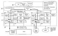
- FIG. 13is a diagram showing a configuration of a conventional network relaying apparatus.
- a router 100includes a routing manager (RM) 110 , router buses 120 , network interfaces (NIF) 130 and ports 140 . Each port 140 is connected to an appropriate network 150 .
- RMrouting manager
- NIFnetwork interfaces
- Each network interface 130receives a packet from a network connected to the port 140 , and transmits the received packet through the router bus 120 to the routing manager 110 .
- the routing manager 110includes a routing table for holding the routing information, and using this routing information, determines the network 150 of the destination from the address of the packet received, and transmits the packet to the network interface 130 of the port 140 connected to the network 150 .
- the network interface 130 that has received the packet from the routing manager 110sends out the packet to the destination network 150 .
- the routing manager 110updates and maintains the routing information held in the routing table based on the header information of the packet received, and has the function of overall management of the router 100 .
- the route searchuses a route search table (routing table) prepared from the component definition information and the information obtained by exchange between the routers.
- the routing tableis for searching the information (next hop information) as to the output port, the next hop address and whether the network is directly connected or not with a set of the network address and the network mask length as a key.
- JP-A-05-199230U.S. Pat. No. 5,434,863 discloses an internetwork system and a communication network system which can flexibly meet the size requirement of the network without adversely affecting the high-speed routing process.
- a router manager and a plurality of routing accelerator modulesare coupled to each other with a high-speed bus
- each routing acceleratoris connected with a plurality of independent communication ports.
- a plurality of the routing acceleratorsmakes possible a high-speed routing and by adding the routing accelerators, the requirement for increasing the network size can be easily met.
- the routerrequires the processing of the routing protocol (such as the Routing Information Protocol (RIP) or Open Shortest Path First (OSPF) included in TCP/IP protocol group) for exchanging information on the network between the routers.
- the processing of the network management protocolsuch as Simple Network Management Protocol (SNMP) which is one of the TCP/IP protocol group
- SNMPSimple Network Management Protocol
- the conventional routertherefore, cannot easily meet the requirement of the high-speed lines such as the high-speed LAN (Local Area Network), the wide-band ISDN (Integrated Services Digital Network) and ATM (Asynchronous Transfer Mode) that have recently found practical applications.
- the number of the ports and the communication traffic that can be supportedis limited. It is therefore difficult to expand the structure of the port menu or improve the performance of the router smoothly in accordance with the traffic and the number of ports.
- the data processing system used with the router and the bridgerequires an increased speed of the network controller reading transmission packets from a memory or writing the received packets into a memory.
- the conventional systemis required to limit the number of network controllers incorporated therein or requires, though low in cost effectiveness, the use of a high-speed memory or a dual port memory accessible from the processor or the network controller asynchronously.
- the routeris connected with a plurality of networks and relays the packets without connection. For this reason, packets may be concentrated in a router. Therefore, the prior art cannot secure the quality of service (QoS) such as the band control, the priority control or the discard control (for example, the band cannot be secured or packets cannot be transmitted within a specified time).
- QoSquality of service
- an object of the present inventionis to provide a network relaying apparatus and method capable of high-speed routing while assuring a high quality of service (QoS), high reliability and security.
- QoSquality of service
- Another object of the inventionis to provide a relaying apparatus and method of high applicability and high expandability which can meet the requirement for a variety of lines and sizes and is easy to improve the system performance.
- Still another object of the inventionis to provide a relaying apparatus and method in which the types of protocol that can be processed can be increased to facilitate the connection with the existing systems.
- Yet another object of the inventionis to execute high-speed operation of route search or the like by use of a high-speed memory as some of the parts into which the storage unit is divided.
- a further object of the inventionis to improve the packet processing capacity by suppressing the competition for access to the memory for storing packets without using any unnecessarily high-speed memory or a dual-port memory.
- a network relaying apparatusconnecting a plurality of networks for transferring packets input from the networks to the next destination based on the route information, comprising:
- At least a network interfaceconnected to the networks for controlling the interface with the networks
- At least a routing processorhaving a packet buffer and a header memory readable and writable at high speed and connected with one or a plurality of network interfaces for routing the packets input from the network interfaces;
- a connectorfor connecting the routing manager and a plurality of the routing processors respectively;
- the first network interfaceoutputs the packets input from the networks to the first routing processor connected with the first network interface
- the first routing processorstores the input packets in a packet buffer and the header information on the input packets in a header memory
- header memoryis accessed to search for the destination of the input packets stored in the packet buffer based on the stored header information
- the connectortransmits the output packet from the first routing processor to a second routing processor of the searched destination.
- a network relaying method for a network relaying apparatuscomprising a network interface connected to the networks, a routing processor for routing the packets input from the network interfaces, a routing manager for managing the internal parts of the system, a connector for connecting a plurality of the routing processors, and means for outputting the packets input from the networks to the destination, comprising the steps of;
- the first routing processorto store the input packets in a packet buffer and the header information on the input packet in a high-speed readable and writable header memory independent of the packet buffer;
- the first routing processorto access the header memory and search for a destination of the input packet stored in the packet buffer based on the stored header information
- FIG. 1is a diagram showing a configuration of a network relaying apparatus according to the present invention.
- FIG. 2is a diagram showing an internal structure of a routing processor for explaining the operation of a network relaying apparatus.
- FIG. 3is a sequence diagram showing an outline of the operation of the network relaying apparatus.
- FIGS. 4A-4Bare diagrams for explaining a packet buffer and a header RAM (Random Access Memory).
- FIGS. 5A-5Care diagrams for explaining each table used for route search.
- FIG. 6is a diagram for explaining the high-speed processing in the routing processor.
- FIG. 7is a diagram showing a configuration of a search engine in hardware.
- FIG. 8is a diagram for explaining the high-speed processing by pipelining control.
- FIG. 9is a diagram for explaining the flow search processing.
- FIG. 10is a diagram for explaining a flow search table.
- FIG. 11is a diagram for explaining a first input line limiting system.
- FIG. 12is a diagram for explaining a second input line limiting system.
- FIG. 13is a diagram showing a configuration of a conventional network relaying apparatus.
- FIG. 1is a diagram showing a configuration of a network relaying apparatus according to this invention.
- a router 1includes a plurality of routing processors (RP) 10 , a crossbar switch (CS) 20 , at least a network interface (NIF) 30 , at least a port 40 , a routing manager (RM) 60 and a power supply (PS) 70 .
- Each port 40is connected to an appropriate network.
- the network 50is a LAN, a WAN (Wide Area Network) or an ATM, for example.
- the power supply 70 or each common partcan be doubled as required.
- the routing manager functionis divided into the routing processors 10 for executing the routing function and the routing manager 60 for managing the router 1 .
- the router 1includes a plurality of routing processors 10 each having one or a plurality of network interfaces 30 .
- the routing manager 60has the function of overall management of the router 1 and at the same time executes the route calculation function. Further, the routing manager 60 exchanges the routing information with other routers and distributes the routing information to each routing processor 10 within each router.
- the routing manager 60has a dual structure.
- the switch 20has a crossbar switch or the like for communication and exchange between the routing processors 10 or between a routing processor 10 and the routing manager 60 .
- the switch 20is also formed in dual structure in the case under consideration.
- the switch 20may be replaced with a bus or the like for connection. Also, in the case where the crossbar switch is used, the connection route is not occupied by the routing manager 60 and one of the routing processors 10 but can be shared by a plurality of the routing processors 10 at the same time.
- Each routing processor 10transfers packets through the network interface 30 connected thereto.
- a given routing processor 10can also transfer a packet to the network 50 connected to another routing processor 10 through the switch 20 .
- the routing processors 10have each function thereof designed to perform a high-speed operation. More specifically, the routing processors 10 have such functions as switching, route search, forwarding, filtering, offering QoS and IP (Internet Protocol) multicasting.
- Each routing processor 10has an appropriate input buffer and an output buffer for each port 40 of the network interface 30 within it or for each of the other routing processors 10 and the routing manager 60 .
- Each network interface 30has one or a plurality of ports 40 for controlling the interface between the networks 50 and the routing processors 10 .
- FIG. 2is a diagram showing the internal structure of the routing processor for explaining the operation of the network relaying apparatus. With reference to this diagram showing the internal structure of the routing processor 10 , an explanation will be given of the operation of searching the route and transferring packets to the destination determined as the result of the route search.
- the routing processors 10each includes a transfer engine 13 , a search engine 14 , a header RAM 11 , a packet buffer 12 , a route table 15 , an ARP (address resolution protocol) table 16 , and a filter/QoS (flow search table) 17 .
- the transfer engine 13performs the packet input/output processing, for example.
- the search engine 14mainly performs the route search and the flow search such as the QoS control based on the header information of the packet.
- the search engine 14is configured with an exclusive LSI (Large Scale Integrated Circuit) or the like hardware capable of high-speed processing.
- the packet buffer 12has the packet stored therein until the transfer engine 13 transfers the input packet to the routing processor 10 .
- the header RAM 11extracts and stores only the header of the input packet.
- the header RAM 11is configured of a memory having a high read/write speed.
- This embodimentin addition to the buffer memory for storing the packets received from the network or transferred from other data processing systems, comprises a header RAM 11 accessible asynchronously with the packet buffer 12 .
- the packetis stored in the packet buffer 12 while storing (copying) the header of the packet in the RAM 11 at the same time.
- Each processor of the transfer engine 13 and the search engine 14fetches the header of the packet by use of the header RAM 11 , and while analyzing the header, the operation of reading/writing of the packet from or into the packet buffer 12 becomes possible. In this way, the header analysis of a packet and the transfer of other packets can be concurrently performed.
- the packet buffer 12is not used by the processor. Therefore, the transfer engine becomes accessible to the packet buffer 12 for transmission or transfer thereby avoiding the competition for access to the packet buffer 12 between the search engine 14 and the transfer engine 13 .
- the area for storing the packets received from the network and the header thereofcan be configured separately from the area for storing the packets transferred from the switch 20 and the header thereof. This isolated configuration facilitates the packet control.
- the route table 15 , the ARP table 16 and the filter/QoS tableare configured independently of each other.
- the search engine 14can access the tables individually for read or write operation, thereby making it possible to search for the routing information and the QoS at high speed. Further, in order to realize the high-speed routing, the pipelining process can be carried out. Each table and the pipelining process will be described in detail later.
- FIG. 3is a sequence diagram showing an outline of the operation of a network relaying apparatus.
- the first network interface 30transmits it to the transfer engine 13 .
- the transfer engine 13stores the received packet in the packet buffer 12 (S 301 ). Also, the transfer engine 13 extracts only the header of the input packet and by adding the internal header, forms header information, which is stored in the header RAM 11 (S 301 ). The internal header will be described later.
- the search engine 14reads the header information by accessing the header RAM 11 .
- the transfer engine 13may transfer the header information stored in the header RAM 11 to the search engine 14 .
- the search engine 14the number or address of the router, the RP and the port of the destination, the information on the next transfer route such as a MAC (media access control) address and the information for controlling the communication quality such as the QoS control information are searched for appropriately in accordance with the header information (S 303 ).
- the search engine 14writes the destination information including the number or address searched and the transfer control information including the action information such as the QoS information in the header RAM 11 .
- the search engine 14may alternatively transmit the transfer control information to the transfer engine 13 .
- an output packetis produced (S 305 ) based on the packet stored in the packet buffer 12 and the header information (including the transfer control information) stored in the header RAM 11 .
- the transfer engine 13outputs the output packet thus produced to the destination.
- the transfer engine 13sets the packet in queue for the buffer of the particular other routing processor 10
- the transfer engine 13sets the packet in queue for the corresponding port 40 .
- the transfer route searched by the routing processor 10is not necessarily single, but the packets can be cast to a plurality of routes at a time. In such a case, the packets can be set in queue for an appropriate buffer of each of the plurality of the routes.
- FIG. 4is a diagram for explaining the packet buffer 12 and the header RAM 11 .
- FIG. 4Ashows an example of the format of the packet stored in the packet buffer 12 .
- the packet buffer 12is supplied with packets from the network 50 or the switch 20 .
- the packet formatis that of an IP packet, for example, to which a layer- 2 MAC header 401 is added.
- the IP packetincludes, for example, a layer- 3 IP header 402 , a layer- 4 header 403 and a payload 404 .
- the layer- 2 MAC header 401includes a source MAC address (SAMAC) constituting the physical address (hardware address) of the router which has sent the packet immediately before and a destination MAC address (DAMAC) constituting the physical address of the next router to receive the packet.
- the layer- 3 IP header 402includes a source ID address (hereinafter referred to as the SIP) constituting a source address (address of the transmission terminal) and a destination ID address (hereinafter referred to as the DIP) constituting a destination address (address of the receiving terminal).
- the layer- 4 header 403includes a source port (hereinafter referred to as the SPORT) indicating a protocol (upper-level application) and a destination port (hereinafter referred to as the DPORT).
- the payload 404includes the user data.
- each headermay store the TOS (type of service) indicating the order of priority and the information such as the protocol in the upper-level of the IP protocol. These information can be processed in the same manner as
- FIG. 4Bshows an example format of the header information stored in the header RAM.
- the header informationis configured with, for example, the layer- 2 MAC header 401 and the layer- 3 IP header 402 in the packet format to which the internal header 405 is added as the control information.
- the internal header 405includes the input line number, the output line number and the QoS control information.
- the internal packet format in the routeris configured with the packet format of the network to which the internal header 405 is added.
- the internal packetcan be formed of the information stored in the packet buffer 12 and the information stored in the header RAM 11 .
- the internal packetmay be transferred from the information of the packet buffer 12 alone by storing the internal packet format including the internal header 405 in the packet buffer 12 .
- the transfer control informationsuch as the destination information and the action information searched by the search engine 14 can be written in the internal header 405 .
- FIG. 5is a diagram for explaining each table used for route search.
- the entries in the route table 15include, for example, the destination IP address 501 , the IP address 502 of the next router, the local router transmission RP number 503 and the transmission port number 504 .
- the entries in the ARP table 16include the IP address 502 of the next router and the MAC address 506 of the next router.
- the entries of the filter/QoS table 17include, for example, the value (range) 507 of the IP header/layer- 4 header and the action 508 .
- the action 508includes the filtering process for passing or discarding a packet, the tunneling process for encapsulating or not encapsulating a packet and QoS. Especially, QoS will be explained later again.
- FIG. 6is a diagram for explaining the high-speed processing of the routing processor. With reference to this diagram, a method of realizing the packet transfer capable of following a high line speed on the order of gigabits. The high speed is realized by parallel processing or pipelining of the routing. Now, the operation will be explained with reference to the format shown in FIGS. 4 and 5.
- the routing processis divided roughly into the receiving process ⁇ circle around (1) ⁇ , the input search process ⁇ circle around (2) ⁇ , the output search process ⁇ circle around (3) ⁇ and the transmission process ⁇ circle around (4) ⁇ .
- the transfer engine 13receives a packet from the network interface 30 .
- the packet buffer 12has stored therein an input packet or a packet of the internal packet format with the internal header added thereto.
- the internal header 405is added to the layer- 2 MAC header 401 and the layer- 3 IP header 402 of the input packet to form the header information, which is stored in the RAM 11 .
- the header RAM 11can be read from and written into at high speed independently of the packet buffer 12 , and by storing only the header information therein, the storage capacity can be reduced for further increasing the processing rate.
- the search engine 14can access the extracted header information at appropriate timing.
- the search engine 14extracts the destination IP address in the layer- 3 IP header 402 from the header information, and based on this address, refers to the route table 15 to search for the IP address 502 of the next router, the transmission RP number 503 of the local router and the transmission port number 504 . Further, the search engine 14 , based on the reference information of the layer- 3 IP header 402 and the layer- 4 header 403 , searches the various items of the action 50 such as QoS on the input side from the received header information with reference to the filter/QoS table 17 . These input-side filter/QoS search and route search are can be executed concurrently since the tables are independently prepared.
- the search engine 14extracts the IP address of the next router determined in the input search process ⁇ circle around (2) ⁇ , and based on this address, searches for the MAC address 506 of the next router with reference to the ARP table 16 , while at the same time searching for various items of the action 508 on the output side such as QoS with reference to the filter/QoS table 17 .
- the output filter/QoS search and the line table/ARP searchcan be concurrently executed since each table is prepared independently.
- the transfer control information including the destination information such as the number/address information of the next destination determined and the action information such as the QoS control informationare stored in the header RAM 11 . These information can be written, for example, in the internal header 405 or at another appropriate position in the header information.
- the header information including the transfer control information searched in the output search process ⁇ circle around (3) ⁇is read from the header RAM 11 , and based on the header information and the packet buffer 12 , an output packet is produced and set in queue for the buffer of the network interface 30 , another routing processor 10 or the routing manager 60 .
- FIG. 7shows an example of the configuration of a search engine in hardware.
- the search engine 14can search the tables including the route table 15 , the ARP table 16 and the filter/QoS table 17 for the required data by a tree structure, for example.
- the route search processorfor searching for a destination route using the route table 15 as an example of the processor of the search engine 14 configured in hardware.
- the route search processor 213includes a tree structured search circuit 2130 , a read address generating circuit 2131 and a route search processing control circuit 2132 .
- the tree structured search circuit 2130searches the tree structure of n branches (where n is a power of 2) stored in each table such as the route table 15 to generate the pointer of the node next to be read, extract the check bit of the destination IP address of the received packet, determine the end of the tree structure search and update the candidate for the route information resulting from the search.
- the read address generating circuit 2131generates the memory address of a part of the words of the node actually read, in accordance with the check bit value and the pointer to the node to be read output from the tree structure search circuit 2130 .
- the route search processing control circuit 2132controls the route search processor 213 as a whole (the operation timing and the operating condition of each circuit).
- the tree structure search circuit 2130receives the destination IP address of the received packet from the header RAM 11 , and based on this destination IP address and the node mask length, generates the pointer to the next node and delivers it to the read address generating circuit 2131 . Also, the tree structured search circuit 2130 extracts the value of the check bit position (check bit value) of the destination IP address indicated by the node mask length and delivers it to the read address generating circuit 2131 .
- the read address generating circuit 2131generates a memory address where the node data to be read is stored, using the pointer to the node, the check bit value and the timing signal from the route search processing control circuit 2132 , and transmits it to the memory control circuit 2132 .
- the memory control circuit 2132generates a memory control signal using the memory address and the timing signal from the route search processing control circuit 2132 and transfers it to the route table 15 .
- the route table 15 that has received this memory control signaltransfers a corresponding node data to the tree structured search circuit 2130 using the signal line 215 .
- the tree structured search circuit 2130makes a search using this node data and in the case where it is determined to end the tree structured search, outputs a tree structured search end signal to the route search processing control circuit 2132 .
- the route search processing control circuit 2132checks a flag with entry in the route information held in the tree structured search circuit 2130 , and in the case where the value of the flag is 0, ends the route search process and notifies the transfer engine 13 of the absence of the search result. In the case where the value of the flag with entry is 1, on the other hand, the route information is output to end the search process and the next packet processing is controlled.
- FIG. 8is a diagram for explaining the high-speed processing by the pipelining control.
- the receiving process ⁇ circle around (1) ⁇ , the input search ⁇ circle around (2) ⁇ , the output search process ⁇ circle around (3) ⁇ and the transfer process ⁇ circle around (4) ⁇are carried out by pipelining and thus controlled so that each processor is in constant operation for increasing the speed of the routing process.
- the input filter process (input filter/QoS search) and the route table search (route search)are executed in parallel in the input search ⁇ circle around (2) ⁇ .
- the output search process ⁇ circle around (3) ⁇ , the output filter process (output filter/QoS search) and the output line table search (output line table/ARP search)are executed in parallel.
- the pipeliningis not limited to the structure shown in FIG. 8 but can be implemented in an appropriate sequence.
- the processor 1upon completion of the first process of the entry N by the processor 1 of all the processors described above, the processor 1 starts the process on the entry N+1 regardless of whether the second process of the entry is completed by the processor 2 for executing the second process subsequent to the first process.
- This pipelining processcan handle N entries in one procession session and therefore the processing speed is quadrupled.
- the flow searchis processed by pipelining divided into four processes. If the process is divided into P processes for pipelining, on the other hand, the performance will be improved by a factor of P.
- FIG. 9is a diagram for explaining the flow search process.
- a network relaying apparatussuch as a router lacks a preset connection, and therefore has no connection information unlike in the ATM switch nor QoS control information in the connection information table (packet type communication).
- the flow search means for searching the QoS control information with the information in the headeris required for each input packet in addition to the priority transfer function like the ATM switch.
- the priority transfer functionis applied to the searched QoS control information by the flow search means.
- the conditions for identifying the packets produced by combining such information as the internal information of the headerare called the flow conditions, a series of traffic coincident with the flow conditions is called the flow, and to determine whether the input packet meets the flow conditions and to detect the QoS control information and the action information such as transferability information is called the flow search.
- the QoS controlis inserted in the routing processor 10 - 1 on input side and the routing processor 10 - 2 on output side, and also the QoS function is provided to the switch 20 .
- the routing processor 10 - 1 on input sidehas an input search flow including a filter flow search 911 , a tunnel flow search 912 and a QoS flow search 913 .
- the routing processor 10 - 2 on output sidehas an output search flow including a filter flow search 921 , a tunnel flow search 922 and a QoS flow search 923 .
- the switch 20has the arbitration function for selecting the order of transmission according to the priority thus providing the QoS function.
- the switch 20like the routing processors 10 - 1 and 10 - 2 , can be provided with the filter flow search, the tunnel flow search and the QoS flow search.
- the filter flow search 911 , 921determines whether the packet is passed or discarded.
- the tunnel flow search 912 , 922determines whether the packet is encapsulated or not, and in the case where it is encapsulated, executes the encapsulation software.
- the QoS flow search 913 , 923includes the packet priority control, the packet discard control and the band control, for example.
- the priority controlis the one for transmitting the data of high importance degree or data of the real time system in priority.
- the discard controlis the one for discarding the data of low importance degree in the case of heavy traffic or a fault for preventing the loss of important data.
- the band controlis for segmenting a line into a plurality of bands or changing the bandwidth. For example, the priority control and discard control can be accomplished by controlling the traffic using the matrix of priority class and discard class.
- the HNA/SNAHaitachi network architecture/Systems network architecture
- voice and animationcan be controlled to small delay
- FTPfile transfer protocol
- mail and WWWWorld Wide Web
- a small discard ratecan be set for the control packets and a large discard rate for the voice and animation.
- the packet sent from the routing processors 10contains the QoS control information in the control information.
- the switch 20especially on output side, carries out the priority control using the QoS control information. Actually, however, this can be accomplished by the output control by setting in queue in the order of priority. As a result, the communication and transfer of an even higher quality is made possible.
- FIG. 10is a diagram for explaining the flow search table.
- a reference field 101includes the source IP address, the destination IP address, the packet length, the IP priority, the IP host protocol, the arrival check flag, the transfer destination TCP/UDP port and the final destination TCP/UDP (Transmission Control Protocol/User Datagram Protocol) port.
- An action field 102stores therein a filter (pass/discard), a tunnel (encapsulate/not encapsulate) and QoS (delay class, discard class, band, etc.).
- QoS flow searchTake the QoS flow search as an example. A similar method can be employed also for the filter flow search or the tunnel flow search.
- the control information of the respective flowscan be stored in mixture in the action field 102 , or a flow search table can be prepared for each flow.
- the linear search methodwhen determining the QoS control information as one action, the preset entries are read sequentially top down from the entry table, and then it is determined whether the values of the header of the packet are all coincident with the valid flow conditions in the reference field 101 . In the case of coincidence, the QoS control information in the action field 102 in the entry is determined as the packet QoS control information and the QoS flow search is ended. Once the coincidence with the flow conditions is searched for successfully, the QoS control information in the action field 102 is determined as the QoS control information so that the flow search is ended without executing the next entry search.
- the flow search method according to this embodimentdesirably employs an input line limiting method or the like in which the flow search can be carried out more rapidly than in the linear search method even in the case where a large amount of entries are set.
- the input line limiting methodwill be explained briefly below. In the input line limiting method, only the entries coincident with the input line number making up the reference field of the linear search method are searched to assure high speed.
- FIG. 11is a diagram for explaining a first input line limiting method.
- the first input line limiting methodan entry 511 - i with the input line number and the input line number valid bit deleted from the reference field of the linear search method is set for each input line.
- the flow condition unit 521 - iincludes the SIP upper limit 501 , the SIP lower limit 502 , the DIP upper limit 503 and the DIP lower limit 504 indicating the condition for identifying the source or destination user, an IP validity bit 562 indicating the validity of the upper limits and the lower limits of SIP and DIP, the SPORT 505 providing a source port, the DPORT 506 providing a destination port, and a port validity bit 563 indicating the validity of the SPORT 505 and the DPORT 506 .
- the QoS control information unit 530 -iincludes, for example, the QoS control information 507 used for the priority transfer function.
- FIG. 12is a diagram for explaining a second input line limiting method.
- the lists 540 constituting the addresses in the entry table 750is set in the list table 760 for each input line.
- the list 540 - 11 having the list table address “1”is the address of the entry 511 - 1
- the list 540 - 12 having the list table address “2”is the address of the entry 511 -H.
- the list 540 assigned to the input line supplied with a packetis read, and the entry 511 - i pointed to by this list 540 is read out.
- the memory for implementing an entry tablecan be effectively used if a list 540 having a small bit width (for example, about 10 bits for as many as 1024 entries) is held for each input line and an entry 511 - i having a large bit width is shared by the input lines. As a result, a multiplicity of entries 511 - i can be set while realizing a high speed operation at the same time.
- a small bit widthfor example, about 10 bits for as many as 1024 entries
- Another example of the flow detection methodis the output line limiting method.
- the output line limiting methodonly the entry 511 - i for which the output line number providing the flow condition is coincident is processed in the same manner as in the input line limiting method described above for realizing a high-speed flow detection.
- a SAMAC limiting methodis available which uses SAMAC instead of the input line number in the header information as the flow condition.
- the SAMAC limiting methodthe SAMAC group is defined and the entry is limited by the SAMAC identifier providing a SAMAC group identifier, so that the flow search similar to the input line limiting method can be executed.
- a network relaying apparatus and method for routing packets at high speed while assuring a high communication quality (QoS), a high reliability and securityis provided.
- QoScommunication quality
- the high applicability and expandabilitycan meet the requirement for a multiplicity of lines and a great variety of sizes on the one hand and facilitates the improvement of the system performance on the other.
- the present inventionfacilitates the connection with the existing systems by increasing the types of protocols that can be processed.
- the search including the route searchcan be carried out at high speed by segmenting the storage unit and using a part thereof as a high-speed memory.
- the competition for access to the memory storing the packetscan be suppressed and thus the packet processing capacity can be improved without limiting the number of the network controllers that can be incorporated in the system or without using a high-speed memory unit or a dual-port memory unit.
- the processor of the search enginereads the header information from the header RAM, the packet buffer is not used by the processor. Therefore, the transfer engine can access the packet buffer for packet transmission or transfer, thereby preventing the competition for access to the packet buffer between the search engine and the transfer engine.
Landscapes
- Engineering & Computer Science (AREA)
- Computer Networks & Wireless Communication (AREA)
- Signal Processing (AREA)
- Quality & Reliability (AREA)
- Data Exchanges In Wide-Area Networks (AREA)
Abstract
Description
Claims (10)
Priority Applications (1)
| Application Number | Priority Date | Filing Date | Title |
|---|---|---|---|
| US09/511,798US6683885B1 (en) | 1999-02-24 | 2000-02-23 | Network relaying apparatus and network relaying method |
Applications Claiming Priority (4)
| Application Number | Priority Date | Filing Date | Title |
|---|---|---|---|
| JP11-045959 | 1999-02-24 | ||
| JP4595999AJP3645733B2 (en) | 1999-02-24 | 1999-02-24 | Network relay device and network relay method |
| US09/266,635US6560233B1 (en) | 1998-03-12 | 1999-03-11 | Data processing apparatus and network relaying apparatus |
| US09/511,798US6683885B1 (en) | 1999-02-24 | 2000-02-23 | Network relaying apparatus and network relaying method |
Related Parent Applications (1)
| Application Number | Title | Priority Date | Filing Date |
|---|---|---|---|
| US09/266,635Continuation-In-PartUS6560233B1 (en) | 1998-03-12 | 1999-03-11 | Data processing apparatus and network relaying apparatus |
Publications (1)
| Publication Number | Publication Date |
|---|---|
| US6683885B1true US6683885B1 (en) | 2004-01-27 |
Family
ID=30117237
Family Applications (1)
| Application Number | Title | Priority Date | Filing Date |
|---|---|---|---|
| US09/511,798Expired - LifetimeUS6683885B1 (en) | 1999-02-24 | 2000-02-23 | Network relaying apparatus and network relaying method |
Country Status (1)
| Country | Link |
|---|---|
| US (1) | US6683885B1 (en) |
Cited By (36)
| Publication number | Priority date | Publication date | Assignee | Title |
|---|---|---|---|---|
| US20020073216A1 (en)* | 2000-12-08 | 2002-06-13 | Gaur Daniel R. | Method and apparatus for improving transmission performance by caching frequently-used packet headers |
| US20020080755A1 (en)* | 2000-12-22 | 2002-06-27 | Tasman Mitchell Paul | Architecture and mechanism for forwarding layer interfacing for networks |
| US20020124086A1 (en)* | 2000-11-24 | 2002-09-05 | Mar Aaron S. | Policy change characterization method and apparatus |
| US20020129025A1 (en)* | 2001-03-07 | 2002-09-12 | Broadcom Corporation | System and method for slot based ARL table learning and concurrent table search using range address insertion blocking |
| US20020176414A1 (en)* | 2001-05-28 | 2002-11-28 | Hitachi, Ltd. | Packet switching apparatus |
| US20030040898A1 (en)* | 2001-08-17 | 2003-02-27 | Mcwilliams Thomas M. | Method and apparatus for simulation processor |
| US20030191857A1 (en)* | 2001-10-18 | 2003-10-09 | Terrell William C. | Router and methods using in-band link between managing processor and routing processor |
| US20040028033A1 (en)* | 2000-09-14 | 2004-02-12 | Tommi Koistinen | Sharing of protocol processing |
| US20040085973A1 (en)* | 2002-10-31 | 2004-05-06 | Toru Tanada | Communication apparatus and network interfacing device |
| US20040125757A1 (en)* | 2002-12-30 | 2004-07-01 | Martti Mela | Streaming media |
| US20050041676A1 (en)* | 2003-08-08 | 2005-02-24 | Bbnt Solutions Llc | Systems and methods for forming an adjacency graph for exchanging network routing data |
| US20050050221A1 (en)* | 2003-08-27 | 2005-03-03 | Tasman Mitchell Paul | Systems and methods for forwarding data units in a communications network |
| US20050232285A1 (en)* | 2001-10-18 | 2005-10-20 | Terrell William C | System and method of providing network node services |
| US6981058B2 (en)* | 2001-03-07 | 2005-12-27 | Broadcom Corporation | System and method for slot based ARL table learning with concurrent table search using write snoop |
| US20060109852A1 (en)* | 2004-11-19 | 2006-05-25 | Massoud Hadjiahmad | Auto configuration for asynchronous transfer mode based access device |
| US20060109851A1 (en)* | 2004-11-19 | 2006-05-25 | Massoud Hadjiahmad | Auto configuration for asynchronous transfer mode based access device |
| US20070047453A1 (en)* | 2005-08-24 | 2007-03-01 | International Business Machines Corporation | Reliable message transfer over an unreliable network |
| US20080008202A1 (en)* | 2002-10-31 | 2008-01-10 | Terrell William C | Router with routing processors and methods for virtualization |
| US20080028077A1 (en)* | 2006-07-27 | 2008-01-31 | Masanori Kamata | Packet forwarding control method and packet forwarding apparatus |
| US20080037542A1 (en)* | 2001-04-16 | 2008-02-14 | Franck Le | Method and apparatus for classifying ip data |
| US7369512B1 (en) | 2003-11-06 | 2008-05-06 | Bbn Technologies Corp. | Systems and methods for efficient packet distribution in an ad hoc network |
| US20100009758A1 (en)* | 2007-10-17 | 2010-01-14 | Dispersive Networks Inc. | Multiplexed Client Server (MCS) Communications and Systems |
| US7668083B1 (en) | 2003-10-28 | 2010-02-23 | Bbn Technologies Corp. | Systems and methods for forwarding data in a communications network |
| US20100158023A1 (en)* | 2008-12-23 | 2010-06-24 | Suvhasis Mukhopadhyay | System-On-a-Chip and Multi-Chip Systems Supporting Advanced Telecommunication Functions |
| US20100161938A1 (en)* | 2008-12-23 | 2010-06-24 | Marco Heddes | System-On-A-Chip Supporting A Networked Array Of Configurable Symmetric Multiprocessing Nodes |
| US20100162265A1 (en)* | 2008-12-23 | 2010-06-24 | Marco Heddes | System-On-A-Chip Employing A Network Of Nodes That Utilize Logical Channels And Logical Mux Channels For Communicating Messages Therebetween |
| US20100158005A1 (en)* | 2008-12-23 | 2010-06-24 | Suvhasis Mukhopadhyay | System-On-a-Chip and Multi-Chip Systems Supporting Advanced Telecommunication Functions |
| US20100191911A1 (en)* | 2008-12-23 | 2010-07-29 | Marco Heddes | System-On-A-Chip Having an Array of Programmable Processing Elements Linked By an On-Chip Network with Distributed On-Chip Shared Memory and External Shared Memory |
| US20100254309A1 (en)* | 2009-04-07 | 2010-10-07 | Bbn Technologies Corp. | System, device, and method for unifying differently-routed networks using virtual topology representations |
| US7983239B1 (en) | 2003-01-07 | 2011-07-19 | Raytheon Bbn Technologies Corp. | Systems and methods for constructing a virtual model of a multi-hop, multi-access network |
| US20120047349A1 (en)* | 2010-08-23 | 2012-02-23 | Nec Corporation | Data transfer system |
| US20130077636A1 (en)* | 2011-09-23 | 2013-03-28 | Alcatel-Lucent Usa Inc. | Time-Preserved Transmissions In Asynchronous Virtual Machine Replication |
| US8955110B1 (en) | 2011-01-14 | 2015-02-10 | Robert W. Twitchell, Jr. | IP jamming systems utilizing virtual dispersive networking |
| US9071607B2 (en) | 2007-10-17 | 2015-06-30 | Dispersive Networks Inc. | Virtual dispersive networking systems and methods |
| US20210089477A1 (en)* | 2019-09-19 | 2021-03-25 | Samsung Electronics Co., Ltd. | Systems and methods for message tunneling |
| US20230393996A1 (en)* | 2019-09-19 | 2023-12-07 | Samsung Electronics Co., Ltd. | Systems and methods for message tunneling |
Citations (8)
| Publication number | Priority date | Publication date | Assignee | Title |
|---|---|---|---|---|
| US4692917A (en)* | 1984-11-27 | 1987-09-08 | Kokusai Denshin Denwa Co., Ltd. | Packet switching system |
| US5434863A (en) | 1991-08-30 | 1995-07-18 | Hitachi, Ltd. | Internetworking apparatus for connecting plural network systems and communication network system composed of plural network systems mutually connected |
| US5764895A (en)* | 1995-01-11 | 1998-06-09 | Sony Corporation | Method and apparatus for directing data packets in a local area network device having a plurality of ports interconnected by a high-speed communication bus |
| US5838677A (en)* | 1995-04-18 | 1998-11-17 | Hitachi, Ltd. | Switching system having means for congestion control by monitoring packets in a shared buffer and by suppressing the reading of packets from input buffers |
| US5884040A (en)* | 1995-01-11 | 1999-03-16 | Sony Corporation | Per-packet jamming in a multi-port bridge for a local area network |
| US5920566A (en)* | 1997-06-30 | 1999-07-06 | Sun Microsystems, Inc. | Routing in a multi-layer distributed network element |
| US6032190A (en)* | 1997-10-03 | 2000-02-29 | Ascend Communications, Inc. | System and method for processing data packets |
| US6259699B1 (en)* | 1997-12-30 | 2001-07-10 | Nexabit Networks, Llc | System architecture for and method of processing packets and/or cells in a common switch |
- 2000
- 2000-02-23USUS09/511,798patent/US6683885B1/ennot_activeExpired - Lifetime
Patent Citations (8)
| Publication number | Priority date | Publication date | Assignee | Title |
|---|---|---|---|---|
| US4692917A (en)* | 1984-11-27 | 1987-09-08 | Kokusai Denshin Denwa Co., Ltd. | Packet switching system |
| US5434863A (en) | 1991-08-30 | 1995-07-18 | Hitachi, Ltd. | Internetworking apparatus for connecting plural network systems and communication network system composed of plural network systems mutually connected |
| US5764895A (en)* | 1995-01-11 | 1998-06-09 | Sony Corporation | Method and apparatus for directing data packets in a local area network device having a plurality of ports interconnected by a high-speed communication bus |
| US5884040A (en)* | 1995-01-11 | 1999-03-16 | Sony Corporation | Per-packet jamming in a multi-port bridge for a local area network |
| US5838677A (en)* | 1995-04-18 | 1998-11-17 | Hitachi, Ltd. | Switching system having means for congestion control by monitoring packets in a shared buffer and by suppressing the reading of packets from input buffers |
| US5920566A (en)* | 1997-06-30 | 1999-07-06 | Sun Microsystems, Inc. | Routing in a multi-layer distributed network element |
| US6032190A (en)* | 1997-10-03 | 2000-02-29 | Ascend Communications, Inc. | System and method for processing data packets |
| US6259699B1 (en)* | 1997-12-30 | 2001-07-10 | Nexabit Networks, Llc | System architecture for and method of processing packets and/or cells in a common switch |
Cited By (91)
| Publication number | Priority date | Publication date | Assignee | Title |
|---|---|---|---|---|
| US20040028033A1 (en)* | 2000-09-14 | 2004-02-12 | Tommi Koistinen | Sharing of protocol processing |
| US7636355B2 (en)* | 2000-09-14 | 2009-12-22 | Nokia Corporation | Sharing of protocol processing |
| US20020124086A1 (en)* | 2000-11-24 | 2002-09-05 | Mar Aaron S. | Policy change characterization method and apparatus |
| US6980555B2 (en)* | 2000-11-24 | 2005-12-27 | Redback Networks Inc. | Policy change characterization method and apparatus |
| US7032035B2 (en)* | 2000-12-08 | 2006-04-18 | Intel Corporation | Method and apparatus for improving transmission performance by caching frequently-used packet headers |
| US20020073216A1 (en)* | 2000-12-08 | 2002-06-13 | Gaur Daniel R. | Method and apparatus for improving transmission performance by caching frequently-used packet headers |
| US7116640B2 (en) | 2000-12-22 | 2006-10-03 | Mitchell Paul Tasman | Architecture and mechanism for forwarding layer interfacing for networks |
| US20020080755A1 (en)* | 2000-12-22 | 2002-06-27 | Tasman Mitchell Paul | Architecture and mechanism for forwarding layer interfacing for networks |
| US6965945B2 (en)* | 2001-03-07 | 2005-11-15 | Broadcom Corporation | System and method for slot based ARL table learning and concurrent table search using range address insertion blocking |
| US20020129025A1 (en)* | 2001-03-07 | 2002-09-12 | Broadcom Corporation | System and method for slot based ARL table learning and concurrent table search using range address insertion blocking |
| US6981058B2 (en)* | 2001-03-07 | 2005-12-27 | Broadcom Corporation | System and method for slot based ARL table learning with concurrent table search using write snoop |
| US7974266B2 (en)* | 2001-04-16 | 2011-07-05 | Spyder Navigations L.L.C. | Method and apparatus for classifying IP data |
| US20080037542A1 (en)* | 2001-04-16 | 2008-02-14 | Franck Le | Method and apparatus for classifying ip data |
| US7173932B2 (en)* | 2001-05-28 | 2007-02-06 | Hitachi, Ltd. | Packet switching apparatus |
| US20070110060A1 (en)* | 2001-05-28 | 2007-05-17 | Hitachi, Ltd. | Packet switching apparatus |
| US8077719B2 (en) | 2001-05-28 | 2011-12-13 | Hitachi, Ltd. | Packet switching apparatus |
| US20020176414A1 (en)* | 2001-05-28 | 2002-11-28 | Hitachi, Ltd. | Packet switching apparatus |
| US7043596B2 (en)* | 2001-08-17 | 2006-05-09 | Sun Microsystems, Inc. | Method and apparatus for simulation processor |
| US20030040898A1 (en)* | 2001-08-17 | 2003-02-27 | Mcwilliams Thomas M. | Method and apparatus for simulation processor |
| US20050232285A1 (en)* | 2001-10-18 | 2005-10-20 | Terrell William C | System and method of providing network node services |
| US7447197B2 (en) | 2001-10-18 | 2008-11-04 | Qlogic, Corporation | System and method of providing network node services |
| US20030210686A1 (en)* | 2001-10-18 | 2003-11-13 | Troika Networds, Inc. | Router and methods using network addresses for virtualization |
| US20030189936A1 (en)* | 2001-10-18 | 2003-10-09 | Terrell William C. | Router with routing processors and methods for virtualization |
| US7362702B2 (en) | 2001-10-18 | 2008-04-22 | Qlogic, Corporation | Router with routing processors and methods for virtualization |
| US7200144B2 (en) | 2001-10-18 | 2007-04-03 | Qlogic, Corp. | Router and methods using network addresses for virtualization |
| US20030191857A1 (en)* | 2001-10-18 | 2003-10-09 | Terrell William C. | Router and methods using in-band link between managing processor and routing processor |
| US20070183421A1 (en)* | 2001-10-18 | 2007-08-09 | Terrell William C | Router and methods using network addresses for virtualization |
| US7292567B2 (en) | 2001-10-18 | 2007-11-06 | Qlogic Corporation | Router and methods for distributed virtualization |
| US20040085973A1 (en)* | 2002-10-31 | 2004-05-06 | Toru Tanada | Communication apparatus and network interfacing device |
| US20080008202A1 (en)* | 2002-10-31 | 2008-01-10 | Terrell William C | Router with routing processors and methods for virtualization |
| US9906573B2 (en) | 2002-12-30 | 2018-02-27 | Intellectual Ventures I Llc | Streaming media |
| US7724691B2 (en)* | 2002-12-30 | 2010-05-25 | Martti Mela | Streaming media |
| US20040125757A1 (en)* | 2002-12-30 | 2004-07-01 | Martti Mela | Streaming media |
| US8599835B2 (en) | 2002-12-30 | 2013-12-03 | Intellectual Ventures I Llc | Streaming media |
| US9231994B2 (en) | 2002-12-30 | 2016-01-05 | Intellectual Ventures I Llc | Streaming media |
| US20100138545A1 (en)* | 2002-12-30 | 2010-06-03 | Martti Mela | Streaming media |
| US7983239B1 (en) | 2003-01-07 | 2011-07-19 | Raytheon Bbn Technologies Corp. | Systems and methods for constructing a virtual model of a multi-hop, multi-access network |
| US7881229B2 (en) | 2003-08-08 | 2011-02-01 | Raytheon Bbn Technologies Corp. | Systems and methods for forming an adjacency graph for exchanging network routing data |
| US20050041676A1 (en)* | 2003-08-08 | 2005-02-24 | Bbnt Solutions Llc | Systems and methods for forming an adjacency graph for exchanging network routing data |
| US8103792B2 (en) | 2003-08-27 | 2012-01-24 | Raytheon Bbn Technologies Corp. | Systems and methods for forwarding data units in a communications network |
| US20050050221A1 (en)* | 2003-08-27 | 2005-03-03 | Tasman Mitchell Paul | Systems and methods for forwarding data units in a communications network |
| US7606927B2 (en)* | 2003-08-27 | 2009-10-20 | Bbn Technologies Corp | Systems and methods for forwarding data units in a communications network |
| US7668083B1 (en) | 2003-10-28 | 2010-02-23 | Bbn Technologies Corp. | Systems and methods for forwarding data in a communications network |
| US7369512B1 (en) | 2003-11-06 | 2008-05-06 | Bbn Technologies Corp. | Systems and methods for efficient packet distribution in an ad hoc network |
| US20060109852A1 (en)* | 2004-11-19 | 2006-05-25 | Massoud Hadjiahmad | Auto configuration for asynchronous transfer mode based access device |
| US7460490B2 (en) | 2004-11-19 | 2008-12-02 | Analog Devices, Inc. | Auto configuration for asynchronous transfer mode based access device |
| US20060109851A1 (en)* | 2004-11-19 | 2006-05-25 | Massoud Hadjiahmad | Auto configuration for asynchronous transfer mode based access device |
| US7406085B2 (en) | 2004-11-19 | 2008-07-29 | Analog Devices, Inc. | Auto configuration for asynchronous transfer mode based access device |
| US8018844B2 (en)* | 2005-08-24 | 2011-09-13 | International Business Machines Corporation | Reliable message transfer over an unreliable network |
| US20070047453A1 (en)* | 2005-08-24 | 2007-03-01 | International Business Machines Corporation | Reliable message transfer over an unreliable network |
| US20080028077A1 (en)* | 2006-07-27 | 2008-01-31 | Masanori Kamata | Packet forwarding control method and packet forwarding apparatus |
| US7792972B2 (en)* | 2006-07-27 | 2010-09-07 | Hitachi, Ltd. | Packet forwarding control method and packet forwarding apparatus |
| US8848704B2 (en)* | 2007-10-17 | 2014-09-30 | Dispersive Networks Inc. | Facilitating network routing using virtualization |
| US9350794B2 (en)* | 2007-10-17 | 2016-05-24 | Dispersive Networks, Inc. | Transmitting packet from device after timeout in network communications utilizing virtual network connection |
| US10469375B2 (en)* | 2007-10-17 | 2019-11-05 | Dispersive Networks, Inc. | Providing network communications using virtualization based on information appended to packet |
| US20100009758A1 (en)* | 2007-10-17 | 2010-01-14 | Dispersive Networks Inc. | Multiplexed Client Server (MCS) Communications and Systems |
| US20120014389A1 (en)* | 2007-10-17 | 2012-01-19 | Twitchell Robert W | Providing network communications satisfying application requirements using virtualization |
| US9634931B2 (en)* | 2007-10-17 | 2017-04-25 | Dispersive Networks, Inc. | Providing network communications using virtualization based on protocol information in packet |
| US20120020352A1 (en)* | 2007-10-17 | 2012-01-26 | Twitchell Robert W | Facilitating network routing using virtualization |
| US20120020353A1 (en)* | 2007-10-17 | 2012-01-26 | Twitchell Robert W | Transmitting packet from device after timeout in network communications utilizing virtual network connection |
| US20120026889A1 (en)* | 2007-10-17 | 2012-02-02 | Twitchell Jr Robert W | Providing network communications using virtualization based on protocol information in packet |
| US20160294687A1 (en)* | 2007-10-17 | 2016-10-06 | Dispersive Networks, Inc. | Transmitting packet from device after timeout in network communications utilizing virtual network connection |
| US9246980B2 (en) | 2007-10-17 | 2016-01-26 | Dispersive Networks Inc. | Validating packets in network communications |
| US9241026B2 (en) | 2007-10-17 | 2016-01-19 | Dispersive Networks Inc. | Facilitating network communications with control server and devices utilizing virtual network connections |
| US8539098B2 (en) | 2007-10-17 | 2013-09-17 | Dispersive Networks, Inc. | Multiplexed client server (MCS) communications and systems |
| US9241025B2 (en) | 2007-10-17 | 2016-01-19 | Dispersive Networks Inc. | Network communications of applications running on devices utilizing virtual network connections with asymmetrical network paths |
| US9167025B2 (en) | 2007-10-17 | 2015-10-20 | Dispersive Networks Inc. | Network communications of application running on device utilizing routing of data packets using virtual network connection |
| US9100405B2 (en) | 2007-10-17 | 2015-08-04 | Dispersive Networks Inc. | Apparatus, systems and methods utilizing dispersive networking |
| US9071607B2 (en) | 2007-10-17 | 2015-06-30 | Dispersive Networks Inc. | Virtual dispersive networking systems and methods |
| US8959627B2 (en) | 2007-10-17 | 2015-02-17 | Dispersive Networks, Inc. | Quarantining packets received at device in network communications utilizing virtual network connection |
| US9055042B2 (en)* | 2007-10-17 | 2015-06-09 | Dispersive Networks Inc. | Providing network communications satisfying application requirements using virtualization |
| US9059975B2 (en)* | 2007-10-17 | 2015-06-16 | Dispersive Networks Inc. | Providing network communications using virtualization based on protocol information in packet |
| US20100191814A1 (en)* | 2008-12-23 | 2010-07-29 | Marco Heddes | System-On-A-Chip Employing A Network Of Nodes That Utilize Receive Side Flow Control Over Channels For Messages Communicated Therebetween |
| US20100158005A1 (en)* | 2008-12-23 | 2010-06-24 | Suvhasis Mukhopadhyay | System-On-a-Chip and Multi-Chip Systems Supporting Advanced Telecommunication Functions |
| US20100191911A1 (en)* | 2008-12-23 | 2010-07-29 | Marco Heddes | System-On-A-Chip Having an Array of Programmable Processing Elements Linked By an On-Chip Network with Distributed On-Chip Shared Memory and External Shared Memory |
| US20100161938A1 (en)* | 2008-12-23 | 2010-06-24 | Marco Heddes | System-On-A-Chip Supporting A Networked Array Of Configurable Symmetric Multiprocessing Nodes |
| US20100158023A1 (en)* | 2008-12-23 | 2010-06-24 | Suvhasis Mukhopadhyay | System-On-a-Chip and Multi-Chip Systems Supporting Advanced Telecommunication Functions |
| US20100162265A1 (en)* | 2008-12-23 | 2010-06-24 | Marco Heddes | System-On-A-Chip Employing A Network Of Nodes That Utilize Logical Channels And Logical Mux Channels For Communicating Messages Therebetween |
| US8139504B2 (en) | 2009-04-07 | 2012-03-20 | Raytheon Bbn Technologies Corp. | System, device, and method for unifying differently-routed networks using virtual topology representations |
| US20100254309A1 (en)* | 2009-04-07 | 2010-10-07 | Bbn Technologies Corp. | System, device, and method for unifying differently-routed networks using virtual topology representations |
| US20120047349A1 (en)* | 2010-08-23 | 2012-02-23 | Nec Corporation | Data transfer system |
| US9195629B2 (en)* | 2010-08-23 | 2015-11-24 | Nec Corporation | Data transfer system |
| US8955110B1 (en) | 2011-01-14 | 2015-02-10 | Robert W. Twitchell, Jr. | IP jamming systems utilizing virtual dispersive networking |
| US20130077636A1 (en)* | 2011-09-23 | 2013-03-28 | Alcatel-Lucent Usa Inc. | Time-Preserved Transmissions In Asynchronous Virtual Machine Replication |
| US8798086B2 (en)* | 2011-09-23 | 2014-08-05 | Alcatel Lucent | Time-preserved transmissions in asynchronous virtual machine replication |
| US20230393996A1 (en)* | 2019-09-19 | 2023-12-07 | Samsung Electronics Co., Ltd. | Systems and methods for message tunneling |
| US11030129B2 (en)* | 2019-09-19 | 2021-06-08 | Samsung Electronics Co., Ltd. | Systems and methods for message tunneling |
| US20210294761A1 (en)* | 2019-09-19 | 2021-09-23 | Samsung Electronics Co., Ltd. | Systems and methods for message tunneling |
| US11726930B2 (en)* | 2019-09-19 | 2023-08-15 | Samsung Electronics Co., Ltd. | Systems and methods for message tunneling |
| US20210089477A1 (en)* | 2019-09-19 | 2021-03-25 | Samsung Electronics Co., Ltd. | Systems and methods for message tunneling |
| US12147358B2 (en)* | 2019-09-19 | 2024-11-19 | Samsung Electronics Co., Ltd. | Systems and methods for message tunneling |
Similar Documents
| Publication | Publication Date | Title |
|---|---|---|
| US6683885B1 (en) | Network relaying apparatus and network relaying method | |
| US6650642B1 (en) | Network relaying apparatus and network relaying method capable of high-speed routing and packet transfer | |
| US6658003B1 (en) | Network relaying apparatus and network relaying method capable of high-speed flow detection | |
| JP3640299B2 (en) | A proposal and response architecture for route lookup and packet classification requests | |
| US7218632B1 (en) | Packet processing engine architecture | |
| US6032190A (en) | System and method for processing data packets | |
| US6731652B2 (en) | Dynamic packet processor architecture | |
| US6172980B1 (en) | Multiple protocol support | |
| US6633565B1 (en) | Apparatus for and method of flow switching in a data communications network | |
| Aweya | IP router architectures: an overview | |
| US7016352B1 (en) | Address modification within a switching device in a packet-switched network | |
| US7620048B2 (en) | Network switch and components and method of operation | |
| US6798788B1 (en) | Arrangement determining policies for layer 3 frame fragments in a network switch | |
| US20020061022A1 (en) | Network switch using network processor and methods | |
| US20040223502A1 (en) | Apparatus and method for combining forwarding tables in a distributed architecture router | |
| JP2001251351A (en) | Input packet processing method in packet switch | |
| US20030126289A1 (en) | Method and apparatus for representing label switched paths | |
| US7830892B2 (en) | VLAN translation in a network device | |
| US7174394B1 (en) | Multi processor enqueue packet circuit | |
| US6671277B1 (en) | Network relaying apparatus and network relaying method capable of high quality transfer of packets under stable service quality control | |
| US7352748B1 (en) | Updating of routing data in a network element | |
| JP3645733B2 (en) | Network relay device and network relay method | |
| Tantawy et al. | On the design of a multigigabit IP router | |
| JP3228249B2 (en) | Router device | |
| JPH06197111A (en) | Internetwork equipment |
Legal Events
| Date | Code | Title | Description |
|---|---|---|---|
| AS | Assignment | Owner name:HITACHI INFORMATION TECHNOLOGY CO., LTD., JAPAN Free format text:ASSIGNMENT OF ASSIGNORS INTEREST;ASSIGNORS:SUGAI, KAZUO;AIMOTO, TAKESHI;YAZAKI, TAKEKI;AND OTHERS;REEL/FRAME:014236/0788;SIGNING DATES FROM 20000323 TO 20000408 Owner name:HITACHI, LTD., JAPAN Free format text:ASSIGNMENT OF ASSIGNORS INTEREST;ASSIGNORS:SUGAI, KAZUO;AIMOTO, TAKESHI;YAZAKI, TAKEKI;AND OTHERS;REEL/FRAME:014236/0788;SIGNING DATES FROM 20000323 TO 20000408 | |
| STCF | Information on status: patent grant | Free format text:PATENTED CASE | |
| FEPP | Fee payment procedure | Free format text:PAYOR NUMBER ASSIGNED (ORIGINAL EVENT CODE: ASPN); ENTITY STATUS OF PATENT OWNER: LARGE ENTITY | |
| FPAY | Fee payment | Year of fee payment:4 | |
| FEPP | Fee payment procedure | Free format text:PAYER NUMBER DE-ASSIGNED (ORIGINAL EVENT CODE: RMPN); ENTITY STATUS OF PATENT OWNER: LARGE ENTITY Free format text:PAYOR NUMBER ASSIGNED (ORIGINAL EVENT CODE: ASPN); ENTITY STATUS OF PATENT OWNER: LARGE ENTITY | |
| FPAY | Fee payment | Year of fee payment:8 | |
| FPAY | Fee payment | Year of fee payment:12 | |
| AS | Assignment | Owner name:HITACHI INFORMATION & COMMUNICATION ENGINEERING, L Free format text:MERGER;ASSIGNOR:HITACHI INFORMATION TECHNOLOGY CO., LTD.;REEL/FRAME:046885/0467 Effective date:20061001 Owner name:HITACHI, LTD., JAPAN Free format text:ASSIGNMENT OF ASSIGNORS INTEREST;ASSIGNOR:HITACHI INFORMATION & TELECOMMUNICATION ENGINEERING, LTD.;REEL/FRAME:046886/0014 Effective date:20040930 Owner name:HITACHI, LTD, JAPAN Free format text:CHANGE OF ADDRESS;ASSIGNOR:HITACHI, LTD;REEL/FRAME:047019/0935 Effective date:20040927 Owner name:HITACHI INFORMATION & TELECOMMUNICATION ENGINEERIN Free format text:CHANGE OF NAME;ASSIGNOR:HITACHI INFORMATION & COMMUNICATION ENGINEERING, LTD.;REEL/FRAME:047020/0014 Effective date:20130401 | |
| AS | Assignment | Owner name:ALAXALA NETWORKS CORPORATION , JAPAN Free format text:ASSIGNMENT OF ASSIGNORS INTEREST;ASSIGNOR:HITACHI, LTD.;REEL/FRAME:047735/0376 Effective date:20180330 | |
| AS | Assignment | Owner name:ALAXALA NETWORKS CORPORATION, JAPAN Free format text:CORRECTIVE ASSIGNMENT TO CORRECT THE ASSIGNEE'S NAME PREVIOUSLY RECORDED AT REEL: 047735 FRAME: 0376. ASSIGNOR(S) HEREBY CONFIRMS THE ASSIGNMENT;ASSIGNOR:HITACHI, LTD.;REEL/FRAME:047924/0677 Effective date:20180330 |