US6682561B2 - Spinal fixation system - Google Patents
Spinal fixation systemDownload PDFInfo
- Publication number
- US6682561B2 US6682561B2US10/104,487US10448702AUS6682561B2US 6682561 B2US6682561 B2US 6682561B2US 10448702 AUS10448702 AUS 10448702AUS 6682561 B2US6682561 B2US 6682561B2
- Authority
- US
- United States
- Prior art keywords
- vertebral
- cage
- plate
- attachment plate
- spinal
- Prior art date
- Legal status (The legal status is an assumption and is not a legal conclusion. Google has not performed a legal analysis and makes no representation as to the accuracy of the status listed.)
- Expired - Fee Related
Links
- 210000000988bone and boneAnatomy0.000claimsabstractdescription45
- 230000014759maintenance of locationEffects0.000claimsdescription15
- 230000008468bone growthEffects0.000claims3
- 230000000149penetrating effectEffects0.000claims2
- 239000000463materialSubstances0.000abstractdescription8
- 230000002093peripheral effectEffects0.000description7
- 238000000034methodMethods0.000description5
- RTAQQCXQSZGOHL-UHFFFAOYSA-NTitaniumChemical compound[Ti]RTAQQCXQSZGOHL-UHFFFAOYSA-N0.000description3
- 238000003780insertionMethods0.000description3
- 230000037431insertionEffects0.000description3
- 230000033001locomotionEffects0.000description3
- 230000000717retained effectEffects0.000description3
- 229920000049Carbon (fiber)Polymers0.000description2
- 239000004917carbon fiberSubstances0.000description2
- 239000002131composite materialSubstances0.000description2
- 230000007547defectEffects0.000description2
- 230000001419dependent effectEffects0.000description2
- 239000012634fragmentSubstances0.000description2
- 238000002513implantationMethods0.000description2
- 210000001699lower legAnatomy0.000description2
- VNWKTOKETHGBQD-UHFFFAOYSA-NmethaneChemical compoundCVNWKTOKETHGBQD-UHFFFAOYSA-N0.000description2
- 229910052719titaniumInorganic materials0.000description2
- 239000010936titaniumSubstances0.000description2
- 208000010392Bone FracturesDiseases0.000description1
- 208000034657ConvalescenceDiseases0.000description1
- 206010017076FractureDiseases0.000description1
- 206010028980NeoplasmDiseases0.000description1
- 239000012620biological materialSubstances0.000description1
- 239000011248coating agentSubstances0.000description1
- 238000000576coating methodMethods0.000description1
- 238000004891communicationMethods0.000description1
- 210000002082fibulaAnatomy0.000description1
- 230000004927fusionEffects0.000description1
- 239000007943implantSubstances0.000description1
- 208000015181infectious diseaseDiseases0.000description1
- 238000009434installationMethods0.000description1
- 230000035515penetrationEffects0.000description1
- 239000007787solidSubstances0.000description1
- 210000000278spinal cordAnatomy0.000description1
- 229910001256stainless steel alloyInorganic materials0.000description1
- 238000001356surgical procedureMethods0.000description1
- 210000000115thoracic cavityAnatomy0.000description1
- 230000003313weakening effectEffects0.000description1
Images


Classifications
- A—HUMAN NECESSITIES
- A61—MEDICAL OR VETERINARY SCIENCE; HYGIENE
- A61B—DIAGNOSIS; SURGERY; IDENTIFICATION
- A61B17/00—Surgical instruments, devices or methods
- A61B17/56—Surgical instruments or methods for treatment of bones or joints; Devices specially adapted therefor
- A61B17/58—Surgical instruments or methods for treatment of bones or joints; Devices specially adapted therefor for osteosynthesis, e.g. bone plates, screws or setting implements
- A61B17/68—Internal fixation devices, including fasteners and spinal fixators, even if a part thereof projects from the skin
- A61B17/70—Spinal positioners or stabilisers, e.g. stabilisers comprising fluid filler in an implant
- A—HUMAN NECESSITIES
- A61—MEDICAL OR VETERINARY SCIENCE; HYGIENE
- A61F—FILTERS IMPLANTABLE INTO BLOOD VESSELS; PROSTHESES; DEVICES PROVIDING PATENCY TO, OR PREVENTING COLLAPSING OF, TUBULAR STRUCTURES OF THE BODY, e.g. STENTS; ORTHOPAEDIC, NURSING OR CONTRACEPTIVE DEVICES; FOMENTATION; TREATMENT OR PROTECTION OF EYES OR EARS; BANDAGES, DRESSINGS OR ABSORBENT PADS; FIRST-AID KITS
- A61F2/00—Filters implantable into blood vessels; Prostheses, i.e. artificial substitutes or replacements for parts of the body; Appliances for connecting them with the body; Devices providing patency to, or preventing collapsing of, tubular structures of the body, e.g. stents
- A61F2/02—Prostheses implantable into the body
- A61F2/30—Joints
- A61F2/44—Joints for the spine, e.g. vertebrae, spinal discs
- A61F2/4455—Joints for the spine, e.g. vertebrae, spinal discs for the fusion of spinal bodies, e.g. intervertebral fusion of adjacent spinal bodies, e.g. fusion cages
- A61F2/4465—Joints for the spine, e.g. vertebrae, spinal discs for the fusion of spinal bodies, e.g. intervertebral fusion of adjacent spinal bodies, e.g. fusion cages having a circular or kidney shaped cross-section substantially perpendicular to the axis of the spine
- A—HUMAN NECESSITIES
- A61—MEDICAL OR VETERINARY SCIENCE; HYGIENE
- A61B—DIAGNOSIS; SURGERY; IDENTIFICATION
- A61B17/00—Surgical instruments, devices or methods
- A61B17/56—Surgical instruments or methods for treatment of bones or joints; Devices specially adapted therefor
- A61B17/58—Surgical instruments or methods for treatment of bones or joints; Devices specially adapted therefor for osteosynthesis, e.g. bone plates, screws or setting implements
- A61B17/68—Internal fixation devices, including fasteners and spinal fixators, even if a part thereof projects from the skin
- A61B17/70—Spinal positioners or stabilisers, e.g. stabilisers comprising fluid filler in an implant
- A61B17/7049—Connectors, not bearing on the vertebrae, for linking longitudinal elements together
- A—HUMAN NECESSITIES
- A61—MEDICAL OR VETERINARY SCIENCE; HYGIENE
- A61B—DIAGNOSIS; SURGERY; IDENTIFICATION
- A61B17/00—Surgical instruments, devices or methods
- A61B17/56—Surgical instruments or methods for treatment of bones or joints; Devices specially adapted therefor
- A61B17/58—Surgical instruments or methods for treatment of bones or joints; Devices specially adapted therefor for osteosynthesis, e.g. bone plates, screws or setting implements
- A61B17/68—Internal fixation devices, including fasteners and spinal fixators, even if a part thereof projects from the skin
- A61B17/70—Spinal positioners or stabilisers, e.g. stabilisers comprising fluid filler in an implant
- A61B17/7059—Cortical plates
- A—HUMAN NECESSITIES
- A61—MEDICAL OR VETERINARY SCIENCE; HYGIENE
- A61B—DIAGNOSIS; SURGERY; IDENTIFICATION
- A61B17/00—Surgical instruments, devices or methods
- A61B17/56—Surgical instruments or methods for treatment of bones or joints; Devices specially adapted therefor
- A61B17/58—Surgical instruments or methods for treatment of bones or joints; Devices specially adapted therefor for osteosynthesis, e.g. bone plates, screws or setting implements
- A61B17/68—Internal fixation devices, including fasteners and spinal fixators, even if a part thereof projects from the skin
- A61B17/84—Fasteners therefor or fasteners being internal fixation devices
- A61B17/86—Pins or screws or threaded wires; nuts therefor
- A—HUMAN NECESSITIES
- A61—MEDICAL OR VETERINARY SCIENCE; HYGIENE
- A61B—DIAGNOSIS; SURGERY; IDENTIFICATION
- A61B17/00—Surgical instruments, devices or methods
- A61B17/02—Surgical instruments, devices or methods for holding wounds open, e.g. retractors; Tractors
- A61B17/025—Joint distractors
- A61B2017/0256—Joint distractors for the spine
- A—HUMAN NECESSITIES
- A61—MEDICAL OR VETERINARY SCIENCE; HYGIENE
- A61F—FILTERS IMPLANTABLE INTO BLOOD VESSELS; PROSTHESES; DEVICES PROVIDING PATENCY TO, OR PREVENTING COLLAPSING OF, TUBULAR STRUCTURES OF THE BODY, e.g. STENTS; ORTHOPAEDIC, NURSING OR CONTRACEPTIVE DEVICES; FOMENTATION; TREATMENT OR PROTECTION OF EYES OR EARS; BANDAGES, DRESSINGS OR ABSORBENT PADS; FIRST-AID KITS
- A61F2/00—Filters implantable into blood vessels; Prostheses, i.e. artificial substitutes or replacements for parts of the body; Appliances for connecting them with the body; Devices providing patency to, or preventing collapsing of, tubular structures of the body, e.g. stents
- A61F2/02—Prostheses implantable into the body
- A61F2/30—Joints
- A61F2/30721—Accessories
- A61F2/30724—Spacers for centering an implant in a bone cavity, e.g. in a cement-receiving cavity
- A—HUMAN NECESSITIES
- A61—MEDICAL OR VETERINARY SCIENCE; HYGIENE
- A61F—FILTERS IMPLANTABLE INTO BLOOD VESSELS; PROSTHESES; DEVICES PROVIDING PATENCY TO, OR PREVENTING COLLAPSING OF, TUBULAR STRUCTURES OF THE BODY, e.g. STENTS; ORTHOPAEDIC, NURSING OR CONTRACEPTIVE DEVICES; FOMENTATION; TREATMENT OR PROTECTION OF EYES OR EARS; BANDAGES, DRESSINGS OR ABSORBENT PADS; FIRST-AID KITS
- A61F2/00—Filters implantable into blood vessels; Prostheses, i.e. artificial substitutes or replacements for parts of the body; Appliances for connecting them with the body; Devices providing patency to, or preventing collapsing of, tubular structures of the body, e.g. stents
- A61F2/02—Prostheses implantable into the body
- A61F2/30—Joints
- A61F2/30721—Accessories
- A61F2/30744—End caps, e.g. for closing an endoprosthetic cavity
- A—HUMAN NECESSITIES
- A61—MEDICAL OR VETERINARY SCIENCE; HYGIENE
- A61F—FILTERS IMPLANTABLE INTO BLOOD VESSELS; PROSTHESES; DEVICES PROVIDING PATENCY TO, OR PREVENTING COLLAPSING OF, TUBULAR STRUCTURES OF THE BODY, e.g. STENTS; ORTHOPAEDIC, NURSING OR CONTRACEPTIVE DEVICES; FOMENTATION; TREATMENT OR PROTECTION OF EYES OR EARS; BANDAGES, DRESSINGS OR ABSORBENT PADS; FIRST-AID KITS
- A61F2/00—Filters implantable into blood vessels; Prostheses, i.e. artificial substitutes or replacements for parts of the body; Appliances for connecting them with the body; Devices providing patency to, or preventing collapsing of, tubular structures of the body, e.g. stents
- A61F2/02—Prostheses implantable into the body
- A61F2/30—Joints
- A61F2/3094—Designing or manufacturing processes
- A61F2/30965—Reinforcing the prosthesis by embedding particles or fibres during moulding or dipping
- A—HUMAN NECESSITIES
- A61—MEDICAL OR VETERINARY SCIENCE; HYGIENE
- A61F—FILTERS IMPLANTABLE INTO BLOOD VESSELS; PROSTHESES; DEVICES PROVIDING PATENCY TO, OR PREVENTING COLLAPSING OF, TUBULAR STRUCTURES OF THE BODY, e.g. STENTS; ORTHOPAEDIC, NURSING OR CONTRACEPTIVE DEVICES; FOMENTATION; TREATMENT OR PROTECTION OF EYES OR EARS; BANDAGES, DRESSINGS OR ABSORBENT PADS; FIRST-AID KITS
- A61F2/00—Filters implantable into blood vessels; Prostheses, i.e. artificial substitutes or replacements for parts of the body; Appliances for connecting them with the body; Devices providing patency to, or preventing collapsing of, tubular structures of the body, e.g. stents
- A61F2/02—Prostheses implantable into the body
- A61F2/28—Bones
- A61F2002/2835—Bone graft implants for filling a bony defect or an endoprosthesis cavity, e.g. by synthetic material or biological material
- A—HUMAN NECESSITIES
- A61—MEDICAL OR VETERINARY SCIENCE; HYGIENE
- A61F—FILTERS IMPLANTABLE INTO BLOOD VESSELS; PROSTHESES; DEVICES PROVIDING PATENCY TO, OR PREVENTING COLLAPSING OF, TUBULAR STRUCTURES OF THE BODY, e.g. STENTS; ORTHOPAEDIC, NURSING OR CONTRACEPTIVE DEVICES; FOMENTATION; TREATMENT OR PROTECTION OF EYES OR EARS; BANDAGES, DRESSINGS OR ABSORBENT PADS; FIRST-AID KITS
- A61F2/00—Filters implantable into blood vessels; Prostheses, i.e. artificial substitutes or replacements for parts of the body; Appliances for connecting them with the body; Devices providing patency to, or preventing collapsing of, tubular structures of the body, e.g. stents
- A61F2/02—Prostheses implantable into the body
- A61F2/30—Joints
- A61F2002/30001—Additional features of subject-matter classified in A61F2/28, A61F2/30 and subgroups thereof
- A61F2002/30108—Shapes
- A61F2002/3011—Cross-sections or two-dimensional shapes
- A61F2002/30112—Rounded shapes, e.g. with rounded corners
- A61F2002/30125—Rounded shapes, e.g. with rounded corners elliptical or oval
- A61F2002/30126—Rounded shapes, e.g. with rounded corners elliptical or oval oval-O-shaped
- A—HUMAN NECESSITIES
- A61—MEDICAL OR VETERINARY SCIENCE; HYGIENE
- A61F—FILTERS IMPLANTABLE INTO BLOOD VESSELS; PROSTHESES; DEVICES PROVIDING PATENCY TO, OR PREVENTING COLLAPSING OF, TUBULAR STRUCTURES OF THE BODY, e.g. STENTS; ORTHOPAEDIC, NURSING OR CONTRACEPTIVE DEVICES; FOMENTATION; TREATMENT OR PROTECTION OF EYES OR EARS; BANDAGES, DRESSINGS OR ABSORBENT PADS; FIRST-AID KITS
- A61F2/00—Filters implantable into blood vessels; Prostheses, i.e. artificial substitutes or replacements for parts of the body; Appliances for connecting them with the body; Devices providing patency to, or preventing collapsing of, tubular structures of the body, e.g. stents
- A61F2/02—Prostheses implantable into the body
- A61F2/30—Joints
- A61F2002/30001—Additional features of subject-matter classified in A61F2/28, A61F2/30 and subgroups thereof
- A61F2002/30108—Shapes
- A61F2002/3011—Cross-sections or two-dimensional shapes
- A61F2002/30138—Convex polygonal shapes
- A61F2002/30153—Convex polygonal shapes rectangular
- A—HUMAN NECESSITIES
- A61—MEDICAL OR VETERINARY SCIENCE; HYGIENE
- A61F—FILTERS IMPLANTABLE INTO BLOOD VESSELS; PROSTHESES; DEVICES PROVIDING PATENCY TO, OR PREVENTING COLLAPSING OF, TUBULAR STRUCTURES OF THE BODY, e.g. STENTS; ORTHOPAEDIC, NURSING OR CONTRACEPTIVE DEVICES; FOMENTATION; TREATMENT OR PROTECTION OF EYES OR EARS; BANDAGES, DRESSINGS OR ABSORBENT PADS; FIRST-AID KITS
- A61F2/00—Filters implantable into blood vessels; Prostheses, i.e. artificial substitutes or replacements for parts of the body; Appliances for connecting them with the body; Devices providing patency to, or preventing collapsing of, tubular structures of the body, e.g. stents
- A61F2/02—Prostheses implantable into the body
- A61F2/30—Joints
- A61F2002/30001—Additional features of subject-matter classified in A61F2/28, A61F2/30 and subgroups thereof
- A61F2002/30108—Shapes
- A61F2002/30199—Three-dimensional shapes
- A61F2002/30224—Three-dimensional shapes cylindrical
- A61F2002/30228—Cylinders of elliptical or oval basis
- A—HUMAN NECESSITIES
- A61—MEDICAL OR VETERINARY SCIENCE; HYGIENE
- A61F—FILTERS IMPLANTABLE INTO BLOOD VESSELS; PROSTHESES; DEVICES PROVIDING PATENCY TO, OR PREVENTING COLLAPSING OF, TUBULAR STRUCTURES OF THE BODY, e.g. STENTS; ORTHOPAEDIC, NURSING OR CONTRACEPTIVE DEVICES; FOMENTATION; TREATMENT OR PROTECTION OF EYES OR EARS; BANDAGES, DRESSINGS OR ABSORBENT PADS; FIRST-AID KITS
- A61F2/00—Filters implantable into blood vessels; Prostheses, i.e. artificial substitutes or replacements for parts of the body; Appliances for connecting them with the body; Devices providing patency to, or preventing collapsing of, tubular structures of the body, e.g. stents
- A61F2/02—Prostheses implantable into the body
- A61F2/30—Joints
- A61F2002/30001—Additional features of subject-matter classified in A61F2/28, A61F2/30 and subgroups thereof
- A61F2002/30108—Shapes
- A61F2002/30199—Three-dimensional shapes
- A61F2002/30224—Three-dimensional shapes cylindrical
- A61F2002/30235—Three-dimensional shapes cylindrical tubular, e.g. sleeves
- A—HUMAN NECESSITIES
- A61—MEDICAL OR VETERINARY SCIENCE; HYGIENE
- A61F—FILTERS IMPLANTABLE INTO BLOOD VESSELS; PROSTHESES; DEVICES PROVIDING PATENCY TO, OR PREVENTING COLLAPSING OF, TUBULAR STRUCTURES OF THE BODY, e.g. STENTS; ORTHOPAEDIC, NURSING OR CONTRACEPTIVE DEVICES; FOMENTATION; TREATMENT OR PROTECTION OF EYES OR EARS; BANDAGES, DRESSINGS OR ABSORBENT PADS; FIRST-AID KITS
- A61F2/00—Filters implantable into blood vessels; Prostheses, i.e. artificial substitutes or replacements for parts of the body; Appliances for connecting them with the body; Devices providing patency to, or preventing collapsing of, tubular structures of the body, e.g. stents
- A61F2/02—Prostheses implantable into the body
- A61F2/30—Joints
- A61F2002/30001—Additional features of subject-matter classified in A61F2/28, A61F2/30 and subgroups thereof
- A61F2002/30316—The prosthesis having different structural features at different locations within the same prosthesis; Connections between prosthetic parts; Special structural features of bone or joint prostheses not otherwise provided for
- A61F2002/30329—Connections or couplings between prosthetic parts, e.g. between modular parts; Connecting elements
- A61F2002/30331—Connections or couplings between prosthetic parts, e.g. between modular parts; Connecting elements made by longitudinally pushing a protrusion into a complementarily-shaped recess, e.g. held by friction fit
- A61F2002/30354—Cylindrically-shaped protrusion and recess, e.g. cylinder of circular basis
- A61F2002/30355—Cylinder of elliptical or oval basis
- A—HUMAN NECESSITIES
- A61—MEDICAL OR VETERINARY SCIENCE; HYGIENE
- A61F—FILTERS IMPLANTABLE INTO BLOOD VESSELS; PROSTHESES; DEVICES PROVIDING PATENCY TO, OR PREVENTING COLLAPSING OF, TUBULAR STRUCTURES OF THE BODY, e.g. STENTS; ORTHOPAEDIC, NURSING OR CONTRACEPTIVE DEVICES; FOMENTATION; TREATMENT OR PROTECTION OF EYES OR EARS; BANDAGES, DRESSINGS OR ABSORBENT PADS; FIRST-AID KITS
- A61F2/00—Filters implantable into blood vessels; Prostheses, i.e. artificial substitutes or replacements for parts of the body; Appliances for connecting them with the body; Devices providing patency to, or preventing collapsing of, tubular structures of the body, e.g. stents
- A61F2/02—Prostheses implantable into the body
- A61F2/30—Joints
- A61F2002/30001—Additional features of subject-matter classified in A61F2/28, A61F2/30 and subgroups thereof
- A61F2002/30316—The prosthesis having different structural features at different locations within the same prosthesis; Connections between prosthetic parts; Special structural features of bone or joint prostheses not otherwise provided for
- A61F2002/30329—Connections or couplings between prosthetic parts, e.g. between modular parts; Connecting elements
- A61F2002/30433—Connections or couplings between prosthetic parts, e.g. between modular parts; Connecting elements using additional screws, bolts, dowels, rivets or washers e.g. connecting screws
- A—HUMAN NECESSITIES
- A61—MEDICAL OR VETERINARY SCIENCE; HYGIENE
- A61F—FILTERS IMPLANTABLE INTO BLOOD VESSELS; PROSTHESES; DEVICES PROVIDING PATENCY TO, OR PREVENTING COLLAPSING OF, TUBULAR STRUCTURES OF THE BODY, e.g. STENTS; ORTHOPAEDIC, NURSING OR CONTRACEPTIVE DEVICES; FOMENTATION; TREATMENT OR PROTECTION OF EYES OR EARS; BANDAGES, DRESSINGS OR ABSORBENT PADS; FIRST-AID KITS
- A61F2/00—Filters implantable into blood vessels; Prostheses, i.e. artificial substitutes or replacements for parts of the body; Appliances for connecting them with the body; Devices providing patency to, or preventing collapsing of, tubular structures of the body, e.g. stents
- A61F2/02—Prostheses implantable into the body
- A61F2/30—Joints
- A61F2002/30001—Additional features of subject-matter classified in A61F2/28, A61F2/30 and subgroups thereof
- A61F2002/30316—The prosthesis having different structural features at different locations within the same prosthesis; Connections between prosthetic parts; Special structural features of bone or joint prostheses not otherwise provided for
- A61F2002/30329—Connections or couplings between prosthetic parts, e.g. between modular parts; Connecting elements
- A61F2002/30462—Connections or couplings between prosthetic parts, e.g. between modular parts; Connecting elements retained or tied with a rope, string, thread, wire or cable
- A—HUMAN NECESSITIES
- A61—MEDICAL OR VETERINARY SCIENCE; HYGIENE
- A61F—FILTERS IMPLANTABLE INTO BLOOD VESSELS; PROSTHESES; DEVICES PROVIDING PATENCY TO, OR PREVENTING COLLAPSING OF, TUBULAR STRUCTURES OF THE BODY, e.g. STENTS; ORTHOPAEDIC, NURSING OR CONTRACEPTIVE DEVICES; FOMENTATION; TREATMENT OR PROTECTION OF EYES OR EARS; BANDAGES, DRESSINGS OR ABSORBENT PADS; FIRST-AID KITS
- A61F2/00—Filters implantable into blood vessels; Prostheses, i.e. artificial substitutes or replacements for parts of the body; Appliances for connecting them with the body; Devices providing patency to, or preventing collapsing of, tubular structures of the body, e.g. stents
- A61F2/02—Prostheses implantable into the body
- A61F2/30—Joints
- A61F2002/30001—Additional features of subject-matter classified in A61F2/28, A61F2/30 and subgroups thereof
- A61F2002/30316—The prosthesis having different structural features at different locations within the same prosthesis; Connections between prosthetic parts; Special structural features of bone or joint prostheses not otherwise provided for
- A61F2002/30329—Connections or couplings between prosthetic parts, e.g. between modular parts; Connecting elements
- A61F2002/30476—Connections or couplings between prosthetic parts, e.g. between modular parts; Connecting elements locked by an additional locking mechanism
- A61F2002/30517—Connections or couplings between prosthetic parts, e.g. between modular parts; Connecting elements locked by an additional locking mechanism using a locking plate
- A—HUMAN NECESSITIES
- A61—MEDICAL OR VETERINARY SCIENCE; HYGIENE
- A61F—FILTERS IMPLANTABLE INTO BLOOD VESSELS; PROSTHESES; DEVICES PROVIDING PATENCY TO, OR PREVENTING COLLAPSING OF, TUBULAR STRUCTURES OF THE BODY, e.g. STENTS; ORTHOPAEDIC, NURSING OR CONTRACEPTIVE DEVICES; FOMENTATION; TREATMENT OR PROTECTION OF EYES OR EARS; BANDAGES, DRESSINGS OR ABSORBENT PADS; FIRST-AID KITS
- A61F2/00—Filters implantable into blood vessels; Prostheses, i.e. artificial substitutes or replacements for parts of the body; Appliances for connecting them with the body; Devices providing patency to, or preventing collapsing of, tubular structures of the body, e.g. stents
- A61F2/02—Prostheses implantable into the body
- A61F2/30—Joints
- A61F2002/30001—Additional features of subject-matter classified in A61F2/28, A61F2/30 and subgroups thereof
- A61F2002/30316—The prosthesis having different structural features at different locations within the same prosthesis; Connections between prosthetic parts; Special structural features of bone or joint prostheses not otherwise provided for
- A61F2002/30535—Special structural features of bone or joint prostheses not otherwise provided for
- A61F2002/30537—Special structural features of bone or joint prostheses not otherwise provided for adjustable
- A61F2002/30553—Special structural features of bone or joint prostheses not otherwise provided for adjustable for adjusting a position by translation along an axis
- A—HUMAN NECESSITIES
- A61—MEDICAL OR VETERINARY SCIENCE; HYGIENE
- A61F—FILTERS IMPLANTABLE INTO BLOOD VESSELS; PROSTHESES; DEVICES PROVIDING PATENCY TO, OR PREVENTING COLLAPSING OF, TUBULAR STRUCTURES OF THE BODY, e.g. STENTS; ORTHOPAEDIC, NURSING OR CONTRACEPTIVE DEVICES; FOMENTATION; TREATMENT OR PROTECTION OF EYES OR EARS; BANDAGES, DRESSINGS OR ABSORBENT PADS; FIRST-AID KITS
- A61F2/00—Filters implantable into blood vessels; Prostheses, i.e. artificial substitutes or replacements for parts of the body; Appliances for connecting them with the body; Devices providing patency to, or preventing collapsing of, tubular structures of the body, e.g. stents
- A61F2/02—Prostheses implantable into the body
- A61F2/30—Joints
- A61F2002/30001—Additional features of subject-matter classified in A61F2/28, A61F2/30 and subgroups thereof
- A61F2002/30316—The prosthesis having different structural features at different locations within the same prosthesis; Connections between prosthetic parts; Special structural features of bone or joint prostheses not otherwise provided for
- A61F2002/30535—Special structural features of bone or joint prostheses not otherwise provided for
- A61F2002/30576—Special structural features of bone or joint prostheses not otherwise provided for with extending fixation tabs
- A61F2002/30578—Special structural features of bone or joint prostheses not otherwise provided for with extending fixation tabs having apertures, e.g. for receiving fixation screws
- A—HUMAN NECESSITIES
- A61—MEDICAL OR VETERINARY SCIENCE; HYGIENE
- A61F—FILTERS IMPLANTABLE INTO BLOOD VESSELS; PROSTHESES; DEVICES PROVIDING PATENCY TO, OR PREVENTING COLLAPSING OF, TUBULAR STRUCTURES OF THE BODY, e.g. STENTS; ORTHOPAEDIC, NURSING OR CONTRACEPTIVE DEVICES; FOMENTATION; TREATMENT OR PROTECTION OF EYES OR EARS; BANDAGES, DRESSINGS OR ABSORBENT PADS; FIRST-AID KITS
- A61F2/00—Filters implantable into blood vessels; Prostheses, i.e. artificial substitutes or replacements for parts of the body; Appliances for connecting them with the body; Devices providing patency to, or preventing collapsing of, tubular structures of the body, e.g. stents
- A61F2/02—Prostheses implantable into the body
- A61F2/30—Joints
- A61F2002/30001—Additional features of subject-matter classified in A61F2/28, A61F2/30 and subgroups thereof
- A61F2002/30316—The prosthesis having different structural features at different locations within the same prosthesis; Connections between prosthetic parts; Special structural features of bone or joint prostheses not otherwise provided for
- A61F2002/30535—Special structural features of bone or joint prostheses not otherwise provided for
- A61F2002/30593—Special structural features of bone or joint prostheses not otherwise provided for hollow
- A—HUMAN NECESSITIES
- A61—MEDICAL OR VETERINARY SCIENCE; HYGIENE
- A61F—FILTERS IMPLANTABLE INTO BLOOD VESSELS; PROSTHESES; DEVICES PROVIDING PATENCY TO, OR PREVENTING COLLAPSING OF, TUBULAR STRUCTURES OF THE BODY, e.g. STENTS; ORTHOPAEDIC, NURSING OR CONTRACEPTIVE DEVICES; FOMENTATION; TREATMENT OR PROTECTION OF EYES OR EARS; BANDAGES, DRESSINGS OR ABSORBENT PADS; FIRST-AID KITS
- A61F2/00—Filters implantable into blood vessels; Prostheses, i.e. artificial substitutes or replacements for parts of the body; Appliances for connecting them with the body; Devices providing patency to, or preventing collapsing of, tubular structures of the body, e.g. stents
- A61F2/02—Prostheses implantable into the body
- A61F2/30—Joints
- A61F2002/30001—Additional features of subject-matter classified in A61F2/28, A61F2/30 and subgroups thereof
- A61F2002/30316—The prosthesis having different structural features at different locations within the same prosthesis; Connections between prosthetic parts; Special structural features of bone or joint prostheses not otherwise provided for
- A61F2002/30535—Special structural features of bone or joint prostheses not otherwise provided for
- A61F2002/30594—Special structural features of bone or joint prostheses not otherwise provided for slotted, e.g. radial or meridian slot ending in a polar aperture, non-polar slots, horizontal or arcuate slots
- A—HUMAN NECESSITIES
- A61—MEDICAL OR VETERINARY SCIENCE; HYGIENE
- A61F—FILTERS IMPLANTABLE INTO BLOOD VESSELS; PROSTHESES; DEVICES PROVIDING PATENCY TO, OR PREVENTING COLLAPSING OF, TUBULAR STRUCTURES OF THE BODY, e.g. STENTS; ORTHOPAEDIC, NURSING OR CONTRACEPTIVE DEVICES; FOMENTATION; TREATMENT OR PROTECTION OF EYES OR EARS; BANDAGES, DRESSINGS OR ABSORBENT PADS; FIRST-AID KITS
- A61F2/00—Filters implantable into blood vessels; Prostheses, i.e. artificial substitutes or replacements for parts of the body; Appliances for connecting them with the body; Devices providing patency to, or preventing collapsing of, tubular structures of the body, e.g. stents
- A61F2/02—Prostheses implantable into the body
- A61F2/30—Joints
- A61F2002/30001—Additional features of subject-matter classified in A61F2/28, A61F2/30 and subgroups thereof
- A61F2002/30316—The prosthesis having different structural features at different locations within the same prosthesis; Connections between prosthetic parts; Special structural features of bone or joint prostheses not otherwise provided for
- A61F2002/30535—Special structural features of bone or joint prostheses not otherwise provided for
- A61F2002/30604—Special structural features of bone or joint prostheses not otherwise provided for modular
- A61F2002/30616—Sets comprising a plurality of prosthetic parts of different sizes or orientations
- A—HUMAN NECESSITIES
- A61—MEDICAL OR VETERINARY SCIENCE; HYGIENE
- A61F—FILTERS IMPLANTABLE INTO BLOOD VESSELS; PROSTHESES; DEVICES PROVIDING PATENCY TO, OR PREVENTING COLLAPSING OF, TUBULAR STRUCTURES OF THE BODY, e.g. STENTS; ORTHOPAEDIC, NURSING OR CONTRACEPTIVE DEVICES; FOMENTATION; TREATMENT OR PROTECTION OF EYES OR EARS; BANDAGES, DRESSINGS OR ABSORBENT PADS; FIRST-AID KITS
- A61F2/00—Filters implantable into blood vessels; Prostheses, i.e. artificial substitutes or replacements for parts of the body; Appliances for connecting them with the body; Devices providing patency to, or preventing collapsing of, tubular structures of the body, e.g. stents
- A61F2/02—Prostheses implantable into the body
- A61F2/30—Joints
- A61F2002/30001—Additional features of subject-matter classified in A61F2/28, A61F2/30 and subgroups thereof
- A61F2002/30621—Features concerning the anatomical functioning or articulation of the prosthetic joint
- A61F2002/30624—Hinged joint, e.g. with transverse axle restricting the movement
- A—HUMAN NECESSITIES
- A61—MEDICAL OR VETERINARY SCIENCE; HYGIENE
- A61F—FILTERS IMPLANTABLE INTO BLOOD VESSELS; PROSTHESES; DEVICES PROVIDING PATENCY TO, OR PREVENTING COLLAPSING OF, TUBULAR STRUCTURES OF THE BODY, e.g. STENTS; ORTHOPAEDIC, NURSING OR CONTRACEPTIVE DEVICES; FOMENTATION; TREATMENT OR PROTECTION OF EYES OR EARS; BANDAGES, DRESSINGS OR ABSORBENT PADS; FIRST-AID KITS
- A61F2/00—Filters implantable into blood vessels; Prostheses, i.e. artificial substitutes or replacements for parts of the body; Appliances for connecting them with the body; Devices providing patency to, or preventing collapsing of, tubular structures of the body, e.g. stents
- A61F2/02—Prostheses implantable into the body
- A61F2/30—Joints
- A61F2/30767—Special external or bone-contacting surface, e.g. coating for improving bone ingrowth
- A61F2/30771—Special external or bone-contacting surface, e.g. coating for improving bone ingrowth applied in original prostheses, e.g. holes or grooves
- A61F2002/30772—Apertures or holes, e.g. of circular cross section
- A61F2002/30777—Oblong apertures
- A—HUMAN NECESSITIES
- A61—MEDICAL OR VETERINARY SCIENCE; HYGIENE
- A61F—FILTERS IMPLANTABLE INTO BLOOD VESSELS; PROSTHESES; DEVICES PROVIDING PATENCY TO, OR PREVENTING COLLAPSING OF, TUBULAR STRUCTURES OF THE BODY, e.g. STENTS; ORTHOPAEDIC, NURSING OR CONTRACEPTIVE DEVICES; FOMENTATION; TREATMENT OR PROTECTION OF EYES OR EARS; BANDAGES, DRESSINGS OR ABSORBENT PADS; FIRST-AID KITS
- A61F2/00—Filters implantable into blood vessels; Prostheses, i.e. artificial substitutes or replacements for parts of the body; Appliances for connecting them with the body; Devices providing patency to, or preventing collapsing of, tubular structures of the body, e.g. stents
- A61F2/02—Prostheses implantable into the body
- A61F2/30—Joints
- A61F2/30767—Special external or bone-contacting surface, e.g. coating for improving bone ingrowth
- A61F2/30771—Special external or bone-contacting surface, e.g. coating for improving bone ingrowth applied in original prostheses, e.g. holes or grooves
- A61F2002/30772—Apertures or holes, e.g. of circular cross section
- A61F2002/30784—Plurality of holes
- A61F2002/30785—Plurality of holes parallel
- A—HUMAN NECESSITIES
- A61—MEDICAL OR VETERINARY SCIENCE; HYGIENE
- A61F—FILTERS IMPLANTABLE INTO BLOOD VESSELS; PROSTHESES; DEVICES PROVIDING PATENCY TO, OR PREVENTING COLLAPSING OF, TUBULAR STRUCTURES OF THE BODY, e.g. STENTS; ORTHOPAEDIC, NURSING OR CONTRACEPTIVE DEVICES; FOMENTATION; TREATMENT OR PROTECTION OF EYES OR EARS; BANDAGES, DRESSINGS OR ABSORBENT PADS; FIRST-AID KITS
- A61F2/00—Filters implantable into blood vessels; Prostheses, i.e. artificial substitutes or replacements for parts of the body; Appliances for connecting them with the body; Devices providing patency to, or preventing collapsing of, tubular structures of the body, e.g. stents
- A61F2/02—Prostheses implantable into the body
- A61F2/30—Joints
- A61F2/30767—Special external or bone-contacting surface, e.g. coating for improving bone ingrowth
- A61F2/30771—Special external or bone-contacting surface, e.g. coating for improving bone ingrowth applied in original prostheses, e.g. holes or grooves
- A61F2002/30772—Apertures or holes, e.g. of circular cross section
- A61F2002/30784—Plurality of holes
- A61F2002/30787—Plurality of holes inclined obliquely with respect to each other
- A—HUMAN NECESSITIES
- A61—MEDICAL OR VETERINARY SCIENCE; HYGIENE
- A61F—FILTERS IMPLANTABLE INTO BLOOD VESSELS; PROSTHESES; DEVICES PROVIDING PATENCY TO, OR PREVENTING COLLAPSING OF, TUBULAR STRUCTURES OF THE BODY, e.g. STENTS; ORTHOPAEDIC, NURSING OR CONTRACEPTIVE DEVICES; FOMENTATION; TREATMENT OR PROTECTION OF EYES OR EARS; BANDAGES, DRESSINGS OR ABSORBENT PADS; FIRST-AID KITS
- A61F2220/00—Fixations or connections for prostheses classified in groups A61F2/00 - A61F2/26 or A61F2/82 or A61F9/00 or A61F11/00 or subgroups thereof
- A61F2220/0025—Connections or couplings between prosthetic parts, e.g. between modular parts; Connecting elements
- A61F2220/0033—Connections or couplings between prosthetic parts, e.g. between modular parts; Connecting elements made by longitudinally pushing a protrusion into a complementary-shaped recess, e.g. held by friction fit
- A—HUMAN NECESSITIES
- A61—MEDICAL OR VETERINARY SCIENCE; HYGIENE
- A61F—FILTERS IMPLANTABLE INTO BLOOD VESSELS; PROSTHESES; DEVICES PROVIDING PATENCY TO, OR PREVENTING COLLAPSING OF, TUBULAR STRUCTURES OF THE BODY, e.g. STENTS; ORTHOPAEDIC, NURSING OR CONTRACEPTIVE DEVICES; FOMENTATION; TREATMENT OR PROTECTION OF EYES OR EARS; BANDAGES, DRESSINGS OR ABSORBENT PADS; FIRST-AID KITS
- A61F2220/00—Fixations or connections for prostheses classified in groups A61F2/00 - A61F2/26 or A61F2/82 or A61F9/00 or A61F11/00 or subgroups thereof
- A61F2220/0025—Connections or couplings between prosthetic parts, e.g. between modular parts; Connecting elements
- A61F2220/0041—Connections or couplings between prosthetic parts, e.g. between modular parts; Connecting elements using additional screws, bolts, dowels or rivets, e.g. connecting screws
- A—HUMAN NECESSITIES
- A61—MEDICAL OR VETERINARY SCIENCE; HYGIENE
- A61F—FILTERS IMPLANTABLE INTO BLOOD VESSELS; PROSTHESES; DEVICES PROVIDING PATENCY TO, OR PREVENTING COLLAPSING OF, TUBULAR STRUCTURES OF THE BODY, e.g. STENTS; ORTHOPAEDIC, NURSING OR CONTRACEPTIVE DEVICES; FOMENTATION; TREATMENT OR PROTECTION OF EYES OR EARS; BANDAGES, DRESSINGS OR ABSORBENT PADS; FIRST-AID KITS
- A61F2220/00—Fixations or connections for prostheses classified in groups A61F2/00 - A61F2/26 or A61F2/82 or A61F9/00 or A61F11/00 or subgroups thereof
- A61F2220/0025—Connections or couplings between prosthetic parts, e.g. between modular parts; Connecting elements
- A61F2220/0075—Connections or couplings between prosthetic parts, e.g. between modular parts; Connecting elements sutured, ligatured or stitched, retained or tied with a rope, string, thread, wire or cable
- A—HUMAN NECESSITIES
- A61—MEDICAL OR VETERINARY SCIENCE; HYGIENE
- A61F—FILTERS IMPLANTABLE INTO BLOOD VESSELS; PROSTHESES; DEVICES PROVIDING PATENCY TO, OR PREVENTING COLLAPSING OF, TUBULAR STRUCTURES OF THE BODY, e.g. STENTS; ORTHOPAEDIC, NURSING OR CONTRACEPTIVE DEVICES; FOMENTATION; TREATMENT OR PROTECTION OF EYES OR EARS; BANDAGES, DRESSINGS OR ABSORBENT PADS; FIRST-AID KITS
- A61F2230/00—Geometry of prostheses classified in groups A61F2/00 - A61F2/26 or A61F2/82 or A61F9/00 or A61F11/00 or subgroups thereof
- A61F2230/0002—Two-dimensional shapes, e.g. cross-sections
- A61F2230/0004—Rounded shapes, e.g. with rounded corners
- A61F2230/0008—Rounded shapes, e.g. with rounded corners elliptical or oval
- A—HUMAN NECESSITIES
- A61—MEDICAL OR VETERINARY SCIENCE; HYGIENE
- A61F—FILTERS IMPLANTABLE INTO BLOOD VESSELS; PROSTHESES; DEVICES PROVIDING PATENCY TO, OR PREVENTING COLLAPSING OF, TUBULAR STRUCTURES OF THE BODY, e.g. STENTS; ORTHOPAEDIC, NURSING OR CONTRACEPTIVE DEVICES; FOMENTATION; TREATMENT OR PROTECTION OF EYES OR EARS; BANDAGES, DRESSINGS OR ABSORBENT PADS; FIRST-AID KITS
- A61F2230/00—Geometry of prostheses classified in groups A61F2/00 - A61F2/26 or A61F2/82 or A61F9/00 or A61F11/00 or subgroups thereof
- A61F2230/0002—Two-dimensional shapes, e.g. cross-sections
- A61F2230/0017—Angular shapes
- A61F2230/0019—Angular shapes rectangular
- A—HUMAN NECESSITIES
- A61—MEDICAL OR VETERINARY SCIENCE; HYGIENE
- A61F—FILTERS IMPLANTABLE INTO BLOOD VESSELS; PROSTHESES; DEVICES PROVIDING PATENCY TO, OR PREVENTING COLLAPSING OF, TUBULAR STRUCTURES OF THE BODY, e.g. STENTS; ORTHOPAEDIC, NURSING OR CONTRACEPTIVE DEVICES; FOMENTATION; TREATMENT OR PROTECTION OF EYES OR EARS; BANDAGES, DRESSINGS OR ABSORBENT PADS; FIRST-AID KITS
- A61F2230/00—Geometry of prostheses classified in groups A61F2/00 - A61F2/26 or A61F2/82 or A61F9/00 or A61F11/00 or subgroups thereof
- A61F2230/0063—Three-dimensional shapes
- A61F2230/0069—Three-dimensional shapes cylindrical
- A—HUMAN NECESSITIES
- A61—MEDICAL OR VETERINARY SCIENCE; HYGIENE
- A61F—FILTERS IMPLANTABLE INTO BLOOD VESSELS; PROSTHESES; DEVICES PROVIDING PATENCY TO, OR PREVENTING COLLAPSING OF, TUBULAR STRUCTURES OF THE BODY, e.g. STENTS; ORTHOPAEDIC, NURSING OR CONTRACEPTIVE DEVICES; FOMENTATION; TREATMENT OR PROTECTION OF EYES OR EARS; BANDAGES, DRESSINGS OR ABSORBENT PADS; FIRST-AID KITS
- A61F2250/00—Special features of prostheses classified in groups A61F2/00 - A61F2/26 or A61F2/82 or A61F9/00 or A61F11/00 or subgroups thereof
- A61F2250/0004—Special features of prostheses classified in groups A61F2/00 - A61F2/26 or A61F2/82 or A61F9/00 or A61F11/00 or subgroups thereof adjustable
- A61F2250/0008—Special features of prostheses classified in groups A61F2/00 - A61F2/26 or A61F2/82 or A61F9/00 or A61F11/00 or subgroups thereof adjustable for adjusting a position by translation along an axis or two perpendicular axes
- A—HUMAN NECESSITIES
- A61—MEDICAL OR VETERINARY SCIENCE; HYGIENE
- A61F—FILTERS IMPLANTABLE INTO BLOOD VESSELS; PROSTHESES; DEVICES PROVIDING PATENCY TO, OR PREVENTING COLLAPSING OF, TUBULAR STRUCTURES OF THE BODY, e.g. STENTS; ORTHOPAEDIC, NURSING OR CONTRACEPTIVE DEVICES; FOMENTATION; TREATMENT OR PROTECTION OF EYES OR EARS; BANDAGES, DRESSINGS OR ABSORBENT PADS; FIRST-AID KITS
- A61F2310/00—Prostheses classified in A61F2/28 or A61F2/30 - A61F2/44 being constructed from or coated with a particular material
- A61F2310/00005—The prosthesis being constructed from a particular material
- A61F2310/00011—Metals or alloys
- A61F2310/00023—Titanium or titanium-based alloys, e.g. Ti-Ni alloys
Definitions
- a bone graftmay be inserted between the vertebrae.
- the spineis then fused posteriorly with an implantable instrument of various designs.
- the bone graftusually was obtained from the fibula or the iliac crest. Problems have arisen with donor site morbidity.
- various implantable devices for reconstruction of the spinecomprise anterior plate and/or anterior rod systems.
- one of two methodsare used to reconstruct the anterior spine. Either an autologous bone graft or an allo graft is inserted into the defect, and a plate system is applied to the lateral side of the spine. Alternatively, a tubular “cage” may be inserted between vertebral bodies, and a plate may be applied, extending between intact vertebral bodies on either side of the defect.
- the cagemay be filled with bone graft material such as bone fragments. The cage retains the material in place while the bone graft grows, fusing the two adjacent vertebral bodies.
- an integral, modular deviceis provided to replace a vertebral body that has been destroyed or must be removed because of fracture, tumor, infection or the like, while the device of this invention provides a site for an effective bone graft to fuse with intact, adjacent vertebral bodies, with both the device and the optional bone graft extending between the adjacent vertebral bodies and across the original space of the missing vertebral body. Also an improved technique of fastening the device in place is provided by this invention.
- an implantable, spinal, vertebral replacement devicecomprises a tubular cage for fitting into a space of a missing or damaged vertebral body.
- This tubular cagemay be made of any implantable biomaterial such as stainless steel alloy, titanium, carbon fiber composite, bone, or the like, and can be used if desired to retain bone graft material in a desired position between intact vertebral bodies to form a fusion between the intact vertebral bodies across the site of the missing vertebral body.
- First and second transverse platesare respectively positioned at opposed ends of the tubular cage for supporting the respective ends of the tubular cage, and for pressing a plate face against an adjacent vertebral body in spinal column-supporting relation.
- transverse platesare each joined in transverse relation to typically a single vertebral attachment plate.
- This latter platein use, extends generally parallel to the spine, with the vertebral attachment plate defining screw holes for screw securance to at least one vertebral body adjacent to the space of the missing vertebral body.
- both support and spacing of adjacent vertebral bodiesis provided, along with retention and positioning of a tubular cage, which can retain bone graft material for the future growth of a strong bone graft after surgery.
- each transverse platemay be joined to a separate vertebral attachment plate, for attachment of the vertebral attachment plate to a separate, adjacent vertebral body positioned on an opposed side of the space left by the missing vertebral body.
- Cover platesmay be carried on the vertebral attachment plate to cover the screw holes for screw securance to a vertebral body, and to also cover the screws occupying those holes.
- the spinal replacement device of this inventionmay utilize a single vertebral attachment plate, to which both transverse plates are attached, with the vertebral attachment plate having screw holes for attachment to both of the adjacent, vertebral bodies.
- the transverse platesmay each have a peripheral, upstanding wall to surround and retain a respective supported end of the cage to prevent lateral cage movement.
- the peripheral, upstanding wall and cageare respectively dimensioned to preferably cause tight retention of the cage.
- the peripheral upstanding wallis preferably open at one end of the transverse plate, preferably the end facing the vertebral attachment plate, to receive the cage with lateral motion relative to the spinal column, this specific embodiment is particularly used with the system having the pair of vertebral attachment plates.
- Such a systemcan be used with cages of varying length, which slide into engagement with the peripheral, upstanding walls of the transverse plates.
- each transverse wallhas a roughened face that faces the adjacent, intact vertebral body against which it presses in use.
- the roughened facemay comprise a titanium mesh coating secured to the face of the plate that engages an end of the adjacent vertebral body, or it may be prepared by a variety of other, known techniques.
- each transverse platepreferably defines a central aperture, so that communication is available between the intact vertebral bodies and the bone graft material within the cage.
- Some adjustabilitycan be provided to the embodiment having a single vertebral attachment plate by providing the transverse plates with a hinged connection with the vertebral attachment plate, or even a frictional, spring-pinching connection between two flat surfaces of each transverse plate, respectively engaging opposed side surfaces of the vertebral attachment plate.
- a bracket or strapmay extend across an open end of the vertebral attachment plate with an aperture, for later application if desired after the cage has been positioned in the desired, surgical position, for better retention of each transverse plate with the vertebral attachment plate.
- the cagedefines a slot at at least one end thereof, which slot is proportioned to receive a surgical distractor, for use during insertion of the cage into a position between the vertebral bodies.
- the cagemay be elongated in one transverse dimension relative to its other transverse dimension, with the long dimension generally extending from side to side of the spine.
- a spinal replacement devicewhich can exhibit a unique combination of advantages, including a solid, firm retention of the entire system properly positioned in the spine, coupled with the facility to retain bone graft material in a position where growth can take place so that, after convalescence, the patient is less dependent upon the non-living implant, and more dependent on a more natural regrowth of bone in the spine.
- the spinal vertebral replacement deviceis advantageously secured to the intact vertebral bodies that are adjacent to the site of the missing vertebral body by means of screws that comprise an open, helical structure, generally in a manner similar to screws as disclosed by Kay U.S. Pat. No. 5,662,683 or European Patent Publication 0,374,088.
- These screwshave some similarity to a simple corkscrew, being open at their center, rather than defining a metallic shaft in the manner of conventional screws.
- the open helix of such a screwbetter deflects with the bone, providing better load sharing over the length of the screw, to provide better screw fatigue life.
- an open helical screwdoes not require the previous removal of bone with a reaming drill, so that the screw does not displace a large plug of bone upon its insertion. Accordingly, much less bone is destroyed. Additionally, removal of the open, helical screw leaves only a narrow, elongated, helical path, whereas removal of an ordinary screw leaves a sizable hole in the bone, for significant weakening thereof.
- the open, helical screwdestroys less bone upon insertion
- a larger diameter, open helical screwcan be used, when compared with a traditional bone screw.
- This larger diameter, open helical screwwill have greater pull out strength, when compared with a corresponding, traditional bone screw positioned at the same site. It also may make possible in some circumstances the utilization of a single, open helical screw where otherwise two traditional bone screws would be necessary, with the result that substantially less bone is removed, and accordingly the vertebrae which receives the open, helical screw remains significantly stronger.
- a multiple shank open, helical screwmay also be used in accordance with this invention, where the screw comprises two or more independent, helical shanks which together define a central aperture, as disclosed, for example, in European Patent Publication 0,374,088.
- FIG. 1is an exploded, perspective view of the components of one embodiment of the spinal replacement device of this invention
- FIG. 2is a perspective, partially assembled view of the spinal replacement device of FIG. 1, shown in the process of implantation in the spine to replace a missing vertebral body;
- FIG. 3is an enlarged, perspective view, with the cage deleted, of a portion of the system of FIG. 2, showing more details;
- FIG. 4is a perspective view showing a modified embodiment of the invention in fully implanted form in the spine, replacing a missing vertebral body.
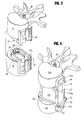
- FIG. 5is a perspective view, with the cage shown as a dotted line, of another embodiment of the spinal replacement device of this invention.
- FIG. 6is an exploded view of the spinal replacement device of FIG. 5, including the cage.
- FIG. 7is a perspective view of an open, helical bone screw which may be used in conjunction with the spinal replacement device of this invention.
- device 10comprises a tubular cage 12 of oval cross section and made for example of titanium or a carbon fiber composite.
- cage 12maybe made of a length of hollow bone typically having noncircular ends, cut to fit, and having a lumen that extends from end to end of the bone.
- Tubular cage 12fits into the space which is left by a missing vertebral body which was either destroyed or had to be surgically removed, positioned between a pair of adjacent, intact vertebral bodies 14 , 16 is as shown particularly in FIG. 2 .
- the major transverse cross sectional axis of oval tubular cage 12preferably extends from side to side of the spine comprising vertebra 14 , 16 .
- Cage 12is positioned anterior to the spinal cord 18 .
- Cage 12may be filled with bone fragments or other bone graft material so that, ultimately, an intact bone graft will be formed, extending between intact vertebra 14 , 16 .
- First and second transverse plates 20 , 22are respectively positioned at opposed ends of tubular cage 12 , for supporting the respective cage ends and for pressing a face 24 against an adjacent vertebral body 14 or 16 in spinal column-supporting relation.
- Transverse plates 20 , 22also define an aperture 26 , but, typically, the face 24 that presses against the intact, vertebral bodies 14 , 16 has more area than the area of each end of cage 12 , so that a greater surface area pressing against each vertebral body 14 , 16 is provided than would be provided by the mere presence of cage 12 .
- transverse plates 22 , 24define a peripheral, upstanding wall 28 , being dimensioned to cause tight retention of cage 12 .
- wall 28is open at one end of each transverse plate to receive the cage with lateral motion (relative to the spinal column).
- FIG. 2it can be seen how cage 12 may enter the area circumscribed by upstanding walls 28 by advancement of transverse plates approximately from the right toward the cage, or by advancement of cage 12 toward the left into engagement with transverse plates 20 , 22 .
- Transverse plates 20 , 22are each joined in transverse relation to at least one vertebral attachment plate.
- a pair of such vertebral attachment plates 30 , 32are used.
- vertebral attachment plates 30 , 32extend generally parallel to the spine i.e. generally parallel to the line of vertebra 14 , 16 , being integrally secured in this embodiment in transverse relation, each to a separate transverse plate 20 , 22 .
- each vertebral attachment plate 30 , 32defines first screw holes 33 for screw securance to one of the respective vertebral bodies 14 , 16 , as shown particularly in FIG. 2, for securance of the spinal vertebral replacement device in position.
- a rod 34extends generally parallel to the spine and is retained between vertical attachment plates 30 , 32 with a frictional pressure retention provided by cover plates 36 , 38 .
- Cover plates 36 , 38have screw holes 40 which mate with second screw holes 43 on the vertebral attachment plates 30 , 32 , for firm pressure attachment to provide a frictional pressure retention seal of rod 34 in the desired position.
- cover plates 36 , 38serve to restrict and prevent unintended back-out of the bone screws from their retained position within screw holes 33 of the respective vertebral attachment plates 30 , 32 .
- Appropriate grooves 42 , 44are respectively provided in the vertebral attachment plates 30 , 32 and the cover plates 36 , 38 to appropriately receive rod 34 .
- Rod 34may be cylindrical, but is preferably of non-circular cross section, to raise the torque resistance of the rod.
- rod 34may be of rectangular cross section with the major axis of the rectangle extending transversely from side-to-side of the spine in a direction generally parallel to the major cross-sectional axis of cage 12 .
- Cage 12may define an end aperture 45 at each end on the long axis thereof, to provide access for a distractor tool, used in the surgical installation of the system.
- an implantable anterial spinal fixatorin which one or more vertebrae can be replaced with the device of this invention.
- the devicefirmly maintains the spacing of missing vertebrae, and also provides the capability for the firm retention and growth of a bone graft, to restore to the spine a more natural, strong regrowth of bone.
- the systemis very flexible for use, and is capable of dimensional variations, for example by the use of varying lengths of the cage 12 .
- transverse plates 20 , 22may be connected to vertebral attachment plates 30 , 32 by a hinge, which provides added dimensional tolerance capability to the system.
- FIG. 4another embodiment of the implantable spinal vertebral replacement device of this invention is shown, with the device being shown to be implanted on the spine.
- first and second transverse plates 20 a , 22 aengage the ends of a tubular cage 12 a , and also press with their other faces against intact adjacent vertebral bodies 14 a , 16 a , all in a manner similar to the previous embodiment.
- Transverse plates 20 a , 22 aeach engage a single vertebral attachment plate 46 , instead of a pair of vertebral attachment plates as in the last embodiment.
- Vertebral attachment plate 46extends basically parallel to the spine as in the previous embodiment, and has pairs of bone screw attachment holes 34 a for attachment at the respective ends of vertebral attachment plate 46 to intact, adjacent vertebral bodies 14 a , 16 a.
- Transverse plate 20 asimply connects in a pressure connection to opposed edges of vertebral attachment plate 46 as shown. Particularly, the ends 48 of plate 20 a press against vertebral attachment plate 46 with spring pressure. Thus, plate 20 a can slide up and down the vertebral attachment plate 46 as may be desired for best positioning.
- transverse plate 22 athe same spring pressure attachment to vertebral attachment plate 46 may be used, but with a strap 50 extending across the ends of transverse plate 22 a , with retention screws 52 being used to hold strap 50 and plate 22 a together.
- cage 12 ais strongly held in a desired lateral position by the secured plate 22 a.
- cover plate similar to cover plate 38may be used instead of strap 50 by the simple expedient of providing an enlarged, central section to strap 50 to cover the respective end of vertebral attachment plate 46 .
- screw holes 34 amay be covered to prevent accidental, unintended back-out of the bone retention screws, in a manner similar to the previous embodiment.
- Transverse plate 22 acan also slide up and down the vertebral attachment plate to a desired position until tightly secured, so that the system of this invention has very substantial dimensional tolerance, and thus can be used with a variety of patients.
- another embodiment of the spinal replacement devicecomprises a pair of transverse plates 20 b , 22 b , similar in overall concept to transverse plates 20 , 22 and for a similar purpose.
- Each of plates 20 b , 22 bmay be of substantially identical design, having a peripheral upstanding wall 28 b and an end aperture 60 for access of a distractor tool, similar to the corresponding end apertures in plates 20 , 22 .
- Transverse plates 20 b , 22 bare generally U-shaped, ending in projections 62 which each define a screw hole 64 .
- a vertebral attachment plate 46 bis present, having end portions 66 , 67 , which are transversely enlarged relative to a central portion 68 between the end portions.
- Each of end portions 66 , 67respectively define screw apertures 70 , 72 to permit attachment of plate 46 b to separate vertebrae at each end of plate 46 b , by bone screws (not shown) respectively passing through screw holes 70 to engage one vertebrae and screw holes 72 to engage the other vertebrae.
- Cover plates 74 , 76can close off and protect the respective bone screws in apertures 70 , 72 , also serving to prevent backout of the bone screws from a more advanced, bone-retaining position. However, plates 74 , 76 also serve to respectively retain transverse, apertured plates 20 b , 22 b . Screw holes 78 of cover plate 74 can engage screw holes 64 of transverse plate 20 b to retain plate 20 b in firm engagement with vertical attachment plate 46 b , with screws 80 . Screws 80 do not pass through any aperture in vertical attachment plate 46 b . Rather, they pass along the central, narrower portion 68 of plate 46 b , on each side thereof, being prevented from sliding off by the transversely enlarged end portions 66 , 67 .
- transverse plate 20 bis securely retained to vertical attachment plate 46 b , but is in a slidable relationship therewith for fine adjustment of the system with respect to the vertebrae and also with respect to cage member 12 b , which maybe similar in structure and function to cage 12 , or may comprise apiece of bone as previously discussed.
- the cover plates 74 , 76have a peripheral portion that matches and lies against a periphery portion of the vertebral attachment plate 46 b.
- transverse plate 22 bmay be attached to cover plate 76 through the penetration of screws 82 extending through apertures 77 and 64 , for retention of cover plate 76 and transverse plate 22 b together in a position on vertebral attachment plate 46 b within the enlarged end portions 66 , 67 and prevented from sliding off plate 46 b by the enlargement of portions 66 , 67 .
- FIG. 5shows the assembled spinal replacement device, which may be positioned in relation to the spine in a manner similar to the previous embodiments, as particularly shown in FIGS. 2, 3 and 4 .
- the vertical positioning of transverse plates 20 b , 22 b along the spineis governed by the presence of cage 12 b (shown in dotted lines in FIG. 5) and the respective vertebrae analogous to vertebrae 14 a , 16 a in FIG. 4 .
- transverse plates 20 b , 22 bare held in an optimum position, with their spacing along vertebral attachment plate 46 b being governed at least in part by the geometry of cage 12 b and the positioning of the adjacent vertebrae portions analogous to 14 a and 16 a . Positional adjustments can spontaneously take place as needed, while collapse of the spine is prevented.
- FIG. 7one embodiment of an open, helical screw of the type previously described is shown.
- Such screwsare desirably used in each of the disclosed embodiments to secure the vertebral replacement device to at least a pair of vertebrae in the spine.
- such screwswill be used in the embodiment of FIG. 4 to pass through holes 34 a , to secure the entire device to the spine.
- such helical screwswill pass through holes 70 , 72 of plate 46 b for the same purpose of adherence to the spine, to achieve a system which exhibits advantages as described above.
- such helical screensmay extend through holes 33 .
- Open helical screw 86is just one embodiment of open helical screws which maybe utilized in this invention.
- This particular embodimentcarries a screw head 88 and a single, open helical screw shaft 90 .
- more than one helical shaftmaybe provided, as indicated by the presence of a second, optional helical shaft 92 , shown diagrammatically as a helical, dotted line which is approximately 180° out of rotational phase with helical shaft 90 .
- three or four such helical shaftsmay be provided, with the helices of said shafts being preferably in coaxial relation with each other.
- the shape of head 88 and the shape of the shaft cross sectionmay vary.
Landscapes
- Health & Medical Sciences (AREA)
- Orthopedic Medicine & Surgery (AREA)
- Engineering & Computer Science (AREA)
- Biomedical Technology (AREA)
- Neurology (AREA)
- Life Sciences & Earth Sciences (AREA)
- Animal Behavior & Ethology (AREA)
- Veterinary Medicine (AREA)
- Public Health (AREA)
- Heart & Thoracic Surgery (AREA)
- General Health & Medical Sciences (AREA)
- Cardiology (AREA)
- Vascular Medicine (AREA)
- Transplantation (AREA)
- Oral & Maxillofacial Surgery (AREA)
- Surgery (AREA)
- Nuclear Medicine, Radiotherapy & Molecular Imaging (AREA)
- Medical Informatics (AREA)
- Molecular Biology (AREA)
- Prostheses (AREA)
- Surgical Instruments (AREA)
Abstract
Description
Claims (16)
Priority Applications (1)
| Application Number | Priority Date | Filing Date | Title |
|---|---|---|---|
| US10/104,487US6682561B2 (en) | 1998-06-18 | 2002-03-25 | Spinal fixation system |
Applications Claiming Priority (3)
| Application Number | Priority Date | Filing Date | Title |
|---|---|---|---|
| US9931098A | 1998-06-18 | 1998-06-18 | |
| US09/561,248US6395030B1 (en) | 1998-06-18 | 2000-04-27 | Spinal fixation system |
| US10/104,487US6682561B2 (en) | 1998-06-18 | 2002-03-25 | Spinal fixation system |
Related Parent Applications (1)
| Application Number | Title | Priority Date | Filing Date |
|---|---|---|---|
| US09/561,248Continuation-In-PartUS6395030B1 (en) | 1998-06-18 | 2000-04-27 | Spinal fixation system |
Publications (2)
| Publication Number | Publication Date |
|---|---|
| US20020169508A1 US20020169508A1 (en) | 2002-11-14 |
| US6682561B2true US6682561B2 (en) | 2004-01-27 |
Family
ID=26795966
Family Applications (1)
| Application Number | Title | Priority Date | Filing Date |
|---|---|---|---|
| US10/104,487Expired - Fee RelatedUS6682561B2 (en) | 1998-06-18 | 2002-03-25 | Spinal fixation system |
Country Status (1)
| Country | Link |
|---|---|
| US (1) | US6682561B2 (en) |
Cited By (95)
| Publication number | Priority date | Publication date | Assignee | Title |
|---|---|---|---|---|
| US20040068318A1 (en)* | 2002-10-02 | 2004-04-08 | Coates Bradley J. | Modular intervertebral prosthesis system |
| US20040186577A1 (en)* | 2003-01-29 | 2004-09-23 | Ferree Bret A. | In situ artificaial disc replacements and other prosthetic components |
| US20050075634A1 (en)* | 2002-10-29 | 2005-04-07 | Zucherman James F. | Interspinous process implant with radiolucent spacer and lead-in tissue expander |
| US20050107877A1 (en)* | 2003-10-30 | 2005-05-19 | Nu Vasive, Inc. | System and methods for restoring the structural integrity of bone |
| US20050113919A1 (en)* | 2000-02-16 | 2005-05-26 | Cragg Andrew H. | Prosthetic nucleus apparatus |
| US20050143820A1 (en)* | 2003-12-02 | 2005-06-30 | St. Francis Medical Technologies, Inc. | Method of laterally inserting an artificial vertebral disk replacement implant with translating pivot point |
| US20050154459A1 (en)* | 2003-10-20 | 2005-07-14 | Howard Wolek | Vertebral body replacement apparatus and method |
| US20050256577A1 (en)* | 2002-09-18 | 2005-11-17 | Mathys Medizinaltechnik Ag | Implant comprising a two-piece joint |
| US20060058800A1 (en)* | 2002-12-03 | 2006-03-16 | Trans1 Inc. | Methods and apparatus for provision of therapy to adjacent motion segments |
| US20060074490A1 (en)* | 2004-10-01 | 2006-04-06 | Sweeney Patrick J | Vertebral prosthesis and spinal fixation system |
| US20060079898A1 (en)* | 2003-10-23 | 2006-04-13 | Trans1 Inc. | Spinal motion preservation assemblies |
| US20060149371A1 (en)* | 2004-12-10 | 2006-07-06 | Sdgi Holdings, Inc. | Intervertebral prosthetic device and method with locking mechanism |
| US20060155297A1 (en)* | 2003-10-23 | 2006-07-13 | Ainsworth Stephen D | Driver assembly for simultaneous axial delivery of spinal implants |
| WO2006047541A3 (en)* | 2003-10-23 | 2006-11-02 | Trans1 Inc | Spinal motion preservation assemblies |
| US20070162126A1 (en)* | 2005-12-01 | 2007-07-12 | Sdgi Holdings, Inc. | End device for a vertebral implant |
| US20070168036A1 (en)* | 2003-10-23 | 2007-07-19 | Trans1 Inc. | Spinal motion preservation assemblies |
| US20070173936A1 (en)* | 2006-01-23 | 2007-07-26 | Depuy Spine, Inc. | Intervertebral disc prosthesis |
| US20070299442A1 (en)* | 2006-06-26 | 2007-12-27 | Sdgi Holdings, Inc. | Vertebral stabilizer |
| US20080004707A1 (en)* | 2003-10-23 | 2008-01-03 | Cragg Andrew H | Prosthetic nucleus apparatus and method |
| US7320708B1 (en) | 2002-11-13 | 2008-01-22 | Sdgi Holdings, Inc. | Cervical interbody device |
| US20080021555A1 (en)* | 2006-07-19 | 2008-01-24 | John White | Expandable vertebral body implants and methods of use |
| WO2008011492A3 (en)* | 2006-07-21 | 2008-07-03 | Kinglsey R Chin | Spinal fusion assembly |
| US20080183294A1 (en)* | 2005-04-19 | 2008-07-31 | Ali Adl | Hinged Artificial Spinal Disk Drive |
| US20080262502A1 (en)* | 2006-10-24 | 2008-10-23 | Trans1, Inc. | Multi-membrane prosthetic nucleus |
| US20080311980A1 (en)* | 2001-12-21 | 2008-12-18 | Igt | Method and apparatus for competitive bonus games based upon strategy or skill |
| US20090062917A1 (en)* | 2007-08-27 | 2009-03-05 | Foley Kevin T | Spinal interbody replacement devices |
| US20090177207A1 (en)* | 2005-08-16 | 2009-07-09 | Laurent Schaller | Method of interdigitating flowable material with bone tissue |
| US20100106251A1 (en)* | 2008-10-24 | 2010-04-29 | Erich Kast | Implant for use between spiral vertebrae |
| US20100145462A1 (en)* | 2006-10-24 | 2010-06-10 | Trans1 Inc. | Preformed membranes for use in intervertebral disc spaces |
| US20100198274A1 (en)* | 2002-02-13 | 2010-08-05 | Jeffrey Eric Yeung | Intervertebral disc inserting device |
| US7799081B2 (en) | 2004-09-14 | 2010-09-21 | Aeolin, Llc | System and method for spinal fusion |
| US20100241231A1 (en)* | 2009-02-20 | 2010-09-23 | Marino James F | Intervertebral fixation device |
| US20100249937A1 (en)* | 2009-03-27 | 2010-09-30 | Spinal Elements, Inc. | Flanged interbody fusion device |
| US20100312346A1 (en)* | 2007-11-16 | 2010-12-09 | Thomas Kueenzi | Low profile intervertebral implant |
| US20110022173A1 (en)* | 2009-07-24 | 2011-01-27 | Warsaw Orthopedic, Inc. | Implant with an interference fit fastener |
| US7914531B1 (en) | 2004-10-06 | 2011-03-29 | Geller David S | Bone fixation system and methods |
| CN101808597B (en)* | 2008-10-24 | 2012-11-28 | 乌尔里克两合公司 | Implant for insertion between vertebral bodies of the spinal column |
| US8366773B2 (en) | 2005-08-16 | 2013-02-05 | Benvenue Medical, Inc. | Apparatus and method for treating bone |
| US8454694B2 (en) | 2011-03-03 | 2013-06-04 | Warsaw Orthopedic, Inc. | Interbody device and plate for spinal stabilization and instruments for positioning same |
| US8454617B2 (en) | 2005-08-16 | 2013-06-04 | Benvenue Medical, Inc. | Devices for treating the spine |
| US8480747B2 (en) | 2010-08-11 | 2013-07-09 | Warsaw Orthopedic, Inc. | Interbody spinal implants with extravertebral support plates |
| US8535327B2 (en) | 2009-03-17 | 2013-09-17 | Benvenue Medical, Inc. | Delivery apparatus for use with implantable medical devices |
| US20130282127A1 (en)* | 2007-05-22 | 2013-10-24 | Zimmer Spine, Inc. | Spinal implant system and method |
| US8591583B2 (en) | 2005-08-16 | 2013-11-26 | Benvenue Medical, Inc. | Devices for treating the spine |
| US8696721B2 (en) | 2005-03-17 | 2014-04-15 | Spinal Elements, Inc. | Orthopedic expansion fastener |
| US8740983B1 (en) | 2009-11-11 | 2014-06-03 | Nuvasive, Inc. | Spinal fusion implants and related methods |
| US8814873B2 (en) | 2011-06-24 | 2014-08-26 | Benvenue Medical, Inc. | Devices and methods for treating bone tissue |
| US8840668B1 (en) | 2009-11-11 | 2014-09-23 | Nuvasive, Inc. | Spinal implants, instruments and related methods |
| US8852280B2 (en) | 2007-09-27 | 2014-10-07 | Warsaw Orthopedic, Inc. | Intervertebral implant |
| US8956415B2 (en) | 2010-08-15 | 2015-02-17 | Warsaw Orthopedic, Inc. | Vertebral implant |
| US9192419B2 (en) | 2008-11-07 | 2015-11-24 | DePuy Synthes Products, Inc. | Zero-profile interbody spacer and coupled plate assembly |
| USD745159S1 (en) | 2013-10-10 | 2015-12-08 | Nuvasive, Inc. | Intervertebral implant |
| US9241809B2 (en) | 2010-12-21 | 2016-01-26 | DePuy Synthes Products, Inc. | Intervertebral implants, systems, and methods of use |
| US9463097B2 (en) | 2003-02-06 | 2016-10-11 | DePuy Synthes Products, Inc. | Intervertebral implant |
| US9572681B2 (en) | 2002-02-19 | 2017-02-21 | DePuy Synthes Products, Inc. | Intervertebral implant |
| US20170049579A1 (en)* | 2015-08-19 | 2017-02-23 | Raymond J. Quinlan | Spinal Fusion Device And Method Of Using Same |
| US9730804B2 (en) | 2009-09-06 | 2017-08-15 | Warsaw Orthopedic, Inc. | Locking spinal fusion device |
| US9788963B2 (en) | 2003-02-14 | 2017-10-17 | DePuy Synthes Products, Inc. | In-situ formed intervertebral fusion device and method |
| US9848992B2 (en) | 2010-12-21 | 2017-12-26 | DePuy Synthes Products, Inc. | Intervertebral implants, systems, and methods of use |
| US9867718B2 (en) | 2014-10-22 | 2018-01-16 | DePuy Synthes Products, Inc. | Intervertebral implants, systems, and methods of use |
| US9911286B2 (en) | 2003-10-20 | 2018-03-06 | Igt | Electronic gaming device which determines play information |
| US9968460B2 (en) | 2013-03-15 | 2018-05-15 | Medsmart Innovation Inc. | Dynamic spinal segment replacement |
| US10085783B2 (en) | 2013-03-14 | 2018-10-02 | Izi Medical Products, Llc | Devices and methods for treating bone tissue |
| USD858769S1 (en) | 2014-11-20 | 2019-09-03 | Nuvasive, Inc. | Intervertebral implant |
| US10512548B2 (en) | 2006-02-27 | 2019-12-24 | DePuy Synthes Products, Inc. | Intervertebral implant with fixation geometry |
| US10758361B2 (en) | 2015-01-27 | 2020-09-01 | Spinal Elements, Inc. | Facet joint implant |
| US10888433B2 (en) | 2016-12-14 | 2021-01-12 | DePuy Synthes Products, Inc. | Intervertebral implant inserter and related methods |
| US10940016B2 (en) | 2017-07-05 | 2021-03-09 | Medos International Sarl | Expandable intervertebral fusion cage |
| US10966840B2 (en) | 2010-06-24 | 2021-04-06 | DePuy Synthes Products, Inc. | Enhanced cage insertion assembly |
| US10973652B2 (en) | 2007-06-26 | 2021-04-13 | DePuy Synthes Products, Inc. | Highly lordosed fusion cage |
| US11273050B2 (en) | 2006-12-07 | 2022-03-15 | DePuy Synthes Products, Inc. | Intervertebral implant |
| US11344424B2 (en) | 2017-06-14 | 2022-05-31 | Medos International Sarl | Expandable intervertebral implant and related methods |
| US11382769B2 (en) | 2018-09-20 | 2022-07-12 | Spinal Elements, Inc. | Spinal implant device |
| US11426290B2 (en) | 2015-03-06 | 2022-08-30 | DePuy Synthes Products, Inc. | Expandable intervertebral implant, system, kit and method |
| US11426286B2 (en) | 2020-03-06 | 2022-08-30 | Eit Emerging Implant Technologies Gmbh | Expandable intervertebral implant |
| US11443596B2 (en) | 2013-07-09 | 2022-09-13 | Igt | Gaming system and method for resuming a skill-based game after an interruption event |
| US11446156B2 (en) | 2018-10-25 | 2022-09-20 | Medos International Sarl | Expandable intervertebral implant, inserter instrument, and related methods |
| US11446155B2 (en) | 2017-05-08 | 2022-09-20 | Medos International Sarl | Expandable cage |
| US11452607B2 (en) | 2010-10-11 | 2022-09-27 | DePuy Synthes Products, Inc. | Expandable interspinous process spacer implant |
| US11497619B2 (en) | 2013-03-07 | 2022-11-15 | DePuy Synthes Products, Inc. | Intervertebral implant |
| US11510788B2 (en) | 2016-06-28 | 2022-11-29 | Eit Emerging Implant Technologies Gmbh | Expandable, angularly adjustable intervertebral cages |
| US11596523B2 (en) | 2016-06-28 | 2023-03-07 | Eit Emerging Implant Technologies Gmbh | Expandable and angularly adjustable articulating intervertebral cages |
| US11602438B2 (en) | 2008-04-05 | 2023-03-14 | DePuy Synthes Products, Inc. | Expandable intervertebral implant |
| US11607321B2 (en) | 2009-12-10 | 2023-03-21 | DePuy Synthes Products, Inc. | Bellows-like expandable interbody fusion cage |
| US11612491B2 (en) | 2009-03-30 | 2023-03-28 | DePuy Synthes Products, Inc. | Zero profile spinal fusion cage |
| US11654033B2 (en) | 2010-06-29 | 2023-05-23 | DePuy Synthes Products, Inc. | Distractible intervertebral implant |
| US11737881B2 (en) | 2008-01-17 | 2023-08-29 | DePuy Synthes Products, Inc. | Expandable intervertebral implant and associated method of manufacturing the same |
| US11752009B2 (en) | 2021-04-06 | 2023-09-12 | Medos International Sarl | Expandable intervertebral fusion cage |
| US11850160B2 (en) | 2021-03-26 | 2023-12-26 | Medos International Sarl | Expandable lordotic intervertebral fusion cage |
| US11911284B2 (en) | 2020-11-19 | 2024-02-27 | Spinal Elements, Inc. | Curved expandable interbody devices and deployment tools |
| US11911287B2 (en) | 2010-06-24 | 2024-02-27 | DePuy Synthes Products, Inc. | Lateral spondylolisthesis reduction cage |
| USRE49973E1 (en) | 2013-02-28 | 2024-05-21 | DePuy Synthes Products, Inc. | Expandable intervertebral implant, system, kit and method |
| US12090064B2 (en) | 2022-03-01 | 2024-09-17 | Medos International Sarl | Stabilization members for expandable intervertebral implants, and related systems and methods |
| US12279969B2 (en) | 2020-12-17 | 2025-04-22 | Spinal Elements, Inc. | Spinal implant device |
| US12440346B2 (en) | 2023-03-31 | 2025-10-14 | DePuy Synthes Products, Inc. | Expandable intervertebral implant |
Families Citing this family (54)
| Publication number | Priority date | Publication date | Assignee | Title |
|---|---|---|---|---|
| US7169182B2 (en) | 2001-07-16 | 2007-01-30 | Spinecore, Inc. | Implanting an artificial intervertebral disc |
| US6673113B2 (en) | 2001-10-18 | 2004-01-06 | Spinecore, Inc. | Intervertebral spacer device having arch shaped spring elements |
| US7713302B2 (en) | 2001-10-01 | 2010-05-11 | Spinecore, Inc. | Intervertebral spacer device utilizing a spirally slotted belleville washer having radially spaced concentric grooves |
| US7771477B2 (en) | 2001-10-01 | 2010-08-10 | Spinecore, Inc. | Intervertebral spacer device utilizing a belleville washer having radially spaced concentric grooves |
| US8038713B2 (en) | 2002-04-23 | 2011-10-18 | Spinecore, Inc. | Two-component artificial disc replacements |
| US20080027548A9 (en) | 2002-04-12 | 2008-01-31 | Ferree Bret A | Spacerless artificial disc replacements |
| US6706068B2 (en) | 2002-04-23 | 2004-03-16 | Bret A. Ferree | Artificial disc replacements with natural kinematics |
| US7338525B2 (en)* | 2002-04-30 | 2008-03-04 | Ferree Bret A | Methods and apparatus for preventing the migration of intradiscal devices |
| US7192447B2 (en) | 2002-12-19 | 2007-03-20 | Synthes (Usa) | Intervertebral implant |
| AU2004220634B2 (en)* | 2003-03-06 | 2009-09-17 | Spinecore, Inc. | Instrumentation and methods for use in implanting a cervical disc replacement device |
| US6908484B2 (en) | 2003-03-06 | 2005-06-21 | Spinecore, Inc. | Cervical disc replacement |
| US7819903B2 (en) | 2003-03-31 | 2010-10-26 | Depuy Spine, Inc. | Spinal fixation plate |
| US7563281B2 (en)* | 2003-04-03 | 2009-07-21 | Warsaw Orthopedic, Inc. | Apparatus and method for supporting vertebral bodies |
| US8012212B2 (en)* | 2003-04-07 | 2011-09-06 | Nuvasive, Inc. | Cervical intervertebral disk prosthesis |
| BRPI0409091A (en)* | 2003-04-07 | 2006-04-11 | Cervitech Inc | intervertebral joint prosthesis for the cervical spine |
| CN100484499C (en) | 2003-04-14 | 2009-05-06 | 斯恩蒂斯有限公司 | Intervertebral implant |
| US7938858B2 (en)* | 2003-09-15 | 2011-05-10 | Warsaw Orthopedic, Inc. | Spinal implant system |
| US7819922B2 (en)* | 2003-10-16 | 2010-10-26 | Spinal Generations, Llc | Vertebral prosthesis |
| US7771479B2 (en) | 2004-01-09 | 2010-08-10 | Warsaw Orthopedic, Inc. | Dual articulating spinal device and method |
| US20050171608A1 (en) | 2004-01-09 | 2005-08-04 | Sdgi Holdings, Inc. | Centrally articulating spinal device and method |
| US7621938B2 (en)* | 2004-01-15 | 2009-11-24 | Warsaw Orthopedic, Inc. | Spinal implant construct and method for implantation |
| GB2410189A (en)* | 2004-01-23 | 2005-07-27 | Corin Ltd | Intervertebral disc prosthesis |
| US8777959B2 (en) | 2005-05-27 | 2014-07-15 | Spinecore, Inc. | Intervertebral disc and insertion methods therefor |
| US8764832B2 (en)* | 2005-09-26 | 2014-07-01 | Warsaw Orhtopedic, Inc. | Anterior hybrid implant |
| US7811326B2 (en) | 2006-01-30 | 2010-10-12 | Warsaw Orthopedic Inc. | Posterior joint replacement device |
| US7635389B2 (en) | 2006-01-30 | 2009-12-22 | Warsaw Orthopedic, Inc. | Posterior joint replacement device |
| US20070191848A1 (en)* | 2006-02-01 | 2007-08-16 | Zimmer Technology, Inc. | Hydrogel bone plate spacer |
| US20070288020A1 (en)* | 2006-06-02 | 2007-12-13 | United Orthopedic Corporation | Soft tissue fixation device for organs proximate shankbone |
| US8092534B2 (en)* | 2006-11-16 | 2012-01-10 | Warsaw Orthopedic, Inc. | Revision device |
| US8268000B2 (en)* | 2007-04-03 | 2012-09-18 | Warsaw Orthopedic, Inc. | Composite interbody spacer |
| US8425607B2 (en)* | 2007-04-03 | 2013-04-23 | Warsaw Orthopedic, Inc. | Anchor member locking features |
| US20080249569A1 (en)* | 2007-04-03 | 2008-10-09 | Warsaw Orthopedic, Inc. | Implant Face Plates |
| US8864832B2 (en) | 2007-06-20 | 2014-10-21 | Hh Spinal Llc | Posterior total joint replacement |
| US10821003B2 (en) | 2007-06-20 | 2020-11-03 | 3Spline Sezc | Spinal osteotomy |
| FR2926457A1 (en)* | 2008-01-17 | 2009-07-24 | Warsaw Orthopedic Inc | INTERVERTEBRAL CAGE AND VERTEBRAL FUSION DEVICE HAVING THE SAME |
| AU2009205679B2 (en) | 2008-01-18 | 2013-12-05 | Spinecore, Inc. | Instruments and methods for inserting artificial intervertebral implants |
| FR2929829B1 (en)* | 2008-04-09 | 2011-09-16 | Warsaw Orthopedic Inc | CONNECTION SYSTEM BETWEEN AN IMPLANT REPLACING A VERTEBRAL BODY AND A FIXATION INSTRUMENTATION |
| EP2355751A4 (en)* | 2008-11-14 | 2013-07-10 | David Krueger | Spinal fusion device |
| US9526628B2 (en) | 2008-11-14 | 2016-12-27 | David Krueger | Spinal fusion device |
| US9474625B2 (en)* | 2010-09-03 | 2016-10-25 | Globus Medical, Inc | Expandable fusion device and method of installation thereof |
| USD700332S1 (en)* | 2012-12-18 | 2014-02-25 | Tyber Medical Llc | Intervertebral implant |
| US9180022B2 (en)* | 2013-06-28 | 2015-11-10 | DePuy Synthes Products, Inc. | Spinal alignment clip |
| US9615931B2 (en)* | 2015-03-20 | 2017-04-11 | Globus Medical, Inc. | Surgical plate systems |
| WO2017147619A1 (en)* | 2016-02-28 | 2017-08-31 | Life Spine, Inc. | Expandable corpectomy spine implant |
| WO2018112324A2 (en) | 2016-12-16 | 2018-06-21 | Advance Research System, Llc | Interbody implant with concave profiled nose |
| USD879295S1 (en) | 2017-02-13 | 2020-03-24 | Advance Research System, Llc | Spinal fusion cage |
| USD847339S1 (en)* | 2017-06-26 | 2019-04-30 | Advanced Research System, LLC | Spinal fusion cage |
| USD847340S1 (en)* | 2017-10-25 | 2019-04-30 | Ikon Spine LLC | Transforaminal lumbar interbody fusion device |
| USD847341S1 (en)* | 2017-10-31 | 2019-04-30 | Warsaw Orthopedic, Inc. | Spinal implant |
| USD847996S1 (en)* | 2017-10-31 | 2019-05-07 | Warsaw Orthopedic, Inc. | Spinal implant |
| USD847342S1 (en)* | 2017-10-31 | 2019-04-30 | Warsaw Orthopedic, Inc. | Spinal implant |
| USD847995S1 (en)* | 2017-10-31 | 2019-05-07 | Warsaw Orthopedic, Inc. | Spinal implant |
| US11737888B1 (en) | 2019-09-19 | 2023-08-29 | Advance Research System, Llc | Spinal fusion implant system and method |
| US12409046B2 (en) | 2022-04-12 | 2025-09-09 | 3Spine, Inc. | Total spinal joint systems with motion moderators |
Citations (31)
| Publication number | Priority date | Publication date | Assignee | Title |
|---|---|---|---|---|
| US4289123A (en) | 1980-03-31 | 1981-09-15 | Dunn Harold K | Orthopedic appliance |
| US4401112A (en) | 1980-09-15 | 1983-08-30 | Rezaian Seyed M | Spinal fixator |
| US4554914A (en) | 1983-10-04 | 1985-11-26 | Kapp John P | Prosthetic vertebral body |
| US4599086A (en) | 1985-06-07 | 1986-07-08 | Doty James R | Spine stabilization device and method |
| US4636217A (en) | 1985-04-23 | 1987-01-13 | Regents Of The University Of Minnesota | Anterior spinal implant |
| US4743256A (en) | 1985-10-04 | 1988-05-10 | Brantigan John W | Surgical prosthetic implant facilitating vertebral interbody fusion and method |
| US4759769A (en) | 1987-02-12 | 1988-07-26 | Health & Research Services Inc. | Artificial spinal disc |
| US4892545A (en) | 1988-07-14 | 1990-01-09 | Ohio Medical Instrument Company, Inc. | Vertebral lock |
| EP0374088A1 (en)* | 1988-12-16 | 1990-06-20 | GebràDer Sulzer Aktiengesellschaft | Bone screw |
| US5059193A (en) | 1989-11-20 | 1991-10-22 | Spine-Tech, Inc. | Expandable spinal implant and surgical method |
| US5147363A (en) | 1989-12-21 | 1992-09-15 | Haerle Anton | Screw for use in osteosynthesis |
| US5147360A (en) | 1990-02-19 | 1992-09-15 | Societe De Fabrication De Materiel Orthopedique | Osteosynthesis device for the correction of spinal curvatures |
| US5192327A (en) | 1991-03-22 | 1993-03-09 | Brantigan John W | Surgical prosthetic implant for vertebrae |
| US5261911A (en) | 1991-06-18 | 1993-11-16 | Allen Carl | Anterolateral spinal fixation system |
| US5304210A (en) | 1992-01-28 | 1994-04-19 | Amei Technologies Inc. | Apparatus for distributed bone growth stimulation |
| US5306309A (en) | 1992-05-04 | 1994-04-26 | Calcitek, Inc. | Spinal disk implant and implantation kit |
| US5306307A (en) | 1991-07-22 | 1994-04-26 | Calcitek, Inc. | Spinal disk implant |
| US5360430A (en) | 1993-07-29 | 1994-11-01 | Lin Chih I | Intervertebral locking device |
| US5425773A (en) | 1992-01-06 | 1995-06-20 | Danek Medical, Inc. | Intervertebral disk arthroplasty device |
| US5458641A (en) | 1993-09-08 | 1995-10-17 | Ramirez Jimenez; Juan J. | Vertebral body prosthesis |
| US5556431A (en) | 1992-03-13 | 1996-09-17 | B+E,Uml U+Ee Ttner-Janz; Karin | Intervertebral disc endoprosthesis |
| US5591235A (en) | 1995-03-15 | 1997-01-07 | Kuslich; Stephen D. | Spinal fixation device |
| US5603713A (en) | 1991-09-24 | 1997-02-18 | Aust; Gilbert M. | Anterior lumbar/cervical bicortical compression plate |
| US5662683A (en)* | 1995-08-22 | 1997-09-02 | Ortho Helix Limited | Open helical organic tissue anchor and method of facilitating healing |
| US5674296A (en) | 1994-11-14 | 1997-10-07 | Spinal Dynamics Corporation | Human spinal disc prosthesis |
| US5702453A (en)* | 1994-12-09 | 1997-12-30 | Sofamor Danek Group | Adjustable vertebral body replacement |
| US5755796A (en) | 1996-06-06 | 1998-05-26 | Ibo; Ivo | Prosthesis of the cervical intervertebralis disk |
| US5888223A (en) | 1995-12-08 | 1999-03-30 | Bray, Jr.; Robert S. | Anterior stabilization device |
| US5916267A (en)* | 1997-04-07 | 1999-06-29 | Arthit Sitiso | Anterior spinal implant system for vertebral body prosthesis |
| US6106557A (en)* | 1998-07-23 | 2000-08-22 | Howmedica Gmbh | Reconstruction system for vertebra |
| US6190413B1 (en)* | 1998-04-16 | 2001-02-20 | Ulrich Gmbh & Co. Kg | Vertebral implant |
- 2002
- 2002-03-25USUS10/104,487patent/US6682561B2/ennot_activeExpired - Fee Related
Patent Citations (31)
| Publication number | Priority date | Publication date | Assignee | Title |
|---|---|---|---|---|
| US4289123A (en) | 1980-03-31 | 1981-09-15 | Dunn Harold K | Orthopedic appliance |
| US4401112A (en) | 1980-09-15 | 1983-08-30 | Rezaian Seyed M | Spinal fixator |
| US4554914A (en) | 1983-10-04 | 1985-11-26 | Kapp John P | Prosthetic vertebral body |
| US4636217A (en) | 1985-04-23 | 1987-01-13 | Regents Of The University Of Minnesota | Anterior spinal implant |
| US4599086A (en) | 1985-06-07 | 1986-07-08 | Doty James R | Spine stabilization device and method |
| US4743256A (en) | 1985-10-04 | 1988-05-10 | Brantigan John W | Surgical prosthetic implant facilitating vertebral interbody fusion and method |
| US4759769A (en) | 1987-02-12 | 1988-07-26 | Health & Research Services Inc. | Artificial spinal disc |
| US4892545A (en) | 1988-07-14 | 1990-01-09 | Ohio Medical Instrument Company, Inc. | Vertebral lock |
| EP0374088A1 (en)* | 1988-12-16 | 1990-06-20 | GebràDer Sulzer Aktiengesellschaft | Bone screw |
| US5059193A (en) | 1989-11-20 | 1991-10-22 | Spine-Tech, Inc. | Expandable spinal implant and surgical method |
| US5147363A (en) | 1989-12-21 | 1992-09-15 | Haerle Anton | Screw for use in osteosynthesis |
| US5147360A (en) | 1990-02-19 | 1992-09-15 | Societe De Fabrication De Materiel Orthopedique | Osteosynthesis device for the correction of spinal curvatures |
| US5192327A (en) | 1991-03-22 | 1993-03-09 | Brantigan John W | Surgical prosthetic implant for vertebrae |
| US5261911A (en) | 1991-06-18 | 1993-11-16 | Allen Carl | Anterolateral spinal fixation system |
| US5306307A (en) | 1991-07-22 | 1994-04-26 | Calcitek, Inc. | Spinal disk implant |
| US5603713A (en) | 1991-09-24 | 1997-02-18 | Aust; Gilbert M. | Anterior lumbar/cervical bicortical compression plate |
| US5425773A (en) | 1992-01-06 | 1995-06-20 | Danek Medical, Inc. | Intervertebral disk arthroplasty device |
| US5304210A (en) | 1992-01-28 | 1994-04-19 | Amei Technologies Inc. | Apparatus for distributed bone growth stimulation |
| US5556431A (en) | 1992-03-13 | 1996-09-17 | B+E,Uml U+Ee Ttner-Janz; Karin | Intervertebral disc endoprosthesis |
| US5306309A (en) | 1992-05-04 | 1994-04-26 | Calcitek, Inc. | Spinal disk implant and implantation kit |
| US5360430A (en) | 1993-07-29 | 1994-11-01 | Lin Chih I | Intervertebral locking device |
| US5458641A (en) | 1993-09-08 | 1995-10-17 | Ramirez Jimenez; Juan J. | Vertebral body prosthesis |
| US5674296A (en) | 1994-11-14 | 1997-10-07 | Spinal Dynamics Corporation | Human spinal disc prosthesis |
| US5702453A (en)* | 1994-12-09 | 1997-12-30 | Sofamor Danek Group | Adjustable vertebral body replacement |
| US5591235A (en) | 1995-03-15 | 1997-01-07 | Kuslich; Stephen D. | Spinal fixation device |
| US5662683A (en)* | 1995-08-22 | 1997-09-02 | Ortho Helix Limited | Open helical organic tissue anchor and method of facilitating healing |
| US5888223A (en) | 1995-12-08 | 1999-03-30 | Bray, Jr.; Robert S. | Anterior stabilization device |
| US5755796A (en) | 1996-06-06 | 1998-05-26 | Ibo; Ivo | Prosthesis of the cervical intervertebralis disk |
| US5916267A (en)* | 1997-04-07 | 1999-06-29 | Arthit Sitiso | Anterior spinal implant system for vertebral body prosthesis |
| US6190413B1 (en)* | 1998-04-16 | 2001-02-20 | Ulrich Gmbh & Co. Kg | Vertebral implant |
| US6106557A (en)* | 1998-07-23 | 2000-08-22 | Howmedica Gmbh | Reconstruction system for vertebra |
Non-Patent Citations (8)
| Title |
|---|
| Article by Edmund T. Dombrowski, Jr. MD: "Rezaian Fixator in the Anterior Stabilization of Unstable Spine" from Orthopaedic Review Vo. XV, No. 1, Jan., 1986, pp. 30-34. |
| Article from Chapter 19/Application of Rezaian Anterior Fixation System by S.M. Rezaian, "Application of Rezaian Anterior Fixation System for the Management of Fractures of Thoracolumbar Spine", pp. 193-199. |
| Article from: 43rd Annual Meeting, Orthopaedic Research Society, Feb. 9-13, 1997, pp. 382: "Comparative Kinematics of a collapsible and Rigid Anterior Devices" by Goel et al., Iowa Spine Research Center, University of Iowa. |
| Article from: AcroMed Surgeon-driven spinal solutions: "Thoracolumbar Trauma & Tumor" dated Jul. 1995; 12 pages. |
| Article from: Acromed The Leader in spinal technology: "Kaneda SR (Smooth Rod) Anterior Spinal System, Titanium", 1994, AcroMed Corporation, 6 pages. |
| Article from: AcroMed The leader in Spinal technology: University AM Plate Titanium Anterior System, AcroMed Corporation 9/94, 5 pages. |
| Article from: SPINE vol. 22, No. 6, pp 686-690, 1997, Lippincott-Raven Publishers,"Anterolateral Dynamized Instrumentation and Fusion for Unstable Thoracolumbar and Lumbar Burst Fractures" by Carl et al. |
| SPINE vol. 23, No. 5, pp. 543-550, Article: "Stability Potential of Spinal Instrumentations in Tumor Vertebral Body Replacement Surgery" by Vahldiek et al, 1998. |
Cited By (248)
| Publication number | Priority date | Publication date | Assignee | Title |
|---|---|---|---|---|
| US20080188895A1 (en)* | 2000-02-16 | 2008-08-07 | Cragg Andrew H | Spinal mobility preservation apparatus |
| US7905905B2 (en) | 2000-02-16 | 2011-03-15 | Trans1, Inc. | Spinal mobility preservation apparatus |
| US7717958B2 (en) | 2000-02-16 | 2010-05-18 | Trans1, Inc. | Prosthetic nucleus apparatus |
| US7662173B2 (en) | 2000-02-16 | 2010-02-16 | Transl, Inc. | Spinal mobility preservation apparatus |
| US20050113919A1 (en)* | 2000-02-16 | 2005-05-26 | Cragg Andrew H. | Prosthetic nucleus apparatus |
| US7905908B2 (en) | 2000-02-16 | 2011-03-15 | Trans1, Inc. | Spinal mobility preservation method |
| US20080311980A1 (en)* | 2001-12-21 | 2008-12-18 | Igt | Method and apparatus for competitive bonus games based upon strategy or skill |
| US20100198274A1 (en)* | 2002-02-13 | 2010-08-05 | Jeffrey Eric Yeung | Intervertebral disc inserting device |
| US10492922B2 (en) | 2002-02-19 | 2019-12-03 | DePuy Synthes Products, Inc. | Intervertebral implant |
| US9572681B2 (en) | 2002-02-19 | 2017-02-21 | DePuy Synthes Products, Inc. | Intervertebral implant |
| US20050256577A1 (en)* | 2002-09-18 | 2005-11-17 | Mathys Medizinaltechnik Ag | Implant comprising a two-piece joint |
| US7537614B2 (en)* | 2002-09-18 | 2009-05-26 | Synthes Usa, Llc | Implant comprising a two-piece joint |
| US8092540B2 (en) | 2002-09-18 | 2012-01-10 | Synthes Usa, Llc | Implant comprising a two-piece joint |
| US6899735B2 (en)* | 2002-10-02 | 2005-05-31 | Sdgi Holdings, Inc. | Modular intervertebral prosthesis system |
| US20040068318A1 (en)* | 2002-10-02 | 2004-04-08 | Coates Bradley J. | Modular intervertebral prosthesis system |
| US20050075634A1 (en)* | 2002-10-29 | 2005-04-07 | Zucherman James F. | Interspinous process implant with radiolucent spacer and lead-in tissue expander |
| US7320708B1 (en) | 2002-11-13 | 2008-01-22 | Sdgi Holdings, Inc. | Cervical interbody device |
| US20060058800A1 (en)* | 2002-12-03 | 2006-03-16 | Trans1 Inc. | Methods and apparatus for provision of therapy to adjacent motion segments |
| US8167947B2 (en) | 2002-12-03 | 2012-05-01 | Trans1 Inc. | Methods for push distraction and for provision of therapy to adjacent motion segments |
| US7776042B2 (en) | 2002-12-03 | 2010-08-17 | Trans1 Inc. | Methods and apparatus for provision of therapy to adjacent motion segments |
| US8328847B2 (en) | 2002-12-03 | 2012-12-11 | Trans1 Inc. | Assemblies for provision of therapy to motion segments |
| US8523918B2 (en) | 2002-12-03 | 2013-09-03 | Baxano Surgical, Inc. | Therapy to adjacent motion segments |
| US20040186577A1 (en)* | 2003-01-29 | 2004-09-23 | Ferree Bret A. | In situ artificaial disc replacements and other prosthetic components |
| US10660765B2 (en) | 2003-02-06 | 2020-05-26 | DePuy Synthes Products, Inc. | Intervertebral implant |
| US9463097B2 (en) | 2003-02-06 | 2016-10-11 | DePuy Synthes Products, Inc. | Intervertebral implant |
| US10064740B2 (en) | 2003-02-06 | 2018-09-04 | DePuy Synthes Products, LLC | Intervertebral implant |
| US11207187B2 (en) | 2003-02-14 | 2021-12-28 | DePuy Synthes Products, Inc. | In-situ formed intervertebral fusion device and method |
| US10575959B2 (en) | 2003-02-14 | 2020-03-03 | DePuy Synthes Products, Inc. | In-situ formed intervertebral fusion device and method |
| US10786361B2 (en) | 2003-02-14 | 2020-09-29 | DePuy Synthes Products, Inc. | In-situ formed intervertebral fusion device and method |
| US9801729B2 (en) | 2003-02-14 | 2017-10-31 | DePuy Synthes Products, Inc. | In-situ formed intervertebral fusion device and method |
| US11096794B2 (en) | 2003-02-14 | 2021-08-24 | DePuy Synthes Products, Inc. | In-situ formed intervertebral fusion device and method |
| US9788963B2 (en) | 2003-02-14 | 2017-10-17 | DePuy Synthes Products, Inc. | In-situ formed intervertebral fusion device and method |
| US9814589B2 (en) | 2003-02-14 | 2017-11-14 | DePuy Synthes Products, Inc. | In-situ formed intervertebral fusion device and method |
| US9808351B2 (en) | 2003-02-14 | 2017-11-07 | DePuy Synthes Products, Inc. | In-situ formed intervertebral fusion device and method |
| US9925060B2 (en) | 2003-02-14 | 2018-03-27 | DePuy Synthes Products, Inc. | In-situ formed intervertebral fusion device and method |
| US10639164B2 (en) | 2003-02-14 | 2020-05-05 | DePuy Synthes Products, Inc. | In-situ formed intervertebral fusion device and method |
| US10583013B2 (en) | 2003-02-14 | 2020-03-10 | DePuy Synthes Products, Inc. | In-situ formed intervertebral fusion device and method |
| US10085843B2 (en) | 2003-02-14 | 2018-10-02 | DePuy Synthes Products, Inc. | In-situ formed intervertebral fusion device and method |
| US10555817B2 (en) | 2003-02-14 | 2020-02-11 | DePuy Synthes Products, Inc. | In-situ formed intervertebral fusion device and method |
| US10376372B2 (en) | 2003-02-14 | 2019-08-13 | DePuy Synthes Products, Inc. | In-situ formed intervertebral fusion device and method |
| US10492918B2 (en) | 2003-02-14 | 2019-12-03 | DePuy Synthes Products, Inc. | In-situ formed intervertebral fusion device and method |
| US10433971B2 (en) | 2003-02-14 | 2019-10-08 | DePuy Synthes Products, Inc. | In-situ formed intervertebral fusion device and method |
| US9814590B2 (en) | 2003-02-14 | 2017-11-14 | DePuy Synthes Products, Inc. | In-situ formed intervertebral fusion device and method |
| US10420651B2 (en) | 2003-02-14 | 2019-09-24 | DePuy Synthes Products, Inc. | In-situ formed intervertebral fusion device and method |
| US10405986B2 (en) | 2003-02-14 | 2019-09-10 | DePuy Synthes Products, Inc. | In-situ formed intervertebral fusion device and method |
| US11432938B2 (en) | 2003-02-14 | 2022-09-06 | DePuy Synthes Products, Inc. | In-situ intervertebral fusion device and method |
| US20050154459A1 (en)* | 2003-10-20 | 2005-07-14 | Howard Wolek | Vertebral body replacement apparatus and method |
| US7776093B2 (en)* | 2003-10-20 | 2010-08-17 | Blackstone Medical, Inc. | Vertebral body replacement apparatus and method |
| US9911286B2 (en) | 2003-10-20 | 2018-03-06 | Igt | Electronic gaming device which determines play information |
| US20050187625A1 (en)* | 2003-10-20 | 2005-08-25 | Howard Wolek | Vertebral body replacement apparatus and method |
| US20080195156A1 (en)* | 2003-10-23 | 2008-08-14 | Trans1 Inc. | Methods for Deploying Spinal Motion Preservation Assemblies |
| US7938836B2 (en) | 2003-10-23 | 2011-05-10 | Trans1, Inc. | Driver assembly for simultaneous axial delivery of spinal implants |
| US8038680B2 (en) | 2003-10-23 | 2011-10-18 | Trans1 Inc. | Drivers for inserts to bone anchors |
| US7776068B2 (en) | 2003-10-23 | 2010-08-17 | Trans1 Inc. | Spinal motion preservation assemblies |
| US20060079898A1 (en)* | 2003-10-23 | 2006-04-13 | Trans1 Inc. | Spinal motion preservation assemblies |
| US20080004707A1 (en)* | 2003-10-23 | 2008-01-03 | Cragg Andrew H | Prosthetic nucleus apparatus and method |
| US7601171B2 (en) | 2003-10-23 | 2009-10-13 | Trans1 Inc. | Spinal motion preservation assemblies |
| WO2006047541A3 (en)* | 2003-10-23 | 2006-11-02 | Trans1 Inc | Spinal motion preservation assemblies |
| US20060155297A1 (en)* | 2003-10-23 | 2006-07-13 | Ainsworth Stephen D | Driver assembly for simultaneous axial delivery of spinal implants |
| US20070167951A1 (en)* | 2003-10-23 | 2007-07-19 | Trans1 Inc. | Methods and tools for delivery of spinal motion preservation assemblies |
| US20070168036A1 (en)* | 2003-10-23 | 2007-07-19 | Trans1 Inc. | Spinal motion preservation assemblies |
| US20050107877A1 (en)* | 2003-10-30 | 2005-05-19 | Nu Vasive, Inc. | System and methods for restoring the structural integrity of bone |
| US20050143820A1 (en)* | 2003-12-02 | 2005-06-30 | St. Francis Medical Technologies, Inc. | Method of laterally inserting an artificial vertebral disk replacement implant with translating pivot point |
| US7503935B2 (en)* | 2003-12-02 | 2009-03-17 | Kyphon Sarl | Method of laterally inserting an artificial vertebral disk replacement with translating pivot point |
| US20100280622A1 (en)* | 2004-09-14 | 2010-11-04 | Aeolin, Llc | System and method for spinal fusion |
| US8562683B2 (en) | 2004-09-14 | 2013-10-22 | Aeolin Llc | System and method for spinal fusion |
| US7799081B2 (en) | 2004-09-14 | 2010-09-21 | Aeolin, Llc | System and method for spinal fusion |
| US20110035009A1 (en)* | 2004-10-01 | 2011-02-10 | Spinal Generations, Llc | Vertebral prosthesis and spinal fixation system |
| US7883543B2 (en) | 2004-10-01 | 2011-02-08 | Spinal Generations, Llc | Vertebral prosthesis and spinal fixation system |
| US20060074490A1 (en)* | 2004-10-01 | 2006-04-06 | Sweeney Patrick J | Vertebral prosthesis and spinal fixation system |
| US9980820B2 (en) | 2004-10-01 | 2018-05-29 | Spinal Generations, Llc | Vertebral prosthesis and spinal fixation system |
| US7914531B1 (en) | 2004-10-06 | 2011-03-29 | Geller David S | Bone fixation system and methods |
| US20060149371A1 (en)* | 2004-12-10 | 2006-07-06 | Sdgi Holdings, Inc. | Intervertebral prosthetic device and method with locking mechanism |
| US9265546B2 (en) | 2005-03-17 | 2016-02-23 | Spinal Elements, Inc. | Side-biased orthopedic fastener retention |
| US8801794B2 (en) | 2005-03-17 | 2014-08-12 | Spinal Elements, Inc. | Flanged interbody fusion device with fastener insert and retaining ring |
| US8696721B2 (en) | 2005-03-17 | 2014-04-15 | Spinal Elements, Inc. | Orthopedic expansion fastener |
| US9585707B2 (en) | 2005-03-17 | 2017-03-07 | Spinal Elements, Inc. | Flanged interbody fusion device with fastener insert and retaining ring |
| US9936984B2 (en) | 2005-03-17 | 2018-04-10 | Spinal Elements, Inc. | Flanged interbody fusion device with fastener insert and retaining ring |
| US20080183294A1 (en)* | 2005-04-19 | 2008-07-31 | Ali Adl | Hinged Artificial Spinal Disk Drive |
| US8357200B2 (en)* | 2005-04-19 | 2013-01-22 | Ali Adl | Hinged artificial spinal disk device |
| US8961609B2 (en) | 2005-08-16 | 2015-02-24 | Benvenue Medical, Inc. | Devices for distracting tissue layers of the human spine |
| US8366773B2 (en) | 2005-08-16 | 2013-02-05 | Benvenue Medical, Inc. | Apparatus and method for treating bone |
| US9788974B2 (en) | 2005-08-16 | 2017-10-17 | Benvenue Medical, Inc. | Spinal tissue distraction devices |
| US8454617B2 (en) | 2005-08-16 | 2013-06-04 | Benvenue Medical, Inc. | Devices for treating the spine |
| US7963993B2 (en) | 2005-08-16 | 2011-06-21 | Benvenue Medical, Inc. | Methods of distracting tissue layers of the human spine |
| US7967865B2 (en) | 2005-08-16 | 2011-06-28 | Benvenue Medical, Inc. | Devices for limiting the movement of material introduced between layers of spinal tissue |
| US20090177207A1 (en)* | 2005-08-16 | 2009-07-09 | Laurent Schaller | Method of interdigitating flowable material with bone tissue |
| US7967864B2 (en) | 2005-08-16 | 2011-06-28 | Benvenue Medical, Inc. | Spinal tissue distraction devices |
| US8556978B2 (en) | 2005-08-16 | 2013-10-15 | Benvenue Medical, Inc. | Devices and methods for treating the vertebral body |
| US9326866B2 (en) | 2005-08-16 | 2016-05-03 | Benvenue Medical, Inc. | Devices for treating the spine |
| US7666226B2 (en) | 2005-08-16 | 2010-02-23 | Benvenue Medical, Inc. | Spinal tissue distraction devices |
| US8591583B2 (en) | 2005-08-16 | 2013-11-26 | Benvenue Medical, Inc. | Devices for treating the spine |
| US7666227B2 (en) | 2005-08-16 | 2010-02-23 | Benvenue Medical, Inc. | Devices for limiting the movement of material introduced between layers of spinal tissue |
| US7670375B2 (en) | 2005-08-16 | 2010-03-02 | Benvenue Medical, Inc. | Methods for limiting the movement of material introduced between layers of spinal tissue |
| US7785368B2 (en) | 2005-08-16 | 2010-08-31 | Benvenue Medical, Inc. | Spinal tissue distraction devices |
| US8801787B2 (en) | 2005-08-16 | 2014-08-12 | Benvenue Medical, Inc. | Methods of distracting tissue layers of the human spine |
| US8057544B2 (en) | 2005-08-16 | 2011-11-15 | Benvenue Medical, Inc. | Methods of distracting tissue layers of the human spine |
| US8808376B2 (en) | 2005-08-16 | 2014-08-19 | Benvenue Medical, Inc. | Intravertebral implants |
| US7670374B2 (en) | 2005-08-16 | 2010-03-02 | Benvenue Medical, Inc. | Methods of distracting tissue layers of the human spine |
| US9259326B2 (en) | 2005-08-16 | 2016-02-16 | Benvenue Medical, Inc. | Spinal tissue distraction devices |
| US10028840B2 (en) | 2005-08-16 | 2018-07-24 | Izi Medical Products, Llc | Spinal tissue distraction devices |
| US9066808B2 (en) | 2005-08-16 | 2015-06-30 | Benvenue Medical, Inc. | Method of interdigitating flowable material with bone tissue |
| US8882836B2 (en) | 2005-08-16 | 2014-11-11 | Benvenue Medical, Inc. | Apparatus and method for treating bone |
| US20100174321A1 (en)* | 2005-08-16 | 2010-07-08 | Laurent Schaller | Methods of Distracting Tissue Layers of the Human Spine |
| US9044338B2 (en) | 2005-08-16 | 2015-06-02 | Benvenue Medical, Inc. | Spinal tissue distraction devices |
| US7955391B2 (en) | 2005-08-16 | 2011-06-07 | Benvenue Medical, Inc. | Methods for limiting the movement of material introduced between layers of spinal tissue |
| US8979929B2 (en) | 2005-08-16 | 2015-03-17 | Benvenue Medical, Inc. | Spinal tissue distraction devices |
| US20100174375A1 (en)* | 2005-08-16 | 2010-07-08 | Laurent Schaller | Spinal Tissue Distraction Devices |
| US20070162126A1 (en)* | 2005-12-01 | 2007-07-12 | Sdgi Holdings, Inc. | End device for a vertebral implant |
| US7674294B2 (en)* | 2005-12-01 | 2010-03-09 | Warsaw Orthopedic, Inc. | End device for a vertebral implant |
| US20070173936A1 (en)* | 2006-01-23 | 2007-07-26 | Depuy Spine, Inc. | Intervertebral disc prosthesis |
| US7867279B2 (en) | 2006-01-23 | 2011-01-11 | Depuy Spine, Inc. | Intervertebral disc prosthesis |
| US11696837B2 (en) | 2006-02-27 | 2023-07-11 | DePuy Synthes Products, Inc. | Intervertebral implant with fixation geometry |
| US10512548B2 (en) | 2006-02-27 | 2019-12-24 | DePuy Synthes Products, Inc. | Intervertebral implant with fixation geometry |
| US20070299442A1 (en)* | 2006-06-26 | 2007-12-27 | Sdgi Holdings, Inc. | Vertebral stabilizer |
| US20080021555A1 (en)* | 2006-07-19 | 2008-01-24 | John White | Expandable vertebral body implants and methods of use |
| US7862618B2 (en)* | 2006-07-19 | 2011-01-04 | Warsaw Orthopedic, Inc. | Expandable vertebral body implants and methods of use |
| US20110077742A1 (en)* | 2006-07-19 | 2011-03-31 | Warsaw Orthopedic, Inc. | Expandable Vertebral Body Implants and Methods of Use |
| WO2008011492A3 (en)* | 2006-07-21 | 2008-07-03 | Kinglsey R Chin | Spinal fusion assembly |
| US20080262502A1 (en)* | 2006-10-24 | 2008-10-23 | Trans1, Inc. | Multi-membrane prosthetic nucleus |
| US20100137991A1 (en)* | 2006-10-24 | 2010-06-03 | Trans1, Inc. | Prosthetic nucleus with a preformed membrane |
| US8328846B2 (en) | 2006-10-24 | 2012-12-11 | Trans1 Inc. | Prosthetic nucleus with a preformed membrane |
| US20100145462A1 (en)* | 2006-10-24 | 2010-06-10 | Trans1 Inc. | Preformed membranes for use in intervertebral disc spaces |
| US8088147B2 (en) | 2006-10-24 | 2012-01-03 | Trans1 Inc. | Multi-membrane prosthetic nucleus |
| US11432942B2 (en) | 2006-12-07 | 2022-09-06 | DePuy Synthes Products, Inc. | Intervertebral implant |
| US11660206B2 (en) | 2006-12-07 | 2023-05-30 | DePuy Synthes Products, Inc. | Intervertebral implant |
| US11273050B2 (en) | 2006-12-07 | 2022-03-15 | DePuy Synthes Products, Inc. | Intervertebral implant |
| US11642229B2 (en) | 2006-12-07 | 2023-05-09 | DePuy Synthes Products, Inc. | Intervertebral implant |
| US11712345B2 (en) | 2006-12-07 | 2023-08-01 | DePuy Synthes Products, Inc. | Intervertebral implant |
| US11497618B2 (en) | 2006-12-07 | 2022-11-15 | DePuy Synthes Products, Inc. | Intervertebral implant |
| US8968408B2 (en) | 2007-02-21 | 2015-03-03 | Benvenue Medical, Inc. | Devices for treating the spine |
| US10285821B2 (en) | 2007-02-21 | 2019-05-14 | Benvenue Medical, Inc. | Devices for treating the spine |
| US10426629B2 (en) | 2007-02-21 | 2019-10-01 | Benvenue Medical, Inc. | Devices for treating the spine |
| US9642712B2 (en) | 2007-02-21 | 2017-05-09 | Benvenue Medical, Inc. | Methods for treating the spine |
| US10575963B2 (en) | 2007-02-21 | 2020-03-03 | Benvenue Medical, Inc. | Devices for treating the spine |
| US20130282127A1 (en)* | 2007-05-22 | 2013-10-24 | Zimmer Spine, Inc. | Spinal implant system and method |
| US11622868B2 (en) | 2007-06-26 | 2023-04-11 | DePuy Synthes Products, Inc. | Highly lordosed fusion cage |
| US10973652B2 (en) | 2007-06-26 | 2021-04-13 | DePuy Synthes Products, Inc. | Highly lordosed fusion cage |
| US20090062917A1 (en)* | 2007-08-27 | 2009-03-05 | Foley Kevin T | Spinal interbody replacement devices |
| USRE48058E1 (en) | 2007-09-27 | 2020-06-23 | Warsaw Orthopedic, Inc. | Intervertebral implant |
| US8852280B2 (en) | 2007-09-27 | 2014-10-07 | Warsaw Orthopedic, Inc. | Intervertebral implant |
| US8540774B2 (en) | 2007-11-16 | 2013-09-24 | DePuy Synthes Products, LLC | Low profile intervertebral implant |
| US10137003B2 (en) | 2007-11-16 | 2018-11-27 | DePuy Synthes Products, Inc. | Low profile intervertebral implant |
| US10543102B2 (en) | 2007-11-16 | 2020-01-28 | DePuy Synthes Products, Inc. | Low profile intervertebral implant |
| US9744049B2 (en) | 2007-11-16 | 2017-08-29 | DePuy Synthes Products, Inc. | Low profile intervertebral implant |
| US20100312346A1 (en)* | 2007-11-16 | 2010-12-09 | Thomas Kueenzi | Low profile intervertebral implant |
| US9005295B2 (en) | 2007-11-16 | 2015-04-14 | DePuy Synthes Products, LLC | Low profile intervertebral implant |
| US11737881B2 (en) | 2008-01-17 | 2023-08-29 | DePuy Synthes Products, Inc. | Expandable intervertebral implant and associated method of manufacturing the same |
| US11602438B2 (en) | 2008-04-05 | 2023-03-14 | DePuy Synthes Products, Inc. | Expandable intervertebral implant |
| US11617655B2 (en) | 2008-04-05 | 2023-04-04 | DePuy Synthes Products, Inc. | Expandable intervertebral implant |
| US11712341B2 (en) | 2008-04-05 | 2023-08-01 | DePuy Synthes Products, Inc. | Expandable intervertebral implant |
| US11707359B2 (en) | 2008-04-05 | 2023-07-25 | DePuy Synthes Products, Inc. | Expandable intervertebral implant |
| US12023255B2 (en) | 2008-04-05 | 2024-07-02 | DePuy Synthes Products, Inc. | Expandable inter vertebral implant |
| US11701234B2 (en) | 2008-04-05 | 2023-07-18 | DePuy Synthes Products, Inc. | Expandable intervertebral implant |
| US11712342B2 (en) | 2008-04-05 | 2023-08-01 | DePuy Synthes Products, Inc. | Expandable intervertebral implant |
| US12011361B2 (en) | 2008-04-05 | 2024-06-18 | DePuy Synthes Products, Inc. | Expandable intervertebral implant |
| US20100106251A1 (en)* | 2008-10-24 | 2010-04-29 | Erich Kast | Implant for use between spiral vertebrae |
| CN101808597B (en)* | 2008-10-24 | 2012-11-28 | 乌尔里克两合公司 | Implant for insertion between vertebral bodies of the spinal column |
| US8128701B2 (en)* | 2008-10-24 | 2012-03-06 | Ulrich Gmbh & Co. Kg | Implant for use between spiral vertebrae |
| US9414935B2 (en) | 2008-11-07 | 2016-08-16 | DePuy Synthes Products, Inc. | Zero-profile interbody spacer and coupled plate assembly |
| US10433976B2 (en) | 2008-11-07 | 2019-10-08 | DePuy Synthes Products, Inc. | Zero-profile interbody spacer and coupled plate assembly |
| US12263096B2 (en) | 2008-11-07 | 2025-04-01 | DePuy Synthes Products, Inc. | Zero-profile interbody spacer and coupled plate assembly |
| US11612492B2 (en) | 2008-11-07 | 2023-03-28 | DePuy Synthes Products, Inc. | Zero-profile interbody spacer and coupled plate assembly |
| US9192419B2 (en) | 2008-11-07 | 2015-11-24 | DePuy Synthes Products, Inc. | Zero-profile interbody spacer and coupled plate assembly |
| US11517444B2 (en) | 2008-11-07 | 2022-12-06 | DePuy Synthes Products, Inc. | Zero-profile interbody spacer and coupled plate assembly |
| US10531960B2 (en) | 2008-11-07 | 2020-01-14 | DePuy Synthes Products, Inc. | Zero-profile interbody spacer and coupled plate assembly |
| US9402735B2 (en) | 2008-11-07 | 2016-08-02 | DePuy Synthes Products, Inc. | Zero-profile interbody spacer and coupled plate assembly |
| US20100241231A1 (en)* | 2009-02-20 | 2010-09-23 | Marino James F | Intervertebral fixation device |
| US8535327B2 (en) | 2009-03-17 | 2013-09-17 | Benvenue Medical, Inc. | Delivery apparatus for use with implantable medical devices |
| US10568664B2 (en) | 2009-03-27 | 2020-02-25 | Spinal Elements, Inc. | Flanged interbody fusion device |
| US11364057B2 (en) | 2009-03-27 | 2022-06-21 | Spinal Elements, Inc. | Flanged interbody fusion device |
| US20100249937A1 (en)* | 2009-03-27 | 2010-09-30 | Spinal Elements, Inc. | Flanged interbody fusion device |
| US9220547B2 (en) | 2009-03-27 | 2015-12-29 | Spinal Elements, Inc. | Flanged interbody fusion device |
| US11612491B2 (en) | 2009-03-30 | 2023-03-28 | DePuy Synthes Products, Inc. | Zero profile spinal fusion cage |
| US12097124B2 (en) | 2009-03-30 | 2024-09-24 | DePuy Synthes Products, Inc. | Zero profile spinal fusion cage |
| US9095444B2 (en) | 2009-07-24 | 2015-08-04 | Warsaw Orthopedic, Inc. | Implant with an interference fit fastener |
| US20110022173A1 (en)* | 2009-07-24 | 2011-01-27 | Warsaw Orthopedic, Inc. | Implant with an interference fit fastener |
| US9433453B2 (en) | 2009-07-24 | 2016-09-06 | Warsaw Orthopedic, Inc. | Implant with an interference fit fastener |
| US9730804B2 (en) | 2009-09-06 | 2017-08-15 | Warsaw Orthopedic, Inc. | Locking spinal fusion device |
| US8740983B1 (en) | 2009-11-11 | 2014-06-03 | Nuvasive, Inc. | Spinal fusion implants and related methods |
| US8840668B1 (en) | 2009-11-11 | 2014-09-23 | Nuvasive, Inc. | Spinal implants, instruments and related methods |
| US11607321B2 (en) | 2009-12-10 | 2023-03-21 | DePuy Synthes Products, Inc. | Bellows-like expandable interbody fusion cage |
| US10966840B2 (en) | 2010-06-24 | 2021-04-06 | DePuy Synthes Products, Inc. | Enhanced cage insertion assembly |
| US12318304B2 (en) | 2010-06-24 | 2025-06-03 | DePuy Synthes Products, Inc. | Lateral spondylolisthesis reduction cage |
| US11911287B2 (en) | 2010-06-24 | 2024-02-27 | DePuy Synthes Products, Inc. | Lateral spondylolisthesis reduction cage |
| US11872139B2 (en) | 2010-06-24 | 2024-01-16 | DePuy Synthes Products, Inc. | Enhanced cage insertion assembly |
| US11654033B2 (en) | 2010-06-29 | 2023-05-23 | DePuy Synthes Products, Inc. | Distractible intervertebral implant |
| US8480747B2 (en) | 2010-08-11 | 2013-07-09 | Warsaw Orthopedic, Inc. | Interbody spinal implants with extravertebral support plates |
| US8845737B2 (en) | 2010-08-11 | 2014-09-30 | Warsaw Orthopedic, Inc. | Interbody spinal implants with extravertebral support plates |
| US8956415B2 (en) | 2010-08-15 | 2015-02-17 | Warsaw Orthopedic, Inc. | Vertebral implant |
| US11452607B2 (en) | 2010-10-11 | 2022-09-27 | DePuy Synthes Products, Inc. | Expandable interspinous process spacer implant |
| US10507117B2 (en) | 2010-12-21 | 2019-12-17 | DePuy Synthes Products, Inc. | Intervertebral implants, systems, and methods of use |
| US9241809B2 (en) | 2010-12-21 | 2016-01-26 | DePuy Synthes Products, Inc. | Intervertebral implants, systems, and methods of use |
| US9848992B2 (en) | 2010-12-21 | 2017-12-26 | DePuy Synthes Products, Inc. | Intervertebral implants, systems, and methods of use |
| US11458027B2 (en) | 2010-12-21 | 2022-10-04 | DePuy Synthes Products, Inc. | Intervertebral implants, systems, and methods of use |
| US9526532B2 (en) | 2011-03-03 | 2016-12-27 | Warsaw Orthopedic, Inc. | Interbody device and plate for spinal stabilization and instruments for positioning same |
| US8690948B2 (en) | 2011-03-03 | 2014-04-08 | Warsaw Orthopedic, Inc. | Interbody device and plate for spinal stabilization and instruments for positioning same |
| US9615940B2 (en) | 2011-03-03 | 2017-04-11 | Warsaw Orthopedic, Inc. | Interbody device and plate for spinal stabilization and instruments for positioning same |
| US9180019B2 (en) | 2011-03-03 | 2015-11-10 | Warsaw Orthopedic, Inc. | Interbody device and plate for spinal stabilization and instruments for positioning same |
| US8454694B2 (en) | 2011-03-03 | 2013-06-04 | Warsaw Orthopedic, Inc. | Interbody device and plate for spinal stabilization and instruments for positioning same |
| US9925063B2 (en) | 2011-03-03 | 2018-03-27 | Warsaw Orthopedic, Inc. | Interbody device and plate for spinal stabilization and instruments for positioning same |
| US9314252B2 (en) | 2011-06-24 | 2016-04-19 | Benvenue Medical, Inc. | Devices and methods for treating bone tissue |
| US8814873B2 (en) | 2011-06-24 | 2014-08-26 | Benvenue Medical, Inc. | Devices and methods for treating bone tissue |
| USRE49973E1 (en) | 2013-02-28 | 2024-05-21 | DePuy Synthes Products, Inc. | Expandable intervertebral implant, system, kit and method |
| US11850164B2 (en) | 2013-03-07 | 2023-12-26 | DePuy Synthes Products, Inc. | Intervertebral implant |
| US11497619B2 (en) | 2013-03-07 | 2022-11-15 | DePuy Synthes Products, Inc. | Intervertebral implant |
| US10085783B2 (en) | 2013-03-14 | 2018-10-02 | Izi Medical Products, Llc | Devices and methods for treating bone tissue |
| US9968460B2 (en) | 2013-03-15 | 2018-05-15 | Medsmart Innovation Inc. | Dynamic spinal segment replacement |
| US12183158B2 (en) | 2013-07-09 | 2024-12-31 | Igt | Gaming system and method for resuming a skill-based game after an interruption event |
| US11763631B2 (en) | 2013-07-09 | 2023-09-19 | Igt | Gaming system and method for resuming a skill-based game after an interruption event |
| US11756384B2 (en) | 2013-07-09 | 2023-09-12 | Igt | Gaming system and method for resuming a skill-based game after an interruption event |
| US11443596B2 (en) | 2013-07-09 | 2022-09-13 | Igt | Gaming system and method for resuming a skill-based game after an interruption event |
| USD745159S1 (en) | 2013-10-10 | 2015-12-08 | Nuvasive, Inc. | Intervertebral implant |
| USD794796S1 (en) | 2013-10-10 | 2017-08-15 | Nuvasive, Inc. | Intervertebral implant |
| USD767137S1 (en) | 2013-10-10 | 2016-09-20 | Nuvasive, Inc. | Intervertebral implant |
| US10010432B2 (en) | 2014-10-22 | 2018-07-03 | DePuy Synthes Products, Inc. | Intervertebral implants, systems, and methods of use |
| US10702394B2 (en) | 2014-10-22 | 2020-07-07 | DePuy Synthes Products, Inc. | Intervertebral implants, systems, and methods of use |
| US9867718B2 (en) | 2014-10-22 | 2018-01-16 | DePuy Synthes Products, Inc. | Intervertebral implants, systems, and methods of use |
| US11540927B2 (en) | 2014-10-22 | 2023-01-03 | DePuy Synthes Products, Inc. | Intervertebral implants, systems, and methods of use |
| US10130492B2 (en) | 2014-10-22 | 2018-11-20 | DePuy Synthes Products, Inc. | Intervertebral implants, systems, and methods of use |
| USD858769S1 (en) | 2014-11-20 | 2019-09-03 | Nuvasive, Inc. | Intervertebral implant |
| US10758361B2 (en) | 2015-01-27 | 2020-09-01 | Spinal Elements, Inc. | Facet joint implant |
| US11426290B2 (en) | 2015-03-06 | 2022-08-30 | DePuy Synthes Products, Inc. | Expandable intervertebral implant, system, kit and method |
| US20170049579A1 (en)* | 2015-08-19 | 2017-02-23 | Raymond J. Quinlan | Spinal Fusion Device And Method Of Using Same |
| US10610375B2 (en)* | 2015-08-19 | 2020-04-07 | Raymond J. Quinlan | Spinal fusion device and method of using same |
| US12433757B2 (en) | 2016-06-28 | 2025-10-07 | Eit Emerging Implant Technologies Gmbh | Expandable, angularly adjustable and articulating intervertebral cages |
| US12390343B2 (en) | 2016-06-28 | 2025-08-19 | Eit Emerging Implant Technologies Gmbh | Expandable, angularly adjustable intervertebral cages |
| US11596522B2 (en) | 2016-06-28 | 2023-03-07 | Eit Emerging Implant Technologies Gmbh | Expandable and angularly adjustable intervertebral cages with articulating joint |
| US11596523B2 (en) | 2016-06-28 | 2023-03-07 | Eit Emerging Implant Technologies Gmbh | Expandable and angularly adjustable articulating intervertebral cages |
| US11510788B2 (en) | 2016-06-28 | 2022-11-29 | Eit Emerging Implant Technologies Gmbh | Expandable, angularly adjustable intervertebral cages |
| US10888433B2 (en) | 2016-12-14 | 2021-01-12 | DePuy Synthes Products, Inc. | Intervertebral implant inserter and related methods |
| US12427031B2 (en) | 2017-05-08 | 2025-09-30 | Medos International Sarl | Expandable cage |
| US11446155B2 (en) | 2017-05-08 | 2022-09-20 | Medos International Sarl | Expandable cage |
| US11344424B2 (en) | 2017-06-14 | 2022-05-31 | Medos International Sarl | Expandable intervertebral implant and related methods |
| US10940016B2 (en) | 2017-07-05 | 2021-03-09 | Medos International Sarl | Expandable intervertebral fusion cage |
| US11382769B2 (en) | 2018-09-20 | 2022-07-12 | Spinal Elements, Inc. | Spinal implant device |
| US12318311B2 (en) | 2018-09-20 | 2025-06-03 | Spinal Elements, Inc. | Spinal implant device |
| US11446156B2 (en) | 2018-10-25 | 2022-09-20 | Medos International Sarl | Expandable intervertebral implant, inserter instrument, and related methods |
| US11806245B2 (en) | 2020-03-06 | 2023-11-07 | Eit Emerging Implant Technologies Gmbh | Expandable intervertebral implant |
| US11426286B2 (en) | 2020-03-06 | 2022-08-30 | Eit Emerging Implant Technologies Gmbh | Expandable intervertebral implant |
| US11911284B2 (en) | 2020-11-19 | 2024-02-27 | Spinal Elements, Inc. | Curved expandable interbody devices and deployment tools |
| US12414858B2 (en) | 2020-11-19 | 2025-09-16 | Spinal Elements, Inc. | Curved expandable interbody devices and deployment tools |
| US12279969B2 (en) | 2020-12-17 | 2025-04-22 | Spinal Elements, Inc. | Spinal implant device |
| US11850160B2 (en) | 2021-03-26 | 2023-12-26 | Medos International Sarl | Expandable lordotic intervertebral fusion cage |
| US12023258B2 (en) | 2021-04-06 | 2024-07-02 | Medos International Sarl | Expandable intervertebral fusion cage |
| US11752009B2 (en) | 2021-04-06 | 2023-09-12 | Medos International Sarl | Expandable intervertebral fusion cage |
| US12090064B2 (en) | 2022-03-01 | 2024-09-17 | Medos International Sarl | Stabilization members for expandable intervertebral implants, and related systems and methods |
| US12440346B2 (en) | 2023-03-31 | 2025-10-14 | DePuy Synthes Products, Inc. | Expandable intervertebral implant |
Also Published As
| Publication number | Publication date |
|---|---|
| US20020169508A1 (en) | 2002-11-14 |
Similar Documents
| Publication | Publication Date | Title |
|---|---|---|
| US6682561B2 (en) | Spinal fixation system | |
| US6395030B1 (en) | Spinal fixation system | |
| US11839413B2 (en) | Spinous process fixation devices and methods of use | |
| US7112222B2 (en) | Anterior lumbar interbody fusion cage with locking plate | |
| US9320549B2 (en) | Spinal fixation plates | |
| US8273127B2 (en) | Interbody fusion device and associated methods | |
| US9114023B2 (en) | Interbody fusion device with snap on anterior plate and associated methods | |
| CN102512231B (en) | Interlaminar-interspinous vertebral stabilization system | |
| US7341591B2 (en) | Anterior buttress staple | |
| KR100411166B1 (en) | Apparatus, instrumentation and method for spinal fixation | |
| JP3761196B2 (en) | Intervertebral disk stabilizer and spondylolisthesis reduction device | |
| US7935136B2 (en) | Facet joint fusion devices and methods | |
| US8241329B2 (en) | Device and method for the prevention of multi-level vertebral extension | |
| US5180381A (en) | Anterior lumbar/cervical bicortical compression plate | |
| JP5395054B2 (en) | Implant faceplate | |
| EP2047825B1 (en) | Minimally invasive lateral intervertebral fixation system | |
| US6743255B2 (en) | Spinal fusion cage with lordosis correction | |
| US9375238B2 (en) | Rotatable bone plate | |
| US6402755B1 (en) | Plate system for bridging and stabilizing spaced apart bone segments | |
| US20070173842A1 (en) | Device and Method for the Placement of Spinal Fixators | |
| US20090171394A1 (en) | Devices And Methods For The Treatment Of Facet Joint Disease | |
| JP2002345859A (en) | Body implantable component inserted between vertebras of spinal column | |
| US20090292308A1 (en) | Spinal fixation system | |
| WO2007050220A1 (en) | Laminar hook spring | |
| CN115300191A (en) | Integrated anterior cervical implant |
Legal Events
| Date | Code | Title | Description |
|---|---|---|---|
| AS | Assignment | Owner name:PIONEER LABORATORIES, MICHIGAN Free format text:ASSIGNMENT OF ASSIGNORS INTEREST;ASSIGNORS:SONGER, MATTHEW N.;VLAHOS, JEFFERY D.;KILPELA, THOAMS S.;REEL/FRAME:013116/0836 Effective date:20020604 | |
| FPAY | Fee payment | Year of fee payment:4 | |
| AS | Assignment | Owner name:PIONEER SURGICAL TECHNOLOGY, INC., MICHIGAN Free format text:CHANGE OF NAME;ASSIGNOR:PIONEER LABORATORIES, INC.;REEL/FRAME:020105/0308 Effective date:20061211 Owner name:PIONEER SURGICAL TECHNOLOGY, INC.,MICHIGAN Free format text:CHANGE OF NAME;ASSIGNOR:PIONEER LABORATORIES, INC.;REEL/FRAME:020105/0308 Effective date:20061211 | |
| FPAY | Fee payment | Year of fee payment:8 | |
| AS | Assignment | Owner name:TD BANK, N.A., AS ADMINISTRATIVE AGENT, FLORIDA Free format text:SECURITY AGREEMENT;ASSIGNOR:PIONEER SURGICAL TECHNOLOGY, INC.;REEL/FRAME:030892/0193 Effective date:20130716 | |
| FEPP | Fee payment procedure | Free format text:PAT HOLDER NO LONGER CLAIMS SMALL ENTITY STATUS, ENTITY STATUS SET TO UNDISCOUNTED (ORIGINAL EVENT CODE: STOL); ENTITY STATUS OF PATENT OWNER: LARGE ENTITY | |
| REMI | Maintenance fee reminder mailed | ||
| LAPS | Lapse for failure to pay maintenance fees | ||
| STCH | Information on status: patent discontinuation | Free format text:PATENT EXPIRED DUE TO NONPAYMENT OF MAINTENANCE FEES UNDER 37 CFR 1.362 | |
| FP | Lapsed due to failure to pay maintenance fee | Effective date:20160127 | |
| AS | Assignment | Owner name:PIONEER SURGICAL TECHNOLOGY, INC., FLORIDA Free format text:RELEASE BY SECURED PARTY;ASSIGNOR:TD BANK, N.A., AS ADMINISTRATIVE AGENT;REEL/FRAME:046320/0040 Effective date:20180605 |