US6682530B2 - Dynamized vertebral stabilizer using an outrigger implant - Google Patents
Dynamized vertebral stabilizer using an outrigger implantDownload PDFInfo
- Publication number
- US6682530B2 US6682530B2US10/340,967US34096703AUS6682530B2US 6682530 B2US6682530 B2US 6682530B2US 34096703 AUS34096703 AUS 34096703AUS 6682530 B2US6682530 B2US 6682530B2
- Authority
- US
- United States
- Prior art keywords
- plate
- bone
- clamp
- screw
- bones
- Prior art date
- Legal status (The legal status is an assumption and is not a legal conclusion. Google has not performed a legal analysis and makes no representation as to the accuracy of the status listed.)
- Expired - Lifetime, expires
Links
- 239000003381stabilizerSubstances0.000titleabstractdescription16
- 239000007943implantSubstances0.000titledescription7
- 210000000988bone and boneAnatomy0.000claimsabstractdescription147
- 238000000034methodMethods0.000claimsabstractdescription14
- 230000000087stabilizing effectEffects0.000claimsabstractdescription11
- 238000010079rubber tappingMethods0.000claimsdescription6
- 238000005452bendingMethods0.000claimsdescription2
- 230000006641stabilisationEffects0.000abstractdescription12
- 238000011105stabilizationMethods0.000abstractdescription12
- 230000006835compressionEffects0.000abstractdescription11
- 238000007906compressionMethods0.000abstractdescription11
- 230000009471actionEffects0.000abstractdescription6
- 210000000115thoracic cavityAnatomy0.000abstract1
- 229910052751metalInorganic materials0.000description9
- 239000002184metalSubstances0.000description9
- 238000004519manufacturing processMethods0.000description6
- RTAQQCXQSZGOHL-UHFFFAOYSA-NTitaniumChemical compound[Ti]RTAQQCXQSZGOHL-UHFFFAOYSA-N0.000description5
- 230000035876healingEffects0.000description5
- 239000000463materialSubstances0.000description5
- 238000001356surgical procedureMethods0.000description5
- 239000010936titaniumSubstances0.000description5
- 229910052719titaniumInorganic materials0.000description5
- 230000008901benefitEffects0.000description3
- 238000002513implantationMethods0.000description3
- 230000008569processEffects0.000description3
- 238000013519translationMethods0.000description3
- 229910001069Ti alloyInorganic materials0.000description2
- 230000008468bone growthEffects0.000description2
- 238000005520cutting processMethods0.000description2
- 230000004927fusionEffects0.000description2
- 238000009434installationMethods0.000description2
- 230000036316preloadEffects0.000description2
- 108090000623proteins and genesProteins0.000description2
- OYPRJOBELJOOCE-UHFFFAOYSA-NCalciumChemical compound[Ca]OYPRJOBELJOOCE-UHFFFAOYSA-N0.000description1
- 241001465754MetazoaSpecies0.000description1
- 206010028980NeoplasmDiseases0.000description1
- 208000000875Spinal CurvaturesDiseases0.000description1
- 230000000712assemblyEffects0.000description1
- 238000000429assemblyMethods0.000description1
- 210000004204blood vesselAnatomy0.000description1
- 229910052791calciumInorganic materials0.000description1
- 239000011575calciumSubstances0.000description1
- 210000000845cartilageAnatomy0.000description1
- 230000008859changeEffects0.000description1
- 244000145845chatteringSpecies0.000description1
- 239000002826coolantSubstances0.000description1
- 230000003247decreasing effectEffects0.000description1
- 230000003412degenerative effectEffects0.000description1
- 238000011161developmentMethods0.000description1
- 238000006073displacement reactionMethods0.000description1
- 238000005553drillingMethods0.000description1
- 239000003623enhancerSubstances0.000description1
- 238000011156evaluationMethods0.000description1
- 239000011261inert gasSubstances0.000description1
- 238000002595magnetic resonance imagingMethods0.000description1
- 238000012423maintenanceMethods0.000description1
- 150000002739metalsChemical class0.000description1
- 235000015097nutrientsNutrition0.000description1
- 230000002980postoperative effectEffects0.000description1
- 102000004169proteins and genesHuman genes0.000description1
- 230000009467reductionEffects0.000description1
- 238000011160researchMethods0.000description1
- 238000003892spreadingMethods0.000description1
- 230000007480spreadingEffects0.000description1
- 230000003068static effectEffects0.000description1
- 238000005482strain hardeningMethods0.000description1
- 229920002994synthetic fiberPolymers0.000description1
- 238000012546transferMethods0.000description1
- WFKWXMTUELFFGS-UHFFFAOYSA-NtungstenChemical compound[W]WFKWXMTUELFFGS-UHFFFAOYSA-N0.000description1
- 229910052721tungstenInorganic materials0.000description1
- 239000010937tungstenSubstances0.000description1
- 238000003466weldingMethods0.000description1
Images


Classifications
- A—HUMAN NECESSITIES
- A61—MEDICAL OR VETERINARY SCIENCE; HYGIENE
- A61B—DIAGNOSIS; SURGERY; IDENTIFICATION
- A61B17/00—Surgical instruments, devices or methods
- A61B17/56—Surgical instruments or methods for treatment of bones or joints; Devices specially adapted therefor
- A61B17/58—Surgical instruments or methods for treatment of bones or joints; Devices specially adapted therefor for osteosynthesis, e.g. bone plates, screws or setting implements
- A61B17/68—Internal fixation devices, including fasteners and spinal fixators, even if a part thereof projects from the skin
- A61B17/70—Spinal positioners or stabilisers, e.g. stabilisers comprising fluid filler in an implant
- A61B17/7001—Screws or hooks combined with longitudinal elements which do not contact vertebrae
- A61B17/7044—Screws or hooks combined with longitudinal elements which do not contact vertebrae also having plates, staples or washers bearing on the vertebrae
- A—HUMAN NECESSITIES
- A61—MEDICAL OR VETERINARY SCIENCE; HYGIENE
- A61B—DIAGNOSIS; SURGERY; IDENTIFICATION
- A61B17/00—Surgical instruments, devices or methods
- A61B17/56—Surgical instruments or methods for treatment of bones or joints; Devices specially adapted therefor
- A61B17/58—Surgical instruments or methods for treatment of bones or joints; Devices specially adapted therefor for osteosynthesis, e.g. bone plates, screws or setting implements
- A61B17/68—Internal fixation devices, including fasteners and spinal fixators, even if a part thereof projects from the skin
- A61B17/70—Spinal positioners or stabilisers, e.g. stabilisers comprising fluid filler in an implant
- A61B17/7001—Screws or hooks combined with longitudinal elements which do not contact vertebrae
- A61B17/7002—Longitudinal elements, e.g. rods
- A61B17/7004—Longitudinal elements, e.g. rods with a cross-section which varies along its length
- A61B17/7007—Parts of the longitudinal elements, e.g. their ends, being specially adapted to fit around the screw or hook heads
- A—HUMAN NECESSITIES
- A61—MEDICAL OR VETERINARY SCIENCE; HYGIENE
- A61B—DIAGNOSIS; SURGERY; IDENTIFICATION
- A61B17/00—Surgical instruments, devices or methods
- A61B17/56—Surgical instruments or methods for treatment of bones or joints; Devices specially adapted therefor
- A61B17/58—Surgical instruments or methods for treatment of bones or joints; Devices specially adapted therefor for osteosynthesis, e.g. bone plates, screws or setting implements
- A61B17/68—Internal fixation devices, including fasteners and spinal fixators, even if a part thereof projects from the skin
- A61B17/70—Spinal positioners or stabilisers, e.g. stabilisers comprising fluid filler in an implant
- A61B17/7001—Screws or hooks combined with longitudinal elements which do not contact vertebrae
- A61B17/7002—Longitudinal elements, e.g. rods
- A61B17/701—Longitudinal elements with a non-circular, e.g. rectangular, cross-section
- A—HUMAN NECESSITIES
- A61—MEDICAL OR VETERINARY SCIENCE; HYGIENE
- A61B—DIAGNOSIS; SURGERY; IDENTIFICATION
- A61B17/00—Surgical instruments, devices or methods
- A61B17/56—Surgical instruments or methods for treatment of bones or joints; Devices specially adapted therefor
- A61B17/58—Surgical instruments or methods for treatment of bones or joints; Devices specially adapted therefor for osteosynthesis, e.g. bone plates, screws or setting implements
- A61B17/68—Internal fixation devices, including fasteners and spinal fixators, even if a part thereof projects from the skin
- A61B17/70—Spinal positioners or stabilisers, e.g. stabilisers comprising fluid filler in an implant
- A61B17/7058—Plates mounted on top of bone anchor heads or shoulders
Definitions
- This inventionrelates to implant assemblies for use in stabilizing bone members to treat patients with ruptured or degenerated intervertebral bone discs and to replace vertebrae or individual bone bodies damaged by fracture, tumor or degenerative processes.
- the inventionrelates to dynamized vertebral or individual bone implants and methods of implanting them to form a support in the spinal column or bone column and to promote fusion, healing, and bone growth in the human spine or bone column, incorporating an elongated member such as a plate.
- the discsWhen surgery is needed, the discs are removed and replaced with grafts that will heal or fuse with the vertebra or individual bones.
- This implanted graftprovides realignment and stabilization while healing takes place.
- Those surgeries that use implanted stabilizers, along with a graftare more successful than those that do not use a stabilizer.
- Surgeries that maintain compression between the vertebra or individual bones during healingare the most successful.
- stress shielding devicesDevices that support all of the vertebra or individual bone's force leaving no force on the intervertebral or individual bone's graft are called “stress shielding” devices. Devices that support or share a portion of the spinal load in parallel with the graft are called “load sharing” devices. Devices that allow axial subsidence of the implant and support most of the load on the individual bone grafts are referred to as providing “dynamized” action.
- the present inventionallows the surgeon to select any of these three conditions at the time of surgery, by selecting the bone screw nut and positioning the stop Lock clamp.
- the present patentwill restrict distraction, lateral translation, and rotational shear, reducing the stretching rupture and shear tearing of the forming nutrient blood vessels while allowing compression during the healing process.
- the present patentrelates to a spinal stabilizing device, and a method of implanting it on the posterior, or lateral side of the human spine or bone column.
- This deviceincludes a rectangular shaped plate to allow axial subsiding motion without rotation or shear translation.
- the plateis for placement adjacent to and along the spinal or bone column, and having a longitudinal axis.
- the plateincludes an open slot substantially parallel to the plate axis extending substantially the entire longitudinal dimension of the plate, leaving the plate ends the same thickness as the plate rails.
- the plateis raised above the individual bones by the thickness of a bone screw driving portion and the thickness of a plate guide.
- the stabilizerfurther includes a plate guide with two tubes attached to the plate guide and extending perpendicular to the plane of the plate guide and having inner diameters which slidably engage machine screws and outer diameters which will slidably engage the plate slot.
- the plate guidealso including an “L” shaped extension, referred to as the outrigger arm extending perpendicular to and in the plane of the plate guide anteriorly, for placement of an anterior bone screw which is fixed to the plate guide through a locking means.
- This systemalso includes a bone screw having a bone threaded portion which engages the bone, a driving portion, and a machine thread stud portion extending through the plate guide tubes, so that the screw's driving portion abuts the vertebra or individual bones, and the machine thread portion engages the tubes and protrudes above the tubes.
- two different nutswith a threaded hole extending through the body portion for threaded engagement with the machine threaded portion and a flange substantially concentric with the nut's thread.
- One nutincludes an undercut and is referred to as a clamp nut, the second nut, which does not have an undercut, is referred to as a sliding nut.
- Stop Lock clampsare provided to control the displacement of the plate with respect to the plate guides and to add torsional rigidity to the implant and improve pullout resistance by virtue of its orientation relative to the Posterior Bone Screws.
- FIG. 1is an isometric view of a two-level dynamized spinal stabilization system.
- FIG. 2is an isometric exploded view of a two-level dynamized spinal stabilization system.
- FIG. 3is a lateral view of a two-level dynamized spinal stabilization system with a lateral attachment to lumbar vertebra or individual bones.
- FIG. 4is an anterior cross-sectional view of a two-level dynamized spinal stabilization system with a lateral attachment to lumbar vertebra or individual bones and Bone Screws through the vertebra or individual bones, taken along the line 4 — 4 of FIG. 3
- FIG. 5is an axial cross-sectional view of a dynamized spinal stabilization system, taken along the line 5 — 5 of FIG. 3 .
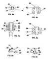
- FIG. 6 ais an enlarged axial cross-sectional view of the circled area of FIG. 5 showing a sliding nut.
- FIG. 6 bis an enlarged axial cross-section view of the circled area of FIG. 5 showing a dynamized spinal stabilization system with a clamping nut.
- FIG. 7 ais an enlarged view of FIG. 6 a.
- FIG. 7 bis an enlarged view of FIG. 6 b.
- FIG. 7 cis an enlarged view of FIG. 5 showing an upper saddle clamp.
- FIG. 8 ais an axial cross-sectional view of a stop lock clamp, taken along the line 8 — 8 of FIG. 3 .
- FIG. 8 bis an enlarged view of FIG. 8 a.
- FIG. 8 cis a view of FIG. 8 b showing an upper and lower stop lock saddle clamp
- FIG. 9 ais an isometric view of a plate guide with an optional boss.
- FIG. 9 bis an isometric view of the bottom of a plate guide showing two spikes.
- the best mode material for the stabilizeris titanium alloy Ti-6AI-4V. It is the most bio-compatable of all metals due to its total resistance to attack by human and animal body's. It also has high strength, low density, flexibility, low modulus of elasticity, and a low thermal coefficient of expansion. Other advantages of this material are its decreased interference with metal detectors and with magnetic resonance imaging (MRI) used for postoperative evaluation. Ti-6AI-4V is best in the alpha-beta phase, which can be heat-treated to obtain the desired properties. Details of the fabrication methods and dimensions of the model are given in the section titled Dynamized Bone Stabilizer Manufacturing Method.
- the Dynamized Spinal Stabilization System 10The Dynamized Spinal Stabilization System 10 .
- the Plate Guide 20Including The Guide Tubes 22 , And The Outrigger Arm 28 ,
- the Bone Screws 40Including The Bone Thread End 42 , The Drive Feature 44 , And The Machine Threaded Stud Portion 46 .
- Dynamizing And Rigidizing Actionincluding: The Sliding Nut 48 And The Clamp Nut 49 .
- the Graft 62The Graft 62 .
- the system 10is implanted on vertebra or individual bones 60 on the spinal or bone column 61 .
- the system 10includes a bone plate 30 having a longitudinal axis 31 substantially parallel to the spinal or bone column axis 63 , a plate guide 20 with two tubes 22 , an outrigger arm 38 , an anterior screw 47 , a bone screw 40 , two different nuts 48 and 49 , and a graft 62 .
- a stop lock clamp 50including an upper clamp 52 , a lower clamp 54 , and a stop screw 56 .
- the plate guide 20is an “L” shaped plate, the top face of the plate guide surface 21 interfaces the lower face of the plate 30 and the plate guide tube 22 outer diameter interfaces with the plate slot 34 sides.
- the interface surfacesare static.
- the deviceis free the interface is dynamic sliding. Sliding does not allow rotation or horizontal translation of the plate relative to the vertebrae or individual bones, This device will allow axial sliding of the bone screws 40 and plate guides 20 .
- the outrigger arm 28 of the plate guide 20comprises a contiguous metal piece curved 23 to fit the lateral or anterior curvature of the vertebral body 60 .
- the outrigger arm 28extends perpendicular to and substantially in the plane of the plate guide 20 anteriorly, for placement of an anterior bone screw 47 which is fixed to the plate guide through a locking means.
- the anterior bone screwserves to provide rotational, and pullout resistance to the plate guides.
- An additional two-hole plate guide 26shown in FIG. 3 allows the plate guide to be set at an angle with the plate 30 .
- the platemay have an integral boss 24 , with drilled holes in place of the tubes 22 , as shown in FIG. 9 a.
- the spikes 29shown in FIG. 9 b, are driven into the vertebra or individual bones stabilizing the outrigger arm 28 prior to or during bone screw placement.
- the plate 30has a rectangular cross section with a slot 34 creating two rails 35 , shown in the section view of FIG. 6 a.
- the plate end 32is semicircular with rounded ends and a width equal to that of the plate rail.
- the plate lower faceinterfaces with the plate guide's upper surface 21 .
- the plate upper faceinterfaces with the nut flange 57 .
- the platealso has two substantially parallel side faces with a thickness of sufficient strength to substantially eliminate bending.
- the plate 30is machined from a single piece of titanium. It has an through guide Slot 34 parallel to its longitudinal axis 31 to receive and contain the tube portion 22 of the plate guide 20 .
- this plateallows the bone screws 40 to be infinitely positioned axially to place the bone screws into the desired position of the vertebra or individual bones 60 .
- the platemay be bent 23 at the time of manufacture or at the time of surgery to accommodate spinal curvatures.
- the sliding nut 48clamps tight against the end of guide tube 22 allowing clearance 70 , shown in FIG. 7 a, between the plate 30 and the plate guide 20 .
- the guide tubes 22 diametersare smaller then the plate slot 34 width to maintain clearance between the plate slot and the tube. Installing sliding nuts 48 will allow the plate 30 to slide relative to the plate guide 20 .
- the clamping nut 49shown in FIG. 7 b, is undercut with a clearance 71 preventing the nut from clamping against the tube 22 .
- This clampingforces the plate 30 against the plate guide 20 clamping them together rigidly to preventing relative motion between the plate and the plate guide.
- Installing the clamp nut 49will prevent motion between the plate and the plate guide.
- sliding or rigiditycan be selected or changed by the specific nut, 48 or 49 . Because of the metal-to-metal clamping with either nut there is no need for additional nut locking devices.
- the stop lock clamp assembly 50is a clamp consisting of an upper clamp 52 , a lower clamp 54 , and a screw 56 that pulls the upper and lower clamps against the plate 30 .
- This rigid clampwill prevent or stop the plate guide 20 from distracting yet will allow it to freely subside, maintaining compression between the vertebra or individual bones 60 and the graft 62 to allow for any graft resorbtion and settling.
- the stop lock clampwill also increase plate rigidity and serve as a travel limit stop for the bone screw 40 /plate guide 20 assembly with respect to the plate 30 .
- the graftshould be compressed before tightening the lock clamp screw 56 .
- An optional upper stop lock saddle clamp 59 and a lower stop lock saddle clamp 58shown FIG. 8 c, will add rigidity to the system 10 and will prevent the plate slot from widening.
- Ti-AI6-V4The components are made of titanium alloy Ti-AI6-V4. They are machined from rod and bar stock. Ti-AI6-V4 can be machined by the customary methods. However it requires slow speeds, heavy feeds to reduce work hardening, and an ample supply of coolant. Because heavy feeds create large loads on the tool bits, the machine tools and setups must be very rigid to avoid chattering. The tool bits must remain sharp therefor carbide tool bits are recommended. Ti-AI6-V4 can be welded only in a clean inert atmosphere. The recommended welding process is TIG (Tungsten electrode Inert Gas).
- a recommended titanium supplieris Tico Titanium, inc.
- Tycocan furnish bar and rod stock or near net cut titanium shapes with excellent edge finish and a high degree of intricacy or size tolerance using abrasive water-jet cutting systems operated by CAD systems.
- Water-Jet cut titanium materialsare preferred because the cold cutting process does not change the properties of the material.
- the plateis 4.5 mm (0.187 inch) thick, 12.7 mm (0.500 inch) wide, and 108 mm (4.25 inch) long.
- the plate slotis 6.5 mm (0.255 inch) wide.
- the guide plateis 2.5 mm (0.100 inch) thick, 22.8 mm (0.900 inch) long, and 12.7 mm (0.500 inch) wide.
- the guide plate tubesare 6.3 mm (0.250 inch) outer diameter, 4.83 mm (0.190 inch) inner diameter, and 5 mm (0.200 inch) long.
- the outriggeris 2.5 mm (0.100 inch) thick, 5 mm (0.200 inch) wide, and 15 mm (0.600 inch) long.
- the bone screwis 22 mm (0.86 inch) long with:
- the plate 30is attached lateral to the vertebra or bone body 60 with the bone screws 40 through the sliding plate guides tubes 22 .
- the bone screws 40are threaded into the vertebra or individual bones 60 from a lateral exposure with bicortical purchase.
- the methodis described as a two level fusion involving three adjacent vertebra or individual bone segments with the discs replaced by interbody grafts 62 .
- the interbody graft 62is placed and spinal alignment is confirmed.
- Next posterior (posterior-lateral) bone screw 40 pilot holesare drilled through a template or drill guide that will ensure proper posterior bone screw 40 alignment, with the adjacent vertebra or individual bone segment's posterior bone screws. Proper posterior bone screw alignment will prevent the plate guide 20 from binding in the plate slot 34 .
- Bone screw 40 pilot hole drilling to direct bone screw placementis well known to those practiced in the art. The pilot holes are tapped with an internal thread and then the posterior screws are placed. Self-tapping bone screws do not require that the pilot hole be tapped.
- Two posterior bone screws 40are placed per vertebra or individual bone segments 60 .
- the plate guides 20are then placed over the posterior bone screws 40 at each segment. The posterior bone screws are adjusted by rotating the bone screw by the middle drive feature 44 or the top drive feature 45 to control the plate guide 20 height.
- the plate 30is loaded onto the plate guide tubes 22 .
- the plate guide tubesslidably engage the plate internal slot 34 .
- the plate 30is loaded onto the plate guide tubes 22 . Plate preloading results in maintenance of construct compression.
- Each sliding vertebra or individual bone segment's posterior bone screws 40are then secured firmly to the plate guide tubes 22 with a bone screw-sliding nut 48 .
- the loadingis carried out with a compression tool means followed by placement of a stop lock clamp 50 , or by subsequent expansion of an expandable interbody means. If needed the stop lock clamp is slid against the plate guide 20 during compression, and then the stop lock clamp is clamped in place, holding the construct in compression. Construct compression techniques and interbody device distraction are well known to those practiced in the art.
- the outrigger 28is then secured with the anterior bone screw 47 .
- Each segment screw to be rigidized with respect to the plate 30is clamped using the bone screw clamp nut 49 .
- the final adjustment of the plate guide heightsare made by loosening the two nuts on the plate guide to be adjusted, then rotating the bone screw with a driving wrench on the top drive feature until the plate guide is at the required level.
- the wrenchshould be held while the nuts are being retightened.
- clamp nuts 49are threaded onto bone screw machine threaded stud portion 46 and tightened. The clamp nuts clamp against the plate thereby restricting motion of the plate with the plate guide 20 .
Landscapes
- Health & Medical Sciences (AREA)
- Orthopedic Medicine & Surgery (AREA)
- Life Sciences & Earth Sciences (AREA)
- Neurology (AREA)
- Surgery (AREA)
- Heart & Thoracic Surgery (AREA)
- Engineering & Computer Science (AREA)
- Biomedical Technology (AREA)
- Nuclear Medicine, Radiotherapy & Molecular Imaging (AREA)
- Medical Informatics (AREA)
- Molecular Biology (AREA)
- Animal Behavior & Ethology (AREA)
- General Health & Medical Sciences (AREA)
- Public Health (AREA)
- Veterinary Medicine (AREA)
- Surgical Instruments (AREA)
- Prostheses (AREA)
Abstract
Description
Claims (7)
Priority Applications (1)
| Application Number | Priority Date | Filing Date | Title |
|---|---|---|---|
| US10/340,967US6682530B2 (en) | 2002-01-14 | 2003-01-13 | Dynamized vertebral stabilizer using an outrigger implant |
Applications Claiming Priority (2)
| Application Number | Priority Date | Filing Date | Title |
|---|---|---|---|
| US34818002P | 2002-01-14 | 2002-01-14 | |
| US10/340,967US6682530B2 (en) | 2002-01-14 | 2003-01-13 | Dynamized vertebral stabilizer using an outrigger implant |
Publications (2)
| Publication Number | Publication Date |
|---|---|
| US20030135210A1 US20030135210A1 (en) | 2003-07-17 |
| US6682530B2true US6682530B2 (en) | 2004-01-27 |
Family
ID=26992315
Family Applications (1)
| Application Number | Title | Priority Date | Filing Date |
|---|---|---|---|
| US10/340,967Expired - LifetimeUS6682530B2 (en) | 2002-01-14 | 2003-01-13 | Dynamized vertebral stabilizer using an outrigger implant |
Country Status (1)
| Country | Link |
|---|---|
| US (1) | US6682530B2 (en) |
Cited By (87)
| Publication number | Priority date | Publication date | Assignee | Title |
|---|---|---|---|---|
| US20040143264A1 (en)* | 2002-08-23 | 2004-07-22 | Mcafee Paul C. | Metal-backed UHMWPE rod sleeve system preserving spinal motion |
| US20040172020A1 (en)* | 2001-04-06 | 2004-09-02 | Jacques Beaurain | Spinal osteosynthesis device and preparation method |
| US20040254577A1 (en)* | 2001-10-18 | 2004-12-16 | Joel Delecrin | Progressive approach osteosynthesis device and preassembly method |
| US20050010215A1 (en)* | 2001-10-18 | 2005-01-13 | Joel Delecrin | Plate for osteosynthesis device and preassembling method |
| US20050049595A1 (en)* | 2003-09-03 | 2005-03-03 | Suh Sean S. | Track-plate carriage system |
| US20050107788A1 (en)* | 2001-12-12 | 2005-05-19 | Jacques Beaurain | Implant for osseous anchoring with polyaxial head |
| US20050234452A1 (en)* | 2004-04-16 | 2005-10-20 | Malandain Hugues F | Subcutaneous support |
| US20050234456A1 (en)* | 2004-04-16 | 2005-10-20 | Malandain Hugues F | Plate system for minimally invasive support of the spine |
| US20060111715A1 (en)* | 2004-02-27 | 2006-05-25 | Jackson Roger P | Dynamic stabilization assemblies, tool set and method |
| US20060111712A1 (en)* | 2004-11-23 | 2006-05-25 | Jackson Roger P | Spinal fixation tool set and method |
| US20060149252A1 (en)* | 2004-12-30 | 2006-07-06 | Markworth Aaron D | Bone anchorage screw with built-in hinged plate |
| US20060149237A1 (en)* | 2004-12-30 | 2006-07-06 | Markworth Aaron D | Screw with deployable interlaced dual rods |
| US20060200129A1 (en)* | 2005-02-18 | 2006-09-07 | Aldo Denti | Implants and methods for positioning same in surgical approaches to the spine |
| US20070055244A1 (en)* | 2004-02-27 | 2007-03-08 | Jackson Roger P | Dynamic fixation assemblies with inner core and outer coil-like member |
| US20070270860A1 (en)* | 2005-09-30 | 2007-11-22 | Jackson Roger P | Dynamic stabilization connecting member with slitted core and outer sleeve |
| US20070276502A1 (en)* | 2004-03-11 | 2007-11-29 | Craniotech Acr Devices, Llc | Mandibular Bone Transport Reconstruction Plate |
| US20070293862A1 (en)* | 2005-09-30 | 2007-12-20 | Jackson Roger P | Dynamic stabilization connecting member with elastic core and outer sleeve |
| US20070293864A1 (en)* | 2006-06-16 | 2007-12-20 | Reimels William J | Bone plate system providing dynamic compression |
| US20080091213A1 (en)* | 2004-02-27 | 2008-04-17 | Jackson Roger P | Tool system for dynamic spinal implants |
| US20080147122A1 (en)* | 2006-10-12 | 2008-06-19 | Jackson Roger P | Dynamic stabilization connecting member with molded inner segment and surrounding external elastomer |
| US20080177263A1 (en)* | 2006-10-24 | 2008-07-24 | Aesculap Implant Systems, Inc | Dynamic stabilization device for anterior lower lumbar vertebral fusion |
| US20080294194A1 (en)* | 2007-05-22 | 2008-11-27 | Marco Dagoberto Capote | Spinal stabilization systems and methods |
| US20080294198A1 (en)* | 2006-01-09 | 2008-11-27 | Jackson Roger P | Dynamic spinal stabilization assembly with torsion and shear control |
| US20080300633A1 (en)* | 2007-05-31 | 2008-12-04 | Jackson Roger P | Dynamic stabilization connecting member with pre-tensioned solid core |
| US20080319490A1 (en)* | 2005-09-30 | 2008-12-25 | Jackson Roger P | Polyaxial bone anchor assembly with one-piece closure, pressure insert and plastic elongate member |
| US20090043341A1 (en)* | 2007-08-09 | 2009-02-12 | Aesculap, Inc. | Dynamic extension plate for anterior cervical fusion and method of installation |
| US20090105820A1 (en)* | 2007-10-23 | 2009-04-23 | Jackson Roger P | Dynamic stabilization member with fin support and cable core extension |
| US20090105764A1 (en)* | 2007-10-23 | 2009-04-23 | Jackson Roger P | Dynamic stabilization member with fin support and solid core extension |
| US20090105832A1 (en)* | 2007-06-08 | 2009-04-23 | Ldr Medical | Intersomatic cage, intervertebral prosthesis, anchoring device and implantation instruments |
| US20090281574A1 (en)* | 2007-02-12 | 2009-11-12 | Jackson Roger P | Dynamic stabilization assembly with frusto-conical connection |
| US20090318969A1 (en)* | 2008-06-19 | 2009-12-24 | Wilfried Matthis | Bone anchoring assembly |
| US20100010543A1 (en)* | 2007-05-01 | 2010-01-14 | Jackson Roger P | Dynamic stabilization connecting member with floating core, compression spacer and over-mold |
| US7648520B2 (en) | 2004-04-16 | 2010-01-19 | Kyphon Sarl | Pedicle screw assembly |
| US7704271B2 (en) | 2005-12-19 | 2010-04-27 | Abdou M Samy | Devices and methods for inter-vertebral orthopedic device placement |
| US20100331887A1 (en)* | 2006-01-09 | 2010-12-30 | Jackson Roger P | Longitudinal connecting member with sleeved tensioned cords |
| US7901437B2 (en) | 2007-01-26 | 2011-03-08 | Jackson Roger P | Dynamic stabilization member with molded connection |
| US20110098755A1 (en)* | 2009-06-15 | 2011-04-28 | Jackson Roger P | Polyaxial bone anchor with non-pivotable retainer and pop-on shank, some with friction fit |
| WO2011056000A3 (en)* | 2009-11-06 | 2011-09-22 | 주식회사 위노바 | Intervertebral body fusion device |
| US8034081B2 (en) | 2007-02-06 | 2011-10-11 | CollabComl, LLC | Interspinous dynamic stabilization implant and method of implanting |
| US8092502B2 (en) | 2003-04-09 | 2012-01-10 | Jackson Roger P | Polyaxial bone screw with uploaded threaded shank and method of assembly and use |
| US8100915B2 (en) | 2004-02-27 | 2012-01-24 | Jackson Roger P | Orthopedic implant rod reduction tool set and method |
| US8303660B1 (en) | 2006-04-22 | 2012-11-06 | Samy Abdou | Inter-vertebral disc prosthesis with variable rotational stop and methods of use |
| US20130030473A1 (en)* | 2001-03-09 | 2013-01-31 | Co-Ligne Ag | Longitudinal implant |
| US8366745B2 (en) | 2007-05-01 | 2013-02-05 | Jackson Roger P | Dynamic stabilization assembly having pre-compressed spacers with differential displacements |
| US8444681B2 (en) | 2009-06-15 | 2013-05-21 | Roger P. Jackson | Polyaxial bone anchor with pop-on shank, friction fit retainer and winged insert |
| US8475498B2 (en) | 2007-01-18 | 2013-07-02 | Roger P. Jackson | Dynamic stabilization connecting member with cord connection |
| US8591515B2 (en) | 2004-11-23 | 2013-11-26 | Roger P. Jackson | Spinal fixation tool set and method |
| US8814913B2 (en) | 2002-09-06 | 2014-08-26 | Roger P Jackson | Helical guide and advancement flange with break-off extensions |
| US8845691B2 (en) | 2003-09-01 | 2014-09-30 | Ldr Medical | Osseous anchoring implant with a polyaxial head and method for installing the implant |
| US8845649B2 (en) | 2004-09-24 | 2014-09-30 | Roger P. Jackson | Spinal fixation tool set and method for rod reduction and fastener insertion |
| US8979904B2 (en) | 2007-05-01 | 2015-03-17 | Roger P Jackson | Connecting member with tensioned cord, low profile rigid sleeve and spacer with torsion control |
| US9050139B2 (en) | 2004-02-27 | 2015-06-09 | Roger P. Jackson | Orthopedic implant rod reduction tool set and method |
| US9216041B2 (en) | 2009-06-15 | 2015-12-22 | Roger P. Jackson | Spinal connecting members with tensioned cords and rigid sleeves for engaging compression inserts |
| US9216048B2 (en) | 2009-03-18 | 2015-12-22 | Integrated Spinal Concepts, Inc. | Image-guided minimal-step placement of screw into bone |
| US9408646B2 (en) | 2003-09-03 | 2016-08-09 | DePuy Synthes Products, Inc. | Bone plate with captive clips |
| US9414863B2 (en) | 2005-02-22 | 2016-08-16 | Roger P. Jackson | Polyaxial bone screw with spherical capture, compression insert and alignment and retention structures |
| US9451989B2 (en) | 2007-01-18 | 2016-09-27 | Roger P Jackson | Dynamic stabilization members with elastic and inelastic sections |
| US9468479B2 (en) | 2013-09-06 | 2016-10-18 | Cardinal Health 247, Inc. | Bone plate |
| US9480517B2 (en) | 2009-06-15 | 2016-11-01 | Roger P. Jackson | Polyaxial bone anchor with pop-on shank, shank, friction fit retainer, winged insert and low profile edge lock |
| US9615931B2 (en)* | 2015-03-20 | 2017-04-11 | Globus Medical, Inc. | Surgical plate systems |
| US9675389B2 (en) | 2009-12-07 | 2017-06-13 | Samy Abdou | Devices and methods for minimally invasive spinal stabilization and instrumentation |
| US9743957B2 (en) | 2004-11-10 | 2017-08-29 | Roger P. Jackson | Polyaxial bone screw with shank articulation pressure insert and method |
| US9962192B2 (en) | 2016-03-17 | 2018-05-08 | Medos International Sarl | Multipoint fixation implants |
| US9980753B2 (en) | 2009-06-15 | 2018-05-29 | Roger P Jackson | pivotal anchor with snap-in-place insert having rotation blocking extensions |
| US10039578B2 (en) | 2003-12-16 | 2018-08-07 | DePuy Synthes Products, Inc. | Methods and devices for minimally invasive spinal fixation element placement |
| US10194951B2 (en) | 2005-05-10 | 2019-02-05 | Roger P. Jackson | Polyaxial bone anchor with compound articulation and pop-on shank |
| US10258382B2 (en) | 2007-01-18 | 2019-04-16 | Roger P. Jackson | Rod-cord dynamic connection assemblies with slidable bone anchor attachment members along the cord |
| US10299839B2 (en) | 2003-12-16 | 2019-05-28 | Medos International Sárl | Percutaneous access devices and bone anchor assemblies |
| US10363070B2 (en) | 2009-06-15 | 2019-07-30 | Roger P. Jackson | Pivotal bone anchor assemblies with pressure inserts and snap on articulating retainers |
| US10383660B2 (en) | 2007-05-01 | 2019-08-20 | Roger P. Jackson | Soft stabilization assemblies with pretensioned cords |
| US10492912B2 (en) | 2017-08-18 | 2019-12-03 | Innovasis, Inc. | Interbody spinal fusion implant having locking elements with lateral displacement |
| US10548740B1 (en) | 2016-10-25 | 2020-02-04 | Samy Abdou | Devices and methods for vertebral bone realignment |
| US10555764B2 (en) | 2017-08-22 | 2020-02-11 | Innovasis, Inc. | Interbody spinal fusion implant having locking elements that outwardly displace for locking |
| US10575961B1 (en) | 2011-09-23 | 2020-03-03 | Samy Abdou | Spinal fixation devices and methods of use |
| US10695105B2 (en) | 2012-08-28 | 2020-06-30 | Samy Abdou | Spinal fixation devices and methods of use |
| US10729469B2 (en) | 2006-01-09 | 2020-08-04 | Roger P. Jackson | Flexible spinal stabilization assembly with spacer having off-axis core member |
| US10857003B1 (en) | 2015-10-14 | 2020-12-08 | Samy Abdou | Devices and methods for vertebral stabilization |
| US10898232B2 (en) | 2018-03-20 | 2021-01-26 | Medos International Sàrl | Multipoint fixation implants and related methods |
| US10918498B2 (en) | 2004-11-24 | 2021-02-16 | Samy Abdou | Devices and methods for inter-vertebral orthopedic device placement |
| US10973648B1 (en) | 2016-10-25 | 2021-04-13 | Samy Abdou | Devices and methods for vertebral bone realignment |
| US11006982B2 (en) | 2012-02-22 | 2021-05-18 | Samy Abdou | Spinous process fixation devices and methods of use |
| US11026802B2 (en) | 2003-04-21 | 2021-06-08 | Rsb Spine Llc | Bone plate stabilization system and method for its use |
| US11173040B2 (en) | 2012-10-22 | 2021-11-16 | Cogent Spine, LLC | Devices and methods for spinal stabilization and instrumentation |
| US11179248B2 (en) | 2018-10-02 | 2021-11-23 | Samy Abdou | Devices and methods for spinal implantation |
| US11304728B2 (en)* | 2020-02-14 | 2022-04-19 | Medos International Sarl | Integrated multipoint fixation screw |
| US11419642B2 (en) | 2003-12-16 | 2022-08-23 | Medos International Sarl | Percutaneous access devices and bone anchor assemblies |
| US11426210B2 (en) | 2019-09-25 | 2022-08-30 | Medos International Sàrl | Multipoint angled fixation implants for multiple screws and related methods |
Families Citing this family (28)
| Publication number | Priority date | Publication date | Assignee | Title |
|---|---|---|---|---|
| US7833250B2 (en) | 2004-11-10 | 2010-11-16 | Jackson Roger P | Polyaxial bone screw with helically wound capture connection |
| US8876868B2 (en) | 2002-09-06 | 2014-11-04 | Roger P. Jackson | Helical guide and advancement flange with radially loaded lip |
| US7377923B2 (en) | 2003-05-22 | 2008-05-27 | Alphatec Spine, Inc. | Variable angle spinal screw assembly |
| CA2529119A1 (en)* | 2003-06-17 | 2004-12-23 | Facet-Med Ltd. | Orthopedic clamps |
| US8366753B2 (en) | 2003-06-18 | 2013-02-05 | Jackson Roger P | Polyaxial bone screw assembly with fixed retaining structure |
| US7967850B2 (en) | 2003-06-18 | 2011-06-28 | Jackson Roger P | Polyaxial bone anchor with helical capture connection, insert and dual locking assembly |
| US8926670B2 (en) | 2003-06-18 | 2015-01-06 | Roger P. Jackson | Polyaxial bone screw assembly |
| US8926672B2 (en) | 2004-11-10 | 2015-01-06 | Roger P. Jackson | Splay control closure for open bone anchor |
| US9168069B2 (en) | 2009-06-15 | 2015-10-27 | Roger P. Jackson | Polyaxial bone anchor with pop-on shank and winged insert with lower skirt for engaging a friction fit retainer |
| WO2006057837A1 (en) | 2004-11-23 | 2006-06-01 | Jackson Roger P | Spinal fixation tool attachment structure |
| US20060229607A1 (en)* | 2005-03-16 | 2006-10-12 | Sdgi Holdings, Inc. | Systems, kits and methods for treatment of the spinal column using elongate support members |
| US8328853B2 (en)* | 2006-04-03 | 2012-12-11 | Ib Medical, Llc | Static compression device |
| US8257407B2 (en)* | 2008-04-23 | 2012-09-04 | Aryan Henry E | Bone plate system and method |
| US9668771B2 (en) | 2009-06-15 | 2017-06-06 | Roger P Jackson | Soft stabilization assemblies with off-set connector |
| US8998959B2 (en) | 2009-06-15 | 2015-04-07 | Roger P Jackson | Polyaxial bone anchors with pop-on shank, fully constrained friction fit retainer and lock and release insert |
| US11229457B2 (en) | 2009-06-15 | 2022-01-25 | Roger P. Jackson | Pivotal bone anchor assembly with insert tool deployment |
| US8491638B2 (en)* | 2009-12-11 | 2013-07-23 | Globus Medical, Inc. | Dynamic spine stabilizers |
| US8911479B2 (en) | 2012-01-10 | 2014-12-16 | Roger P. Jackson | Multi-start closures for open implants |
| US8911478B2 (en) | 2012-11-21 | 2014-12-16 | Roger P. Jackson | Splay control closure for open bone anchor |
| US9107767B2 (en)* | 2013-01-16 | 2015-08-18 | DePuy Synthes Products, Inc. | Intervertebral cage with anterior fixation and stabilization |
| US10058354B2 (en) | 2013-01-28 | 2018-08-28 | Roger P. Jackson | Pivotal bone anchor assembly with frictional shank head seating surfaces |
| US8852239B2 (en) | 2013-02-15 | 2014-10-07 | Roger P Jackson | Sagittal angle screw with integral shank and receiver |
| US9566092B2 (en) | 2013-10-29 | 2017-02-14 | Roger P. Jackson | Cervical bone anchor with collet retainer and outer locking sleeve |
| US9717533B2 (en) | 2013-12-12 | 2017-08-01 | Roger P. Jackson | Bone anchor closure pivot-splay control flange form guide and advancement structure |
| US9451993B2 (en) | 2014-01-09 | 2016-09-27 | Roger P. Jackson | Bi-radial pop-on cervical bone anchor |
| US10064658B2 (en) | 2014-06-04 | 2018-09-04 | Roger P. Jackson | Polyaxial bone anchor with insert guides |
| US9597119B2 (en) | 2014-06-04 | 2017-03-21 | Roger P. Jackson | Polyaxial bone anchor with polymer sleeve |
| CN104274232A (en)* | 2014-09-02 | 2015-01-14 | 苏州瑞华医院有限公司 | Single-rail type sliding bonesetting device for treating femoral shaft fracture |
Citations (5)
| Publication number | Priority date | Publication date | Assignee | Title |
|---|---|---|---|---|
| US4790297A (en)* | 1987-07-24 | 1988-12-13 | Biotechnology, Inc. | Spinal fixation method and system |
| US5290288A (en)* | 1990-02-08 | 1994-03-01 | Vignaud Jean Louis | Multi-function device for the osteosynthesis of rachis |
| US6176861B1 (en)* | 1994-10-25 | 2001-01-23 | Sdgi Holdings, Inc. | Modular spinal system |
| US20020029040A1 (en)* | 1999-04-16 | 2002-03-07 | Morrison Matthew M. | Multi-axial bone anchor system |
| US20030045875A1 (en)* | 2001-09-04 | 2003-03-06 | Bertranou Patrick P. | Spinal assembly plate |
- 2003
- 2003-01-13USUS10/340,967patent/US6682530B2/ennot_activeExpired - Lifetime
Patent Citations (5)
| Publication number | Priority date | Publication date | Assignee | Title |
|---|---|---|---|---|
| US4790297A (en)* | 1987-07-24 | 1988-12-13 | Biotechnology, Inc. | Spinal fixation method and system |
| US5290288A (en)* | 1990-02-08 | 1994-03-01 | Vignaud Jean Louis | Multi-function device for the osteosynthesis of rachis |
| US6176861B1 (en)* | 1994-10-25 | 2001-01-23 | Sdgi Holdings, Inc. | Modular spinal system |
| US20020029040A1 (en)* | 1999-04-16 | 2002-03-07 | Morrison Matthew M. | Multi-axial bone anchor system |
| US20030045875A1 (en)* | 2001-09-04 | 2003-03-06 | Bertranou Patrick P. | Spinal assembly plate |
Cited By (182)
| Publication number | Priority date | Publication date | Assignee | Title |
|---|---|---|---|---|
| US8784454B2 (en)* | 2001-03-09 | 2014-07-22 | Co-Ligne Ag | Longitudinal implant |
| US20130030473A1 (en)* | 2001-03-09 | 2013-01-31 | Co-Ligne Ag | Longitudinal implant |
| US20040172020A1 (en)* | 2001-04-06 | 2004-09-02 | Jacques Beaurain | Spinal osteosynthesis device and preparation method |
| US7507248B2 (en) | 2001-04-06 | 2009-03-24 | Ldr Medical | Spinal osteosynthesis device and preparation method |
| US8162988B2 (en)* | 2001-10-18 | 2012-04-24 | Ldr Medical | Plate for osteosynthesis device and method of preassembling such device |
| US20040254577A1 (en)* | 2001-10-18 | 2004-12-16 | Joel Delecrin | Progressive approach osteosynthesis device and preassembly method |
| US20050010215A1 (en)* | 2001-10-18 | 2005-01-13 | Joel Delecrin | Plate for osteosynthesis device and preassembling method |
| US8221457B2 (en) | 2001-10-18 | 2012-07-17 | Ldr Medical | Progressive approach osteosynthesis device and preassembly method |
| US9326795B2 (en) | 2001-12-12 | 2016-05-03 | Ldr Medical | Implant for osseous anchoring with polyaxial head |
| US20050107788A1 (en)* | 2001-12-12 | 2005-05-19 | Jacques Beaurain | Implant for osseous anchoring with polyaxial head |
| US20040143264A1 (en)* | 2002-08-23 | 2004-07-22 | Mcafee Paul C. | Metal-backed UHMWPE rod sleeve system preserving spinal motion |
| US8814913B2 (en) | 2002-09-06 | 2014-08-26 | Roger P Jackson | Helical guide and advancement flange with break-off extensions |
| US8540753B2 (en) | 2003-04-09 | 2013-09-24 | Roger P. Jackson | Polyaxial bone screw with uploaded threaded shank and method of assembly and use |
| US10952777B2 (en) | 2003-04-09 | 2021-03-23 | Roger P. Jackson | Pivotal bone screw assembly with receiver having threaded open channel and lower opening |
| US8092502B2 (en) | 2003-04-09 | 2012-01-10 | Jackson Roger P | Polyaxial bone screw with uploaded threaded shank and method of assembly and use |
| US11026802B2 (en) | 2003-04-21 | 2021-06-08 | Rsb Spine Llc | Bone plate stabilization system and method for its use |
| US8845691B2 (en) | 2003-09-01 | 2014-09-30 | Ldr Medical | Osseous anchoring implant with a polyaxial head and method for installing the implant |
| US9408646B2 (en) | 2003-09-03 | 2016-08-09 | DePuy Synthes Products, Inc. | Bone plate with captive clips |
| US9414870B2 (en) | 2003-09-03 | 2016-08-16 | DePuy Synthes Products, Inc. | Translatable carriage fixation system |
| US10368927B2 (en) | 2003-09-03 | 2019-08-06 | DePuy Synthes Products, Inc. | Bone plate with captive clips |
| US7666185B2 (en) | 2003-09-03 | 2010-02-23 | Synthes Usa, Llc | Translatable carriage fixation system |
| US8262659B2 (en) | 2003-09-03 | 2012-09-11 | Synthes Usa, Llc | Translatable carriage fixation system |
| US20060079901A1 (en)* | 2003-09-03 | 2006-04-13 | Ryan Christopher J | Translatable carriage fixation system |
| US20050049595A1 (en)* | 2003-09-03 | 2005-03-03 | Suh Sean S. | Track-plate carriage system |
| US11426216B2 (en) | 2003-12-16 | 2022-08-30 | DePuy Synthes Products, Inc. | Methods and devices for minimally invasive spinal fixation element placement |
| US11419642B2 (en) | 2003-12-16 | 2022-08-23 | Medos International Sarl | Percutaneous access devices and bone anchor assemblies |
| US10039578B2 (en) | 2003-12-16 | 2018-08-07 | DePuy Synthes Products, Inc. | Methods and devices for minimally invasive spinal fixation element placement |
| US10299839B2 (en) | 2003-12-16 | 2019-05-28 | Medos International Sárl | Percutaneous access devices and bone anchor assemblies |
| US8162948B2 (en) | 2004-02-27 | 2012-04-24 | Jackson Roger P | Orthopedic implant rod reduction tool set and method |
| US8900272B2 (en) | 2004-02-27 | 2014-12-02 | Roger P Jackson | Dynamic fixation assemblies with inner core and outer coil-like member |
| US20060111715A1 (en)* | 2004-02-27 | 2006-05-25 | Jackson Roger P | Dynamic stabilization assemblies, tool set and method |
| US8394133B2 (en) | 2004-02-27 | 2013-03-12 | Roger P. Jackson | Dynamic fixation assemblies with inner core and outer coil-like member |
| US8377067B2 (en) | 2004-02-27 | 2013-02-19 | Roger P. Jackson | Orthopedic implant rod reduction tool set and method |
| US8894657B2 (en) | 2004-02-27 | 2014-11-25 | Roger P. Jackson | Tool system for dynamic spinal implants |
| US8292892B2 (en) | 2004-02-27 | 2012-10-23 | Jackson Roger P | Orthopedic implant rod reduction tool set and method |
| US9050139B2 (en) | 2004-02-27 | 2015-06-09 | Roger P. Jackson | Orthopedic implant rod reduction tool set and method |
| US9055978B2 (en) | 2004-02-27 | 2015-06-16 | Roger P. Jackson | Orthopedic implant rod reduction tool set and method |
| US20070055244A1 (en)* | 2004-02-27 | 2007-03-08 | Jackson Roger P | Dynamic fixation assemblies with inner core and outer coil-like member |
| US8100915B2 (en) | 2004-02-27 | 2012-01-24 | Jackson Roger P | Orthopedic implant rod reduction tool set and method |
| US9216039B2 (en) | 2004-02-27 | 2015-12-22 | Roger P. Jackson | Dynamic spinal stabilization assemblies, tool set and method |
| US8066739B2 (en) | 2004-02-27 | 2011-11-29 | Jackson Roger P | Tool system for dynamic spinal implants |
| US7766915B2 (en) | 2004-02-27 | 2010-08-03 | Jackson Roger P | Dynamic fixation assemblies with inner core and outer coil-like member |
| US20110077692A1 (en)* | 2004-02-27 | 2011-03-31 | Jackson Roger P | Dynamic spinal stabilization assemblies, tool set and method |
| US7862587B2 (en) | 2004-02-27 | 2011-01-04 | Jackson Roger P | Dynamic stabilization assemblies, tool set and method |
| US20080091213A1 (en)* | 2004-02-27 | 2008-04-17 | Jackson Roger P | Tool system for dynamic spinal implants |
| US20100312287A1 (en)* | 2004-02-27 | 2010-12-09 | Jackson Roger P | Dynamic fixation assemblies with inner core and outer coil-like member |
| US9918751B2 (en) | 2004-02-27 | 2018-03-20 | Roger P. Jackson | Tool system for dynamic spinal implants |
| US7998216B2 (en)* | 2004-03-11 | 2011-08-16 | Craniotech Acr Devices, Llc | Mandibular bone transport reconstruction plate |
| US20070276502A1 (en)* | 2004-03-11 | 2007-11-29 | Craniotech Acr Devices, Llc | Mandibular Bone Transport Reconstruction Plate |
| US20100076494A1 (en)* | 2004-04-16 | 2010-03-25 | Kyphon Sarl | Pedicle screw assembly |
| US20050234452A1 (en)* | 2004-04-16 | 2005-10-20 | Malandain Hugues F | Subcutaneous support |
| US20050234456A1 (en)* | 2004-04-16 | 2005-10-20 | Malandain Hugues F | Plate system for minimally invasive support of the spine |
| US7524323B2 (en)* | 2004-04-16 | 2009-04-28 | Kyphon Sarl | Subcutaneous support |
| US7618418B2 (en) | 2004-04-16 | 2009-11-17 | Kyphon Sarl | Plate system for minimally invasive support of the spine |
| US7648520B2 (en) | 2004-04-16 | 2010-01-19 | Kyphon Sarl | Pedicle screw assembly |
| US8845649B2 (en) | 2004-09-24 | 2014-09-30 | Roger P. Jackson | Spinal fixation tool set and method for rod reduction and fastener insertion |
| US9743957B2 (en) | 2004-11-10 | 2017-08-29 | Roger P. Jackson | Polyaxial bone screw with shank articulation pressure insert and method |
| US10039577B2 (en) | 2004-11-23 | 2018-08-07 | Roger P Jackson | Bone anchor receiver with horizontal radiused tool attachment structures and parallel planar outer surfaces |
| US8273089B2 (en) | 2004-11-23 | 2012-09-25 | Jackson Roger P | Spinal fixation tool set and method |
| US9629669B2 (en) | 2004-11-23 | 2017-04-25 | Roger P. Jackson | Spinal fixation tool set and method |
| US11389214B2 (en) | 2004-11-23 | 2022-07-19 | Roger P. Jackson | Spinal fixation tool set and method |
| US9211150B2 (en) | 2004-11-23 | 2015-12-15 | Roger P. Jackson | Spinal fixation tool set and method |
| US8152810B2 (en) | 2004-11-23 | 2012-04-10 | Jackson Roger P | Spinal fixation tool set and method |
| US8591515B2 (en) | 2004-11-23 | 2013-11-26 | Roger P. Jackson | Spinal fixation tool set and method |
| US20060111712A1 (en)* | 2004-11-23 | 2006-05-25 | Jackson Roger P | Spinal fixation tool set and method |
| US11992423B2 (en) | 2004-11-24 | 2024-05-28 | Samy Abdou | Devices and methods for inter-vertebral orthopedic device placement |
| US11096799B2 (en) | 2004-11-24 | 2021-08-24 | Samy Abdou | Devices and methods for inter-vertebral orthopedic device placement |
| US10918498B2 (en) | 2004-11-24 | 2021-02-16 | Samy Abdou | Devices and methods for inter-vertebral orthopedic device placement |
| US7811311B2 (en) | 2004-12-30 | 2010-10-12 | Warsaw Orthopedic, Inc. | Screw with deployable interlaced dual rods |
| US20060149237A1 (en)* | 2004-12-30 | 2006-07-06 | Markworth Aaron D | Screw with deployable interlaced dual rods |
| US7789899B2 (en) | 2004-12-30 | 2010-09-07 | Warsaw Orthopedic, Inc. | Bone anchorage screw with built-in hinged plate |
| US20060149252A1 (en)* | 2004-12-30 | 2006-07-06 | Markworth Aaron D | Bone anchorage screw with built-in hinged plate |
| US20060200129A1 (en)* | 2005-02-18 | 2006-09-07 | Aldo Denti | Implants and methods for positioning same in surgical approaches to the spine |
| US7559929B2 (en) | 2005-02-18 | 2009-07-14 | Warsaw Orthopedic, Inc. | Implants and methods for positioning same in surgical approaches to the spine |
| USRE47551E1 (en) | 2005-02-22 | 2019-08-06 | Roger P. Jackson | Polyaxial bone screw with spherical capture, compression insert and alignment and retention structures |
| US9414863B2 (en) | 2005-02-22 | 2016-08-16 | Roger P. Jackson | Polyaxial bone screw with spherical capture, compression insert and alignment and retention structures |
| US10194951B2 (en) | 2005-05-10 | 2019-02-05 | Roger P. Jackson | Polyaxial bone anchor with compound articulation and pop-on shank |
| US20070293862A1 (en)* | 2005-09-30 | 2007-12-20 | Jackson Roger P | Dynamic stabilization connecting member with elastic core and outer sleeve |
| US8353932B2 (en) | 2005-09-30 | 2013-01-15 | Jackson Roger P | Polyaxial bone anchor assembly with one-piece closure, pressure insert and plastic elongate member |
| US8105368B2 (en) | 2005-09-30 | 2012-01-31 | Jackson Roger P | Dynamic stabilization connecting member with slitted core and outer sleeve |
| US20080319490A1 (en)* | 2005-09-30 | 2008-12-25 | Jackson Roger P | Polyaxial bone anchor assembly with one-piece closure, pressure insert and plastic elongate member |
| US20070270860A1 (en)* | 2005-09-30 | 2007-11-22 | Jackson Roger P | Dynamic stabilization connecting member with slitted core and outer sleeve |
| US8696711B2 (en) | 2005-09-30 | 2014-04-15 | Roger P. Jackson | Polyaxial bone anchor assembly with one-piece closure, pressure insert and plastic elongate member |
| US8292926B2 (en) | 2005-09-30 | 2012-10-23 | Jackson Roger P | Dynamic stabilization connecting member with elastic core and outer sleeve |
| US8613760B2 (en) | 2005-09-30 | 2013-12-24 | Roger P. Jackson | Dynamic stabilization connecting member with slitted core and outer sleeve |
| US8591560B2 (en) | 2005-09-30 | 2013-11-26 | Roger P. Jackson | Dynamic stabilization connecting member with elastic core and outer sleeve |
| US20100268281A1 (en)* | 2005-12-19 | 2010-10-21 | Abdou M Samy | Devices and methods for inter-vertebral orthopedic device placement |
| US8545538B2 (en)* | 2005-12-19 | 2013-10-01 | M. Samy Abdou | Devices and methods for inter-vertebral orthopedic device placement |
| US7704271B2 (en) | 2005-12-19 | 2010-04-27 | Abdou M Samy | Devices and methods for inter-vertebral orthopedic device placement |
| US20080294198A1 (en)* | 2006-01-09 | 2008-11-27 | Jackson Roger P | Dynamic spinal stabilization assembly with torsion and shear control |
| US10729469B2 (en) | 2006-01-09 | 2020-08-04 | Roger P. Jackson | Flexible spinal stabilization assembly with spacer having off-axis core member |
| US20100331887A1 (en)* | 2006-01-09 | 2010-12-30 | Jackson Roger P | Longitudinal connecting member with sleeved tensioned cords |
| US8303660B1 (en) | 2006-04-22 | 2012-11-06 | Samy Abdou | Inter-vertebral disc prosthesis with variable rotational stop and methods of use |
| US8083781B2 (en)* | 2006-06-16 | 2011-12-27 | Reimels William J | Bone plate system providing dynamic compression |
| US20070293864A1 (en)* | 2006-06-16 | 2007-12-20 | Reimels William J | Bone plate system providing dynamic compression |
| US20080147122A1 (en)* | 2006-10-12 | 2008-06-19 | Jackson Roger P | Dynamic stabilization connecting member with molded inner segment and surrounding external elastomer |
| US8262710B2 (en) | 2006-10-24 | 2012-09-11 | Aesculap Implant Systems, Llc | Dynamic stabilization device for anterior lower lumbar vertebral fusion |
| US20080177263A1 (en)* | 2006-10-24 | 2008-07-24 | Aesculap Implant Systems, Inc | Dynamic stabilization device for anterior lower lumbar vertebral fusion |
| US10470801B2 (en) | 2007-01-18 | 2019-11-12 | Roger P. Jackson | Dynamic spinal stabilization with rod-cord longitudinal connecting members |
| US10258382B2 (en) | 2007-01-18 | 2019-04-16 | Roger P. Jackson | Rod-cord dynamic connection assemblies with slidable bone anchor attachment members along the cord |
| US9451989B2 (en) | 2007-01-18 | 2016-09-27 | Roger P Jackson | Dynamic stabilization members with elastic and inelastic sections |
| US8475498B2 (en) | 2007-01-18 | 2013-07-02 | Roger P. Jackson | Dynamic stabilization connecting member with cord connection |
| US7901437B2 (en) | 2007-01-26 | 2011-03-08 | Jackson Roger P | Dynamic stabilization member with molded connection |
| US9101404B2 (en) | 2007-01-26 | 2015-08-11 | Roger P. Jackson | Dynamic stabilization connecting member with molded connection |
| US8034081B2 (en) | 2007-02-06 | 2011-10-11 | CollabComl, LLC | Interspinous dynamic stabilization implant and method of implanting |
| US20090281574A1 (en)* | 2007-02-12 | 2009-11-12 | Jackson Roger P | Dynamic stabilization assembly with frusto-conical connection |
| US8012177B2 (en) | 2007-02-12 | 2011-09-06 | Jackson Roger P | Dynamic stabilization assembly with frusto-conical connection |
| US8506599B2 (en) | 2007-02-12 | 2013-08-13 | Roger P. Jackson | Dynamic stabilization assembly with frusto-conical connection |
| US10383660B2 (en) | 2007-05-01 | 2019-08-20 | Roger P. Jackson | Soft stabilization assemblies with pretensioned cords |
| US8979904B2 (en) | 2007-05-01 | 2015-03-17 | Roger P Jackson | Connecting member with tensioned cord, low profile rigid sleeve and spacer with torsion control |
| US8366745B2 (en) | 2007-05-01 | 2013-02-05 | Jackson Roger P | Dynamic stabilization assembly having pre-compressed spacers with differential displacements |
| US8092500B2 (en) | 2007-05-01 | 2012-01-10 | Jackson Roger P | Dynamic stabilization connecting member with floating core, compression spacer and over-mold |
| US20100010543A1 (en)* | 2007-05-01 | 2010-01-14 | Jackson Roger P | Dynamic stabilization connecting member with floating core, compression spacer and over-mold |
| US20080294194A1 (en)* | 2007-05-22 | 2008-11-27 | Marco Dagoberto Capote | Spinal stabilization systems and methods |
| US8353937B2 (en) | 2007-05-22 | 2013-01-15 | Warsaw Orthopedic, Inc. | Spinal stabilization systems and methods |
| US20080300633A1 (en)* | 2007-05-31 | 2008-12-04 | Jackson Roger P | Dynamic stabilization connecting member with pre-tensioned solid core |
| US7951170B2 (en) | 2007-05-31 | 2011-05-31 | Jackson Roger P | Dynamic stabilization connecting member with pre-tensioned solid core |
| US20090105832A1 (en)* | 2007-06-08 | 2009-04-23 | Ldr Medical | Intersomatic cage, intervertebral prosthesis, anchoring device and implantation instruments |
| US8343219B2 (en) | 2007-06-08 | 2013-01-01 | Ldr Medical | Intersomatic cage, intervertebral prosthesis, anchoring device and implantation instruments |
| US10751187B2 (en) | 2007-06-08 | 2020-08-25 | Ldr Medical | Intersomatic cage, intervertebral prosthesis, anchoring device and implantation instruments |
| US20090043341A1 (en)* | 2007-08-09 | 2009-02-12 | Aesculap, Inc. | Dynamic extension plate for anterior cervical fusion and method of installation |
| US20090105764A1 (en)* | 2007-10-23 | 2009-04-23 | Jackson Roger P | Dynamic stabilization member with fin support and solid core extension |
| US8911477B2 (en) | 2007-10-23 | 2014-12-16 | Roger P. Jackson | Dynamic stabilization member with end plate support and cable core extension |
| US20090105820A1 (en)* | 2007-10-23 | 2009-04-23 | Jackson Roger P | Dynamic stabilization member with fin support and cable core extension |
| US9144437B2 (en)* | 2008-06-19 | 2015-09-29 | Biedermann Technologies Gmbh & Co. Kg | Bone anchoring assembly |
| US20090318969A1 (en)* | 2008-06-19 | 2009-12-24 | Wilfried Matthis | Bone anchoring assembly |
| US9907574B2 (en) | 2008-08-01 | 2018-03-06 | Roger P. Jackson | Polyaxial bone anchors with pop-on shank, friction fit fully restrained retainer, insert and tool receiving features |
| US11471220B2 (en) | 2009-03-18 | 2022-10-18 | Integrated Spinal Concepts, Inc. | Image-guided minimal-step placement of screw into bone |
| US10603116B2 (en) | 2009-03-18 | 2020-03-31 | Integrated Spinal Concepts, Inc. | Image-guided minimal-step placement of screw into bone |
| US9216048B2 (en) | 2009-03-18 | 2015-12-22 | Integrated Spinal Concepts, Inc. | Image-guided minimal-step placement of screw into bone |
| US9687306B2 (en) | 2009-03-18 | 2017-06-27 | Integrated Spinal Concepts, Inc. | Image-guided minimal-step placement of screw into bone |
| US9480517B2 (en) | 2009-06-15 | 2016-11-01 | Roger P. Jackson | Polyaxial bone anchor with pop-on shank, shank, friction fit retainer, winged insert and low profile edge lock |
| US20110098755A1 (en)* | 2009-06-15 | 2011-04-28 | Jackson Roger P | Polyaxial bone anchor with non-pivotable retainer and pop-on shank, some with friction fit |
| US10363070B2 (en) | 2009-06-15 | 2019-07-30 | Roger P. Jackson | Pivotal bone anchor assemblies with pressure inserts and snap on articulating retainers |
| US8556938B2 (en) | 2009-06-15 | 2013-10-15 | Roger P. Jackson | Polyaxial bone anchor with non-pivotable retainer and pop-on shank, some with friction fit |
| US9918745B2 (en) | 2009-06-15 | 2018-03-20 | Roger P. Jackson | Polyaxial bone anchor with pop-on shank and winged insert with friction fit compressive collet |
| US9216041B2 (en) | 2009-06-15 | 2015-12-22 | Roger P. Jackson | Spinal connecting members with tensioned cords and rigid sleeves for engaging compression inserts |
| US9980753B2 (en) | 2009-06-15 | 2018-05-29 | Roger P Jackson | pivotal anchor with snap-in-place insert having rotation blocking extensions |
| US8444681B2 (en) | 2009-06-15 | 2013-05-21 | Roger P. Jackson | Polyaxial bone anchor with pop-on shank, friction fit retainer and winged insert |
| WO2011056000A3 (en)* | 2009-11-06 | 2011-09-22 | 주식회사 위노바 | Intervertebral body fusion device |
| KR101144005B1 (en) | 2009-11-06 | 2012-05-09 | 주식회사 위노바 | Artificial Disk for Survical Interbody Fusion |
| US10543107B2 (en) | 2009-12-07 | 2020-01-28 | Samy Abdou | Devices and methods for minimally invasive spinal stabilization and instrumentation |
| US11918486B2 (en) | 2009-12-07 | 2024-03-05 | Samy Abdou | Devices and methods for minimally invasive spinal stabilization and instrumentation |
| US10857004B2 (en) | 2009-12-07 | 2020-12-08 | Samy Abdou | Devices and methods for minimally invasive spinal stabilization and instrumentation |
| US9675389B2 (en) | 2009-12-07 | 2017-06-13 | Samy Abdou | Devices and methods for minimally invasive spinal stabilization and instrumentation |
| US10610380B2 (en) | 2009-12-07 | 2020-04-07 | Samy Abdou | Devices and methods for minimally invasive spinal stabilization and instrumentation |
| US10945861B2 (en) | 2009-12-07 | 2021-03-16 | Samy Abdou | Devices and methods for minimally invasive spinal stabilization and instrumentation |
| US11324608B2 (en) | 2011-09-23 | 2022-05-10 | Samy Abdou | Spinal fixation devices and methods of use |
| US12167973B2 (en) | 2011-09-23 | 2024-12-17 | Samy Abdou | Spinal fixation devices and methods of use |
| US11517449B2 (en) | 2011-09-23 | 2022-12-06 | Samy Abdou | Spinal fixation devices and methods of use |
| US10575961B1 (en) | 2011-09-23 | 2020-03-03 | Samy Abdou | Spinal fixation devices and methods of use |
| US11006982B2 (en) | 2012-02-22 | 2021-05-18 | Samy Abdou | Spinous process fixation devices and methods of use |
| US11839413B2 (en) | 2012-02-22 | 2023-12-12 | Samy Abdou | Spinous process fixation devices and methods of use |
| US10695105B2 (en) | 2012-08-28 | 2020-06-30 | Samy Abdou | Spinal fixation devices and methods of use |
| US11559336B2 (en) | 2012-08-28 | 2023-01-24 | Samy Abdou | Spinal fixation devices and methods of use |
| US11918483B2 (en) | 2012-10-22 | 2024-03-05 | Cogent Spine Llc | Devices and methods for spinal stabilization and instrumentation |
| US11173040B2 (en) | 2012-10-22 | 2021-11-16 | Cogent Spine, LLC | Devices and methods for spinal stabilization and instrumentation |
| US9468479B2 (en) | 2013-09-06 | 2016-10-18 | Cardinal Health 247, Inc. | Bone plate |
| US9615931B2 (en)* | 2015-03-20 | 2017-04-11 | Globus Medical, Inc. | Surgical plate systems |
| US11246718B2 (en) | 2015-10-14 | 2022-02-15 | Samy Abdou | Devices and methods for vertebral stabilization |
| US10857003B1 (en) | 2015-10-14 | 2020-12-08 | Samy Abdou | Devices and methods for vertebral stabilization |
| US10779861B2 (en) | 2016-03-17 | 2020-09-22 | Medos International Sarl | Multipoint fixation implants |
| US12376888B2 (en) | 2016-03-17 | 2025-08-05 | Medos International Sàrl | Multipoint fixation implants |
| US11154332B2 (en) | 2016-03-17 | 2021-10-26 | Medos International Sarl | Multipoint fixation implants |
| US11974784B2 (en) | 2016-03-17 | 2024-05-07 | Medos International Sàrl | Multipoint fixation implants |
| US9962192B2 (en) | 2016-03-17 | 2018-05-08 | Medos International Sarl | Multipoint fixation implants |
| US11058548B1 (en) | 2016-10-25 | 2021-07-13 | Samy Abdou | Devices and methods for vertebral bone realignment |
| US10744000B1 (en) | 2016-10-25 | 2020-08-18 | Samy Abdou | Devices and methods for vertebral bone realignment |
| US11259935B1 (en) | 2016-10-25 | 2022-03-01 | Samy Abdou | Devices and methods for vertebral bone realignment |
| US11752008B1 (en) | 2016-10-25 | 2023-09-12 | Samy Abdou | Devices and methods for vertebral bone realignment |
| US10973648B1 (en) | 2016-10-25 | 2021-04-13 | Samy Abdou | Devices and methods for vertebral bone realignment |
| US10548740B1 (en) | 2016-10-25 | 2020-02-04 | Samy Abdou | Devices and methods for vertebral bone realignment |
| US10492912B2 (en) | 2017-08-18 | 2019-12-03 | Innovasis, Inc. | Interbody spinal fusion implant having locking elements with lateral displacement |
| US10555764B2 (en) | 2017-08-22 | 2020-02-11 | Innovasis, Inc. | Interbody spinal fusion implant having locking elements that outwardly displace for locking |
| US11717327B2 (en) | 2018-03-20 | 2023-08-08 | Medos International Sarl | Multipoint fixation implants and related methods |
| US10898232B2 (en) | 2018-03-20 | 2021-01-26 | Medos International Sàrl | Multipoint fixation implants and related methods |
| US12256962B2 (en) | 2018-03-20 | 2025-03-25 | Medos International Srl | Multipoint fixation implants and related methods |
| US11179248B2 (en) | 2018-10-02 | 2021-11-23 | Samy Abdou | Devices and methods for spinal implantation |
| US11998248B2 (en) | 2019-09-25 | 2024-06-04 | Medos International Sårl | Multipoint angled fixation implants for multiple screws and related methods |
| US11426210B2 (en) | 2019-09-25 | 2022-08-30 | Medos International Sàrl | Multipoint angled fixation implants for multiple screws and related methods |
| US12185980B2 (en) | 2020-02-14 | 2025-01-07 | Medos International Sàrl | Integrated multipoint fixation screw |
| US11304728B2 (en)* | 2020-02-14 | 2022-04-19 | Medos International Sarl | Integrated multipoint fixation screw |
Also Published As
| Publication number | Publication date |
|---|---|
| US20030135210A1 (en) | 2003-07-17 |
Similar Documents
| Publication | Publication Date | Title |
|---|---|---|
| US6682530B2 (en) | Dynamized vertebral stabilizer using an outrigger implant | |
| US5382248A (en) | System and method for stabilizing bone segments | |
| US6645207B2 (en) | Method and apparatus for dynamized spinal stabilization | |
| US8070784B2 (en) | Plating system for stabilizing a bony segment | |
| US4369769A (en) | Spinal fixation device and method | |
| CN100450455C (en) | Posterior pedicle screw and plate system and methods | |
| AU2008201340B2 (en) | Anterior cervical plate system having vertebral body engaging anchors, connecting plate, and method for installation thereof | |
| AU2004266737B2 (en) | Multi-axial orthopedic device and system, e.g. for spinal surgery | |
| AU2001247388B2 (en) | Multi-axial bone anchor system | |
| US5360431A (en) | Transpedicular screw system and method of use | |
| US7198627B2 (en) | Spinal fixation device and method | |
| US5129899A (en) | Bone fixation apparatus | |
| US8551144B2 (en) | Bone plate system configurable as static or dynamic implant | |
| US6613051B1 (en) | Anterior transpedicular fixation system and method for maintaining a vertebral column | |
| US20190201211A1 (en) | Systems and Methods for Treating Spinal Deformities | |
| US20060241593A1 (en) | Multi-piece vertebral attachment device | |
| US20100082067A1 (en) | System and method to stablize a spinal column including a spinolaminar locking plate | |
| US20020120271A1 (en) | Method and device for using extended interference fit screw shanks for spinal stabilization | |
| AU2008230056A1 (en) | Slidable bone plate system | |
| EP0746255A1 (en) | Transverse link for spinal implant system | |
| Maiman et al. | Effects of anterior vertebral grafting on the traumatized lumbar spine after pedicle screw-plate fixation | |
| US20200060731A1 (en) | Advanced Polyaxial System and Surgical Procedure | |
| US20230142246A1 (en) | Bone Fixation System for Spinal Stabilization | |
| US20220323116A1 (en) | Cervical friction plate | |
| HK1036744B (en) | Anterior transpedicular fixation system for maintaining a vertebral column |
Legal Events
| Date | Code | Title | Description |
|---|---|---|---|
| STCF | Information on status: patent grant | Free format text:PATENTED CASE | |
| FPAY | Fee payment | Year of fee payment:4 | |
| AS | Assignment | Owner name:SPECIALIST PROPERTIES, LLC, OHIO Free format text:ASSIGNMENT OF ASSIGNORS INTEREST;ASSIGNOR:DIXON, ROBERT A;REEL/FRAME:022151/0329 Effective date:20090126 | |
| AS | Assignment | Owner name:CARDO MEDICAL, INC., CALIFORNIA Free format text:ASSIGNMENT OF ASSIGNORS INTEREST;ASSIGNOR:VERTEBRON, INC.;REEL/FRAME:023337/0847 Effective date:20090930 | |
| AS | Assignment | Owner name:VERTEBRON INC., CONNECTICUT Free format text:ASSIGNMENT OF ASSIGNORS INTEREST;ASSIGNORS:DIXON, ROBERT A;HACKMAN, DONALD J;SIGNING DATES FROM 20070530 TO 20090414;REEL/FRAME:025659/0491 | |
| AS | Assignment | Owner name:ALTUS PARTNERS, LLC, PENNSYLVANIA Free format text:ASSIGNMENT OF ASSIGNORS INTEREST;ASSIGNOR:CARDO MEDICAL, INC., A DELAWARE CORPORATION;REEL/FRAME:026092/0204 Effective date:20110404 | |
| FPAY | Fee payment | Year of fee payment:8 | |
| FEPP | Fee payment procedure | Free format text:PAYOR NUMBER ASSIGNED (ORIGINAL EVENT CODE: ASPN); ENTITY STATUS OF PATENT OWNER: SMALL ENTITY | |
| FPAY | Fee payment | Year of fee payment:12 |