US6682526B1 - Expandable catheter having two sets of electrodes, and method of use - Google Patents
Expandable catheter having two sets of electrodes, and method of useDownload PDFInfo
- Publication number
- US6682526B1 US6682526B1US09/716,561US71656100AUS6682526B1US 6682526 B1US6682526 B1US 6682526B1US 71656100 AUS71656100 AUS 71656100AUS 6682526 B1US6682526 B1US 6682526B1
- Authority
- US
- United States
- Prior art keywords
- leads
- electrodes
- anatomical structure
- catheter
- energy
- Prior art date
- Legal status (The legal status is an assumption and is not a legal conclusion. Google has not performed a legal analysis and makes no representation as to the accuracy of the status listed.)
- Expired - Fee Related, expires
Links
Images


Classifications
- A—HUMAN NECESSITIES
- A61—MEDICAL OR VETERINARY SCIENCE; HYGIENE
- A61B—DIAGNOSIS; SURGERY; IDENTIFICATION
- A61B18/00—Surgical instruments, devices or methods for transferring non-mechanical forms of energy to or from the body
- A61B18/04—Surgical instruments, devices or methods for transferring non-mechanical forms of energy to or from the body by heating
- A61B18/12—Surgical instruments, devices or methods for transferring non-mechanical forms of energy to or from the body by heating by passing a current through the tissue to be heated, e.g. high-frequency current
- A61B18/14—Probes or electrodes therefor
- A61B18/1492—Probes or electrodes therefor having a flexible, catheter-like structure, e.g. for heart ablation
- A—HUMAN NECESSITIES
- A61—MEDICAL OR VETERINARY SCIENCE; HYGIENE
- A61B—DIAGNOSIS; SURGERY; IDENTIFICATION
- A61B17/00—Surgical instruments, devices or methods
- A61B17/22—Implements for squeezing-off ulcers or the like on inner organs of the body; Implements for scraping-out cavities of body organs, e.g. bones; for invasive removal or destruction of calculus using mechanical vibrations; for removing obstructions in blood vessels, not otherwise provided for
- A61B2017/22038—Implements for squeezing-off ulcers or the like on inner organs of the body; Implements for scraping-out cavities of body organs, e.g. bones; for invasive removal or destruction of calculus using mechanical vibrations; for removing obstructions in blood vessels, not otherwise provided for with a guide wire
- A—HUMAN NECESSITIES
- A61—MEDICAL OR VETERINARY SCIENCE; HYGIENE
- A61B—DIAGNOSIS; SURGERY; IDENTIFICATION
- A61B17/00—Surgical instruments, devices or methods
- A61B17/22—Implements for squeezing-off ulcers or the like on inner organs of the body; Implements for scraping-out cavities of body organs, e.g. bones; for invasive removal or destruction of calculus using mechanical vibrations; for removing obstructions in blood vessels, not otherwise provided for
- A61B2017/22051—Implements for squeezing-off ulcers or the like on inner organs of the body; Implements for scraping-out cavities of body organs, e.g. bones; for invasive removal or destruction of calculus using mechanical vibrations; for removing obstructions in blood vessels, not otherwise provided for with an inflatable part, e.g. balloon, for positioning, blocking, or immobilisation
- A61B2017/22065—Functions of balloons
- A61B2017/22067—Blocking; Occlusion
- A—HUMAN NECESSITIES
- A61—MEDICAL OR VETERINARY SCIENCE; HYGIENE
- A61B—DIAGNOSIS; SURGERY; IDENTIFICATION
- A61B18/00—Surgical instruments, devices or methods for transferring non-mechanical forms of energy to or from the body
- A61B2018/00053—Mechanical features of the instrument of device
- A61B2018/00214—Expandable means emitting energy, e.g. by elements carried thereon
- A61B2018/0022—Balloons
- A—HUMAN NECESSITIES
- A61—MEDICAL OR VETERINARY SCIENCE; HYGIENE
- A61B—DIAGNOSIS; SURGERY; IDENTIFICATION
- A61B18/00—Surgical instruments, devices or methods for transferring non-mechanical forms of energy to or from the body
- A61B2018/00315—Surgical instruments, devices or methods for transferring non-mechanical forms of energy to or from the body for treatment of particular body parts
- A61B2018/00345—Vascular system
- A61B2018/00404—Blood vessels other than those in or around the heart
- A—HUMAN NECESSITIES
- A61—MEDICAL OR VETERINARY SCIENCE; HYGIENE
- A61B—DIAGNOSIS; SURGERY; IDENTIFICATION
- A61B18/00—Surgical instruments, devices or methods for transferring non-mechanical forms of energy to or from the body
- A61B2018/00315—Surgical instruments, devices or methods for transferring non-mechanical forms of energy to or from the body for treatment of particular body parts
- A61B2018/00482—Digestive system
- A61B2018/00488—Esophagus
- A—HUMAN NECESSITIES
- A61—MEDICAL OR VETERINARY SCIENCE; HYGIENE
- A61B—DIAGNOSIS; SURGERY; IDENTIFICATION
- A61B18/00—Surgical instruments, devices or methods for transferring non-mechanical forms of energy to or from the body
- A61B2018/00571—Surgical instruments, devices or methods for transferring non-mechanical forms of energy to or from the body for achieving a particular surgical effect
- A61B2018/00589—Coagulation
- A—HUMAN NECESSITIES
- A61—MEDICAL OR VETERINARY SCIENCE; HYGIENE
- A61B—DIAGNOSIS; SURGERY; IDENTIFICATION
- A61B18/00—Surgical instruments, devices or methods for transferring non-mechanical forms of energy to or from the body
- A61B2018/00636—Sensing and controlling the application of energy
- A61B2018/00898—Alarms or notifications created in response to an abnormal condition
- A—HUMAN NECESSITIES
- A61—MEDICAL OR VETERINARY SCIENCE; HYGIENE
- A61B—DIAGNOSIS; SURGERY; IDENTIFICATION
- A61B18/00—Surgical instruments, devices or methods for transferring non-mechanical forms of energy to or from the body
- A61B18/04—Surgical instruments, devices or methods for transferring non-mechanical forms of energy to or from the body by heating
- A61B18/12—Surgical instruments, devices or methods for transferring non-mechanical forms of energy to or from the body by heating by passing a current through the tissue to be heated, e.g. high-frequency current
- A61B18/1206—Generators therefor
- A61B2018/124—Generators therefor switching the output to different electrodes, e.g. sequentially
- A—HUMAN NECESSITIES
- A61—MEDICAL OR VETERINARY SCIENCE; HYGIENE
- A61B—DIAGNOSIS; SURGERY; IDENTIFICATION
- A61B18/00—Surgical instruments, devices or methods for transferring non-mechanical forms of energy to or from the body
- A61B18/04—Surgical instruments, devices or methods for transferring non-mechanical forms of energy to or from the body by heating
- A61B18/12—Surgical instruments, devices or methods for transferring non-mechanical forms of energy to or from the body by heating by passing a current through the tissue to be heated, e.g. high-frequency current
- A61B18/1206—Generators therefor
- A61B2018/1246—Generators therefor characterised by the output polarity
- A61B2018/1253—Generators therefor characterised by the output polarity monopolar
- A—HUMAN NECESSITIES
- A61—MEDICAL OR VETERINARY SCIENCE; HYGIENE
- A61B—DIAGNOSIS; SURGERY; IDENTIFICATION
- A61B18/00—Surgical instruments, devices or methods for transferring non-mechanical forms of energy to or from the body
- A61B18/04—Surgical instruments, devices or methods for transferring non-mechanical forms of energy to or from the body by heating
- A61B18/12—Surgical instruments, devices or methods for transferring non-mechanical forms of energy to or from the body by heating by passing a current through the tissue to be heated, e.g. high-frequency current
- A61B18/1206—Generators therefor
- A61B2018/1246—Generators therefor characterised by the output polarity
- A61B2018/126—Generators therefor characterised by the output polarity bipolar
- A—HUMAN NECESSITIES
- A61—MEDICAL OR VETERINARY SCIENCE; HYGIENE
- A61B—DIAGNOSIS; SURGERY; IDENTIFICATION
- A61B90/00—Instruments, implements or accessories specially adapted for surgery or diagnosis and not covered by any of the groups A61B1/00 - A61B50/00, e.g. for luxation treatment or for protecting wound edges
- A61B90/36—Image-producing devices or illumination devices not otherwise provided for
- A61B90/37—Surgical systems with images on a monitor during operation
- A61B2090/378—Surgical systems with images on a monitor during operation using ultrasound
- A61B2090/3782—Surgical systems with images on a monitor during operation using ultrasound transmitter or receiver in catheter or minimal invasive instrument
- A—HUMAN NECESSITIES
- A61—MEDICAL OR VETERINARY SCIENCE; HYGIENE
- A61B—DIAGNOSIS; SURGERY; IDENTIFICATION
- A61B2218/00—Details of surgical instruments, devices or methods for transferring non-mechanical forms of energy to or from the body
- A61B2218/001—Details of surgical instruments, devices or methods for transferring non-mechanical forms of energy to or from the body having means for irrigation and/or aspiration of substances to and/or from the surgical site
- A61B2218/002—Irrigation
Definitions
- the inventionrelates generally to a method and apparatus for applying energy to shrink a hollow anatomical structure, such as a fallopian tube or a vein, including, but not limited to, superficial and perforator veins, hemorrhoids, and esophageal varices, and more particularly, to a method and apparatus using an electrode device having multiple leads for applying radio frequency (RF) energy, microwave energy, or thermal energy.
- RFradio frequency
- the human venous system of the lower limbsconsists essentially of the superficial venous system and the deep venous system with perforating veins connecting the two systems.
- the superficial systemincludes the long or great saphenous vein and the short saphenous vein.
- the deep venous systemincludes the anterior and posterior tibial veins which unite to form the popliteal vein, which in turn becomes the femoral vein when joined by the short saphenous vein.
- the venous systemcontains numerous one-way valves for directing blood flow back to the heart.
- Venous valvesare usually bicuspid valves, with each cusp forming a sack or reservoir for blood which, under retrograde blood pressure, forces the free surfaces of the cusps together to prevent retrograde flow of the blood and allows only antegrade blood flow to the heart.
- an incompetent valveis in the flow path, the valve is unable to close because the cusps do not form a proper seal and retrograde flow of the blood cannot be stopped.
- a venous valvefails, increased strain and pressure occur within the lower venous sections and overlying tissues, sometimes leading to additional valvular failure.
- Two venous conditionswhich often result from valve failure are varicose veins and more symptomatic chronic venous insufficiency.
- the varicose vein conditionincludes dilation and tortuosity of the superficial veins of the lower limbs, resulting in unsightly discoloration, pain, swelling, and possibly ulceration.
- Varicose veinsoften involve incompetence of one or more venous valves, which allow reflux of blood within the superficial system. This can also worsen deep venous reflux and perforator reflux.
- Current treatments of vein insufficiencyinclude surgical procedures such as vein stripping, ligation, and occasionally, vein-segment transplant.
- Chronic venous insufficiencyinvolves an aggravated condition of varicose veins which may be caused by degenerative weakness in the vein valve segment, or by hydrodynamic forces acting on the tissues of the body, such as the legs, ankles, and feet.
- the hydrostatic pressureincreases on the next venous valves down, causing those veins to dilate.
- more venous valveswill eventually fail.
- the effective height of the column of blood above the feet and anklesgrows, and the weight and hydrostatic pressure exerted on the tissues of the ankle and foot increases.
- ulcerations of the anklebegin to form, which start deep and eventually come to the surface. These ulcerations do not heal easily because of poor venous circulation due to valvular incompetence in the deep venous system and other vein systems.
- Other related venous conditionsinclude dilated hemorrhoids and esophageal varices. Pressure and dilation of the hemorrhoid venous plexus may cause internal hemorrhoids to dilate and/or prolapse and be forced through the anal opening. If a hemorrhoid remains prolapsed, considerable discomfort, including itching and bleeding, may result. The venous return from these prolapsed hemorrhoids becomes obstructed by the anal sphincters, which gives rise to a strangulated hemorrhoid. Thromboses result where the blood within the prolapsed vein becomes clotted. This extremely painful condition can cause edema and inflammation.
- Varicose veins called esophageal varicescan form in the venous system with submucosa of the lower esophagus, and bleeding can occur from the dilated veins. Bleeding or hemorrhaging may result from esophageal varices, which can be difficult to stop and, if untreated, could develop into a life threatening condition. Such varices erode easily, and lead to a massive gastrointestinal hemorrhage.
- Ligation of a fallopian tubefor sterilization or other purposes is typically performed by laparoscopy.
- a doctorsevers the fallopian tube or tubes and ties the ends.
- External cauterization or clampsmay also be used.
- General or regional anestheticmust be used. All of the above are performed from outside the fallopian tube.
- ligationor “intra-luminal ligation” comprises the occlusion, collapse, or closure of a lumen or hollow anatomical structure by the application of energy from within the lumen or structure.
- ligationor “intra-luminal ligation” includes electro-ligation. In the case of fallopian tube ligation, it would be desirable to perform the ligation from within the fallopian tube itself (intra-fallopian tube) to avoid the trauma associated with external methods.
- Ligationinvolves the cauterization or coagulation of a lumen using energy such as that applied through an electrode device.
- An electrode deviceis introduced into the lumen and positioned so that it contacts the lumen wall. Once properly positioned, RF energy is applied to the wall by the electrode device thereby causing the lumen to shrink in cross-sectional diameter.
- a reduction in cross-sectional diameter of the veinfor example from 5 mm (0.2 in) to 1 mm (0.04 in), significantly reduces the flow of blood through a lumen and results in an effective occlusion.
- the vein wallmay completely collapse thereby resulting in a full-lumen obstruction that blocks the flow of blood through the vein.
- a fallopian tubemay collapse sufficient to effect a sterilization of the patient.
- One apparatus for performing ligationincludes a tubular shaft having an electrode device attached at the distal tip.
- the leadsterminate at an electrical connector, while at the distal end of the shaft the leads are connected to the electrode device.
- the electrical connectorprovides the interface between the leads and a power source, typically an RF generator.
- the RF generatoroperates under the guidance of a control device, usually a microprocessor.
- the ligation apparatusmay be operated in either a monopolar or bipolar configuration.
- the electrode deviceconsists of an electrode that is either positively or negatively charged.
- a return path for the current passing through the electrodeis provided externally from the body, as for example by placing the patient in physical contact with a large low-impedance pad. The current flows from the ligation device through the patient to the low impedance pad.
- the electrode deviceIn a bipolar configuration, the electrode device consists of a pair of oppositely charged electrodes of approximately equal size, separated from each other, such as by a dielectric material or by a spatial relationship. Accordingly, in the bipolar mode, the return path for current is provided by an electrode or electrodes of the electrode device itself. The current flows from one electrode, through the tissue, and returns by way of the oppositely charged electrode.
- a temperature sensing deviceis attached to the electrode device.
- the temperature sensing devicemay be a thermocouple that monitors the temperature of the venous tissue.
- the thermocoupleinterfaces with the RF generator and the controller through the shaft and provides electrical signals to the controller which monitors the temperature and adjusts the energy applied to the tissue through the electrode device accordingly.
- a fixed-size electrode devicetypically contacts the vein wall at only one point on the circumference or inner diameter of the vein wall.
- the application of RF energyis highly concentrated within the contacting venous tissue, while the flow of RF current through the remainder of the venous tissue is disproportionately weak.
- the regions of the vein wall near the point of contactcollapse at a faster rate then other regions of the vein wall, resulting in non-uniform shrinkage of the vein lumen which can result in inadequacy of the overall strength of the occlusion and the lumen may eventually reopen.
- RF energymust be applied for an extended period of time so that the current flows through the tissue generating thermal energy including through the tissue not in contact with the electrode to cause that tissue to shrink sufficiently also.
- Extended applications of energyhave a greater possibility of increasing the temperature of the blood to an unacceptable level and may result in a significant amount of heat-induced coagulum forming on the electrode and in the vein which is not desirable. This can be prevented by exsanguination of the vein prior to the treatment, and through the use of temperature regulated power delivery.
- an ligating apparatus having a fixed-size electrode deviceis limited to certain sized veins.
- An attempt to ligate a vein having a diameter that is substantially greater than the electrode devicecan result in not only non-uniform heating of the vein wall as just described, but also insufficient shrinkage of the vein diameter.
- the greater the diameter of the vein relative to the diameter of the electrode devicethe weaker the energy applied to the vein wall at points distant from the point of electrode contact. Accordingly the vein wall is likely to not completely collapse prior to the venous tissue becoming over cauterized at the point of electrode contact. While coagulation as such may initially occlude the vein, such occlusion may only be temporary in that the coagulated blood may eventually dissolve recanalizing the vein.
- an expandable electrode device and a methodcapable of more evenly distributing RF energy along a circumferential band of a wall of the target anatomical structure where the wall is greater in diameter than the electrode device, and thereby provide more predictable and effective occlusion of anatomical structures while minimizing the formation of heat-induced coagulum.
- Such device and methodshould be applicable to the ligation of all the veins in the body, including but not limited to perforator and superficial veins, as well as hemorrhoids, esophageal varices, and also fallopian tubes.
- the inventionfulfills these needs and others.
- the present inventionprovides an apparatus and method for applying energy along a generally circumferential band of the wall of a hollow anatomical structure, such as a vein, fallopian tube, hemorrhoid, or esophageal varix.
- a hollow anatomical structuresuch as a vein, fallopian tube, hemorrhoid, or esophageal varix.
- an apparatus for applying energy to a hollow anatomical structurecomprises a catheter having a shaft with a working end at which energy is applied to the structure, a first plurality of expandable electrode leads mounted at the working end of the catheter, each lead having an electrode, a second plurality of expandable electrode leads mounted at the working end of the catheter separate from and longitudinally spaced apart from the first plurality and longitudinally spaced apart from the first plurality, each lead having an electrode, wherein electrodes of the first and second pluralities each have an expanded position at which the electrode is located outward from the catheter shaft and a contracted position at which the electrode is located nearer the shaft, and a deployment device mounted to the catheter, the deployment device having a first position at which selected electrodes are in the contracted position and a second position at which electrodes are in the expanded position.
- the electrode leads of the first pluralityare formed such that they are urged outwardly from the catheter shaft
- the deployment devicecomprises a movable sheath having a first position at which the sheath surrounds the first plurality of electrode leads over at least a portion thereof and confines the surrounded leads to a contracted position, the movable sheath having a second position at which the first and second pluralities are permitted to expand outwardly.
- the electrode leads of the second pluralityare formed such that they are urged outwardly from the catheter shaft.
- the movable sheath at its first positionalso surrounds the second plurality of electrode leads over at least a portion thereof and confines the surrounded leads to a contracted position.
- each of the electrode leads of the first and second pluralitiesis formed with an outward bend that tends to expand the distal portion of each lead outwardly with the second plurality of electrode leads mounted to the catheter proximal to the first plurality, the movable sheath at its first position in relation to the electrode leads is distal to the bends of the first and second pluralities of electrode leads thereby retaining the first and second pluralities in contracted configurations.
- the movable sheath at its second positionis proximal to the bends of the first and second pluralities thereby permitting the first and second pluralities to expand outwardly.
- the electrode leadsare mounted at the working end in a cantilever arrangement.
- Each of the electrode leads of the first and second pluralitiesare disposed in relation to the working end such that when in the expanded position, the electrodes of the leads form a substantially symmetric arrangement of substantially evenly-spaced electrodes.
- Each electrode leadis formed of an electrically conductive material insulated along its length, and each electrode lead includes an outwardly-facing portion at which no insulation is present thereby forming the electrode.
- the electrode leadsare formed of a material having a strength selected such that when the sheath is in its second position, the leads are strong enough to move into apposition with the hollow anatomical structure, and the leads have a strength such that they permit the hollow anatomical structure to shrink but remain in apposition with the shrinking structure.
- the first plurality of electrode leadsare mounted to a first electrically-conductive mounting ring to which the electrodes of those leads are electrically inter-connected.
- the second plurality of electrode leadsare mounted to a second electrically-conductive mounting ring to which the electrodes of those leads are electrically inter-connected.
- a third electrically-conductive mounting ringis provided to which alternating electrode leads of a selected one of the pluralities of electrode leads are connected thereby resulting in adjacent leads of the selected plurality being connected to different mounting rings.
- a power sourceis connected to the electrodes and a controller controls the power source.
- a switchis connected to the controller, the switch having a first position at which the controller applies different polarities to the mounting rings, and a second position at which the controller applies the same polarity to the mounting rings.
- a power sourceis connected to the electrodes, a controller controls the power source, and a temperature sensor is mounted to an electrode lead, the temperature sensor providing temperature signals to the controller wherein the controller controls the power source in response to the temperature signals.
- the controlleris adapted to switch the electrical polarity of the leads as selected including controlling the output of the power source to the electrode leads such that adjacent electrodes of the first plurality of leads are of opposite polarities while maintaining the polarity of the second plurality of electrodes so that they are electrically neutral, switching the polarity of the electrodes of the first plurality of leads so that they are all of the same polarity upon collapse of the hollow anatomical structure around the first plurality of leads, and controlling the power source so that the electrodes of the second plurality of leads are of opposite polarity relative to the electrodes of the first plurality of leads upon performing the step of switching the polarity of the electrodes.
- the controlleris further adapted to, in more detailed aspects, control the power source so that adjacent electrodes of the first plurality are of opposite polarity, control the power source so that adjacent electrodes of the second plurality are of opposite polarity, and control the power source so that the polarities of the electrodes of the second plurality are selected so that opposite polarities are longitudinally aligned with the electrodes of the first plurality.
- the apparatusfurther comprises a backplate located at a surface of the patient wherein the controller is further adapted to control the energy applied to one of the pluralities of electrode leads so that the electrodes are of a first polarity and control the energy applied to the backplate so that it is a second polarity.
- the deployment devicecomprises a movable sheath and an alignment device positioned inside the sheath, the alignment device maintaining separation between the electrode leads wherein movement of the sheath and alignment device in relation to each other controls whether the electrode leads are expanded or contracted.
- the steps of introducing into the hollow anatomical structurea catheter having a shaft and a working end with a first plurality of electrode leads disposed at the working end and a second plurality of electrode leads disposed at the working end spaced longitudinally apart from the first plurality, each lead having an electrode connected to a power source, expanding leads of the first plurality outwardly from the working end of the catheter wherein the electrodes of the first plurality move away from each other and into contact with the inner wall, and expanding the leads of the second plurality outwardly from the working end of the catheter, wherein the electrodes of the second plurality move away from each other and into contact with the inner wall at positions spaced apart longitudinally from the contact points on the inner wall of the first plurality.
- the methodcomprises the step of applying energy to the inner wall from electrodes of the electrode leads to collapse the hollow anatomical structure to effectively occlude the hollow anatomical structure.
- a more detailed aspectincludes the step of moving a sheath and the first and second pluralities of electrodes in relation to each other to selectively expand the electrode leads outwardly or contract the electrode leads.
- the methodfurther comprises the step of moving the catheter in the hollow anatomical structure while continuing to apply energy to the hollow anatomical structure by the electrodes. Additionally, the step of compressing the hollow anatomical structure to a desired size before and/or during the step of applying energy is provided. Further steps comprise compressing the hollow anatomical structure with a tourniquet or elastic bandage before and/or during the step of applying energy and monitoring the hollow anatomical structure through an ultrasound window formed in the tourniquet or bandage. More detailed aspects of the method comprise exsanguinating the hollow anatomical structure before and/or during the step of applying energy, by delivering fluid to displace blood from the anatomical structure, or by compressing the hollow anatomical structure.
- the methodcomprises the steps of controlling the power source so that adjacent electrodes of the first plurality are of opposite polarity, controlling the power source so that adjacent electrodes of the second plurality are of opposite polarity, and controlling the power source so that the polarities of the electrodes of the second plurality are selected so that opposite polarities are longitudinally aligned with the electrodes of the first plurality.
- a methodcomprises the steps of sensing the temperature at an electrode lead and controlling the application of power to the electrode leads in response to the temperature sensed at the lead. Additionally, there is provided the step of flushing the hollow anatomical structure with fluid before the step of applying energy.
- Further aspectsinclude introducing a catheter having first and second pluralities of longitudinally, spaced-apart expandable electrode leads into a vein, introducing the catheter into a fallopian tube, introducing the catheter into a hemorrhoid, or introducing the catheter into an esophageal varix.
- FIG. 1is a diagram of an energy application system with a partial cutaway view of a catheter showing both the working end which includes a plurality of outwardly expandable electrodes for applying energy to tissue and the connecting end which is connected to a power source controlled by a microprocessor controller for controlling the energy applied to the electrodes of the working end;
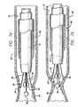
- FIG. 2is a cross-sectional view of the working end of a first embodiment of a catheter in accordance with aspects of the invention depicting the electrodes in a fully expanded position;
- FIG. 2 ais an end view of the working end of the first embodiment of the catheter taken along line 2 a — 2 a of FIG. 2;
- FIG. 3is a cross-sectional view of the working end of the first embodiment depicting the electrodes in a fully retracted position
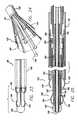
- FIG. 4is a cross-sectional view of the working end of a second catheter in accordance with principles of the invention depicting the electrodes in a fully expanded position;
- FIG. 4 ais an end view of the second embodiment of the invention taken along line 4 a — 4 a of FIG. 4;
- FIG. 5is a cross-sectional view of the working end of the second embodiment of the catheter of FIG. 4 depicting the electrodes in a fully retracted position;
- FIG. 6is a cross-sectional view of an anatomical structure containing the catheter of FIG. 2 with the electrodes in apposition with the anatomical structure;
- FIG. 6 ais an end view of the anatomical structure containing the catheter taken along line 6 a — 6 a of FIG. 6;
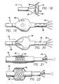
- FIGS. 7 a through 7 care cross-sectional views of the anatomical structure containing a catheter in accordance with the first embodiment of the invention and depicting the anatomical structure at various stages of ligation;
- FIG. 8is a cross-sectional view of an anatomical structure containing a catheter in accordance with the second embodiment of the invention as depicted in FIG. 4;
- FIG. 8 ais an end view of the anatomical structure containing the catheter taken along line 8 a — 8 a of FIG. 8;
- FIGS. 9 a and 9 bare cross-sectional views of the anatomical structure containing the catheter in accordance with the second embodiment of the invention and depicting the anatomical structure at various stages of ligation;
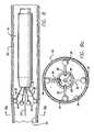
- FIG. 10is a cross-sectional view of the working end of a third embodiment of a catheter in accordance with the invention depicting the electrodes in a fully retracted position;
- FIG. 10 ais an end view of the working end of the third embodiment of the catheter taken along line 10 a — 10 a of FIG. 10;
- FIG. 11is a cross-sectional view of the working end of the third embodiment depicting the electrodes in a fully expanded position
- FIG. 12is a cross-sectional view of an anatomical structure containing the catheter of FIG. 10 with the electrodes in apposition with the anatomical structure;
- FIG. 13is a cross-sectional view of the anatomical structure containing the catheter of FIG. 10 where the anatomical structure is being ligated by the application of energy from the electrodes;
- FIG. 14is a cross-sectional view of an anatomical structure containing the catheter of FIG. 10 with the electrodes in apposition with the anatomical structure where external compression is being applied to reduce the diameter of the hollow structure before the application of energy from the electrodes to ligate the structure;
- FIG. 15is a side view of another embodiment of an electrode catheter having a balloon and a coaxial fluid channel
- FIG. 16is a view of the balloon and catheter of FIG. 15 showing the balloon inflation ports formed in an inflation sheath of the catheter, also showing the inflation lumen that communicates with the inflation ports;
- FIG. 17is a cross-sectional view of an anatomical structure containing another embodiment of the catheter having a balloon located proximal to bowable arms with electrodes, the portion of the catheter distal to the balloon having perfusion holes;
- FIG. 18is a side view of another embodiment of an electrode catheter having a covering spanning the splayed leads of the electrodes extended out the catheter;
- FIG. 19is a side view of another embodiment of an electrode catheter having a balloon and a coaxial fluid channel located proximal to expandable leads, the balloon having openings for receiving blood to maintain deployment of the balloon;
- FIG. 20is a side view of another embodiment of an electrode catheter having a balloon and a coaxial fluid channel located proximal to expandable leads, the balloon having openings for receiving blood to maintain deployment of the balloon;
- FIG. 21is a partial cross-sectional side view of another embodiment of an electrode catheter having an expandable section
- FIG. 22is a partial cross-sectional side view of the embodiment of an electrode catheter of FIG. 21 in an expanded condition
- FIG. 23is a side view of an embodiment of an electrode catheter having two pluralities of longitudinally-separated expandable electrodes in a retracted condition
- FIG. 24is a side view of the embodiment of the electrode catheter of FIG. 23 with both pluralities of the electrodes in expanded configurations;
- FIG. 25is a partial cross-sectional view of the embodiment of an electrode catheter of FIG. 23;
- FIG. 26is a side view of another embodiment of an electrode catheter having two pluralities of longitudinally-separated expandable electrodes in a retracted condition;
- FIG. 27is a side view of another embodiment of an electrode catheter having two pluralities of longitudinally-separated expandable electrodes in a retracted condition;
- FIG. 28is a side view of another embodiment of an electrode catheter having two pluralities of longitudinally-separated expandable electrodes in a retracted condition;
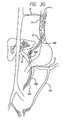
- FIG. 29is a view of a catheter used in a method in accordance with the invention to treat a hemorrhoid
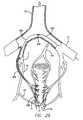
- FIG. 30is a view of a catheter used in a method in accordance with the invention to treat an esophageal varix.
- FIG. 31is a view of a catheter used in a method in accordance with the invention for ligating a fallopian tube.
- FIG. 1shown in FIG. 1 is a catheter 10 for applying energy to an anatomical structure such as a vein.
- the catheter 10includes an outer sheath 12 having a distal orifice 14 at its working end 15 .
- the connector end 17 of the outer sheath 12is attached to a handle 16 that includes an electrical connector 18 for interfacing with a power source 22 , typically an RF generator, and a microprocessor controller 23 .
- the power source 22 and microprocessor 23are usually contained in one unit.
- the controller 23controls the power source 22 in response to external commands and data from a sensor, such as a thermocouple, located at an intraluminal venous treatment site.
- the usercan select a constant power output so that automated temperature control is not present and the user can manually adjust the power output in view of the temperature on a display readout.
- the catheter 10includes an expandable electrode device 24 (partially shown) that moves in and out of the outer sheath 12 by way of the distal orifice 14 .
- the electrode deviceincludes a plurality of electrodes which can be expanded by moving the electrodes within the shaft, or by moving the outer shaft relative to the electrodes.
- FIG. 1illustrates a plurality of electrodes surrounding a single central electrode, different electrode configurations will be described for the catheter.
- a fluid port 21communicates with the interior of the outer sheath 12 .
- the catheter 10can be periodically flushed out with saline through the port 21 .
- the flushing fluidcan travel between the outer sheath and the inner sheath.
- the portalso allows for the delivery of drug therapies. Flushing out the catheter prevents the buildup of biological fluid, such as blood, within the catheter 10 .
- the treatment area of the hollow anatomical structure such as a veincan be flushed with a fluid such as saline, or a dielectric fluid, in order to evacuate blood from the treatment area of the vein so as to prevent the formation of coagulum or thrombosis.
- the use of a dielectric fluidcan minimize unintended heating effects away from the treatment area.
- the dielectric fluidprevents the current of RF energy from flowing away from the vein wall.
- the catheter 10includes a lumen which begins at the distal tip of the outer sheath 12 and runs substantially along the axis of the outer sheath 12 before terminating at the guide-wire port 20 of the handle 16 .
- a guide wirecan be introduced through the lumen of the catheter 10 for use in guiding the catheter to the desired treatment site.
- the catheteris sized to treat smaller veins, the outer diameter of the catheter may not allow for a fluid flush between the outer sheath 12 and the inner sheath 28 . However, a fluid flush can be introduced through the lumen for the guide wire in such an embodiment.
- the outer sheath 12includes a shell 44 and a tip portion 46 .
- the tip 46is preferably tapered inward at its distal end or is “nosecone” shaped.
- the tip 46can have other shapes that facilitate tracking of the catheter 10 over a guide wire and through the bends in the venous vascular system.
- the nosecone-shaped tip 46can, for example, be fabricated from a polymer having a soft durometer, such as 70 Shore A.
- the shell 44comprises a biocompatible material having a low coefficient of friction.
- the outer sheath 12is sized to fit within a venous lumen and for example may be between 5 and 9 French, which corresponds to a diameter of between 1.7 mm (0.07 in) and 3.0 mm (1.2 in), or other sizes as appropriate.
- the electrode device 24contains a number of leads, including insulated primary leads 30 and, in some embodiments, a secondary lead 31 .
- the leadsare connected to the power source 22 (FIG. 1) such that the polarity of the leads may be switched as desired.
- a microprocessor controllercan be used to switch the polarity, as well as control other characteristics of the power for the electrode device.
- the electrode devicecan operate in either a bipolar or a monopolar configuration. When adjacent primary leads 30 have opposite polarity the electrode device 24 operates as a bipolar electrode device. When the primary leads 30 are commonly charged the electrode device 24 can operate as a monopolar electrode device.
- the electrode device 24When the primary leads 30 are commonly charged, and a secondary lead 31 has an opposite polarity, the electrode device 24 operates as a bipolar electrode device.
- the inventionis not limited to four primary leads 30 ; more or fewer leads may be used in either embodiment.
- the number of leadscan be dependent on the size or diameter of the hollow anatomical structure to be treated.
- the apposed electrodesshould be kept within a certain distance of one another. Larger vessels may require more primary leads to ensure proper current density and proper heat distribution.
- each electrode 34has a hemispherical shape.
- the electrodecan have either a generally spherical shape or a spoon shape.
- the electrodeshave a spoon shape which can be combined to form a sphere or other shape so as to minimize its profile when the vein collapses.
- the electrodes 34are either integrally formed at the distal end 32 , soldered, or otherwise formed to the distal end of each primary lead 30 .
- the distal end 32when the distal end 32 is referred to as acting as an electrode, this is not limited to where the electrode 34 is integrally formed at the distal end 32 .
- the distal endcan apply energy to the surrounding tissue where there is an electrode integrally formed at the distal end, or where an electrode is separately soldered to the distal end, or where there is another energy delivery device located at the distal end.
- the electrode 34typically has a diameter greater than the diameter of the primary lead 30 .
- the primary lead 30may have a diameter ranging from 0.18 mm (0.007 in.) to 0.28 mm (0.011 in.), while the electrode 34 has a diameter of 0.36 mm (0.014 in.) to 0.51 mm (0.020 in.).
- the primary leads 30 and the electrodes 34are preferably made from a biologically-compatible material such as stainless steel.
- the insulation surrounding the primary leads 30generally has a thickness of between 0.03 mm (0.001 in.) and 0.06 mm (0.0025 in.), resulting in a combined lead-insulation diameter of between 0.23 mm (0.009 in.) and 0.41 mm (0.016 in.).
- each primary lead 30is strip-shaped with a width from 0.76 mm (0.03 in.) to 1.0 mm (0.04 in) and a thickness of approximately 0.13 mm (0.005 in.), while the secondary lead 31 is typically tubular-shaped.
- a hemispherical electrode 34is shaped at the distal end, as for example, by sanding down a sixteenth-inch (1.6 mm) diameter sphere which is soldered to the distal end 32 of the primary lead 30 .
- the electrodescan also be constructed by stamping the desired shape or configuration from the conductive lead.
- the electrodeis integral with the lead, and the remainder of the lead is insulated.
- the distal end 33 of the secondary lead 31preferably includes a generally spherically-shaped electrode 35 .
- An alignment device 36arranges the leads 30 , 31 such that they are mounted to the catheter at only their proximal ends and so that separation is maintained between the leads within, and distal to the alignment device.
- the leadscan form cantilevers when mounted on the alignment device.
- a preferred configuration of the alignment device 36includes a plurality of off-center, axially-aligned lumina 38 which are substantially symmetrically positioned relative to the axis of the alignment device 36 .
- the alignment device 36is formed, for example, by extruding the plurality of axially-aligned lumina 38 through a solid cylinder composed of a dielectric material, such as polyamide.
- Each lead 30passes through an individual off-center lumen 38 and exits out the rear of the alignment device 36 .
- the alignment device 36may further include a central lumen 48 that may be aligned with the axis.
- the central lumen 48is used for accepting a guide wire or for the delivery or perfusion of medicant and cooling solution to the treatment area during application of RF energy.
- the central lumen 48may be used for the secondary lead 31 .
- the alignment device 36may also further include an auxiliary lumen 47 for additional leads, such as the leads of a thermocouple used as a temperature sensor.
- the alignment device 36comprises a dielectric material to prevent or minimize any coupling effect the leads 30 , 31 may have with each other and, if present, the guide wire.
- the length of the alignment deviceis, for example, 12.5 mm (0.5 in.) to 19.0 mm (0.75 in.) in one embodiment. However, these dimensions are provided for purposes of illustration and not by way of limitation.
- the inner sheath 28is attached to the alignment device 36 and extends beyond the rear 37 of the alignment device.
- the inner sheath 28completely surrounds the exterior wall of the alignment device 36 and is mounted to it by adhesive or press fit or in other manner such that it remains in a fixed position relative to the inner sheath.
- the inner sheath and alignment devicecan act as an inner member relative to the outer sheath.
- the inner sheath 28comprises a biocompatible material with a low coefficient of friction.
- the inner sheath 28provides a pathway for the interconnection between the leads 30 , 31 and the electrical connector 18 (FIG. 1 ). This interconnection may occur in any of several ways.
- the leads 30 , 31themselves may be continuous and run the entire length of the inner sheath 28 .
- the positively charged leads 30 , 31may couple with a common positively charged conductor housed in the inner sheath 28 .
- the negatively charged leads 30 , 31may couple with a common negative conductor.
- the leads 30 , 31are connected to a conductor that allows for the polarity of the leads to be switched.
- the conductormay comprise, for example, a 36 gauge copper lead with a polyurethane coating.
- the couplingmay occur at any point within the inner sheath 28 . To reduce the amount of wire contained in the catheter, it is advantageous to couple the leads 30 , 31 at the point where the leads exit the rear 37 of the alignment device 36 .
- bonding material 40surround the leads 30 , 31 at the front end of the alignment device 36 .
- the leads 30 , 31exit through the distal orifice 14 as the outer sheath 12 is retracted backwards over the alignment device 36 .
- the inwardly tapered tip 46impedes the retracting movement of the outer sheath 12 to prevent the exposure of the alignment device 36 .
- FIG. 3shows the leads 30 and 31 in the retracted position where all leads are within the nosecone-shaped tip portion 46 and the outer shell 44 .
- the alignment device 36has been moved relative to the outer shell 44 .
- the soft noseconeprovides an atraumatic tip for when the catheter is maneuvered through the tortuous venous system.
- the electrode at the distal end of the secondary lead 31can be sized to approximately the same size as the opening formed in the nosecone 46 .
- the noseconeforms a closed atraumatic tip together with the electrode of the secondary lead when the alignment device is retracted into the outer sheath of the catheter. This can present an atraumatic tip even where the nosecone is not constructed from a material having a soft durometer.
- the alignment device 36is attached to the outer sheath 12 and thereby remains immobile in relation to it.
- the inner sheath 28is movably positioned at the rear of the alignment device 36 and again provides a pathway for the interconnection between the primary leads 30 and the electrical connector 18 (FIG. 1 ).
- the inner sheath 28contains a guide-wire tube 49 that runs the entire length of the inner sheath.
- the guide-wire tube 49is aligned to communicate with the central lumen 48 of the alignment device 36 at one end and with the guide-wire port 20 (FIG. 1) at the other end.
- the primary leads 30may be continuous and run the entire length of the inner sheath 28 or they may be coupled to common leads as previously described.
- the primary leads 30are secured to the front end 27 of the inner sheath 28 , as for example with a potting material 50 , so that the movement of the inner sheath 28 results in a corresponding movement of the primary leads 30 through the lumina 38 of the alignment device 36 .
- the primary leads 30are not secured to the alignment device 36 and in essence are free-floating leads in the axial direction.
- the primary leads 30travel through the alignment device 36 and exit through the distal orifice 14 as the front end of the inner sheath 28 is moved toward the rear 37 of the alignment device 36 .
- the primary leads 30are formed, e.g., arced or bent, to move away from each other and thereby avoid contact.
- the “distal portion” of the primary leads 30is the portion of the lead which extends from the front end of the alignment device 36 when the leads are fully extended through the distal orifice 14 . It is preferred that the distal portions 42 are formed to move radially outward from each other relative to the axis of the alignment device 36 and form a symmetrical arrangement. This is shown in both the embodiments of FIG. 2 a and FIG. 4 a .
- the degree of arc or bend in the primary leads 30may be any that is sufficient to radially expand the leads as they exit the outer sheath 12 through the distal orifice 14 .
- the electrodesare preferably partially embedded in the vein wall to assure full contact.
- the rounded portion of the electrodeis embedded into the vein wall to achieve full surface apposition so that the entire uninsulated surface area of the electrode is in contact with venous tissue for effective current distribution.
- the surface area of the electrodes in contact with the venous tissuepreferably is sufficient to avoid a high current density which may lead to spot heating of the venous tissue.
- the heating effectis preferably distributed along a circumferential band of the vein.
- the apposed electrodesshould be spaced no more than 4 or 5 millimeters from one another along the circumference of the vein.
- the electrode arrangementis related to the size or diameter of the vein being treated.
- Other properties of the primary leads 30such as lead shape and insulation thickness, affect the push force of the lead and the degree of arc or bend must be adjusted to compensate for these factors.
- a wire having a diameter of between 0.18 mm (0.007 in) and 0.28 mm (0.011 in) with a total insulation thickness of between 0.05 mm (0.002 in) to 0.13 mm (0.005 in)is arced or bent at an acute angle to provide sufficient apposition with the anatomical structure. It is to be understood that these dimensions are provided for illustrative purposes, and not by way of limitation.
- the leadsmay be straight but are mounted in the alignment device at an angle such that they are normally directed outward.
- the primary leads 30be strip-shaped, that is rectangular in cross section, with dimensions, for example, of a width from 0.76 mm (0.030 in.) to 1.0 mm (0.039 in) and a thickness of approximately 0.13 mm (0.005 in.).
- the rectangular cross sectionprovides increased resistance to bending in the width dimension but allows bending more freely in the thickness dimension.
- This strip-shaped configuration of the primary leads 30is shown in FIGS. 2, 2 a , and 3 and provides for increased stability in the lateral direction while allowing the necessary bending in the radial direction. In FIGS.
- each primary leadcomprises a rectangular cross section mounted in relation to the catheter such that the thinner dimension of the rectangular cross section is aligned with the direction of expansion of the lead.
- the leadsare less likely to bend sideways when expanded outward, and a uniform spacing between leads is more assured. Uniform spacing promotes uniform heating around the venous tissue which is in apposition with the electrodes at the distal ends of the leads.
- the length of the distal portion of the leads 30also affects the configuration of the electrode device 24 .
- the maximum distance between two mutually opposed electrodes 34i.e., the effective diameter of the electrode device 24 , is affected by the bend degree and length of the distal portion 42 .
- the longer the length of the distal portion 42the greater the diameter of the electrode device 24 . Accordingly, by changing the distal portion 42 length and arc or bend degree, the catheter 10 can be configured for use in differently sized anatomical structures.
- leads 30 , 31can be employed with the catheter.
- the number of leads 30 , 31is limited by the diameter of the alignment device 36 and the number of lumina 36 , 38 , 47 that can be extruded through the alignment device.
- an even number of primary leads 30are preferably available to form a number of oppositely charged electrode pairs.
- the electrodes in apposition with the anatomical structureshould be maintained within a certain distance of each other.
- any number of commonly charged leads 30can be present.
- distribution of RF energy through the anatomical tissueis obtained by creating a return path for current through the tissue by providing a return device at a point external from the tissue, such as a large metal pad.
- an actuator 25controls the extension of the electrode device 24 through the distal orifice 14 .
- the actuator 25may take the form of a switch, lever, threaded control knob, or other suitable mechanism, and is preferably one that can provide fine control over the movement of the outer sheath 12 or the inner sheath 28 , as the case may be.
- the actuator 25(FIG. 1) interfaces with the outer sheath 12 (FIGS. 2, 2 a and 3 ) to move it back and forth relative to the inner sheath 28 .
- the actuator 25(FIG. 1) interfaces with the inner sheath 28 (FIGS. 4, 4 a and 5 ) to move it back and forth relative to the outer sheath 12 .
- the relative position between the outer sheath and inner sheathis thus controlled, but other control approaches may be used.
- the catheter 10includes a temperature sensor 26 , such as a thermocouple.
- the temperature sensor 26is mounted in place on an electrode 34 so that the sensor 26 is nearly or is substantially flush with the exposed surface of the electrode 34 .
- the sensor 26is shown in the drawings as protruding from the electrodes for clarity of illustration only.
- the sensor 26senses the temperature of the portion of the anatomical tissue that is in apposition with the exposed electrode surface. Monitoring the temperature of the anatomical tissue provides a good indication of when shrinkage of the tissue is ready to begin.
- a temperature sensor 26 placed on the electrode facing the anatomical tissueprovides an indication of when shrinkage occurs (70° C.
- the temperature sensor 26interfaces with the controller 23 (FIG. 1) through a pair of sensor leads 45 which preferably run through the auxiliary lumen 47 and then through the inner sheath 28 .
- the signals from the temperature sensor 26are provided to the controller 23 which controls the magnitude of RF energy supplied to the electrodes 34 in accordance with the selected temperature criteria and the monitored temperature.
- Impedancecan be used to detect the onset of coagulum formation.
- the catheterin the operation of one embodiment of the catheter 10 , the catheter is inserted into a hollow anatomical structure, such as a vein 52 .
- the catheteris similar to the embodiment discussed in connection with FIGS. 2 and 3.
- the catheter 10further includes an external sheath 60 through which a fluid can be delivered to the treatment site.
- the fluid port(not shown) communicates with the interior of the external sheath 60 , and fluid is delivered from between the external sheath 60 and the outer sheath 12 .
- the external sheath 60surrounds the outer sheath 12 to form a coaxial channel through which fluid may be flushed.
- Fluoroscopy, ultrasound, an angioscope imaging technique, or other techniquemay be used to direct the specific placement of the catheter and confirm the position in the vein.
- the actuator(not shown) is then operated to shift the outer sheath relative to the inner sheath by either retracting the outer sheath 12 backward or advancing the inner sheath 28 forward to expose the leads 30 , 31 through the distal orifice 14 .
- the primary leads 30expand radially outward relative to the axis of the alignment device 36 , while the secondary lead 31 remains substantially linear.
- the primary leads 30continue to move outward until apposition with the vein wall 54 occurs and the outward movement of the primary leads 30 is impeded.
- the primary leads 30contact the vein along a generally circumferential band of the vein wall 54 . This outward movement of the primary leads 30 occurs in a substantially symmetrical fashion. As a result, the primary-lead electrodes 34 are substantially evenly spaced along the circumferential band of the vein wall 54 . The central-lead electrode 35 is suspended within the vein 52 without contacting the vein wall 54 .
- the power supply 22is activated to provide suitable RF energy.
- suitable frequencyis 510 kHz.
- One criterion used in selecting the frequency of the energy to be appliedis the control desired over the spread, including the depth, of the thermal effect in the venous tissue. Another criterion is compatibility with filter circuits for eliminating RF noise from thermocouple signals.
- the primary leads 30are initially charged such that adjacent leads are oppositely charged while the secondary lead is electrically neutral. These multiple pairs of oppositely charged leads 30 form active electrode pairs to produce an RF field between them.
- discrete RF fieldsare set up along the circumferential band of the vein wall 54 . These discrete fields form a symmetrical RF field pattern along the entire circumferential band of the vein wall 54 , as adjacent electrodes 34 of opposite polarity produce RF fields between each other.
- a uniform temperature distributioncan be achieved along the vein wall being treated.
- the RF energyis converted within the adjacent venous tissue into heat, and this thermal effect causes the venous tissue to shrink, reducing the diameter of the vein.
- a uniform temperature distribution along the vein wall being treatedavoids the formation of hot spots in the treatment area while promoting controlled uniform reduction in vein diameter.
- the thermal effectproduces structural transfiguration of the collagen fibrils in the vein.
- the collagen fibrilsshorten and thicken in cross-section in response to the heat from the thermal effect.
- the energycauses the vein wall 54 to collapse around the primary-lead electrodes 34 .
- the wall 54continues to collapse until further collapse is impeded by the electrodes 34 .
- the electrodesare pressed farther and farther together by the shrinking vein wall 54 until they touch and at that point, further collapse or ligation of the wall 54 is impeded.
- the polarity of the primary-lead electrodesis switched so that all primary-lead electrodes are commonly charged.
- the switching of polarity for the leadsneed not be instantaneous.
- the application of RF energycan be ceased, the polarity switched, and then RF energy is applied again at the switched polarity.
- the secondary-lead electrode 35is then charged so that its polarity is opposite that of the primary-lead electrodes 34 .
- the RF fieldis set up between the primary-lead electrodes 34 and the secondary-lead electrode 35 .
- the catheter 10is then pulled back while energy is applied to the electrode device.
- the primary-lead electrodes 34remain in apposition with the vein wall 54 while the secondary-lead electrode 35 comes in contact with the portion of the vein wall previously collapsed by the primary-lead electrodes 34 .
- RF energypasses through the vein wall 54 between the primary-lead electrodes 34 and the secondary-lead electrode 35 and the vein wall continues to collapse around the secondary-lead electrode 35 as the catheter 10 is being retracted.
- ligation in accordance with this methodresults in an occlusion along a length of the vein 52 .
- a lengthy occlusionas opposed to an acute occlusion, is stronger and less susceptible to recanalization.
- the catheter 10 having both primary and secondary leadsis operated in a monopolar manner.
- the secondary-lead electrode 35remains neutral, while the primary leads 30 are commonly charged and act in conjunction with an independent electrical device, such as a large low-impedance return pad (not shown) placed in external contact with the body, to form a series of discrete RF fields.
- a large low-impedance return pad(not shown) placed in external contact with the body, to form a series of discrete RF fields.
- These RF fieldsare substantially evenly spaced around the circumference of the vein and travel along the axial length of the vein wall causing the vein wall to collapse around the primary-lead electrodes.
- the secondary-lead electrodeUpon collapse of the vein wall, the secondary-lead electrode is charged to have the same polarity as that of the primary-lead electrodes. The electrode device is retracted and the vein wall collapses as described in the bipolar operation.
- the application of RF energyis substantially symmetrically distributed through the vein wall, regardless of the diameter of the vein 52 .
- This symmetrical distribution of RF energyincreases the predictability and uniformity of the shrinkage and the strength of the occlusion.
- the uniform distribution of energyallows for the application of RF energy for a short duration and thereby reduces or avoids the formation of heat-induced coagulum on the electrodes 34 .
- the leads, including the non-convex outer portion of the electrode,are insulated to further prevent heating of the surrounding blood.
- Fluidcan be delivered before and during RF heating of the vein being treated through a coaxial channel formed between the external sheath 60 and the outer sheath 12 . It is to be understood that another lumen can be formed in the catheter to deliver fluid to the treatment site.
- the delivered fluiddisplaces or exsanguinates blood from the vein so as to avoid heating and coagulation of blood. Fluid can continue to be delivered during RF treatment to prevent blood from circulating back to the treatment site.
- the delivery of a dielectric fluidincreases the surrounding impedance so that RF energy is directed into the tissue of the vein wall.
- FIGS. 8, 8 a , 9 a and 9 bin the operation of an alternate embodiment of the catheter 10 that may be used with a guide wire 53 .
- the catheter 10is inserted into a hollow anatomical structure, such as a vein 52 .
- the guide wire 53is advanced past the point where energy application is desired.
- the catheter 10is then inserted over the guide wire 53 by way of the central lumen 48 and the guide wire tube 49 (FIG. 4) and is advanced over the guide wire through the vein to the desired point.
- the guide wire 53is typically pulled back or removed before RF energy is applied to the electrode device 24 .
- the actuator 25(FIG. 1) is then manipulated to either retract the outer sheath 12 backward, or advance the inner sheath 28 forward to expose the leads 30 through the distal orifice 14 .
- the leads 30exit the distal orifice 14 and expand radially outward relative to the axis of the alignment device 36 .
- the leads 30continue to move outward until apposition with the vein wall 54 occurs.
- the leads 30contact the vein along a generally circumferential band of the vein wall 54 . This outward movement of the leads occurs in a substantially symmetrical fashion.
- the electrodes 34are substantially evenly spaced along the circumferential band of the vein wall 54 .
- the electrodescan be spaced apart in a staggered fashion such that the electrodes do not lie along the same plane.
- adjacent electrodescan extend different lengths from the catheter so that a smaller cross-sectional profile is achieved when the electrodes are collapsed toward one another.
- the power supply 22is activated to provide suitable RF energy to the electrodes 34 so that the catheter 10 operates in either a bipolar or monopolar manner as previously described.
- the energycauses the vein wall 54 to collapse around the electrodes 34 causing the leads to substantially straighten and the electrodes to cluster around each other.
- the wall 54continues to collapse until further collapse is impeded by the electrodes 34 (FIG. 9 b ). At this point the application of energy may cease.
- the electrodescan be configured to form a shape with a reduced profile when collapsed together.
- the electrodescan also be configured and insulated to continue applying RF energy after forming a reduced profile shape by the collapse of the vein wall.
- the catheter 10can be pulled back to ligate the adjacent venous segment. If a temperature sensor 26 is included, the application of energy may cease prior to complete collapse if the temperature of the venous tissue rises above an acceptable level as defined by the controller 23 .
- fluidcan be delivered before and during RF heating of the vein being treated.
- the fluidcan displace blood from the treatment area in the vein to avoid the coagulation of blood.
- the fluidcan be a dielectric medium.
- the fluidcan include an anticoagulant such as heparin which can chemically discourage the coagulation of blood at the treatment site.
- the actuator mechanismcauses the primary leads to return to the interior of the outer sheath 12 .
- Either the outer sheath or the inner sheathis moved to change the position of the two elements relative to one another.
- the catheter 10may be moved to another venous section where the ligation process is repeated.
- the catheter 10is removed from the vasculature. The access point of the vein is then sutured closed, or local pressure is applied until bleeding is controlled.
- the inner member or sheath 28is contained within the outer sheath 12 .
- the inner sheathis preferably constructed from a flexible polymer such as polyimide, polyethylene, or nylon, and can travel the entire length of the catheter. The majority of the catheter should be flexible so as to navigate the tortuous paths of the venous system.
- a hypotube having a flared distal end 39 and a circular cross-sectional shapeis attached over the distal end of the inner sheath 28 .
- the hypotubeis preferably no more than about two to three centimeters in length.
- the hypotubeacts as part of the conductive secondary lead 31 .
- An uninsulated conductive electrode sphere 35is slipped over the hypotube.
- the flared distal end of the hypotubeprevents the electrode sphere from moving beyond the distal end of the hypotube.
- the sphereis permanently affixed to the hypotube, such as by soldering the sphere both front and back on the hypotube.
- the majority or the entire surface of the spherical electrode 35remains uninsulated.
- the remainder of the hypotubeis preferably insulated so that the sphere-shaped distal end can act as the electrode.
- the hypotubecan be covered with an insulating material such as a coating of parylene.
- the interior lumen of the hypotubeis lined by the inner sheath 28 which is attached to the flaired distal end of the hypotube by adhesive such as epoxy.
- a plurality of primary leads 30Surrounding the secondary lead 31 and sphere-shaped electrode 35 are a plurality of primary leads 30 which preferably have a flat rectangular strip shape and can act as arms. As illustrated in FIG. 11, the plurality of primary leads are preferably connected to common conductive rings 62 . This configuration maintains the position of the plurality of primary leads, while reducing the number of internal electrical connections.
- the rings 62are attached to the inner sheath 28 . The position of the rings and the primary leads relative to the outer sheath follows that of the inner sheath. As earlier described, the hypotube of the secondary lead 31 is also attached to the inner sheath 28 . Two separate conductive rings can be used so that the polarity of different primary leads can be controlled separately.
- adjacent primary leadscan be connected to one of the two separate conductive rings so that the adjacent leads can be switched to have either opposite polarities or the same polarity.
- the ringsare preferable spaced closely together, but remain electrically isolated from one another along the inner sheath. Both the rings and the hypotube are coupled with the inner sheath, and the primary leads 30 that are connected to the rings move together with and secondary lead while remaining electrically isolated from one another. Epoxy or another suitable adhesive can be used to attach the rings to the inner sheath.
- the primary leads from the respective ringseach alternate with each other along the circumference of the inner sheath. The insulation along the underside of the leads prevents an electrical short between the rings.
- the ring and primary leadsare attached together to act as cantilevers where the ring forms the base and the rectangular primary leads operate as the cantilever arms.
- the leads 30are connected to the ring and are formed to have an arc or bend such that the leads act as arms which tend to spring outwardly away from the catheter and toward the surrounding venous tissue. Insulation along the underside of the leads and the rings prevents unintended electrical coupling between the leads and the opposing rings.
- the leadsare formed straight and connected to the ring at an angle, such that the leads tend to expand or spring radially outward from the ring. The angle at which the leads are attached to the ring should be sufficient to force the primary distal ends and electrodes 34 through blood and into apposition with the vein wall.
- the rectangular cross section of the leads 30can provide increased stability in the lateral direction while allowing the necessary bending in the radial direction.
- the leads 30are less likely to bend sideways when expanded outward, and a uniform spacing between leads is more assured. Uniform spacing between the leads 30 and the distal ends promotes uniform heating around the vein by the electrodes 34 .
- the distal ends of the primary leads 30are uninsulated to act as electrodes 34 having a spoon or hemispherical shape.
- the leadscan be stamped to produce an integral shaped electrode at the distal end of the lead.
- the uninsulated outer portion of the distal end electrode 34 which is to come into apposition with the wall of the anatomical structureis preferably rounded and convex.
- the flattened or non-convex inner portion of the distal endis insulated to minimize any unintended thermal effect, such as on the surrounding blood in a vein.
- the distal end electrodes 34are configured such that when the distal ends are forced toward the inner sheath 12 , as shown in FIG. 10 a , the distal ends combine to form a substantially spherical shape with a profile smaller than the profile for the spherical electrode 35 at the secondary distal end.
- the outer sheath 12can slide over and surround the primary and secondary leads 30 , 31 .
- the outer sheath 12includes an orifice which is dimensioned to have approximately the same size as the spherical electrode 35 at the secondary distal end which functions as an electrode. A close or snug fit between the electrode 35 at the secondary distal end and the orifice of the outer sheath 12 is achieved. This configuration provides an atraumatic tip for the catheter.
- the electrode 35 secondary distal endis preferably slightly larger than the orifice.
- the inner diameter of the outer sheath 12is approximately the same as the reduced profile of the combined primary distal end electrodes 34 .
- the diameter of the reduced profile of the combined primary distal end electrodes 34is preferably less than the inner diameter of the outer sheath.
- a fluid portcan communicate with the interior of the outer sheath 12 so that fluid can be flushed between the outer sheath 12 and the inner sheath 28 .
- a fluid portcan communicate with a central lumen 48 in the hypotube which can also accept a guide wire.
- the catheter 10can be periodically flushed with saline which can prevent the buildup of biological fluid, such as blood, within the catheter 10 .
- a guide wirecan be introduced through the lumen 48 for use in guiding the catheter to the desired treatment site.
- a fluidcan be flushed or delivered though the lumen as well. If a central lumen is not desired, the lumen of the hypotube can be filled with solder.
- the primary leads 30 and the connecting ringsare connected to a power source 22 such that the polarity of the leads may be switched as desired.
- the electrode device 24to operate in either a bipolar or a monopolar configuration.
- a bipolar electrode operationis available.
- a monopolar electrode operationis available in combination with a large return electrode pad placed in contact with the patient.
- a secondary lead 31has an opposite polarity
- a bipolar electrode operationis available. More or fewer leads may be used. The number of leads can be dependent on the size or diameter of the hollow anatomical structure to be treated.
- the catheter 10can include a temperature sensor, such as a thermocouple, mounted in place on the distal end or electrode 34 so that the sensor is substantially flush with the 30 exposed surface of the electrode 34 .
- the sensorsenses the temperature of the portion of the anatomical tissue that is in apposition with the exposed electrode surface.
- Application of the RF energy from the electrodes 34is halted or reduced when the monitored temperature reaches or exceeds the specific temperature that was selected by the operator, such as the temperature at which anatomical tissue begins to cauterize.
- the catheterin the operation of one embodiment of the catheter 10 , the catheter is inserted into a hollow anatomical structure, such as a vein. Fluoroscopy, ultrasound, an angioscope imaging technique, or another technique may be used to direct and confirm the specific placement of the catheter in the vein.
- the actuatoris then operated to retract the outer sheath 12 to expose the leads 30 , 31 . As the outer sheath no longer restrains the leads, the primary leads 30 move outward relative to the axis defined by the outer sheath, while the secondary lead 31 remains substantially linear along the axis defined by the outer sheath.
- the primary leads 30continue to move outward until the distal end electrode 34 of the primary leads are placed in apposition with the vein wall 54 occurs and the outward movement of the primary leads 30 is impeded.
- the primary leads 30contact the vein along a generally circumferential area of the vein wall 54 . This outward movement of the primary leads 30 occurs in a substantially symmetrical fashion so that the primary distal end electrodes 34 are substantially evenly spaced.
- the central-lead electrode 35is suspended within the vein without contacting the vein wall 54 .
- the power supply 22is activated to provide suitable RF energy.
- the primary leads 30are initially charged such that adjacent leads are oppositely charged while the secondary lead is electrically neutral.
- These multiple pairs of oppositely charged leads 30form active electrode pairs to produce an RF field between them, and form a symmetrical RF field pattern along a circumferential band of the vein wall to achieve a uniform temperature distribution along the vein wall being treated.
- the RF energyproduces a thermal effect which causes the venous tissue to shrink, reducing the diameter of the vein.
- the energycauses the vein wall 54 to collapse until further collapse is impeded by the electrodes 34 .
- the electrodesare pressed closer together by the shrinking vein wall.
- the electrodes 34are pressed together to assume a reduced profile shape which is sufficiently small so that the vein is effectively ligated.
- the polarity of the primary-lead electrodesis switched so that all of the primary-lead electrodes are commonly charged.
- the secondary-lead electrode 35is then charged so that its polarity is opposite that of the primary-lead electrodes 34 .
- the electrode at the distal end of the secondary leadcan also come into contact with the a portion of the vein wall so that an RF field is created between the primary electrodes 34 and the secondary electrode 35 .
- the catheter 10is pulled back to ensure apposition between the electrodes at the distal ends of the leads and the vein wall.
- the primary-lead electrodes 34remain in apposition with the vein wall 54 while the secondary-lead electrode 35 comes in contact with the portion of the vein wall previously collapsed by the primary-lead electrodes 34 .
- RF energypasses through the venous tissue between the primary-lead electrodes 34 and the secondary-lead electrode 35 .
- Ligation as the catheter is being retractedproduces a lengthy occlusion which is stronger and less susceptible to recanalization than an acute point occlusion.
- the secondary-lead electrode 35In a monopolar operation, the secondary-lead electrode 35 remains neutral, while the primary leads 30 are commonly charged and act in conjunction with an independent electrical device, such as a large low-impedance return pad (not shown) placed in external contact with the body, to form RF fields substantially evenly spaced around the circumference of the vein.
- an independent electrical devicesuch as a large low-impedance return pad (not shown) placed in external contact with the body, to form RF fields substantially evenly spaced around the circumference of the vein.
- the thermal effect produced by those RF fields along the axial length of the vein wallcauses the vein wall to collapse around the primary-lead electrodes.
- the secondary-lead electrodeUpon collapse of the vein wall, the secondary-lead electrode is charged to have the same polarity as that of the primary-lead electrodes. The electrode device is retracted as described in the bipolar operation.
- the application of RF energyis substantially symmetrically distributed through the vein wall.
- the electrodesshould be spaced no more than 4 or 5 millimeters apart along the circumference of the vein, which defines the target vein diameter for a designed electrode catheter. Where the electrodes are substantially evenly spaced in a substantially symmetrical arrangement, and the spacing between the electrodes is maintained, a symmetrical distribution of RF energy increases the predictability and uniformity of the shrinkage and the strength of the occlusion.
- an external tourniquetsuch as an elastic compressive wrap or an inflatable bladder with a window transparent to ultrasound, is used to compress the anatomy, such as a leg, surrounding the structure to reduce the diameter of the vein.
- the compressive force being applied by the tourniquetmay effectively ligate the vein, or otherwise occlude the vein by flattening the vein, for certain veins, this compressive force will not fully occlude the vein.
- a fixed diameter electrode catheter in this instancewould not be effective.
- the electrodes 34 which are expanded outward by the formed leads 30can accommodate this situation.
- the reduction in vein diameterassists in pre-shaping the vein to prepare the vein to be molded to a ligated state.
- the use of an external tourniquetalso exsanguinates the vein and blood is forced away from the treatment site. Coagulation of blood during treatment can be avoided by this procedure. Energy is applied from the electrodes to the exsanguinated vein, and the vein is molded to a sufficiently reduced diameter to achieve ligation. The external tourniquet can remain in place to facilitate healing.
- the cathetercan be pulled back during the application of RF energy to ligate an extensive section of a vein. In doing so, instead of a single point where the diameter of the vein has been reduced, an extensive section of the vein has been painted by the RF energy from the catheter. Retracting the catheter in this manner produces a lengthy occlusion which is less susceptible to recanalization.
- the combined use of the primary and secondary electrodescan effectively produce a reduced diameter along an extensive length of the vein.
- the cathetercan be moved while the tourniquet is compressing the vein, of after the tourniquet is removed.
- fluidcan be delivered to the vein before RF energy is applied to the vein.
- the delivered fluiddisplaces blood from the treatment site to ensure that blood is not present at the treatment site, even after the tourniquet compresses the vein.
- an ultrasound transduceris used to monitor the flattening or reduction of the vein diameter from the compressive force being applied by the inflating bladder.
- the windowcan be formed from polyurethane, or a stand-off of gel contained between a polyurethane pouch.
- a gelcan be applied to the window to facilitate ultrasound imaging of the vein by the transducer.
- Ultrasound visualization through the windowallows the operator to locate the desired venous treatment area, and to determine when the vein has been effectively ligated or occluded. Ultrasound visualization assists in monitoring any pre-shaping of the vein in preparation of being molded into a ligated state by the thermal effect produced by the RF energy from the electrodes.
- the actuatorAfter completing the procedure for a selected venous section, the actuator causes the leads 30 to return to the interior of the outer sheath 12 . Once the leads 30 are within the outer sheath 12 , the catheter 10 may be moved to another venous section where the ligation process is repeated.
- a balloon 64is located on the catheter, and can be inflated through ports 66 to occlude the vein.
- the inflated balloonobstructs blood flow and facilitates the infusion of a high-impedance fluid to the vein in order to reduce the occurrence of coagulation by directing the energy into the vein wall.
- the inflation of the balloon to occlude the vein before the application of energycan obviate the use of the tourniquet to occlude the vein.
- thisalso allows the vein to be occluded even for the deep veins where a compressive tourniquet may not be able to compress the vein to occlusion. It is to be understood that other mechanisms can be used to expand the diameter of the catheter to create an impermeable barrier that occludes the vein.
- Fluid 61can be delivered after inflation of the balloon 64 and before the RF heating of the vein being treated through a coaxial channel 62 formed between the external sheath 60 and the outer sheath 12 .
- another lumencan be formed in the catheter to deliver fluid to the treatment site.
- the lumen through which the guide wire is passedmay be used for the delivery of fluid.
- the delivered fluiddisplaces or exsanguinates the remaining blood from the treatment area of the vein so as to avoid heating and coagulation of blood. Fluid can continue to be delivered during RF treatment to prevent blood from circulating back to the treatment site.
- the delivery of a high-dielectric fluidincreases the surrounding impedance so that RF energy is directed into the tissue of the vein wall.
- the vein wallcan reach the desired temperature more rapidly than in the case where energy is permitted to reach the blood, which has a cooling effect. Additionally, blood clotting is avoided with this approach, because the blood has been replaced with another fluid such as deionized water mixed with heparin to displace blood and prevent the formation of blood clots.
- FIG. 16A partial cross-sectional view of this embodiment is shown in FIG. 16, where an inflation sheath 70 surrounds the external sheath 60 to provide a coaxial inflation lumen 72 for the balloon 64 .
- the inflation lumen 72is in fluid communication with the ports 66 .
- Saline or any other suitable fluidcan be used to inflate the balloon.
- the balloon 64can be used in combination with bowable members or arms 76 having electrodes, where perfusion holes 78 are formed in the catheter between the balloon 64 and the bowable arms 76 .
- the balloon 64 in this embodimentis inflated through a balloon inflation lumen 72 (as shown in FIG. 16 ).
- the use of bowable arms for treating veinsis discussed in U.S. patent application Ser. No. 08/610,911, which is hereby incorporated by reference.
- the armscan be constructed so as to spring radially outward from the catheter, yet offer little resistance in moving back toward the catheter as the vein diameter is diminished to occlusion.
- An anti-coagulant or saline or a high-impedance fluidcan be introduced or flushed through the perfusion holes 78 in the catheter.
- the high-impedance fluidforces blood away from the venous treatment area and prevents the energy from being dissipated in a more conductive medium such as blood.
- a flexible covering 80is wrapped around or inside the leads 30 of the electrodes 34 to prevent blood flow in the vein.
- the covering 80spans the area between the splayed leads along the circumference of the catheter when the leads are extended out the opening, such that the webbed covering blocks blood flow within the vein.
- the coveringmay be thought of as webbing or an umbrella to keep blood on one side away from the electrodes.
- the covering 80should be impermeable to fluid. Suitable materials include PET and nylon.
- Elastomeric materialsare also suitable as the leads will need to move close together as they are retracted, and interference with the movement of the leads as the vein diameter is reduced by the application of energy is preferably minimized.
- this embodimentis illustrated with only primary leads, it is to be understood that this embodiment is not so limited and that a secondary lead may be included with the catheter as well without affecting the use of the covering.
- the coveringoccludes the vein before the application of energy, such that the need for an external compressive tourniquet is not required to stop blood flow. Furthermore, this also allows the vein to be occluded even for the deep veins where a compressive tourniquet may not be able to compress the vein to occlusion.
- a high-impedance fluidsuch as deionized water, or an anti-coagulant such as heparin or saline, or both, or heparin with deionized water may be infused or flushed through a central lumen (not shown) similar to that shown in FIG. 4 as numeral 48 or to that shown in FIGS. 10 and 11 before the application of energy as well.
- the electrodesextend through the shaft lumen which also acts as a conduit for the fluid being flushed through a central lumen 48 (not shown).
- a sclerosing fluidmay also be delivered to the venous treatment site to enhance the dlectro-ligation effect from the application of RF energy.
- the sclerosing fluidmay be added in addition to, or in substitution of, the previously discussed fluids.
- a covering 80 having a parachute shapecan be oriented so that blood becomes trapped by the concave portion of the covering 80 and the volume of the blood maintains the deployment of the covering.
- the coveringis a balloon having openings 84 which allow blood to gather in the balloon, and expand the balloon.
- the covering 80can be permanently attached to the catheter shaft. The catheter can still be moved along the vein, even with the balloon in an inflated state.
- the covering 80is coupled to an outer cannula 82 surrounding the catheter shaft and connected to an actuation mechanism or lever.
- the outer cannula 82can be slid along the longitudinal axis of the catheter to allow one end of the parachute covering 80 to be moved axially along the catheter shaft.
- the movable end of the coveringis pulled away from the connecting end of the catheter to collapse the covering against the catheter.
- the cannula 82is slid toward the working end to deploy the covering 80 which then fills with blood entering through the openings 84 , thereby occluding the vein.
- the coveringexpands as it fills with blood, and when the covering comes into contact with the vein wall, the vein is occluded.
- Fluidas before, can be infused either through perfusion holes 78 or a coaxial channel 48 (not shown).
- the catheter 10includes an expandable section having a skeleton 90 disposed along a portion of the working end of the catheter.
- the skeleton 90is more flexible than the surrounding shaft of the catheter, and can be constructed from a metal or polymer braid.
- a flexible membrane 92covers the skeleton 90 , with the ends of the membrane attached to the shaft of the catheter adjacent the skeleton.
- the membraneis preferably constructed from an elastomeric material.
- FIG. 22when the tip of the connecting end is moved toward the working end of the catheter, or vice versa, the skeleton 90 is deformed and forces the membrane 92 out into contact with the vein wall.
- This embodimentdoes not require a separate lumen to provide an inflation fluid to a balloon.
- the skeleton 90is preferably resilient so that it returns to its original shape once the working end and connecting end are no longer being forced toward one another.
- Mechanisms for moving the connecting end toward the working end of the catheter for expanding the diameter of a catheterare also discussed in U.S. patent application Ser. No. 08/610,911, which has been incorporated by reference.
- the expandable sectionmay be controlled separately from the extension of the electrode, the expandable section can be controlled by the same mechanism which extends the electrodes away from the catheter.
- an expandable electrode catheter 98includes two sets of expandable electrode leads 100 and 102 , although additional sets of electrode leads may be possible.
- the electrodes 104 of this embodimentare similar to the electrodes of the embodiment illustrated in FIG. 2 having electrodes with a spoon-shaped contact area. Other shapes for the electrode may be used, such as ellipses, rounded, ovals, race tracks, and others. Although only one electrode is indicated by numeral 104 in FIGS. 23 and 24, this is for purposes of clarity in the drawings only. All electrodes are meant to be indicated by numeral 104 . While each set of electrode leads may include as few as two electrode leads, the illustrated embodiment includes six electrode leads per set, although more than six electrode leads may be used as well.
- the sets of electrode leads 100 and 102are longitudinally separated from each other.
- the electrodes within each set of electrode leadsare separated from one another radially and each of those electrodes is also separated from every electrode in the other set longitudinally, due to the longitudinal separation. There therefore exists radial separation and longitudinal separation of electrodes at the working end 105 of the catheter 98 in the arrangement shown in FIGS. 23 and 24.
- Electrodes leads presented in FIGS. 23 and 24greater flexibility exists in establishing current flows through the tissue of a patient. As in previous embodiments, the electrodes expand outwardly into contact with patient tissue. Where all the electrodes of a first set of electrode leads have the same polarity, there may be an odd number of electrodes in the set, or an even number. All electrodes in the set may be connected to a common connection point, such as the conducting ring 62 shown in FIG. 11. A single conductor from the connecting end of the catheter may power all electrodes of the set by a single connection to that conducting ring. All electrodes of a second set of electrode leads may also be commonly connected at a respective conducting ring but to a different electrical potential than the first set.
- a monopolar arrangementmay also be established if desired by setting all electrodes of all electrode leads to the same electrical potential and establishing a different electrical potential outside the patient, such as at a “backplate” in contact with the skin of the patient at a selected location. Energy from the working end 105 of the catheter will then flow through the patient to the return provided by the backplate.
- the electrodes in the first set of electrode leadsmay be individually controlled so that there are electrode pairs of differing potentials in the set of leads. This would establish a bipolar approach within the first set of leads itself. If the electrodes of the second set of leads are likewise connected for different potentials among themselves, they too would provide a bipolar approach in their own set and currents would flow through patient tissue between the electrodes in each set of leads.
- Electrodes having a first polarity in the first setare aligned with the electrodes having a different polarity in the second set of leads, energy would not only flow between the bipolar electrodes within the set but would also flow to the electrodes in the other set resulting in two bipolar arrangements at the single working end of the catheter.
- Patient tissue of a length at least as great as the distance between the first and second sets of electrode leadswill receive energy as well as patient tissue between electrodes within each set of leads itself.
- a further arrangement coupled with the bipolar approach just describedwould be to also use a backplate at a different electrical potential to provide further control over the energy flow through the patient's tissue.
- energywould flow between the electrodes within each set of leads, between electrodes in different sets of leads, and between electrodes and the backplate.
- each of the electrodesmay be individually connected to a power source ( 22 , FIG. 1) and the electrical potential at each electrode can be individually controlled ( 23 , FIG. 1 ).
- This arrangementmay yield even more precise control over the current densities through patient tissue.
- the potential between the electrodes of the same setmay be reduced but the potential between those electrodes and the electrodes of the second set of leads may be increased resulting in the desired current flow densities.
- the electrodesmay be controlled so that energy flows between such electrodes and the backplate. Because each electrode is individually controlled, the level of energy it imparts to the tissue at its location is controllable.
- One factor that could affect the number of electrodes per set of electrode leadsis the diameter of the vein being treated.
- the design of the contact pad for the electrode leadscould also affect the desired number of electrodes for a given procedure.
- the electrode leads 100 , 102are formed to expand outwardly into apposition with the target tissue, yet as the target tissue shrinks, the electrodes maintain contact with that tissue and are moved inwardly by that tissue. Because of this arrangement, the leads compensate for variations in the diameter of the vein. They are therefore capable of maintaining apposition with the tissue whether or not compression of the vein or anatomical structure exists, such as by use of a pressure cuff or tourniquet.
- the tip 106 of the electrode catheter 98should have a hemispherical or another atraumatic shape.
- the tip 106may be electrically neutral, and may be fabricated from a polymer or it may be fabricated of stainless steel. Because the tip 106 has a rounded shape and is located at the distal extreme of the catheter, it may perform a guiding function when introducing the catheter to the patient.
- the double set of expandable electrodescan be used to ligate veins or other hollow anatomical structures in a manner similar to that previously described.
- the outer sheath 108can be pulled back to allow the electrode to expand outwardly from the catheter and into apposition with the wall of the lumen being treated.
- the two sets of electrodes 100 and 102apply energy to the lumen to cause it to shrink to a reduced diameter.
- the cathetercan be moved or pulled back while the energy is being applied to treat an extended area of the lumen.
- the desired area of the lumen or veinis treated (e.g., ligated) energy is no longer provided to the electrodes, and the outer sheath 108 is pushed forward to force the expanded electrodes back to an unexpanded condition.
- the cathetercan then be removed from the patient, or another section of the vein can be treated.
- FIG. 25there is shown a partial cross-section view of the catheter of FIGS. 23 and 24.
- Two pluralities of electrodes 100 and 102are shown with the electrodes of the first plurality 100 being indicated by numeral 104 and the electrodes of the second plurality 102 being indicated by numeral 150 .
- Each electrodeis formed from an electrically-conductive electrode lead 152 and 154 respectively that is electrically insulated along its length except at its distal end at which point no insulation exists thus forming the electrode.
- Each leadhas an outward bend (not shown).
- An inner tube 156includes a lumen 158 through which fluid may flow for flush or other purposes, or through which a guide wire may be positioned.
- a hypotube 160is positioned over the inner tube and layers of insulation 162 are mounted over the hypotube.
- the first plurality 100 of electrode leads 152extend proximally to a first mounting ring 164 to which all are connected.
- the second plurality 102 of electrode leads 154extend proximally to a second mounting ring 166 to which all are connected.
- the rings 164 and 166are mounted over the hypotube insulation so that no electrical conduction path exists between the two.
- Wire conductors 168 and 170extend from the proximal end of the catheter to each ring so that all electrode leads connected to a particular ring are interconnected electrically.
- alternating electrodes of a particular pluralityare connected to two different rings.
- Each ringis separately connected to the power source and the polarities of the rings may therefore be made different to establish a bipolar approach within the plurality.
- One electrodemay be a “+” polarity while the two adjacent electrodes may be a “ ⁇ ” polarity. In this case then, there would be a total of three rings for all electrodes.
- both pluralitieswould have two rings for its respective electrodes with alternating electrodes connected to different rings so that bipolar approaches within each plurality may be established. In this case, there would exist a total of four rings for the two pluralities of electrodes.
- An outer movable sheath 172when slid in the distal direction to the point shown in FIG. 25 will cause the electrode leads to contract to the position shown.
- the sheath 172acts as a deployment device in that it will move past the bend (not 20 shown) in each of the electrode leads of the second plurality 102 permitting all electrode leads to expand outwardly as shown in FIG. 24 .
- the electrode leadsare formed of stainless steel in this embodiment and with the thin insulation layer and the outward bend, have enough strength to automatically move outwardly through blood flow (in a venous application) and into apposition with the inner wall of the target tissue.
- the inner wallshrinks due to the application of heat by the electrodes, the inner wall will force the electrode leads toward their contracted position but the electrodes will automatically stay in apposition with the inner wall during the entire ligation process due to their outward bends and the material of which they are formed.
- FIGS. 26, 27 , and 28Other embodiments of electrode catheters having two pluralities of longitudinally-separated expandable electrodes are illustrated in FIGS. 26, 27 , and 28 . These embodiments are similar to the embodiment of the electrode catheter described in connection with FIGS. 23-25.
- the configuration of the tip 106 for the embodiments of the electrode catheters illustrated in FIGS. 26-28are different.
- the electrode catheter illustrated in FIG. 26includes a tip 106 having a radius which matches, or is slightly less than, the inner radius of the collapsed electrodes 100 .
- the electrodes 100collapse one the molded tip 106 .
- the electrode catheter illustrated in FIG. 27includes a tip 106 having a rounded and cut shape.
- the radius of the rounded and cut tipmatches the inner radius of the collapsed electrodes 100 , and the electrodes 100 collapse behind the cut of the tip 106 .
- the electrode catheter illustrated in FIG. 28includes a tip 106 having a more hemispherical shape than the tip illustrated in FIG. 27 .
- the access siteis prepared.
- a guide wire 120is passed into the vein, and advanced through to the venous treatment site.
- the cathetermay be inserted into the vein directly and manipulated without a guide wire.
- the guide wirecan be advanced retrograde to the venous treatment site.
- Several intravenous pathsmay be taken to the hemorrhoidal treatment site, and it is to be understood that other access sites can be used to treat either internal or external hemorrhoids.
- Hemorrhoidsare generally defined as internal or external depending on whether they are formed above or below the dentate line DL, respectively.
- Internal hemorrhoids IHare commonly formed when the smaller veins draining to the superior hemorrhoidal vein SHV or the middle hemorrhoidal vein MHV become dilated.
- External hemorrhoidsare commonly formed when the smaller veins draining to the inferior hemorrhoidal vein IHV become dilated.
- One method of delivering the catheter 122 and guide wire 120is to introduce the guide wire 13 into the external iliac vein El on the side opposite to the dilated veins of the hemorrhoid.
- the guide wireis steered across the bifurcated branch of the inferior vena cava IVC to the inferior iliac vein II.
- the guide wireis then maneuvered into either the middle hemorrhoidal vein MHV to treat internal hemorrhoids, or the pudendal vein PV and then the inferior hemorrhoidal vein IHV to treat external hemorrhoids.
- the guide wire 120is deployed and maneuvered into the middle hemorrhoidal vein MHV to treat an internal hemorrhoid.
- the guide wire 120is maneuvered through the venous system until it reaches the dilated veins of the hemorrhoid.
- the catheter 122is then delivered to the venous treatment site over the guide wire 120 , as shown in FIG. 29 .
- the working end 124 of the catheter 122includes a plurality of leads and electrodes for applying RF energy once properly positioned at the venous treatment site to ligate or occlude the vein.
- the cathetershould be flexible to allow tracking of the catheter over the guide wire and through bends in the venous vascular system. Fluoroscopy, x-ray, ultrasound, or a similar imaging technique could be used to direct the specific placement of the catheter and to confirm position within the vein.
- Another method of delivering the catheter and guide wireis to introduce the guide wire into the superior hemorrhoidal vein and maneuver the guide wire through the superior hemorrhoidal vein SHV to the hemorrhoidal region.
- the guide wireis maneuvered into position, and the catheter is then delivered over the guide wire to the venous treatment site for the internal hemorrhoid.
- the venous treatment siteis within the lumen of a dilated vein, and the electrode leads expand away from the body of the catheter to come into apposition with the wall of the dilated vein.
- an RF generatoris activated to provide suitable RF energy to cause heating of the surrounding venous tissue.
- the energy emitted from the electrodesis converted within the venous tissue into heat.
- the application of energycauses the vein to collapse and become effectively occluded or ligated.
- varicose veins called esophageal varicescan form in the venous system along the submucosa of the lower esophagus, and bleeding can occur from the swollen veins.
- the access siteis prepared, and a guide wire 120 is passed into the vein and advanced through to the venous treatment site.
- the guide wirecan be deployed and manipulated so as to reach the treatment site for treating the esophageal varices.
- the venous treatment siteis preferably within the lumen of a dilated vein. The wire is advanced to the venous treatment site which is to be repaired.
- the guide wire and catheterare advanced antegrade to the esophageal treatment site.
- the cathetermay be inserted into the vein directly and manipulated without a guide wire. Fluoroscopy, x-ray, ultrasound, or a similar imaging technique could be used to direct the specific placement of the catheter and to confirm position within the vein.
- a properly sized catheter 122delivers the electrode leads to the site of venous dysfunction along the esophageal varix. The electrodes apply RF energy or other forms of energy at a suitable power or frequency to cause the vein to collapse and become effectively occluded or ligated.
- the catheter 122is advanced over the guide wire 120 to a dilated section of the vein.
- One method of delivering the catheter and guide wireis to introduce the guide wire through the superior mesenteric vein SMV to the portal vein PV and coronary vein CV which branches and leads to the lower esophagus E to form the esophageal veins EV.
- the guide wirecould be introduced into the inferior mesenteric vein, and routed through the splenic vein SV, the portal vein PV, and the coronary vein CV to arrive at the esophageal varix to be treated.
- a guide wire 120has been located in the fallopian tube F and the catheter 122 is also positioned in the fallopian tube F through the fallopian tube ostium 126 .
- the shaft of the catheterhas been introduced through the uterus U with an endoscope 128 .
- the working end of the cathetermay now be energized as described above to perform an intra-fallopian tube ligation.
- the second fallopian tubemay then also be ligated in the same manner.
- the structurePrior to or during the application of energy to the hollow anatomical structure, the structure may be compressed or pre-sized. Additionally, the lumen may be exsanguinated by compression or by a fluid flush.
- One method for compressing the lumen of the fallopian tube by external meansis with pnuemoperitoneum.
- the lumen, particularly the lumen of a fallopian tubemay be compressed by the application of negative pressure through the catheter.
- a negative pressuremay be applied to the lumen at that open end.
- an inflatable balloonmay be mounted to the shaft of the catheter proximal to the orifice through which the negative pressure is applied to assist in its application to the lumen.
- Other arrangementsare possible, such as the use of ports in the wall of the catheter through which negative pressure may be applied.
- the particular hollow anatomical structuremay be a vein (e.g., varicose veins, hemorrhoids, esophageal varices, etc.) or a fallopian tube, it is to be understood that other anatomical structures can be ligated using the system disclosed herein.
Landscapes
- Health & Medical Sciences (AREA)
- Surgery (AREA)
- Life Sciences & Earth Sciences (AREA)
- Engineering & Computer Science (AREA)
- Molecular Biology (AREA)
- Public Health (AREA)
- Otolaryngology (AREA)
- Plasma & Fusion (AREA)
- Physics & Mathematics (AREA)
- Biomedical Technology (AREA)
- Heart & Thoracic Surgery (AREA)
- Medical Informatics (AREA)
- Cardiology (AREA)
- Animal Behavior & Ethology (AREA)
- General Health & Medical Sciences (AREA)
- Nuclear Medicine, Radiotherapy & Molecular Imaging (AREA)
- Veterinary Medicine (AREA)
- Surgical Instruments (AREA)
- Particle Accelerators (AREA)
- Apparatus Associated With Microorganisms And Enzymes (AREA)
- Immobilizing And Processing Of Enzymes And Microorganisms (AREA)
- Electrotherapy Devices (AREA)
- Electrostatic Spraying Apparatus (AREA)
- Electrolytic Production Of Non-Metals, Compounds, Apparatuses Therefor (AREA)
- Discharge Heating (AREA)
- Electron Sources, Ion Sources (AREA)
Abstract
Description
Claims (54)
Priority Applications (3)
| Application Number | Priority Date | Filing Date | Title |
|---|---|---|---|
| US09/716,561US6682526B1 (en) | 1997-09-11 | 2000-11-17 | Expandable catheter having two sets of electrodes, and method of use |
| US10/738,488US20040254621A1 (en) | 1997-09-11 | 2003-12-16 | Expandable catheter having two sets of electrodes, and method of use |
| US12/126,727US7901402B2 (en) | 1997-09-11 | 2008-05-23 | Expandable catheter having two sets of electrodes |
Applications Claiming Priority (4)
| Application Number | Priority Date | Filing Date | Title |
|---|---|---|---|
| US08/927,251US6200312B1 (en) | 1997-09-11 | 1997-09-11 | Expandable vein ligator catheter having multiple electrode leads |
| US08/958,766US6165172A (en) | 1997-09-11 | 1997-10-26 | Expandable vein ligator catheter and method of use |
| US09/138,472US6179832B1 (en) | 1997-09-11 | 1998-08-21 | Expandable catheter having two sets of electrodes |
| US09/716,561US6682526B1 (en) | 1997-09-11 | 2000-11-17 | Expandable catheter having two sets of electrodes, and method of use |
Related Parent Applications (1)
| Application Number | Title | Priority Date | Filing Date |
|---|---|---|---|
| US09/138,472DivisionUS6179832B1 (en) | 1997-09-11 | 1998-08-21 | Expandable catheter having two sets of electrodes |
Related Child Applications (1)
| Application Number | Title | Priority Date | Filing Date |
|---|---|---|---|
| US10/738,488ContinuationUS20040254621A1 (en) | 1997-09-11 | 2003-12-16 | Expandable catheter having two sets of electrodes, and method of use |
Publications (1)
| Publication Number | Publication Date |
|---|---|
| US6682526B1true US6682526B1 (en) | 2004-01-27 |
Family
ID=22482166
Family Applications (3)
| Application Number | Title | Priority Date | Filing Date |
|---|---|---|---|
| US09/138,472Expired - LifetimeUS6179832B1 (en) | 1997-09-11 | 1998-08-21 | Expandable catheter having two sets of electrodes |
| US09/716,561Expired - Fee RelatedUS6682526B1 (en) | 1997-09-11 | 2000-11-17 | Expandable catheter having two sets of electrodes, and method of use |
| US10/738,488AbandonedUS20040254621A1 (en) | 1997-09-11 | 2003-12-16 | Expandable catheter having two sets of electrodes, and method of use |
Family Applications Before (1)
| Application Number | Title | Priority Date | Filing Date |
|---|---|---|---|
| US09/138,472Expired - LifetimeUS6179832B1 (en) | 1997-09-11 | 1998-08-21 | Expandable catheter having two sets of electrodes |
Family Applications After (1)
| Application Number | Title | Priority Date | Filing Date |
|---|---|---|---|
| US10/738,488AbandonedUS20040254621A1 (en) | 1997-09-11 | 2003-12-16 | Expandable catheter having two sets of electrodes, and method of use |
Country Status (18)
| Country | Link |
|---|---|
| US (3) | US6179832B1 (en) |
| EP (1) | EP1105060B1 (en) |
| JP (1) | JP4187931B2 (en) |
| KR (1) | KR20010099627A (en) |
| CN (1) | CN1297239C (en) |
| AT (1) | ATE507787T1 (en) |
| AU (2) | AU770951B2 (en) |
| BR (1) | BR9913212A (en) |
| CA (1) | CA2341251C (en) |
| DE (1) | DE69943410D1 (en) |
| HK (1) | HK1042029B (en) |
| IL (1) | IL141484A (en) |
| MX (1) | MXPA01001890A (en) |
| NO (1) | NO20010886L (en) |
| NZ (2) | NZ510036A (en) |
| PL (1) | PL346217A1 (en) |
| RU (1) | RU2207823C2 (en) |
| WO (1) | WO2000010475A1 (en) |
Cited By (101)
| Publication number | Priority date | Publication date | Assignee | Title |
|---|---|---|---|---|
| US20040153060A1 (en)* | 2003-02-04 | 2004-08-05 | Cardiodex Ltd. | Methods and apparatus for hemostasis following arterial catheterization |
| US20040249374A1 (en)* | 1998-10-23 | 2004-12-09 | Tetzlaff Philip M. | Vessel sealing instrument |
| US20060030849A1 (en)* | 2004-08-05 | 2006-02-09 | Vnus Medical Technologies, Inc. | Methods and apparatus for coagulating and/or constricting hollow anatomical structures |
| WO2005112814A3 (en)* | 2004-05-17 | 2006-04-06 | Bard Inc C R | Irrigated catheter |
| WO2006054170A1 (en) | 2004-11-22 | 2006-05-26 | Cardiodex Ltd. | Techniques for heat-treating varicose veins |
| US20060189979A1 (en)* | 2005-02-23 | 2006-08-24 | Esch Brady D | Methods and apparatus for coagulating and/or constricting hollow anatomical structures |
| US7115127B2 (en) | 2003-02-04 | 2006-10-03 | Cardiodex, Ltd. | Methods and apparatus for hemostasis following arterial catheterization |
| US20060247613A1 (en)* | 2005-04-27 | 2006-11-02 | Boston Scientific Scimed, Inc. | Variable size apparatus for supporting diagnostic and/or therapeutic elements in contact with tissue |
| US20060271041A1 (en)* | 2005-05-12 | 2006-11-30 | Joseph Eder | Method for Tissue Cauterization |
| US20060267255A1 (en)* | 2003-01-31 | 2006-11-30 | Daniela Tomova | Process for producing a performance enhanced single-layer blow-moulded container |
| US20060293741A1 (en)* | 2005-06-28 | 2006-12-28 | Cardiac Pacemakers, Inc. | Anchor for electrode delivery system |
| US20070129726A1 (en)* | 2005-05-12 | 2007-06-07 | Eder Joseph C | Electrocautery method and apparatus |
| US20070167828A1 (en)* | 2005-02-02 | 2007-07-19 | Vahid Saadat | Tissue imaging system variations |
| US20070213711A1 (en)* | 2006-03-08 | 2007-09-13 | Joseph Eder | Method and apparatus for surgical electrocautery |
| US20070213712A1 (en)* | 1997-11-12 | 2007-09-13 | Buysse Steven P | Bipolar electrosurgical instrument for sealing vessels |
| US20070225584A1 (en)* | 2004-04-19 | 2007-09-27 | University Of Florida Researouchfoundation, Inc. | Novel Catheter Sensor |
| US20070265613A1 (en)* | 2006-05-10 | 2007-11-15 | Edelstein Peter Seth | Method and apparatus for sealing tissue |
| US20070276361A1 (en)* | 2003-03-28 | 2007-11-29 | Debbie Stevens-Wright | Method and apparatus for adjusting electrode dimensions |
| US20080009747A1 (en)* | 2005-02-02 | 2008-01-10 | Voyage Medical, Inc. | Transmural subsurface interrogation and ablation |
| US20080015445A1 (en)* | 2005-02-02 | 2008-01-17 | Voyage Medical, Inc. | Tissue visualization device and method variations |
| US20080015569A1 (en)* | 2005-02-02 | 2008-01-17 | Voyage Medical, Inc. | Methods and apparatus for treatment of atrial fibrillation |
| US20080033290A1 (en)* | 2005-10-25 | 2008-02-07 | Voyage Medical, Inc. | Delivery of biological compounds to ischemic and/or infarcted tissue |
| US20080033241A1 (en)* | 2006-08-01 | 2008-02-07 | Ruey-Feng Peh | Left atrial appendage closure |
| FR2904929A1 (en) | 2006-08-17 | 2008-02-22 | Raouf Ayman Abdul | Probe system for e.g. saphenous vein occlusion, has outer body moving along inner body, and electrodes projecting in location that detects new electrode portion progressive to movement of location during outer body movement along electrodes |
| US20080058591A1 (en)* | 2005-10-25 | 2008-03-06 | Voyage Medical, Inc. | Tissue visualization device and method variations |
| US20080058650A1 (en)* | 2006-09-01 | 2008-03-06 | Voyage Medical, Inc. | Coronary sinus cannulation |
| US20080172052A1 (en)* | 2006-05-02 | 2008-07-17 | Joseph Eder | Surgical Tool |
| US20080183036A1 (en)* | 2006-12-18 | 2008-07-31 | Voyage Medical, Inc. | Systems and methods for unobstructed visualization and ablation |
| US20080188759A1 (en)* | 2005-10-25 | 2008-08-07 | Voyage Medical, Inc. | Flow reduction hood systems |
| US20080214889A1 (en)* | 2006-10-23 | 2008-09-04 | Voyage Medical, Inc. | Methods and apparatus for preventing tissue migration |
| US20080275300A1 (en)* | 2007-04-27 | 2008-11-06 | Voyage Medical, Inc. | Complex shape steerable tissue visualization and manipulation catheter |
| US20080275438A1 (en)* | 2007-05-01 | 2008-11-06 | Vivant Medical, Inc. | Accordion style cable stand-off |
| US20080281293A1 (en)* | 2007-05-08 | 2008-11-13 | Voyage Medical, Inc. | Complex shape steerable tissue visualization and manipulation catheter |
| US20080292255A1 (en)* | 2007-04-27 | 2008-11-27 | Vnus Medical Technologies, Inc. | Systems and methods for treating hollow anatomical structures |
| US20090005775A1 (en)* | 1997-09-11 | 2009-01-01 | Vnus Medical Technologies, Inc. | Expandable catheter having two sets of electrodes |
| US20090001128A1 (en)* | 2007-03-15 | 2009-01-01 | Weisenburgh Ii William B | Washer for use with a surgical stapling instrument |
| US20090030412A1 (en)* | 2007-05-11 | 2009-01-29 | Willis N Parker | Visual electrode ablation systems |
| US20090076498A1 (en)* | 2007-08-31 | 2009-03-19 | Voyage Medical, Inc. | Visualization and ablation system variations |
| US20090125011A1 (en)* | 2004-06-28 | 2009-05-14 | Kamran Behzadian | Devices, Methods and Kits for Substantial and Uniform Ablation about a Linear Bipolar Array of Electrodes |
| US20090143640A1 (en)* | 2007-11-26 | 2009-06-04 | Voyage Medical, Inc. | Combination imaging and treatment assemblies |
| US20090198272A1 (en)* | 2008-02-06 | 2009-08-06 | Lawrence Kerver | Method and apparatus for articulating the wrist of a laparoscopic grasping instrument |
| US20090203962A1 (en)* | 2008-02-07 | 2009-08-13 | Voyage Medical, Inc. | Stent delivery under direct visualization |
| US20090221871A1 (en)* | 2006-09-01 | 2009-09-03 | Voyage Medical, Inc. | Precision control systems for tissue visualization and manipulation assemblies |
| US20090275799A1 (en)* | 2006-12-21 | 2009-11-05 | Voyage Medical, Inc. | Axial visualization systems |
| US20090275842A1 (en)* | 2006-12-21 | 2009-11-05 | Vahid Saadat | Stabilization of visualization catheters |
| US20090315402A1 (en)* | 2006-10-04 | 2009-12-24 | The Tokyo Electric Power Company, Incorporated | Ac-dc conversion device |
| US20090326572A1 (en)* | 2008-06-27 | 2009-12-31 | Ruey-Feng Peh | Apparatus and methods for rapid tissue crossing |
| US20100004633A1 (en)* | 2008-07-07 | 2010-01-07 | Voyage Medical, Inc. | Catheter control systems |
| US20100010311A1 (en)* | 2005-10-25 | 2010-01-14 | Voyage Medical, Inc. | Methods and apparatus for efficient purging |
| US20100036451A1 (en)* | 2007-01-29 | 2010-02-11 | Simon Fraser University | Transvascular nerve stimulation apparatus and methods |
| US20100086492A1 (en)* | 2008-10-03 | 2010-04-08 | Kathy Lee-Sepsick | Methods and devices for sonographic imaging |
| US20100094081A1 (en)* | 2008-10-10 | 2010-04-15 | Voyage Medical, Inc. | Electrode placement and connection systems |
| US20100130836A1 (en)* | 2008-11-14 | 2010-05-27 | Voyage Medical, Inc. | Image processing systems |
| US20100204561A1 (en)* | 2009-02-11 | 2010-08-12 | Voyage Medical, Inc. | Imaging catheters having irrigation |
| US20100256629A1 (en)* | 2009-04-06 | 2010-10-07 | Voyage Medical, Inc. | Methods and devices for treatment of the ostium |
| US20100292558A1 (en)* | 2006-06-14 | 2010-11-18 | Voyage Medical, Inc. | In-vivo visualization systems |
| US7860555B2 (en) | 2005-02-02 | 2010-12-28 | Voyage Medical, Inc. | Tissue visualization and manipulation system |
| US7918787B2 (en) | 2005-02-02 | 2011-04-05 | Voyage Medical, Inc. | Tissue visualization and manipulation systems |
| US7930016B1 (en) | 2005-02-02 | 2011-04-19 | Voyage Medical, Inc. | Tissue closure system |
| US20110166519A1 (en)* | 2010-01-04 | 2011-07-07 | Tyco Healthcare Group, L.P. | Apparatus and methods for treating hollow anatomical structures |
| US20110190630A1 (en)* | 2010-01-29 | 2011-08-04 | Steven Kim | System and Method for Performing An Electrosurgical Procedure Using An Ablation Device With An Integrated Imaging Device |
| US20110213356A1 (en)* | 2009-11-05 | 2011-09-01 | Wright Robert E | Methods and systems for spinal radio frequency neurotomy |
| US20110218527A1 (en)* | 2010-03-08 | 2011-09-08 | Vivant Medical, Inc. | Microwave Antenna Probe Having a Deployable Ground Plane |
| US20110230875A1 (en)* | 2008-02-06 | 2011-09-22 | Erik Walberg | Articulable electrosurgical instrument with a stabilizable articulation actuator |
| US20110238062A1 (en)* | 2010-03-26 | 2011-09-29 | Tim Koss | Impedance Mediated Power Delivery for Electrosurgery |
| US20110238056A1 (en)* | 2010-03-26 | 2011-09-29 | Tim Koss | Impedance mediated control of power delivery for electrosurgery |
| US8048101B2 (en) | 2004-02-25 | 2011-11-01 | Femasys Inc. | Methods and devices for conduit occlusion |
| US8048086B2 (en) | 2004-02-25 | 2011-11-01 | Femasys Inc. | Methods and devices for conduit occlusion |
| US8052669B2 (en) | 2004-02-25 | 2011-11-08 | Femasys Inc. | Methods and devices for delivery of compositions to conduits |
| US8366706B2 (en) | 2007-08-15 | 2013-02-05 | Cardiodex, Ltd. | Systems and methods for puncture closure |
| US8655454B2 (en) | 2007-11-27 | 2014-02-18 | Covidien Lp | Targeted cooling of deployable microwave antenna with cooling chamber |
| US8694071B2 (en) | 2010-02-12 | 2014-04-08 | Intuitive Surgical Operations, Inc. | Image stabilization techniques and methods |
| US8728072B2 (en) | 2005-05-12 | 2014-05-20 | Aesculap Ag | Electrocautery method and apparatus |
| US8934962B2 (en) | 2005-02-02 | 2015-01-13 | Intuitive Surgical Operations, Inc. | Electrophysiology mapping and visualization system |
| US9173698B2 (en) | 2010-09-17 | 2015-11-03 | Aesculap Ag | Electrosurgical tissue sealing augmented with a seal-enhancing composition |
| US9238127B2 (en) | 2004-02-25 | 2016-01-19 | Femasys Inc. | Methods and devices for delivering to conduit |
| US9339327B2 (en) | 2011-06-28 | 2016-05-17 | Aesculap Ag | Electrosurgical tissue dissecting device |
| US9339323B2 (en) | 2005-05-12 | 2016-05-17 | Aesculap Ag | Electrocautery method and apparatus |
| US9545511B2 (en) | 2013-11-22 | 2017-01-17 | Simon Fraser University | Apparatus and methods for assisted breathing by transvascular nerve stimulation |
| US9554826B2 (en) | 2008-10-03 | 2017-01-31 | Femasys, Inc. | Contrast agent injection system for sonographic imaging |
| US9597509B2 (en) | 2014-01-21 | 2017-03-21 | Simon Fraser University | Systems and related methods for optimization of multi-electrode nerve pacing |
| US9776005B2 (en) | 2012-06-21 | 2017-10-03 | Lungpacer Medical Inc. | Transvascular diaphragm pacing systems and methods of use |
| US9814522B2 (en) | 2010-04-06 | 2017-11-14 | Intuitive Surgical Operations, Inc. | Apparatus and methods for ablation efficacy |
| US9872724B2 (en) | 2012-09-26 | 2018-01-23 | Aesculap Ag | Apparatus for tissue cutting and sealing |
| US9918778B2 (en) | 2006-05-02 | 2018-03-20 | Aesculap Ag | Laparoscopic radiofrequency surgical device |
| US10039920B1 (en) | 2017-08-02 | 2018-08-07 | Lungpacer Medical, Inc. | Systems and methods for intravascular catheter positioning and/or nerve stimulation |
| US10064540B2 (en) | 2005-02-02 | 2018-09-04 | Intuitive Surgical Operations, Inc. | Visualization apparatus for transseptal access |
| US10111705B2 (en) | 2008-10-10 | 2018-10-30 | Intuitive Surgical Operations, Inc. | Integral electrode placement and connection systems |
| US10293164B2 (en) | 2017-05-26 | 2019-05-21 | Lungpacer Medical Inc. | Apparatus and methods for assisted breathing by transvascular nerve stimulation |
| US10512772B2 (en) | 2012-03-05 | 2019-12-24 | Lungpacer Medical Inc. | Transvascular nerve stimulation apparatus and methods |
| US10716618B2 (en) | 2010-05-21 | 2020-07-21 | Stratus Medical, LLC | Systems and methods for tissue ablation |
| US10940308B2 (en) | 2017-08-04 | 2021-03-09 | Lungpacer Medical Inc. | Systems and methods for trans-esophageal sympathetic ganglion recruitment |
| US10987511B2 (en) | 2018-11-08 | 2021-04-27 | Lungpacer Medical Inc. | Stimulation systems and related user interfaces |
| US11207209B2 (en) | 2013-10-18 | 2021-12-28 | Sebela Vlc Limited | Intrauterine device with retrieval thread |
| US11357979B2 (en) | 2019-05-16 | 2022-06-14 | Lungpacer Medical Inc. | Systems and methods for sensing and stimulation |
| US11478152B2 (en) | 2005-02-02 | 2022-10-25 | Intuitive Surgical Operations, Inc. | Electrophysiology mapping and visualization system |
| US11497507B2 (en) | 2017-02-19 | 2022-11-15 | Orpheus Ventures, Llc | Systems and methods for closing portions of body tissue |
| US11771900B2 (en) | 2019-06-12 | 2023-10-03 | Lungpacer Medical Inc. | Circuitry for medical stimulation systems |
| US11883658B2 (en) | 2017-06-30 | 2024-01-30 | Lungpacer Medical Inc. | Devices and methods for prevention, moderation, and/or treatment of cognitive injury |
| US12029903B2 (en) | 2017-12-11 | 2024-07-09 | Lungpacer Medical Inc. | Systems and methods for strengthening a respiratory muscle |
| US12171463B2 (en) | 2008-10-03 | 2024-12-24 | Femasys Inc. | Contrast agent generation and injection system for sonographic imaging |
Families Citing this family (261)
| Publication number | Priority date | Publication date | Assignee | Title |
|---|---|---|---|---|
| US6602248B1 (en) | 1995-06-07 | 2003-08-05 | Arthro Care Corp. | Methods for repairing damaged intervertebral discs |
| US7393351B2 (en) | 1995-06-07 | 2008-07-01 | Arthrocare Corporation | Apparatus and methods for treating cervical inter-vertebral discs |
| US20050004634A1 (en) | 1995-06-07 | 2005-01-06 | Arthrocare Corporation | Methods for electrosurgical treatment of spinal tissue |
| WO2003024506A2 (en) | 2001-09-14 | 2003-03-27 | Arthrocare Corporation | Methods and apparatus for treating intervertebral discs |
| WO1997032532A1 (en)* | 1996-03-05 | 1997-09-12 | Vnus Medical Technologies, Inc. | Vascular catheter-based system for heating tissue |
| US7604633B2 (en)* | 1996-04-12 | 2009-10-20 | Cytyc Corporation | Moisture transport system for contact electrocoagulation |
| US6620155B2 (en) | 1996-07-16 | 2003-09-16 | Arthrocare Corp. | System and methods for electrosurgical tissue contraction within the spine |
| US7357798B2 (en) | 1996-07-16 | 2008-04-15 | Arthrocare Corporation | Systems and methods for electrosurgical prevention of disc herniations |
| US6726684B1 (en) | 1996-07-16 | 2004-04-27 | Arthrocare Corporation | Methods for electrosurgical spine surgery |
| US6726685B2 (en)* | 2001-06-06 | 2004-04-27 | Oratec Interventions, Inc. | Intervertebral disc device employing looped probe |
| US6464697B1 (en)* | 1998-02-19 | 2002-10-15 | Curon Medical, Inc. | Stomach and adjoining tissue regions in the esophagus |
| AU6146798A (en)* | 1997-03-04 | 1998-09-22 | Vnus Medical Technologies, Inc. | Method and apparatus for treating venous insufficiency using directionally applied energy |
| US6258084B1 (en)* | 1997-09-11 | 2001-07-10 | Vnus Medical Technologies, Inc. | Method for applying energy to biological tissue including the use of tumescent tissue compression |
| US8551082B2 (en) | 1998-05-08 | 2013-10-08 | Cytyc Surgical Products | Radio-frequency generator for powering an ablation device |
| US6740082B2 (en)* | 1998-12-29 | 2004-05-25 | John H. Shadduck | Surgical instruments for treating gastro-esophageal reflux |
| US6283962B1 (en)* | 1998-06-08 | 2001-09-04 | Quantum Therapeutics Corp. | Device for valvular annulus treatment and methods thereof |
| US6306133B1 (en)* | 1999-10-02 | 2001-10-23 | Quantum Cor Incorporated | Ablation catheter system and methods for repairing a valvular annulus |
| US6712771B2 (en)* | 2000-06-16 | 2004-03-30 | Accumed Systems, Inc. | Temperature sensing catheter |
| US7077836B2 (en)* | 2000-07-21 | 2006-07-18 | Vein Rx, Inc. | Methods and apparatus for sclerosing the wall of a varicose vein |
| US20030120256A1 (en)* | 2001-07-03 | 2003-06-26 | Syntheon, Llc | Methods and apparatus for sclerosing the wall of a varicose vein |
| US20050107738A1 (en)* | 2000-07-21 | 2005-05-19 | Slater Charles R. | Occludable intravascular catheter for drug delivery and method of using the same |
| US20050113798A1 (en)* | 2000-07-21 | 2005-05-26 | Slater Charles R. | Methods and apparatus for treating the interior of a blood vessel |
| DE10037660A1 (en)* | 2000-07-31 | 2002-02-21 | Curative Ag | Ablation catheter for alveolar separation forms adjustable contact pattern treats auricular arrhythmia |
| US7789876B2 (en) | 2000-08-14 | 2010-09-07 | Tyco Healthcare Group, Lp | Method and apparatus for positioning a catheter relative to an anatomical junction |
| US7387628B1 (en) | 2000-09-15 | 2008-06-17 | Boston Scientific Scimed, Inc. | Methods and systems for focused bipolar tissue ablation |
| US20030158545A1 (en) | 2000-09-28 | 2003-08-21 | Arthrocare Corporation | Methods and apparatus for treating back pain |
| EP1357842B1 (en)* | 2001-01-16 | 2010-11-03 | Cytyc Surgical Products | Apparatus and method for treating venous reflux |
| US20020177847A1 (en)* | 2001-03-30 | 2002-11-28 | Long Gary L. | Endoscopic ablation system with flexible coupling |
| US6918906B2 (en)* | 2001-03-30 | 2005-07-19 | Gary L. Long | Endoscopic ablation system with improved electrode geometry |
| US7097644B2 (en)* | 2001-03-30 | 2006-08-29 | Ethicon Endo-Surgery, Inc. | Medical device with improved wall construction |
| US20030181900A1 (en)* | 2002-03-25 | 2003-09-25 | Long Gary L. | Endoscopic ablation system with a plurality of electrodes |
| US20040015159A1 (en)* | 2001-07-03 | 2004-01-22 | Syntheon, Llc | Methods and apparatus for treating the wall of a blood vessel with electromagnetic energy |
| US6907297B2 (en)* | 2001-09-28 | 2005-06-14 | Ethicon, Inc. | Expandable intracardiac return electrode and method of use |
| US7517349B2 (en) | 2001-10-22 | 2009-04-14 | Vnus Medical Technologies, Inc. | Electrosurgical instrument and method |
| US7127291B2 (en)* | 2002-03-01 | 2006-10-24 | Cardiac Pacemakers, Inc. | Coronary sinus lead with thermal sensor and method therefor |
| US7137981B2 (en)* | 2002-03-25 | 2006-11-21 | Ethicon Endo-Surgery, Inc. | Endoscopic ablation system with a distally mounted image sensor |
| US7163533B2 (en)* | 2002-04-04 | 2007-01-16 | Angiodynamics, Inc. | Vascular treatment device and method |
| US8347891B2 (en) | 2002-04-08 | 2013-01-08 | Medtronic Ardian Luxembourg S.A.R.L. | Methods and apparatus for performing a non-continuous circumferential treatment of a body lumen |
| US7756583B2 (en) | 2002-04-08 | 2010-07-13 | Ardian, Inc. | Methods and apparatus for intravascularly-induced neuromodulation |
| US7008417B2 (en)* | 2002-04-22 | 2006-03-07 | Medtronics, Inc. | Detecting coagulum formation |
| AU2003268458A1 (en)* | 2002-09-05 | 2004-03-29 | Arthrocare Corporation | Methods and apparatus for treating intervertebral discs |
| US6964661B2 (en)* | 2003-04-02 | 2005-11-15 | Boston Scientific Scimed, Inc. | Endovenous ablation mechanism with feedback control |
| AU2004235739B2 (en)* | 2003-05-01 | 2010-06-17 | Covidien Ag | Method and system for programming and controlling an electrosurgical generator system |
| DE202004021953U1 (en) | 2003-09-12 | 2013-06-19 | Vessix Vascular, Inc. | Selectable eccentric remodeling and / or ablation of atherosclerotic material |
| US7416549B2 (en)* | 2003-10-10 | 2008-08-26 | Boston Scientific Scimed, Inc. | Multi-zone bipolar ablation probe assembly |
| EP1686903B1 (en) | 2003-11-28 | 2014-07-30 | Cook Medical Technologies LLC | Vascular occlusion devices |
| US7632266B2 (en)* | 2004-02-17 | 2009-12-15 | Boston Scientific Scimed, Inc. | Endoscopic devices and related methods of use |
| US8088139B2 (en)* | 2004-02-17 | 2012-01-03 | Boston Scientific Scimed, Inc. | Endoscopic tissue stabilization device and related methods of use |
| US8100822B2 (en)* | 2004-03-16 | 2012-01-24 | Macroplata Systems, Llc | Anoscope for treating hemorrhoids without the trauma of cutting or the use of an endoscope |
| AU2005229075A1 (en)* | 2004-03-29 | 2005-10-13 | Cook Biotech Incorporated | Medical graft products with differing regions and methods and systems for producing the same |
| US20050267520A1 (en)* | 2004-05-12 | 2005-12-01 | Modesitt D B | Access and closure device and method |
| US7232438B2 (en)* | 2004-07-09 | 2007-06-19 | Ethicon Endo-Surgery, Inc. | Ablation device with clear probe |
| US7678133B2 (en)* | 2004-07-10 | 2010-03-16 | Arstasis, Inc. | Biological tissue closure device and method |
| EP1781354A4 (en)* | 2004-08-19 | 2008-04-09 | Vein Rx Inc | An occludable intravascular catheter for drug delivery and method of using the same |
| US9713730B2 (en) | 2004-09-10 | 2017-07-25 | Boston Scientific Scimed, Inc. | Apparatus and method for treatment of in-stent restenosis |
| US8396548B2 (en) | 2008-11-14 | 2013-03-12 | Vessix Vascular, Inc. | Selective drug delivery in a lumen |
| US20070016272A1 (en)* | 2004-09-27 | 2007-01-18 | Thompson Russell B | Systems and methods for treating a hollow anatomical structure |
| US7731712B2 (en) | 2004-12-20 | 2010-06-08 | Cytyc Corporation | Method and system for transcervical tubal occlusion |
| KR20060072734A (en)* | 2004-12-23 | 2006-06-28 | 두산인프라코어 주식회사 | Compressed air supply device of construction equipment |
| EP1835958A1 (en)* | 2005-01-14 | 2007-09-26 | Vein RX Inc. | Valve system for a medical device having an inflatable member |
| CN102525591B (en) | 2005-01-25 | 2014-12-10 | 泰科医疗集团有限合伙公司 | Structures for permanent occlusion of a hollow anatomical structure |
| EP2438877B1 (en) | 2005-03-28 | 2016-02-17 | Vessix Vascular, Inc. | Intraluminal electrical tissue characterization and tuned RF energy for selective treatment of atheroma and other target tissues |
| US7674260B2 (en) | 2005-04-28 | 2010-03-09 | Cytyc Corporation | Emergency hemostasis device utilizing energy |
| CN103190942A (en)* | 2005-05-12 | 2013-07-10 | 阿尔斯塔西斯公司 | Access and closure device and method |
| US20070055326A1 (en) | 2005-07-21 | 2007-03-08 | Farley Brian E | Method of treating a hollow anatomical structure with a thermal catheter |
| EP2662042A3 (en) | 2005-07-21 | 2017-03-22 | Covidien LP | Systems and methods for treating a hollow anatomical structure |
| WO2007092610A2 (en) | 2006-02-07 | 2007-08-16 | Tivamed, Inc. | Vaginal remodeling device and methods |
| US8251990B2 (en)* | 2006-03-21 | 2012-08-28 | The Cleveland Clinic Foundation | Apparatus and method of performing radiofrequency cauterization and tissue removal |
| US8019435B2 (en) | 2006-05-02 | 2011-09-13 | Boston Scientific Scimed, Inc. | Control of arterial smooth muscle tone |
| GB0700553D0 (en)* | 2007-01-11 | 2007-02-21 | Emcision Ltd | Vessel sealing device |
| EP2032045A2 (en)* | 2006-05-24 | 2009-03-11 | Emcision Limited | Vessel sealing device and methods |
| US20080017043A1 (en)* | 2006-06-01 | 2008-01-24 | The Coca-Cola Company | Tea Stick Brewing Package and Method |
| GB0614557D0 (en)* | 2006-07-21 | 2006-08-30 | Emcision Ltd | Tissue Ablator |
| US8486060B2 (en)* | 2006-09-18 | 2013-07-16 | Cytyc Corporation | Power ramping during RF ablation |
| US20080071269A1 (en)* | 2006-09-18 | 2008-03-20 | Cytyc Corporation | Curved Endoscopic Medical Device |
| EP2455036B1 (en) | 2006-10-18 | 2015-07-15 | Vessix Vascular, Inc. | Tuned RF energy and electrical tissue characterization for selective treatment of target tissues |
| EP2076198A4 (en) | 2006-10-18 | 2009-12-09 | Minnow Medical Inc | Inducing desirable temperature effects on body tissue |
| JP5559539B2 (en) | 2006-10-18 | 2014-07-23 | べシックス・バスキュラー・インコーポレイテッド | System that induces desirable temperature effects on body tissue |
| JP2008132163A (en)* | 2006-11-28 | 2008-06-12 | Olympus Medical Systems Corp | Body lumen obstruction treatment instrument |
| US20080140070A1 (en)* | 2006-12-07 | 2008-06-12 | Cierra, Inc. | Multi-electrode apparatus for tissue welding and ablation |
| US7846160B2 (en) | 2006-12-21 | 2010-12-07 | Cytyc Corporation | Method and apparatus for sterilization |
| US7655004B2 (en) | 2007-02-15 | 2010-02-02 | Ethicon Endo-Surgery, Inc. | Electroporation ablation apparatus, system, and method |
| US20080200873A1 (en)* | 2007-02-16 | 2008-08-21 | Alejandro Espinosa | Methods and Apparatus for Infusing the Interior of a Blood Vessel |
| US8496653B2 (en) | 2007-04-23 | 2013-07-30 | Boston Scientific Scimed, Inc. | Thrombus removal |
| US9861424B2 (en) | 2007-07-11 | 2018-01-09 | Covidien Lp | Measurement and control systems and methods for electrosurgical procedures |
| US8152800B2 (en) | 2007-07-30 | 2012-04-10 | Vivant Medical, Inc. | Electrosurgical systems and printed circuit boards for use therewith |
| US8579897B2 (en) | 2007-11-21 | 2013-11-12 | Ethicon Endo-Surgery, Inc. | Bipolar forceps |
| US7645142B2 (en)* | 2007-09-05 | 2010-01-12 | Vivant Medical, Inc. | Electrical receptacle assembly |
| US8747398B2 (en) | 2007-09-13 | 2014-06-10 | Covidien Lp | Frequency tuning in a microwave electrosurgical system |
| US20090118726A1 (en) | 2007-10-05 | 2009-05-07 | Coaptus Medical Corporation | Systems and Methods for Transeptal Cardiac Procedures, Including Tissue Sealing Members Associated Methods |
| US20090105744A1 (en)* | 2007-10-17 | 2009-04-23 | Modesitt D Bruce | Methods for forming tracts in tissue |
| US20090112059A1 (en)* | 2007-10-31 | 2009-04-30 | Nobis Rudolph H | Apparatus and methods for closing a gastrotomy |
| US8157747B2 (en)* | 2008-02-15 | 2012-04-17 | Lary Research & Development, Llc | Single-use indicator for a surgical instrument and a surgical instrument incorporating same |
| US8059059B2 (en) | 2008-05-29 | 2011-11-15 | Vivant Medical, Inc. | Slidable choke microwave antenna |
| US8771260B2 (en) | 2008-05-30 | 2014-07-08 | Ethicon Endo-Surgery, Inc. | Actuating and articulating surgical device |
| US20090299261A1 (en)* | 2008-06-03 | 2009-12-03 | Istvan Bognar | Expandable Catheters and Methods Relating Thereto |
| US8906035B2 (en)* | 2008-06-04 | 2014-12-09 | Ethicon Endo-Surgery, Inc. | Endoscopic drop off bag |
| US8403926B2 (en)* | 2008-06-05 | 2013-03-26 | Ethicon Endo-Surgery, Inc. | Manually articulating devices |
| CN102112063A (en)* | 2008-06-06 | 2011-06-29 | 瓦里克斯医疗公司 | Vein therapy device and method |
| US20100010303A1 (en)* | 2008-07-09 | 2010-01-14 | Ethicon Endo-Surgery, Inc. | Inflatable access device |
| US8888792B2 (en) | 2008-07-14 | 2014-11-18 | Ethicon Endo-Surgery, Inc. | Tissue apposition clip application devices and methods |
| US20100010298A1 (en)* | 2008-07-14 | 2010-01-14 | Ethicon Endo-Surgery, Inc. | Endoscopic translumenal flexible overtube |
| JP2011528605A (en)* | 2008-07-21 | 2011-11-24 | アルスタシス,インコーポレイテッド | Device, method, and kit for forming a tube in tissue |
| JP2011528606A (en)* | 2008-07-21 | 2011-11-24 | アルスタシス,インコーポレイテッド | Apparatus and method for forming a tract in tissue |
| US20100076451A1 (en)* | 2008-09-19 | 2010-03-25 | Ethicon Endo-Surgery, Inc. | Rigidizable surgical instrument |
| US20100094075A1 (en)* | 2008-10-10 | 2010-04-15 | Hologic Inc. | Expandable medical devices with reinforced elastomeric members and methods employing the same |
| EP2355737B1 (en) | 2008-11-17 | 2021-08-11 | Boston Scientific Scimed, Inc. | Selective accumulation of energy without knowledge of tissue topography |
| US8157834B2 (en) | 2008-11-25 | 2012-04-17 | Ethicon Endo-Surgery, Inc. | Rotational coupling device for surgical instrument with flexible actuators |
| US20100331622A2 (en)* | 2008-11-25 | 2010-12-30 | Ethicon Endo-Surgery, Inc. | Tissue manipulation devices |
| US20100152539A1 (en)* | 2008-12-17 | 2010-06-17 | Ethicon Endo-Surgery, Inc. | Positionable imaging medical devices |
| US8361066B2 (en) | 2009-01-12 | 2013-01-29 | Ethicon Endo-Surgery, Inc. | Electrical ablation devices |
| US20100191050A1 (en)* | 2009-01-23 | 2010-07-29 | Ethicon Endo-Surgery, Inc. | Variable length accessory for guiding a flexible endoscopic tool |
| US20100191267A1 (en)* | 2009-01-26 | 2010-07-29 | Ethicon Endo-Surgery, Inc. | Rotary needle for natural orifice translumenal endoscopic surgery |
| US20100198209A1 (en)* | 2009-01-30 | 2010-08-05 | Tartaglia Joseph M | Hemorrhoid Therapy and Method |
| US20100198248A1 (en)* | 2009-02-02 | 2010-08-05 | Ethicon Endo-Surgery, Inc. | Surgical dissector |
| US8551096B2 (en) | 2009-05-13 | 2013-10-08 | Boston Scientific Scimed, Inc. | Directional delivery of energy and bioactives |
| US20110125178A1 (en)* | 2009-05-15 | 2011-05-26 | Michael Drews | Devices, methods and kits for forming tracts in tissue |
| BR112012006059B8 (en) | 2009-09-18 | 2021-06-22 | Viveve Inc | apparatus and system for remodeling a therapeutic zone in the tissue underlying a mucosal epithelium of female genital tissue |
| AU2010298315A1 (en)* | 2009-09-22 | 2012-04-19 | Arstasis, Inc. | Devices, methods, and kits for forming tracts in tissue |
| US20110098694A1 (en)* | 2009-10-28 | 2011-04-28 | Ethicon Endo-Surgery, Inc. | Methods and instruments for treating cardiac tissue through a natural orifice |
| US20110098704A1 (en)* | 2009-10-28 | 2011-04-28 | Ethicon Endo-Surgery, Inc. | Electrical ablation devices |
| WO2011055143A2 (en)* | 2009-11-04 | 2011-05-12 | Emcision Limited | Lumenal remodelling device and methods |
| US8608652B2 (en)* | 2009-11-05 | 2013-12-17 | Ethicon Endo-Surgery, Inc. | Vaginal entry surgical devices, kit, system, and method |
| US20110115891A1 (en)* | 2009-11-13 | 2011-05-19 | Ethicon Endo-Surgery, Inc. | Energy delivery apparatus, system, and method for deployable medical electronic devices |
| US20110152610A1 (en)* | 2009-12-17 | 2011-06-23 | Ethicon Endo-Surgery, Inc. | Intralumenal accessory tip for endoscopic sheath arrangements |
| US8496574B2 (en) | 2009-12-17 | 2013-07-30 | Ethicon Endo-Surgery, Inc. | Selectively positionable camera for surgical guide tube assembly |
| US20110152923A1 (en)* | 2009-12-18 | 2011-06-23 | Ethicon Endo-Surgery, Inc. | Incision closure device |
| US9028483B2 (en)* | 2009-12-18 | 2015-05-12 | Ethicon Endo-Surgery, Inc. | Surgical instrument comprising an electrode |
| US8506564B2 (en) | 2009-12-18 | 2013-08-13 | Ethicon Endo-Surgery, Inc. | Surgical instrument comprising an electrode |
| US8882759B2 (en)* | 2009-12-18 | 2014-11-11 | Covidien Lp | Microwave ablation system with dielectric temperature probe |
| US20110190764A1 (en)* | 2010-01-29 | 2011-08-04 | Ethicon Endo-Surgery, Inc. | Surgical instrument comprising an electrode |
| US9005198B2 (en) | 2010-01-29 | 2015-04-14 | Ethicon Endo-Surgery, Inc. | Surgical instrument comprising an electrode |
| CA2789394C (en) | 2010-02-09 | 2016-09-13 | Medinol Ltd. | Catheter tip assembled with a spring |
| US10342570B2 (en) | 2014-02-03 | 2019-07-09 | Medinol Ltd. | Device for traversing vessel occlusions and method of use |
| EP3508244A1 (en)* | 2010-02-09 | 2019-07-10 | Medinol Ltd. | System for traversing vessel occlusions |
| US8568404B2 (en) | 2010-02-19 | 2013-10-29 | Covidien Lp | Bipolar electrode probe for ablation monitoring |
| WO2011126580A2 (en) | 2010-04-09 | 2011-10-13 | Minnow Medical, Inc. | Power generating and control apparatus for the treatment of tissue |
| US9192790B2 (en) | 2010-04-14 | 2015-11-24 | Boston Scientific Scimed, Inc. | Focused ultrasonic renal denervation |
| KR101605934B1 (en) | 2010-04-26 | 2016-03-23 | 코비디엔 엘피 | Apparatus and method for effecting at least one anatomical structure |
| US8632458B2 (en) | 2011-10-26 | 2014-01-21 | Macroplata Inc. | Gentle hemorrhoid treatment offering a substantially painless healing |
| US8979838B2 (en) | 2010-05-24 | 2015-03-17 | Arthrocare Corporation | Symmetric switching electrode method and related system |
| US8473067B2 (en) | 2010-06-11 | 2013-06-25 | Boston Scientific Scimed, Inc. | Renal denervation and stimulation employing wireless vascular energy transfer arrangement |
| US9138289B2 (en)* | 2010-06-28 | 2015-09-22 | Medtronic Advanced Energy Llc | Electrode sheath for electrosurgical device |
| US9408661B2 (en) | 2010-07-30 | 2016-08-09 | Patrick A. Haverkost | RF electrodes on multiple flexible wires for renal nerve ablation |
| US9463062B2 (en) | 2010-07-30 | 2016-10-11 | Boston Scientific Scimed, Inc. | Cooled conductive balloon RF catheter for renal nerve ablation |
| US9084609B2 (en) | 2010-07-30 | 2015-07-21 | Boston Scientific Scime, Inc. | Spiral balloon catheter for renal nerve ablation |
| US9358365B2 (en) | 2010-07-30 | 2016-06-07 | Boston Scientific Scimed, Inc. | Precision electrode movement control for renal nerve ablation |
| US9155589B2 (en) | 2010-07-30 | 2015-10-13 | Boston Scientific Scimed, Inc. | Sequential activation RF electrode set for renal nerve ablation |
| US8974451B2 (en) | 2010-10-25 | 2015-03-10 | Boston Scientific Scimed, Inc. | Renal nerve ablation using conductive fluid jet and RF energy |
| US9220558B2 (en) | 2010-10-27 | 2015-12-29 | Boston Scientific Scimed, Inc. | RF renal denervation catheter with multiple independent electrodes |
| US9028485B2 (en) | 2010-11-15 | 2015-05-12 | Boston Scientific Scimed, Inc. | Self-expanding cooling electrode for renal nerve ablation |
| US9089350B2 (en) | 2010-11-16 | 2015-07-28 | Boston Scientific Scimed, Inc. | Renal denervation catheter with RF electrode and integral contrast dye injection arrangement |
| US9668811B2 (en) | 2010-11-16 | 2017-06-06 | Boston Scientific Scimed, Inc. | Minimally invasive access for renal nerve ablation |
| US9326751B2 (en) | 2010-11-17 | 2016-05-03 | Boston Scientific Scimed, Inc. | Catheter guidance of external energy for renal denervation |
| US9060761B2 (en) | 2010-11-18 | 2015-06-23 | Boston Scientific Scime, Inc. | Catheter-focused magnetic field induced renal nerve ablation |
| US9192435B2 (en) | 2010-11-22 | 2015-11-24 | Boston Scientific Scimed, Inc. | Renal denervation catheter with cooled RF electrode |
| US9023034B2 (en) | 2010-11-22 | 2015-05-05 | Boston Scientific Scimed, Inc. | Renal ablation electrode with force-activatable conduction apparatus |
| US20120157993A1 (en) | 2010-12-15 | 2012-06-21 | Jenson Mark L | Bipolar Off-Wall Electrode Device for Renal Nerve Ablation |
| US9044245B2 (en)* | 2011-01-05 | 2015-06-02 | Medtronic Ablation Frontiers Llc | Multipolarity epicardial radiofrequency ablation |
| US9220561B2 (en) | 2011-01-19 | 2015-12-29 | Boston Scientific Scimed, Inc. | Guide-compatible large-electrode catheter for renal nerve ablation with reduced arterial injury |
| US10092291B2 (en) | 2011-01-25 | 2018-10-09 | Ethicon Endo-Surgery, Inc. | Surgical instrument with selectively rigidizable features |
| US9254169B2 (en) | 2011-02-28 | 2016-02-09 | Ethicon Endo-Surgery, Inc. | Electrical ablation devices and methods |
| US9233241B2 (en) | 2011-02-28 | 2016-01-12 | Ethicon Endo-Surgery, Inc. | Electrical ablation devices and methods |
| US9314620B2 (en) | 2011-02-28 | 2016-04-19 | Ethicon Endo-Surgery, Inc. | Electrical ablation devices and methods |
| US9049987B2 (en) | 2011-03-17 | 2015-06-09 | Ethicon Endo-Surgery, Inc. | Hand held surgical device for manipulating an internal magnet assembly within a patient |
| JP5759615B2 (en) | 2011-04-08 | 2015-08-05 | コヴィディエン リミテッド パートナーシップ | Iontophoretic catheter system and method for renal sympathetic denervation and iontophoretic drug delivery |
| WO2012148969A2 (en) | 2011-04-25 | 2012-11-01 | Brian Kelly | Apparatus and methods related to constrained deployment of cryogenic balloons for limited cryogenic ablation of vessel walls |
| CN103813745B (en) | 2011-07-20 | 2016-06-29 | 波士顿科学西美德公司 | In order to visualize, be directed at and to melt transcutaneous device and the method for nerve |
| EP2734264B1 (en) | 2011-07-22 | 2018-11-21 | Boston Scientific Scimed, Inc. | Nerve modulation system with a nerve modulation element positionable in a helical guide |
| WO2013055826A1 (en) | 2011-10-10 | 2013-04-18 | Boston Scientific Scimed, Inc. | Medical devices including ablation electrodes |
| EP2765940B1 (en) | 2011-10-11 | 2015-08-26 | Boston Scientific Scimed, Inc. | Off-wall electrode device for nerve modulation |
| US9420955B2 (en) | 2011-10-11 | 2016-08-23 | Boston Scientific Scimed, Inc. | Intravascular temperature monitoring system and method |
| US9364284B2 (en) | 2011-10-12 | 2016-06-14 | Boston Scientific Scimed, Inc. | Method of making an off-wall spacer cage |
| EP2768568B1 (en) | 2011-10-18 | 2020-05-06 | Boston Scientific Scimed, Inc. | Integrated crossing balloon catheter |
| US9162046B2 (en) | 2011-10-18 | 2015-10-20 | Boston Scientific Scimed, Inc. | Deflectable medical devices |
| US8951251B2 (en) | 2011-11-08 | 2015-02-10 | Boston Scientific Scimed, Inc. | Ostial renal nerve ablation |
| WO2013074813A1 (en) | 2011-11-15 | 2013-05-23 | Boston Scientific Scimed, Inc. | Device and methods for renal nerve modulation monitoring |
| US9119632B2 (en) | 2011-11-21 | 2015-09-01 | Boston Scientific Scimed, Inc. | Deflectable renal nerve ablation catheter |
| JP6441679B2 (en) | 2011-12-09 | 2018-12-19 | メタベンション インコーポレイテッド | Therapeutic neuromodulation of the liver system |
| US9265969B2 (en) | 2011-12-21 | 2016-02-23 | Cardiac Pacemakers, Inc. | Methods for modulating cell function |
| US9028472B2 (en) | 2011-12-23 | 2015-05-12 | Vessix Vascular, Inc. | Methods and apparatuses for remodeling tissue of or adjacent to a body passage |
| EP2797534A1 (en) | 2011-12-28 | 2014-11-05 | Boston Scientific Scimed, Inc. | Device and methods for nerve modulation using a novel ablation catheter with polymeric ablative elements |
| US9050106B2 (en) | 2011-12-29 | 2015-06-09 | Boston Scientific Scimed, Inc. | Off-wall electrode device and methods for nerve modulation |
| CN105919666A (en)* | 2012-03-16 | 2016-09-07 | 女康乐公司 | Therapy equipment for repairing female vaginal tissue |
| US9314299B2 (en)* | 2012-03-21 | 2016-04-19 | Biosense Webster (Israel) Ltd. | Flower catheter for mapping and ablating veinous and other tubular locations |
| US10660703B2 (en) | 2012-05-08 | 2020-05-26 | Boston Scientific Scimed, Inc. | Renal nerve modulation devices |
| US9439722B2 (en)* | 2012-05-09 | 2016-09-13 | Biosense Webster (Israel) Ltd. | Ablation targeting nerves in or near the inferior vena cava and/or abdominal aorta for treatment of hypertension |
| US9427255B2 (en) | 2012-05-14 | 2016-08-30 | Ethicon Endo-Surgery, Inc. | Apparatus for introducing a steerable camera assembly into a patient |
| US20130317481A1 (en) | 2012-05-25 | 2013-11-28 | Arstasis, Inc. | Vascular access configuration |
| US20130317438A1 (en) | 2012-05-25 | 2013-11-28 | Arstasis, Inc. | Vascular access configuration |
| US9078662B2 (en) | 2012-07-03 | 2015-07-14 | Ethicon Endo-Surgery, Inc. | Endoscopic cap electrode and method for using the same |
| US9545290B2 (en) | 2012-07-30 | 2017-01-17 | Ethicon Endo-Surgery, Inc. | Needle probe guide |
| US10314649B2 (en) | 2012-08-02 | 2019-06-11 | Ethicon Endo-Surgery, Inc. | Flexible expandable electrode and method of intraluminal delivery of pulsed power |
| US9572623B2 (en) | 2012-08-02 | 2017-02-21 | Ethicon Endo-Surgery, Inc. | Reusable electrode and disposable sheath |
| US9277957B2 (en) | 2012-08-15 | 2016-03-08 | Ethicon Endo-Surgery, Inc. | Electrosurgical devices and methods |
| US10321946B2 (en) | 2012-08-24 | 2019-06-18 | Boston Scientific Scimed, Inc. | Renal nerve modulation devices with weeping RF ablation balloons |
| CN104780859B (en) | 2012-09-17 | 2017-07-25 | 波士顿科学西美德公司 | Self-positioning electrode systems and methods for renal neuromodulation |
| US10398464B2 (en) | 2012-09-21 | 2019-09-03 | Boston Scientific Scimed, Inc. | System for nerve modulation and innocuous thermal gradient nerve block |
| US10549127B2 (en) | 2012-09-21 | 2020-02-04 | Boston Scientific Scimed, Inc. | Self-cooling ultrasound ablation catheter |
| CN104869930B (en) | 2012-10-10 | 2020-12-25 | 波士顿科学国际有限公司 | Renal neuromodulation apparatus and methods |
| CN103932676A (en)* | 2013-01-23 | 2014-07-23 | 四川锦江电子科技有限公司 | Flexible circuit electrode |
| US10098527B2 (en) | 2013-02-27 | 2018-10-16 | Ethidcon Endo-Surgery, Inc. | System for performing a minimally invasive surgical procedure |
| WO2014163987A1 (en) | 2013-03-11 | 2014-10-09 | Boston Scientific Scimed, Inc. | Medical devices for modulating nerves |
| WO2014143571A1 (en) | 2013-03-11 | 2014-09-18 | Boston Scientific Scimed, Inc. | Medical devices for modulating nerves |
| US9808311B2 (en) | 2013-03-13 | 2017-11-07 | Boston Scientific Scimed, Inc. | Deflectable medical devices |
| EP2967734B1 (en) | 2013-03-15 | 2019-05-15 | Boston Scientific Scimed, Inc. | Methods and apparatuses for remodeling tissue of or adjacent to a body passage |
| US10265122B2 (en) | 2013-03-15 | 2019-04-23 | Boston Scientific Scimed, Inc. | Nerve ablation devices and related methods of use |
| CN105228546B (en) | 2013-03-15 | 2017-11-14 | 波士顿科学国际有限公司 | Medical devices and methods for treating hypertension utilizing impedance compensation |
| US9055950B2 (en) | 2013-03-15 | 2015-06-16 | Chemo S.A. France | Method and system for delivering a tissue treatment using a balloon-catheter system |
| CN103300917B (en)* | 2013-06-03 | 2016-03-23 | 吕世文 | The frequency ablation electrode catheter that percutaneous is got involved |
| AU2014274903B2 (en) | 2013-06-05 | 2019-03-07 | Medtronic Ireland Manufacturing Unlimited Company | Modulation of targeted nerve fibers |
| CN105473091B (en) | 2013-06-21 | 2020-01-21 | 波士顿科学国际有限公司 | Renal denervation balloon catheter with co-movable electrode supports |
| CN105473092B (en) | 2013-06-21 | 2019-05-17 | 波士顿科学国际有限公司 | The medical instrument for renal nerve ablation with rotatable shaft |
| US9707036B2 (en) | 2013-06-25 | 2017-07-18 | Boston Scientific Scimed, Inc. | Devices and methods for nerve modulation using localized indifferent electrodes |
| CN105358084B (en) | 2013-07-01 | 2018-11-09 | 波士顿科学国际有限公司 | Medical instrument for renal nerve ablation |
| US10413357B2 (en) | 2013-07-11 | 2019-09-17 | Boston Scientific Scimed, Inc. | Medical device with stretchable electrode assemblies |
| CN105377169B (en) | 2013-07-11 | 2019-04-19 | 波士顿科学国际有限公司 | Devices and methods for neuromodulation |
| US9925001B2 (en) | 2013-07-19 | 2018-03-27 | Boston Scientific Scimed, Inc. | Spiral bipolar electrode renal denervation balloon |
| US10695124B2 (en) | 2013-07-22 | 2020-06-30 | Boston Scientific Scimed, Inc. | Renal nerve ablation catheter having twist balloon |
| US10342609B2 (en) | 2013-07-22 | 2019-07-09 | Boston Scientific Scimed, Inc. | Medical devices for renal nerve ablation |
| CN105473093B (en) | 2013-08-22 | 2019-02-05 | 波士顿科学国际有限公司 | Flexible circuit with improved adhesion to renal neuromodulation balloon |
| US9895194B2 (en) | 2013-09-04 | 2018-02-20 | Boston Scientific Scimed, Inc. | Radio frequency (RF) balloon catheter having flushing and cooling capability |
| EP3043733A1 (en) | 2013-09-13 | 2016-07-20 | Boston Scientific Scimed, Inc. | Ablation balloon with vapor deposited cover layer |
| WO2015042906A1 (en) | 2013-09-29 | 2015-04-02 | Covidien Lp | Medical treatment devices having adjustable length and/or diameter |
| CN104510529B (en)* | 2013-09-29 | 2017-01-18 | 柯惠有限合伙公司 | Medical treatment device adjustable in length and/or diameter |
| EP3057488B1 (en) | 2013-10-14 | 2018-05-16 | Boston Scientific Scimed, Inc. | High resolution cardiac mapping electrode array catheter |
| US11246654B2 (en) | 2013-10-14 | 2022-02-15 | Boston Scientific Scimed, Inc. | Flexible renal nerve ablation devices and related methods of use and manufacture |
| US9962223B2 (en) | 2013-10-15 | 2018-05-08 | Boston Scientific Scimed, Inc. | Medical device balloon |
| US9770606B2 (en) | 2013-10-15 | 2017-09-26 | Boston Scientific Scimed, Inc. | Ultrasound ablation catheter with cooling infusion and centering basket |
| EP3057521B1 (en) | 2013-10-18 | 2020-03-25 | Boston Scientific Scimed, Inc. | Balloon catheters with flexible conducting wires |
| CN105658163B (en) | 2013-10-25 | 2020-08-18 | 波士顿科学国际有限公司 | Embedded thermocouple in denervation flexible circuit |
| US9370653B2 (en)* | 2013-12-05 | 2016-06-21 | Advanced Neuromodulation Systems, Inc. | Medical leads with segmented electrodes and methods of fabrication thereof |
| EP3091922B1 (en) | 2014-01-06 | 2018-10-17 | Boston Scientific Scimed, Inc. | Tear resistant flex circuit assembly |
| US9789283B2 (en) | 2014-02-03 | 2017-10-17 | Medinol Ltd. | Catheter tip assembled with a spring |
| CN106572881B (en) | 2014-02-04 | 2019-07-26 | 波士顿科学国际有限公司 | Alternative placement of thermal sensors on bipolar electrodes |
| US11000679B2 (en) | 2014-02-04 | 2021-05-11 | Boston Scientific Scimed, Inc. | Balloon protection and rewrapping devices and related methods of use |
| GEP20197025B (en)* | 2014-03-20 | 2019-10-10 | S P A Atricath | Ablation catheter and ablation apparatus |
| DK3122414T3 (en) | 2014-03-26 | 2021-05-31 | Venclose Inc | Cable unit |
| US10709490B2 (en) | 2014-05-07 | 2020-07-14 | Medtronic Ardian Luxembourg S.A.R.L. | Catheter assemblies comprising a direct heating element for renal neuromodulation and associated systems and methods |
| US9820664B2 (en) | 2014-11-20 | 2017-11-21 | Biosense Webster (Israel) Ltd. | Catheter with high density electrode spine array |
| CA2969129A1 (en) | 2014-12-03 | 2016-06-09 | Metavention, Inc. | Systems and methods for modulating nerves or other tissue |
| GB201511595D0 (en)* | 2014-12-23 | 2015-08-19 | Whiteley Mark | Medical device for treating a vein |
| CN107405083B (en)* | 2015-02-12 | 2020-11-03 | 方德里创新研究第一有限公司 | Implantable devices for heart failure monitoring and related methods |
| US9949656B2 (en) | 2015-06-29 | 2018-04-24 | Biosense Webster (Israel) Ltd. | Catheter with stacked spine electrode assembly |
| US10537259B2 (en)* | 2015-06-29 | 2020-01-21 | Biosense Webster (Israel) Ltd. | Catheter having closed loop array with in-plane linear electrode portion |
| US10575742B2 (en) | 2015-06-30 | 2020-03-03 | Biosense Webster (Israel) Ltd. | Catheter having closed electrode assembly with spines of uniform length |
| EP3397149A4 (en) | 2015-12-30 | 2019-08-14 | Schuler Scientific Solutions, LLC | CARTOGRAPHY AND TREATMENT OF TISSUE |
| WO2017192510A2 (en) | 2016-05-02 | 2017-11-09 | Affera, Inc. | Pulsed radiofrequency ablation |
| US10524859B2 (en) | 2016-06-07 | 2020-01-07 | Metavention, Inc. | Therapeutic tissue modulation devices and methods |
| ITUA20164797A1 (en)* | 2016-06-30 | 2017-12-30 | Andrea Natalizia | ABLATION CATHETER WITH EXPANDABLE IRRIGATED ELECTRODE |
| AU2019204574A1 (en) | 2018-06-27 | 2020-01-23 | Viveve, Inc. | Methods for treating urinary stress incontinence |
| CN109009346B (en)* | 2018-07-30 | 2024-03-29 | 孟庆义 | Zero incision varicose vein treatment device |
| ES2910600T3 (en)* | 2019-03-04 | 2022-05-12 | Neuravi Ltd | Powered Clot Recovery Catheter |
| WO2021126980A1 (en) | 2019-12-16 | 2021-06-24 | Affera, Inc. | Pulmonary vein isolation catheters and associated devices, systems, and methods |
| KR102202701B1 (en)* | 2020-11-06 | 2021-01-13 | 박용범 | Varicose veins surgical instruments |
| CN114404034A (en)* | 2021-02-09 | 2022-04-29 | 杭州德诺电生理医疗科技有限公司 | Ablation device |
| USD1014762S1 (en) | 2021-06-16 | 2024-02-13 | Affera, Inc. | Catheter tip with electrode panel(s) |
| US12376879B2 (en) | 2023-03-03 | 2025-08-05 | Theraheart Inc. | Expandable elements for shunting catheters |
| US12290310B2 (en) | 2023-04-06 | 2025-05-06 | Theraheart Inc. | Slicing elements for shunting catheters |
| US12262943B2 (en) | 2023-06-15 | 2025-04-01 | Theraheart Inc. | Expandable ablation mechanisms for shunting catheters |
| US12201354B1 (en) | 2024-04-01 | 2025-01-21 | Theraheart Inc. | Expandable ablation mechanisms for shunting catheters |
Citations (83)
| Publication number | Priority date | Publication date | Assignee | Title |
|---|---|---|---|---|
| US373339A (en) | 1887-11-15 | Isidobe eskell cliffoed | ||
| US659409A (en) | 1900-08-25 | 1900-10-09 | Charles L Mosher | Electric bipolar dilator. |
| US833759A (en) | 1905-07-27 | 1906-10-23 | John D Sourwine | Surgical instrument. |
| US985865A (en) | 1910-06-29 | 1911-03-07 | William H Turner Jr | Embalming instrument. |
| US3230957A (en) | 1960-03-23 | 1966-01-25 | Philips Corp | High frequency therapeutic apparatus |
| US3301258A (en) | 1963-10-03 | 1967-01-31 | Medtronic Inc | Method and apparatus for treating varicose veins |
| US3557794A (en) | 1968-07-30 | 1971-01-26 | Us Air Force | Arterial dilation device |
| US3920021A (en) | 1973-05-16 | 1975-11-18 | Siegfried Hiltebrandt | Coagulating devices |
| US4016886A (en) | 1974-11-26 | 1977-04-12 | The United States Of America As Represented By The United States Energy Research And Development Administration | Method for localizing heating in tumor tissue |
| US4043338A (en) | 1973-04-30 | 1977-08-23 | Ortho Pharmaceutical Corporation | Pharmaceutical formulation applicator device |
| US4119102A (en) | 1975-07-11 | 1978-10-10 | Leveen Harry H | Radio frequency treatment of tumors while inducing hypotension |
| US4154246A (en) | 1977-07-25 | 1979-05-15 | Leveen Harry H | Field intensification in radio frequency thermotherapy |
| US4312364A (en) | 1977-04-08 | 1982-01-26 | C.G.R. Mev | Apparatus for localized heating of a living tissue, using electromagnetic waves of ultra high frequency, for medical applications |
| US4346715A (en) | 1978-07-12 | 1982-08-31 | The United States Of America As Represented By The Administrator Of The National Aeronautics And Space Administration | Hyperthermia heating apparatus |
| US4522205A (en) | 1980-09-03 | 1985-06-11 | The University Court Of The University Of Edinburgh | Therapeutic device and method of inducing thrombosis in a blood vessel |
| EP0189329A2 (en) | 1985-01-25 | 1986-07-30 | Robert E. Fischell | A tunneling catheter system for transluminal arterial angioplasty |
| DE3516830A1 (en) | 1985-05-10 | 1986-11-13 | Max Dr. 8520 Erlangen Hubmann | CATHETER |
| US4643186A (en) | 1985-10-30 | 1987-02-17 | Rca Corporation | Percutaneous transluminal microwave catheter angioplasty |
| US4660571A (en) | 1985-07-18 | 1987-04-28 | Cordis Corporation | Percutaneous lead having radially adjustable electrode |
| US4664120A (en) | 1986-01-22 | 1987-05-12 | Cordis Corporation | Adjustable isodiametric atrial-ventricular pervenous lead |
| US4699147A (en) | 1985-09-25 | 1987-10-13 | Cordis Corporation | Intraventricular multielectrode cardial mapping probe and method for using same |
| US4709698A (en) | 1986-05-14 | 1987-12-01 | Thomas J. Fogarty | Heatable dilation catheter |
| US4765331A (en) | 1987-02-10 | 1988-08-23 | Circon Corporation | Electrosurgical device with treatment arc of less than 360 degrees |
| US4776349A (en) | 1985-10-04 | 1988-10-11 | Basem Nashef | Tubular device for the treatment of hollow organs with electric current |
| US4807620A (en) | 1987-05-22 | 1989-02-28 | Advanced Interventional Systems, Inc. | Apparatus for thermal angioplasty |
| US4823812A (en) | 1986-05-12 | 1989-04-25 | Biodan Medical Systems Ltd. | Applicator for insertion into a body opening for medical purposes |
| US4945912A (en) | 1988-11-25 | 1990-08-07 | Sensor Electronics, Inc. | Catheter with radiofrequency heating applicator |
| US4966597A (en) | 1988-11-04 | 1990-10-30 | Cosman Eric R | Thermometric cardiac tissue ablation electrode with ultra-sensitive temperature detection |
| US4976711A (en) | 1989-04-13 | 1990-12-11 | Everest Medical Corporation | Ablation catheter with selectively deployable electrodes |
| US4979948A (en) | 1989-04-13 | 1990-12-25 | Purdue Research Foundation | Method and apparatus for thermally destroying a layer of an organ |
| US5010894A (en) | 1988-01-07 | 1991-04-30 | Edhag Knut O | Intravascular electrode lead usable for cardiac defibrillation |
| US5057107A (en) | 1989-04-13 | 1991-10-15 | Everest Medical Corporation | Ablation catheter with selectively deployable electrodes |
| US5078717A (en) | 1989-04-13 | 1992-01-07 | Everest Medical Corporation | Ablation catheter with selectively deployable electrodes |
| US5117828A (en) | 1989-09-25 | 1992-06-02 | Arzco Medical Electronics, Inc. | Expandable esophageal catheter |
| US5122137A (en) | 1990-04-27 | 1992-06-16 | Boston Scientific Corporation | Temperature controlled rf coagulation |
| WO1992012681A1 (en) | 1991-01-16 | 1992-08-06 | Brigham And Women's Hospital | Method and device for passageway recanalization |
| US5156151A (en) | 1991-02-15 | 1992-10-20 | Cardiac Pathways Corporation | Endocardial mapping and ablation system and catheter probe |
| US5188602A (en) | 1990-07-12 | 1993-02-23 | Interventional Thermodynamics, Inc. | Method and device for delivering heat to hollow body organs |
| US5215103A (en) | 1986-11-14 | 1993-06-01 | Desai Jawahar M | Catheter for mapping and ablation and method therefor |
| US5255678A (en) | 1991-06-21 | 1993-10-26 | Ecole Polytechnique | Mapping electrode balloon |
| WO1993021846A1 (en) | 1992-05-01 | 1993-11-11 | Vesta Medical, Inc. | Endometrial ablation apparatus and method |
| US5263493A (en) | 1992-02-24 | 1993-11-23 | Boaz Avitall | Deflectable loop electrode array mapping and ablation catheter for cardiac chambers |
| US5275610A (en) | 1991-05-13 | 1994-01-04 | Cook Incorporated | Surgical retractors and method of use |
| US5282845A (en) | 1990-10-01 | 1994-02-01 | Ventritex, Inc. | Multiple electrode deployable lead |
| US5293869A (en) | 1992-09-25 | 1994-03-15 | Ep Technologies, Inc. | Cardiac probe with dynamic support for maintaining constant surface contact during heart systole and diastole |
| WO1994007446A1 (en) | 1992-10-05 | 1994-04-14 | Boston Scientific Corporation | Device and method for heating tissue |
| WO1994021170A1 (en) | 1993-03-16 | 1994-09-29 | Ep Technologies, Inc. | Flexible circuit assemblies employing ribbon cable |
| EP0629382A1 (en) | 1992-08-12 | 1994-12-21 | Vidamed, Inc. | Medical probe device and method |
| US5383917A (en) | 1991-07-05 | 1995-01-24 | Jawahar M. Desai | Device and method for multi-phase radio-frequency ablation |
| US5397339A (en) | 1986-11-14 | 1995-03-14 | Desai; Jawahar M. | Catheter for mapping and ablation and method therefor |
| US5405322A (en) | 1993-08-12 | 1995-04-11 | Boston Scientific Corporation | Method for treating aneurysms with a thermal source |
| WO1995010236A1 (en) | 1993-10-15 | 1995-04-20 | Ep Technologies, Inc. | System for making long thin lesions |
| WO1995010322A1 (en) | 1993-10-15 | 1995-04-20 | Ep Technologies, Inc. | Creating complex lesion patterns in body tissue |
| US5409000A (en) | 1993-09-14 | 1995-04-25 | Cardiac Pathways Corporation | Endocardial mapping and ablation system utilizing separately controlled steerable ablation catheter with ultrasonic imaging capabilities and method |
| US5411025A (en) | 1992-06-30 | 1995-05-02 | Cordis Webster, Inc. | Cardiovascular catheter with laterally stable basket-shaped electrode array |
| US5423815A (en) | 1994-01-25 | 1995-06-13 | Fugo; Richard J. | Method of ocular refractive surgery |
| US5437664A (en) | 1994-01-18 | 1995-08-01 | Endovascular, Inc. | Apparatus and method for venous ligation |
| US5449381A (en) | 1991-02-15 | 1995-09-12 | Cardiac Pathways Corp | Endocardial catheter for defibrillation, cardioversion and pacing, and a system and method utilizing the same |
| US5458596A (en) | 1994-05-06 | 1995-10-17 | Dorsal Orthopedic Corporation | Method and apparatus for controlled contraction of soft tissue |
| US5465717A (en) | 1991-02-15 | 1995-11-14 | Cardiac Pathways Corporation | Apparatus and Method for ventricular mapping and ablation |
| WO1995031142A1 (en) | 1994-05-11 | 1995-11-23 | Applied Medical Resources Corporation | Angioplasty catheter system and method for making |
| US5472441A (en) | 1993-11-08 | 1995-12-05 | Zomed International | Device for treating cancer and non-malignant tumors and methods |
| US5505730A (en) | 1994-06-24 | 1996-04-09 | Stuart D. Edwards | Thin layer ablation apparatus |
| US5514130A (en) | 1994-10-11 | 1996-05-07 | Dorsal Med International | RF apparatus for controlled depth ablation of soft tissue |
| US5545161A (en) | 1992-12-01 | 1996-08-13 | Cardiac Pathways Corporation | Catheter for RF ablation having cooled electrode with electrically insulated sleeve |
| EP0727184A1 (en) | 1995-02-15 | 1996-08-21 | SORIN BIOMEDICA CARDIO S.p.A. | A catheter, particularly for the treatment of cardiac arrhythmia |
| US5556396A (en) | 1994-01-18 | 1996-09-17 | Endovascular, Inc. | Method for tubal electroligation |
| EP0738501A1 (en) | 1994-11-02 | 1996-10-23 | Olympus Optical Co., Ltd. | Endoscope operative instrument |
| WO1996032885A1 (en) | 1995-04-20 | 1996-10-24 | Desai Jawahar M | Apparatus for cardiac ablation |
| WO1997006739A2 (en) | 1995-08-15 | 1997-02-27 | Rita Medical Systems, Inc. | Apparatus for ablation of a selected mass |
| WO1997017892A1 (en) | 1995-11-13 | 1997-05-22 | Cardiac Pathways Corporation | Endocardial mapping and/or ablation catheter probe and method |
| WO1997032532A1 (en) | 1996-03-05 | 1997-09-12 | Vnus Medical Technologies, Inc. | Vascular catheter-based system for heating tissue |
| US5709224A (en) | 1995-06-07 | 1998-01-20 | Radiotherapeutics Corporation | Method and device for permanent vessel occlusion |
| WO1998018393A1 (en) | 1996-10-30 | 1998-05-07 | Hearten Medical, Inc. | Device for the treatment of patent ductus arteriosus and method of using the device |
| WO1998019613A1 (en) | 1996-11-08 | 1998-05-14 | Surx, Inc. | Devices, methods and systems for shrinking tissues |
| US5810804A (en) | 1995-08-15 | 1998-09-22 | Rita Medical Systems | Multiple antenna ablation apparatus and method with cooling element |
| US5817092A (en) | 1995-11-09 | 1998-10-06 | Radio Therapeutics Corporation | Apparatus, system and method for delivering radio frequency energy to a treatment site |
| US5863290A (en) | 1995-08-15 | 1999-01-26 | Rita Medical Systems | Multiple antenna ablation apparatus and method |
| US5868740A (en) | 1995-03-24 | 1999-02-09 | Board Of Regents-Univ Of Nebraska | Method for volumetric tissue ablation |
| US5916235A (en) | 1997-08-13 | 1999-06-29 | The Regents Of The University Of California | Apparatus and method for the use of detachable coils in vascular aneurysms and body cavities |
| US5951547A (en) | 1995-08-15 | 1999-09-14 | Rita Medical Systems, Inc. | Multiple antenna ablation apparatus and method |
| US5964753A (en) | 1993-10-14 | 1999-10-12 | Ep Technologies, Inc. | Integrated cardiac mapping and ablation probe |
| US6139527A (en)* | 1996-03-05 | 2000-10-31 | Vnus Medical Technologies, Inc. | Method and apparatus for treating hemorrhoids |
Family Cites Families (30)
| Publication number | Priority date | Publication date | Assignee | Title |
|---|---|---|---|---|
| US554516A (en)* | 1896-02-11 | Piano-chair | ||
| US373399A (en) | 1887-11-15 | hamilton | ||
| US4436715A (en)* | 1981-09-14 | 1984-03-13 | Kms Fusion, Inc. | Storage and retrieval of singlet oxygen |
| US4658836A (en)* | 1985-06-28 | 1987-04-21 | Bsd Medical Corporation | Body passage insertable applicator apparatus for electromagnetic |
| JPH0240054A (en)* | 1988-07-29 | 1990-02-08 | Fuji Heavy Ind Ltd | Air-fuel ratio control device for internal combustion engine for vehicle |
| SU1827793A1 (en)* | 1988-12-06 | 1995-05-10 | Институт радиотехники и электроники | Method and device for detecting and determining location of atherosclerotic stenosis of a blood vessel |
| AU4945490A (en)* | 1989-01-06 | 1990-08-01 | Angioplasty Systems Inc. | Electrosurgical catheter for resolving atherosclerotic plaque |
| US5098431A (en)* | 1989-04-13 | 1992-03-24 | Everest Medical Corporation | RF ablation catheter |
| US5035694A (en)* | 1989-05-15 | 1991-07-30 | Advanced Cardiovascular Systems, Inc. | Dilatation catheter assembly with heated balloon |
| US5098429A (en)* | 1990-04-17 | 1992-03-24 | Mmtc, Inc. | Angioplastic technique employing an inductively-heated ferrite material |
| JP2805377B2 (en)* | 1990-04-19 | 1998-09-30 | キヤノン株式会社 | Data communication device |
| US5345936A (en)* | 1991-02-15 | 1994-09-13 | Cardiac Pathways Corporation | Apparatus with basket assembly for endocardial mapping |
| US5190517A (en)* | 1991-06-06 | 1993-03-02 | Valleylab Inc. | Electrosurgical and ultrasonic surgical system |
| US6029671A (en)* | 1991-07-16 | 2000-02-29 | Heartport, Inc. | System and methods for performing endovascular procedures |
| US5370677A (en)* | 1992-03-06 | 1994-12-06 | Urologix, Inc. | Gamma matched, helical dipole microwave antenna with tubular-shaped capacitor |
| US5314466A (en)* | 1992-04-13 | 1994-05-24 | Ep Technologies, Inc. | Articulated unidirectional microwave antenna systems for cardiac ablation |
| US5281218A (en)* | 1992-06-05 | 1994-01-25 | Cardiac Pathways Corporation | Catheter having needle electrode for radiofrequency ablation |
| USRE41334E1 (en)* | 1992-09-23 | 2010-05-11 | St. Jude Medical, Atrial Fibrillation Division, Inc. | Endocardial mapping system |
| US5403312A (en)* | 1993-07-22 | 1995-04-04 | Ethicon, Inc. | Electrosurgical hemostatic device |
| US5797960A (en)* | 1993-02-22 | 1998-08-25 | Stevens; John H. | Method and apparatus for thoracoscopic intracardiac procedures |
| CA2158453C (en)* | 1993-03-16 | 1999-11-16 | Thomas F. Kordis | Multiple electrode support structures |
| US5405346A (en)* | 1993-05-14 | 1995-04-11 | Fidus Medical Technology Corporation | Tunable microwave ablation catheter |
| US5431649A (en)* | 1993-08-27 | 1995-07-11 | Medtronic, Inc. | Method and apparatus for R-F ablation |
| US5447529A (en)* | 1994-01-28 | 1995-09-05 | Philadelphia Heart Institute | Method of using endocardial impedance for determining electrode-tissue contact, appropriate sites for arrhythmia ablation and tissue heating during ablation |
| US5462545A (en)* | 1994-01-31 | 1995-10-31 | New England Medical Center Hospitals, Inc. | Catheter electrodes |
| AU5189496A (en)* | 1995-03-30 | 1996-10-16 | Heartport, Inc. | Endovascular cardiac venting catheter and method |
| US5626578A (en)* | 1995-05-08 | 1997-05-06 | Tihon; Claude | RF valvulotome |
| JP3981987B2 (en)* | 1995-12-13 | 2007-09-26 | 三菱化学株式会社 | Method for producing fatty acid lactic acid ester salt |
| US6036687A (en)* | 1996-03-05 | 2000-03-14 | Vnus Medical Technologies, Inc. | Method and apparatus for treating venous insufficiency |
| US6401719B1 (en)* | 1997-09-11 | 2002-06-11 | Vnus Medical Technologies, Inc. | Method of ligating hollow anatomical structures |
- 1998
- 1998-08-21USUS09/138,472patent/US6179832B1/ennot_activeExpired - Lifetime
- 1999
- 1999-08-20WOPCT/US1999/019193patent/WO2000010475A1/ennot_activeApplication Discontinuation
- 1999-08-20ILIL141484Apatent/IL141484A/ennot_activeIP Right Cessation
- 1999-08-20KRKR1020017002209Apatent/KR20010099627A/ennot_activeWithdrawn
- 1999-08-20PLPL99346217Apatent/PL346217A1/enunknown
- 1999-08-20NZNZ510036Apatent/NZ510036A/ennot_activeIP Right Cessation
- 1999-08-20NZNZ531919Apatent/NZ531919A/ennot_activeIP Right Cessation
- 1999-08-20JPJP2000565801Apatent/JP4187931B2/ennot_activeExpired - Fee Related
- 1999-08-20ATAT99943846Tpatent/ATE507787T1/ennot_activeIP Right Cessation
- 1999-08-20AUAU56863/99Apatent/AU770951B2/ennot_activeCeased
- 1999-08-20CACA2341251Apatent/CA2341251C/ennot_activeExpired - Fee Related
- 1999-08-20DEDE69943410Tpatent/DE69943410D1/ennot_activeExpired - Lifetime
- 1999-08-20RURU2001107852/14Apatent/RU2207823C2/ennot_activeIP Right Cessation
- 1999-08-20HKHK02103676.3Apatent/HK1042029B/ennot_activeIP Right Cessation
- 1999-08-20EPEP99943846Apatent/EP1105060B1/ennot_activeExpired - Lifetime
- 1999-08-20CNCNB998121126Apatent/CN1297239C/ennot_activeExpired - Fee Related
- 1999-08-20BRBR9913212-5Apatent/BR9913212A/ennot_activeApplication Discontinuation
- 1999-08-20MXMXPA01001890Apatent/MXPA01001890A/ennot_activeIP Right Cessation
- 2000
- 2000-11-17USUS09/716,561patent/US6682526B1/ennot_activeExpired - Fee Related
- 2001
- 2001-02-21NONO20010886Apatent/NO20010886L/ennot_activeApplication Discontinuation
- 2003
- 2003-12-16USUS10/738,488patent/US20040254621A1/ennot_activeAbandoned
- 2004
- 2004-06-11AUAU2004202569Apatent/AU2004202569B2/ennot_activeCeased
Patent Citations (85)
| Publication number | Priority date | Publication date | Assignee | Title |
|---|---|---|---|---|
| US373339A (en) | 1887-11-15 | Isidobe eskell cliffoed | ||
| US659409A (en) | 1900-08-25 | 1900-10-09 | Charles L Mosher | Electric bipolar dilator. |
| US833759A (en) | 1905-07-27 | 1906-10-23 | John D Sourwine | Surgical instrument. |
| US985865A (en) | 1910-06-29 | 1911-03-07 | William H Turner Jr | Embalming instrument. |
| US3230957A (en) | 1960-03-23 | 1966-01-25 | Philips Corp | High frequency therapeutic apparatus |
| US3301258A (en) | 1963-10-03 | 1967-01-31 | Medtronic Inc | Method and apparatus for treating varicose veins |
| US3557794A (en) | 1968-07-30 | 1971-01-26 | Us Air Force | Arterial dilation device |
| US4043338A (en) | 1973-04-30 | 1977-08-23 | Ortho Pharmaceutical Corporation | Pharmaceutical formulation applicator device |
| US3920021A (en) | 1973-05-16 | 1975-11-18 | Siegfried Hiltebrandt | Coagulating devices |
| US4016886A (en) | 1974-11-26 | 1977-04-12 | The United States Of America As Represented By The United States Energy Research And Development Administration | Method for localizing heating in tumor tissue |
| US4119102A (en) | 1975-07-11 | 1978-10-10 | Leveen Harry H | Radio frequency treatment of tumors while inducing hypotension |
| US4312364A (en) | 1977-04-08 | 1982-01-26 | C.G.R. Mev | Apparatus for localized heating of a living tissue, using electromagnetic waves of ultra high frequency, for medical applications |
| US4154246A (en) | 1977-07-25 | 1979-05-15 | Leveen Harry H | Field intensification in radio frequency thermotherapy |
| US4346715A (en) | 1978-07-12 | 1982-08-31 | The United States Of America As Represented By The Administrator Of The National Aeronautics And Space Administration | Hyperthermia heating apparatus |
| US4522205A (en) | 1980-09-03 | 1985-06-11 | The University Court Of The University Of Edinburgh | Therapeutic device and method of inducing thrombosis in a blood vessel |
| EP0189329A2 (en) | 1985-01-25 | 1986-07-30 | Robert E. Fischell | A tunneling catheter system for transluminal arterial angioplasty |
| DE3516830A1 (en) | 1985-05-10 | 1986-11-13 | Max Dr. 8520 Erlangen Hubmann | CATHETER |
| US4660571A (en) | 1985-07-18 | 1987-04-28 | Cordis Corporation | Percutaneous lead having radially adjustable electrode |
| US4699147A (en) | 1985-09-25 | 1987-10-13 | Cordis Corporation | Intraventricular multielectrode cardial mapping probe and method for using same |
| US4776349A (en) | 1985-10-04 | 1988-10-11 | Basem Nashef | Tubular device for the treatment of hollow organs with electric current |
| US4643186A (en) | 1985-10-30 | 1987-02-17 | Rca Corporation | Percutaneous transluminal microwave catheter angioplasty |
| US4664120A (en) | 1986-01-22 | 1987-05-12 | Cordis Corporation | Adjustable isodiametric atrial-ventricular pervenous lead |
| US4823812A (en) | 1986-05-12 | 1989-04-25 | Biodan Medical Systems Ltd. | Applicator for insertion into a body opening for medical purposes |
| US4709698A (en) | 1986-05-14 | 1987-12-01 | Thomas J. Fogarty | Heatable dilation catheter |
| US5397339A (en) | 1986-11-14 | 1995-03-14 | Desai; Jawahar M. | Catheter for mapping and ablation and method therefor |
| US5215103A (en) | 1986-11-14 | 1993-06-01 | Desai Jawahar M | Catheter for mapping and ablation and method therefor |
| US4765331A (en) | 1987-02-10 | 1988-08-23 | Circon Corporation | Electrosurgical device with treatment arc of less than 360 degrees |
| US4807620A (en) | 1987-05-22 | 1989-02-28 | Advanced Interventional Systems, Inc. | Apparatus for thermal angioplasty |
| US5010894A (en) | 1988-01-07 | 1991-04-30 | Edhag Knut O | Intravascular electrode lead usable for cardiac defibrillation |
| US4966597A (en) | 1988-11-04 | 1990-10-30 | Cosman Eric R | Thermometric cardiac tissue ablation electrode with ultra-sensitive temperature detection |
| US4945912A (en) | 1988-11-25 | 1990-08-07 | Sensor Electronics, Inc. | Catheter with radiofrequency heating applicator |
| US5057107A (en) | 1989-04-13 | 1991-10-15 | Everest Medical Corporation | Ablation catheter with selectively deployable electrodes |
| US5078717A (en) | 1989-04-13 | 1992-01-07 | Everest Medical Corporation | Ablation catheter with selectively deployable electrodes |
| US4979948A (en) | 1989-04-13 | 1990-12-25 | Purdue Research Foundation | Method and apparatus for thermally destroying a layer of an organ |
| US4976711A (en) | 1989-04-13 | 1990-12-11 | Everest Medical Corporation | Ablation catheter with selectively deployable electrodes |
| US5117828A (en) | 1989-09-25 | 1992-06-02 | Arzco Medical Electronics, Inc. | Expandable esophageal catheter |
| US5122137A (en) | 1990-04-27 | 1992-06-16 | Boston Scientific Corporation | Temperature controlled rf coagulation |
| US5188602A (en) | 1990-07-12 | 1993-02-23 | Interventional Thermodynamics, Inc. | Method and device for delivering heat to hollow body organs |
| US5282845A (en) | 1990-10-01 | 1994-02-01 | Ventritex, Inc. | Multiple electrode deployable lead |
| WO1992012681A1 (en) | 1991-01-16 | 1992-08-06 | Brigham And Women's Hospital | Method and device for passageway recanalization |
| US5156151A (en) | 1991-02-15 | 1992-10-20 | Cardiac Pathways Corporation | Endocardial mapping and ablation system and catheter probe |
| US5465717A (en) | 1991-02-15 | 1995-11-14 | Cardiac Pathways Corporation | Apparatus and Method for ventricular mapping and ablation |
| US5449381A (en) | 1991-02-15 | 1995-09-12 | Cardiac Pathways Corp | Endocardial catheter for defibrillation, cardioversion and pacing, and a system and method utilizing the same |
| US5275610A (en) | 1991-05-13 | 1994-01-04 | Cook Incorporated | Surgical retractors and method of use |
| US5255678A (en) | 1991-06-21 | 1993-10-26 | Ecole Polytechnique | Mapping electrode balloon |
| US5383917A (en) | 1991-07-05 | 1995-01-24 | Jawahar M. Desai | Device and method for multi-phase radio-frequency ablation |
| US5263493A (en) | 1992-02-24 | 1993-11-23 | Boaz Avitall | Deflectable loop electrode array mapping and ablation catheter for cardiac chambers |
| WO1993021846A1 (en) | 1992-05-01 | 1993-11-11 | Vesta Medical, Inc. | Endometrial ablation apparatus and method |
| US5411025A (en) | 1992-06-30 | 1995-05-02 | Cordis Webster, Inc. | Cardiovascular catheter with laterally stable basket-shaped electrode array |
| EP0629382A1 (en) | 1992-08-12 | 1994-12-21 | Vidamed, Inc. | Medical probe device and method |
| US5293869A (en) | 1992-09-25 | 1994-03-15 | Ep Technologies, Inc. | Cardiac probe with dynamic support for maintaining constant surface contact during heart systole and diastole |
| WO1994007446A1 (en) | 1992-10-05 | 1994-04-14 | Boston Scientific Corporation | Device and method for heating tissue |
| US5545161A (en) | 1992-12-01 | 1996-08-13 | Cardiac Pathways Corporation | Catheter for RF ablation having cooled electrode with electrically insulated sleeve |
| WO1994021170A1 (en) | 1993-03-16 | 1994-09-29 | Ep Technologies, Inc. | Flexible circuit assemblies employing ribbon cable |
| US5405322A (en) | 1993-08-12 | 1995-04-11 | Boston Scientific Corporation | Method for treating aneurysms with a thermal source |
| US5409000A (en) | 1993-09-14 | 1995-04-25 | Cardiac Pathways Corporation | Endocardial mapping and ablation system utilizing separately controlled steerable ablation catheter with ultrasonic imaging capabilities and method |
| US5964753A (en) | 1993-10-14 | 1999-10-12 | Ep Technologies, Inc. | Integrated cardiac mapping and ablation probe |
| WO1995010322A1 (en) | 1993-10-15 | 1995-04-20 | Ep Technologies, Inc. | Creating complex lesion patterns in body tissue |
| WO1995010236A1 (en) | 1993-10-15 | 1995-04-20 | Ep Technologies, Inc. | System for making long thin lesions |
| US5472441A (en) | 1993-11-08 | 1995-12-05 | Zomed International | Device for treating cancer and non-malignant tumors and methods |
| US5437664A (en) | 1994-01-18 | 1995-08-01 | Endovascular, Inc. | Apparatus and method for venous ligation |
| US5643257A (en)* | 1994-01-18 | 1997-07-01 | Endovascular, Inc. | Apparatus and method for venous ligation |
| US5556396A (en) | 1994-01-18 | 1996-09-17 | Endovascular, Inc. | Method for tubal electroligation |
| US5423815A (en) | 1994-01-25 | 1995-06-13 | Fugo; Richard J. | Method of ocular refractive surgery |
| US5458596A (en) | 1994-05-06 | 1995-10-17 | Dorsal Orthopedic Corporation | Method and apparatus for controlled contraction of soft tissue |
| WO1995031142A1 (en) | 1994-05-11 | 1995-11-23 | Applied Medical Resources Corporation | Angioplasty catheter system and method for making |
| US5505730A (en) | 1994-06-24 | 1996-04-09 | Stuart D. Edwards | Thin layer ablation apparatus |
| US5514130A (en) | 1994-10-11 | 1996-05-07 | Dorsal Med International | RF apparatus for controlled depth ablation of soft tissue |
| EP0738501A1 (en) | 1994-11-02 | 1996-10-23 | Olympus Optical Co., Ltd. | Endoscope operative instrument |
| EP0727184A1 (en) | 1995-02-15 | 1996-08-21 | SORIN BIOMEDICA CARDIO S.p.A. | A catheter, particularly for the treatment of cardiac arrhythmia |
| US5868740A (en) | 1995-03-24 | 1999-02-09 | Board Of Regents-Univ Of Nebraska | Method for volumetric tissue ablation |
| WO1996032885A1 (en) | 1995-04-20 | 1996-10-24 | Desai Jawahar M | Apparatus for cardiac ablation |
| US5709224A (en) | 1995-06-07 | 1998-01-20 | Radiotherapeutics Corporation | Method and device for permanent vessel occlusion |
| WO1997006739A2 (en) | 1995-08-15 | 1997-02-27 | Rita Medical Systems, Inc. | Apparatus for ablation of a selected mass |
| US5810804A (en) | 1995-08-15 | 1998-09-22 | Rita Medical Systems | Multiple antenna ablation apparatus and method with cooling element |
| US5863290A (en) | 1995-08-15 | 1999-01-26 | Rita Medical Systems | Multiple antenna ablation apparatus and method |
| US5951547A (en) | 1995-08-15 | 1999-09-14 | Rita Medical Systems, Inc. | Multiple antenna ablation apparatus and method |
| US5817092A (en) | 1995-11-09 | 1998-10-06 | Radio Therapeutics Corporation | Apparatus, system and method for delivering radio frequency energy to a treatment site |
| WO1997017892A1 (en) | 1995-11-13 | 1997-05-22 | Cardiac Pathways Corporation | Endocardial mapping and/or ablation catheter probe and method |
| WO1997032532A1 (en) | 1996-03-05 | 1997-09-12 | Vnus Medical Technologies, Inc. | Vascular catheter-based system for heating tissue |
| US6139527A (en)* | 1996-03-05 | 2000-10-31 | Vnus Medical Technologies, Inc. | Method and apparatus for treating hemorrhoids |
| WO1998018393A1 (en) | 1996-10-30 | 1998-05-07 | Hearten Medical, Inc. | Device for the treatment of patent ductus arteriosus and method of using the device |
| US5827268A (en) | 1996-10-30 | 1998-10-27 | Hearten Medical, Inc. | Device for the treatment of patent ductus arteriosus and method of using the device |
| WO1998019613A1 (en) | 1996-11-08 | 1998-05-14 | Surx, Inc. | Devices, methods and systems for shrinking tissues |
| US5916235A (en) | 1997-08-13 | 1999-06-29 | The Regents Of The University Of California | Apparatus and method for the use of detachable coils in vascular aneurysms and body cavities |
Non-Patent Citations (12)
| Title |
|---|
| Aaron, Electrofulgration of Varicous Veins, The Medical Letter on Drugs and Therapeutics, Jul. 12, 1968, at 53-55. |
| Brunelle, et al., A Bipolar Electrode for Vascular Electrocoagulation with Alternating Current, Technical Notes, Oct. 1980, at 239-240. |
| Cragg et al., Endovascular Diathermic Vessel Occlusion, Diagnostic Radiology, 144:303-308, Jul. 1982. |
| Crockett, et al., Preliminary Experience with an Endovascular Catheter for Electrocoagulation of Peripheral Veins, Journal of Vascular Technology, Winter 1996, at 19-22. |
| Gradman, Venoscopic Obliteration of Variceal Tributaries Using Monopolar Electrocautery, Journal of Dermatology Surgery Oncology, 1994, 20, p. 482-485. |
| Inturri, Pathophysiology of Portal Hypertension, Journal of Vascular Technology 19 (5-6):271-276, Sep.-Dec. 1995. |
| Money, Endovascular Electroablation of Peripheral Veins, 22nd Annual Symposium, Current Critical Problems, New Horizons and Techniques in Vascular and Endovascular Surgery (Nov. 1995). |
| Ogawa, et al., Electrothrombosis As a Treatment of Cirsoid Angioma in the Face and Scalp and Varicosis of the Leg, Plastic and Reconstructive Surgery, Sep. 1982, vol. 3, at 310-318. |
| O'Reilly, A Technique of Diathermy Sclerosis of Varicose Veins, The Australian New Zealand Journal of Surgery, vol. 51, No. 4, Aug. 1981, pp. 379-382. |
| O'Reilly, Endovenous Diathermy Sclerosis as a Unit of the Armamentarium for the Attack on Varicose Veins, The Medical Journal of Australia, Jun. 1, 1974, at 900. |
| O'Reilly, Endovenous Diathermy Sclerosis of Varicose Veins, The Australian New Zealand Journal of Surgery, vol. 47, No. 3, Jun. 1977, pp. 393-395. |
| Watts, Endovenous Diathermy Destruction of Internal Saphenous, British Medical Journal, Oct. 7, 1972, p. 53. |
Cited By (279)
| Publication number | Priority date | Publication date | Assignee | Title |
|---|---|---|---|---|
| US7901402B2 (en) | 1997-09-11 | 2011-03-08 | Tyco Healthcare Group, Lp | Expandable catheter having two sets of electrodes |
| US20090137998A1 (en)* | 1997-09-11 | 2009-05-28 | Zikorus Arthur W | Expandable vein ligator catheter having multiple electrode leads, and method |
| US20090005775A1 (en)* | 1997-09-11 | 2009-01-01 | Vnus Medical Technologies, Inc. | Expandable catheter having two sets of electrodes |
| US8679110B2 (en) | 1997-09-11 | 2014-03-25 | Covidien Lp | Expandable vein ligator catheter having multiple electrode leads, and method |
| US20070213712A1 (en)* | 1997-11-12 | 2007-09-13 | Buysse Steven P | Bipolar electrosurgical instrument for sealing vessels |
| US20040249374A1 (en)* | 1998-10-23 | 2004-12-09 | Tetzlaff Philip M. | Vessel sealing instrument |
| US20060267255A1 (en)* | 2003-01-31 | 2006-11-30 | Daniela Tomova | Process for producing a performance enhanced single-layer blow-moulded container |
| US20040153060A1 (en)* | 2003-02-04 | 2004-08-05 | Cardiodex Ltd. | Methods and apparatus for hemostasis following arterial catheterization |
| US20060235376A1 (en)* | 2003-02-04 | 2006-10-19 | Cardiodex Ltd. | Methods and apparatus for hemostasis following arterial catheterization |
| US7115127B2 (en) | 2003-02-04 | 2006-10-03 | Cardiodex, Ltd. | Methods and apparatus for hemostasis following arterial catheterization |
| US20100228241A1 (en)* | 2003-02-04 | 2010-09-09 | Cardiodex Ltd. | Methods and apparatus for hemostasis following arterial catheterization |
| US8372072B2 (en) | 2003-02-04 | 2013-02-12 | Cardiodex Ltd. | Methods and apparatus for hemostasis following arterial catheterization |
| US20070055223A1 (en)* | 2003-02-04 | 2007-03-08 | Cardiodex, Ltd. | Methods and apparatus for hemostasis following arterial catheterization |
| US20070213710A1 (en)* | 2003-02-04 | 2007-09-13 | Hayim Lindenbaum | Methods and apparatus for hemostasis following arterial catheterization |
| US20070276361A1 (en)* | 2003-03-28 | 2007-11-29 | Debbie Stevens-Wright | Method and apparatus for adjusting electrode dimensions |
| US8695606B2 (en) | 2004-02-25 | 2014-04-15 | Femasys Inc. | Methods and devices for conduit occlusion |
| US8726906B2 (en) | 2004-02-25 | 2014-05-20 | Femasys Inc. | Methods and devices for conduit occlusion |
| US8052669B2 (en) | 2004-02-25 | 2011-11-08 | Femasys Inc. | Methods and devices for delivery of compositions to conduits |
| US9220880B2 (en) | 2004-02-25 | 2015-12-29 | Femasys Inc. | Methods and devices for delivery of compositions to conduits |
| US8048086B2 (en) | 2004-02-25 | 2011-11-01 | Femasys Inc. | Methods and devices for conduit occlusion |
| US9238127B2 (en) | 2004-02-25 | 2016-01-19 | Femasys Inc. | Methods and devices for delivering to conduit |
| US8048101B2 (en) | 2004-02-25 | 2011-11-01 | Femasys Inc. | Methods and devices for conduit occlusion |
| US9308023B2 (en) | 2004-02-25 | 2016-04-12 | Femasys Inc. | Methods and devices for conduit occlusion |
| US9839444B2 (en) | 2004-02-25 | 2017-12-12 | Femasys Inc. | Methods and devices for conduit occlusion |
| US8336552B2 (en) | 2004-02-25 | 2012-12-25 | Femasys Inc. | Methods and devices for conduit occlusion |
| US10111687B2 (en) | 2004-02-25 | 2018-10-30 | Femasys, Inc. | Methods and devices for conduit occlusion |
| US8324193B2 (en) | 2004-02-25 | 2012-12-04 | Femasys Inc. | Methods and devices for delivery of compositions to conduits |
| US11779372B2 (en) | 2004-02-25 | 2023-10-10 | Femasys Inc. | Methods and devices for conduit occlusion |
| US9402762B2 (en) | 2004-02-25 | 2016-08-02 | Femasys Inc. | Methods and devices for conduit occlusion |
| US8316853B2 (en) | 2004-02-25 | 2012-11-27 | Femasys Inc. | Method and devices for conduit occlusion |
| US8316854B2 (en) | 2004-02-25 | 2012-11-27 | Femasys Inc. | Methods and devices for conduit occlusion |
| US10292732B2 (en) | 2004-02-25 | 2019-05-21 | Femasys, Inc. | Methods and devices for conduit occlusion |
| US9034053B2 (en) | 2004-02-25 | 2015-05-19 | Femasys Inc. | Methods and devices for conduit occlusion |
| US20070225584A1 (en)* | 2004-04-19 | 2007-09-27 | University Of Florida Researouchfoundation, Inc. | Novel Catheter Sensor |
| WO2005112814A3 (en)* | 2004-05-17 | 2006-04-06 | Bard Inc C R | Irrigated catheter |
| US8894642B2 (en) | 2004-05-17 | 2014-11-25 | Boston Scientific Scimed, Inc. | Irrigated catheter |
| US20090125011A1 (en)* | 2004-06-28 | 2009-05-14 | Kamran Behzadian | Devices, Methods and Kits for Substantial and Uniform Ablation about a Linear Bipolar Array of Electrodes |
| US8721639B2 (en) | 2004-08-05 | 2014-05-13 | Covidien Lp | Methods and apparatus for coagulating and/or constricting hollow anatomical structures |
| US8357157B2 (en) | 2004-08-05 | 2013-01-22 | Covidien Lp | Methods and apparatus for coagulating and/or constricting hollow anatomical structures |
| US8083738B2 (en) | 2004-08-05 | 2011-12-27 | Tyco Healthcare Group Lp | Method and apparatus for coagulating and/or constricting hollow anatomical structures |
| US7824408B2 (en) | 2004-08-05 | 2010-11-02 | Tyco Healthcare Group, Lp | Methods and apparatus for coagulating and/or constricting hollow anatomical structures |
| US20110144642A1 (en)* | 2004-08-05 | 2011-06-16 | Tyco Healthcare Group, Lp | Method and apparatus for coagulating and/or constricting hollow anatomical structures |
| US20060030849A1 (en)* | 2004-08-05 | 2006-02-09 | Vnus Medical Technologies, Inc. | Methods and apparatus for coagulating and/or constricting hollow anatomical structures |
| WO2006054170A1 (en) | 2004-11-22 | 2006-05-26 | Cardiodex Ltd. | Techniques for heat-treating varicose veins |
| US8435236B2 (en) | 2004-11-22 | 2013-05-07 | Cardiodex, Ltd. | Techniques for heat-treating varicose veins |
| US20080167643A1 (en)* | 2004-11-22 | 2008-07-10 | Cardiodex Ltd. | Techniques for Heating-Treating Varicose Veins |
| US10278588B2 (en) | 2005-02-02 | 2019-05-07 | Intuitive Surgical Operations, Inc. | Electrophysiology mapping and visualization system |
| US11889982B2 (en) | 2005-02-02 | 2024-02-06 | Intuitive Surgical Operations, Inc. | Electrophysiology mapping and visualization system |
| US12408824B2 (en) | 2005-02-02 | 2025-09-09 | Intuitive Surgical Operations, Inc. | Tissue visualization and manipulation system |
| US10463237B2 (en) | 2005-02-02 | 2019-11-05 | Intuitive Surgical Operations, Inc. | Delivery of biological compounds to ischemic and/or infarcted tissue |
| US8934962B2 (en) | 2005-02-02 | 2015-01-13 | Intuitive Surgical Operations, Inc. | Electrophysiology mapping and visualization system |
| US20110060298A1 (en)* | 2005-02-02 | 2011-03-10 | Voyage Medical, Inc. | Tissue imaging and extraction systems |
| US20110060227A1 (en)* | 2005-02-02 | 2011-03-10 | Voyage Medical, Inc. | Tissue visualization and manipulation system |
| US10368729B2 (en) | 2005-02-02 | 2019-08-06 | Intuitive Surgical Operations, Inc. | Methods and apparatus for efficient purging |
| US7930016B1 (en) | 2005-02-02 | 2011-04-19 | Voyage Medical, Inc. | Tissue closure system |
| US8814845B2 (en) | 2005-02-02 | 2014-08-26 | Intuitive Surgical Operations, Inc. | Delivery of biological compounds to ischemic and/or infarcted tissue |
| US12329360B2 (en) | 2005-02-02 | 2025-06-17 | Intuitive Surgical Operations, Inc. | Methods and apparatus for treatment of atrial fibrillation |
| US9526401B2 (en) | 2005-02-02 | 2016-12-27 | Intuitive Surgical Operations, Inc. | Flow reduction hood systems |
| US20070167828A1 (en)* | 2005-02-02 | 2007-07-19 | Vahid Saadat | Tissue imaging system variations |
| US10064540B2 (en) | 2005-02-02 | 2018-09-04 | Intuitive Surgical Operations, Inc. | Visualization apparatus for transseptal access |
| US8050746B2 (en) | 2005-02-02 | 2011-11-01 | Voyage Medical, Inc. | Tissue visualization device and method variations |
| US9332893B2 (en) | 2005-02-02 | 2016-05-10 | Intuitive Surgical Operations, Inc. | Delivery of biological compounds to ischemic and/or infarcted tissue |
| US20080009747A1 (en)* | 2005-02-02 | 2008-01-10 | Voyage Medical, Inc. | Transmural subsurface interrogation and ablation |
| US7918787B2 (en) | 2005-02-02 | 2011-04-05 | Voyage Medical, Inc. | Tissue visualization and manipulation systems |
| US7860555B2 (en) | 2005-02-02 | 2010-12-28 | Voyage Medical, Inc. | Tissue visualization and manipulation system |
| US20080015445A1 (en)* | 2005-02-02 | 2008-01-17 | Voyage Medical, Inc. | Tissue visualization device and method variations |
| US8417321B2 (en) | 2005-02-02 | 2013-04-09 | Voyage Medical, Inc | Flow reduction hood systems |
| US8419613B2 (en) | 2005-02-02 | 2013-04-16 | Voyage Medical, Inc. | Tissue visualization device |
| US11406250B2 (en) | 2005-02-02 | 2022-08-09 | Intuitive Surgical Operations, Inc. | Methods and apparatus for treatment of atrial fibrillation |
| US11478152B2 (en) | 2005-02-02 | 2022-10-25 | Intuitive Surgical Operations, Inc. | Electrophysiology mapping and visualization system |
| US11819190B2 (en) | 2005-02-02 | 2023-11-21 | Intuitive Surgical Operations, Inc. | Methods and apparatus for efficient purging |
| US20080015569A1 (en)* | 2005-02-02 | 2008-01-17 | Voyage Medical, Inc. | Methods and apparatus for treatment of atrial fibrillation |
| US10772492B2 (en)* | 2005-02-02 | 2020-09-15 | Intuitive Surgical Operations, Inc. | Methods and apparatus for efficient purging |
| US7860556B2 (en) | 2005-02-02 | 2010-12-28 | Voyage Medical, Inc. | Tissue imaging and extraction systems |
| US20100152723A1 (en)* | 2005-02-23 | 2010-06-17 | Tyco Healthcare Group, Lp | Methods and apparatus for coagulating and/or constricting hollow anatomical structures |
| US8795266B2 (en) | 2005-02-23 | 2014-08-05 | Covidien Lp | Methods and apparatus for coagulating and/or constricting hollow anatomical structures |
| US7625372B2 (en) | 2005-02-23 | 2009-12-01 | Vnus Medical Technologies, Inc. | Methods and apparatus for coagulating and/or constricting hollow anatomical structures |
| US8361061B2 (en) | 2005-02-23 | 2013-01-29 | Covidien Lp | Methods and apparatus for coagulating and/or constricting hollow anatomical structures |
| US20060189979A1 (en)* | 2005-02-23 | 2006-08-24 | Esch Brady D | Methods and apparatus for coagulating and/or constricting hollow anatomical structures |
| US7662150B2 (en)* | 2005-04-27 | 2010-02-16 | Boston Scientific Scimed, Inc. | Variable size apparatus for supporting diagnostic and/or therapeutic elements in contact with tissue |
| US20100217074A1 (en)* | 2005-04-27 | 2010-08-26 | White Brad R | Variable Size Apparatus for Supporting Diagnostic and/or Therapeutic Elements in Contact With Tissue |
| US20060247613A1 (en)* | 2005-04-27 | 2006-11-02 | Boston Scientific Scimed, Inc. | Variable size apparatus for supporting diagnostic and/or therapeutic elements in contact with tissue |
| US8702696B2 (en)* | 2005-04-27 | 2014-04-22 | Boston Scientific Scimed, Inc. | Variable size apparatus for supporting diagnostic and/or therapeutic elements in contact with tissue |
| US20110202058A1 (en)* | 2005-05-12 | 2011-08-18 | Joseph Eder | Apparatus for Tissue Cauterization |
| US8888770B2 (en) | 2005-05-12 | 2014-11-18 | Aesculap Ag | Apparatus for tissue cauterization |
| US7942874B2 (en) | 2005-05-12 | 2011-05-17 | Aragon Surgical, Inc. | Apparatus for tissue cauterization |
| US20060271041A1 (en)* | 2005-05-12 | 2006-11-30 | Joseph Eder | Method for Tissue Cauterization |
| US10314642B2 (en) | 2005-05-12 | 2019-06-11 | Aesculap Ag | Electrocautery method and apparatus |
| US8696662B2 (en) | 2005-05-12 | 2014-04-15 | Aesculap Ag | Electrocautery method and apparatus |
| US20070129726A1 (en)* | 2005-05-12 | 2007-06-07 | Eder Joseph C | Electrocautery method and apparatus |
| US20080228179A1 (en)* | 2005-05-12 | 2008-09-18 | Joseph Charles Eder | Electrocautery method and apparatus |
| US8728072B2 (en) | 2005-05-12 | 2014-05-20 | Aesculap Ag | Electrocautery method and apparatus |
| US7862565B2 (en) | 2005-05-12 | 2011-01-04 | Aragon Surgical, Inc. | Method for tissue cauterization |
| US9339323B2 (en) | 2005-05-12 | 2016-05-17 | Aesculap Ag | Electrocautery method and apparatus |
| US20090182323A1 (en)* | 2005-05-12 | 2009-07-16 | Aragon Surgical, Inc. | Electrocautery method and apparatus |
| US8019438B2 (en)* | 2005-06-28 | 2011-09-13 | Cardiac Pacemakers, Inc. | Anchor for electrode delivery system |
| US20060293741A1 (en)* | 2005-06-28 | 2006-12-28 | Cardiac Pacemakers, Inc. | Anchor for electrode delivery system |
| US20080058591A1 (en)* | 2005-10-25 | 2008-03-06 | Voyage Medical, Inc. | Tissue visualization device and method variations |
| US20100010311A1 (en)* | 2005-10-25 | 2010-01-14 | Voyage Medical, Inc. | Methods and apparatus for efficient purging |
| US8078266B2 (en) | 2005-10-25 | 2011-12-13 | Voyage Medical, Inc. | Flow reduction hood systems |
| US20080033290A1 (en)* | 2005-10-25 | 2008-02-07 | Voyage Medical, Inc. | Delivery of biological compounds to ischemic and/or infarcted tissue |
| US8137333B2 (en) | 2005-10-25 | 2012-03-20 | Voyage Medical, Inc. | Delivery of biological compounds to ischemic and/or infarcted tissue |
| US8221310B2 (en) | 2005-10-25 | 2012-07-17 | Voyage Medical, Inc. | Tissue visualization device and method variations |
| US9510732B2 (en) | 2005-10-25 | 2016-12-06 | Intuitive Surgical Operations, Inc. | Methods and apparatus for efficient purging |
| US20080188759A1 (en)* | 2005-10-25 | 2008-08-07 | Voyage Medical, Inc. | Flow reduction hood systems |
| US9192287B2 (en) | 2005-10-25 | 2015-11-24 | Intuitive Surgical Operations, Inc. | Tissue visualization device and method variations |
| US20090182333A1 (en)* | 2006-03-08 | 2009-07-16 | Joseph Eder | Method and Apparatus for Surgical Electrocautery |
| US20070213711A1 (en)* | 2006-03-08 | 2007-09-13 | Joseph Eder | Method and apparatus for surgical electrocautery |
| US7794461B2 (en) | 2006-03-08 | 2010-09-14 | Aragon Surgical, Inc. | Method and apparatus for surgical electrocautery |
| US7803156B2 (en) | 2006-03-08 | 2010-09-28 | Aragon Surgical, Inc. | Method and apparatus for surgical electrocautery |
| US8574229B2 (en) | 2006-05-02 | 2013-11-05 | Aesculap Ag | Surgical tool |
| US9918778B2 (en) | 2006-05-02 | 2018-03-20 | Aesculap Ag | Laparoscopic radiofrequency surgical device |
| US20080172052A1 (en)* | 2006-05-02 | 2008-07-17 | Joseph Eder | Surgical Tool |
| US11058478B2 (en) | 2006-05-02 | 2021-07-13 | Aesculap Ag | Laparoscopic radiofrequency surgical device |
| US20070265613A1 (en)* | 2006-05-10 | 2007-11-15 | Edelstein Peter Seth | Method and apparatus for sealing tissue |
| US12376735B2 (en) | 2006-06-14 | 2025-08-05 | Intuitive Surgical Operations, Inc. | In-vivo visualization systems |
| US20100292558A1 (en)* | 2006-06-14 | 2010-11-18 | Voyage Medical, Inc. | In-vivo visualization systems |
| US10470643B2 (en) | 2006-06-14 | 2019-11-12 | Intuitive Surgical Operations, Inc. | In-vivo visualization systems |
| US9055906B2 (en) | 2006-06-14 | 2015-06-16 | Intuitive Surgical Operations, Inc. | In-vivo visualization systems |
| US11882996B2 (en) | 2006-06-14 | 2024-01-30 | Intuitive Surgical Operations, Inc. | In-vivo visualization systems |
| US20080033241A1 (en)* | 2006-08-01 | 2008-02-07 | Ruey-Feng Peh | Left atrial appendage closure |
| FR2904929A1 (en) | 2006-08-17 | 2008-02-22 | Raouf Ayman Abdul | Probe system for e.g. saphenous vein occlusion, has outer body moving along inner body, and electrodes projecting in location that detects new electrode portion progressive to movement of location during outer body movement along electrodes |
| US20090221871A1 (en)* | 2006-09-01 | 2009-09-03 | Voyage Medical, Inc. | Precision control systems for tissue visualization and manipulation assemblies |
| US10004388B2 (en) | 2006-09-01 | 2018-06-26 | Intuitive Surgical Operations, Inc. | Coronary sinus cannulation |
| US11779195B2 (en) | 2006-09-01 | 2023-10-10 | Intuitive Surgical Operations, Inc. | Precision control systems for tissue visualization and manipulation assemblies |
| US20080058650A1 (en)* | 2006-09-01 | 2008-03-06 | Voyage Medical, Inc. | Coronary sinus cannulation |
| US11337594B2 (en) | 2006-09-01 | 2022-05-24 | Intuitive Surgical Operations, Inc. | Coronary sinus cannulation |
| US10070772B2 (en) | 2006-09-01 | 2018-09-11 | Intuitive Surgical Operations, Inc. | Precision control systems for tissue visualization and manipulation assemblies |
| US20090315402A1 (en)* | 2006-10-04 | 2009-12-24 | The Tokyo Electric Power Company, Incorporated | Ac-dc conversion device |
| US11369356B2 (en) | 2006-10-23 | 2022-06-28 | Intuitive Surgical Operations, Inc. | Methods and apparatus for preventing tissue migration |
| US20080214889A1 (en)* | 2006-10-23 | 2008-09-04 | Voyage Medical, Inc. | Methods and apparatus for preventing tissue migration |
| US10335131B2 (en) | 2006-10-23 | 2019-07-02 | Intuitive Surgical Operations, Inc. | Methods for preventing tissue migration |
| US20080183036A1 (en)* | 2006-12-18 | 2008-07-31 | Voyage Medical, Inc. | Systems and methods for unobstructed visualization and ablation |
| US10441136B2 (en) | 2006-12-18 | 2019-10-15 | Intuitive Surgical Operations, Inc. | Systems and methods for unobstructed visualization and ablation |
| US20090275842A1 (en)* | 2006-12-21 | 2009-11-05 | Vahid Saadat | Stabilization of visualization catheters |
| US8131350B2 (en) | 2006-12-21 | 2012-03-06 | Voyage Medical, Inc. | Stabilization of visualization catheters |
| US8758229B2 (en) | 2006-12-21 | 2014-06-24 | Intuitive Surgical Operations, Inc. | Axial visualization systems |
| US10390685B2 (en) | 2006-12-21 | 2019-08-27 | Intuitive Surgical Operations, Inc. | Off-axis visualization systems |
| US9226648B2 (en) | 2006-12-21 | 2016-01-05 | Intuitive Surgical Operations, Inc. | Off-axis visualization systems |
| US20090275799A1 (en)* | 2006-12-21 | 2009-11-05 | Voyage Medical, Inc. | Axial visualization systems |
| US11559188B2 (en) | 2006-12-21 | 2023-01-24 | Intuitive Surgical Operations, Inc. | Off-axis visualization systems |
| US12133631B2 (en) | 2006-12-21 | 2024-11-05 | Intuitive Surgical Operations, Inc. | Off-axis visualization systems |
| US10765867B2 (en) | 2007-01-29 | 2020-09-08 | Lungpacer Medical Inc. | Transvascular nerve stimulation apparatus and methods |
| US9168377B2 (en) | 2007-01-29 | 2015-10-27 | Simon Fraser University | Transvascular nerve stimulation apparatus and methods |
| US10864374B2 (en) | 2007-01-29 | 2020-12-15 | Lungpacer Medical Inc. | Transvascular nerve stimulation apparatus and methods |
| US12268877B2 (en) | 2007-01-29 | 2025-04-08 | Lungpacer Medical Inc. | Transvascular nerve stimulation apparatus and methods |
| US9950167B2 (en) | 2007-01-29 | 2018-04-24 | Lungpacer Medical, Inc. | Transvascular nerve stimulation apparatus and methods |
| US9566436B2 (en) | 2007-01-29 | 2017-02-14 | Simon Fraser University | Transvascular nerve stimulation apparatus and methods |
| US10022546B2 (en) | 2007-01-29 | 2018-07-17 | Lungpacer Medical Inc. | Transvascular nerve stimulation apparatus and methods |
| US20100036451A1 (en)* | 2007-01-29 | 2010-02-11 | Simon Fraser University | Transvascular nerve stimulation apparatus and methods |
| US10792499B2 (en) | 2007-01-29 | 2020-10-06 | Lungpacer Medical Inc. | Transvascular nerve stimulation apparatus and methods |
| US9026231B2 (en) | 2007-01-29 | 2015-05-05 | Simon Fraser University | Transvascular nerve stimulation apparatus and methods |
| US9968785B2 (en) | 2007-01-29 | 2018-05-15 | Lungpacer Medical, Inc. | Transvascular nerve stimulation apparatus and methods |
| US11027130B2 (en) | 2007-01-29 | 2021-06-08 | Lungpacer Medical Inc. | Transvascular nerve stimulation apparatus and methods |
| US8571662B2 (en)* | 2007-01-29 | 2013-10-29 | Simon Fraser University | Transvascular nerve stimulation apparatus and methods |
| US9220898B2 (en) | 2007-01-29 | 2015-12-29 | Simon Fraser University | Transvascular nerve stimulation apparatus and methods |
| US9108058B2 (en) | 2007-01-29 | 2015-08-18 | Simon Fraser University | Transvascular nerve stimulation apparatus and methods |
| US9108059B2 (en) | 2007-01-29 | 2015-08-18 | Simon Fraser University | Transvascular nerve stimulation apparatus and methods |
| US10561843B2 (en) | 2007-01-29 | 2020-02-18 | Lungpacer Medical, Inc. | Transvascular nerve stimulation apparatus and methods |
| US20090001128A1 (en)* | 2007-03-15 | 2009-01-01 | Weisenburgh Ii William B | Washer for use with a surgical stapling instrument |
| US8435235B2 (en) | 2007-04-27 | 2013-05-07 | Covidien Lp | Systems and methods for treating hollow anatomical structures |
| US9155452B2 (en) | 2007-04-27 | 2015-10-13 | Intuitive Surgical Operations, Inc. | Complex shape steerable tissue visualization and manipulation catheter |
| US20080292255A1 (en)* | 2007-04-27 | 2008-11-27 | Vnus Medical Technologies, Inc. | Systems and methods for treating hollow anatomical structures |
| US20080275300A1 (en)* | 2007-04-27 | 2008-11-06 | Voyage Medical, Inc. | Complex shape steerable tissue visualization and manipulation catheter |
| US12193638B2 (en) | 2007-04-27 | 2025-01-14 | Intuitive Surgical Operations, Inc. | Complex shape steerable tissue visualization and manipulation catheter |
| US9547123B2 (en) | 2007-04-27 | 2017-01-17 | Covidien Lp | Systems and methods for treating hollow anatomical structures |
| US20080275438A1 (en)* | 2007-05-01 | 2008-11-06 | Vivant Medical, Inc. | Accordion style cable stand-off |
| US8579886B2 (en) | 2007-05-01 | 2013-11-12 | Covidien Lp | Accordion style cable stand-off |
| US8657805B2 (en) | 2007-05-08 | 2014-02-25 | Intuitive Surgical Operations, Inc. | Complex shape steerable tissue visualization and manipulation catheter |
| US20080281293A1 (en)* | 2007-05-08 | 2008-11-13 | Voyage Medical, Inc. | Complex shape steerable tissue visualization and manipulation catheter |
| US10092172B2 (en) | 2007-05-08 | 2018-10-09 | Intuitive Surgical Operations, Inc. | Complex shape steerable tissue visualization and manipulation catheter |
| US8709008B2 (en) | 2007-05-11 | 2014-04-29 | Intuitive Surgical Operations, Inc. | Visual electrode ablation systems |
| US20090227999A1 (en)* | 2007-05-11 | 2009-09-10 | Voyage Medical, Inc. | Visual electrode ablation systems |
| US9155587B2 (en) | 2007-05-11 | 2015-10-13 | Intuitive Surgical Operations, Inc. | Visual electrode ablation systems |
| US10624695B2 (en) | 2007-05-11 | 2020-04-21 | Intuitive Surgical Operations, Inc. | Visual electrode ablation systems |
| US20090030412A1 (en)* | 2007-05-11 | 2009-01-29 | Willis N Parker | Visual electrode ablation systems |
| US8366706B2 (en) | 2007-08-15 | 2013-02-05 | Cardiodex, Ltd. | Systems and methods for puncture closure |
| US20090076498A1 (en)* | 2007-08-31 | 2009-03-19 | Voyage Medical, Inc. | Visualization and ablation system variations |
| US8235985B2 (en) | 2007-08-31 | 2012-08-07 | Voyage Medical, Inc. | Visualization and ablation system variations |
| US20090143640A1 (en)* | 2007-11-26 | 2009-06-04 | Voyage Medical, Inc. | Combination imaging and treatment assemblies |
| US8655454B2 (en) | 2007-11-27 | 2014-02-18 | Covidien Lp | Targeted cooling of deployable microwave antenna with cooling chamber |
| US8870867B2 (en) | 2008-02-06 | 2014-10-28 | Aesculap Ag | Articulable electrosurgical instrument with a stabilizable articulation actuator |
| US20090198272A1 (en)* | 2008-02-06 | 2009-08-06 | Lawrence Kerver | Method and apparatus for articulating the wrist of a laparoscopic grasping instrument |
| US20110230875A1 (en)* | 2008-02-06 | 2011-09-22 | Erik Walberg | Articulable electrosurgical instrument with a stabilizable articulation actuator |
| US11986409B2 (en) | 2008-02-07 | 2024-05-21 | Intuitive Surgical Operations, Inc. | Stent delivery under direct visualization |
| US11241325B2 (en) | 2008-02-07 | 2022-02-08 | Intuitive Surgical Operations, Inc. | Stent delivery under direct visualization |
| US20090203962A1 (en)* | 2008-02-07 | 2009-08-13 | Voyage Medical, Inc. | Stent delivery under direct visualization |
| US8858609B2 (en) | 2008-02-07 | 2014-10-14 | Intuitive Surgical Operations, Inc. | Stent delivery under direct visualization |
| US10278849B2 (en) | 2008-02-07 | 2019-05-07 | Intuitive Surgical Operations, Inc. | Stent delivery under direct visualization |
| US20090326572A1 (en)* | 2008-06-27 | 2009-12-31 | Ruey-Feng Peh | Apparatus and methods for rapid tissue crossing |
| US11350815B2 (en) | 2008-07-07 | 2022-06-07 | Intuitive Surgical Operations, Inc. | Catheter control systems |
| US20100004633A1 (en)* | 2008-07-07 | 2010-01-07 | Voyage Medical, Inc. | Catheter control systems |
| US9101735B2 (en) | 2008-07-07 | 2015-08-11 | Intuitive Surgical Operations, Inc. | Catheter control systems |
| US11648033B2 (en) | 2008-10-03 | 2023-05-16 | Femasys Inc. | Methods and devices for sonographic imaging |
| US10070888B2 (en) | 2008-10-03 | 2018-09-11 | Femasys, Inc. | Methods and devices for sonographic imaging |
| US12171463B2 (en) | 2008-10-03 | 2024-12-24 | Femasys Inc. | Contrast agent generation and injection system for sonographic imaging |
| US10172643B2 (en) | 2008-10-03 | 2019-01-08 | Femasys, Inc. | Contrast agent generation and injection system for sonographic imaging |
| US12426923B2 (en) | 2008-10-03 | 2025-09-30 | Femasys Inc. | Methods and devices for sonographic imaging |
| US10258375B2 (en) | 2008-10-03 | 2019-04-16 | Femasys, Inc. | Methods and devices for sonographic imaging |
| US9554826B2 (en) | 2008-10-03 | 2017-01-31 | Femasys, Inc. | Contrast agent injection system for sonographic imaging |
| US20100086492A1 (en)* | 2008-10-03 | 2010-04-08 | Kathy Lee-Sepsick | Methods and devices for sonographic imaging |
| US11154326B2 (en) | 2008-10-03 | 2021-10-26 | Femasys Inc. | Methods and devices for sonographic imaging |
| US11980395B2 (en) | 2008-10-03 | 2024-05-14 | Femasys Inc. | Methods and devices for sonographic imaging |
| US11950838B2 (en) | 2008-10-10 | 2024-04-09 | Intuitive Surgical Operations, Inc. | Integral electrode placement and connection systems |
| US20100094081A1 (en)* | 2008-10-10 | 2010-04-15 | Voyage Medical, Inc. | Electrode placement and connection systems |
| US10111705B2 (en) | 2008-10-10 | 2018-10-30 | Intuitive Surgical Operations, Inc. | Integral electrode placement and connection systems |
| US8333012B2 (en) | 2008-10-10 | 2012-12-18 | Voyage Medical, Inc. | Method of forming electrode placement and connection systems |
| US11622689B2 (en) | 2008-11-14 | 2023-04-11 | Intuitive Surgical Operations, Inc. | Mapping and real-time imaging a plurality of ablation lesions with registered ablation parameters received from treatment device |
| US12433490B2 (en) | 2008-11-14 | 2025-10-07 | Intuitive Surgical Operations, Inc. | Ablation and imaging catheter with user interface to catalogue ablation parameters and identification labels for lesions |
| US20100130836A1 (en)* | 2008-11-14 | 2010-05-27 | Voyage Medical, Inc. | Image processing systems |
| US9468364B2 (en) | 2008-11-14 | 2016-10-18 | Intuitive Surgical Operations, Inc. | Intravascular catheter with hood and image processing systems |
| US20100204561A1 (en)* | 2009-02-11 | 2010-08-12 | Voyage Medical, Inc. | Imaging catheters having irrigation |
| US20100256629A1 (en)* | 2009-04-06 | 2010-10-07 | Voyage Medical, Inc. | Methods and devices for treatment of the ostium |
| US20110213356A1 (en)* | 2009-11-05 | 2011-09-01 | Wright Robert E | Methods and systems for spinal radio frequency neurotomy |
| US11806070B2 (en) | 2009-11-05 | 2023-11-07 | Stratus Medical, LLC | Methods and systems for spinal radio frequency neurotomy |
| US10736688B2 (en) | 2009-11-05 | 2020-08-11 | Stratus Medical, LLC | Methods and systems for spinal radio frequency neurotomy |
| US10925664B2 (en) | 2009-11-05 | 2021-02-23 | Stratus Medical, LLC | Methods for radio frequency neurotomy |
| US20110166519A1 (en)* | 2010-01-04 | 2011-07-07 | Tyco Healthcare Group, L.P. | Apparatus and methods for treating hollow anatomical structures |
| US9616246B2 (en) | 2010-01-04 | 2017-04-11 | Covidien Lp | Apparatus and methods for treating hollow anatomical structures |
| US20110166518A1 (en)* | 2010-01-04 | 2011-07-07 | Tyco Healthcare Group, L.P. | Apparatus and methods for treating hollow anatomical structures |
| US8936631B2 (en) | 2010-01-04 | 2015-01-20 | Covidien Lp | Apparatus and methods for treating hollow anatomical structures |
| US20110190630A1 (en)* | 2010-01-29 | 2011-08-04 | Steven Kim | System and Method for Performing An Electrosurgical Procedure Using An Ablation Device With An Integrated Imaging Device |
| US9713497B2 (en) | 2010-01-29 | 2017-07-25 | Covidien Lp | System and method for performing an electrosurgical procedure using an ablation device with an integrated imaging device |
| US9308045B2 (en) | 2010-01-29 | 2016-04-12 | Covidien Lp | System and method for performing an electrosurgical procedure using an ablation device with an integrated imaging device |
| US8313486B2 (en) | 2010-01-29 | 2012-11-20 | Vivant Medical, Inc. | System and method for performing an electrosurgical procedure using an ablation device with an integrated imaging device |
| US8694071B2 (en) | 2010-02-12 | 2014-04-08 | Intuitive Surgical Operations, Inc. | Image stabilization techniques and methods |
| US8728067B2 (en) | 2010-03-08 | 2014-05-20 | Covidien Lp | Microwave antenna probe having a deployable ground plane |
| US20110218527A1 (en)* | 2010-03-08 | 2011-09-08 | Vivant Medical, Inc. | Microwave Antenna Probe Having a Deployable Ground Plane |
| US9480527B2 (en) | 2010-03-08 | 2016-11-01 | Covidien Lp | Microwave antenna probe having a deployable ground plane |
| US9277962B2 (en) | 2010-03-26 | 2016-03-08 | Aesculap Ag | Impedance mediated control of power delivery for electrosurgery |
| US8827992B2 (en) | 2010-03-26 | 2014-09-09 | Aesculap Ag | Impedance mediated control of power delivery for electrosurgery |
| US20110238056A1 (en)* | 2010-03-26 | 2011-09-29 | Tim Koss | Impedance mediated control of power delivery for electrosurgery |
| US10130411B2 (en) | 2010-03-26 | 2018-11-20 | Aesculap Ag | Impedance mediated control of power delivery for electrosurgery |
| US20110238062A1 (en)* | 2010-03-26 | 2011-09-29 | Tim Koss | Impedance Mediated Power Delivery for Electrosurgery |
| US8419727B2 (en) | 2010-03-26 | 2013-04-16 | Aesculap Ag | Impedance mediated power delivery for electrosurgery |
| US9814522B2 (en) | 2010-04-06 | 2017-11-14 | Intuitive Surgical Operations, Inc. | Apparatus and methods for ablation efficacy |
| US10716618B2 (en) | 2010-05-21 | 2020-07-21 | Stratus Medical, LLC | Systems and methods for tissue ablation |
| US10966782B2 (en) | 2010-05-21 | 2021-04-06 | Stratus Medical, LLC | Needles and systems for radiofrequency neurotomy |
| US9173698B2 (en) | 2010-09-17 | 2015-11-03 | Aesculap Ag | Electrosurgical tissue sealing augmented with a seal-enhancing composition |
| US10004555B2 (en) | 2011-06-28 | 2018-06-26 | Aesculap Ag | Electrosurgical tissue dissecting device |
| US9339327B2 (en) | 2011-06-28 | 2016-05-17 | Aesculap Ag | Electrosurgical tissue dissecting device |
| US10512772B2 (en) | 2012-03-05 | 2019-12-24 | Lungpacer Medical Inc. | Transvascular nerve stimulation apparatus and methods |
| US11369787B2 (en) | 2012-03-05 | 2022-06-28 | Lungpacer Medical Inc. | Transvascular nerve stimulation apparatus and methods |
| US10406367B2 (en) | 2012-06-21 | 2019-09-10 | Lungpacer Medical Inc. | Transvascular diaphragm pacing system and methods of use |
| US10589097B2 (en) | 2012-06-21 | 2020-03-17 | Lungpacer Medical Inc. | Transvascular diaphragm pacing systems and methods of use |
| US11357985B2 (en) | 2012-06-21 | 2022-06-14 | Lungpacer Medical Inc. | Transvascular diaphragm pacing systems and methods of use |
| US9776005B2 (en) | 2012-06-21 | 2017-10-03 | Lungpacer Medical Inc. | Transvascular diaphragm pacing systems and methods of use |
| US10561844B2 (en) | 2012-06-21 | 2020-02-18 | Lungpacer Medical Inc. | Diaphragm pacing systems and methods of use |
| US9872724B2 (en) | 2012-09-26 | 2018-01-23 | Aesculap Ag | Apparatus for tissue cutting and sealing |
| US12138199B2 (en) | 2013-10-18 | 2024-11-12 | Sebela Vlc Limited | Intrauterine device with retrieval thread |
| US11207209B2 (en) | 2013-10-18 | 2021-12-28 | Sebela Vlc Limited | Intrauterine device with retrieval thread |
| US11744728B2 (en) | 2013-10-18 | 2023-09-05 | Sebela Vlc Limited | Intrauterine device with retrieval thread |
| US11707619B2 (en) | 2013-11-22 | 2023-07-25 | Lungpacer Medical Inc. | Apparatus and methods for assisted breathing by transvascular nerve stimulation |
| US12239838B2 (en) | 2013-11-22 | 2025-03-04 | Lungpacer Medical Inc. | Apparatus and methods for assisted breathing by transvascular nerve stimulation |
| US10035017B2 (en) | 2013-11-22 | 2018-07-31 | Lungpacer Medical, Inc. | Apparatus and methods for assisted breathing by transvascular nerve stimulation |
| US9545511B2 (en) | 2013-11-22 | 2017-01-17 | Simon Fraser University | Apparatus and methods for assisted breathing by transvascular nerve stimulation |
| US9931504B2 (en) | 2013-11-22 | 2018-04-03 | Lungpacer Medical, Inc. | Apparatus and methods for assisted breathing by transvascular nerve stimulation |
| US11311730B2 (en) | 2014-01-21 | 2022-04-26 | Lungpacer Medical Inc. | Systems and related methods for optimization of multi-electrode nerve pacing |
| US9597509B2 (en) | 2014-01-21 | 2017-03-21 | Simon Fraser University | Systems and related methods for optimization of multi-electrode nerve pacing |
| US10391314B2 (en) | 2014-01-21 | 2019-08-27 | Lungpacer Medical Inc. | Systems and related methods for optimization of multi-electrode nerve pacing |
| US12172020B2 (en) | 2014-01-21 | 2024-12-24 | Lungpacer Medical Inc. | Systems and related methods for optimization of multi-electrode nerve pacing |
| US11497507B2 (en) | 2017-02-19 | 2022-11-15 | Orpheus Ventures, Llc | Systems and methods for closing portions of body tissue |
| US10293164B2 (en) | 2017-05-26 | 2019-05-21 | Lungpacer Medical Inc. | Apparatus and methods for assisted breathing by transvascular nerve stimulation |
| US12029901B2 (en) | 2017-06-30 | 2024-07-09 | Lungpacer Medical Inc. | Devices and methods for prevention, moderation, and/or treatment of cognitive injury |
| US11883658B2 (en) | 2017-06-30 | 2024-01-30 | Lungpacer Medical Inc. | Devices and methods for prevention, moderation, and/or treatment of cognitive injury |
| US12029902B2 (en) | 2017-08-02 | 2024-07-09 | Lungpacer Medical Inc. | Intravascular catheter methods |
| US10926087B2 (en) | 2017-08-02 | 2021-02-23 | Lungpacer Medical Inc. | Systems and methods for intravascular catheter positioning and/or nerve stimulation |
| US10195429B1 (en) | 2017-08-02 | 2019-02-05 | Lungpacer Medical Inc. | Systems and methods for intravascular catheter positioning and/or nerve stimulation |
| US11090489B2 (en) | 2017-08-02 | 2021-08-17 | Lungpacer Medical, Inc. | Systems and methods for intravascular catheter positioning and/or nerve stimulation |
| US10039920B1 (en) | 2017-08-02 | 2018-08-07 | Lungpacer Medical, Inc. | Systems and methods for intravascular catheter positioning and/or nerve stimulation |
| US11944810B2 (en) | 2017-08-04 | 2024-04-02 | Lungpacer Medical Inc. | Systems and methods for trans-esophageal sympathetic ganglion recruitment |
| US10940308B2 (en) | 2017-08-04 | 2021-03-09 | Lungpacer Medical Inc. | Systems and methods for trans-esophageal sympathetic ganglion recruitment |
| US12029903B2 (en) | 2017-12-11 | 2024-07-09 | Lungpacer Medical Inc. | Systems and methods for strengthening a respiratory muscle |
| US11890462B2 (en) | 2018-11-08 | 2024-02-06 | Lungpacer Medical Inc. | Stimulation systems and related user interfaces |
| US10987511B2 (en) | 2018-11-08 | 2021-04-27 | Lungpacer Medical Inc. | Stimulation systems and related user interfaces |
| US11717673B2 (en) | 2018-11-08 | 2023-08-08 | Lungpacer Medical Inc. | Stimulation systems and related user interfaces |
| US11357979B2 (en) | 2019-05-16 | 2022-06-14 | Lungpacer Medical Inc. | Systems and methods for sensing and stimulation |
| US11771900B2 (en) | 2019-06-12 | 2023-10-03 | Lungpacer Medical Inc. | Circuitry for medical stimulation systems |
| US12403312B2 (en) | 2019-06-12 | 2025-09-02 | Lungpacer Medical Inc. | Circuitry for medical stimulation systems |
Also Published As
| Publication number | Publication date |
|---|---|
| CN1297239C (en) | 2007-01-31 |
| AU5686399A (en) | 2000-03-14 |
| US20040254621A1 (en) | 2004-12-16 |
| IL141484A0 (en) | 2002-03-10 |
| MXPA01001890A (en) | 2002-04-24 |
| CN1323180A (en) | 2001-11-21 |
| BR9913212A (en) | 2001-09-18 |
| US6179832B1 (en) | 2001-01-30 |
| DE69943410D1 (en) | 2011-06-16 |
| WO2000010475A1 (en) | 2000-03-02 |
| CA2341251C (en) | 2010-08-10 |
| PL346217A1 (en) | 2002-01-28 |
| CA2341251A1 (en) | 2000-03-02 |
| IL141484A (en) | 2007-03-08 |
| KR20010099627A (en) | 2001-11-09 |
| EP1105060B1 (en) | 2011-05-04 |
| JP4187931B2 (en) | 2008-11-26 |
| NO20010886L (en) | 2001-04-20 |
| NZ510036A (en) | 2004-04-30 |
| AU770951B2 (en) | 2004-03-11 |
| HK1042029A1 (en) | 2002-08-02 |
| JP2002523130A (en) | 2002-07-30 |
| AU2004202569A1 (en) | 2004-07-08 |
| EP1105060A1 (en) | 2001-06-13 |
| ATE507787T1 (en) | 2011-05-15 |
| NO20010886D0 (en) | 2001-02-21 |
| NZ531919A (en) | 2006-02-24 |
| AU2004202569B2 (en) | 2007-05-24 |
| HK1042029B (en) | 2007-05-11 |
| RU2207823C2 (en) | 2003-07-10 |
Similar Documents
| Publication | Publication Date | Title |
|---|---|---|
| US6682526B1 (en) | Expandable catheter having two sets of electrodes, and method of use | |
| US7901402B2 (en) | Expandable catheter having two sets of electrodes | |
| US6401719B1 (en) | Method of ligating hollow anatomical structures | |
| US6258084B1 (en) | Method for applying energy to biological tissue including the use of tumescent tissue compression |
Legal Events
| Date | Code | Title | Description |
|---|---|---|---|
| CC | Certificate of correction | ||
| FEPP | Fee payment procedure | Free format text:PAYOR NUMBER ASSIGNED (ORIGINAL EVENT CODE: ASPN); ENTITY STATUS OF PATENT OWNER: LARGE ENTITY | |
| FPAY | Fee payment | Year of fee payment:4 | |
| FEPP | Fee payment procedure | Free format text:PAT HOLDER NO LONGER CLAIMS SMALL ENTITY STATUS, ENTITY STATUS SET TO UNDISCOUNTED (ORIGINAL EVENT CODE: STOL); ENTITY STATUS OF PATENT OWNER: LARGE ENTITY | |
| AS | Assignment | Owner name:VNUS MEDICAL TECHNOLOGIES, INC., CALIFORNIA Free format text:ASSIGNMENT OF ASSIGNORS INTEREST;ASSIGNORS:JONES, CHRISTOPHER S.;ZIKORUS, ARTHUR W.;PARKER, MARK P.;AND OTHERS;REEL/FRAME:023355/0241;SIGNING DATES FROM 19980911 TO 19980918 Owner name:VNUS MEDICAL TECHNOLOGIES, INC., CALIFORNIA Free format text:ASSIGNMENT OF ASSIGNORS INTEREST;ASSIGNORS:JONES, CHRISTOPHER S.;ZIKORUS, ARTHUR W.;PARKER, MARK P.;AND OTHERS;SIGNING DATES FROM 19980911 TO 19980918;REEL/FRAME:023355/0241 | |
| AS | Assignment | Owner name:VNUS MEDICAL TECHNOLOGIES, LLC, MASSACHUSETTS Free format text:CHANGE OF NAME;ASSIGNOR:VNUS MEDICAL TECHNOLOGIES, INC.;REEL/FRAME:023379/0892 Effective date:20090626 Owner name:TYCO HEALTHCARE GROUP, LP, MASSACHUSETTS Free format text:ASSIGNMENT OF ASSIGNORS INTEREST;ASSIGNOR:VNUS MEDICAL TECHNOLOGIES, LLC;REEL/FRAME:023379/0901 Effective date:20090626 Owner name:VNUS MEDICAL TECHNOLOGIES, LLC,MASSACHUSETTS Free format text:CHANGE OF NAME;ASSIGNOR:VNUS MEDICAL TECHNOLOGIES, INC.;REEL/FRAME:023379/0892 Effective date:20090626 Owner name:TYCO HEALTHCARE GROUP, LP,MASSACHUSETTS Free format text:ASSIGNMENT OF ASSIGNORS INTEREST;ASSIGNOR:VNUS MEDICAL TECHNOLOGIES, LLC;REEL/FRAME:023379/0901 Effective date:20090626 | |
| AS | Assignment | Owner name:VNUS MEDICAL TECHNOLOGIES, LLC,MASSACHUSETTS Free format text:CHANGE OF NAME;ASSIGNOR:VNUS MEDICAL TECHNOLOGIES, INC.;REEL/FRAME:023928/0932 Effective date:20090626 Owner name:TYCO HEALTHCARE GROUP, LP,MASSACHUSETTS Free format text:ASSIGNMENT OF ASSIGNORS INTEREST;ASSIGNOR:VNUS MEDICAL TECHNOLOGIES, LLC;REEL/FRAME:023928/0943 Effective date:20090626 Owner name:VNUS MEDICAL TECHNOLOGIES, LLC, MASSACHUSETTS Free format text:CHANGE OF NAME;ASSIGNOR:VNUS MEDICAL TECHNOLOGIES, INC.;REEL/FRAME:023928/0932 Effective date:20090626 Owner name:TYCO HEALTHCARE GROUP, LP, MASSACHUSETTS Free format text:ASSIGNMENT OF ASSIGNORS INTEREST;ASSIGNOR:VNUS MEDICAL TECHNOLOGIES, LLC;REEL/FRAME:023928/0943 Effective date:20090626 | |
| FPAY | Fee payment | Year of fee payment:8 | |
| AS | Assignment | Owner name:COVIDIEN LP, MASSACHUSETTS Free format text:CHANGE OF NAME;ASSIGNOR:TYCO HEALTHCARE GROUP LP;REEL/FRAME:029595/0101 Effective date:20120928 | |
| REMI | Maintenance fee reminder mailed | ||
| LAPS | Lapse for failure to pay maintenance fees | ||
| STCH | Information on status: patent discontinuation | Free format text:PATENT EXPIRED DUE TO NONPAYMENT OF MAINTENANCE FEES UNDER 37 CFR 1.362 | |
| FP | Lapsed due to failure to pay maintenance fee | Effective date:20160127 |