US6682494B1 - Massaging system having isolated vibrators - Google Patents
Massaging system having isolated vibratorsDownload PDFInfo
- Publication number
- US6682494B1 US6682494B1US09/376,122US37612299AUS6682494B1US 6682494 B1US6682494 B1US 6682494B1US 37612299 AUS37612299 AUS 37612299AUS 6682494 B1US6682494 B1US 6682494B1
- Authority
- US
- United States
- Prior art keywords
- cushion member
- housing
- cavity
- main
- vibrator
- Prior art date
- Legal status (The legal status is an assumption and is not a legal conclusion. Google has not performed a legal analysis and makes no representation as to the accuracy of the status listed.)
- Expired - Lifetime
Links
- 238000002955isolationMethods0.000claimsabstractdescription64
- 238000000034methodMethods0.000claimsabstractdescription9
- 230000003014reinforcing effectEffects0.000claimsabstractdescription8
- 239000011345viscous materialSubstances0.000claimsabstractdescription7
- 230000009970fire resistant effectEffects0.000claimsabstractdescription6
- 230000003213activating effectEffects0.000claimsabstractdescription3
- 230000008093supporting effectEffects0.000claimsdescription55
- 239000000463materialSubstances0.000claimsdescription16
- 239000000853adhesiveSubstances0.000claimsdescription11
- 230000001070adhesive effectEffects0.000claimsdescription11
- 239000011248coating agentSubstances0.000claimsdescription9
- 238000000576coating methodMethods0.000claimsdescription9
- 239000004020conductorSubstances0.000claimsdescription8
- 230000033001locomotionEffects0.000claimsdescription5
- 239000012858resilient materialSubstances0.000claimsdescription4
- 239000004952PolyamideSubstances0.000claimsdescription3
- XUIMIQQOPSSXEZ-UHFFFAOYSA-NSiliconChemical compound[Si]XUIMIQQOPSSXEZ-UHFFFAOYSA-N0.000claimsdescription3
- 230000005540biological transmissionEffects0.000claimsdescription3
- 238000013016dampingMethods0.000claimsdescription3
- 229920002647polyamidePolymers0.000claimsdescription3
- 229910052710siliconInorganic materials0.000claimsdescription3
- 239000010703siliconSubstances0.000claimsdescription3
- 230000000903blocking effectEffects0.000claims1
- 230000008878couplingEffects0.000abstractdescription11
- 238000010168coupling processMethods0.000abstractdescription11
- 238000005859coupling reactionMethods0.000abstractdescription11
- 238000004519manufacturing processMethods0.000abstractdescription4
- 238000009434installationMethods0.000abstractdescription2
- 230000004913activationEffects0.000abstract1
- 230000009471actionEffects0.000description5
- 239000006260foamSubstances0.000description5
- 210000000689upper legAnatomy0.000description5
- 210000003414extremityAnatomy0.000description4
- 239000000835fiberSubstances0.000description3
- 239000004834spray adhesiveSubstances0.000description3
- 230000004936stimulating effectEffects0.000description3
- 230000008901benefitEffects0.000description2
- 238000010438heat treatmentMethods0.000description2
- 210000003205muscleAnatomy0.000description2
- 229920003223poly(pyromellitimide-1,4-diphenyl ether)Polymers0.000description2
- 230000000007visual effectEffects0.000description2
- 241000234435LiliumSpecies0.000description1
- 241000139306PlattSpecies0.000description1
- 239000004698PolyethyleneSubstances0.000description1
- 239000002313adhesive filmSubstances0.000description1
- 244000309466calfSpecies0.000description1
- 239000003990capacitorSubstances0.000description1
- 239000004568cementSubstances0.000description1
- 238000010586diagramMethods0.000description1
- 230000009977dual effectEffects0.000description1
- 230000002708enhancing effectEffects0.000description1
- 239000000945fillerSubstances0.000description1
- 238000009501film coatingMethods0.000description1
- 238000003780insertionMethods0.000description1
- 230000037431insertionEffects0.000description1
- 238000009413insulationMethods0.000description1
- 230000002452interceptive effectEffects0.000description1
- 210000002414legAnatomy0.000description1
- 230000007246mechanismEffects0.000description1
- 239000002184metalSubstances0.000description1
- 238000005065miningMethods0.000description1
- 238000000465mouldingMethods0.000description1
- 229920000728polyesterPolymers0.000description1
- -1polyethylenePolymers0.000description1
- 229920000573polyethylenePolymers0.000description1
- 229920000642polymerPolymers0.000description1
- 229920001296polysiloxanePolymers0.000description1
- 238000003825pressingMethods0.000description1
- 238000009877renderingMethods0.000description1
- 230000000452restraining effectEffects0.000description1
- 230000000717retained effectEffects0.000description1
- 238000009420retrofittingMethods0.000description1
- 239000011493spray foamSubstances0.000description1
- 230000000638stimulationEffects0.000description1
- 230000003319supportive effectEffects0.000description1
- 210000001519tissueAnatomy0.000description1
- 238000012559user support systemMethods0.000description1
Images


Classifications
- B—PERFORMING OPERATIONS; TRANSPORTING
- B60—VEHICLES IN GENERAL
- B60N—SEATS SPECIALLY ADAPTED FOR VEHICLES; VEHICLE PASSENGER ACCOMMODATION NOT OTHERWISE PROVIDED FOR
- B60N2/00—Seats specially adapted for vehicles; Arrangement or mounting of seats in vehicles
- B60N2/02—Seats specially adapted for vehicles; Arrangement or mounting of seats in vehicles the seat or part thereof being movable, e.g. adjustable
- B60N2/0224—Non-manual adjustments, e.g. with electrical operation
- B60N2/0226—User interfaces specially adapted for seat adjustment
- B60N2/0228—Hand-activated mechanical switches
- A—HUMAN NECESSITIES
- A61—MEDICAL OR VETERINARY SCIENCE; HYGIENE
- A61H—PHYSICAL THERAPY APPARATUS, e.g. DEVICES FOR LOCATING OR STIMULATING REFLEX POINTS IN THE BODY; ARTIFICIAL RESPIRATION; MASSAGE; BATHING DEVICES FOR SPECIAL THERAPEUTIC OR HYGIENIC PURPOSES OR SPECIFIC PARTS OF THE BODY
- A61H23/00—Percussion or vibration massage, e.g. using supersonic vibration; Suction-vibration massage; Massage with moving diaphragms
- A61H23/02—Percussion or vibration massage, e.g. using supersonic vibration; Suction-vibration massage; Massage with moving diaphragms with electric or magnetic drive
- B—PERFORMING OPERATIONS; TRANSPORTING
- B60—VEHICLES IN GENERAL
- B60N—SEATS SPECIALLY ADAPTED FOR VEHICLES; VEHICLE PASSENGER ACCOMMODATION NOT OTHERWISE PROVIDED FOR
- B60N2/00—Seats specially adapted for vehicles; Arrangement or mounting of seats in vehicles
- B60N2/90—Details or parts not otherwise provided for
- B60N2/976—Details or parts not otherwise provided for massaging systems
- A—HUMAN NECESSITIES
- A61—MEDICAL OR VETERINARY SCIENCE; HYGIENE
- A61H—PHYSICAL THERAPY APPARATUS, e.g. DEVICES FOR LOCATING OR STIMULATING REFLEX POINTS IN THE BODY; ARTIFICIAL RESPIRATION; MASSAGE; BATHING DEVICES FOR SPECIAL THERAPEUTIC OR HYGIENIC PURPOSES OR SPECIFIC PARTS OF THE BODY
- A61H2201/00—Characteristics of apparatus not provided for in the preceding codes
- A61H2201/01—Constructive details
- A61H2201/0119—Support for the device
- A61H2201/0138—Support for the device incorporated in furniture
- A61H2201/0149—Seat or chair
- A—HUMAN NECESSITIES
- A61—MEDICAL OR VETERINARY SCIENCE; HYGIENE
- A61H—PHYSICAL THERAPY APPARATUS, e.g. DEVICES FOR LOCATING OR STIMULATING REFLEX POINTS IN THE BODY; ARTIFICIAL RESPIRATION; MASSAGE; BATHING DEVICES FOR SPECIAL THERAPEUTIC OR HYGIENIC PURPOSES OR SPECIFIC PARTS OF THE BODY
- A61H2205/00—Devices for specific parts of the body
- A61H2205/08—Trunk
- A61H2205/081—Back
- A—HUMAN NECESSITIES
- A61—MEDICAL OR VETERINARY SCIENCE; HYGIENE
- A61H—PHYSICAL THERAPY APPARATUS, e.g. DEVICES FOR LOCATING OR STIMULATING REFLEX POINTS IN THE BODY; ARTIFICIAL RESPIRATION; MASSAGE; BATHING DEVICES FOR SPECIAL THERAPEUTIC OR HYGIENIC PURPOSES OR SPECIFIC PARTS OF THE BODY
- A61H2205/00—Devices for specific parts of the body
- A61H2205/10—Leg
Definitions
- the present inventionrelates to massaging devices, and more particularly to massaging systems to be used in vehicles and other environments where radiated vibrations may be objectionable, such as in multiple seating structures and the like.
- Typical massaging systems of the prior artinclude multiple vibrators that are imbedded in cushions or pads of beds, lounges, chairs and the like. See, for example, U.S. Pat. No. 5,188,096 to Yoo and U.S. Pat. No. 5,429,585 to Liang. It is also known to incorporate massaging vibrators in vehicle seats as disclosed in U.S. Pat. No. 5,462,515 to Tseng. A problem with these systems is that when there are multiple occupants, vibrators activated for the benefit of one occupant transmit significant and often objectionable vibrations to other occupants through shared padding and/or common structural elements. Although individual bucket seats are in common use by drivers and front seat passengers, they are less commonly provided for other passengers of automobiles and other vehicles. Accordingly, it has heretofore been impractical to provide bench seats of automobiles and passenger seats of aircraft with massaging systems.
- a further problemis that internal structure of many seats interferes with a desired placement of vibration sources, rendering impractical desired patterns and modes of massaging.
- a massaging system for an occupant support structureincludes a vibrator unit located in the support structure; a controller circuit for selectively powering the vibrator unit for selectively stimulating an occupant of the structure, the vibrator unit being in a cavity of a main cushion member, the cavity being closed by an outer cushion member that supports the occupant, a flexible isolation device being interposed between the vibrator unit and the main cushion member for isolating vibrations from the main cushion member.
- the isolation devicecomprises a viscous material for damping vibrations being radiated toward the main cushion member from the vibrator unit.
- the isolation devicecan incorporate the viscous material within a flexible sealed enclosure.
- the enclosurehas an opening formed between opposite sides thereof for receiving a body portion of the vibrator unit.
- the isolation devicecan be formed of a material having a bulk or volumetric stiffness being less than corresponding stiffnesses of the main and outer cushion members.
- a housing of the vibrator unitcan have a generally cylindrical body portion and a plate portion, the plate portion facing the outer cushion member in generally parallel relation thereto.
- the plate portionis affixed to the outer cushion member for enhanced coupling of vibrations to the outer cushion member while maintaining the isolation from the main cushion member.
- the plate portioncan project beyond opposite sides of the body portion.
- the plate portioncan project beyond opposite ends of the body portion.
- a lower portion of the housing body portioncan be circularly cylindrical, having an outside diameter D, the housing also having a depth approximately corresponding to the diameter D in a direction perpendicular to the plate portion.
- the plate portioncan have a length A and a width B, the cavity having a length L and a width W, the width W being between 0.2 inch and 0.5 inch greater than the width B, the length L being between 0.2 inch and 0.5 inch greater than the length A.
- the housingcan have a depth E, the cavity having a height H, the height H being between 0.2 inch and 0.5 inch greater than the depth E.
- the length Lcan be approximately 3.75 inch, the width W being approximately 2.75 inch.
- the height Hcan be approximately 1.5 inch.
- the isolation deviceoccupies at least 40 percent of an overall volume of the cavity for enhancing the effectiveness of the vibration isolation.
- the apparatuscan further include a reinforcing sheet member laminated between the main cushion member and the outer cushion member.
- the outer cushion membercan be of substantially uniform thickness.
- the thickness of the outer cushion membercan be between 0.18 inch and 0.4 inch. Preferably the thickness of the outer cushion member is approximately 0.25 inch.
- the vibrator unitis one of a spaced plurality of vibrators that are located in plural zones of the structure for selectively stimulating particular tissue regions of the occupant, each vibrator being located in a corresponding counterpart of the cavity and having a corresponding isolation device interposed between the housing and the cavity.
- the outer cushioncan cover each of the cavities.
- the main cushion and the outer cushioncan form a seat pad of a seat.
- the massaging apparatuscan be in combination with a back pad of the seat, the back pad having counterparts of the vibrators, the main cushion, the isolation devices, and the outer cushion.
- the seatcan be one of a plurality of seats having a common structural element.
- the apparatuscan further include a heater unit attached to the outer cushion member and having a resistance wire connected between conductors of a fire resistant power cord and, secured between a pair of polyamide film sheet members, one side of each sheet member having a silicon base fire resistant adhesive coating, of the adhesive coating of one sheet member contacting the resistance wire and the other sheet member, the coating of the other sheet member securing the heater unit to the outer cushion member.
- a heater unitattached to the outer cushion member and having a resistance wire connected between conductors of a fire resistant power cord and, secured between a pair of polyamide film sheet members, one side of each sheet member having a silicon base fire resistant adhesive coating, of the adhesive coating of one sheet member contacting the resistance wire and the other sheet member, the coating of the other sheet member securing the heater unit to the outer cushion member.
- the thickness of each sheet memberis approximately 0.002 inch for providing sufficient structural integrity while effectively transmitting vibrations from the vibrator to a user having contact with the apparatus proximate the heater unit.
- a vehicle seatin another aspect of the invention, includes a structural member and respective seat and back pads supported relative thereto, each pad a plurality of vibrator units, each vibrator unit having a housing, a motor supported within the housing, and means for connecting the motor to a source of electrical power, the motor being coupled to a mass element for producing vibratory motion of the housing; a main cushion member having a main supporting surface and having a plurality of spaced apart cavities formed therein and interrupting the supporting surface for receiving respective ones of the vibrator units, each cavity being sufficiently large to provide clearance space on all sides of the corresponding vibrator unit; a plurality of isolation devices in respective ones of the cavities; and an outer cushion member with the vibrators bonded thereto and projecting into respective cavities of the main cushion member, the outer cushion member being also bonded to the main supporting surface and covering the cavities with each isolation device contacting a bottom portion of a vibrator unit and being interposed between the vibrator unit and the main cushion member for coupling vibrations mainly into the outer cushion member, the outer cushion member forming an
- a seatin another aspect of the invention, includes a structural member, a pad supported relative to the structural member with the structural member extending behind a target region zone of an occupant supporting surface of the pad; a vibrator unit having a housing including a projecting plate portion, a motor supported within the housing, means for connecting the motor to a source of electrical power, the motor being coupled to a mass element for producing vibratory motion of the housing, the vibrator unit being supported by the pad with the plate portion extending between the structural member and the target region zone for imparting vibrations to the occupant supporting surface opposite the structural member, the body portion of the housing projecting away from the occupant supporting surface at one side of the structural member.
- a massaging apparatusin another aspect of the invention, includes a vibrator unit having a housing including a body portion and a plate portion that projects from one side by a distance greater than a width of the body portion, a main cushion member having a main supporting surface and being formed of a resilient material, a cavity interrupting the supporting surface being formed therein; a structure supporting the main cushion member with a structural member extending parallel to the main supporting surface for modifying its contour; and an outer cushion member bonded to the main supporting surface and covering the cavity, the outer cushion member forming the outer supporting surface spaced from the main supporting surface, the cushion members a seat pad of a seat that also includes a structural member extending within the pad in relatively closely spaced relation to a target zone region of the outer supporting surface, the vibrator being located within the cavity with the plate portion of the housing facing a target zone region of the outer cushion member in generally parallel relation thereto, the plate portion projecting between the structural member and the outer cushion member for imparting vibrations through the outer cushion member opposite the structural member, the body portion of the
- a method for converting a padded support device having a resilient main cushion to produce isolated massaging of a user's bodyincludes:
- the step of enclosingcan include completely. enclosing the transducer housing with the isolation material, the isolation material preferably having a volume of not less than 40 percent of a volume of the cavity.
- the placing and enclosingincludes fastening the transducer onto the sheet member in fixed relation to the pad member prior to bonding the sheet member to the supporting surface.
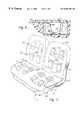
- FIG. 1is a perspective view of a dual vehicle seat unit incorporating a massaging system according to the present invention
- FIG. 2is an enlarged partially exploded perspective view of a cushion portion of the system of FIG. 1;
- FIG. 3is a sectional view of the cushion portion of FIG. 2;
- FIG. 3Ais a sectional view as in FIG. 3, showing a preferred alternative configuration of the cushion portion of FIG. 2;
- FIG. 4is a wiring diagram of the system of FIG. 1;
- FIG. 5is a sectional view as in FIG. 3, showing an alternative configuration of the cushion portion of FIG. 2;
- FIG. 6is a side view showing an alternative configuration of a vibrator portion of the system of FIG. 1;
- FIG. 7is a fragmentary sectional end view of the vibrator portion of FIG. 6;
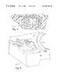
- FIG. 8is a plan view showing an alternative configuration of a seat portion of the system of FIG. 1;
- FIG. 9is an elevational view showing an alternative configuration of a back cushion portion of the system of FIG. 1;
- FIG. 10is an enlarged partially exploded perspective view of a heater of the present invention.
- FIG. 11is a perspective view of an alternative configuration of a seat portion having a motorized structure in the system of the present invention.
- FIG. 12is a sectional view showing an alternative configuration of the cushion portion of the system of the present invention.
- the present inventionis directed to a massaging system that is particularly effective in selectively massaging local muscle groups of a user, while limiting transmission of vibrations to adjacent seating and structure.
- the present inventioncomprises a microcontroller based massaging system 10 that is installed in equipment such as a vehicle, a vehicle floor being designated 11 in FIG. 1 .
- the system 10has a plurality of vibrators 12 that are embedded in a massage pad 14 which can form a portion of a seat 15 .
- FIG. 1shows separate counterparts of the system 10 in a side-by-side pair of seats 15 , the seats 15 being structurally joined as further described below.
- the system 10may also contain embedded heaters 16 such as a seat heater 16 A and a back heater 16 B for enhanced massaging of the user.
- Each vibrator 12has a housing 13 being further described below, and may comprise a conventional combination of a small DC motor that rotates an eccentric weight, or if desired, a pair of eccentrics at opposite ends of the motor, the vibrators 12 being sometimes referred to herein as motors. It will be understood that other forms of vibrators may be used.
- the massage pad 14can be a separate device that is not integrated with the seat 15 .
- the pad 14may be divided into foldable sections such as an upper section being the back pad 14 B (for supporting the upper and lower back of the user), and a lower section being the seat pad 14 A (for supporting the user's hips and thighs). It will be understood that the pad 14 can also include a further section for stimulation and/or massaging of the user's calves.
- each of the vibrators 12is located in a cavity 17 that is formed in a main cushion member 18 of the seat 15 , an isolation device 20 being interposed between the housing 13 and the cushion member 18 for suppressing the coupling of vibrations of the housing 13 to the cushion 18 .
- the cavity 17interrupts a main supporting surface 19 of the cushion 18 .
- An outer cushion member 21is bonded to the main supporting surface 19 , thereby enclosing respective ones of the vibrators 12 and the isolation devices 20 in the cavities 17 .
- a flexible reinforcing sheet member 22is laminated between the main cushion member 18 and the outer cushion member 21 , the sheet member 22 also covering the cavities 17 .
- each housing 13is formed for enhanced coupling of vibrations into the outer cushion member 21 relative to the suppressed coupling to the main cushion member 18 .
- each housing 13is formed (such as by molding) with a generally cylindrical body portion 23 and a generally planar plate portion 24 , the housing 13 being oriented ⁇ with the plate portion 23 facing the outer cushion member 21 in parallel relation thereto.
- the plate portion 24projects beyond opposite sides of the body portion 23 for presenting an enhanced surface area of the plate portion in close proximity to the outer cushion member 21 , a lower portion of the body portion being circularly cylindrical for limited area proximity of the housing 13 with the main cushion member 18 .
- the enhanced coupling by the plate portion 24is obtained when the plate portion projects beyond at least one side of the body portion 23 .
- each housing 13has a length A and a width B of the plate portion, the body portion having a length C and a width corresponding to a diameter D of the bottom portion, the housing 13 also having a depth E approximately corresponding to the diameter D.
- the cavity 17has a length L that exceeds the length A by a distance that is sufficient for accommodating layers of the isolation device 20 at opposite ends of the housing 13 , that distance being preferably between 0.2 inch and 0.5 inch.
- the cavity 17has a width W that exceeds the width B by a corresponding distance, and a depth or height H that exceeds the depth E by a distance that is also preferably between 0.2 inch and 0.5 inch.
- the isolation device 20occupies at least 40 percent of the volume of each cavity 17 . As further shown in FIGS. 2 and 3, a portion of the isolation device 20 extends between the plate portion 24 and the outer cushion member 21 (and the sheet member 22 ).
- Suitable materials for the main cushion member 18 and the outer cushion member 21include conventional closed-cell foam padding such as 2-pound mini-cell polyethylene, the outer cushion member 21 preferably having a uniform thickness T that can be approximately 0.25 inch.
- the massage pad 14has a foam core including the cushion members 18 and 21 .
- the main cushion member 18has a thickness on the order of 2 or 2.5 inches.
- Each massage pad 14also typically has an outer flexible seat cover 25 as shown in FIG. 2, which can be made from a decorative material such as sheepskin fur.
- a suitable material for the isolation device 20is NomexTM batting fiber, available from Skandia of Rockford, Ill.
- a suitable material for the sheet member 22is needle punch polyester Style #330, 8 oz.
- the material of the isolation device 20in a free thickness of approximately 0.5 inch, is wrapped at least partially about each vibrator 12 .
- the isolation device 20completely surrounds the housing 13 , being accordion-folded in regions of the cavity 17 beneath the outwardly projecting portions of the plate portion 24 .
- the isolation member 20can be formed of separate pieces, one being placed into the cavity 17 prior to insertion of the vibrator 12 , the other being wrapped over upper and lower surfaces of the plate portion 24 .
- the sheet member 22is first bonded to the outer cushion member 21 by a suitable adhesive such as a spray foam adhesive and, after the vibrators 12 and the isolation devices 20 are in place, the combination of the members 21 and 22 is bonded to the supporting surface 19 of the main cushion member 18 by a further quantity of the adhesive.
- a suitable spray adhesiveis Super 77TM Spray Adhesive, available from Minnesota Mining and Manufacturing Corp. of St. Paul, Minn.
- each vibrator housing 13can be bonded directly to the sheet member 22 instead of having the isolation device 20 interposed therebetween.
- the bonding of plural vibrators 12 to the outer cushion member 21 (and the sheet member 22 )provides an inexpensive way to produce a subassembly that greatly facilitates fabrication of the massaging system 10 in many applications.
- a preferred method for fabricating the massage pad 14includes forming the main cushion member 18 with a spaced plurality of the cavities 17 in the main supporting surface, bonding the vibrators 12 to the outer cushion member 21 with spacing corresponding to the spacing of the cavities 17 , inserting the isolation devices 20 into the cavities 17 , and bonding the outer cushion member to the supporting surface 19 of the main cushion member 18 .
- the vibrators 12 and the outer cushion member 21can be provided as inexpensive subassemblies (with the sheet member 22 and/or the heater 16 ) for use in retrofitting existing seating with the system 10 as described below as well as for facilitating production of new equipment as described above.
- an alternative and preferred configuration of the isolation device, designated 20 ′has counterparts of the previously described fibrous device 20 (FIG. 3) confined below the plate portion 24 , the housing 13 directly contacting the sheet member 22 , and a separate foam member, designated conformal pad 34 , filling a bottom portion of the cavity 17 .
- the pad 34contacts and conforms to the shape of the bottom portion of the housing bottom portion 23 .
- a suitable material for the conformal pad 34is available as No. CF-40 Confor Foam from Skandia.
- the pads 14collectively have eight vibrators 12 arranged in groups of two motors in four zones, as follows: (1) a first zone 26 for the left and right sides of the shoulder area; a second zone 28 for the left and right sides of the lower back; a third zone 30 for the left and right hips; and a fourth zone 32 for the left and right thighs.
- the seat heater 16 Ais centrally located between the hip and thigh areas 30 and 32
- the back heater 16 Bis centrally located in or between the shoulder and lower back areas 26 and 28 . It will be understood that other groupings and numbers of zones are contemplated.
- the system 10is activated via a remote control device or wand 36 containing push buttons or keys and visual status indicators, as more fully described in copending U.S. patent application Ser. No. 09/081,402 that was filed on May 18, 1998, and which is incorporated herein by this reference.
- the wand 36is removably coupled to an electronics module 37 via a cable 38 , the module 37 having a programmed microcontroller (MCU) 111 for driving the vibrators 12 and heaters 16 as described in the above-referenced patent application.
- MCUprogrammed microcontroller
- the electronics module 37is mounted under the seat pad 14 A, being electrically connected to the vibrators 12 and the heaters 16 by separate wiring harnesses 39 , designated seat harness 39 A and back harness 39 B as indicated in FIG.
- control wand 36provides a variety of functions or modes which are performed through the manipulation of buttons, keys or equivalent means, with corresponding indicators that designate selected functions and modes as further described in the above-referenced copending patent application. It will be understood that some or all of the control functions of the MCU 111 can be incorporated in the wand 36 . Further, the wand 36 can built into an arm of the seat 15 instead of being a hand-held unit as shown in FIG. 1 .
- each vibrator 12is caused to vibrate as the eccentric weight rotates, thereby deforming primarily selected regions of the outer pad member 21 and coupling the vibrations for stimulating and/or massaging muscle tissue of the user.
- a “PWR” button on the wand 36the PWR button also acting as a double action key for selecting massage duration, and optionally entering test and demonstration modes.
- the four zones 26 - 32are individually actuable by pressing corresponding buttons, with visual status indications being provided by respective lights disposed adjacent the buttons.
- Other buttonscontrol the heaters 16 and various modes of operation of the vibrators 12 , such as select, wave, pulse and zig-zag massaging modes. Additional buttons can control intensity and the speed of progression of the various modes. Additional optional features and modes are described in commonly owned copending application Ser. No. 09/071,357, entitled Microcontroller Based Massage System, that was filed on Apr. 28, 1998, being incorporated herein by this reference.
- the side-by-side pair of seats 15have a structural support in the form of a leg frame 42 that is shared between adjacent ones of the seats 15 , additional structure (not shown) connecting the frame 42 beneath and/or within the massage pads 14 .
- the frame 42is suitably secured to the vehicle floor 11 , and may incorporate a positioning mechanism (not shown).
- the isolation deviceprovides fluidic viscous damping of vibrations within the cavity 17 opposite the vibrator 12 from the outer cushion member 21 .
- the device 20 ′includes a bag or envelope member 44 sealingly enclosing a highly viscous gel material 45 .
- the envelope member 44can be a conventional polymer bag having a sealable opening.
- a particularly preferred configuration of the envelope member 45is generally torroidal, having a central opening 44 ′ into which the body portion 23 of the vibrator 12 projects.
- a suitable source of the gel material 45is commercially available as minicyclinder pad filler formula #9001-01 from Gar Labs of Riverside, Calif.
- each vibrator 12can have a counterpart of the housing, designated 13 ′, wherein the body portion 23 is formed by a U-shaped sheet metal holder 48 , the plate portion 24 being formed by a molded plate member 50 , outwardly projecting tab portions 52 of the holder 48 engaging respective pockets 54 that are formed in the plate member 50 .
- a motor 56 having an eccentric mass 58is retained between the holder 48 and the plate 50 , the housing 13 ′ further including a cap member 60 for insuring that fibers of the isolation member 20 are prevented from coming into contact with the eccentric mass 58 .
- an alternative configuration of the massaging system 10has provisions for wiring to the vibrators 12 passing laterally from the cavities 17 and around side extremities of the main cushion members 18 to locations opposite the supporting surfaces 19 .
- a passage or slot 62is cut from each cavity 17 to a depth of approximately 0.5 inch for receiving respective pairs of conductors of the corresponding wiring harness 39 .
- the conductorsare dressed into the slots 62 , which are then sealed shut using a suitable adhesive, such as the above-identified spray adhesive.
- FIGS. 8 and 9also show an exemplary and preferred arrangement of the cavities 17 in the seat pad 14 A and the back cushion 14 B.
- one pair of the cavities 17(for the hips zone, 30 ) is centered at a distance K from a rear extremity of the pad 14 A, another pair of the cavities (for the thighs zone 32 ) being spaced forwardly a distance L beyond the distance K as shown in FIG. 8 .
- the cavities 17 for the thighs zone 32are laterally spaced laterally by a center distance M, the cavities 17 for the hips zone 30 being spaced laterally by a distance N that is preferably less than the distance M.
- one pair of the cavities 17(for the lower back zone 28 ) is centered at a distance P from a bottom extremity of the pad 14 B, another pair of the cavities (for the upper back zone 32 ) being spaced upwardly a distance Q beyond the distance P as shown in FIG. 9 .
- the cavities 17 for the upper and lower back zones 26 and 28are laterally spaced laterally by a center distance R.
- Preferred locations for the heaters 16 A and 16 Bare further indicated by broken lines in FIGS. 8 and 9. More particularly, the heater 16 A is laterally centered within the distance K and partially covering the cavities 17 for the hips zone 30 as shown in FIG. 8 . The heater 16 A is laterally centered within the distance K and partially covering the cavities 17 for the hips zone 30 as shown in FIG. 8 . The heater 16 B is laterally centered in the lumbar area, covering the cavities 17 of the lower back zone 28 . Counterparts of the slots 62 can be cut into the combination of the main and outer cushion member as indicated at 64 for receiving conductors of the harnesses 39 being connected to the heaters 16 .
- each heater 16has a thermostat element 72 wired thereto, a short slit opening having a depth of approximately 1 inch being cut through the outer cushion member 21 for receiving the thermostat element 72 .
- the slit and the slot 64 for each of the heaters 16are also adhesively sealed as described above once the wiring is in place.
- a preferred configuration of the heaters 16that provides exemplary fire resistance without excessively interfering with massaging action includes a pair of sheet members 74 having an adhesive film coating 76 on one side thereof, and a nominally planar assembly of a resistance wire 78 and the thermostat element 72 that is adhesively sandwiched between the sheet members 74 .
- a suitable material for the sheet members 74is a bum-resistant polyamide film, one such material being available as bum resistant Kapton® from DuPont of Wimington, Del. and having a burn resistant silicone-based contact cement coated on one side thereof.
- Electrical power for each heater 16is delivered through a two-conductor electrical cable 80 that enters between the sheet members 74 , being connected, respectively to the resistance wire 76 and the (series-connected) thermostat element 72 by crimped connections 82 , an additional crimped connection 82 being made at the previously described series connection between the wire 76 and the thermostat element 78 .
- the connection 82 between the thermostat element 72 and the cable 80is covered by length of shrink tubing 83 ,
- a first one of the sheet members, designated 74 Ahas its adhesive coating facing away from the sandwiched wiring and temporarily having a release film 84 thereon, the film 84 being removed just prior to bonding to the outer cushion member 21 .
- the other sheet memberdesignated 74 B, has its adhesive coating facing inwardly for bonding to the wiring and the first sheet member 74 A. Also shown in FIG. 10 are lengths of adhesive Kapton® tape 85 for holding the wire 78 onto the first sheet member 74 A and restraining movement of the wire 78 .
- a suitable cable for the electrical cable 80 having burn resistant insulationis available according to MIL-W-227500-20TE 2U00 from A. E. Petshe, of Costa Mesa, Calif.
- suitable soldered connectionsmay be substituted for the crimped connections 82 .
- each of the sheet members 74has a thickness of approximately 0.002 inch for providing sufficient structural integrity while effectively transmitting vibrations from the vibrator 12 to an occupant of the seat 15 .
- a method for converting a padded support device to produce isolated massaging of a user's bodyincludes steps of:
- the seat 15can include a motorized structure 86 for modifying a contour of the massage pad 14 , such structure being commercially available as a Model “N” 4-way electrical lumbar unit from Schukra Division of Legget and Platt Company located in Ontario, Canada.
- the structure 86extends sufficiently close to the front of the pad 14 to preclude location of the previously described vibrators 12 therebetween.
- the vibrator 12 for that locationis configured with the housing 13 ′′, the plate portion 24 thereof extending between the outer cushion 21 and the structure 86 , the body portion 23 being displaced laterally relative to the plate portion 24 for clearing the structure 86 .
- the pad 14can include counterparts of the main cushion member 18 with the cavity 17 formed therein, and the outer cushion 21 , the cavity 17 having an offset configuration for accommodating the offset housing 13 ′′ and a counterpart of the isolation device 20 ′′ of FIG. 5 as shown in FIG. 12 .
- the envelope member 44can be formed with the preferred opening 44 ′ of FIG. 5, not shown in FIG. 12 .
- system 10 of the present inventionis effective for both improving the selectivity of massaging action as well as for preventing unwanted vibrations being conducted into adjacent seating or other structure.
- the sheet member 22is not required to completely cover the supportive surface 19 .
- the sheet membercan be sufficiently large to extend some distance beyond opposite sides of the cavities 17 of the corresponding massage pad 14 ; alternatively, smaller pieces of the material can be used to cover pairs of the cavities or, if the cavities are sufficiently spaced, single pieces of the sheet material can be bonded over individual ones of the cavities 17 .
- one or both of the heaters 16can be bonded to the sheet member 22 , either in facing relation to the main cushion member 18 or to the outer cushion member 21 , prior to the bonding to the supporting surface 19 .
- the heater 16can serve as a reinforcing closure of at least some of the cavities 17 , replacing some or all of the sheet member 22 . Therefore, the spirit and scope of the appended claims should not necessarily be limited to the description of the preferred versions contained herein.
Landscapes
- Engineering & Computer Science (AREA)
- Health & Medical Sciences (AREA)
- Aviation & Aerospace Engineering (AREA)
- Transportation (AREA)
- Mechanical Engineering (AREA)
- Physical Education & Sports Medicine (AREA)
- Epidemiology (AREA)
- Pain & Pain Management (AREA)
- Human Computer Interaction (AREA)
- Rehabilitation Therapy (AREA)
- Life Sciences & Earth Sciences (AREA)
- Animal Behavior & Ethology (AREA)
- General Health & Medical Sciences (AREA)
- Public Health (AREA)
- Veterinary Medicine (AREA)
- Percussion Or Vibration Massage (AREA)
Abstract
Description
The present invention relates to massaging devices, and more particularly to massaging systems to be used in vehicles and other environments where radiated vibrations may be objectionable, such as in multiple seating structures and the like.
Typical massaging systems of the prior art include multiple vibrators that are imbedded in cushions or pads of beds, lounges, chairs and the like. See, for example, U.S. Pat. No. 5,188,096 to Yoo and U.S. Pat. No. 5,429,585 to Liang. It is also known to incorporate massaging vibrators in vehicle seats as disclosed in U.S. Pat. No. 5,462,515 to Tseng. A problem with these systems is that when there are multiple occupants, vibrators activated for the benefit of one occupant transmit significant and often objectionable vibrations to other occupants through shared padding and/or common structural elements. Although individual bucket seats are in common use by drivers and front seat passengers, they are less commonly provided for other passengers of automobiles and other vehicles. Accordingly, it has heretofore been impractical to provide bench seats of automobiles and passenger seats of aircraft with massaging systems.
Another problem is that users of massagers having pad-imbedded vibrators sometimes desire localized massaging only. However, the vibrations are transmitted with only gradual attenuation generally throughout the pad. Thus users are faced with the unwelcome choice of avoiding contact between the pad and particular body parts or putting up with unwanted vibrations.
A further problem is that internal structure of many seats interferes with a desired placement of vibration sources, rendering impractical desired patterns and modes of massaging.
It is also known to provide heating elements in combination with massaging devices of seats. However, existing heating elements of the prior art that are compatible with massaging can present objectionable fire hazards in some applications such as in aircraft seating.
Thus there is a need for a massaging system that overcomes the disadvantages of the prior art.
The present invention provides a massaging system having localized massaging action. The motors are embedded in a padded user support, such as a vehicle seat, in a manner that avoids transmission of vibrations into structural members or non-local foam, and adjacent seating, if present. In one aspect of the invention, a massaging system for an occupant support structure includes a vibrator unit located in the support structure; a controller circuit for selectively powering the vibrator unit for selectively stimulating an occupant of the structure, the vibrator unit being in a cavity of a main cushion member, the cavity being closed by an outer cushion member that supports the occupant, a flexible isolation device being interposed between the vibrator unit and the main cushion member for isolating vibrations from the main cushion member. Preferably the isolation device comprises a viscous material for damping vibrations being radiated toward the main cushion member from the vibrator unit. The isolation device can incorporate the viscous material within a flexible sealed enclosure. Preferably the enclosure has an opening formed between opposite sides thereof for receiving a body portion of the vibrator unit. Alternatively, the isolation device can be formed of a material having a bulk or volumetric stiffness being less than corresponding stiffnesses of the main and outer cushion members.
A housing of the vibrator unit can have a generally cylindrical body portion and a plate portion, the plate portion facing the outer cushion member in generally parallel relation thereto. Preferably the plate portion is affixed to the outer cushion member for enhanced coupling of vibrations to the outer cushion member while maintaining the isolation from the main cushion member. The plate portion can project beyond opposite sides of the body portion. The plate portion can project beyond opposite ends of the body portion. A lower portion of the housing body portion can be circularly cylindrical, having an outside diameter D, the housing also having a depth approximately corresponding to the diameter D in a direction perpendicular to the plate portion.
The plate portion can have a length A and a width B, the cavity having a length L and a width W, the width W being between 0.2 inch and 0.5 inch greater than the width B, the length L being between 0.2 inch and 0.5 inch greater than the length A. The housing can have a depth E, the cavity having a height H, the height H being between 0.2 inch and 0.5 inch greater than the depth E. The length L can be approximately 3.75 inch, the width W being approximately 2.75 inch. The height H can be approximately 1.5 inch. Preferably the isolation device occupies at least 40 percent of an overall volume of the cavity for enhancing the effectiveness of the vibration isolation.
The apparatus can further include a reinforcing sheet member laminated between the main cushion member and the outer cushion member. The outer cushion member can be of substantially uniform thickness. The thickness of the outer cushion member can be between 0.18 inch and 0.4 inch. Preferably the thickness of the outer cushion member is approximately 0.25 inch.
Preferably the vibrator unit is one of a spaced plurality of vibrators that are located in plural zones of the structure for selectively stimulating particular tissue regions of the occupant, each vibrator being located in a corresponding counterpart of the cavity and having a corresponding isolation device interposed between the housing and the cavity. The outer cushion can cover each of the cavities. The main cushion and the outer cushion can form a seat pad of a seat. The massaging apparatus can be in combination with a back pad of the seat, the back pad having counterparts of the vibrators, the main cushion, the isolation devices, and the outer cushion. The seat can be one of a plurality of seats having a common structural element.
The apparatus can further include a heater unit attached to the outer cushion member and having a resistance wire connected between conductors of a fire resistant power cord and, secured between a pair of polyamide film sheet members, one side of each sheet member having a silicon base fire resistant adhesive coating, of the adhesive coating of one sheet member contacting the resistance wire and the other sheet member, the coating of the other sheet member securing the heater unit to the outer cushion member. Preferably the thickness of each sheet member is approximately 0.002 inch for providing sufficient structural integrity while effectively transmitting vibrations from the vibrator to a user having contact with the apparatus proximate the heater unit.
In another aspect of the invention, a vehicle seat includes a structural member and respective seat and back pads supported relative thereto, each pad a plurality of vibrator units, each vibrator unit having a housing, a motor supported within the housing, and means for connecting the motor to a source of electrical power, the motor being coupled to a mass element for producing vibratory motion of the housing; a main cushion member having a main supporting surface and having a plurality of spaced apart cavities formed therein and interrupting the supporting surface for receiving respective ones of the vibrator units, each cavity being sufficiently large to provide clearance space on all sides of the corresponding vibrator unit; a plurality of isolation devices in respective ones of the cavities; and an outer cushion member with the vibrators bonded thereto and projecting into respective cavities of the main cushion member, the outer cushion member being also bonded to the main supporting surface and covering the cavities with each isolation device contacting a bottom portion of a vibrator unit and being interposed between the vibrator unit and the main cushion member for coupling vibrations mainly into the outer cushion member, the outer cushion member forming an outer supporting surface being spaced from the main supporting surface. The massaging apparatus can further include a controller electrically connected to each of the vibrators for activating selected ones of the vibrators. Each of the isolation devices can include the flexible sealed enclosure having a viscous material contained therein.
In another aspect of the invention, a seat includes a structural member, a pad supported relative to the structural member with the structural member extending behind a target region zone of an occupant supporting surface of the pad; a vibrator unit having a housing including a projecting plate portion, a motor supported within the housing, means for connecting the motor to a source of electrical power, the motor being coupled to a mass element for producing vibratory motion of the housing, the vibrator unit being supported by the pad with the plate portion extending between the structural member and the target region zone for imparting vibrations to the occupant supporting surface opposite the structural member, the body portion of the housing projecting away from the occupant supporting surface at one side of the structural member.
In another aspect of the invention, a massaging apparatus includes a vibrator unit having a housing including a body portion and a plate portion that projects from one side by a distance greater than a width of the body portion, a main cushion member having a main supporting surface and being formed of a resilient material, a cavity interrupting the supporting surface being formed therein; a structure supporting the main cushion member with a structural member extending parallel to the main supporting surface for modifying its contour; and an outer cushion member bonded to the main supporting surface and covering the cavity, the outer cushion member forming the outer supporting surface spaced from the main supporting surface, the cushion members a seat pad of a seat that also includes a structural member extending within the pad in relatively closely spaced relation to a target zone region of the outer supporting surface, the vibrator being located within the cavity with the plate portion of the housing facing a target zone region of the outer cushion member in generally parallel relation thereto, the plate portion projecting between the structural member and the outer cushion member for imparting vibrations through the outer cushion member opposite the structural member, the body portion of the housing projecting away from the outer cushion member at one side of the structural member. The cavity can be configured to provide clearance space on all sides of the vibrator unit, the apparatus further including the isolation device contacting the vibrator and being interposed between the vibrator and the main cushion member.
In a further aspect of the invention, a method for converting a padded support device having a resilient main cushion to produce isolated massaging of a user's body includes:
(a) providing a vibratory transducer having a housing and a control cable extending from the housing for driving the transducer;
(b) forming a cavity in a supporting surface of the main cushion, the cavity being sufficiently large for receiving the transducer housing in spaced relation to the main cushion;
(c) placing the transducer housing in the cavity;
(d) positioning the control cable to extend from the cavity and on the supporting surface to an edge margin thereof;
(e) interposing a resilient isolation device between the transducer housing and the main cushion member with a portion of the housing contacting and projecting into the isolation device;
(f) providing a resilient pad member for covering the supporting surface;
(g) bonding a reinforcing sheet member to a bottom surface of the pad member; and
(h) bonding the sheet member to the supporting surface, the sheet member being laminated between the main cushion and the pad member and covering the cavity.
The step of enclosing can include completely. enclosing the transducer housing with the isolation material, the isolation material preferably having a volume of not less than 40 percent of a volume of the cavity. Alternatively, the placing and enclosing includes fastening the transducer onto the sheet member in fixed relation to the pad member prior to bonding the sheet member to the supporting surface. Further, there be a plurality of the transducers, the forming being of a corresponding plurality of spaced apart cavities, and the fastening including spacing the transducer on the sheet member in correspondence with the spacing of the cavities.
These and other features, aspects, and advantages of the present invention will become better understood with reference to the following description, appended claims, and accompanying drawings, where:
FIG. 1 is a perspective view of a dual vehicle seat unit incorporating a massaging system according to the present invention;
FIG. 2 is an enlarged partially exploded perspective view of a cushion portion of the system of FIG. 1;
FIG. 3 is a sectional view of the cushion portion of FIG. 2;
FIG. 3A is a sectional view as in FIG. 3, showing a preferred alternative configuration of the cushion portion of FIG. 2;
FIG. 4 is a wiring diagram of the system of FIG. 1;
FIG. 5 is a sectional view as in FIG. 3, showing an alternative configuration of the cushion portion of FIG. 2;
FIG. 6 is a side view showing an alternative configuration of a vibrator portion of the system of FIG. 1;
FIG. 7 is a fragmentary sectional end view of the vibrator portion of FIG. 6;
FIG. 8 is a plan view showing an alternative configuration of a seat portion of the system of FIG. 1;
FIG. 9 is an elevational view showing an alternative configuration of a back cushion portion of the system of FIG. 1;
FIG. 10 is an enlarged partially exploded perspective view of a heater of the present invention;
FIG. 11 is a perspective view of an alternative configuration of a seat portion having a motorized structure in the system of the present invention; and
FIG. 12 is a sectional view showing an alternative configuration of the cushion portion of the system of the present invention.
The present invention is directed to a massaging system that is particularly effective in selectively massaging local muscle groups of a user, while limiting transmission of vibrations to adjacent seating and structure. With reference to FIGS. 1-4 of the drawings, the present invention comprises a microcontroller based massagingsystem 10 that is installed in equipment such as a vehicle, a vehicle floor being designated11 in FIG.1. Thesystem 10 has a plurality ofvibrators 12 that are embedded in amassage pad 14 which can form a portion of aseat 15. FIG. 1 shows separate counterparts of thesystem 10 in a side-by-side pair ofseats 15, theseats 15 being structurally joined as further described below. In theexemplary seat 15, there is aseat cushion 14A and aseparate back cushion 14B. Thesystem 10 may also contain embeddedheaters 16 such as aseat heater 16A and a back heater16B for enhanced massaging of the user. Eachvibrator 12 has ahousing 13 being further described below, and may comprise a conventional combination of a small DC motor that rotates an eccentric weight, or if desired, a pair of eccentrics at opposite ends of the motor, thevibrators 12 being sometimes referred to herein as motors. It will be understood that other forms of vibrators may be used. Also, themassage pad 14 can be a separate device that is not integrated with theseat 15. Thepad 14 may be divided into foldable sections such as an upper section being theback pad 14B (for supporting the upper and lower back of the user), and a lower section being theseat pad 14A (for supporting the user's hips and thighs). It will be understood that thepad 14 can also include a further section for stimulation and/or massaging of the user's calves.
According to the present invention, each of thevibrators 12 is located in acavity 17 that is formed in amain cushion member 18 of theseat 15, anisolation device 20 being interposed between thehousing 13 and thecushion member 18 for suppressing the coupling of vibrations of thehousing 13 to thecushion 18. Thecavity 17 interrupts a main supportingsurface 19 of thecushion 18. Anouter cushion member 21 is bonded to the main supportingsurface 19, thereby enclosing respective ones of thevibrators 12 and theisolation devices 20 in thecavities 17. Preferably a flexible reinforcingsheet member 22 is laminated between themain cushion member 18 and theouter cushion member 21, thesheet member 22 also covering thecavities 17. Preferably, thehousing 13 is formed for enhanced coupling of vibrations into theouter cushion member 21 relative to the suppressed coupling to themain cushion member 18. Accordingly, eachhousing 13 is formed (such as by molding) with a generallycylindrical body portion 23 and a generallyplanar plate portion 24, thehousing 13 being oriented~with theplate portion 23 facing theouter cushion member 21 in parallel relation thereto. As shown in FIG. 3, theplate portion 24 projects beyond opposite sides of thebody portion 23 for presenting an enhanced surface area of the plate portion in close proximity to theouter cushion member 21, a lower portion of the body portion being circularly cylindrical for limited area proximity of thehousing 13 with themain cushion member 18. It will be understood that the enhanced coupling by theplate portion 24 is obtained when the plate portion projects beyond at least one side of thebody portion 23.
Theplate portion 24 can also project beyond opposite ends of thebody portion 23 as further shown in FIG.1. More particularly, eachhousing 13 has a length A and a width B of the plate portion, the body portion having a length C and a width corresponding to a diameter D of the bottom portion, thehousing 13 also having a depth E approximately corresponding to the diameter D. Thecavity 17 has a length L that exceeds the length A by a distance that is sufficient for accommodating layers of theisolation device 20 at opposite ends of thehousing 13, that distance being preferably between 0.2 inch and 0.5 inch. Also, thecavity 17 has a width W that exceeds the width B by a corresponding distance, and a depth or height H that exceeds the depth E by a distance that is also preferably between 0.2 inch and 0.5 inch. In an exemplary configuration of thesystem 10, the approximate dimensions of thehousing 13 are A=3.5 inches, B=2.5 inches, C=2.0 inches, D=1.15 inches, and E=1.19 inches; the approximate dimensions of thecavity 17 being L=3.75 inches, W=2.75 inches, and H=1.5 inches. Corner extremities of thecavity 17 are rounded, having a corner radius which can be approximately 0.4 inch, theplate portion 24 of thehousing 13 correspondingly having a corner radius (which can be approximately 0.2 inch) as shown in FIG. 2 for maintaining clearance between thevibrator 12 and themain cushion member 18. Preferably, theisolation device 20 occupies at least 40 percent of the volume of eachcavity 17. As further shown in FIGS. 2 and 3, a portion of theisolation device 20 extends between theplate portion 24 and the outer cushion member21 (and the sheet member22).
Suitable materials for themain cushion member 18 and theouter cushion member 21 include conventional closed-cell foam padding such as 2-pound mini-cell polyethylene, theouter cushion member 21 preferably having a uniform thickness T that can be approximately 0.25 inch. Thus themassage pad 14 has a foam core including thecushion members main cushion member 18 has a thickness on the order of 2 or 2.5 inches. Eachmassage pad 14 also typically has an outer flexible seat cover25 as shown in FIG. 2, which can be made from a decorative material such as sheepskin fur. A suitable material for theisolation device 20 is Nomex™ batting fiber, available from Skandia of Rockford, Ill. A suitable material for thesheet member 22 is needle punchpolyester Style # 330, 8 oz. denier fiber, available from Lily Designs of Glendale, Calif. The material of theisolation device 20, in a free thickness of approximately 0.5 inch, is wrapped at least partially about eachvibrator 12. In the exemplary configuration of FIGS. 1-3, theisolation device 20 completely surrounds thehousing 13, being accordion-folded in regions of thecavity 17 beneath the outwardly projecting portions of theplate portion 24. As further shown in FIG. 3, theisolation member 20 can be formed of separate pieces, one being placed into thecavity 17 prior to insertion of thevibrator 12, the other being wrapped over upper and lower surfaces of theplate portion 24. Thesheet member 22 is first bonded to theouter cushion member 21 by a suitable adhesive such as a spray foam adhesive and, after thevibrators 12 and theisolation devices 20 are in place, the combination of themembers surface 19 of themain cushion member 18 by a further quantity of the adhesive. A suitable spray adhesive is Super 77™ Spray Adhesive, available from Minnesota Mining and Manufacturing Corp. of St. Paul, Minn. When apad 14 is provided with aheater 16, the heater is bonded to theouter cushion member 21 opposite thesheet member 22, being covered by the seat cover25, which can also be bonded to thecushion member 21 and theheater 16.
With further reference to FIG. 3A, theplate portion 24 of eachvibrator housing 13 can be bonded directly to thesheet member 22 instead of having theisolation device 20 interposed therebetween. In this configuration, there is significantly greater coupling of vibrations into theouter cushion member 21 without greatly increased coupling to themain cushion member 18. Also, the bonding ofplural vibrators 12 to the outer cushion member21 (and the sheet member22) provides an inexpensive way to produce a subassembly that greatly facilitates fabrication of the massagingsystem 10 in many applications. Thus a preferred method for fabricating themassage pad 14 includes forming themain cushion member 18 with a spaced plurality of thecavities 17 in the main supporting surface, bonding thevibrators 12 to theouter cushion member 21 with spacing corresponding to the spacing of thecavities 17, inserting theisolation devices 20 into thecavities 17, and bonding the outer cushion member to the supportingsurface 19 of themain cushion member 18. Thus thevibrators 12 and theouter cushion member 21 can be provided as inexpensive subassemblies (with thesheet member 22 and/or the heater16) for use in retrofitting existing seating with thesystem 10 as described below as well as for facilitating production of new equipment as described above.
As further shown in FIG. 3A, an alternative and preferred configuration of the isolation device, designated20′, has counterparts of the previously described fibrous device20 (FIG. 3) confined below theplate portion 24, thehousing 13 directly contacting thesheet member 22, and a separate foam member, designatedconformal pad 34, filling a bottom portion of thecavity 17. Thepad 34 contacts and conforms to the shape of the bottom portion of thehousing bottom portion 23. A suitable material for theconformal pad 34 is available as No. CF-40 Confor Foam from Skandia.
In the exemplary configuration shown in FIG. 1, thepads 14 collectively have eightvibrators 12 arranged in groups of two motors in four zones, as follows: (1) afirst zone 26 for the left and right sides of the shoulder area; asecond zone 28 for the left and right sides of the lower back; athird zone 30 for the left and right hips; and afourth zone 32 for the left and right thighs. Typically, theseat heater 16A is centrally located between the hip andthigh areas lower back areas
Thesystem 10 is activated via a remote control device orwand 36 containing push buttons or keys and visual status indicators, as more fully described in copending U.S. patent application Ser. No. 09/081,402 that was filed on May 18, 1998, and which is incorporated herein by this reference. Thewand 36 is removably coupled to an electronics module37 via acable 38, the module37 having a programmed microcontroller (MCU)111 for driving thevibrators 12 andheaters 16 as described in the above-referenced patent application. In an exemplary implementation, the electronics module37 is mounted under theseat pad 14A, being electrically connected to thevibrators 12 and theheaters 16 by separate wiring harnesses39, designated seat harness39A andback harness 39B as indicated in FIG. 4, wiring to the individual vibrators12 (and the heaters16) passing between themain cushion member 18 and thesheet member 22 into respective ones of thecavities 17 as shown in FIG.3. Alternatively, passages can be cut into themain cushion member 18 for passing conductors of theharness 39. Similarly, a thermostat of theheater 16 can be imbedded in themain cushion member 18. Thewand 36 and themassage pad 14 are powered through apower cable 40 from a suitable source such as DC power of the vehicle11. In applications wherein electromagnetic interference is a factor (such as the vehicle11 being an aircraft), theharnesses 39 are provided with grounded shielding as indicated at41, and thevibrators 12 can be provided with suitable bypass capacitors. It will be understood that suitable batteries for operating thesystem 10 can be located within thepad 14 or the electronics module37. Thecontrol wand 36 provides a variety of functions or modes which are performed through the manipulation of buttons, keys or equivalent means, with corresponding indicators that designate selected functions and modes as further described in the above-referenced copending patent application. It will be understood that some or all of the control functions of the MCU111 can be incorporated in thewand 36. Further, thewand 36 can built into an arm of theseat 15 instead of being a hand-held unit as shown in FIG.1.
Thus eachvibrator 12 is caused to vibrate as the eccentric weight rotates, thereby deforming primarily selected regions of theouter pad member 21 and coupling the vibrations for stimulating and/or massaging muscle tissue of the user.
As further described in the referenced copending application, power is turned on or off by a “PWR” button on thewand 36, the PWR button also acting as a double action key for selecting massage duration, and optionally entering test and demonstration modes. The four zones26-32 are individually actuable by pressing corresponding buttons, with visual status indications being provided by respective lights disposed adjacent the buttons. Other buttons control theheaters 16 and various modes of operation of thevibrators 12, such as select, wave, pulse and zig-zag massaging modes. Additional buttons can control intensity and the speed of progression of the various modes. Additional optional features and modes are described in commonly owned copending application Ser. No. 09/071,357, entitled Microcontroller Based Massage System, that was filed on Apr. 28, 1998, being incorporated herein by this reference.
As further shown in FIG. 1, the side-by-side pair ofseats 15 have a structural support in the form of a leg frame42 that is shared between adjacent ones of theseats 15, additional structure (not shown) connecting the frame42 beneath and/or within themassage pads 14. Typically, the frame42 is suitably secured to the vehicle floor11, and may incorporate a positioning mechanism (not shown).
With further reference to FIG. 5, a more preferred configuration of the isolation device, designated20″, provides fluidic viscous damping of vibrations within thecavity 17 opposite thevibrator 12 from theouter cushion member 21. More particularly, thedevice 20′ includes a bag orenvelope member 44 sealingly enclosing a highlyviscous gel material 45. Theenvelope member 44 can be a conventional polymer bag having a sealable opening. A particularly preferred configuration of theenvelope member 45 is generally torroidal, having acentral opening 44′ into which thebody portion 23 of thevibrator 12 projects. A suitable source of thegel material 45 is commercially available as minicyclinder pad filler formula #9001-01 from Gar Labs of Riverside, Calif.
With further reference to FIGS. 6 and 7, eachvibrator 12 can have a counterpart of the housing, designated13′, wherein thebody portion 23 is formed by a U-shapedsheet metal holder 48, theplate portion 24 being formed by a moldedplate member 50, outwardly projectingtab portions 52 of theholder 48 engagingrespective pockets 54 that are formed in theplate member 50. Amotor 56 having aneccentric mass 58 is retained between theholder 48 and theplate 50, thehousing 13′ further including acap member 60 for insuring that fibers of theisolation member 20 are prevented from coming into contact with theeccentric mass 58.
With further reference to FIGS. 8 and 9, an alternative configuration of the massagingsystem 10 has provisions for wiring to thevibrators 12 passing laterally from thecavities 17 and around side extremities of themain cushion members 18 to locations opposite the supporting surfaces19. For this purpose, a passage orslot 62 is cut from eachcavity 17 to a depth of approximately 0.5 inch for receiving respective pairs of conductors of the correspondingwiring harness 39. The conductors are dressed into theslots 62, which are then sealed shut using a suitable adhesive, such as the above-identified spray adhesive.
FIGS. 8 and 9 also show an exemplary and preferred arrangement of thecavities 17 in theseat pad 14A and theback cushion 14B. Particularly regarding theseat cushion 14A, one pair of the cavities17 (for the hips zone,30) is centered at a distance K from a rear extremity of thepad 14A, another pair of the cavities (for the thighs zone32) being spaced forwardly a distance L beyond the distance K as shown in FIG.8. Thecavities 17 for thethighs zone 32 are laterally spaced laterally by a center distance M, thecavities 17 for thehips zone 30 being spaced laterally by a distance N that is preferably less than the distance M. Also regarding theback cushion 14B, one pair of the cavities17 (for the lower back zone28) is centered at a distance P from a bottom extremity of thepad 14B, another pair of the cavities (for the upper back zone32) being spaced upwardly a distance Q beyond the distance P as shown in FIG.9. Thecavities 17 for the upper andlower back zones
Preferred locations for theheaters 16A and16B (when present) are further indicated by broken lines in FIGS. 8 and 9. More particularly, theheater 16A is laterally centered within the distance K and partially covering thecavities 17 for thehips zone 30 as shown in FIG.8. Theheater 16A is laterally centered within the distance K and partially covering thecavities 17 for thehips zone 30 as shown in FIG.8. The heater16B is laterally centered in the lumbar area, covering thecavities 17 of thelower back zone 28. Counterparts of theslots 62 can be cut into the combination of the main and outer cushion member as indicated at64 for receiving conductors of theharnesses 39 being connected to theheaters 16. Typically, eachheater 16 has a thermostat element72 wired thereto, a short slit opening having a depth of approximately 1 inch being cut through theouter cushion member 21 for receiving the thermostat element72. The slit and theslot 64 for each of the heaters16 (if present) are also adhesively sealed as described above once the wiring is in place.
With further reference to FIG. 10, a preferred configuration of theheaters 16 that provides exemplary fire resistance without excessively interfering with massaging action includes a pair ofsheet members 74 having anadhesive film coating 76 on one side thereof, and a nominally planar assembly of a resistance wire78 and the thermostat element72 that is adhesively sandwiched between thesheet members 74. A suitable material for thesheet members 74 is a bum-resistant polyamide film, one such material being available as bum resistant Kapton® from DuPont of Wimington, Del. and having a burn resistant silicone-based contact cement coated on one side thereof. Electrical power for eachheater 16 is delivered through a two-conductorelectrical cable 80 that enters between thesheet members 74, being connected, respectively to theresistance wire 76 and the (series-connected) thermostat element72 by crimpedconnections 82, an additional crimpedconnection 82 being made at the previously described series connection between thewire 76 and the thermostat element78. Theconnection 82 between the thermostat element72 and thecable 80 is covered by length ofshrink tubing 83, A first one of the sheet members, designated74A, has its adhesive coating facing away from the sandwiched wiring and temporarily having arelease film 84 thereon, thefilm 84 being removed just prior to bonding to theouter cushion member 21. The other sheet member, designated74B, has its adhesive coating facing inwardly for bonding to the wiring and thefirst sheet member 74A. Also shown in FIG. 10 are lengths of adhesiveKapton® tape 85 for holding the wire78 onto thefirst sheet member 74A and restraining movement of the wire78. A suitable cable for theelectrical cable 80 having burn resistant insulation is available according to MIL-W-227500-20TE 2U00 from A. E. Petshe, of Costa Mesa, Calif. Alternatively, suitable soldered connections may be substituted for the crimpedconnections 82. Preferably each of thesheet members 74 has a thickness of approximately 0.002 inch for providing sufficient structural integrity while effectively transmitting vibrations from thevibrator 12 to an occupant of theseat 15.
Thesystem 10 of the present invention is also applicable to existing seating as described herein. A method for converting a padded support device to produce isolated massaging of a user's body includes steps of:
1. Removing an outer cover of the device if present for exposing a main cushion thereof;
2. Providing a counterpart of thetransducer 12 having conductors of theharness 39 extending therefrom;
3. Forming a counterpart of thecavity 17 in the main cushion, the cavity interrupting a user-supporting surface of the cushion and being sufficiently large for receiving the combination of thetransducer 12 and theisolation device 20;
5. Providing theisolation device 20;
4. Placing the transducer together with theisolation device 20 in thecavity 17;
6. Positioning the harness to extend from the cavity to an edge margin of the cushion;
7. Providing a counterpart of theouter cushion member 21 for covering the supporting surface;
8. Bonding a counterpart of the reinforcingsheet member 22 to a bottom surface of the outer cushion member; and
9. Bonding the sheet member to the supporting surface with the housing mechanically coupled to the outer cushion member, the sheet member being laminated between the main cushion and the outer cushion member and covering thecavity 17.
With further reference to FIGS. 11 and 12, another alternative configuration of the vibrator housing, designated13″, has theplate portion 24 enlarged and offset to one side of thebody portion 23 for permitting effective massaging in regions of theseat 15 having structure thereof that would block proper placement of thevibrators 12 of FIGS.3 and5-7. As shown in FIG. 11, theseat 15 can include amotorized structure 86 for modifying a contour of themassage pad 14, such structure being commercially available as a Model “N” 4-way electrical lumbar unit from Schukra Division of Legget and Platt Company located in Ontario, Canada. In typical installations, thestructure 86 extends sufficiently close to the front of thepad 14 to preclude location of the previously describedvibrators 12 therebetween. When it is desired to provide effective massaging action in a target region of theseat 15 having such structure, thevibrator 12 for that location is configured with thehousing 13″, theplate portion 24 thereof extending between theouter cushion 21 and thestructure 86, thebody portion 23 being displaced laterally relative to theplate portion 24 for clearing thestructure 86. Optionally, thepad 14 can include counterparts of themain cushion member 18 with thecavity 17 formed therein, and theouter cushion 21, thecavity 17 having an offset configuration for accommodating the offsethousing 13″ and a counterpart of theisolation device 20″ of FIG. 5 as shown in FIG.12. It will be understood that theenvelope member 44 can be formed with thepreferred opening 44′ of FIG. 5, not shown in FIG.12.
Thus it is believed that thesystem 10 of the present invention is effective for both improving the selectivity of massaging action as well as for preventing unwanted vibrations being conducted into adjacent seating or other structure.
Although the present invention has been described in considerable detail with reference to certain preferred versions thereof, other versions are possible. For example, thesheet member 22 is not required to completely cover thesupportive surface 19. Instead, the sheet member can be sufficiently large to extend some distance beyond opposite sides of thecavities 17 of thecorresponding massage pad 14; alternatively, smaller pieces of the material can be used to cover pairs of the cavities or, if the cavities are sufficiently spaced, single pieces of the sheet material can be bonded over individual ones of thecavities 17. Also, one or both of theheaters 16 can be bonded to thesheet member 22, either in facing relation to themain cushion member 18 or to theouter cushion member 21, prior to the bonding to the supportingsurface 19. Moreover, theheater 16 can serve as a reinforcing closure of at least some of thecavities 17, replacing some or all of thesheet member 22. Therefore, the spirit and scope of the appended claims should not necessarily be limited to the description of the preferred versions contained herein.
Claims (34)
1. A massaging apparatus comprising:
(a) a vibrator unit including a housing, a motor supported within the housing, means for connecting the motor to a source of electrical power, the motor being coupled to a mass element for producing vibratory motion of the housing;
(b) a main cushion member having a maim supporting surface and being formed of a resilient material having a first volumetric stiffness, a cavity being formed therein and interrupting the supporting surface for receiving the vibrator unit, the cavity being sufficiently large to provide clearance space on all sides of the vibrator unit;
(c) an isolation device having, a second volumetric stiffness contacting at least a portion of the vibrator unit, the isolation device further contacting at least a portion of the main cushion member, wherein the isolation device is interposed between the vibrator unit and the main cushion member; and
(d) an outer cushion member having a third volumetric stiffness being greater than the second volumetric stiffness, the outer cushion member being bonded to the main supporting surface and covering the cavity, the outer cushion member forming an outer supporting surface being spaced from the main supporting surface.
2. The massaging apparatus ofclaim 1 , wherein the isolation device comprises a viscous material for damping vibrations being radiated toward the main cushion member from the vibrator unit.
3. The massaging apparatus ofclaim 2 , wherein the isolation device incorporates the viscous material within a flexible sealed enclosure.
4. The massaging apparatus ofclaim 3 , wherein the flexible sealed enclosure is formed having an opening between opposite sides thereof for receiving a body portion of the vibrator unit.
5. The massaging apparatus ofclaim 1 , wherein the isolation device has a volumetric stiffness being less than respective volumetric stiffness characteristics of the main and outer cushion members.
6. The massaging apparatus ofclaim 1 , wherein the vibrator housing has a generally cylindrical body portion and a plate portion, the plate portion facing the outer cushion member in generally parallel relation thereto.
7. The massaging apparatus ofclaim 6 , wherein the plate portion of the housing is fixedly connected to the outer cushion member.
8. The massaging apparatus ofclaim 6 , wherein the plate portion projects beyond opposite sides of the body portion.
9. The massaging apparatus ofclaim 8 , wherein the plate portion projects beyond opposite ends of the body portion.
10. The massaging apparatus ofclaim 6 , wherein a lower portion of the housing body portion is circularly cylindrical, having an outside diameter D, the housing also having a depth approximately corresponding to the diameter D in a direction perpendicular to the plate portion.
11. The massaging apparatus ofclaim 6 , wherein the plate portion has a length A and a width B, and the cavity has a length L and a width W, the width W being between 0.2 inch and 0.5 inch greater than the width B, the length L being between 0.2 inch and 0.5 inch greater than the length A.
12. The massaging apparatus ofclaim 11 , wherein the housing has a depth E and the cavity has a height H, the height H being between 0.2 inch and 0.5 inch greater than the depth E.
13. The massaging apparatus ofclaim 11 , wherein the Length L is approximately 3.75 inch and the width W is approximately 2.75 inch.
14. The massaging apparatus ofclaim 13 , wherein the height H is approximately 1.5 inch.
15. The massaging apparatus ofclaim 6 , wherein the isolation device occupies at least 40 percent of an overall volume of the cavity.
16. The massaging apparatus ofclaim 1 , further comprising a reinforcing sheet member laminated between the main cushion member and the outer cushion member.
17. The massaging apparatus ofclaim 16 , wherein the outer cushion member is of substantially uniform thickness.
18. The massaging apparatus ofclaim 17 , wherein the thickness of the outer cushion member is between 0.18 inch and 0.4 inch.
19. The massaging apparatus ofclaim 17 , wherein the thickness of the outer cushion member is approximately 0.25 inch.
20. The massaging apparatus ofclaim 1 , wherein the vibrator is one of a spaced plurality of vibrators, each vibrator being located in a corresponding counterpart of the cavity and having a corresponding isolation device interposed between the housing and the cavity.
21. The massaging apparatus ofclaim 20 , wherein the outer cushion covers each of the cavities.
22. The massaging apparatus ofclaim 20 , wherein the main cushion and the outer cushion form a seat pad of a seat.
23. The massaging apparatus ofclaim 22 , in combination with a back pad of the seat, the back pad having counterparts of the vibrators, the main cushion, the isolation devices, and the outer cushion.
24. The massaging apparatus ofclaim 22 , wherein the seat is one of a plurality of seats having a common structural element.
25. The massaging apparatus ofclaim 1 , further comprising a heater unit fixably connected to the outer cushion member, the heater unit comprising:
(a) a first sheet member having a silicon base fire-resistant adhesive coating on one side thereof for affixing the first sheet member to the outer cushion member;
(b) a resistance wire disposed on the first sheet member opposite the adhesive coating thereof for forming a heater element;
(c) a second sheet member having a silicon base fire resistant coating on one side thereof, the coating contacting the resistance wire and the second sheet member for securing the resistance member between the sheet members; and
(d) a fire resistant power cord projecting from between the sheet members, respective conductors of the power cord being electrically connected between opposite ends of the resistance wire,
wherein the first and second sheet members are formed of a polyamide film.
26. The massaging apparatus ofclaim 25 , wherein each of the sheet members has a thickness of approximately 0.002 inch for providing sufficient structural integrity while effectively transmitting vibrations from the vibrator to a user having contact with the apparatus proximate the heater unit.
27. A vehicle seat comprising a structural member, a seat pad and a back pad supported relative to the structural member, the seat pad and the back pad each comprising:
(a) a plurality of vibrator units, each vibrator unit including a housing, a motor supported within the housing, means for connecting the motor to a source of electrical power, the motor being coupled to a mass element for producing vibratory motion of the housing;
(b) a main cushion member having a main supporting surface and being formed of a resilient material, a plurality of spaced apart cavities being formed therein and interrupting the supporting surface for receiving respective ones of the vibrator units, each cavity being sufficiently large to provide clearance space on all sides of the corresponding vibrator unit;
(c) a plurality of isolation devices located in respective ones of the cavities; and
(d) an outer cushion member having the vibrator units bonded thereto in spaced correspondence with the spacing of the cavities, the outer cushion member being bonded to the main supporting surface and covering the cavities with the vibrator units extending into the cavities, the isolation devices contacting bottom portions of the vibrator units, the isolation devices further contacting at least a portion of the main cushion member, and the isolation devices being interposed between the vibrator units and the main cushion member, the outer cushion member forming an outer supporting surface being spaced from the main supporting surface.
28. The vehicle seat ofclaim 27 , further comprising a controller electrically connected to each of the vibrators for activating selected ones of the vibrators.
29. The vehicle seat ofclaim 27 , wherein each of the isolation devices comprises a flexible sealed enclosure having a viscous material contained therein.
30. A massaging apparatus comprising:
(a) a vibrator unit including a housing having a generally cylindrical body portion and a plate portion, the plate portion projecting from one side of the body portion by a distance greater than a width of the body portion;
(b) a main cushion member having a main supporting surface and being formed of a resilient material, a cavity being formed therein and interrupting the supporting surface for receiving the vibrator unit, the cavity being sufficiently large to provide clearance space on all sides of the vibrator unit;
(c) a structure supporting the main cushion member and having a structural member projecting in generally parallel relation to the main supporting surface for modifying a contour thereof;
(d) an outer cushion member, the outer cushion member being bonded to the main supporting surface and covering the cavity, the outer cushion member forming an outer supporting surface being spaced from the main supporting surface, the main cushion member and the outer cushion member forming a seat pad of a seat, the seat including a structural member extending within the support structure in relatively closely spaced relation to a target zone region of the outer supporting surface, the vibrator unit being located within the cavity with the plate portion of the housing facing a target zone region of the outer cushion member in generally parallel relation thereto, the plate portion projecting between the structural member and the outer cushion member for imparting vibrations through the outer cushion member opposite the structural member, the body portion of the housing projecting away from the outer cushion member at one side of the structural member; and
(e) an isolation device located in the cavity, the isolation device contacting at least a portion of the vibrator unit, the isolation device further contacting at least a portion of the main cushion member, wherein the isolation device is interposed between the vibrator unit and the main cushion member.
31. A method for coverting a padded support device to produce isolated massaging of a user's body, the device including a resilient main cushion, comprising:
(a) providing a vibratory transducer having a housing and a control cable extending from the housing for driving the transducer;
(b) forming a cavity in a supporting surface of the main cushion, the cavity being sufficiently large for receiving the transducer housing in spaced relation to the main cushion;
(c) placing the transducer housing in the cavity;
(d) positioning the control cable to extend from the cavity and on the supporting surface to an edge margin thereof;
(e) interposing a resilient isolation device between the transducer housing and the main cushion with a portion of the housing contacting and projecting into the isolation device and the isolation device contacting at least a portion of the main cushion;
(f) providing a resilient pad member for covering the supporting surface;
(g) bonding a reinforcing sheet member to a bottom surface of the pad member; and
(h) bonding the shet member to the supporting surface, the sheet member being laminated between the main cushion and the pad member and covering the cavity with the vibrator being mechanically coupled through the sheet member to the outer cushion member for transmitting vibration thereto, the isolation device at least partially blocking the transmission of vibrations into the main cushion.
32. The method ofclaim 31 , wherein the enclosing comprises completely enclosing the transducer housing with the isolation device, the isolation material having a volume of not less than 40 percent of a volume of the cavity.
33. The method ofclaim 31 , wherein the placing and enclosing comprises fastening the transducer onto the sheet member in fixed relation to the pad member prior to bonding the sheet member to the supporting surface.
34. The method ofclaim 33 , wherein the transducer is one of a plurality of transducers, the forming is of a corresponding plurality of spaced apart cavities, and the fastening includes spacing the transducer on the sheet member in correspondence with the spacing of the cavities.
Priority Applications (1)
| Application Number | Priority Date | Filing Date | Title |
|---|---|---|---|
| US09/376,122US6682494B1 (en) | 1999-08-17 | 1999-08-17 | Massaging system having isolated vibrators |
Applications Claiming Priority (1)
| Application Number | Priority Date | Filing Date | Title |
|---|---|---|---|
| US09/376,122US6682494B1 (en) | 1999-08-17 | 1999-08-17 | Massaging system having isolated vibrators |
Publications (1)
| Publication Number | Publication Date |
|---|---|
| US6682494B1true US6682494B1 (en) | 2004-01-27 |
Family
ID=30115484
Family Applications (1)
| Application Number | Title | Priority Date | Filing Date |
|---|---|---|---|
| US09/376,122Expired - LifetimeUS6682494B1 (en) | 1999-08-17 | 1999-08-17 | Massaging system having isolated vibrators |
Country Status (1)
| Country | Link |
|---|---|
| US (1) | US6682494B1 (en) |
Cited By (80)
| Publication number | Priority date | Publication date | Assignee | Title |
|---|---|---|---|---|
| US20030055364A1 (en)* | 2001-09-14 | 2003-03-20 | John Knelsen | Vibrating lumbar support |
| US20040129543A1 (en)* | 2001-07-06 | 2004-07-08 | Steffen Voltz | Operator device for a passenger seat |
| US20040189063A1 (en)* | 2003-03-24 | 2004-09-30 | Autech Japan, Inc. | Cable wiring construction |
| US20050193495A1 (en)* | 2004-02-20 | 2005-09-08 | Harris Kenneth D.Jr. | Foldable massaging bed rest |
| US20060047291A1 (en)* | 2004-08-20 | 2006-03-02 | Uptake Medical Corporation | Non-foreign occlusion of an airway and lung collapse |
| US20060145457A1 (en)* | 2004-12-06 | 2006-07-06 | Airbus Deutschland Gmbh | Airplane seat, passenger bench, magnetic field resonance system, and use of a device for generating electromagnetic interaction in an airplane seat or in a passenger bench in an aircraft |
| US20070032752A1 (en)* | 2005-08-05 | 2007-02-08 | Hsin-Tsai Wu | Furniture with an inflatable body |
| US20070040425A1 (en)* | 2005-08-18 | 2007-02-22 | Kristie Miles | Child car seat cover with vibration device |
| US20070075109A1 (en)* | 2005-09-30 | 2007-04-05 | Mccrae Wayne | Therapeutic backpack |
| US20070086612A1 (en)* | 2003-09-29 | 2007-04-19 | Sadao Nishibori | Cushion and acoustic system with the cushion |
| US20070102969A1 (en)* | 2005-09-30 | 2007-05-10 | Phipps Paul B | Vehicle seating system and method for reducing fatigue |
| US20070132289A1 (en)* | 2005-09-30 | 2007-06-14 | Innovative Biomechanical Solutions L.L.C. | Vehicle seating system and method for reducing fatigue |
| US20070236062A1 (en)* | 2006-03-30 | 2007-10-11 | Schukra Of North America, Ltd | Trim foam lumbar |
| US7311681B1 (en) | 2006-06-12 | 2007-12-25 | Christalla Vaccarella | Motor vehicle massage seat |
| US20080091322A1 (en)* | 2005-09-30 | 2008-04-17 | Phipps Paul B | Vehicle seating system and method |
| US20090005938A1 (en)* | 2005-09-30 | 2009-01-01 | Phipps Paul B | Vehicle seating system and method |
| US20090001778A1 (en)* | 2007-06-26 | 2009-01-01 | Lear Corporation | Reduced power heat mat |
| US20090108649A1 (en)* | 2007-10-29 | 2009-04-30 | The Boeing Company | System and method for an anticipatory passenger cabin |
| US20090152917A1 (en)* | 2007-12-17 | 2009-06-18 | I-Fi Company, Llc | Apparatus, system, and method for tuneful attenuation |
| US20110040218A1 (en)* | 2008-05-01 | 2011-02-17 | Fka Distributing Co. D/B/A Homedics, Inc. | Removable massage assembly |
| US20110068611A1 (en)* | 2009-09-24 | 2011-03-24 | Toyota Boshoku Kabushiki Kaisha | Vehicle seat |
| US20120032478A1 (en)* | 2009-02-11 | 2012-02-09 | Daimler Ag | Vehicle Seat Comprising a Pad of a Seat Cushion and/or of a Backrest and A Massage Device |
| US20120203149A1 (en)* | 2009-07-14 | 2012-08-09 | L&P Property Management Company | Method of Making An Adjustable Bed Base Having Vibrating Motor in Pocket |
| DE102011109736A1 (en)* | 2011-06-14 | 2012-12-20 | Logicdata Electronic & Software Entwicklungs Gmbh | Motor assembly for massage device of e.g. adjustable bed for use in living room, has motor case and insulating layer arranged in tub-shaped formation of plate such that motor case is not in direct contact with plate |
| US8517911B1 (en) | 2004-07-17 | 2013-08-27 | Jeffrey D. Thompson | Sound delivery system for vibro-acoustic treatment |
| US20130342335A1 (en)* | 2012-06-22 | 2013-12-26 | GM Global Technology Operations LLC | Alert systems and methods for a vehicle with improved actuator installation |
| US20130342334A1 (en)* | 2012-06-22 | 2013-12-26 | GM Global Technology Operations LLC | Alert systems and methods for a vehicle with improved actuator placement |
| US20140008948A1 (en)* | 2012-07-03 | 2014-01-09 | Toyota Boshoku America, Inc. | Vibratory alert patch |
| US20140025258A1 (en)* | 2012-07-23 | 2014-01-23 | Ford Global Technologies, Llc | Method and apparatus for controlling massage functions of a motor vehicle seat |
| US8710784B2 (en) | 2011-09-09 | 2014-04-29 | Innovative Biomechanical Solutions, Llc | Vehicle seating system and method for reducing fatigue with changing actuator movement |
| US20140201919A1 (en)* | 2013-01-18 | 2014-07-24 | Fxi, Inc. | Compressible or retractable support for air blower cavity of air flow mattress |
| US9187020B2 (en) | 2011-09-09 | 2015-11-17 | Innovative Biomechanical Solutions, Llc | Vehicle seating system and method for reducing fatigue with dynamic actuator movement |
| US20150352987A1 (en)* | 2015-08-15 | 2015-12-10 | Caterpillar Inc. | Control system for a seat |
| US20160022536A1 (en)* | 2010-04-30 | 2016-01-28 | Purdue Research Foundation | Therapeutic Method and Apparatus Using Mechanically Induced Vibration |
| GB2528967A (en)* | 2014-08-07 | 2016-02-10 | Vibrant Medical Ltd | Cycloidal vibration support structure, mattress and cushion |
| CN105365668A (en)* | 2014-08-06 | 2016-03-02 | 通用汽车环球科技运作有限责任公司 | Vehicle seat back haptic alert systems and methods |
| DE102015011460A1 (en) | 2015-09-01 | 2016-03-31 | Daimler Ag | Seat system for a motor vehicle |
| DE102015011461A1 (en) | 2015-09-01 | 2016-03-31 | Daimler Ag | Massage device for a seat system of a vehicle, in particular a motor vehicle |
| US20160095782A1 (en)* | 2014-10-07 | 2016-04-07 | International Biophysics Corporation | Self-contained portable positionable oscillating motor array including disposable and/or recyclable portions |
| US20160249740A1 (en)* | 2015-02-27 | 2016-09-01 | Ora Farmer | Tandem Chair Unit |
| US20160278539A1 (en)* | 2013-06-19 | 2016-09-29 | Tranquilo, Llc | Portable Vibrating Baby Soothing Mat |
| US20160347329A1 (en)* | 2014-01-28 | 2016-12-01 | GM Global Technology Operations LLC | Situational awareness for a vehicle |
| US20170027806A1 (en)* | 2015-07-27 | 2017-02-02 | Jien-Way Lin | Massage structure for backpack |
| WO2017025404A1 (en)* | 2015-08-07 | 2017-02-16 | Brose Fahrzeugteile Gmbh & Co. Kommanditgesellschaft, Coburg | Massage unit for integration in a cushion of a vehicle seat, massage device, vehicle seat, and production method |
| US20180065517A1 (en)* | 2016-09-02 | 2018-03-08 | GM Global Technology Operations LLC | Vibration module for integration into a motor vehicle seat, motor vehicle seat and a method for integrating the vibration module into a motor vehicle seat |
| WO2018046720A1 (en)* | 2016-09-12 | 2018-03-15 | Brose Fahrzeugteile Gmbh & Co. Kommanditgesellschaft, Coburg | Vehicle seat element, insert element, cushion, method for producing a vehicle seat element |
| CN108177561A (en)* | 2018-01-08 | 2018-06-19 | 安徽久利昌机械有限公司 | For the chair of the high flexibility of automobile |
| CN108215960A (en)* | 2018-01-08 | 2018-06-29 | 安徽久利昌机械有限公司 | A kind of vehicle-mounted chair of high degree of comfort |
| CN108215959A (en)* | 2018-01-08 | 2018-06-29 | 安徽久利昌机械有限公司 | A kind of automobile-used chair of multi-functional temperature control type |
| US10034631B1 (en) | 2017-05-19 | 2018-07-31 | Lear Corporation | Vehicle seating system with seat occupant vital sign monitoring |
| US10039387B2 (en) | 2012-07-27 | 2018-08-07 | Jennifer Lynn Tarplee | Mattress foundation including vibration motors and mounting arrangements therefor |
| US10058188B2 (en) | 2012-07-27 | 2018-08-28 | Tempur-Pedic Management, Llc | Mattress foundation including vibration motor assemblies |
| US10214128B2 (en) | 2012-05-18 | 2019-02-26 | Toyota Boshoku America, Inc. | Haptic motor |
| WO2019044824A1 (en)* | 2017-08-31 | 2019-03-07 | パイオニア株式会社 | Seat |
| US20190100124A1 (en)* | 2017-10-04 | 2019-04-04 | Scott Alexander | Active Seat Car Seat Massager |
| US20190111946A1 (en)* | 2016-04-05 | 2019-04-18 | Teijin Aramid B.V. | Tactile assembly |
| US10363846B2 (en) | 2017-05-30 | 2019-07-30 | Lear Corporation | Vehicle seating system having seat with individually controllable electromagnetic coils |
| US10556532B2 (en) | 2017-05-15 | 2020-02-11 | Lear Corporation | Seating system having seat with individually controllable thermal units |
| US20200114791A1 (en)* | 2012-03-15 | 2020-04-16 | Ts Tech Co., Ltd. | Vehicle seat |
| US10703243B2 (en)* | 2017-06-02 | 2020-07-07 | Psa Automobiles Sa | Vibrating warning device for a vehicle seat |
| CN111516578A (en)* | 2020-05-19 | 2020-08-11 | 湘乡简美新材料科技有限公司 | Automobile seat capable of massaging |
| US11052223B2 (en) | 2017-12-21 | 2021-07-06 | Lear Corporation | Seat assembly and method |
| US11059490B1 (en) | 2020-03-17 | 2021-07-13 | Lear Corporation | Seat system |
| US20210227982A1 (en)* | 2016-11-18 | 2021-07-29 | Ts Tech Co., Ltd. | Seat device |
| CN113347952A (en)* | 2019-01-25 | 2021-09-03 | Rc服务澳大利亚私人有限公司 | Supporting pad |
| US11173818B1 (en) | 2020-05-13 | 2021-11-16 | Lear Corporation | Seat assembly |
| US11267372B2 (en)* | 2016-08-09 | 2022-03-08 | Aisin Seiki Kabushiki Kaisha | Holding member for seat air tube |
| US11292371B2 (en) | 2020-05-13 | 2022-04-05 | Lear Corporation | Seat assembly |
| US20220125674A1 (en)* | 2020-10-28 | 2022-04-28 | Jtl Enterprises, Inc. | Recovery and wellness pod apparatus |
| CN114747901A (en)* | 2022-05-05 | 2022-07-15 | 东莞戎马家具有限公司 | Multifunctional soft sofa |
| CN115107591A (en)* | 2021-03-22 | 2022-09-27 | 大众汽车股份公司 | Vehicle seat and method of fitting a vehicle seat to a vehicle occupant |
| US20220340063A1 (en)* | 2021-04-22 | 2022-10-27 | Faurecia Sièges d'Automobile | Vehicle seat backrest including at least one vibrating device |
| US11577629B2 (en) | 2020-11-06 | 2023-02-14 | Innovative Biomechanical Solutions, Llc | Vehicle seat management system |
| US11590873B2 (en) | 2020-05-13 | 2023-02-28 | Lear Corporation | Seat assembly |
| JP2023047109A (en)* | 2021-09-24 | 2023-04-05 | アルプスアルパイン株式会社 | seat device |
| US11634055B2 (en) | 2020-05-13 | 2023-04-25 | Lear Corporation | Seat assembly |
| US11679706B2 (en) | 2020-12-02 | 2023-06-20 | Lear Corporation | Seat assembly |
| US12103451B2 (en)* | 2021-12-30 | 2024-10-01 | Hyundai Motor Company | Vibration motor assembly of seat |
| US20240375569A1 (en)* | 2023-05-14 | 2024-11-14 | Hyundai Motor Company | Seat control apparatus and method |
| WO2024223495A3 (en)* | 2023-04-27 | 2024-12-12 | Gentherm Präzision SE | System consisting of a vibration generation device and a surface element, and seat having the system |
Citations (9)
| Publication number | Priority date | Publication date | Assignee | Title |
|---|---|---|---|---|
| US4326506A (en) | 1979-07-16 | 1982-04-27 | Ichiro Kawabata | Vibratile mat |
| US5007410A (en)* | 1989-11-20 | 1991-04-16 | Delaney Sabrena R | Vibrating mattress |
| US5188096A (en) | 1990-03-15 | 1993-02-23 | Yoo Young Yoon | Massage apparatus |
| US5429585A (en) | 1993-01-18 | 1995-07-04 | Liang; Simon | Multi-function cushion |
| US5437608A (en) | 1991-05-03 | 1995-08-01 | Jb Research, Inc. | Massaging apparatus with sequential vibration |
| US5462515A (en) | 1993-12-21 | 1995-10-31 | Tseng; Chin-Tsun | Multi-functional automatic circular massaging device |
| US5713832A (en) | 1996-04-23 | 1998-02-03 | Product Development Consulting Inc. | Massaging furniture with electric vibration device and eccentric rotor |
| US5951500A (en)* | 1997-01-03 | 1999-09-14 | Jb Research, Inc. | Audio responsive massage system |
| US6053880A (en)* | 1998-09-08 | 2000-04-25 | Jb Research, Inc. | Massaging system having isolated vibrators |
- 1999
- 1999-08-17USUS09/376,122patent/US6682494B1/ennot_activeExpired - Lifetime
Patent Citations (9)
| Publication number | Priority date | Publication date | Assignee | Title |
|---|---|---|---|---|
| US4326506A (en) | 1979-07-16 | 1982-04-27 | Ichiro Kawabata | Vibratile mat |
| US5007410A (en)* | 1989-11-20 | 1991-04-16 | Delaney Sabrena R | Vibrating mattress |
| US5188096A (en) | 1990-03-15 | 1993-02-23 | Yoo Young Yoon | Massage apparatus |
| US5437608A (en) | 1991-05-03 | 1995-08-01 | Jb Research, Inc. | Massaging apparatus with sequential vibration |
| US5429585A (en) | 1993-01-18 | 1995-07-04 | Liang; Simon | Multi-function cushion |
| US5462515A (en) | 1993-12-21 | 1995-10-31 | Tseng; Chin-Tsun | Multi-functional automatic circular massaging device |
| US5713832A (en) | 1996-04-23 | 1998-02-03 | Product Development Consulting Inc. | Massaging furniture with electric vibration device and eccentric rotor |
| US5951500A (en)* | 1997-01-03 | 1999-09-14 | Jb Research, Inc. | Audio responsive massage system |
| US6053880A (en)* | 1998-09-08 | 2000-04-25 | Jb Research, Inc. | Massaging system having isolated vibrators |
Cited By (122)
| Publication number | Priority date | Publication date | Assignee | Title |
|---|---|---|---|---|
| US20040129543A1 (en)* | 2001-07-06 | 2004-07-08 | Steffen Voltz | Operator device for a passenger seat |
| US7501597B2 (en)* | 2001-07-06 | 2009-03-10 | Duetsche Luftansa Ag | Control device for a passenger seat |
| US6918884B2 (en)* | 2001-09-14 | 2005-07-19 | L&P Property Management Company | Vibrating lumbar suppport |
| US20030055364A1 (en)* | 2001-09-14 | 2003-03-20 | John Knelsen | Vibrating lumbar support |
| US20040189063A1 (en)* | 2003-03-24 | 2004-09-30 | Autech Japan, Inc. | Cable wiring construction |
| US6945598B2 (en)* | 2003-03-24 | 2005-09-20 | Autech Japan, Inc. | Cable wiring construction |
| US20070086612A1 (en)* | 2003-09-29 | 2007-04-19 | Sadao Nishibori | Cushion and acoustic system with the cushion |
| US7771375B2 (en)* | 2003-09-29 | 2010-08-10 | Ein Co. Ltd. Technical Center | Cushion and acoustic system with the cushion |
| US20050193495A1 (en)* | 2004-02-20 | 2005-09-08 | Harris Kenneth D.Jr. | Foldable massaging bed rest |
| US20080229504A1 (en)* | 2004-02-20 | 2008-09-25 | Kenneth David Harris | Foldable massaging bed rest |
| US7328470B2 (en)* | 2004-02-20 | 2008-02-12 | Brookstone Purchasing, Inc. | Foldable massaging bed rest |
| US8517911B1 (en) | 2004-07-17 | 2013-08-27 | Jeffrey D. Thompson | Sound delivery system for vibro-acoustic treatment |
| US20060047291A1 (en)* | 2004-08-20 | 2006-03-02 | Uptake Medical Corporation | Non-foreign occlusion of an airway and lung collapse |
| US20060145457A1 (en)* | 2004-12-06 | 2006-07-06 | Airbus Deutschland Gmbh | Airplane seat, passenger bench, magnetic field resonance system, and use of a device for generating electromagnetic interaction in an airplane seat or in a passenger bench in an aircraft |
| US7678041B2 (en)* | 2004-12-06 | 2010-03-16 | Airbus Deutschland Gmbh | Airplane seat, passenger bench, magnetic field resonance system, and use of a device for generating electromagnetic interaction in an airplane seat or in a passenger bench in an aircraft |
| US20070032752A1 (en)* | 2005-08-05 | 2007-02-08 | Hsin-Tsai Wu | Furniture with an inflatable body |
| US7402146B2 (en)* | 2005-08-05 | 2008-07-22 | Hsin-Tsai Wu | Furniture with an inflatable body and vibrator |
| US20070040425A1 (en)* | 2005-08-18 | 2007-02-22 | Kristie Miles | Child car seat cover with vibration device |
| US20070075109A1 (en)* | 2005-09-30 | 2007-04-05 | Mccrae Wayne | Therapeutic backpack |
| US7566096B2 (en) | 2005-09-30 | 2009-07-28 | Innovative Biomechanical Solutions, Incorporated | Vehicle seating system and method for reducing fatigue |
| US7422285B2 (en) | 2005-09-30 | 2008-09-09 | Innovative Biomechanical Solutions, L.L.C. | Vehicle seating system and method for reducing fatigue |
| KR101279936B1 (en)* | 2005-09-30 | 2013-07-05 | 이노베이티브 바이오미캐니컬 솔루션즈, 엘.엘.씨. | Vehicle seating system and method for reducing fatigue |
| US20090005938A1 (en)* | 2005-09-30 | 2009-01-01 | Phipps Paul B | Vehicle seating system and method |
| US8126616B2 (en) | 2005-09-30 | 2012-02-28 | Innovative Biomechanical Solutions, Llc | Vehicle seating system and method |
| US20070102969A1 (en)* | 2005-09-30 | 2007-05-10 | Phipps Paul B | Vehicle seating system and method for reducing fatigue |
| US20070132289A1 (en)* | 2005-09-30 | 2007-06-14 | Innovative Biomechanical Solutions L.L.C. | Vehicle seating system and method for reducing fatigue |
| US20080091322A1 (en)* | 2005-09-30 | 2008-04-17 | Phipps Paul B | Vehicle seating system and method |
| US20070236062A1 (en)* | 2006-03-30 | 2007-10-11 | Schukra Of North America, Ltd | Trim foam lumbar |
| US7300106B2 (en) | 2006-03-30 | 2007-11-27 | Schukra Of North America, Ltd. | Trim foam lumbar |
| US7311681B1 (en) | 2006-06-12 | 2007-12-25 | Christalla Vaccarella | Motor vehicle massage seat |
| US20090001778A1 (en)* | 2007-06-26 | 2009-01-01 | Lear Corporation | Reduced power heat mat |
| US8066324B2 (en)* | 2007-06-26 | 2011-11-29 | Lear Corporation | Reduced power heat mat |
| US7878586B2 (en)* | 2007-10-29 | 2011-02-01 | The Boeing Company | System and method for an anticipatory passenger cabin |
| US20110068227A1 (en)* | 2007-10-29 | 2011-03-24 | The Boeing Company | System and method for an anticipatory passenger cabin |
| US20090108649A1 (en)* | 2007-10-29 | 2009-04-30 | The Boeing Company | System and method for an anticipatory passenger cabin |
| US8554422B2 (en)* | 2007-10-29 | 2013-10-08 | The Boeing Company | System and method for an anticipatory passenger cabin |
| WO2009079603A1 (en)* | 2007-12-17 | 2009-06-25 | Jeffrey Ostler | Apparatus, system, and method for tuneful attenuation |
| US20090152917A1 (en)* | 2007-12-17 | 2009-06-18 | I-Fi Company, Llc | Apparatus, system, and method for tuneful attenuation |
| US20110040218A1 (en)* | 2008-05-01 | 2011-02-17 | Fka Distributing Co. D/B/A Homedics, Inc. | Removable massage assembly |
| US20120032478A1 (en)* | 2009-02-11 | 2012-02-09 | Daimler Ag | Vehicle Seat Comprising a Pad of a Seat Cushion and/or of a Backrest and A Massage Device |
| US8979191B2 (en)* | 2009-02-11 | 2015-03-17 | Daimler Ag | Vehicle seat comprising a pad of a seat cushion and/or of a backrest and a massage device |
| US20120203149A1 (en)* | 2009-07-14 | 2012-08-09 | L&P Property Management Company | Method of Making An Adjustable Bed Base Having Vibrating Motor in Pocket |
| US8608243B2 (en)* | 2009-09-24 | 2013-12-17 | Toyota Boshoku Kabushiki Kaisha | Vehicle seat |
| US20110068611A1 (en)* | 2009-09-24 | 2011-03-24 | Toyota Boshoku Kabushiki Kaisha | Vehicle seat |
| US20160022536A1 (en)* | 2010-04-30 | 2016-01-28 | Purdue Research Foundation | Therapeutic Method and Apparatus Using Mechanically Induced Vibration |
| DE102011109736A1 (en)* | 2011-06-14 | 2012-12-20 | Logicdata Electronic & Software Entwicklungs Gmbh | Motor assembly for massage device of e.g. adjustable bed for use in living room, has motor case and insulating layer arranged in tub-shaped formation of plate such that motor case is not in direct contact with plate |
| US8710784B2 (en) | 2011-09-09 | 2014-04-29 | Innovative Biomechanical Solutions, Llc | Vehicle seating system and method for reducing fatigue with changing actuator movement |
| US9187020B2 (en) | 2011-09-09 | 2015-11-17 | Innovative Biomechanical Solutions, Llc | Vehicle seating system and method for reducing fatigue with dynamic actuator movement |
| US11951888B2 (en)* | 2012-03-15 | 2024-04-09 | Ts Tech Co., Ltd. | Vehicle seat |
| US20200114791A1 (en)* | 2012-03-15 | 2020-04-16 | Ts Tech Co., Ltd. | Vehicle seat |
| US10214128B2 (en) | 2012-05-18 | 2019-02-26 | Toyota Boshoku America, Inc. | Haptic motor |
| CN103569011A (en)* | 2012-06-22 | 2014-02-12 | 通用汽车环球科技运作有限责任公司 | Warning system with improved actuator for vehicles and method for the same |
| US9421908B2 (en)* | 2012-06-22 | 2016-08-23 | GM Global Technology Operations LLC | Alert systems and methods for a vehicle with improved actuator placement |
| US9545879B2 (en) | 2012-06-22 | 2017-01-17 | GM Global Technology Operations LLC | Vehicle seat back haptic alert systems and methods |
| US20130342334A1 (en)* | 2012-06-22 | 2013-12-26 | GM Global Technology Operations LLC | Alert systems and methods for a vehicle with improved actuator placement |
| US20130342335A1 (en)* | 2012-06-22 | 2013-12-26 | GM Global Technology Operations LLC | Alert systems and methods for a vehicle with improved actuator installation |
| US9286773B2 (en)* | 2012-06-22 | 2016-03-15 | GM Global Technology Operations LLC | Alert systems and methods for a vehicle with improved actuator installation |
| US9004589B2 (en)* | 2012-07-03 | 2015-04-14 | Toyota Boshoku America, Inc. | Vibratory alert patch |
| US20140008948A1 (en)* | 2012-07-03 | 2014-01-09 | Toyota Boshoku America, Inc. | Vibratory alert patch |
| US20140025258A1 (en)* | 2012-07-23 | 2014-01-23 | Ford Global Technologies, Llc | Method and apparatus for controlling massage functions of a motor vehicle seat |
| US10300823B2 (en)* | 2012-07-23 | 2019-05-28 | Ford Global Technologies, Llc | Method and apparatus for controlling massage functions of a motor vehicle seat |
| US10058188B2 (en) | 2012-07-27 | 2018-08-28 | Tempur-Pedic Management, Llc | Mattress foundation including vibration motor assemblies |
| US10039387B2 (en) | 2012-07-27 | 2018-08-07 | Jennifer Lynn Tarplee | Mattress foundation including vibration motors and mounting arrangements therefor |
| US20140201919A1 (en)* | 2013-01-18 | 2014-07-24 | Fxi, Inc. | Compressible or retractable support for air blower cavity of air flow mattress |
| US9289072B2 (en)* | 2013-01-18 | 2016-03-22 | Fxi, Inc. | Compressible or retractable support for air blower cavity of air flow mattress |
| US10806274B2 (en)* | 2013-06-19 | 2020-10-20 | Tranquilo, Inc. | Portable vibrating baby soothing mat |
| US20160278539A1 (en)* | 2013-06-19 | 2016-09-29 | Tranquilo, Llc | Portable Vibrating Baby Soothing Mat |
| US20160347329A1 (en)* | 2014-01-28 | 2016-12-01 | GM Global Technology Operations LLC | Situational awareness for a vehicle |
| CN105365668A (en)* | 2014-08-06 | 2016-03-02 | 通用汽车环球科技运作有限责任公司 | Vehicle seat back haptic alert systems and methods |
| CN105365668B (en)* | 2014-08-06 | 2018-05-29 | 通用汽车环球科技运作有限责任公司 | The tactile alerting system and method for vehicle seat back |
| GB2528967A (en)* | 2014-08-07 | 2016-02-10 | Vibrant Medical Ltd | Cycloidal vibration support structure, mattress and cushion |
| US20160095782A1 (en)* | 2014-10-07 | 2016-04-07 | International Biophysics Corporation | Self-contained portable positionable oscillating motor array including disposable and/or recyclable portions |
| US11013659B2 (en)* | 2014-10-07 | 2021-05-25 | International Biophysics Corporation | Self-contained portable positionable oscillating motor array including disposable and/or recyclable portions |
| US20160249740A1 (en)* | 2015-02-27 | 2016-09-01 | Ora Farmer | Tandem Chair Unit |
| US20170027806A1 (en)* | 2015-07-27 | 2017-02-02 | Jien-Way Lin | Massage structure for backpack |
| WO2017025404A1 (en)* | 2015-08-07 | 2017-02-16 | Brose Fahrzeugteile Gmbh & Co. Kommanditgesellschaft, Coburg | Massage unit for integration in a cushion of a vehicle seat, massage device, vehicle seat, and production method |
| US20150352987A1 (en)* | 2015-08-15 | 2015-12-10 | Caterpillar Inc. | Control system for a seat |
| DE102015011460A1 (en) | 2015-09-01 | 2016-03-31 | Daimler Ag | Seat system for a motor vehicle |
| DE102015011461A1 (en) | 2015-09-01 | 2016-03-31 | Daimler Ag | Massage device for a seat system of a vehicle, in particular a motor vehicle |
| JP2019516602A (en)* | 2016-04-05 | 2019-06-20 | テイジン・アラミド・ビー.ブイ.Teijin Aramid B.V. | Tactile assembly |
| US11052924B2 (en)* | 2016-04-05 | 2021-07-06 | Teijin Aramid B.V. | Tactile assembly |
| US20190111946A1 (en)* | 2016-04-05 | 2019-04-18 | Teijin Aramid B.V. | Tactile assembly |
| US11267372B2 (en)* | 2016-08-09 | 2022-03-08 | Aisin Seiki Kabushiki Kaisha | Holding member for seat air tube |
| US20180065517A1 (en)* | 2016-09-02 | 2018-03-08 | GM Global Technology Operations LLC | Vibration module for integration into a motor vehicle seat, motor vehicle seat and a method for integrating the vibration module into a motor vehicle seat |
| WO2018046720A1 (en)* | 2016-09-12 | 2018-03-15 | Brose Fahrzeugteile Gmbh & Co. Kommanditgesellschaft, Coburg | Vehicle seat element, insert element, cushion, method for producing a vehicle seat element |
| CN109843646A (en)* | 2016-09-12 | 2019-06-04 | 博泽科堡汽车零件有限公司 | Vehicle seat element, insertion element, cushion, the method for producing vehicle seat element |
| CN109843646B (en)* | 2016-09-12 | 2021-07-23 | 博泽科堡汽车零件有限公司 | Vehicle seat element and method for producing a vehicle seat element |
| US11241988B2 (en) | 2016-09-12 | 2022-02-08 | Brose Fahrzeugteile Gmbh & Co. Kommanditgesellschaft, Coburg | Vehicle seat element, insert element, cushion, method for producing a vehicle seat element |
| US11607047B2 (en)* | 2016-11-18 | 2023-03-21 | Ts Tech Co., Ltd. | Seat device |
| US11896141B2 (en) | 2016-11-18 | 2024-02-13 | Ts Tech Co., Ltd. | Seat device |
| US20210227982A1 (en)* | 2016-11-18 | 2021-07-29 | Ts Tech Co., Ltd. | Seat device |
| US10556532B2 (en) | 2017-05-15 | 2020-02-11 | Lear Corporation | Seating system having seat with individually controllable thermal units |
| US10034631B1 (en) | 2017-05-19 | 2018-07-31 | Lear Corporation | Vehicle seating system with seat occupant vital sign monitoring |
| US10213147B2 (en) | 2017-05-19 | 2019-02-26 | Lear Corporation | Method and systems for detecting from biometrics that person sitting in seat of vehicle requires medical attention and for providing medical attention to the person |
| US10363846B2 (en) | 2017-05-30 | 2019-07-30 | Lear Corporation | Vehicle seating system having seat with individually controllable electromagnetic coils |
| US10703243B2 (en)* | 2017-06-02 | 2020-07-07 | Psa Automobiles Sa | Vibrating warning device for a vehicle seat |
| JPWO2019044824A1 (en)* | 2017-08-31 | 2020-07-30 | パイオニア株式会社 | seat |
| WO2019044824A1 (en)* | 2017-08-31 | 2019-03-07 | パイオニア株式会社 | Seat |
| US11590870B2 (en) | 2017-08-31 | 2023-02-28 | Pioneer Corporation | Seat |
| US20190100124A1 (en)* | 2017-10-04 | 2019-04-04 | Scott Alexander | Active Seat Car Seat Massager |
| US11052223B2 (en) | 2017-12-21 | 2021-07-06 | Lear Corporation | Seat assembly and method |
| CN108177561A (en)* | 2018-01-08 | 2018-06-19 | 安徽久利昌机械有限公司 | For the chair of the high flexibility of automobile |
| CN108215959A (en)* | 2018-01-08 | 2018-06-29 | 安徽久利昌机械有限公司 | A kind of automobile-used chair of multi-functional temperature control type |
| CN108215960A (en)* | 2018-01-08 | 2018-06-29 | 安徽久利昌机械有限公司 | A kind of vehicle-mounted chair of high degree of comfort |
| CN113347952A (en)* | 2019-01-25 | 2021-09-03 | Rc服务澳大利亚私人有限公司 | Supporting pad |
| US11059490B1 (en) | 2020-03-17 | 2021-07-13 | Lear Corporation | Seat system |
| US11590873B2 (en) | 2020-05-13 | 2023-02-28 | Lear Corporation | Seat assembly |
| US11292371B2 (en) | 2020-05-13 | 2022-04-05 | Lear Corporation | Seat assembly |
| US11634055B2 (en) | 2020-05-13 | 2023-04-25 | Lear Corporation | Seat assembly |
| US11173818B1 (en) | 2020-05-13 | 2021-11-16 | Lear Corporation | Seat assembly |
| CN111516578A (en)* | 2020-05-19 | 2020-08-11 | 湘乡简美新材料科技有限公司 | Automobile seat capable of massaging |
| US20220125674A1 (en)* | 2020-10-28 | 2022-04-28 | Jtl Enterprises, Inc. | Recovery and wellness pod apparatus |
| US11577629B2 (en) | 2020-11-06 | 2023-02-14 | Innovative Biomechanical Solutions, Llc | Vehicle seat management system |
| US11679706B2 (en) | 2020-12-02 | 2023-06-20 | Lear Corporation | Seat assembly |
| CN115107591A (en)* | 2021-03-22 | 2022-09-27 | 大众汽车股份公司 | Vehicle seat and method of fitting a vehicle seat to a vehicle occupant |
| US20220340063A1 (en)* | 2021-04-22 | 2022-10-27 | Faurecia Sièges d'Automobile | Vehicle seat backrest including at least one vibrating device |
| JP2023047109A (en)* | 2021-09-24 | 2023-04-05 | アルプスアルパイン株式会社 | seat device |
| US12103451B2 (en)* | 2021-12-30 | 2024-10-01 | Hyundai Motor Company | Vibration motor assembly of seat |
| CN114747901B (en)* | 2022-05-05 | 2023-08-25 | 东莞戎马家具有限公司 | Multifunctional soft sofa |
| CN114747901A (en)* | 2022-05-05 | 2022-07-15 | 东莞戎马家具有限公司 | Multifunctional soft sofa |
| WO2024223495A3 (en)* | 2023-04-27 | 2024-12-12 | Gentherm Präzision SE | System consisting of a vibration generation device and a surface element, and seat having the system |
| US20240375569A1 (en)* | 2023-05-14 | 2024-11-14 | Hyundai Motor Company | Seat control apparatus and method |
Similar Documents
| Publication | Publication Date | Title |
|---|---|---|
| US6682494B1 (en) | Massaging system having isolated vibrators | |
| US6053880A (en) | Massaging system having isolated vibrators | |
| EP3273926B1 (en) | Body massager using shape memory alloy components | |
| US4258706A (en) | Muscle-relaxing reclining chair | |
| US4513736A (en) | Cushioned massager | |
| US20040133133A1 (en) | Massage device | |
| US20050043655A1 (en) | Back support device | |
| KR20070005010A (en) | High-speed heating, cooling and massage for car seats using integral shape memory alloy actuators and thermoelectric devices | |
| WO2003003966A2 (en) | Massage pad with selectively placeable massage actuators | |
| CA1302507C (en) | Magnetic field mat | |
| US6723059B1 (en) | Therapeutic bed with vibrating element | |
| US4983851A (en) | Contact therapeutical apparatus | |
| US4592345A (en) | Back massager structure | |
| WO2004041144A1 (en) | Massaging device and head | |
| EP0227676B1 (en) | Body support device such as cushions or pillows | |
| US4006739A (en) | Back massager | |
| US20100187213A1 (en) | Therapeutic mat | |
| WO2004069128A1 (en) | Massage device used for throughout the shoulder and mattress with thereof | |
| US3831591A (en) | Vibratory cushion | |
| WO2003096960A2 (en) | Massage cushion | |
| CA1166913A (en) | Cushioned massager | |
| JP3026337U (en) | Bio massage cushion | |
| JP2006000546A (en) | Chair | |
| JPH07323068A (en) | Electric-mechanical vibration converter | |
| KR200206421Y1 (en) | Mattress for bed with massage function |
Legal Events
| Date | Code | Title | Description |
|---|---|---|---|
| AS | Assignment | Owner name:JB RESEARCH, INC., CALIFORNIA Free format text:ASSIGNMENT OF ASSIGNORS INTEREST;ASSIGNORS:SLEICHTER, III, CHARLES G.;GERTH, GAYLE B.;REEL/FRAME:010190/0009 Effective date:19990810 | |
| AS | Assignment | Owner name:JBR ACQUISITION LLC, CALIFORNIA Free format text:ASSIGNMENT OF ASSIGNORS INTEREST;ASSIGNOR:JB RESEARCH, INC.;REEL/FRAME:011943/0082 Effective date:20010228 | |
| AS | Assignment | Owner name:INSEAT SOLUTIONS, LLC, CALIFORNIA Free format text:CHANGE OF NAME;ASSIGNOR:JBR ACQUISITION LLC;REEL/FRAME:014418/0751 Effective date:20010706 | |
| STCF | Information on status: patent grant | Free format text:PATENTED CASE | |
| REMI | Maintenance fee reminder mailed | ||
| FPAY | Fee payment | Year of fee payment:4 | |
| SULP | Surcharge for late payment | ||
| REMI | Maintenance fee reminder mailed | ||
| FPAY | Fee payment | Year of fee payment:8 | |
| SULP | Surcharge for late payment | Year of fee payment:7 | |
| FPAY | Fee payment | Year of fee payment:12 |