US6682363B1 - Insulation piercing connector - Google Patents
Insulation piercing connectorDownload PDFInfo
- Publication number
- US6682363B1 US6682363B1US10/370,474US37047403AUS6682363B1US 6682363 B1US6682363 B1US 6682363B1US 37047403 AUS37047403 AUS 37047403AUS 6682363 B1US6682363 B1US 6682363B1
- Authority
- US
- United States
- Prior art keywords
- socket
- base
- electric connector
- board
- cap
- Prior art date
- Legal status (The legal status is an assumption and is not a legal conclusion. Google has not performed a legal analysis and makes no representation as to the accuracy of the status listed.)
- Expired - Fee Related
Links
- 238000009413insulationMethods0.000titleclaimsdescription4
- 239000004020conductorSubstances0.000claimsabstractdescription31
- 239000002184metalSubstances0.000claimsabstractdescription10
- 230000008878couplingEffects0.000claims1
- 238000010168coupling processMethods0.000claims1
- 238000005859coupling reactionMethods0.000claims1
- 238000009434installationMethods0.000description2
- 238000012986modificationMethods0.000description2
- 230000004048modificationEffects0.000description2
- 230000005540biological transmissionEffects0.000description1
- 238000010276constructionMethods0.000description1
- 238000003780insertionMethods0.000description1
- 230000037431insertionEffects0.000description1
Images


Classifications
- H—ELECTRICITY
- H01—ELECTRIC ELEMENTS
- H01R—ELECTRICALLY-CONDUCTIVE CONNECTIONS; STRUCTURAL ASSOCIATIONS OF A PLURALITY OF MUTUALLY-INSULATED ELECTRICAL CONNECTING ELEMENTS; COUPLING DEVICES; CURRENT COLLECTORS
- H01R24/00—Two-part coupling devices, or either of their cooperating parts, characterised by their overall structure
- H01R24/60—Contacts spaced along planar side wall transverse to longitudinal axis of engagement
- H01R24/62—Sliding engagements with one side only, e.g. modular jack coupling devices
- H01R24/64—Sliding engagements with one side only, e.g. modular jack coupling devices for high frequency, e.g. RJ 45
- H—ELECTRICITY
- H01—ELECTRIC ELEMENTS
- H01R—ELECTRICALLY-CONDUCTIVE CONNECTIONS; STRUCTURAL ASSOCIATIONS OF A PLURALITY OF MUTUALLY-INSULATED ELECTRICAL CONNECTING ELEMENTS; COUPLING DEVICES; CURRENT COLLECTORS
- H01R4/00—Electrically-conductive connections between two or more conductive members in direct contact, i.e. touching one another; Means for effecting or maintaining such contact; Electrically-conductive connections having two or more spaced connecting locations for conductors and using contact members penetrating insulation
- H01R4/24—Connections using contact members penetrating or cutting insulation or cable strands
- H01R4/2416—Connections using contact members penetrating or cutting insulation or cable strands the contact members having insulation-cutting edges, e.g. of tuning fork type
- H01R4/242—Connections using contact members penetrating or cutting insulation or cable strands the contact members having insulation-cutting edges, e.g. of tuning fork type the contact members being plates having a single slot
- H01R4/2425—Flat plates, e.g. multi-layered flat plates
- H01R4/2429—Flat plates, e.g. multi-layered flat plates mounted in an insulating base
- H01R4/2433—Flat plates, e.g. multi-layered flat plates mounted in an insulating base one part of the base being movable to push the cable into the slot
Definitions
- the present inventionrelates to an electric connector, more particularity, to an electric connector having a structure for connecting the conductors without the use of hand tools.
- the insulationBefore a conductor is coupled to the connector, the insulation must be peeled-off from the conductor by a hand tool. Therefore, the conductors of the wires can connect to the connector by using a hand tool.
- the disadvantagesinclude an increase in the assembly cost by the use of a hand tool.
- It is an object of the present inventionis to provide an electric connector having a structure that does not require a hand tool for assembling a conductor to the connector.
- It is another object of the present inventionis to provide an electric connector which uses a plurality of holes for ordering the conductors inserted therein, so that it is convenient to assemble.
- An electric connector of the present inventioncomprises a socket having a connecting bite at the bottom, and a plurality of gutters at the front communicating with a rabbet that passes a plurality of conductors therethrough.
- the front of each conductorelectrically connects to a metal pin and the rear of the conductor electrically connects to a board.
- the boardhas a plurality of assembling holes for placing a plurality of golden pins therein. Further more, the socket and board install on a base.
- the basehas a basement which includes two walls at opposite sides of the basement, each wall having a pivotal hole at a front side and a fastening hole at each rear side.
- the basefurther includes a cap for fastening the board, which has a plurality of positioning holes disposed in correspondence to the assembling holes for positioning golden pins of the board, and a sheet that includes a pivotal column and a fastening column on each side thereof and disposed in respective correspondence to the positioning hole and fastening hole on each side of the base for pivoting the sheet on the base.
- There are a plurality of holes of the sheetfor the convenience of assembling conductors into the connector.
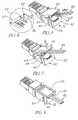
- FIG. 1is a perspective view of the present invention
- FIG. 2is an perspective exploded view of the present invention
- FIG. 3is a top view of the present invention
- FIG. 4is a cross-sectional view of the present invention taken along the section line A—A of FIG. 3;
- FIG. 5is a schematic view showing installation of the conductors on in the connector of the present invention.
- FIG. 6is a partial enlarged view showing installation of the conductors on in the connector of the present invention.
- FIG. 7is a schematic view showing insertion of the conductors into the connector of the present invention.
- FIG. 8is a schematic view showing complete operation of connector of the present invention.
- the electric connector of the present inventioncomprises a socket 10 having a connecting hole 11 at the rear top portion of socket 10 and a connecting bite 12 at bottom of socket 10 .
- the socket 10comprises a plurality of gutters at the front end of socket 10 , which gutters that receive a metal pin 16 therein, wherein the amount of metal pins can be set to 4, 6 or 8 metal pins, according to the connecting apparatus.
- the bottom of socket 10communicates with the gutters by a rabbet having a plurality of conductors 20 passing therethrough, wherein the two ends of the conductors 20 electrically couple to the metal pin 16 and a board 22 , respectively.
- the board 22includes a plurality of assembling holes 24 for assembling a plurality of golden pins 26 to thereby be respectively electrically coupled to the plurality of conductors 20 , each golden pin 26 having a forked shape.
- the number of golden pinscan be 2, 4, 6, or 8 pins, according to the application. Referring to FIG. 2, the number of metal pins 16 is 6 pins and the number of golden pins 26 is 4 pins, forming a 6P/4C type.
- the socket 10 and board 22are installed on a base 30 .
- the base 30includes a basement 32 which has two walls 34 on opposing sides thereof and rear wall 36 wherein the front of each wall 34 has a pivotal hole 38 and the rear of each wall 34 has a fastening hole 40 .
- the basement 32includes a plurality of ribs 44 for supporting the socket 10 and board 22 .
- the rear of basement 32has at least one screw column 46
- the front of basement 32has a placing gutter 48 disposed in correspondence to the connecting bite 12 of socket 10 for receiving the connecting bite 12 .
- the front of base 30places a chute 49 on opposing sides thereof.
- a cap 50is coupled to the base 30 by a screw 52 connecting the screw column 46 of base 30 for fastening the board 22 .
- the cap 50comprises a plurality of positioning holes 56 disposed in correspondence to the assembling holes 24 of board 22 for positioning the golden pins 26 .
- a sheet (stuffer cap) 60pivotally connects to the base 30 .
- the sheet 60has a pivotal column 62 formed on opposing sides thereof and in respective correspondence with the pivotal holes 38 of base 30 .
- the rear of sheet 60has a fastening column 64 formed on opposing sides thereof for respective fastening to the fastening holes 40 .
- the sheet 60includes a connecting opening 66 having a plurality of holes 68 for ordering the conductors.
- the top of socket 10includes a cap 70 which connects the rabbet 18 of socket 10 by an assembly 72 of cap 70 .
- the fastening column 64couples to the fastening holes 40 by pressing the sheet 60 down.
- the insulation of the conductors 80is peeled by the golden pins 26 , and the golden pins 26 make electrical contact with the conductors 80 .
- the electric connector of the present inventiondiscloses using the conductors 80 orderly inserted into the holes 68 and then pressing the sheet 60 , thereby solving the conventional assembly problems where a conductor is connected to the connector using a tool.
- the metal pins 16 of present inventioncan number 4, 6 and 8 correspond to the golden pins 26 that can number 2, 4, 6, and 8, according to the connecting apparatus. Additionally, for use in wire for telecommunications, the pins 16 can number 4 or 2 and correspond to the golden pins 26 that can number 4 or 2.
Landscapes
- Coupling Device And Connection With Printed Circuit (AREA)
- Connector Housings Or Holding Contact Members (AREA)
- Connections Arranged To Contact A Plurality Of Conductors (AREA)
- Details Of Connecting Devices For Male And Female Coupling (AREA)
Abstract
Description
1. Field of the Invention
The present invention relates to an electric connector, more particularity, to an electric connector having a structure for connecting the conductors without the use of hand tools.
2. Description of the Prior Art
There are many wired telecommunication and network apparatuses installed in homes or offices. Any of the transmission apparatuses needs the wire installed for transferring the data or electric signals, and two conductors need a connector to be coupled together. There are many kinds of connectors used in accordance with the number of conductors such as telecommunication devices have four to six electric junctions and network devices need six to eight electric junctions.
Before a conductor is coupled to the connector, the insulation must be peeled-off from the conductor by a hand tool. Therefore, the conductors of the wires can connect to the connector by using a hand tool. The disadvantages include an increase in the assembly cost by the use of a hand tool.
It is an object of the present invention is to provide an electric connector having a structure that does not require a hand tool for assembling a conductor to the connector.
It is another object of the present invention is to provide an electric connector which uses a plurality of holes for ordering the conductors inserted therein, so that it is convenient to assemble.
An electric connector of the present invention comprises a socket having a connecting bite at the bottom, and a plurality of gutters at the front communicating with a rabbet that passes a plurality of conductors therethrough. The front of each conductor electrically connects to a metal pin and the rear of the conductor electrically connects to a board. The board has a plurality of assembling holes for placing a plurality of golden pins therein. Further more, the socket and board install on a base.
The base has a basement which includes two walls at opposite sides of the basement, each wall having a pivotal hole at a front side and a fastening hole at each rear side. The base further includes a cap for fastening the board, which has a plurality of positioning holes disposed in correspondence to the assembling holes for positioning golden pins of the board, and a sheet that includes a pivotal column and a fastening column on each side thereof and disposed in respective correspondence to the positioning hole and fastening hole on each side of the base for pivoting the sheet on the base. There are a plurality of holes of the sheet for the convenience of assembling conductors into the connector.
The above and further objects, features and advantages of the invention will become clear from the following more detailed description when read with reference to the accompanying drawings in which:
FIG. 1 is a perspective view of the present invention;
FIG. 2 is an perspective exploded view of the present invention;
FIG. 3 is a top view of the present invention;
FIG. 4 is a cross-sectional view of the present invention taken along the section line A—A of FIG. 3;
FIG. 5 is a schematic view showing installation of the conductors on in the connector of the present invention;
FIG. 6 is a partial enlarged view showing installation of the conductors on in the connector of the present invention;
FIG. 7 is a schematic view showing insertion of the conductors into the connector of the present invention; and
FIG. 8 is a schematic view showing complete operation of connector of the present invention.
Refer to FIGS. 1,2,3, and4, the electric connector of the present invention comprises asocket 10 having a connectinghole 11 at the rear top portion ofsocket 10 and a connectingbite 12 at bottom ofsocket 10. And, thesocket 10 comprises a plurality of gutters at the front end ofsocket 10, which gutters that receive ametal pin 16 therein, wherein the amount of metal pins can be set to 4, 6 or 8 metal pins, according to the connecting apparatus. The bottom ofsocket 10 communicates with the gutters by a rabbet having a plurality ofconductors 20 passing therethrough, wherein the two ends of theconductors 20 electrically couple to themetal pin 16 and aboard 22, respectively. Theboard 22 includes a plurality of assemblingholes 24 for assembling a plurality ofgolden pins 26 to thereby be respectively electrically coupled to the plurality ofconductors 20, eachgolden pin 26 having a forked shape. The number of golden pins can be 2, 4, 6, or 8 pins, according to the application. Referring to FIG. 2, the number ofmetal pins 16 is 6 pins and the number ofgolden pins 26 is 4 pins, forming a 6P/4C type.
Thesocket 10 andboard 22 are installed on abase 30. Thebase 30 includes abasement 32 which has twowalls 34 on opposing sides thereof andrear wall 36 wherein the front of eachwall 34 has apivotal hole 38 and the rear of eachwall 34 has afastening hole 40. Thebasement 32 includes a plurality ofribs 44 for supporting thesocket 10 andboard 22. The rear ofbasement 32 has at least onescrew column 46, and the front ofbasement 32 has a placinggutter 48 disposed in correspondence to the connectingbite 12 ofsocket 10 for receiving the connectingbite 12. And, the front ofbase 30 places achute 49 on opposing sides thereof.
Acap 50 is coupled to thebase 30 by ascrew 52 connecting thescrew column 46 ofbase 30 for fastening theboard 22. Thecap 50 comprises a plurality ofpositioning holes 56 disposed in correspondence to the assemblingholes 24 ofboard 22 for positioning thegolden pins 26. Further, a sheet (stuffer cap)60 pivotally connects to thebase 30. Thesheet 60 has apivotal column 62 formed on opposing sides thereof and in respective correspondence with thepivotal holes 38 ofbase 30. The rear ofsheet 60 has afastening column 64 formed on opposing sides thereof for respective fastening to thefastening holes 40. Thesheet 60 includes a connecting opening66 having a plurality ofholes 68 for ordering the conductors. Further, the top ofsocket 10 includes acap 70 which connects therabbet 18 ofsocket 10 by anassembly 72 ofcap 70.
Referring to FIGS. 5,6,7, and8, when the plurality ofconductors 80 are orderly inserted into theholes 68, thefastening column 64 couples to the fasteningholes 40 by pressing thesheet 60 down. The insulation of theconductors 80 is peeled by thegolden pins 26, and thegolden pins 26 make electrical contact with theconductors 80.
The electric connector of the present invention discloses using theconductors 80 orderly inserted into theholes 68 and then pressing thesheet 60, thereby solving the conventional assembly problems where a conductor is connected to the connector using a tool. Themetal pins 16 of present invention can number 4, 6 and 8 correspond to thegolden pins 26 that can number 2, 4, 6, and 8, according to the connecting apparatus. Additionally, for use in wire for telecommunications, thepins 16 can number 4 or 2 and correspond to thegolden pins 26 that can number 4 or 2.
Therefore, the foregoing is considered as illustrative only of the principles of the invention. Further, since numerous modifications and changes will readily occur to those skilled in the art, it is not desired to limit the invention to the exact construction and operation shown and described, and accordingly, all suitable modifications and equivalents may be resorted to, falling within the scope of the invention.
Claims (7)
1. An electric connector for a plurality of wires, comprising:
a socket having a plurality of gutters, a plurality of metal pins respectively received in the plurality of gutters, and a connecting bite at a bottom of the socket, the socket having a rabbet which communicates with the gutters;
a board having a plurality of conductors coupled thereto and a plurality of assembling holes, wherein the conductors extend through the rabbet and are respectively electrically coupled to the plurality of metal pins;
a plurality of golden pins respectively mounted in the plurality of assembling holes of the board and respectively electrically coupled to the plurality of conductors, each of the plurality of golden pins having a contour for piercing insulation of a respective one of the plurality of wires and making electrical contact with of a conductor of the wire;
a base for receiving the socket and board having a basement formed between a pair of side walls, each of the side walls having a pivotal hole adjacent an upper front portion of the wall and a fastening hole adjacent an upper rear portion of the wall;
a first cap mounted on the base and having a plurality of positioning holes disposed in respective correspondence with the plurality of assembling holes for positioning the plurality of golden pins; and
a stuffer cap having a pivotal column respectively formed on opposing front side portions thereof and pivotally engaged with a corresponding pivotal hole of the base, a fastening column formed on opposing rear side portions thereof for respective engagement with a corresponding fastening hole of the base, and a plurality of holes formed in an inner surface of the stuffer cap for respectively receiving the plurality of wires therein.
2. The electric connector ofclaim 1 , wherein each of the golden pins is formed with a forked shape.
3. The electric connector ofclaim 1 , wherein the base has a plurality of ribs formed therein for supporting the socket and board.
4. The electric connector ofclaim 1 , wherein the socket has a connecting bite formed thereon disposed in correspondence to a placing gutter formed in the base.
5. The electric connector ofclaim 1 , wherein a second cap overlays a rear top portion of socket.
6. The electric connector ofclaim 5 , wherein the second cap has at least one assembly formed thereon for coupling with the rabbet of the socket.
7. The electric connector ofclaim 5 , wherein the second cap is coupled to an upper front portion of the side walls of the base.
Priority Applications (5)
| Application Number | Priority Date | Filing Date | Title |
|---|---|---|---|
| GB0303706AGB2398677A (en) | 2003-02-18 | 2003-02-18 | Electrical connector with IDC pins |
| US10/370,474US6682363B1 (en) | 2003-02-18 | 2003-02-24 | Insulation piercing connector |
| DE20303530UDE20303530U1 (en) | 2003-02-18 | 2003-03-05 | Electrical connector for automatic assembly |
| NL1022930ANL1022930C1 (en) | 2003-02-18 | 2003-03-14 | Electrical connector for automatic assembly to provide connection for a conductor or appropriate tools such as in telephone systems or computer networks |
| FR0303360AFR2852742B3 (en) | 2003-02-18 | 2003-03-19 | ELECTRICAL CONNECTOR FOR AUTOMATIC MOUNTING. |
Applications Claiming Priority (5)
| Application Number | Priority Date | Filing Date | Title |
|---|---|---|---|
| GB0303706AGB2398677A (en) | 2003-02-18 | 2003-02-18 | Electrical connector with IDC pins |
| US10/370,474US6682363B1 (en) | 2003-02-18 | 2003-02-24 | Insulation piercing connector |
| DE20303530UDE20303530U1 (en) | 2003-02-18 | 2003-03-05 | Electrical connector for automatic assembly |
| NL1022930ANL1022930C1 (en) | 2003-02-18 | 2003-03-14 | Electrical connector for automatic assembly to provide connection for a conductor or appropriate tools such as in telephone systems or computer networks |
| FR0303360AFR2852742B3 (en) | 2003-02-18 | 2003-03-19 | ELECTRICAL CONNECTOR FOR AUTOMATIC MOUNTING. |
Publications (1)
| Publication Number | Publication Date |
|---|---|
| US6682363B1true US6682363B1 (en) | 2004-01-27 |
Family
ID=33545573
Family Applications (1)
| Application Number | Title | Priority Date | Filing Date |
|---|---|---|---|
| US10/370,474Expired - Fee RelatedUS6682363B1 (en) | 2003-02-18 | 2003-02-24 | Insulation piercing connector |
Country Status (5)
| Country | Link |
|---|---|
| US (1) | US6682363B1 (en) |
| DE (1) | DE20303530U1 (en) |
| FR (1) | FR2852742B3 (en) |
| GB (1) | GB2398677A (en) |
| NL (1) | NL1022930C1 (en) |
Cited By (41)
| Publication number | Priority date | Publication date | Assignee | Title |
|---|---|---|---|---|
| US20030116935A1 (en)* | 2001-12-26 | 2003-06-26 | Adam Zadok | Anti-roll vehicle suspension |
| US20040022015A1 (en)* | 2002-07-31 | 2004-02-05 | Rung-Hua You | Signal plug structure |
| US20040110410A1 (en)* | 2002-09-28 | 2004-06-10 | Werner Boeck | Shielded connection arrangement for data transfer |
| BE1015495A3 (en)* | 2003-03-04 | 2005-05-03 | Hsu & Overmaat Co Ltd | Electrical connector for automatic assembly to provide connection for a conductor or appropriate tools such as in telephone systems or computer networks |
| US6932641B1 (en)* | 2004-02-20 | 2005-08-23 | Sheng Hsin Liao | Plug structure |
| US20050266721A1 (en)* | 2004-05-26 | 2005-12-01 | Milner John J | Electrical connector with strain relief |
| US7001204B1 (en)* | 2005-01-12 | 2006-02-21 | Jyh Eng Technology Co., Ltd. | Transmitting jack with prong-type conductive pieces |
| US7097493B1 (en)* | 2005-01-14 | 2006-08-29 | Adtran, Inc. | Apparatus and method for interfacing connectors to network components |
| US7112085B1 (en)* | 2003-11-19 | 2006-09-26 | Judco Manufacturing Inc. | Low profile insulation displacement connector |
| US20080115356A1 (en)* | 2006-11-17 | 2008-05-22 | Peterson Karl J | Cable preform tool |
| US20080200059A1 (en)* | 2007-02-19 | 2008-08-21 | Werner Boeck | Electrical Plug Module |
| US20080268719A1 (en)* | 2007-03-29 | 2008-10-30 | The Siemon Company | Modular Connector With Reduced Termination Variability And Improved Performance |
| US7498538B1 (en) | 2007-07-20 | 2009-03-03 | Judco Manufacturing, Inc. | Sliding contact switch |
| US7540760B1 (en)* | 2008-06-18 | 2009-06-02 | Surtec Industries, Inc. | Communication jack structure |
| US20100015844A1 (en)* | 2006-12-15 | 2010-01-21 | Longinos De Dios Martin | Connector for use in terminating communications cables |
| ES2345309A1 (en)* | 2006-07-11 | 2010-09-20 | Efapel- Empresa Fabril De Produtos Electricos, S.A. | RJ45 KEYSTONE AND TOOLLESS CONNECTOR AND ITS ASSEMBLY PROCESS. |
| US7880107B1 (en) | 2007-10-12 | 2011-02-01 | Judco Manufacturing, Inc. | Momentary push button switch |
| US7883354B1 (en)* | 2010-08-26 | 2011-02-08 | Hong Fu Jin Precision Industry (Shenzhen) Co., Ltd. | Modular plug |
| US8257117B2 (en) | 2011-01-20 | 2012-09-04 | Tyco Electronics Corporation | Electrical connector having a first group of terminals taller than that of a second group or located in a non-parallel plane |
| US8591248B2 (en) | 2011-01-20 | 2013-11-26 | Tyco Electronics Corporation | Electrical connector with terminal array |
| US8647146B2 (en) | 2011-01-20 | 2014-02-11 | Tyco Electronics Corporation | Electrical connector having crosstalk compensation insert |
| CN103618189A (en)* | 2013-11-13 | 2014-03-05 | 国家电网公司 | Installation tool for insulating piercing wire clamp |
| US8764476B1 (en) | 2012-12-06 | 2014-07-01 | Frank Ma | Transmission connector |
| US20140273658A1 (en)* | 2013-03-15 | 2014-09-18 | Ortronics, Inc. | Multi-Surface Contact Plug Assemblies, Systems and Methods |
| WO2015007939A3 (en)* | 2013-07-15 | 2015-03-19 | Te Connectivity Amp España, S.L.U. | Telecommunication plug for high data transmission |
| US9033725B2 (en) | 2012-04-19 | 2015-05-19 | Panduit Corp. | GG45 plug with hinging load bar |
| US9060661B2 (en) | 2012-11-09 | 2015-06-23 | Canplas Industries, Ltd. | Female electrical receptacle for mounting behind an inlet valve of a central vacuum cleaning system |
| CN105324886A (en)* | 2013-05-21 | 2016-02-10 | 泰连德国有限公司 | Electrical connector |
| US9379500B2 (en) | 2013-03-11 | 2016-06-28 | Panduit Corp. | Front sled assemblies for communication jacks and communication jacks having front sled assemblies |
| CN105765790A (en)* | 2013-11-25 | 2016-07-13 | 泰连德国有限公司 | Arrangement for an electrical connector |
| US20170140884A1 (en)* | 2015-11-16 | 2017-05-18 | Rich Brand Industries Limited | In-Line Slide Switch |
| CN107810580A (en)* | 2015-06-29 | 2018-03-16 | 威德米勒界面有限公司及两合公司 | Plug-in connector |
| US20180277977A1 (en)* | 2017-03-24 | 2018-09-27 | Alpine Electronics, Inc. | Structure of electrical connector casing and method of using same |
| US10148048B2 (en) | 2016-05-20 | 2018-12-04 | Communications Systems, Inc. | Toolless communications jack |
| EP3425746A4 (en)* | 2016-03-09 | 2019-02-20 | Ningbo Betterbell Telecommunication Equipment Co., Ltd. | INTELLIGENT INFORMATION SHEET PRACTICAL WITHOUT INDIVIDUALIZED DIVIDED TYPE TOOL |
| JP2021018877A (en)* | 2019-07-18 | 2021-02-15 | 日本航空電子工業株式会社 | Connector and cable harness |
| US11239606B2 (en)* | 2020-03-18 | 2022-02-01 | Lear Corporation | Electrical connector assembly |
| US20230057001A1 (en)* | 2021-08-19 | 2023-02-23 | Panduit Corp. | Field terminable ethernet connector with integral termination cap |
| US11710910B2 (en) | 2018-09-05 | 2023-07-25 | Panduit Corp. | Field terminable single pair ethernet connector |
| US11742606B2 (en) | 2021-06-18 | 2023-08-29 | Lear Corporation | Electrical terminal and electrical connector assembly for electrically conductive structures |
| US11855377B2 (en) | 2021-07-20 | 2023-12-26 | Lear Corporation | Spring pin terminals for an electrical connector assembly that provides mechanical and electrical connections between two electrically conductive structures |
Families Citing this family (5)
| Publication number | Priority date | Publication date | Assignee | Title |
|---|---|---|---|---|
| DE202004006139U1 (en)* | 2004-04-15 | 2005-09-01 | Weidmüller Interface GmbH & Co. KG | Connector for a cable |
| DE202004013335U1 (en)* | 2004-04-15 | 2005-09-01 | Weidmüller Interface GmbH & Co. KG | Connecting device for connecting the conductors of a ribbon cable |
| DE202006018019U1 (en)* | 2006-11-02 | 2008-03-13 | Weidmüller Interface GmbH & Co. KG | Plug connection, in particular for sensor / actuator cables |
| GB2475490A (en)* | 2009-11-18 | 2011-05-25 | Gfi Cables Ltd | Electrical connector with pivoting wire fixture |
| DE102015219166A1 (en)* | 2015-10-05 | 2017-04-06 | Robert Bosch Gmbh | Polarity reversal protection of a plug to increase safety when using electrical connectors |
Citations (3)
| Publication number | Priority date | Publication date | Assignee | Title |
|---|---|---|---|---|
| US5762518A (en)* | 1995-03-31 | 1998-06-09 | Matsushita Electric Works, Ltd. | Lever modular jack telephone type connector |
| US5947761A (en)* | 1998-09-29 | 1999-09-07 | The Whitaker Corporation | Electrical connector with pivoting wire fixture |
| US6116943A (en)* | 1998-06-30 | 2000-09-12 | The Whitaker Corporation | Modular plug having a circuit board |
Family Cites Families (5)
| Publication number | Priority date | Publication date | Assignee | Title |
|---|---|---|---|---|
| JPH08273707A (en)* | 1995-03-31 | 1996-10-18 | Matsushita Electric Works Ltd | Modular connector |
| US5667402A (en)* | 1995-12-15 | 1997-09-16 | Denovich; Sam | Wire carrier for electrical connector modular |
| JP2000048893A (en)* | 1998-07-28 | 2000-02-18 | Matsushita Electric Works Ltd | Modular jack |
| US6157542A (en)* | 1999-06-23 | 2000-12-05 | Hsing Chau Industrial Co., Ltd. | Electric jack |
| DE60124727T2 (en)* | 2000-08-17 | 2007-09-13 | Tyco Electronics Amp Gmbh | ELECTRICAL CONNECTOR FOR DATA TRANSMISSION IN AN OPERATING ENVIRONMENT |
- 2003
- 2003-02-18GBGB0303706Apatent/GB2398677A/ennot_activeWithdrawn
- 2003-02-24USUS10/370,474patent/US6682363B1/ennot_activeExpired - Fee Related
- 2003-03-05DEDE20303530Upatent/DE20303530U1/ennot_activeExpired - Lifetime
- 2003-03-14NLNL1022930Apatent/NL1022930C1/ennot_activeIP Right Cessation
- 2003-03-19FRFR0303360Apatent/FR2852742B3/ennot_activeExpired - Lifetime
Patent Citations (3)
| Publication number | Priority date | Publication date | Assignee | Title |
|---|---|---|---|---|
| US5762518A (en)* | 1995-03-31 | 1998-06-09 | Matsushita Electric Works, Ltd. | Lever modular jack telephone type connector |
| US6116943A (en)* | 1998-06-30 | 2000-09-12 | The Whitaker Corporation | Modular plug having a circuit board |
| US5947761A (en)* | 1998-09-29 | 1999-09-07 | The Whitaker Corporation | Electrical connector with pivoting wire fixture |
Cited By (70)
| Publication number | Priority date | Publication date | Assignee | Title |
|---|---|---|---|---|
| US20030116935A1 (en)* | 2001-12-26 | 2003-06-26 | Adam Zadok | Anti-roll vehicle suspension |
| US20040022015A1 (en)* | 2002-07-31 | 2004-02-05 | Rung-Hua You | Signal plug structure |
| US20040110410A1 (en)* | 2002-09-28 | 2004-06-10 | Werner Boeck | Shielded connection arrangement for data transfer |
| US6887094B2 (en)* | 2002-09-28 | 2005-05-03 | Tyco Electronics Amp, Gmbh | Shielded connection arrangement for data transfer |
| BE1015495A3 (en)* | 2003-03-04 | 2005-05-03 | Hsu & Overmaat Co Ltd | Electrical connector for automatic assembly to provide connection for a conductor or appropriate tools such as in telephone systems or computer networks |
| US7175467B2 (en) | 2003-11-19 | 2007-02-13 | Judco Manufacturing, Inc. | Low profile insulation displacement connector |
| US7112085B1 (en)* | 2003-11-19 | 2006-09-26 | Judco Manufacturing Inc. | Low profile insulation displacement connector |
| US20060258202A1 (en)* | 2003-11-19 | 2006-11-16 | Judco Manufacturing Inc. | Low profile insulation displacement connector |
| US20050186835A1 (en)* | 2004-02-20 | 2005-08-25 | Liao Sheng H. | Plug structure |
| US6932641B1 (en)* | 2004-02-20 | 2005-08-23 | Sheng Hsin Liao | Plug structure |
| US20050266721A1 (en)* | 2004-05-26 | 2005-12-01 | Milner John J | Electrical connector with strain relief |
| US7001204B1 (en)* | 2005-01-12 | 2006-02-21 | Jyh Eng Technology Co., Ltd. | Transmitting jack with prong-type conductive pieces |
| US7097493B1 (en)* | 2005-01-14 | 2006-08-29 | Adtran, Inc. | Apparatus and method for interfacing connectors to network components |
| ES2345309B1 (en)* | 2006-07-11 | 2011-09-05 | Efapel- Empresa Fabril De Produtos Electricos, S.A. | RJ45 KEYSTONE AND TOOLLESS CONNECTOR AND ITS ASSEMBLY PROCESS. |
| ES2345309A1 (en)* | 2006-07-11 | 2010-09-20 | Efapel- Empresa Fabril De Produtos Electricos, S.A. | RJ45 KEYSTONE AND TOOLLESS CONNECTOR AND ITS ASSEMBLY PROCESS. |
| US20080115356A1 (en)* | 2006-11-17 | 2008-05-22 | Peterson Karl J | Cable preform tool |
| US20100015844A1 (en)* | 2006-12-15 | 2010-01-21 | Longinos De Dios Martin | Connector for use in terminating communications cables |
| US8070506B2 (en)* | 2006-12-15 | 2011-12-06 | Tyco Electronics Amp Espana Sa | Connector for use in terminating communications cables |
| US7559790B2 (en)* | 2007-02-19 | 2009-07-14 | Tyco Electronics Amp Gmbh | Electrical plug module |
| US20080200059A1 (en)* | 2007-02-19 | 2008-08-21 | Werner Boeck | Electrical Plug Module |
| US8267714B2 (en)* | 2007-03-29 | 2012-09-18 | The Siemon Company | Modular connector with reduced termination variability and improved performance |
| US20080268719A1 (en)* | 2007-03-29 | 2008-10-30 | The Siemon Company | Modular Connector With Reduced Termination Variability And Improved Performance |
| US7498538B1 (en) | 2007-07-20 | 2009-03-03 | Judco Manufacturing, Inc. | Sliding contact switch |
| US7880107B1 (en) | 2007-10-12 | 2011-02-01 | Judco Manufacturing, Inc. | Momentary push button switch |
| US7540760B1 (en)* | 2008-06-18 | 2009-06-02 | Surtec Industries, Inc. | Communication jack structure |
| US7883354B1 (en)* | 2010-08-26 | 2011-02-08 | Hong Fu Jin Precision Industry (Shenzhen) Co., Ltd. | Modular plug |
| US8591248B2 (en) | 2011-01-20 | 2013-11-26 | Tyco Electronics Corporation | Electrical connector with terminal array |
| US9203192B2 (en) | 2011-01-20 | 2015-12-01 | Tyco Electronics Services Gmbh | Electrical connector having crosstalk compensation insert |
| US8647146B2 (en) | 2011-01-20 | 2014-02-11 | Tyco Electronics Corporation | Electrical connector having crosstalk compensation insert |
| US10135193B2 (en) | 2011-01-20 | 2018-11-20 | Commscope Technologies Llc | Electrical connector having crosstalk compensation insert |
| US9722359B2 (en) | 2011-01-20 | 2017-08-01 | Commscope Technologies Llc | Electrical connector with terminal array |
| US9698534B2 (en) | 2011-01-20 | 2017-07-04 | Commscope Technologies Llc | Electrical connector having crosstalk compensation insert |
| US9461409B2 (en) | 2011-01-20 | 2016-10-04 | Commscope Technologies Llc | Electrical connector with terminal array |
| US8257117B2 (en) | 2011-01-20 | 2012-09-04 | Tyco Electronics Corporation | Electrical connector having a first group of terminals taller than that of a second group or located in a non-parallel plane |
| US9601885B2 (en) | 2012-04-19 | 2017-03-21 | Panduit Corp. | GG45 plug with hinging load bar |
| US9033725B2 (en) | 2012-04-19 | 2015-05-19 | Panduit Corp. | GG45 plug with hinging load bar |
| US9060661B2 (en) | 2012-11-09 | 2015-06-23 | Canplas Industries, Ltd. | Female electrical receptacle for mounting behind an inlet valve of a central vacuum cleaning system |
| US8764476B1 (en) | 2012-12-06 | 2014-07-01 | Frank Ma | Transmission connector |
| US9800005B2 (en) | 2013-03-11 | 2017-10-24 | Panduit Corp. | Front sled assemblies for communication jacks and communication jacks having front sled assemblies |
| US9379500B2 (en) | 2013-03-11 | 2016-06-28 | Panduit Corp. | Front sled assemblies for communication jacks and communication jacks having front sled assemblies |
| US8992247B2 (en)* | 2013-03-15 | 2015-03-31 | Ortronics, Inc. | Multi-surface contact plug assemblies, systems and methods |
| US20140273658A1 (en)* | 2013-03-15 | 2014-09-18 | Ortronics, Inc. | Multi-Surface Contact Plug Assemblies, Systems and Methods |
| CN105324886B (en)* | 2013-05-21 | 2018-12-25 | 泰连德国有限公司 | electrical connector |
| JP2016522549A (en)* | 2013-05-21 | 2016-07-28 | ティーイー コネクティビティ ジャーマニー ゲゼルシャフト ミット ベシュレンクテル ハフツンクTE Connectivity Germany GmbH | Electrical connector |
| US9960549B2 (en) | 2013-05-21 | 2018-05-01 | Te Connectivity Germany Gmbh | Electrical connector |
| CN105324886A (en)* | 2013-05-21 | 2016-02-10 | 泰连德国有限公司 | Electrical connector |
| WO2015007939A3 (en)* | 2013-07-15 | 2015-03-19 | Te Connectivity Amp España, S.L.U. | Telecommunication plug for high data transmission |
| US10056703B2 (en) | 2013-07-15 | 2018-08-21 | CommScope Connectivity Spain, S.L. | Telecommunications plug for high data rate applications |
| CN103618189A (en)* | 2013-11-13 | 2014-03-05 | 国家电网公司 | Installation tool for insulating piercing wire clamp |
| CN103618189B (en)* | 2013-11-13 | 2016-03-02 | 国家电网公司 | A kind of insulation puncture line clamping erecting tools |
| US10033118B2 (en) | 2013-11-25 | 2018-07-24 | Te Connectivity Germany Gmbh | Arrangement for an electrical connector |
| CN105765790B (en)* | 2013-11-25 | 2019-11-26 | 泰连德国有限公司 | Devices for electrical connectors |
| CN105765790A (en)* | 2013-11-25 | 2016-07-13 | 泰连德国有限公司 | Arrangement for an electrical connector |
| US20180183174A1 (en)* | 2015-06-29 | 2018-06-28 | Weidmüller Interface GmbH & Co. KG | Plug-in connector |
| CN107810580A (en)* | 2015-06-29 | 2018-03-16 | 威德米勒界面有限公司及两合公司 | Plug-in connector |
| EP3314700A1 (en)* | 2015-06-29 | 2018-05-02 | Weidmüller Interface GmbH & Co. KG | Plug-in connector |
| US9767972B2 (en)* | 2015-11-16 | 2017-09-19 | Rich Brand Industries Limited | In-line slide switch |
| US20170140884A1 (en)* | 2015-11-16 | 2017-05-18 | Rich Brand Industries Limited | In-Line Slide Switch |
| EP3425746A4 (en)* | 2016-03-09 | 2019-02-20 | Ningbo Betterbell Telecommunication Equipment Co., Ltd. | INTELLIGENT INFORMATION SHEET PRACTICAL WITHOUT INDIVIDUALIZED DIVIDED TYPE TOOL |
| US10148048B2 (en) | 2016-05-20 | 2018-12-04 | Communications Systems, Inc. | Toolless communications jack |
| US20180277977A1 (en)* | 2017-03-24 | 2018-09-27 | Alpine Electronics, Inc. | Structure of electrical connector casing and method of using same |
| US10530103B2 (en)* | 2017-03-24 | 2020-01-07 | Alpine Electronics, Inc. | Structure of electrical connector casing |
| US11710910B2 (en) | 2018-09-05 | 2023-07-25 | Panduit Corp. | Field terminable single pair ethernet connector |
| JP2021018877A (en)* | 2019-07-18 | 2021-02-15 | 日本航空電子工業株式会社 | Connector and cable harness |
| JP7249226B2 (en) | 2019-07-18 | 2023-03-30 | 日本航空電子工業株式会社 | Connectors and cable harnesses |
| US11239606B2 (en)* | 2020-03-18 | 2022-02-01 | Lear Corporation | Electrical connector assembly |
| US11742606B2 (en) | 2021-06-18 | 2023-08-29 | Lear Corporation | Electrical terminal and electrical connector assembly for electrically conductive structures |
| US11855377B2 (en) | 2021-07-20 | 2023-12-26 | Lear Corporation | Spring pin terminals for an electrical connector assembly that provides mechanical and electrical connections between two electrically conductive structures |
| US20230057001A1 (en)* | 2021-08-19 | 2023-02-23 | Panduit Corp. | Field terminable ethernet connector with integral termination cap |
| US11705681B2 (en)* | 2021-08-19 | 2023-07-18 | Panduit Corp. | Field terminable ethernet connector with integral termination cap |
Also Published As
| Publication number | Publication date |
|---|---|
| FR2852742B3 (en) | 2005-02-11 |
| NL1022930C1 (en) | 2004-09-20 |
| DE20303530U1 (en) | 2003-05-08 |
| FR2852742A3 (en) | 2004-09-24 |
| GB0303706D0 (en) | 2003-03-19 |
| GB2398677A (en) | 2004-08-25 |
Similar Documents
| Publication | Publication Date | Title |
|---|---|---|
| US6682363B1 (en) | Insulation piercing connector | |
| US6464542B1 (en) | Connector assembly having small profile | |
| EP0519196B1 (en) | A terminal block for printed circuit boards | |
| US4225205A (en) | Electrical connector for terminating a flat conductor cable | |
| US4863393A (en) | Modular jack assembly with improved bridging arrangement | |
| US6065976A (en) | Coaxial cable connector | |
| US5618202A (en) | Connector having strip line structure | |
| JPH0357018Y2 (en) | ||
| US6213815B1 (en) | Multimedia electric adapter | |
| US6280229B1 (en) | Plug connector | |
| US6428343B1 (en) | Electrical connector for power conductors | |
| US5190481A (en) | Structure of the switching device for electrical connector | |
| US5562463A (en) | I/O card with flexible extending I/O port | |
| US5947752A (en) | Video data transmission connector and transmission cable mounting arrangement | |
| US6142821A (en) | Electrical connector assembly with guiding device | |
| US5893763A (en) | Transition adapter for conductor cables | |
| EP1166400B1 (en) | Electrical connector | |
| EP0295693B1 (en) | Multiple junction device | |
| US6019641A (en) | Electric connector | |
| US6994561B2 (en) | Cross connect interface module | |
| US20040127088A1 (en) | Wiring block and cover shell arrangement for electric connector | |
| US7156687B1 (en) | Insulation displacement connection connector assembly with cable positioning recesses | |
| US6364715B1 (en) | Composite interface structure for jack-plug sockets | |
| JPS6332224B2 (en) | ||
| US6312292B2 (en) | Low crosstalk connector |
Legal Events
| Date | Code | Title | Description |
|---|---|---|---|
| AS | Assignment | Owner name:HSU & OVERMATT CO., LTD., TAIWAN Free format text:ASSIGNMENT OF ASSIGNORS INTEREST;ASSIGNOR:CHANG, YUNG TUNG;REEL/FRAME:013805/0127 Effective date:20030127 | |
| FEPP | Fee payment procedure | Free format text:PAYOR NUMBER ASSIGNED (ORIGINAL EVENT CODE: ASPN); ENTITY STATUS OF PATENT OWNER: SMALL ENTITY | |
| FPAY | Fee payment | Year of fee payment:4 | |
| REMI | Maintenance fee reminder mailed | ||
| LAPS | Lapse for failure to pay maintenance fees | ||
| STCH | Information on status: patent discontinuation | Free format text:PATENT EXPIRED DUE TO NONPAYMENT OF MAINTENANCE FEES UNDER 37 CFR 1.362 | |
| FP | Lapsed due to failure to pay maintenance fee | Effective date:20120127 |