US6682228B2 - Connector housing for fiber-optic module - Google Patents
Connector housing for fiber-optic moduleDownload PDFInfo
- Publication number
- US6682228B2 US6682228B2US10/080,171US8017102AUS6682228B2US 6682228 B2US6682228 B2US 6682228B2US 8017102 AUS8017102 AUS 8017102AUS 6682228 B2US6682228 B2US 6682228B2
- Authority
- US
- United States
- Prior art keywords
- coupled
- side wall
- connector housing
- sleeve
- ferrule
- Prior art date
- Legal status (The legal status is an assumption and is not a legal conclusion. Google has not performed a legal analysis and makes no representation as to the accuracy of the status listed.)
- Expired - Lifetime
Links
Images


Classifications
- G—PHYSICS
- G02—OPTICS
- G02B—OPTICAL ELEMENTS, SYSTEMS OR APPARATUS
- G02B6/00—Light guides; Structural details of arrangements comprising light guides and other optical elements, e.g. couplings
- G02B6/24—Coupling light guides
- G02B6/36—Mechanical coupling means
- G02B6/38—Mechanical coupling means having fibre to fibre mating means
- G02B6/3807—Dismountable connectors, i.e. comprising plugs
- G02B6/3869—Mounting ferrules to connector body, i.e. plugs
- G—PHYSICS
- G02—OPTICS
- G02B—OPTICAL ELEMENTS, SYSTEMS OR APPARATUS
- G02B6/00—Light guides; Structural details of arrangements comprising light guides and other optical elements, e.g. couplings
- G02B6/24—Coupling light guides
- G02B6/36—Mechanical coupling means
- G02B6/38—Mechanical coupling means having fibre to fibre mating means
- G02B6/3807—Dismountable connectors, i.e. comprising plugs
- G02B6/381—Dismountable connectors, i.e. comprising plugs of the ferrule type, e.g. fibre ends embedded in ferrules, connecting a pair of fibres
- G02B6/3825—Dismountable connectors, i.e. comprising plugs of the ferrule type, e.g. fibre ends embedded in ferrules, connecting a pair of fibres with an intermediate part, e.g. adapter, receptacle, linking two plugs
- G—PHYSICS
- G02—OPTICS
- G02B—OPTICAL ELEMENTS, SYSTEMS OR APPARATUS
- G02B6/00—Light guides; Structural details of arrangements comprising light guides and other optical elements, e.g. couplings
- G02B6/24—Coupling light guides
- G02B6/36—Mechanical coupling means
- G02B6/38—Mechanical coupling means having fibre to fibre mating means
- G02B6/3807—Dismountable connectors, i.e. comprising plugs
- G02B6/389—Dismountable connectors, i.e. comprising plugs characterised by the method of fastening connecting plugs and sockets, e.g. screw- or nut-lock, snap-in, bayonet type
- G—PHYSICS
- G02—OPTICS
- G02B—OPTICAL ELEMENTS, SYSTEMS OR APPARATUS
- G02B6/00—Light guides; Structural details of arrangements comprising light guides and other optical elements, e.g. couplings
- G02B6/24—Coupling light guides
- G02B6/36—Mechanical coupling means
- G02B6/38—Mechanical coupling means having fibre to fibre mating means
- G02B6/3807—Dismountable connectors, i.e. comprising plugs
- G02B6/3897—Connectors fixed to housings, casing, frames or circuit boards
- G—PHYSICS
- G02—OPTICS
- G02B—OPTICAL ELEMENTS, SYSTEMS OR APPARATUS
- G02B6/00—Light guides; Structural details of arrangements comprising light guides and other optical elements, e.g. couplings
- G02B6/24—Coupling light guides
- G02B6/36—Mechanical coupling means
- G02B6/38—Mechanical coupling means having fibre to fibre mating means
- G02B6/3807—Dismountable connectors, i.e. comprising plugs
- G02B6/381—Dismountable connectors, i.e. comprising plugs of the ferrule type, e.g. fibre ends embedded in ferrules, connecting a pair of fibres
- G02B6/3818—Dismountable connectors, i.e. comprising plugs of the ferrule type, e.g. fibre ends embedded in ferrules, connecting a pair of fibres of a low-reflection-loss type
- G02B6/3821—Dismountable connectors, i.e. comprising plugs of the ferrule type, e.g. fibre ends embedded in ferrules, connecting a pair of fibres of a low-reflection-loss type with axial spring biasing or loading means
Definitions
- the present inventionrelates to fiber optic connectors, and more particularly to fiber optic connectors for fiber-optic transmitters, receivers, and transceivers, collectively referred to as fiber-optic modules.
- Fiber-optic modules for communication applicationsare well known in the art.
- a plurality of such fiber-optic modulesis provided on a printed circuit board (PCB) of a network card.
- Connectorized optical fibersare used to optically couple these modules to each other and to other optical devices in a system.
- Some of the optical devicesinclude passive components, such as, fiber cable adapters.
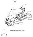
- FIG. 1Aillustrates a conventional connector mounted at an end of a single or multiple optical fibers. Strains of multiple optical fibers are referred to as fiber ribbons.
- the connector 100comprises a ferrule 108 and a connector housing.
- the connector housingcomprises a boot assembly 102 and a coupling 104 . Residing within the connector housing are optical fibers contained within a fiber ribbon 106 , with the bare fiber ends held in the ferrule 108 .
- FIG. 1Billustrates in more detail the conventional connector.
- the boot assembly 102 of the connector 100comprises a boot 1 , a crimp ring 2 , a spring push 3 , a spring 4 , a pin clamp 5 , and a guide pin 6 .
- the coupling 104comprises slots 7 along its sides.
- the pieces 1-6 of the boot assembly 102 and the coupling 104are slipped onto the fiber ribbon 106 .
- the ferrule 108 and the bare fibers within the ferrule 108are fabricated.
- the ferrule 108 and fiber endsare polished simultaneously.
- the boot assembly 102 and coupling 104are assembled so that the ferrule 108 and a portion of the fiber ribbon 106 reside within the boot assembly 102 and coupling 104 .
- the assembled connector 100can then be plugged into a connector receptacle of a transceiver.
- the spring 4facilitates a good optical interface between the ferrule 108 in the connector 100 and the connector receptacle in the fiber-optic module.
- the connector 100is conventionally known as a MPO connector according to the standard IEC 61754-7, which has an MT ferrule according to the standard IEC 61754-5. Other types of optical connectors also exist in industry.
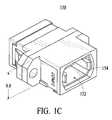
- FIG. 1Cillustrates a conventional connector receptacle.
- the receptaclemay be a part of a fiber-optic module (not shown).or an adapter to mate the conventional connector to another connector.
- the receptacle 150comprises an opening 152 .
- the opening 152comprises a plurality of fingers 154 .
- the receptacle 150has two fingers 154 .
- the fingers 154are capable of flexing outward when force is applied to move them such. When the force is removed, the fingers 154 return to their original positions.
- the connector 100is inserted into the opening 152 of the receptacle 150 , the fingers 154 slide within the slots 7 and engage the coupling 104 .
- the fiber-optic modulesare typically arranged in an array or multiple staggered arrays, which are positioned between other components. When greater bandwidth is desired, additional PCB's with transceivers can be installed. Alternatively, the number of fiber-optic modules per circuit board can be increased by reducing the area requirement for each module and its associated connector. The latter provides desirable space and cost savings.
- the conventional connector 100is 46.4 mm in length, 12.55 mm in width, and 7.6 mm in height. This size adds to the area of the fiber-optic module and connector used on the PCB and limits the number of modules that can be placed on the PCB, both in width and length. The space and cost savings and bandwidth per board are thus also limited.
- the improved optical connectorshould be cost effective to manufacture.
- the present inventionaddresses such a need.
- a connector housing for a connector to an optical deviceincludes: a body with a bottom wall, a first side wall with a first lip, a second side wall with a second lip, where optical fibers may reside within the bottom, first side, and second side walls, where the first and second lips engage the optical fibers when residing within the bottom, first, and second side walls, where the first and second lips assist in preventing the optical fibers from being removed from the body; a spring coupled to the body and the optical fibers; and a sleeve coupled to the body, including a locking feature for locking the body to the optical device.
- the connector housingis compact in size, allowing larger numbers of transceivers to reside on a printed circuit board, increasing its density for optical devices.
- a connector with the connector housingis also more cost effective to manufacture.
- FIG. 1Aillustrates a conventional connector mounted at an end of a single or multiple optical fibers.
- FIG. 1Billustrates in more detail the conventional connector.
- FIG. 1Cillustrates a conventional connector receptacle.
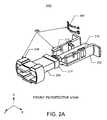
- FIGS. 2A and 2Billustrate a front perspective view and back perspective view, respectively, of a preferred embodiment of a connector in accordance with the present invention.
- FIGS. 3A-3Dillustrate perspective, top, end, and side views, respectively, of the connector body of the preferred embodiment of the connector in accordance with the present invention.
- FIGS. 4A-4Dillustrate perspective, side, top, and end views, respectively, of the connector sleeve of the preferred embodiment of the connector in accordance with the present invention.
- FIGS. 4E-4Fillustrate a first and a second cross sectional view, respectively, of the connector sleeve of the preferred embodiment of the connector in accordance with the present invention.
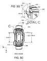
- FIGS. 5A-5Cillustrate top, side, and end views, respectively, of details of the preferred embodiment of the connector in accordance with the present invention.
- FIG. 5Dillustrates a detailed end view of the ferrule as it resides with the body of the connector in accordance with the present invention.
- FIG. 6Aillustrates a cross-sectional view of the ferrule as it resides with the body of the connector in accordance with the present invention.
- FIG. 6Billustrates a cross sectional view of the connector sleeve engaging the ridges in the connection in accordance with the present invention.
- FIG. 6Cillustrates an enlarged view of area D of FIG. 6 B.
- the present inventionprovides an improved optical connector that allows increased density for optical devices on circuit boards.
- the following descriptionis presented to enable one of ordinary skill in the art to make and use the invention and is provided in the context of a patent application and its requirements. Various modifications to the preferred embodiment will be readily apparent to those skilled in the art and the generic principles herein may be applied to other embodiments. Thus, the present invention is not intended to be limited to the embodiment shown but is to be accorded the widest scope consistent with the principles and features described herein.
- the connector in accordance with the present inventioncomprises a connector housing coupled to a ferrule and fiber ribbon.
- the connector housingcomprises features that allow the connector to couple to a receptacle comprising a fiber-optic module or another optical device.
- the connector housingis compact in size, allowing larger numbers of fiber-optic modules to reside on a printed circuit board, increasing its density for modules and other optical devices.
- the connector in accordance with the present inventionis also more cost effective to manufacture.
- FIGS. 2A through 6Cin conjunction with the discussion below.
- FIGS. 2A and 2Billustrate a front perspective view and back perspective view, respectively, of a preferred embodiment of a connector in accordance with the present invention.
- the connector 200comprises a connector housing 250 , a ferrule 208 , and a fiber ribbon 210 .
- the connector housing 250comprises a body 202 , a sleeve 204 , and a spring 206 .
- the ferrule 208can be a conventional ferrule, such as the MT ferrule.
- the connector housing 250thus can perform the same function as the connector housing of the MPO connector illustrated in FIGS. 1A and 1B.
- the ferrule 208comprises a flange 214 , which is the largest part of the ferrule 208 .
- the ferrule 208 and a portion of the fiber ribbon 210reside within the body 202 .
- the spring 206engages the ferrule 208 so that when the connector 200 is plugged into a receptacle of a transceiver, a good optical interface is provided between the ferrule 208 and the transceiver.
- the sleeve 204slides onto the body 202 and comprises features that engage the receptacle 150 .
- one or more coil springs 212can be used instead.
- the body 202 and the sleeve 204are composed of molded plastic, and the spring 206 or 212 is composed of sheet metal.
- the spring 206 or 212is illustrated as a part separate from the body 202 of the connector housing 250 , its features may be molded as part of the body 202 without departing from the spirit and scope of the present invention.
- FIGS. 3A-3Dillustrate perspective, top, end, and side views, respectively, of the connector body of the preferred embodiment of the connector in accordance with the present invention.
- the body 202comprises a bottom wall 302 and two side walls 304 and 306 coupled to one face of the bottom wall 302 . Coupled to one end of the side walls 304 and 306 are tabs 308 , which facilitate easy insertion and removal with the fingers.
- Each of the side walls 304 and 306comprise a pair of ridges 312 , a notch 314 , a slot 316 , and an indention 318 , as illustrated.
- the body 202also comprises protrusions 310 coupled to each side wall 304 and 306 and the bottom wall 302 , where the protrusions 310 extend toward each other. At an end of the side walls 304 and 306 opposite to the tabs 308 , the side walls 304 and 306 each comprise lips 320 and slanted faces 324 . Also coupled to the bottom wall 302 at a face opposite to the side walls 304 and 306 , is a slab 322 . The functions of the protrusions 310 , ridges 312 , notches 314 , slots 316 , indentions 318 , lips 320 , slab 322 , and slanted faces 324 will be described below with FIGS. 5A-5C.
- the body 202also comprises an area 326 for holding the flange 214 of the ferrule 208 .
- the length of the bottom wall 302 along the z-axisis 14.45 mm.
- the width of the bottom wall 302 along the x-axisis 9.12 mm.
- the distance between the side walls 304 and 306is 6.61 mm.
- the distance between the two protrusions 310is 3.16 mm.
- the length of the area 326is 3.22 mm.
- the heights of the side walls 304 and 306 along the y-axisare 4.25 mm.
- the height of the body 202 along the y-axis, including the slab 322is 4.82 mm.
- a connector body with other dimensionsis possible without departing from the spirit and scope of the present invention.
- FIGS. 4A-4Dillustrate perspective, side, top, and end views, respectively, of the connector sleeve of the preferred embodiment of the connector in accordance with the present invention.
- the sleeve 204comprises a top wall 402 , a bottom wall 404 , and two side walls 406 and 408 coupled to the top 402 and bottom 404 walls.
- the sleeve 204comprises a tab 410 coupled to the top wall 402 that protrudes away from the sleeve 204 .
- the sleeve 204also comprises an indention 412 in the bottom wall 404 . The functions of the tab 410 and indention 412 will be described below with FIGS. 5A-5C.
- FIGS. 4E-4Fillustrate a first and a second cross sectional view, respectively, of the connector sleeve of the preferred embodiment of the connector in accordance with the present invention.
- the first cross sectional view in FIG. 4Ecorresponds to the G—G cross section of the sleeve 204 , as labeled in FIG. 4 C.
- the second cross sectional view in FIG. 4Fcorresponds to the F—F cross-section of the sleeve 204 , as labeled in FIG. 4 D.
- the sleeve 204comprises tabs 414 which protrude inward. The functions of the tabs 414 will be described below with FIG. 6 B.
- the inner radius of the sleeve 204 in the x-y planeis 4.85 mm
- the outer radius of the sleeve 204 along the x-y planeis 6.10 mm
- the height of the sleeve 204 along the y-axisis 7.17 mm.
- a connector sleeve 204 with other dimensionsis A possible without departing from the spirit and scope of the present invention.
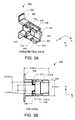
- FIGS. 5A-5Cillustrate top, side, and end views, respectively, of details of the preferred embodiment of the connector in accordance with the present invention.
- a polished ferrule 208 with the fiber ribbon 210is first fabricated.
- the spring 206is then inserted onto the back side of the flange 214 of the ferrule 208 .
- the spring 206comprises a slit. The spring 206 is inserted such that the ferrule 208 resides within the slit.
- the spring 206 and ferrule 208 with the fiber ribbon 210are then placed within the body 202 , such that the ferrule 208 abuts the bottom wall 302 , the side walls 304 and 306 , and the protrusions 310 .
- the flange 214 of the ferrule 208resides within the area 326 of the body 202 .
- the spring 206resides within the notches 314 (see FIG. 3A) in the side walls 304 and 306 .
- the notches 314assist in holding the spring 206 in place.
- one or more coil springs 212can alternatively be used instead of the spring 206 .
- the coil springs 212would not need to reside within the notches 314 .
- the ferrule 208is inserted by pushing it into the body 202 along the y-axis. As the ferrule 208 is pushed, the side walls 304 and 306 are pushed outward, away from each other, due to the pressure applied to the slanted surfaces 324 on the body 202 . Once the ferrule 208 clears the slanted surfaces 324 and is fully inserted, the side walls 304 and 306 return to their original position.
- FIG. 5Dillustrates a detailed end view of the ferrule 208 as it resides with the body 202 .
- FIG. 6Aillustrates a cross-sectional view of the ferrule 208 as it resides with the body 202 .
- the cross sectional viewcorresponds to the B—B cross section labeled in FIG. 5 A.
- the ferrule 208clears the slanted surfaces 324
- the lips 320 of the body 202engage the ferrule 208 , preventing the ferrule 208 from falling out of the body 202 .
- approximately 1.20 mm of the ferrule 208protrudes from the edge of the body 202 , as illustrated in FIG. 5 A.
- the lengths of the slanted surfaces 324are approximately 0.37 mm each.
- FIG. 6Billustrates a cross sectional view of the connector sleeve 204 engaging the ridges 312 .
- the cross sectional view illustrated in the top figurecorresponds to the A—A cross-section as labeled on FIG.
- FIG. 6Cillustrates an enlarged view of area D of FIG. 6 B.
- the sleeve 204is pushed onto the body 202 until the internally protruding tabs 414 (see FIGS. 4E-4F) engage the pair of ridges 312 , such that the tabs 414 reside between the ridges 312 . This is the “unlocked” position of the sleeve 204 .
- the assembled connector 200can then be coupled to a fiber-optic module.
- the connector 200can be inserted into the opening 152 of the conventional receptacle 150 (FIG. 1 C).
- the fingers 154 of the receptacle 150are pushed outward.
- the fingers 154travel along the slots 316 on the side walls 306 and 308 of the body 202 .
- the ends of the fingers 154eventually enter the indentions 318 of the body 202 , engaging the fingers 154 with the connector 200 .
- the sleeve 204is then pushed toward the receptacle 150 so that the tabs 414 of the sleeve 204 clear both ridges 312 on the body 202 .
- the tab 410 of the sleeve 204protects the spring 206 and ferrule 208 , and limits the amount of dust that enters the connector 200 . (See FIG. 5A.)
- the tab 410is an optional feature of the connector 200 .
- the sleeve 204is pushed away from the receptacle 150 until its tabs 414 are again between the ridges 312 of the body 202 , as illustrated in FIGS. 6B and 6C. This allows the fingers 154 to flex outward. The fingers 154 can then be pushed away from the body 202 , and the connector 200 can be removed from the receptacle 150 .
- the connector 200 in accordance with the present inventioncan be assembled without requiring the connector housing 250 to be slipped onto the fiber ribbon 210 prior to fabrication and polishing of the ferrule 208 .
- the ferrule 208can be fabricated and polished prior to assembly of the connector 200 . This significantly increases the ease in manufacturing the connector 200 , lowering the cost. Polished ferrules may be purchased from a third party, allowing a manufacturer to make only the connector housing 250 , possibly further reducing the cost of manufacturing the connector 200 .
- the connector housing 250is also field-removable at some time after assembly. This allows the connector housing 250 to be replaced due to damage or for an upgrade without requiring the purchase of an entirely new ferrule.
- the connector housing 250can be changed for connection with different types of fiber-optic modules with different receptacle features, including custom fiber-optic modules.
- the connector housingcan also be changed to connect different types of ferrules with fiber-optic modules.
- the connector housing 250 in accordance with the present inventionprovides a significantly more compact connector than conventional connectors. This allows the density of fiber-optic modules on a printed circuit board and the bandwidth per board to be increased.
- the connector in accordance with the present inventioncan be provided in multiples in any configuration without departing from the spirit and scope of the present invention.
- an array of connectorscan be coupled to an array of fiber-optic modules, increasing the ease of connecting and disconnecting the connectors and fiber-optic modules.
- connectorscan also be used either with other types of receptacles and/or other types of optical devices without departing from the spirit and scope of the present invention.
- connector housings for MPX®, MD, MT, MTP®, and MT-RJ connectorscan be manufactured.
- the connectormay be used without the sleeve, if the locking function provided by the sleeve is not necessary or not desirable, without departing from the spirit and scope of the present invention.
- the connector in accordance with the present inventioncomprises a connector housing coupled to a ferrule and fiber ribbon.
- the connector housingcomprises features that allow the connector to couple to an receptacle of a fiber-optic module or another optical device.
- the connector housingis compact in size, allowing larger numbers of fiber-optic modules to reside on a printed circuit board, increasing its density for optical devices.
- the connector in accordance with the present inventionis also more cost effective to manufacture.
Landscapes
- Physics & Mathematics (AREA)
- General Physics & Mathematics (AREA)
- Optics & Photonics (AREA)
- Mechanical Coupling Of Light Guides (AREA)
Abstract
Description
Claims (41)
Priority Applications (1)
| Application Number | Priority Date | Filing Date | Title |
|---|---|---|---|
| US10/080,171US6682228B2 (en) | 2002-02-19 | 2002-02-19 | Connector housing for fiber-optic module |
Applications Claiming Priority (1)
| Application Number | Priority Date | Filing Date | Title |
|---|---|---|---|
| US10/080,171US6682228B2 (en) | 2002-02-19 | 2002-02-19 | Connector housing for fiber-optic module |
Publications (2)
| Publication Number | Publication Date |
|---|---|
| US20030156796A1 US20030156796A1 (en) | 2003-08-21 |
| US6682228B2true US6682228B2 (en) | 2004-01-27 |
Family
ID=27733160
Family Applications (1)
| Application Number | Title | Priority Date | Filing Date |
|---|---|---|---|
| US10/080,171Expired - LifetimeUS6682228B2 (en) | 2002-02-19 | 2002-02-19 | Connector housing for fiber-optic module |
Country Status (1)
| Country | Link |
|---|---|
| US (1) | US6682228B2 (en) |
Cited By (65)
| Publication number | Priority date | Publication date | Assignee | Title |
|---|---|---|---|---|
| US20040047571A1 (en)* | 2002-09-06 | 2004-03-11 | Boord Warren Timothy | Hermetically sealed ferrule |
| US20050185894A1 (en)* | 2004-02-19 | 2005-08-25 | Khor Albert Wooi Q. | Optical fiber receptacle adaptor, optical fiber coupling system, and method for assembling the optical fiber coupling system |
| US20070206905A1 (en)* | 2006-03-01 | 2007-09-06 | Zarlink Semiconductor Ab | Fiber optics module mounted to the faceplate of a plug-in card |
| US8348686B1 (en)* | 2011-10-11 | 2013-01-08 | Li-Ping Huang | Plug security structure for electrical connector |
| US9188747B2 (en) | 2011-05-23 | 2015-11-17 | Senko Advanced Components, Inc. | True one piece housing fiber optic adapter |
| WO2015191024A1 (en)* | 2014-06-09 | 2015-12-17 | Senko Advanced Components, Inc. | Reduced-profile connectors, adapters, and connection assemblies thereof |
| US9268103B2 (en) | 2013-05-10 | 2016-02-23 | Senko Advanced Components, Inc. | Interlockable fiber optic connector adaptors |
| US9274287B2 (en) | 2014-05-13 | 2016-03-01 | Senko Advanced Components, Inc. | Optical fiber connector and ferrule |
| US20160077287A1 (en)* | 2013-05-16 | 2016-03-17 | Corning Optical Communications LLC | Optical plug having a removable and replaceable nosepiece and a complimentary receptacle |
| US9297964B2 (en) | 2014-04-18 | 2016-03-29 | Senko Advanced Components, Inc. | Optical fiber connector assembly |
| US9360649B2 (en) | 2013-05-22 | 2016-06-07 | Senko Advanced Components, Inc. | Cable guide for fiber optic cables |
| US9477049B2 (en) | 2013-12-20 | 2016-10-25 | Senko Advanced Components, Inc. | Lockable connectors and connection assemblies |
| US9494745B2 (en) | 2015-01-16 | 2016-11-15 | Senko Advanced Components, Inc. | Sealable communication cable connection assemblies |
| US9535230B2 (en) | 2014-01-31 | 2017-01-03 | Senko Advanced Components, Inc. | Integrated fiber optic cable fan-out connector |
| US9599778B2 (en) | 2014-10-22 | 2017-03-21 | Senko Advanced Components, Inc. | Latching connector with remote release |
| US9618702B2 (en) | 2014-06-09 | 2017-04-11 | Senko Advanced Components, Inc. | Reduced-profile data transmission element connectors, adapters, and connection assemblies thereof |
| US9618703B2 (en) | 2013-10-03 | 2017-04-11 | Senko Advanced Components, Inc. | Connector housing for securing an optical cable and methods of use and manufacture thereof |
| US9658409B2 (en) | 2015-03-03 | 2017-05-23 | Senko Advanced Components, Inc. | Optical fiber connector with changeable polarity |
| US20180217338A1 (en)* | 2017-01-30 | 2018-08-02 | Senko Advanced Components, Inc. | Modular connector and adapter devices |
| US10146016B1 (en) | 2017-05-10 | 2018-12-04 | Senko Advanced Components, Inc | MPO micro-latchlock connector |
| US10191230B2 (en) | 2017-01-30 | 2019-01-29 | Senko Advanced Components, Inc. | Optical connectors with reversible polarity |
| US10209461B2 (en) | 2017-04-07 | 2019-02-19 | Senko Advanced Components | Behind the wall optical connector with reduced components |
| US10228521B2 (en) | 2016-12-05 | 2019-03-12 | Senko Advanced Components, Inc. | Narrow width adapters and connectors with modular latching arm |
| US10281668B2 (en) | 2017-07-14 | 2019-05-07 | Senko Advanced Components, Inc. | Ultra-small form factor optical connectors |
| US10295759B2 (en) | 2017-05-18 | 2019-05-21 | Senko Advanced Components, Inc. | Optical connector with forward-biasing projections |
| US10359583B2 (en) | 2017-04-07 | 2019-07-23 | Senko Advanced Components, Inc. | Behind the wall optical connector with reduced components |
| US10359576B2 (en) | 2017-06-15 | 2019-07-23 | Senko Advanced Components, Inc. | SC low profile connector with optional boot |
| US10401576B2 (en) | 2017-05-10 | 2019-09-03 | Senko Advanced Components, Inc. | MPO micro-latch-lock connector |
| US20190271816A1 (en)* | 2017-01-30 | 2019-09-05 | Senko Advanced Components, Inc. | Fiber optic receptacle with integrated device therein incorporating a behind-the-wall fiber optic receptacle |
| US10416394B2 (en) | 2017-01-30 | 2019-09-17 | Senko Advanced Components, Inc. | Fiber optic receptacle with integrated device therein |
| US10444442B2 (en) | 2017-11-03 | 2019-10-15 | Senko Advanced Components, Inc. | MPO optical fiber connector |
| US10444441B1 (en) | 2018-08-10 | 2019-10-15 | Senko Advanced Components, Inc. | Pivotable housing for a fiber optic connector |
| US10444444B2 (en) | 2017-01-30 | 2019-10-15 | Senko Advanced Components, Inc. | Remote release tab connector assembly |
| US10641972B2 (en) | 2017-08-17 | 2020-05-05 | Senko Advanced Components, Inc | Anti-jam alignment sleeve holder or connector housing for a ferrule assembly |
| US10705300B2 (en) | 2017-07-14 | 2020-07-07 | Senko Advanced Components, Inc. | Small form factor fiber optic connector with multi-purpose boot assembly |
| US10718910B2 (en) | 2017-05-03 | 2020-07-21 | Senko Advanced Components, Inc | Field terminated ruggedized fiber optic connector system |
| US10718911B2 (en) | 2017-08-24 | 2020-07-21 | Senko Advanced Components, Inc. | Ultra-small form factor optical connectors using a push-pull boot receptacle release |
| US10754098B2 (en) | 2017-04-07 | 2020-08-25 | Senko Advanced Components, Inc. | Behind the wall optical connector with reduced components |
| US10866371B2 (en) | 2016-06-28 | 2020-12-15 | Senko Advanced Components, Inc. | Adapter system for multi-fiber mechanical transfer type ferrule |
| US10871619B2 (en)* | 2017-01-30 | 2020-12-22 | Senko Advanced Components, Inc. | Cassette assembly for a plural of fiber optic receptacles |
| US10921530B2 (en) | 2018-09-12 | 2021-02-16 | Senko Advanced Components, Inc. | LC type connector with push/pull assembly for releasing connector from a receptacle using a cable boot |
| US10921528B2 (en) | 2018-06-07 | 2021-02-16 | Senko Advanced Components, Inc. | Dual spring multi-fiber optic connector |
| US10921531B2 (en) | 2018-09-12 | 2021-02-16 | Senko Advanced Components, Inc. | LC type connector with push/pull assembly for releasing connector from a receptacle using a cable boot |
| US10983290B2 (en) | 2016-12-05 | 2021-04-20 | Senko Advanced Components, Inc. | Fiber optic connector with releaseable pull/push tab with securing protrusions |
| US10989884B2 (en) | 2017-04-07 | 2021-04-27 | Senko Advanced Components, Inc. | Behind the wall optical connector with reduced components |
| US11002923B2 (en) | 2017-11-21 | 2021-05-11 | Senko Advanced Components, Inc. | Fiber optic connector with cable boot release having a two-piece clip assembly |
| US11041993B2 (en) | 2018-04-19 | 2021-06-22 | Senko Advanced Components, Inc. | Fiber optic adapter with removable insert for polarity change and removal tool for the same |
| US11073664B2 (en) | 2018-08-13 | 2021-07-27 | Senko Advanced Components, Inc. | Cable boot assembly for releasing fiber optic connector from a receptacle |
| US11073662B2 (en) | 2015-05-29 | 2021-07-27 | Senko Advanced Components, Inc. | Optical fiber connector with changeable gender |
| US11086087B2 (en) | 2018-09-12 | 2021-08-10 | Senko Advanced Components, Inc. | LC type connector with clip-on push/pull tab for releasing connector from a receptacle using a cable boot |
| US11112566B2 (en) | 2018-03-19 | 2021-09-07 | Senko Advanced Components, Inc. | Removal tool for removing a plural of micro optical connectors from an adapter interface |
| US11175464B2 (en) | 2018-11-25 | 2021-11-16 | Senko Advanced Components, Inc. | Open ended spring body for use in an optical fiber connector |
| US11187857B2 (en) | 2018-07-15 | 2021-11-30 | Senko Advanced Components, Inc. | Ultra-small form factor optical connector and adapter |
| US11314024B2 (en) | 2019-06-13 | 2022-04-26 | Senko Advanced Components, Inc. | Lever actuated latch arm for releasing a fiber optic connector from a receptacle port and method of use |
| US11320606B2 (en) | 2017-01-30 | 2022-05-03 | Senko Advanced Components, Inc. | Optical connector |
| US11340406B2 (en) | 2019-04-19 | 2022-05-24 | Senko Advanced Components, Inc. | Small form factor fiber optic connector with resilient latching mechanism for securing within a hook-less receptacle |
| US11353664B1 (en) | 2019-08-21 | 2022-06-07 | Senko Advanced Components, Inc. | Fiber optic connector |
| US11467354B2 (en) | 2019-07-23 | 2022-10-11 | Senko Advanced Components, Inc. | Ultra-small form factor receptacle for receiving a fiber optic connector opposing a ferrule assembly |
| US11520111B2 (en) | 2019-11-13 | 2022-12-06 | Senko Advanced Components, Inc. | Fiber optic connector |
| US11579379B2 (en) | 2019-03-28 | 2023-02-14 | Senko Advanced Components, Inc. | Fiber optic adapter assembly |
| US11806831B2 (en) | 2018-11-21 | 2023-11-07 | Senko Advanced Components, Inc. | Fixture and method for polishing fiber optic connector ferrules |
| US11822133B2 (en) | 2017-07-14 | 2023-11-21 | Senko Advanced Components, Inc. | Ultra-small form factor optical connector and adapter |
| US20240168243A1 (en)* | 2017-12-19 | 2024-05-23 | Us Conec Ltd. | Mini duplex connector with push-pull polarity mechanism and carrier |
| US12001064B2 (en) | 2017-07-14 | 2024-06-04 | Senko Advanced Components, Inc. | Small form factor fiber optic connector with multi-purpose boot |
| US12038613B2 (en) | 2019-03-28 | 2024-07-16 | Senko Advanced Components, Inc. | Behind-the-wall optical connector and assembly of the same |
Families Citing this family (8)
| Publication number | Priority date | Publication date | Assignee | Title |
|---|---|---|---|---|
| JP4128824B2 (en)* | 2001-11-15 | 2008-07-30 | 古河電気工業株式会社 | Optical connector |
| US20050137888A1 (en)* | 2003-12-18 | 2005-06-23 | Red Sky Systems, Inc. | Method for commoditizing elements of previously specialized communications link |
| CN102346279B (en)* | 2010-07-30 | 2015-03-11 | 株式会社藤仓 | Optical connector and connector connection system |
| JP5735248B2 (en)* | 2010-09-30 | 2015-06-17 | 株式会社フジクラ | Optical connector, optical connector connection method, connector adapter, optical line, optical communication system |
| JP6297799B2 (en)* | 2013-07-22 | 2018-03-20 | Seiオプティフロンティア株式会社 | Optical connector and optical connector assembling method |
| US9146365B1 (en)* | 2014-04-10 | 2015-09-29 | Sumitomo Electric Industries, Ltd. | Optical transceiver installing MT ferrule to mate with MPO connector |
| US11175466B2 (en)* | 2015-07-02 | 2021-11-16 | Senko Advanced Components, Inc. | Bayonet lock MPO connector |
| US10158194B2 (en) | 2016-01-15 | 2018-12-18 | Senko Advanced Components, Inc. | Narrow width adapters and connectors with spring loaded remote release |
Citations (30)
| Publication number | Priority date | Publication date | Assignee | Title |
|---|---|---|---|---|
| US4840451A (en)* | 1987-12-08 | 1989-06-20 | Molex Incorporated | Shielded fiber optic connector assembly |
| US5499311A (en) | 1994-12-16 | 1996-03-12 | International Business Machines Corporation | Receptacle for connecting parallel fiber optic cables to a multichip module |
| US5548675A (en) | 1993-04-02 | 1996-08-20 | The Furukawa Electric Co., Ltd. | Multifiber connector, a method of manufacturing the same, and a construction for connecting the multifiber connector to an optical device |
| US5631988A (en) | 1993-05-24 | 1997-05-20 | Vixel Corporation | Parallel optical interconnect |
| US5661832A (en) | 1995-11-28 | 1997-08-26 | Sumitomo Electric Industries, Ltd. | Optical connector structure, optical fiber cord assembly and process of producing optical fiber cord assembly |
| US5675683A (en) | 1995-01-13 | 1997-10-07 | Seikoh Giken Co., Ltd. | Optical coupler constructed using optical fiber ferrules |
| US5719978A (en) | 1993-03-31 | 1998-02-17 | Sumitomo Electric Industries, Ltd. | Parallel transmission module for transmitting a plurality of optical signals in parallel and method for manufacturing the same |
| US5729644A (en)* | 1996-02-26 | 1998-03-17 | Alcoa Fujikura Limited | Receptacle for multi-fiber connector |
| US5845026A (en) | 1996-06-07 | 1998-12-01 | Minnesota Mining And Manufacturing Company | Pull-proof fiber optic array connector |
| US5887095A (en) | 1995-03-08 | 1999-03-23 | Nippon Telegraph & Telephone Corporation | Optical receptacle and housing therefor |
| US5920670A (en) | 1996-06-07 | 1999-07-06 | 3M Innovative Properties Company | Multiple alignment connector ferrule |
| US5926595A (en) | 1996-11-20 | 1999-07-20 | Tosoh Corporation | Optical fiber connector part and process for producing the same |
| US6004042A (en) | 1995-07-28 | 1999-12-21 | Berg Technology, Inc. | Multi-fiber connector |
| US6069991A (en) | 1996-12-31 | 2000-05-30 | Honeywell International Inc. | Flexible optic connector assembly |
| US6102581A (en)* | 1998-06-16 | 2000-08-15 | Lucent Technologies Inc. | Optical adapter including a ferrule assembly |
| US6142677A (en) | 1996-03-29 | 2000-11-07 | Nippon Telegraph And Telephone Corporation | Plastic split optical alignment sleeve for optical connectors and method of fabricating the same |
| US6146024A (en) | 1997-11-28 | 2000-11-14 | Infineon Technologies Ag | Connector body |
| US6186670B1 (en) | 1998-06-02 | 2001-02-13 | Pirelli Cable Corporation | Optical fiber connector module |
| US6196730B1 (en) | 1998-06-22 | 2001-03-06 | 3M Innovative Properties Company | Fiber optic connector containing a curable adhesive composition |
| US6217229B1 (en) | 1998-07-30 | 2001-04-17 | Litton Systems, Inc. | Fiber optic connector with dowel alignment of mating members |
| US6224269B1 (en) | 1997-12-01 | 2001-05-01 | Telefonaktiebolaget Lm Ericsson (Publ) | Connection means for optical fibres |
| US6259856B1 (en) | 1999-03-04 | 2001-07-10 | Lucent Technologies, Inc. | Small form factor multi-fiber optical connectors and methods for making same |
| US6280098B1 (en) | 1997-05-09 | 2001-08-28 | Point Source Limited | Optical fibre connector |
| US6293711B1 (en) | 1998-03-18 | 2001-09-25 | Fujitsu Limited | Optical transmission module |
| US6302592B1 (en) | 1998-07-27 | 2001-10-16 | Huber & Suhner Ag | Connector for optical waveguides |
| US6318907B1 (en) | 1999-10-08 | 2001-11-20 | Visteon Global Technologies, Inc. | Fiber optic connector |
| US6318902B1 (en) | 1996-03-12 | 2001-11-20 | 3M Innovative Properties Company | Optical connector assembly using partial large diameter alignment features |
| US6318909B1 (en) | 1999-02-11 | 2001-11-20 | Agilent Technologies, Inc. | Integrated packaging system for optical communications devices that provides automatic alignment with optical fibers |
| US6328479B1 (en) | 1999-05-24 | 2001-12-11 | Stratos Lightwave, Inc. | Multi-terminator optical interconnect system |
| US6334012B1 (en) | 1998-10-08 | 2001-12-25 | Samsung Electronics Co., Ltd. | Optical connector module |
- 2002
- 2002-02-19USUS10/080,171patent/US6682228B2/ennot_activeExpired - Lifetime
Patent Citations (30)
| Publication number | Priority date | Publication date | Assignee | Title |
|---|---|---|---|---|
| US4840451A (en)* | 1987-12-08 | 1989-06-20 | Molex Incorporated | Shielded fiber optic connector assembly |
| US5719978A (en) | 1993-03-31 | 1998-02-17 | Sumitomo Electric Industries, Ltd. | Parallel transmission module for transmitting a plurality of optical signals in parallel and method for manufacturing the same |
| US5548675A (en) | 1993-04-02 | 1996-08-20 | The Furukawa Electric Co., Ltd. | Multifiber connector, a method of manufacturing the same, and a construction for connecting the multifiber connector to an optical device |
| US5631988A (en) | 1993-05-24 | 1997-05-20 | Vixel Corporation | Parallel optical interconnect |
| US5499311A (en) | 1994-12-16 | 1996-03-12 | International Business Machines Corporation | Receptacle for connecting parallel fiber optic cables to a multichip module |
| US5675683A (en) | 1995-01-13 | 1997-10-07 | Seikoh Giken Co., Ltd. | Optical coupler constructed using optical fiber ferrules |
| US5887095A (en) | 1995-03-08 | 1999-03-23 | Nippon Telegraph & Telephone Corporation | Optical receptacle and housing therefor |
| US6004042A (en) | 1995-07-28 | 1999-12-21 | Berg Technology, Inc. | Multi-fiber connector |
| US5661832A (en) | 1995-11-28 | 1997-08-26 | Sumitomo Electric Industries, Ltd. | Optical connector structure, optical fiber cord assembly and process of producing optical fiber cord assembly |
| US5729644A (en)* | 1996-02-26 | 1998-03-17 | Alcoa Fujikura Limited | Receptacle for multi-fiber connector |
| US6318902B1 (en) | 1996-03-12 | 2001-11-20 | 3M Innovative Properties Company | Optical connector assembly using partial large diameter alignment features |
| US6142677A (en) | 1996-03-29 | 2000-11-07 | Nippon Telegraph And Telephone Corporation | Plastic split optical alignment sleeve for optical connectors and method of fabricating the same |
| US5920670A (en) | 1996-06-07 | 1999-07-06 | 3M Innovative Properties Company | Multiple alignment connector ferrule |
| US5845026A (en) | 1996-06-07 | 1998-12-01 | Minnesota Mining And Manufacturing Company | Pull-proof fiber optic array connector |
| US5926595A (en) | 1996-11-20 | 1999-07-20 | Tosoh Corporation | Optical fiber connector part and process for producing the same |
| US6069991A (en) | 1996-12-31 | 2000-05-30 | Honeywell International Inc. | Flexible optic connector assembly |
| US6280098B1 (en) | 1997-05-09 | 2001-08-28 | Point Source Limited | Optical fibre connector |
| US6146024A (en) | 1997-11-28 | 2000-11-14 | Infineon Technologies Ag | Connector body |
| US6224269B1 (en) | 1997-12-01 | 2001-05-01 | Telefonaktiebolaget Lm Ericsson (Publ) | Connection means for optical fibres |
| US6293711B1 (en) | 1998-03-18 | 2001-09-25 | Fujitsu Limited | Optical transmission module |
| US6186670B1 (en) | 1998-06-02 | 2001-02-13 | Pirelli Cable Corporation | Optical fiber connector module |
| US6102581A (en)* | 1998-06-16 | 2000-08-15 | Lucent Technologies Inc. | Optical adapter including a ferrule assembly |
| US6196730B1 (en) | 1998-06-22 | 2001-03-06 | 3M Innovative Properties Company | Fiber optic connector containing a curable adhesive composition |
| US6302592B1 (en) | 1998-07-27 | 2001-10-16 | Huber & Suhner Ag | Connector for optical waveguides |
| US6217229B1 (en) | 1998-07-30 | 2001-04-17 | Litton Systems, Inc. | Fiber optic connector with dowel alignment of mating members |
| US6334012B1 (en) | 1998-10-08 | 2001-12-25 | Samsung Electronics Co., Ltd. | Optical connector module |
| US6318909B1 (en) | 1999-02-11 | 2001-11-20 | Agilent Technologies, Inc. | Integrated packaging system for optical communications devices that provides automatic alignment with optical fibers |
| US6259856B1 (en) | 1999-03-04 | 2001-07-10 | Lucent Technologies, Inc. | Small form factor multi-fiber optical connectors and methods for making same |
| US6328479B1 (en) | 1999-05-24 | 2001-12-11 | Stratos Lightwave, Inc. | Multi-terminator optical interconnect system |
| US6318907B1 (en) | 1999-10-08 | 2001-11-20 | Visteon Global Technologies, Inc. | Fiber optic connector |
Cited By (130)
| Publication number | Priority date | Publication date | Assignee | Title |
|---|---|---|---|---|
| US20040047571A1 (en)* | 2002-09-06 | 2004-03-11 | Boord Warren Timothy | Hermetically sealed ferrule |
| US20050185894A1 (en)* | 2004-02-19 | 2005-08-25 | Khor Albert Wooi Q. | Optical fiber receptacle adaptor, optical fiber coupling system, and method for assembling the optical fiber coupling system |
| US7059779B2 (en)* | 2004-02-19 | 2006-06-13 | Albert Wooi Quan Khor | Optical fiber receptacle adaptor |
| US20070206905A1 (en)* | 2006-03-01 | 2007-09-06 | Zarlink Semiconductor Ab | Fiber optics module mounted to the faceplate of a plug-in card |
| US9188747B2 (en) | 2011-05-23 | 2015-11-17 | Senko Advanced Components, Inc. | True one piece housing fiber optic adapter |
| US8348686B1 (en)* | 2011-10-11 | 2013-01-08 | Li-Ping Huang | Plug security structure for electrical connector |
| US9268103B2 (en) | 2013-05-10 | 2016-02-23 | Senko Advanced Components, Inc. | Interlockable fiber optic connector adaptors |
| US10185094B2 (en)* | 2013-05-16 | 2019-01-22 | Corning Optical Communications LLC | Optical plug having a removable and replaceable nosepiece and a complimentary receptacle |
| US20160077287A1 (en)* | 2013-05-16 | 2016-03-17 | Corning Optical Communications LLC | Optical plug having a removable and replaceable nosepiece and a complimentary receptacle |
| US9360649B2 (en) | 2013-05-22 | 2016-06-07 | Senko Advanced Components, Inc. | Cable guide for fiber optic cables |
| US9618703B2 (en) | 2013-10-03 | 2017-04-11 | Senko Advanced Components, Inc. | Connector housing for securing an optical cable and methods of use and manufacture thereof |
| US9477049B2 (en) | 2013-12-20 | 2016-10-25 | Senko Advanced Components, Inc. | Lockable connectors and connection assemblies |
| US11067759B2 (en) | 2014-01-31 | 2021-07-20 | Senko Advanced Components, Inc. | Ingress protected fan-out connector and adapter assembly |
| US9535230B2 (en) | 2014-01-31 | 2017-01-03 | Senko Advanced Components, Inc. | Integrated fiber optic cable fan-out connector |
| US9297964B2 (en) | 2014-04-18 | 2016-03-29 | Senko Advanced Components, Inc. | Optical fiber connector assembly |
| US9274287B2 (en) | 2014-05-13 | 2016-03-01 | Senko Advanced Components, Inc. | Optical fiber connector and ferrule |
| US11002918B2 (en)* | 2014-06-09 | 2021-05-11 | Senko Advanced Components, Inc. | Reduced-profile data transmission element connectors, adapters, and connection assemblies thereof |
| US9618702B2 (en) | 2014-06-09 | 2017-04-11 | Senko Advanced Components, Inc. | Reduced-profile data transmission element connectors, adapters, and connection assemblies thereof |
| US20170212316A1 (en)* | 2014-06-09 | 2017-07-27 | Senko Advanced Components, Inc. | Reduced-Profile Data Transmission Element Connectors, Adapters, and Connection Assemblies Thereof |
| US9798090B2 (en) | 2014-06-09 | 2017-10-24 | Senko Advanced Components, Inc. | Reduced-profile data transmission element connectors, adapters, and connection assemblies thereof |
| US10197740B2 (en)* | 2014-06-09 | 2019-02-05 | Senko Advanced Components, Inc. | Reduced-profile data transmission element connectors, adapters, and connection assemblies thereof |
| WO2015191024A1 (en)* | 2014-06-09 | 2015-12-17 | Senko Advanced Components, Inc. | Reduced-profile connectors, adapters, and connection assemblies thereof |
| US20190285807A1 (en)* | 2014-06-09 | 2019-09-19 | Senko Advanced Components, Inc | Reduced-profile data transmission element connectors, adapters, and connection assemblies thereof |
| US11402587B2 (en)* | 2014-06-09 | 2022-08-02 | Senko Advanced Components, Inc. | Reduced-profile data transmission element connectors, adapters, and connection assemblies thereof |
| US9599778B2 (en) | 2014-10-22 | 2017-03-21 | Senko Advanced Components, Inc. | Latching connector with remote release |
| US9494745B2 (en) | 2015-01-16 | 2016-11-15 | Senko Advanced Components, Inc. | Sealable communication cable connection assemblies |
| US11422319B2 (en) | 2015-03-03 | 2022-08-23 | Senko Advanced Components, Inc. | Optical fiber connector with changeable polarity |
| US11391895B2 (en) | 2015-03-03 | 2022-07-19 | Senko Advanced Components, Inc. | Optical fiber connector with changeable polarity |
| US9658409B2 (en) | 2015-03-03 | 2017-05-23 | Senko Advanced Components, Inc. | Optical fiber connector with changeable polarity |
| US12259585B2 (en) | 2015-03-03 | 2025-03-25 | Senko Advanced Components, Inc. | Optical fiber connector with changeable polarity |
| US11609388B2 (en) | 2015-03-03 | 2023-03-21 | Senko Advanced Components, Inc. | Optical fiber connector with changeable polarity |
| US11079557B2 (en) | 2015-03-03 | 2021-08-03 | Senko Advanced Components, Inc. | Optical fiber connector with changeable polarity |
| US10539750B2 (en) | 2015-03-03 | 2020-01-21 | Senko Advanced Components, Inc | Optical fiber connector with changeable polarity |
| US11073662B2 (en) | 2015-05-29 | 2021-07-27 | Senko Advanced Components, Inc. | Optical fiber connector with changeable gender |
| US11585988B2 (en) | 2015-05-29 | 2023-02-21 | Senko Advanced Components, Inc. | Optical fiber connector with changeable gender |
| US11275219B2 (en) | 2015-05-29 | 2022-03-15 | Senko Advanced Components, Inc. | Optical fiber connector with changeable gender |
| US11892688B2 (en) | 2015-05-29 | 2024-02-06 | Senko Advanced Components, Inc. | Optical fiber connector with changeable gender |
| US12386125B2 (en) | 2015-05-29 | 2025-08-12 | Senko Advanced Components, Inc. | Optical fiber connector with changeable gender |
| US10866371B2 (en) | 2016-06-28 | 2020-12-15 | Senko Advanced Components, Inc. | Adapter system for multi-fiber mechanical transfer type ferrule |
| US10739533B2 (en) | 2016-12-05 | 2020-08-11 | Senko Advanced Components, Inc. | Receiver configured to accept a removable anchor device for securing a fiber optic connector within the receiver |
| US11287583B2 (en) | 2016-12-05 | 2022-03-29 | Senko Advanced Components, Inc. | Narrow width fiber optic connector |
| US10228521B2 (en) | 2016-12-05 | 2019-03-12 | Senko Advanced Components, Inc. | Narrow width adapters and connectors with modular latching arm |
| US11448835B2 (en) | 2016-12-05 | 2022-09-20 | Senko Advanced Components, Inc. | Fiber optic connector with releasable pull/push tab with securing protrusions |
| US10520689B2 (en) | 2016-12-05 | 2019-12-31 | Senko Advanced Components, Inc. | Receiver device for accepting narrow width connectors |
| US10983290B2 (en) | 2016-12-05 | 2021-04-20 | Senko Advanced Components, Inc. | Fiber optic connector with releaseable pull/push tab with securing protrusions |
| US10539748B2 (en) | 2016-12-05 | 2020-01-21 | Senko Advanced Components, Inc | Network system of narrow width connectors and receiver devices |
| US12158623B2 (en) | 2016-12-05 | 2024-12-03 | Senko Advanced Components, Inc. | Optical fiber connector |
| US20190271816A1 (en)* | 2017-01-30 | 2019-09-05 | Senko Advanced Components, Inc. | Fiber optic receptacle with integrated device therein incorporating a behind-the-wall fiber optic receptacle |
| US20190179089A1 (en)* | 2017-01-30 | 2019-06-13 | Senko Advanced Components, Inc. | Modular connector and adapter devices |
| US10641968B2 (en) | 2017-01-30 | 2020-05-05 | Senko Advanced Components, Inc. | Adapter for narrow width connectors |
| US11320606B2 (en) | 2017-01-30 | 2022-05-03 | Senko Advanced Components, Inc. | Optical connector |
| US11314021B2 (en)* | 2017-01-30 | 2022-04-26 | Senko Advanced Components, Inc. | Fiber optic system for narrow width fiber optic connectors, adapters and transceivers |
| US10185100B2 (en)* | 2017-01-30 | 2019-01-22 | Senko Advanced Components, Inc | Modular connector and adapter assembly using a removable anchor device |
| US10191230B2 (en) | 2017-01-30 | 2019-01-29 | Senko Advanced Components, Inc. | Optical connectors with reversible polarity |
| US10416394B2 (en) | 2017-01-30 | 2019-09-17 | Senko Advanced Components, Inc. | Fiber optic receptacle with integrated device therein |
| US10527802B2 (en)* | 2017-01-30 | 2020-01-07 | Senko Advanced Components, Inc | Optical connectors with reversible polarity |
| US10725248B2 (en)* | 2017-01-30 | 2020-07-28 | Senko Advanced Components, Inc. | Fiber optic receptacle with integrated device therein incorporating a behind-the-wall fiber optic receptacle |
| US11435533B2 (en) | 2017-01-30 | 2022-09-06 | Senko Advanced Components, Inc. | Fiber optic receptacle with integrated device therein incorporating a behind-the-wall fiber optic receptacle |
| US10585247B2 (en)* | 2017-01-30 | 2020-03-10 | Senko Advanced Components, Inc | Modular connector and adapter devices |
| US11385428B2 (en)* | 2017-01-30 | 2022-07-12 | Senko Advanced Components, Inc. | Cassette assembly for a plural of fiber optic receptacles |
| US20180217338A1 (en)* | 2017-01-30 | 2018-08-02 | Senko Advanced Components, Inc. | Modular connector and adapter devices |
| US11774685B2 (en) | 2017-01-30 | 2023-10-03 | Senko Advanced Components, Inc | Adapter for optical connectors |
| US10871619B2 (en)* | 2017-01-30 | 2020-12-22 | Senko Advanced Components, Inc. | Cassette assembly for a plural of fiber optic receptacles |
| US10877226B2 (en) | 2017-01-30 | 2020-12-29 | Senko Advanced Components, Inc. | Remote release tab connector assembly |
| US11675137B2 (en) | 2017-01-30 | 2023-06-13 | Senko Advanced Components, Inc. | Fiber optic system for narrow width fiber optic connectors, adapters and transceivers |
| US10444444B2 (en) | 2017-01-30 | 2019-10-15 | Senko Advanced Components, Inc. | Remote release tab connector assembly |
| US10983286B2 (en) | 2017-01-30 | 2021-04-20 | Senko Advanced Components, Inc. | Fiber optic system for narrow width fiber optic connectors, adapters and transceivers |
| US10976505B2 (en) | 2017-01-30 | 2021-04-13 | Senko Advanced Components, Inc. | Optical connectors with reversible polarity and method of use |
| US10209461B2 (en) | 2017-04-07 | 2019-02-19 | Senko Advanced Components | Behind the wall optical connector with reduced components |
| US10754098B2 (en) | 2017-04-07 | 2020-08-25 | Senko Advanced Components, Inc. | Behind the wall optical connector with reduced components |
| US10989884B2 (en) | 2017-04-07 | 2021-04-27 | Senko Advanced Components, Inc. | Behind the wall optical connector with reduced components |
| US11435535B2 (en) | 2017-04-07 | 2022-09-06 | Senko Advanced Components, Inc. | Behind the wall optical connector with reduced components |
| US10359583B2 (en) | 2017-04-07 | 2019-07-23 | Senko Advanced Components, Inc. | Behind the wall optical connector with reduced components |
| US10718910B2 (en) | 2017-05-03 | 2020-07-21 | Senko Advanced Components, Inc | Field terminated ruggedized fiber optic connector system |
| US10401576B2 (en) | 2017-05-10 | 2019-09-03 | Senko Advanced Components, Inc. | MPO micro-latch-lock connector |
| US10146016B1 (en) | 2017-05-10 | 2018-12-04 | Senko Advanced Components, Inc | MPO micro-latchlock connector |
| US11320605B2 (en) | 2017-05-10 | 2022-05-03 | Senko Advanced Components, Inc. | MPO microlatch lock connector |
| US10684425B2 (en) | 2017-05-10 | 2020-06-16 | Senko Advanced Components, Inc | MPO microlatch lock connector |
| US11256041B2 (en) | 2017-05-18 | 2022-02-22 | Senko Advanced Components, Inc. | Optical connector with one-piece body |
| US10295759B2 (en) | 2017-05-18 | 2019-05-21 | Senko Advanced Components, Inc. | Optical connector with forward-biasing projections |
| US10520686B2 (en) | 2017-05-18 | 2019-12-31 | Senko Advanced Components, Inc. | Optical connector with one-piece body |
| US10712511B2 (en) | 2017-05-18 | 2020-07-14 | Senko Advanced Components, Inc. | Optical connector with one-piece body |
| US10359576B2 (en) | 2017-06-15 | 2019-07-23 | Senko Advanced Components, Inc. | SC low profile connector with optional boot |
| US10545297B2 (en) | 2017-06-15 | 2020-01-28 | Senko Advanced Components, Inc. | SC low profile connector |
| US11280972B2 (en) | 2017-07-14 | 2022-03-22 | Senko Advanced Components, Inc. | Ultra-small form factor optical connectors used as part of a reconfigurable outer housing |
| US11809006B2 (en) | 2017-07-14 | 2023-11-07 | Senko Advanced Components, Inc. | Ultra-small form factor optical connectors used as part of a reconfigurable outer housing |
| US11487067B2 (en) | 2017-07-14 | 2022-11-01 | Senko Advanced Components, Inc. | Ultra-small form factor optical connectors |
| US10859778B2 (en) | 2017-07-14 | 2020-12-08 | Senko Advanced Components, Inc. | Ultra-small form factor optical connectors used as part of a reconfigurable outer housing |
| US10705300B2 (en) | 2017-07-14 | 2020-07-07 | Senko Advanced Components, Inc. | Small form factor fiber optic connector with multi-purpose boot assembly |
| US11307369B2 (en) | 2017-07-14 | 2022-04-19 | Senko Advanced Components, Inc. | Ultra-small form factor optical connectors used as part of a reconfigurable outer housing |
| US11474315B2 (en) | 2017-07-14 | 2022-10-18 | Senko Advanced Components, Inc. | Ultra-small form factor optical connectors used as part of a reconfigurable outer housing |
| US11169338B2 (en) | 2017-07-14 | 2021-11-09 | Senko Advanced Components, Inc. | Ultra-small form factor optical connectors |
| US10281669B2 (en) | 2017-07-14 | 2019-05-07 | Senko Advance Components, Inc. | Ultra-small form factor optical connectors |
| US12001064B2 (en) | 2017-07-14 | 2024-06-04 | Senko Advanced Components, Inc. | Small form factor fiber optic connector with multi-purpose boot |
| US11340413B2 (en) | 2017-07-14 | 2022-05-24 | Senko Advanced Components, Inc. | Ultra-small form factor optical connectors used as part of a reconfigurable outer housing |
| US10281668B2 (en) | 2017-07-14 | 2019-05-07 | Senko Advanced Components, Inc. | Ultra-small form factor optical connectors |
| US11822133B2 (en) | 2017-07-14 | 2023-11-21 | Senko Advanced Components, Inc. | Ultra-small form factor optical connector and adapter |
| US11585989B2 (en) | 2017-07-14 | 2023-02-21 | Senko Advanced Components, Inc. | Small form factor fiber optic connector with multi-purpose boot |
| US11061190B2 (en) | 2017-07-14 | 2021-07-13 | Senko Advanced Components, Inc. | Small form factor fiber optic connector with multi-purpose boot assembly |
| US12248191B2 (en) | 2017-07-14 | 2025-03-11 | Senko Advanced Components, Inc. | Fiber optical connectors |
| US12228774B2 (en) | 2017-07-14 | 2025-02-18 | Senko Advanced Components, Inc. | Ultra-small form factor optical connector and adapter |
| US10641972B2 (en) | 2017-08-17 | 2020-05-05 | Senko Advanced Components, Inc | Anti-jam alignment sleeve holder or connector housing for a ferrule assembly |
| US11092760B2 (en) | 2017-08-17 | 2021-08-17 | Senko Advanced Components, Inc. | Anti-jam alignment sleeve holder or connector housing for a ferrule assembly |
| US10718911B2 (en) | 2017-08-24 | 2020-07-21 | Senko Advanced Components, Inc. | Ultra-small form factor optical connectors using a push-pull boot receptacle release |
| US10444442B2 (en) | 2017-11-03 | 2019-10-15 | Senko Advanced Components, Inc. | MPO optical fiber connector |
| US10795095B2 (en) | 2017-11-03 | 2020-10-06 | Senko Advanced Components, Inc. | MPO optical fiber connector with a backpost having protrusions to align a crimp ring |
| US11002923B2 (en) | 2017-11-21 | 2021-05-11 | Senko Advanced Components, Inc. | Fiber optic connector with cable boot release having a two-piece clip assembly |
| US11480741B2 (en) | 2017-11-21 | 2022-10-25 | Senko Advanced Components, Inc. | Fiber optic connector with cable boot release |
| US20240168243A1 (en)* | 2017-12-19 | 2024-05-23 | Us Conec Ltd. | Mini duplex connector with push-pull polarity mechanism and carrier |
| US12124093B2 (en)* | 2017-12-19 | 2024-10-22 | Us Conec Ltd. | Adapter for small form factor duplex fiber optic connectors |
| US11112566B2 (en) | 2018-03-19 | 2021-09-07 | Senko Advanced Components, Inc. | Removal tool for removing a plural of micro optical connectors from an adapter interface |
| US11041993B2 (en) | 2018-04-19 | 2021-06-22 | Senko Advanced Components, Inc. | Fiber optic adapter with removable insert for polarity change and removal tool for the same |
| US10921528B2 (en) | 2018-06-07 | 2021-02-16 | Senko Advanced Components, Inc. | Dual spring multi-fiber optic connector |
| US11187857B2 (en) | 2018-07-15 | 2021-11-30 | Senko Advanced Components, Inc. | Ultra-small form factor optical connector and adapter |
| US10444441B1 (en) | 2018-08-10 | 2019-10-15 | Senko Advanced Components, Inc. | Pivotable housing for a fiber optic connector |
| US11073664B2 (en) | 2018-08-13 | 2021-07-27 | Senko Advanced Components, Inc. | Cable boot assembly for releasing fiber optic connector from a receptacle |
| US10921530B2 (en) | 2018-09-12 | 2021-02-16 | Senko Advanced Components, Inc. | LC type connector with push/pull assembly for releasing connector from a receptacle using a cable boot |
| US10921531B2 (en) | 2018-09-12 | 2021-02-16 | Senko Advanced Components, Inc. | LC type connector with push/pull assembly for releasing connector from a receptacle using a cable boot |
| US11500164B2 (en) | 2018-09-12 | 2022-11-15 | Senko Advanced Components, Inc. | LC type connector with push/pull assembly for releasing connector from a receptacle using a cable boot |
| US11086087B2 (en) | 2018-09-12 | 2021-08-10 | Senko Advanced Components, Inc. | LC type connector with clip-on push/pull tab for releasing connector from a receptacle using a cable boot |
| US12311499B2 (en) | 2018-11-21 | 2025-05-27 | Senko Advanced Components, Inc. | Fixture and method for polishing fiber optic connector |
| US11806831B2 (en) | 2018-11-21 | 2023-11-07 | Senko Advanced Components, Inc. | Fixture and method for polishing fiber optic connector ferrules |
| US11175464B2 (en) | 2018-11-25 | 2021-11-16 | Senko Advanced Components, Inc. | Open ended spring body for use in an optical fiber connector |
| US11579379B2 (en) | 2019-03-28 | 2023-02-14 | Senko Advanced Components, Inc. | Fiber optic adapter assembly |
| US12038613B2 (en) | 2019-03-28 | 2024-07-16 | Senko Advanced Components, Inc. | Behind-the-wall optical connector and assembly of the same |
| US11340406B2 (en) | 2019-04-19 | 2022-05-24 | Senko Advanced Components, Inc. | Small form factor fiber optic connector with resilient latching mechanism for securing within a hook-less receptacle |
| US11314024B2 (en) | 2019-06-13 | 2022-04-26 | Senko Advanced Components, Inc. | Lever actuated latch arm for releasing a fiber optic connector from a receptacle port and method of use |
| US11467354B2 (en) | 2019-07-23 | 2022-10-11 | Senko Advanced Components, Inc. | Ultra-small form factor receptacle for receiving a fiber optic connector opposing a ferrule assembly |
| US11353664B1 (en) | 2019-08-21 | 2022-06-07 | Senko Advanced Components, Inc. | Fiber optic connector |
| US11520111B2 (en) | 2019-11-13 | 2022-12-06 | Senko Advanced Components, Inc. | Fiber optic connector |
Also Published As
| Publication number | Publication date |
|---|---|
| US20030156796A1 (en) | 2003-08-21 |
Similar Documents
| Publication | Publication Date | Title |
|---|---|---|
| US6682228B2 (en) | Connector housing for fiber-optic module | |
| US6485189B1 (en) | High density multiple fiber optic connector | |
| US7416349B2 (en) | Fiber optic adapter module | |
| US6785460B2 (en) | Tool to remove a ferrule from a receptacle | |
| US7156561B2 (en) | Optical connector | |
| US9417399B2 (en) | Managed fiber connectivity systems | |
| US7785016B2 (en) | Fiber optic adapter and connector assemblies | |
| EP1285295B1 (en) | Fiber optic connector for coupling devices on intersecting planes | |
| US6579013B2 (en) | Optical fiber coupler and an optical fiber coupler incorporated within a transceiver module | |
| EP0567809A2 (en) | Optical fiber duplex connector assembly | |
| EP2338075B1 (en) | Multi-fiber interface to photonic subassembly | |
| EP2815260B1 (en) | Multi-channel optical connector with inserts | |
| US20120141070A1 (en) | Connector assembly with improved structure on a bracket for mounting connectors | |
| US20170184800A1 (en) | Ferrule for multi-fiber optical connector | |
| US20040101253A1 (en) | Receptacle for receiving a ferrule | |
| US20040105239A1 (en) | Optical transceiver connection module | |
| EP1596231A1 (en) | Optical transmission medium connecting method, optical connecting structure, and optical transmission medium connecting part | |
| JP7723109B2 (en) | Optical Connectors and Plugs | |
| CN100388033C (en) | Optical Connectors with Removable Adapters | |
| WO2006029299A2 (en) | Optical connector system including reduced-size mt-style ferrule | |
| JP2025148614A (en) | Optical Connectors, Plugs and Receptacles | |
| CA2354174C (en) | Optical connector |
Legal Events
| Date | Code | Title | Description |
|---|---|---|---|
| AS | Assignment | Owner name:ALVESTA, CALIFORNIA Free format text:ASSIGNMENT OF ASSIGNORS INTEREST;ASSIGNORS:RATHNAM, LAKSHMAN;YUEN, ALBERT T.;REEL/FRAME:012644/0584 Effective date:20020219 | |
| AS | Assignment | Owner name:EMCORE CORPORATION, CALIFORNIA Free format text:ASSIGNMENT OF ASSIGNORS INTEREST;ASSIGNOR:ALVESTA CORPORATION;REEL/FRAME:013726/0349 Effective date:20030604 | |
| FEPP | Fee payment procedure | Free format text:ENTITY STATUS SET TO UNDISCOUNTED (ORIGINAL EVENT CODE: BIG.); ENTITY STATUS OF PATENT OWNER: LARGE ENTITY | |
| STCF | Information on status: patent grant | Free format text:PATENTED CASE | |
| AS | Assignment | Owner name:EMCORE CORPORATION, NEW JERSEY Free format text:BILL OF SALE AND ASSIGNMENT OF INTELLECTUAL PROPERTY RIGHTS;ASSIGNOR:ALVESTA CORPORATION;REEL/FRAME:015310/0148 Effective date:20021210 | |
| FPAY | Fee payment | Year of fee payment:4 | |
| AS | Assignment | Owner name:BANK OF AMERICA, N.A., ILLINOIS Free format text:SECURITY AGREEMENT;ASSIGNOR:EMCORE CORPORATION;REEL/FRAME:021824/0019 Effective date:20080926 Owner name:BANK OF AMERICA, N.A.,ILLINOIS Free format text:SECURITY AGREEMENT;ASSIGNOR:EMCORE CORPORATION;REEL/FRAME:021824/0019 Effective date:20080926 | |
| AS | Assignment | Owner name:WELLS FARGO BANK, NATIONAL ASSOCIATION, ARIZONA Free format text:SECURITY AGREEMENT;ASSIGNORS:EMCORE CORPORATION;EMCORE SOLAR POWER, INC.;REEL/FRAME:026304/0142 Effective date:20101111 | |
| FPAY | Fee payment | Year of fee payment:8 | |
| AS | Assignment | Owner name:EMCORE SOLAR POWER, INC., NEW MEXICO Free format text:RELEASE BY SECURED PARTY;ASSIGNOR:BANK OF AMERICA, N.A.;REEL/FRAME:027050/0880 Effective date:20110831 Owner name:EMCORE CORPORATION, NEW MEXICO Free format text:RELEASE BY SECURED PARTY;ASSIGNOR:BANK OF AMERICA, N.A.;REEL/FRAME:027050/0880 Effective date:20110831 | |
| AS | Assignment | Owner name:EMCORE SOLAR POWER, INC., NEW MEXICO Free format text:PARTIAL RELEASE OF SECURITY INTEREST;ASSIGNOR:WELLS FARGO BANK, NATIONAL ASSOCIATION;REEL/FRAME:028192/0189 Effective date:20120507 Owner name:EMCORE CORPORATION, NEW MEXICO Free format text:PARTIAL RELEASE OF SECURITY INTEREST;ASSIGNOR:WELLS FARGO BANK, NATIONAL ASSOCIATION;REEL/FRAME:028192/0189 Effective date:20120507 | |
| FEPP | Fee payment procedure | Free format text:PAYOR NUMBER ASSIGNED (ORIGINAL EVENT CODE: ASPN); ENTITY STATUS OF PATENT OWNER: LARGE ENTITY | |
| AS | Assignment | Owner name:SUMITOMO ELECTRIC DEVICE INNOVATIONS, U.S.A., INC. Free format text:ASSIGNMENT OF ASSIGNORS INTEREST;ASSIGNOR:EMCORE CORPORATION;REEL/FRAME:030006/0126 Effective date:20130225 | |
| FPAY | Fee payment | Year of fee payment:12 |