US6681796B2 - Drainage valve pipe tap assembly - Google Patents
Drainage valve pipe tap assemblyDownload PDFInfo
- Publication number
- US6681796B2 US6681796B2US10/005,258US525801AUS6681796B2US 6681796 B2US6681796 B2US 6681796B2US 525801 AUS525801 AUS 525801AUS 6681796 B2US6681796 B2US 6681796B2
- Authority
- US
- United States
- Prior art keywords
- pipe
- drainage valve
- tap
- water
- pipe tap
- Prior art date
- Legal status (The legal status is an assumption and is not a legal conclusion. Google has not performed a legal analysis and makes no representation as to the accuracy of the status listed.)
- Expired - Lifetime
Links
Images


Classifications
- F—MECHANICAL ENGINEERING; LIGHTING; HEATING; WEAPONS; BLASTING
- F16—ENGINEERING ELEMENTS AND UNITS; GENERAL MEASURES FOR PRODUCING AND MAINTAINING EFFECTIVE FUNCTIONING OF MACHINES OR INSTALLATIONS; THERMAL INSULATION IN GENERAL
- F16L—PIPES; JOINTS OR FITTINGS FOR PIPES; SUPPORTS FOR PIPES, CABLES OR PROTECTIVE TUBING; MEANS FOR THERMAL INSULATION IN GENERAL
- F16L41/00—Branching pipes; Joining pipes to walls
- F16L41/04—Tapping pipe walls, i.e. making connections through the walls of pipes while they are carrying fluids; Fittings therefor
- F16L41/06—Tapping pipe walls, i.e. making connections through the walls of pipes while they are carrying fluids; Fittings therefor making use of attaching means embracing the pipe
- F16L41/065—Tapping pipe walls, i.e. making connections through the walls of pipes while they are carrying fluids; Fittings therefor making use of attaching means embracing the pipe without removal of material
- F—MECHANICAL ENGINEERING; LIGHTING; HEATING; WEAPONS; BLASTING
- F16—ENGINEERING ELEMENTS AND UNITS; GENERAL MEASURES FOR PRODUCING AND MAINTAINING EFFECTIVE FUNCTIONING OF MACHINES OR INSTALLATIONS; THERMAL INSULATION IN GENERAL
- F16K—VALVES; TAPS; COCKS; ACTUATING-FLOATS; DEVICES FOR VENTING OR AERATING
- F16K15/00—Check valves
- F16K15/02—Check valves with guided rigid valve members
- F—MECHANICAL ENGINEERING; LIGHTING; HEATING; WEAPONS; BLASTING
- F16—ENGINEERING ELEMENTS AND UNITS; GENERAL MEASURES FOR PRODUCING AND MAINTAINING EFFECTIVE FUNCTIONING OF MACHINES OR INSTALLATIONS; THERMAL INSULATION IN GENERAL
- F16K—VALVES; TAPS; COCKS; ACTUATING-FLOATS; DEVICES FOR VENTING OR AERATING
- F16K15/00—Check valves
- F16K15/14—Check valves with flexible valve members
- F16K15/1402—Check valves with flexible valve members having an integral flexible member cooperating with a plurality of seating surfaces
- F—MECHANICAL ENGINEERING; LIGHTING; HEATING; WEAPONS; BLASTING
- F16—ENGINEERING ELEMENTS AND UNITS; GENERAL MEASURES FOR PRODUCING AND MAINTAINING EFFECTIVE FUNCTIONING OF MACHINES OR INSTALLATIONS; THERMAL INSULATION IN GENERAL
- F16K—VALVES; TAPS; COCKS; ACTUATING-FLOATS; DEVICES FOR VENTING OR AERATING
- F16K15/00—Check valves
- F16K15/14—Check valves with flexible valve members
- F16K15/141—Check valves with flexible valve members the closure elements not being fixed to the valve body
- F—MECHANICAL ENGINEERING; LIGHTING; HEATING; WEAPONS; BLASTING
- F16—ENGINEERING ELEMENTS AND UNITS; GENERAL MEASURES FOR PRODUCING AND MAINTAINING EFFECTIVE FUNCTIONING OF MACHINES OR INSTALLATIONS; THERMAL INSULATION IN GENERAL
- F16L—PIPES; JOINTS OR FITTINGS FOR PIPES; SUPPORTS FOR PIPES, CABLES OR PROTECTIVE TUBING; MEANS FOR THERMAL INSULATION IN GENERAL
- F16L41/00—Branching pipes; Joining pipes to walls
- F16L41/08—Joining pipes to walls or pipes, the joined pipe axis being perpendicular to the plane of a wall or to the axis of another pipe
- F16L41/16—Joining pipes to walls or pipes, the joined pipe axis being perpendicular to the plane of a wall or to the axis of another pipe the branch pipe comprising fluid cut-off means
- Y—GENERAL TAGGING OF NEW TECHNOLOGICAL DEVELOPMENTS; GENERAL TAGGING OF CROSS-SECTIONAL TECHNOLOGIES SPANNING OVER SEVERAL SECTIONS OF THE IPC; TECHNICAL SUBJECTS COVERED BY FORMER USPC CROSS-REFERENCE ART COLLECTIONS [XRACs] AND DIGESTS
- Y10—TECHNICAL SUBJECTS COVERED BY FORMER USPC
- Y10T—TECHNICAL SUBJECTS COVERED BY FORMER US CLASSIFICATION
- Y10T137/00—Fluid handling
- Y10T137/0318—Processes
- Y10T137/0402—Cleaning, repairing, or assembling
- Y10T137/0441—Repairing, securing, replacing, or servicing pipe joint, valve, or tank
- Y10T137/0458—Tapping pipe, keg, or tank
- Y10T137/0463—Particular aperture forming means
- Y10T137/0469—Cutter or cutting tool
- Y—GENERAL TAGGING OF NEW TECHNOLOGICAL DEVELOPMENTS; GENERAL TAGGING OF CROSS-SECTIONAL TECHNOLOGIES SPANNING OVER SEVERAL SECTIONS OF THE IPC; TECHNICAL SUBJECTS COVERED BY FORMER USPC CROSS-REFERENCE ART COLLECTIONS [XRACs] AND DIGESTS
- Y10—TECHNICAL SUBJECTS COVERED BY FORMER USPC
- Y10T—TECHNICAL SUBJECTS COVERED BY FORMER US CLASSIFICATION
- Y10T137/00—Fluid handling
- Y10T137/2496—Self-proportioning or correlating systems
- Y10T137/2544—Supply and exhaust type
- Y10T137/2557—Waste responsive to flow stoppage
- Y—GENERAL TAGGING OF NEW TECHNOLOGICAL DEVELOPMENTS; GENERAL TAGGING OF CROSS-SECTIONAL TECHNOLOGIES SPANNING OVER SEVERAL SECTIONS OF THE IPC; TECHNICAL SUBJECTS COVERED BY FORMER USPC CROSS-REFERENCE ART COLLECTIONS [XRACs] AND DIGESTS
- Y10—TECHNICAL SUBJECTS COVERED BY FORMER USPC
- Y10T—TECHNICAL SUBJECTS COVERED BY FORMER US CLASSIFICATION
- Y10T137/00—Fluid handling
- Y10T137/402—Distribution systems involving geographic features
- Y—GENERAL TAGGING OF NEW TECHNOLOGICAL DEVELOPMENTS; GENERAL TAGGING OF CROSS-SECTIONAL TECHNOLOGIES SPANNING OVER SEVERAL SECTIONS OF THE IPC; TECHNICAL SUBJECTS COVERED BY FORMER USPC CROSS-REFERENCE ART COLLECTIONS [XRACs] AND DIGESTS
- Y10—TECHNICAL SUBJECTS COVERED BY FORMER USPC
- Y10T—TECHNICAL SUBJECTS COVERED BY FORMER US CLASSIFICATION
- Y10T137/00—Fluid handling
- Y10T137/598—With repair, tapping, assembly, or disassembly means
- Y10T137/612—Tapping a pipe, keg, or apertured tank under pressure
- Y10T137/6123—With aperture forming means
- Y—GENERAL TAGGING OF NEW TECHNOLOGICAL DEVELOPMENTS; GENERAL TAGGING OF CROSS-SECTIONAL TECHNOLOGIES SPANNING OVER SEVERAL SECTIONS OF THE IPC; TECHNICAL SUBJECTS COVERED BY FORMER USPC CROSS-REFERENCE ART COLLECTIONS [XRACs] AND DIGESTS
- Y10—TECHNICAL SUBJECTS COVERED BY FORMER USPC
- Y10T—TECHNICAL SUBJECTS COVERED BY FORMER US CLASSIFICATION
- Y10T137/00—Fluid handling
- Y10T137/7722—Line condition change responsive valves
- Y10T137/7837—Direct response valves [i.e., check valve type]
- Y10T137/7838—Plural
- Y10T137/7843—Integral resilient member forms plural valves
- Y—GENERAL TAGGING OF NEW TECHNOLOGICAL DEVELOPMENTS; GENERAL TAGGING OF CROSS-SECTIONAL TECHNOLOGIES SPANNING OVER SEVERAL SECTIONS OF THE IPC; TECHNICAL SUBJECTS COVERED BY FORMER USPC CROSS-REFERENCE ART COLLECTIONS [XRACs] AND DIGESTS
- Y10—TECHNICAL SUBJECTS COVERED BY FORMER USPC
- Y10T—TECHNICAL SUBJECTS COVERED BY FORMER US CLASSIFICATION
- Y10T137/00—Fluid handling
- Y10T137/7722—Line condition change responsive valves
- Y10T137/7837—Direct response valves [i.e., check valve type]
- Y10T137/7866—Plural seating
- Y10T137/7867—Sequential
- Y—GENERAL TAGGING OF NEW TECHNOLOGICAL DEVELOPMENTS; GENERAL TAGGING OF CROSS-SECTIONAL TECHNOLOGIES SPANNING OVER SEVERAL SECTIONS OF THE IPC; TECHNICAL SUBJECTS COVERED BY FORMER USPC CROSS-REFERENCE ART COLLECTIONS [XRACs] AND DIGESTS
- Y10—TECHNICAL SUBJECTS COVERED BY FORMER USPC
- Y10T—TECHNICAL SUBJECTS COVERED BY FORMER US CLASSIFICATION
- Y10T137/00—Fluid handling
- Y10T137/7722—Line condition change responsive valves
- Y10T137/7837—Direct response valves [i.e., check valve type]
- Y10T137/7879—Resilient material valve
- Y—GENERAL TAGGING OF NEW TECHNOLOGICAL DEVELOPMENTS; GENERAL TAGGING OF CROSS-SECTIONAL TECHNOLOGIES SPANNING OVER SEVERAL SECTIONS OF THE IPC; TECHNICAL SUBJECTS COVERED BY FORMER USPC CROSS-REFERENCE ART COLLECTIONS [XRACs] AND DIGESTS
- Y10—TECHNICAL SUBJECTS COVERED BY FORMER USPC
- Y10T—TECHNICAL SUBJECTS COVERED BY FORMER US CLASSIFICATION
- Y10T137/00—Fluid handling
- Y10T137/7722—Line condition change responsive valves
- Y10T137/7837—Direct response valves [i.e., check valve type]
- Y10T137/7904—Reciprocating valves
- Y10T137/7922—Spring biased
- Y—GENERAL TAGGING OF NEW TECHNOLOGICAL DEVELOPMENTS; GENERAL TAGGING OF CROSS-SECTIONAL TECHNOLOGIES SPANNING OVER SEVERAL SECTIONS OF THE IPC; TECHNICAL SUBJECTS COVERED BY FORMER USPC CROSS-REFERENCE ART COLLECTIONS [XRACs] AND DIGESTS
- Y10—TECHNICAL SUBJECTS COVERED BY FORMER USPC
- Y10T—TECHNICAL SUBJECTS COVERED BY FORMER US CLASSIFICATION
- Y10T137/00—Fluid handling
- Y10T137/794—With means for separating solid material from the fluid
- Y10T137/8122—Planar strainer normal to flow path
- Y—GENERAL TAGGING OF NEW TECHNOLOGICAL DEVELOPMENTS; GENERAL TAGGING OF CROSS-SECTIONAL TECHNOLOGIES SPANNING OVER SEVERAL SECTIONS OF THE IPC; TECHNICAL SUBJECTS COVERED BY FORMER USPC CROSS-REFERENCE ART COLLECTIONS [XRACs] AND DIGESTS
- Y10—TECHNICAL SUBJECTS COVERED BY FORMER USPC
- Y10T—TECHNICAL SUBJECTS COVERED BY FORMER US CLASSIFICATION
- Y10T408/00—Cutting by use of rotating axially moving tool
- Y10T408/55—Cutting by use of rotating axially moving tool with work-engaging structure other than Tool or tool-support
- Y10T408/561—Having tool-opposing, work-engaging surface
- Y10T408/5628—Tool having screw-thread engaging frame to cause infeed
- Y—GENERAL TAGGING OF NEW TECHNOLOGICAL DEVELOPMENTS; GENERAL TAGGING OF CROSS-SECTIONAL TECHNOLOGIES SPANNING OVER SEVERAL SECTIONS OF THE IPC; TECHNICAL SUBJECTS COVERED BY FORMER USPC CROSS-REFERENCE ART COLLECTIONS [XRACs] AND DIGESTS
- Y10—TECHNICAL SUBJECTS COVERED BY FORMER USPC
- Y10T—TECHNICAL SUBJECTS COVERED BY FORMER US CLASSIFICATION
- Y10T408/00—Cutting by use of rotating axially moving tool
- Y10T408/65—Means to drive tool
- Y10T408/675—Means to drive tool including means to move Tool along tool-axis
- Y10T408/6793—Screw coaxial with Tool
Definitions
- This inventionrelates generally to branch forming attachments and, more specifically, to a drainage valve pipe tap assembly for connection of a branch line to a main line without the aid of tools.
- the attaching deviceusually comprises two parts, a tap for forming the opening in the pipe and a saddle for holding the main tubing and the branch tubing in fluid communication.
- a cutting tubehaving an internal passage, both cuts a hole and forms a side attachment for the pipe.
- a coupon or plugis cut free of the pipe and is frictionally retained within the cutting tube so as not to interfere with or block the passageway in the pipe.
- the pipe clamp or saddlecomprises two identical parts that when snapped together form a threaded recess to allow a user to threadingly drive the pipe tap through the plastic pipe and position a branch pipe in fluid communication with the main tubing.
- the self taping branch attachmentsare particularly well suited for underground irrigation systems that require in situ forming of branch lines to a main tubing, but they are also useful in other systems and other locations that use rigid, resilient or flexible tubing.
- U.S. Pat. No. 3,779,276discloses a drainage valve for an underground watering system.
- the drainage valveincludes a resilient valve member that prevents water from escaping from the underground water system under high water pressure but allows water to escape therethrough when water pressure is cut-off.
- U.S. Pat. No. 4,890,640discloses a drainage valve having a non-extendable sealing member having a section that is restrained from blowout under pressure by a support surface.
- the purpose of the drainage valveis to allow water to flow out of the underground pipes when the sprinkling system is shut off thereby preventing the pipes from bursting when the temperature drops below the water freezing point.
- a resilient drain plughaving a set of resilient legs, which is positioned within the interior of the drainage valve.
- water pressureacts against the resilient drain plug causing the legs of the drainage valve to flex to provide for a fluid tight seal of the interior valve passageway to thereby block off the flow of water through the drainage valve.
- the legs of the resilient drain plugreturn to their unflexed condition to thereby break the fluid tight seal and allow water stilling remaining within the drainage valve and the water pipes to escape through the drainage valve.
- a userTo install these drainage valves to a main pipeline, a user must first form a hole in the sidewall of the main pipelines by the use of a separate hole-forming tool such as a punching or cutting device. Next, the user attaches a branch line to the main line. The drainage valve is then secured to the branch line. This is often costly since the user has to purchase the separate hole-forming devices and branching attachments. It is also time consuming since the user has to perform two separate steps as well as carry these devices around from jobsite to jobsite.
- the present inventionis a drainage valve tap assembly that permits a worker in the field to attach a drainage valve to a pipeline while at the same time forming a branch line on the main tubing.
- the present inventionis a drainage valve tap assembly comprising a hollow tap body having a first end and a second end. Attached to the first end of the hollow tap body is a branch-forming member. Attached to the second end of the hollow tap is a handle having a hollow interior. Secured to the hollow tap body is a drainage valve. In one embodiment the drainage valve is integral with the tap to permit the simultaneous attachment of the drainage valve to a main pipeline and the formation of a branch-line.
- U.S. Pat. No. 1,181,131is a U-bolt pipe saddle with an extra piece required between the main and branch tubing to secure the fit;
- U.S. Pat. No. 3,162,211shows a device with a cutting needle for forming a hole in a pipe
- U.S. Pat. No. 3,240,434shows an irrigation nozzle with a hollow point that is inserted through an opening in the pipe
- U.S. Pat. No. 3,343,724shows a similar tap a tap with a needlepoint and a side port for tapping into the side of a sealed plastic bag
- U.S. Pat. No. 3,448,758shows a refrigerator service valve that uses a hollow point that is cut at an angle to insert through a pipe;
- U.S. Pat. No. 3,460,715shows a tap with a needlepoint and a side port for tapping into the side of a sealed plastic bag
- U.S. Pat. No. 3,471,176is a pipe saddle, which does not specify a method for creating the hole for the branch tubing;
- U.S. Pat. No. 3,891,150is a pipe saddle not suited for high-pressure or high-wear situations
- U.S. Pat. No. 3,920,937shows a drip irrigation system, which includes a saddle and sharp pointed tube for extending through a pipe;
- U.S. Pat. No. 4,239,265is a pipe saddle requiring four steps and four different parts as well as a sealing ring;
- U.S. Pat. No. 4,291,855shows a pipe clamp having hinged portions for securing around a pipe
- U.S. Pat. No. 4,789,189is a metal pipe saddle requiring a cutting tool to make a branch hole, and another device to reseal the hole;
- U.S. Pat. No. 5,105,844shows a two-step branch forming attachment with a cutter for cutting a coupon from a main pipe
- U.S. Pat. No. 5,169,177shows a saddle for mounting around a tube
- U.S. Pat. No. 4,890,640shows a drainage valve for use in pressure systems
- U.S. Pat. No. 5,080,527shows a drainage valve modifiable for use under different water pressures.
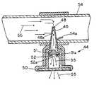
- FIG. 1is a partial cross-sectional exploded view showing drainage valve and pipe tap assembly of the present invention
- FIG. 2is a side view of an annular cone-shaped resilient drain plug
- FIG. 3is a top view of a drainage valve showing drainage valve handgrip supporting a drain pad
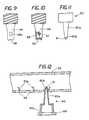
- FIG. 4is a side view showing an alternative embodiment of a drainage valve
- FIG. 5is a side view showing another alternative embodiment of a drainage valve
- FIG. 6is a cross-sectional view of the drainage valve of FIG. 5;
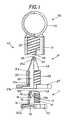
- FIG. 7is a partial cross-sectional view showing an alternative embodiment of a drainage valve and pipe tap assembly
- FIG. 8is a cross-sectional view showing the operation of a drainage valve and pipe tap assembly
- FIG. 9is a close-up view of the cutting tube of FIG. 8 having a first inlet and a second inlet;
- FIG. 10is a close-up view showing an alternative embodiment of a cutting tube having a lateral inlet comprising a screen
- FIG. 11is a close-up view of a tool comprising a shaft having a tapered body used for forming holes in a plastic pipe;
- FIG. 12shows a shaft in the process of forming a plurality of holes in a plastic pipe
- FIG. 13shows the attachment of a branching tube to a pipe wall.
- FIG. 1is a partial cross-sectional exploded view showing drainage valve and pipe tap assembly 10 of the present invention.
- FIG. 1shows drainage valve and pipe tap assembly 10 for a one-step connection of a branch line to a main line.
- the three componentsinclude a drainage valve 11 , a branch forming member or pipe tap 21 and a saddle tee 30 .
- all three componentsare made out of a polymer plastic or the like.
- Drainage valve 11comprises a valve body 12 having a first end 13 and a second end 14 .
- a passageway 15allowing for the flow of water from the first end 13 of valve body 12 to the second end 14 of valve body 12 .
- a drain plug support 16having an opening 16 a to allow water to flow therethrough.
- a screen 16 bhaving multiple openings that are sufficiently small to prevent the flow of dirt and other contaminants from flowing therethrough but sufficiently large to permit the flow of water therethrough.
- annular coneshaped resilient drain plug 18Located between drain plug support 16 and screen 16 b is an annular coneshaped resilient drain plug 18 .
- a male thread 17for rotational engagement.
- a drainage valve handgrip 20is shown integral to the second end 14 of the body 12 .
- Drainage valve handgrip 20enables a user to grasp and rotate drainage valve body 12 .
- Drainage valve handgrip 20has a hollow interior 20 a for support of a porous drain pad 19 .
- Drain pad 19prevents foreign particles from entering the passageway 15 of drainage body 12 while allowing for the drainage of water therethrough. Drainage pad 19 may be made from material such as Dacron or the like. This type of drainage valve is more thoroughly described in U.S. Pat. No. 4,890,640 and U.S. Pat. No. 5,080,527 and is hereby incorporated by reference.
- the pipe tap 21 of this inventionis a device that is capable of forming a hole in a sidewall of a pipe, while leaving a coupon integrally hinged but securely attached to the pipe wall, for creating a branch line.
- Pipe tap 21is shown in the present embodiment as having a first end 21 a and a second end 21 b .
- a chamber 22connecting the first end 21 a of the pipe tap 21 to the second end 21 b of the pipe tap 21 .
- a cutting tube 23Securely attached to first end 21 a of pipe tap 21 is a cutting tube 23 having a tapered end 24 .
- Located proximate tapered end 24 of cutting tube 23is at least one cutting tooth 26 for cutting a hole in the sidewall of a pipe.
- a first water inlet 25 and a second water inlet 25 afor receiving water therethrough.
- pipe tap handle 27Located at the second end 21 b of pipe tap 21 is a pipe tap handle 27 enabling a user to grasp and rotate pipe tap 21 .
- Located on an interior wall of pipe tap 21is a female thread 28 for rotationally engaging the male thread 17 of drainage valve 11 .
- Located on the exterior of pipe tap 21is a male thread 29 for rotational engagement with saddle tee 30 .
- Saddle tee 30comprises a pipe tap receptor 31 having a hollow interior for receiving pipe tap 21 and a pipe receptor 33 for engaging and securing pipe tap receptor 31 to a pipe wall.
- Pipe tap receptor 31includes a female thread 32 located on the interior wall of the receptor 31 allowing for the secure engagement with male thread 17 of pipe tap 21 .
- Pipe tap 21 and saddle tee 30are further described in U.S. patent application Ser. No. 60/183,612.
- the drainage valveis secured to the tap prior to forming the branch line.
- pipe receptor 33 of saddle tee 30first engages a pipe, securing pipe tap receptor 31 to the pipe.
- Pipe tap 21 with its male thread 29then engages the female thread 32 of pipe tap receptor 31 .
- the engagement between male thread 29 and the female thread 32provides for a secure engagement between pipe tap 21 and pipe tap receptor 31 .
- Pipe tap 21then is rotated into pipe tap receptor 31 by the rotation of pipe tap handle 27 .
- the rotation of pipe tap 21 into pipe tap receptor 31rotationally drives cutting tube 23 through the sidewall of the pipe to form a partial hole in the pipe wall by the cutting action of cutting tooth 26 while leaving a coupon 54 a (shown in FIG. 8) integrally hinged but securely attached to the pipe wall to maintain the coupon 54 a in an out-of-the-way condition within the passageway of the pipe.
- the interaction between the cutting tube 23 and the pipe sidewallare further described in U.S. patent application Ser. No. 60/183,612.
- the drainage valvesis secured to pipe tap after the pipe tap has been secured to the main line.
- pipe tap 21is secured to saddle tee 30
- drainage valve 11is inserted into the pipe tap 21 until its male thread 17 , engages the female thread 28 of the interior of wall of pipe tap 21 at the second end 21 b of pipe tap 21 .
- Drainage valve body 12is then rotated into pipe tap 21 to thereby completing formation of a freeze proof irrigation system.
- the rotational engagement between the male thread 17 of the valve body 12 and the female thread 28 of the pipe tap 21provides for a secure engagement between pipe tap 21 and drainage valve 11 .
- water from a pipelinefirst enters first water inlet 25 and second water inlet 25 a of pipe tap 21 .
- Waterthen flows through chamber 22 of pipe tap 21 and arrives at screen 16 b .
- the multiple openings of screen 16 ballow for the continual movement of the water to pass through screen 16 b but prevent sand, dirt particles, and other contaminates from passing therethrough.
- screen 16 bis shown in drainage valve 10 , such screen is not necessary as the screen on water inlet 25 a prevents sand, dirt, and other particles from passing through the drainage valve.
- Resilient drain plug 18is made of a resilient material such as rubber or the like.
- Resilient drain plug 18shown in FIG. 2, comprises a base 18 a and a set of legs 18 b .
- the fluid tight seal of opening 16 bis broken by resilient legs 18 b returning to their unflexed condition to thereby allow any water still remaining in the piping and drainage valve 11 to pass under resilient drain plug 18 and through opening 16 a.
- FIG. 3is a top view of drainage valve 11 showing drainage valve handgrip 20 with drain pad 19 located therein and partially bent to reveal the interior of drainage valve 11 and drain plug support 16 .
- FIG. 4is a side view showing an alternative embodiment of an insert 34 for a pipe tap.
- Insert 34comprises a hollow body 35 having a first end 35 a and a second end 35 b .
- body 35is shown in FIG. 4 to be tapered, alternative embodiments of drainage valve body 35 may be non-tapered.
- Located proximate first end 35 a of body 35is a screen 36 having multiple openings that are sufficiently small to prevent the flow of dirt and other contaminants but sufficiently large permit the flow of water through the screen.
- Screen 36is made of a polymer plastic and is form by either being molded with drainage valve 34 or is secured to first end 35 a of body 35 through such methods as heat sealing or adhesive bonding.
- Body support 37supports insert 34 within a pipe tap and are engageable to the female thread 28 of a pipe tap such as pipe tap 21 , shown in FIG. 1 .
- a pipe tapsuch as pipe tap 21 , shown in FIG. 1 .
- One of the benefits of the present embodimentis that since there is no male thread along the body 35 , the present embodiment allows insert 34 to be quickly attached to the pipe tap while still being capable of screening off various particles.
- a resilient drain plugsuch as shown in FIG. 2, can be mounted on a support surface therein to provide the necessary freeze protection for the system.
- FIG. 5is a side view and FIG. 6 is a cross-sectional view showing yet another alternative embodiment of a drainage valve 38 insert for a pipe tap.
- drainage valve 38includes a hollow body 39 having an inlet 40 and an outlet 41 .
- a screen 43having multiple openings that are sufficiently small to prevent the flow of dirt and other contaminants but sufficiently large to permit the automatic flow of water through the screen.
- Located on the exterior of hollow body 39is a male thread 39 a for rotationally engaging a female thread.
- Located within body 40is a passageway 42 allowing for the passage of water from inlet 40 to outlet 41 .
- a resilient drain plug 18having a base 18 a and a set of legs 18 b is shown in FIG.
- FIG. 7is a partial cross-sectional view showing a preferred embodiment of a drainage valve and pipe tap assembly 44 where the drainage valve is integral to the pipe tap to allow one to simultaneously form a branch line and freeze proof the system.
- the embodiment of pipe tap 44is similar in shape to the pipe tap 21 shown in FIG. 1 .
- Drainage valve and pipe tap assembly 44comprises a hollow body 45 having a first end 45 a and a second end 45 b . Attached to first end 45 a of hollow body 45 is a cutting tube 46 having a tapered end 46 a . Located proximate tapered end 46 a is at least one tooth 47 for cutting a hole in the sidewall of a pipe while leaving a coupon 54 a (shown in FIG. 8) integrally hinged but securely attached to the sidewall in an out-of-the-way condition. Located on the cutting tube are a first inlet 48 and a second inlet 48 a for receiving water.
- a handle 49Located at the second end 45 a of hollow body 45 is a handle 49 having a hollow interior 49 a .
- Handle 49is integral to hollow body 45 and is used for grasping and rotating hollow body 45 .
- hollow interior 49 ais shown supporting a drain pad 50 .
- Drain pad 50prevents foreign particles from entering hollow interior 49 a of hollow body 45 while allowing for the drainage of water therethrough.
- a drain plug support 52Located within hollow body 45 is a drain plug support 52 , having an opening 52 a , for support resilient drain plug 51 . Also located within hollow body 45 between first end 45 a and drain plug support 52 is a resilient drain plug 51 for blocking off the flow of water through opening 52 a under a water pressure and for allowing the draining of water therethrough when the water pressure is cut-off.
- FIG. 8is a cross-sectional view showing the operation of drainage valve and pipe tap assembly 44 .
- watershown by arrows 55
- waterfrom a pipeline 54 first enters first water inlet 48 and second water inlet 48 a of cutting tube 46 .
- Waterthen flows through cutting tube 46 after which it is met by resilient drain plug 51 .
- the water pressure created by the flow of water into cutting tube 46acts on resilient drain plug 51 to push resilient drain plug 51 against drain plug support 52 .
- the force that resilient drain plug 51 acts against drain plug support 52causes resilient legs 51 a to flex to thereby provide for a fluid tight seal of opening 52 a to thereby blocking off the flow of water therethrough.
- the fluid tight seal of opening 52 ais broken by resilient legs 51 a returning to their unflexed condition to thereby allow any water still remaining in the assembly 44 to pass under resilient drain plug 51 and out of assembly 44 .
- Allowing water to escape from assembly 44prevents water in the pipes and assembly 44 from freezing and expanding, causing possible damages to the pipes and assembly 44 in regions where temperatures often drop below the water freezing point.
- the draining operationis further described in U.S. Pat. No. 4,890,640 and U.S. Pat. No. 5,080,527, which are incorporated by reference.
- FIGS. 9 and 10are close-up views showing alternative embodiments of a cutting tube with FIG. 10 also showing a partial cross-sectional view of the tapered end 58 .
- the embodiment of cutting tube 46 in FIGS. 8 and 9shows cutting tube 46 having first inlet 48 and second inlet 48 a for receiving water therethrough.
- the embodiment of cutting tube 56 in FIG. 10shows cutting tube 56 as having just one lateral inlet comprising a screen 57 for receiving water therethrough.
- Screen 57has multiple openings that are sufficiently small to prevent the flow of dirt and other contaminants but sufficiently large permit the automatic flow of water through the screen.
- Screen 57is made of a polymer plastic and can be formed by being molded with pipe cutting tube 56 or can be made and attached to cutting tube 56 through such methods as heat sealing or adhesive bonding. Although one screen is shown in the present embodiment, alternative embodiment may include more or less screens.
- the cutting tubesare shown having a first inlet 25 , 48 for receiving water therethrough.
- the region of cutting tube 56 comparable to the first inlet of FIGS. 1, 7 , 8 and 9 or the tip 59 of the cutting tube 56is closed off, resulting in the flow of water through the lateral inlet of cutting tube 46 .
- dirt and other contaminantsmay be filtered by screen 57 to thereby further reduce the clogging of the valve and pipe tap assembly.
- FIG. 11is a close-up view of a tool, comprising a shaft 60 having a tapered body 60 a , used for forming holes in a plastic pipe without leaving the tool therein.
- This toolis ideal for projects in which holes are required to be formed in a pipe for attachment to a separate assembly or in projects requiring the formation of a plurality of holes in a pipe such as, for example, in the formation of a drip irrigation system.
- FIG. 11shows shaft 60 having one cutting tooth 61 extending outwardly from a first end 60 b of shaft 60 for forming a hole in a pipe
- alternative embodiments of shaft 60may comprise numerous cutting teeth for forming a hole in the pipe.
- FIG. 12shows shaft 60 in the process of forming a plurality of holes 69 in a plastic pipe 62 .
- shaft 60may have a hollow or a solid body.
- shaft 60is shown in FIG. 12 forming the plurality of holes 69 in the sidewall of pipe 62 without the use of a saddle tee, shaft 60 can also be used with a saddle tee to form the holes when so desired.
- cutting tooth 61 of shaft 60first engages the sidewall of pipe 62 , pipe 62 comprising a plastic material such as polyethylene, PVC, or the like.
- a userthen uses his or her hands to apply axial force to shaft 60 while simultaneously rotationally driving shaft 60 into the sidewall of pipe 62 .
- a usercan rotationally drive shaft 60 into the sidewall of pipe 62 by rotating shaft 60 with the user's hands.
- the embodiment of FIG. 12includes a shaft handle 68 integral to a second end 60 c of shaft 60 , handle 68 enabling a user to grasp tapered body 60 a of shaft 60 for rotationally driving shaft 60 through the sidewall of pipe 62 to form a hole 63 in the sidewall of pipe 62 .
- the axial force applied by the user against the sidewall of pipe 62 along with the simultaneous rotation of shaft 60causes cutting tooth 61 to form hole 63 in the sidewall of pipe 62 while leaving a coupon 62 a integrally hinged but securely attached to the sidewall of pipe 62 to maintain coupon 62 a in an out-of-the-way condition within the passageway of the pipe.
- tapered body 60 a of shaft 60is driven further into hole 63 thereby spreading hole 63 further apart.
- An advantage of the present inventionis that unlike other known hole forming tools which leaves excess materials in the pipe after the holes are formed, the present invention forces out the piping materials thereby leaving the pipe with just coupons 62 a in an out-of-the-way condition after the holes are formed.
- FIG. 13shows pipe 62 with hole 63 formed in the sidewall of pipe 62 by shaft 60 of FIGS. 11 and 12.
- an elastomer sealing ringsuch as an O-ring 64 , having a first face 64 a and a second face 64 b , is then placed around hole 63 with the first face 64 a of O-ring 64 engaging the sidewall of pipe 62 , as shown in FIG. 13 .
- FIG. 13also shows a branching tube 65 having a preformed hole 66 located in a wall surface of tube 65 .
- branching tube 65Once first face 64 a of O-ring 64 engages the sidewall of pipe 62 branching tube 65 is then attached to the second face 64 b of O-ring 64 with preformed hole 66 of branching tube 65 in a water receiving alignment with hole 63 of pipe 62 .
- a fastening device 67such as a clamp, is then attached to the pipe and branching tube assembly to maintain the connection of the pipe and branching tube assembly. The attachment of the fastening device 67 results in O-ring 66 forming a leak proof connection between pipe 64 and branching tube 65 .
- the present methodcan be use with various types of piping
- the present methodwith its use of O-ring 64 , is well suited for use with PVC piping since PVC piping maintain their shape, allowing for the compression of O-ring 64 to thereby form a leak proof connection.
- the present inventionincludes a method of forming a connection of a branch line to a main line comprising the steps of: (1) engaging a cutting tooth 61 of a tapered shaft 60 to a sidewall of a pipe 62 ; (2) applying axial force to the shaft 60 while simultaneously rotating a shaft handle 68 to rotationally drive the shaft 60 through the sidewall of the pipe 62 to form a hole 63 in the sidewall of the pipe 62 while leaving a coupon 62 a integrally hinged but securely attached to the sidewall of pipe 62 to maintain the coupon 62 a in an out-of-the-way condition within the passageway of the pipe; (3) removing the shaft 60 from the sidewall of the pipe 62 ; (4) placing a first face 64 a of an O-ring 64 around the hole 63 of the pipe 62 formed by the shaft 60 ; (5) aligning a preformed hole 66 in a branching tube 65 to the hole 63 of the pipe 62 formed by the shaft 60 ; (6) attaching the branching tube 65 to a
- the present inventionalso includes a method of making a drainage valve and pipe tap assembly comprising the steps of: (1) forming a drainage valve 38 having body 39 , an inlet 40 , an outlet 41 , a passageway 42 , a male thread 39 a located on an exterior of the drainage valve 40 , and a screen 43 and resilient drain plug 18 located therein; (2) forming a pipe tap 21 having a first end 21 a , a second end 21 b , a chamber 22 connecting the first end 21 a of pipe tap 21 to the second end 21 b of the pipe tap 21 , a female thread 28 located on an interior wall of the pipe tap 21 , a handle 20 having a hollow interior 20 a located at the second end 21 b of pipe tap 21 , and a cutting tube 23 located at the first end 21 a of pipe tap 21 having a tapered end 24 with at least one cutting tooth 26 ; and (3) attaching the drainage valve 38 to the pipe tap 21 by inserting the inlet 40 of the drainage valve 39 into the second end 21 b of the
- the method of making a drainage valve and pipe tap assemblyalso include the step of: (1) attaching the drainage valve 39 to the pipe tap 21 before cutting a hole in a pipe; (2) or attaching the drainage valve 39 to the pipe tap 21 after cutting a hole in the pipe; (3) inserting the drainage valve 39 completely within the pipe tap 21 ; and (4) covering the hollow interior of the pipe tap 21 with a drain pad 50 to prevent foreign particles from entering the drainage valve and pipe tap assembly.
- the method of making a drainage valve and pipe tap assemblyalso include the step of attaching a handgrip 20 having a hollow interior 20 a with a drain pad 19 placed over the hollow interior 20 a of the handgrip 20 to prevent foreign particles from entering the drainage valve and pipe tap assembly 10 .
- the present inventionalso includes an insitu method of forming a freeze proof drain comprising the steps of: (1) attaching a housing or saddle 30 having pipe a receptor 33 to a pipe; (2) attaching a pipe tap 21 to the housing 30 ; (3) forming a hole in a sidewall of the pipe by rotationally driving a cutting tube 23 of the pipe tap 21 through a sidewall the pipe; and (4) inserting a drainage valve 11 having a resilient drain plug 18 located therein into a chamber 22 in pipe tap 21 to form a freeze proof drain.
- the present inventionalso includes an insitu method of forming a freeze proof drain system comprising (1) attaching a tap housing 30 to a pipe; (2) extending a tap 21 through a sidewall of the pipe; and (3) inserting a drainage valve 11 into the tap 21 to form a freeze proof drain system.
- the present inventionincludes the method of forming a freeze proof drain system at the same time the branch line is formed by having the drainage valve integral to or carried by the tap.
Landscapes
- Engineering & Computer Science (AREA)
- General Engineering & Computer Science (AREA)
- Mechanical Engineering (AREA)
- Branch Pipes, Bends, And The Like (AREA)
Abstract
Description
Claims (25)
Priority Applications (1)
| Application Number | Priority Date | Filing Date | Title |
|---|---|---|---|
| US10/005,258US6681796B2 (en) | 2000-02-18 | 2001-12-03 | Drainage valve pipe tap assembly |
Applications Claiming Priority (2)
| Application Number | Priority Date | Filing Date | Title |
|---|---|---|---|
| US18361200P | 2000-02-18 | 2000-02-18 | |
| US10/005,258US6681796B2 (en) | 2000-02-18 | 2001-12-03 | Drainage valve pipe tap assembly |
Publications (2)
| Publication Number | Publication Date |
|---|---|
| US20020040732A1 US20020040732A1 (en) | 2002-04-11 |
| US6681796B2true US6681796B2 (en) | 2004-01-27 |
Family
ID=26674133
Family Applications (1)
| Application Number | Title | Priority Date | Filing Date |
|---|---|---|---|
| US10/005,258Expired - LifetimeUS6681796B2 (en) | 2000-02-18 | 2001-12-03 | Drainage valve pipe tap assembly |
Country Status (1)
| Country | Link |
|---|---|
| US (1) | US6681796B2 (en) |
Cited By (23)
| Publication number | Priority date | Publication date | Assignee | Title |
|---|---|---|---|---|
| US20050056342A1 (en)* | 2003-09-17 | 2005-03-17 | Adam Awad | Apparatus and method for dispensing fluids into an air intake |
| US6886585B1 (en)* | 2004-06-25 | 2005-05-03 | The Patent Store Llc | Soft grip drain |
| US20050194469A1 (en)* | 2004-03-02 | 2005-09-08 | Abed Masarwa | Irrigation pipe |
| US20060103131A1 (en)* | 2004-03-02 | 2006-05-18 | Abed Masarwa | Irrigation pipe |
| US20060169805A1 (en)* | 2005-01-28 | 2006-08-03 | Rajiv Dabir | Saddle tee and tool for irrigation lines |
| US7832420B2 (en) | 2007-12-07 | 2010-11-16 | Orbit Irrigation Products, Inc. | Saddle tee |
| AU2012200500B2 (en)* | 2004-03-02 | 2013-06-13 | Netafim Ltd. | Irrigation pipe |
| US20130183097A1 (en)* | 2012-01-17 | 2013-07-18 | Wayne L. Scantling | Modular subterranean irrigation system and method of installation |
| US8651454B1 (en) | 2011-04-06 | 2014-02-18 | Paul Thompson | Efficient drain systems |
| US20150082953A1 (en)* | 2013-09-20 | 2015-03-26 | L. Herbert King, Jr. | Pocket field tool |
| US20150167884A1 (en)* | 2013-12-13 | 2015-06-18 | Thomas A. King | Fittings for pipes, and presses for installing the fittings to pipes |
| US20150300543A1 (en)* | 2014-04-21 | 2015-10-22 | Blazing Products, Inc. | Drain fittings for irrigation systems |
| US20150346734A1 (en)* | 2014-06-02 | 2015-12-03 | Bilfinger Water Technologies, Inc. | Controller for vacuum sewage system |
| USD748442S1 (en)* | 2014-09-18 | 2016-02-02 | Daniel L White | Vehicle oil filter drain tool |
| CN105605361A (en)* | 2016-02-17 | 2016-05-25 | 成都佳美嘉科技有限公司 | Universal water escape valve pipeline structure |
| US20160297296A1 (en)* | 2013-12-09 | 2016-10-13 | Raval A.C.S. Ltd. | Draining device |
| US20170016547A1 (en)* | 2015-07-16 | 2017-01-19 | Goodrich Corporation | Threaded adapter assembly and fuse plug |
| US9661807B2 (en) | 2012-05-24 | 2017-05-30 | Rain Bird Corporation | Conduit with connector and assembly thereof |
| US9668431B2 (en) | 2013-11-22 | 2017-06-06 | Rain Bird Corporation | Conduit with connector and assembly thereof |
| US9938680B2 (en) | 2014-11-21 | 2018-04-10 | Duane K. Smith | Fittings for irrigation systems |
| US10086690B2 (en) | 2014-09-29 | 2018-10-02 | Raval A.C.S. Ltd. | Draining arrangement |
| US10537073B2 (en) | 2012-05-24 | 2020-01-21 | Rain Bird Corporation | Conduit with connector and assembly thereof |
| CN110998163A (en)* | 2017-06-27 | 2020-04-10 | 韦尔梅专利有限公司 | Device for draining or removing water from water pipes |
Families Citing this family (9)
| Publication number | Priority date | Publication date | Assignee | Title |
|---|---|---|---|---|
| FR3054609A1 (en)* | 2016-07-29 | 2018-02-02 | Plastic Omnium Advanced Innovation & Res | VENTILATION FLOW REGULATOR FOR A PRESSURIZED VEHICLE TANK. |
| WO2018136563A1 (en)* | 2017-01-18 | 2018-07-26 | Aquor Water Systems, Incorporated | Anti-freezing water valve with optional anti-siphon assembly and water-valve accessories |
| US11186970B2 (en) | 2017-03-29 | 2021-11-30 | Aquor Water Systems, Incorporated | Anti-freezing water valve configured for underground (buried) use and with optional anti-siphon assembly, and water-valve accessories |
| WO2018183758A1 (en) | 2017-03-29 | 2018-10-04 | Aquor Water Systems, Incorporated | Removable fire-suppression sprinkler head with a water-intake valve |
| USD920383S1 (en)* | 2019-02-15 | 2021-05-25 | Scott J. Macco | Vehicle oil pan drain key |
| USD912705S1 (en)* | 2019-02-25 | 2021-03-09 | Scott J. Macco | Vehicle oil pan drain plug |
| USD901541S1 (en)* | 2019-03-05 | 2020-11-10 | RB Distribution, Inc. | Petcock |
| CN113028106A (en)* | 2021-04-28 | 2021-06-25 | 河北亚大汽车塑料制品有限公司 | Three-way one-way valve for vacuum braking of automobile |
| USD975745S1 (en)* | 2022-01-13 | 2023-01-17 | Guangzhou Issyzone Technology Co., Limited | Oil drain plug |
Citations (21)
| Publication number | Priority date | Publication date | Assignee | Title |
|---|---|---|---|---|
| US3516426A (en)* | 1967-12-11 | 1970-06-23 | Du Pont | Method for installing a thermoplastic pipe branching saddle on an operating thermoplastic main |
| US3905718A (en)* | 1973-12-18 | 1975-09-16 | Mueller Co | Driving tool |
| US3976091A (en)* | 1975-05-29 | 1976-08-24 | Hutton Walter C | Pipe tapping tool |
| US4540011A (en)* | 1982-08-25 | 1985-09-10 | Hotpoint Limited | Method and device for forming a branch connection in a pipe |
| US4574443A (en) | 1984-06-21 | 1986-03-11 | Exxon Research And Engineering Co. | Pipe punch device |
| US4680848A (en)* | 1985-11-25 | 1987-07-21 | Goldner Erwin P | Pipe tapping tool |
| US4890640A (en)* | 1988-07-05 | 1990-01-02 | King Lloyd H Sr | Drainage valve |
| US5076318A (en) | 1990-08-23 | 1991-12-31 | Phillips Petroleum Company | Tapping tee cutter for plastic pipe |
| US5080527A (en)* | 1990-06-11 | 1992-01-14 | King Lloyd H Sr | Drain apparatus |
| US5105844A (en) | 1990-09-24 | 1992-04-21 | King Lloyd H Sr | Two step branch forming attachment |
| US5241981A (en) | 1992-05-07 | 1993-09-07 | Conbraco Industries, Inc. | Self-tapping pressure relief valve |
| US5345964A (en) | 1992-05-30 | 1994-09-13 | Friatec Ag Keramik- Und Kunststoffwerke | Pipe piercing fitting and valve |
| US5425395A (en) | 1994-09-13 | 1995-06-20 | Perfection Corporation | Tapping tee assembly |
| US5577529A (en) | 1995-01-19 | 1996-11-26 | Plasson Maagan Michael Industries Ltd. | Tapping fittings |
| US5694972A (en) | 1996-06-27 | 1997-12-09 | Tom King Harmony Products, Inc. | Saddle tee for irrigation lines |
| US5732732A (en) | 1995-07-09 | 1998-03-31 | Plasson Maagan Michael Industries Ltd | Tapping fitting |
| US5896885A (en) | 1996-06-11 | 1999-04-27 | Phillips Petroleum Company | Tapping saddle pipe fitting |
| US5964240A (en) | 1998-06-15 | 1999-10-12 | Pressurised Pipe Connectors Ltd | Pipe tapping |
| US5967168A (en) | 1997-04-10 | 1999-10-19 | Waterworks Technology Development Organization Co., Ltd. | Method of connecting branch pipe |
| US6012475A (en) | 1998-06-03 | 2000-01-11 | Delta Engineering Holdings Limited | Self-piercing valve assembly |
| US6216723B1 (en) | 1999-11-05 | 2001-04-17 | Tom King Harmony Products, Inc. | Self-tapping tee |
- 2001
- 2001-12-03USUS10/005,258patent/US6681796B2/ennot_activeExpired - Lifetime
Patent Citations (21)
| Publication number | Priority date | Publication date | Assignee | Title |
|---|---|---|---|---|
| US3516426A (en)* | 1967-12-11 | 1970-06-23 | Du Pont | Method for installing a thermoplastic pipe branching saddle on an operating thermoplastic main |
| US3905718A (en)* | 1973-12-18 | 1975-09-16 | Mueller Co | Driving tool |
| US3976091A (en)* | 1975-05-29 | 1976-08-24 | Hutton Walter C | Pipe tapping tool |
| US4540011A (en)* | 1982-08-25 | 1985-09-10 | Hotpoint Limited | Method and device for forming a branch connection in a pipe |
| US4574443A (en) | 1984-06-21 | 1986-03-11 | Exxon Research And Engineering Co. | Pipe punch device |
| US4680848A (en)* | 1985-11-25 | 1987-07-21 | Goldner Erwin P | Pipe tapping tool |
| US4890640A (en)* | 1988-07-05 | 1990-01-02 | King Lloyd H Sr | Drainage valve |
| US5080527A (en)* | 1990-06-11 | 1992-01-14 | King Lloyd H Sr | Drain apparatus |
| US5076318A (en) | 1990-08-23 | 1991-12-31 | Phillips Petroleum Company | Tapping tee cutter for plastic pipe |
| US5105844A (en) | 1990-09-24 | 1992-04-21 | King Lloyd H Sr | Two step branch forming attachment |
| US5241981A (en) | 1992-05-07 | 1993-09-07 | Conbraco Industries, Inc. | Self-tapping pressure relief valve |
| US5345964A (en) | 1992-05-30 | 1994-09-13 | Friatec Ag Keramik- Und Kunststoffwerke | Pipe piercing fitting and valve |
| US5425395A (en) | 1994-09-13 | 1995-06-20 | Perfection Corporation | Tapping tee assembly |
| US5577529A (en) | 1995-01-19 | 1996-11-26 | Plasson Maagan Michael Industries Ltd. | Tapping fittings |
| US5732732A (en) | 1995-07-09 | 1998-03-31 | Plasson Maagan Michael Industries Ltd | Tapping fitting |
| US5896885A (en) | 1996-06-11 | 1999-04-27 | Phillips Petroleum Company | Tapping saddle pipe fitting |
| US5694972A (en) | 1996-06-27 | 1997-12-09 | Tom King Harmony Products, Inc. | Saddle tee for irrigation lines |
| US5967168A (en) | 1997-04-10 | 1999-10-19 | Waterworks Technology Development Organization Co., Ltd. | Method of connecting branch pipe |
| US6012475A (en) | 1998-06-03 | 2000-01-11 | Delta Engineering Holdings Limited | Self-piercing valve assembly |
| US5964240A (en) | 1998-06-15 | 1999-10-12 | Pressurised Pipe Connectors Ltd | Pipe tapping |
| US6216723B1 (en) | 1999-11-05 | 2001-04-17 | Tom King Harmony Products, Inc. | Self-tapping tee |
Cited By (36)
| Publication number | Priority date | Publication date | Assignee | Title |
|---|---|---|---|---|
| US6948642B2 (en)* | 2003-09-17 | 2005-09-27 | Adam Awad | Apparatus and method for dispensing fluids into an air intake |
| US20050056342A1 (en)* | 2003-09-17 | 2005-03-17 | Adam Awad | Apparatus and method for dispensing fluids into an air intake |
| US8672240B2 (en) | 2004-03-02 | 2014-03-18 | Netafim, Ltd. | Irrigation pipe |
| US20050194469A1 (en)* | 2004-03-02 | 2005-09-08 | Abed Masarwa | Irrigation pipe |
| US20060103131A1 (en)* | 2004-03-02 | 2006-05-18 | Abed Masarwa | Irrigation pipe |
| US7588201B2 (en)* | 2004-03-02 | 2009-09-15 | Netafim Ltd | Irrigation pipe |
| AU2012200500B2 (en)* | 2004-03-02 | 2013-06-13 | Netafim Ltd. | Irrigation pipe |
| AU2010201524B2 (en)* | 2004-03-02 | 2011-12-08 | Netafim Ltd. | Irrigation pipe |
| US6886585B1 (en)* | 2004-06-25 | 2005-05-03 | The Patent Store Llc | Soft grip drain |
| US20060169805A1 (en)* | 2005-01-28 | 2006-08-03 | Rajiv Dabir | Saddle tee and tool for irrigation lines |
| US7219684B2 (en) | 2005-01-28 | 2007-05-22 | Rain Bird Corporation | Saddle tee and tool for irrigation lines |
| US8196599B2 (en) | 2007-12-07 | 2012-06-12 | Orbit Irrigation Products, Inc. | Saddle tee |
| US20110127764A1 (en)* | 2007-12-07 | 2011-06-02 | Scot Hoskisson | Saddle tee |
| US7832420B2 (en) | 2007-12-07 | 2010-11-16 | Orbit Irrigation Products, Inc. | Saddle tee |
| US8651454B1 (en) | 2011-04-06 | 2014-02-18 | Paul Thompson | Efficient drain systems |
| US20130183097A1 (en)* | 2012-01-17 | 2013-07-18 | Wayne L. Scantling | Modular subterranean irrigation system and method of installation |
| US10537073B2 (en) | 2012-05-24 | 2020-01-21 | Rain Bird Corporation | Conduit with connector and assembly thereof |
| US9661807B2 (en) | 2012-05-24 | 2017-05-30 | Rain Bird Corporation | Conduit with connector and assembly thereof |
| US9358676B2 (en)* | 2013-09-20 | 2016-06-07 | Patent Store Llc | Pocket field tool |
| US20150082953A1 (en)* | 2013-09-20 | 2015-03-26 | L. Herbert King, Jr. | Pocket field tool |
| US9668431B2 (en) | 2013-11-22 | 2017-06-06 | Rain Bird Corporation | Conduit with connector and assembly thereof |
| US20160297296A1 (en)* | 2013-12-09 | 2016-10-13 | Raval A.C.S. Ltd. | Draining device |
| US10183574B2 (en)* | 2013-12-09 | 2019-01-22 | Raval A.C.S. Ltd. | Draining device |
| US20150167884A1 (en)* | 2013-12-13 | 2015-06-18 | Thomas A. King | Fittings for pipes, and presses for installing the fittings to pipes |
| US9599268B2 (en)* | 2013-12-13 | 2017-03-21 | Thomas A. King | Fittings for pipes, and presses for installing the fittings to pipes |
| US20150300543A1 (en)* | 2014-04-21 | 2015-10-22 | Blazing Products, Inc. | Drain fittings for irrigation systems |
| US9835282B2 (en)* | 2014-04-21 | 2017-12-05 | Blazing Products, Inc. | Drain fittings for irrigation systems |
| US10001787B2 (en)* | 2014-06-02 | 2018-06-19 | Aqseptence Group, Inc. | Controller for vacuum sewage system |
| US20150346734A1 (en)* | 2014-06-02 | 2015-12-03 | Bilfinger Water Technologies, Inc. | Controller for vacuum sewage system |
| USD748442S1 (en)* | 2014-09-18 | 2016-02-02 | Daniel L White | Vehicle oil filter drain tool |
| US10086690B2 (en) | 2014-09-29 | 2018-10-02 | Raval A.C.S. Ltd. | Draining arrangement |
| US9938680B2 (en) | 2014-11-21 | 2018-04-10 | Duane K. Smith | Fittings for irrigation systems |
| US9915366B2 (en)* | 2015-07-16 | 2018-03-13 | Goodrich Corporation | Threaded adapter assembly and fuse plug |
| US20170016547A1 (en)* | 2015-07-16 | 2017-01-19 | Goodrich Corporation | Threaded adapter assembly and fuse plug |
| CN105605361A (en)* | 2016-02-17 | 2016-05-25 | 成都佳美嘉科技有限公司 | Universal water escape valve pipeline structure |
| CN110998163A (en)* | 2017-06-27 | 2020-04-10 | 韦尔梅专利有限公司 | Device for draining or removing water from water pipes |
Also Published As
| Publication number | Publication date |
|---|---|
| US20020040732A1 (en) | 2002-04-11 |
Similar Documents
| Publication | Publication Date | Title |
|---|---|---|
| US6681796B2 (en) | Drainage valve pipe tap assembly | |
| US6708717B1 (en) | Flushing system for air conditioning drainage pipes | |
| US7686235B2 (en) | Check valve assembly for controlling the flow of pressurized fluids | |
| US4730636A (en) | Valve and tapping tee apparatus and method | |
| US4646775A (en) | Vacuum breaker | |
| US7721754B2 (en) | Tapping tee assembly with cap assembly | |
| US7472912B2 (en) | Tear-out coupling and water line | |
| US8439060B1 (en) | Attachable drain collar for plumbing system couplings | |
| US8286275B2 (en) | Drain clean-out assembly and method of using | |
| CA2030132A1 (en) | Self-draining backflow prevention valves | |
| US5123627A (en) | Condensate drain fitting with check valve and stepped diameters to fit different pipe sizes | |
| JP6234671B2 (en) | Branch pipe removing device and method | |
| US5318075A (en) | Drip stop plug | |
| EP1564474B1 (en) | No interrupt service tee and method | |
| US6508267B1 (en) | Plumbing tool and method for repairing a pipe therewith | |
| US5662358A (en) | Branch-off connection | |
| GB2335959A (en) | Hose coupling | |
| US20040261864A1 (en) | Flushing plug for water control valve | |
| US5901731A (en) | Reverse osmosis drain coupling and method of installing | |
| JP4499400B2 (en) | Plumbing tool and method for repairing pipes using the same | |
| GB2432405A (en) | Valve | |
| US20070221272A1 (en) | Water hose purging device | |
| JP6385547B2 (en) | Branch pipe removing device and method | |
| US10309540B2 (en) | Valves for controlling fluid passage | |
| US6116262A (en) | Plumbing coupling and method of use |
Legal Events
| Date | Code | Title | Description |
|---|---|---|---|
| STCF | Information on status: patent grant | Free format text:PATENTED CASE | |
| FPAY | Fee payment | Year of fee payment:4 | |
| FPAY | Fee payment | Year of fee payment:8 | |
| FPAY | Fee payment | Year of fee payment:12 | |
| AS | Assignment | Owner name:THE PATENT STORE LLC, MISSOURI Free format text:ASSIGNMENT OF ASSIGNORS INTEREST;ASSIGNOR:KING, LLOYD HERBERT, JR.;REEL/FRAME:045845/0120 Effective date:20011203 | |
| AS | Assignment | Owner name:ROYAL BANK OF CANADA, AS ADMINISTRATIVE AGENT, CANADA Free format text:FIRST LIEN INTELLECTUAL PROPERTY SECURITY AGREEMENT;ASSIGNOR:KING TECHNOLOGY OF MISSOURI, LLC;REEL/FRAME:046216/0193 Effective date:20180522 Owner name:ROYAL BANK OF CANADA, AS ADMINISTRATIVE AGENT, CAN Free format text:FIRST LIEN INTELLECTUAL PROPERTY SECURITY AGREEMENT;ASSIGNOR:KING TECHNOLOGY OF MISSOURI, LLC;REEL/FRAME:046216/0193 Effective date:20180522 | |
| AS | Assignment | Owner name:WILMINGTON TRUST, NATIONAL ASSOCIATION, AS ADMINISTRATIVE AGENT, DELAWARE Free format text:SECURITY INTEREST;ASSIGNOR:KING TECHNOLOGY OF MISSOURI, LLC;REEL/FRAME:045897/0977 Effective date:20180522 Owner name:WILMINGTON TRUST, NATIONAL ASSOCIATION, AS ADMINIS Free format text:SECURITY INTEREST;ASSIGNOR:KING TECHNOLOGY OF MISSOURI, LLC;REEL/FRAME:045897/0977 Effective date:20180522 | |
| AS | Assignment | Owner name:KING TECHNOLOGY OF MISSOURI, LLC, MISSOURI Free format text:TERMINATION AND RELEASE OF SECURITY INTEREST IN INTELLECTUAL PROPERTY;ASSIGNOR:ROYAL BANK OF CANADA;REEL/FRAME:046761/0595 Effective date:20180809 Owner name:KING TECHNOLOGY OF MISSOURI, LLC, MISSOURI Free format text:TERMINATION AND RELEASE OF SECURITY INTEREST IN SECOND LIEN INTELLECTUAL PROPERTY COLLATERAL;ASSIGNOR:WILMINGTON TRUST, NATIONAL ASSOCIATION, AS ADMINISTRATIVE AGENT;REEL/FRAME:046762/0718 Effective date:20180809 | |
| AS | Assignment | Owner name:JPMORGAN CHASE BANK, N.A., ILLINOIS Free format text:SECURITY INTEREST;ASSIGNOR:THE PATENT STORE, LLC;REEL/FRAME:048141/0202 Effective date:20190123 | |
| AS | Assignment | Owner name:THE PATENT STORE, LLC, MISSOURI Free format text:CORRECTIVE ASSIGNMENT TO CORRECT THE CORRECT NAME OF ASSIGNEE PREVIOUSLY RECORDED AT REEL: 045845 FRAME: 0120`. ASSIGNOR(S) HEREBY CONFIRMS THE ASSIGNMENT;ASSIGNOR:KING, LLOYD HERBERT, JR.;REEL/FRAME:050072/0633 Effective date:20011203 | |
| AS | Assignment | Owner name:ANTARES CAPITAL LP, AS AGENT, ILLINOIS Free format text:SECURITY INTEREST;ASSIGNORS:ECM INDUSTRIES, LLC;KING TECHNOLOGY OF MISSOURI, LLC;THE PATENT STORE, LLC;REEL/FRAME:051404/0833 Effective date:20191223 | |
| AS | Assignment | Owner name:THE PATENT STORE, LLC, MISSOURI Free format text:RELEASE OF SECURITY INTEREST IN PATENTS;ASSIGNOR:JPMORGAN CHASE BANK, N.A.;REEL/FRAME:051446/0840 Effective date:20191223 | |
| AS | Assignment | Owner name:ANTARES CAPITAL LP, AS AGENT, ILLINOIS Free format text:RELEASE BY SECURED PARTY;ASSIGNORS:ECM INDUSTRIES, LLC;KING TECHNOLOGY OF MISSOURI, LLC;THE PATENT STORE, LLC;REEL/FRAME:064501/0438 Effective date:20230518 | |
| AS | Assignment | Owner name:THE PATENT STORE, LLC, MISSOURI Free format text:CORRECTIVE ASSIGNMENT TO CORRECT THE CONVEY PARTY TO ANTARES CAPITAL LP AND RECEIVE PARTY TO ECM INDUSTRIES, LLC, KING TECHNOLOGY OF MISSOURI, LLC, THE PATENT STORE, LLC PREVIOUSLY RECORDED ON REEL 064501 FRAME 0438. ASSIGNOR(S) HEREBY CONFIRMS THE RELEASE OF SECURITY INTEREST;ASSIGNOR:ANTARES CAPITAL LP, AS AGENT;REEL/FRAME:064718/0894 Effective date:20230518 Owner name:KING TECHNOLOGY OF MISSOURI, LLC, MISSOURI Free format text:CORRECTIVE ASSIGNMENT TO CORRECT THE CONVEY PARTY TO ANTARES CAPITAL LP AND RECEIVE PARTY TO ECM INDUSTRIES, LLC, KING TECHNOLOGY OF MISSOURI, LLC, THE PATENT STORE, LLC PREVIOUSLY RECORDED ON REEL 064501 FRAME 0438. ASSIGNOR(S) HEREBY CONFIRMS THE RELEASE OF SECURITY INTEREST;ASSIGNOR:ANTARES CAPITAL LP, AS AGENT;REEL/FRAME:064718/0894 Effective date:20230518 Owner name:ECM INDUSTRIES, LLC, WISCONSIN Free format text:CORRECTIVE ASSIGNMENT TO CORRECT THE CONVEY PARTY TO ANTARES CAPITAL LP AND RECEIVE PARTY TO ECM INDUSTRIES, LLC, KING TECHNOLOGY OF MISSOURI, LLC, THE PATENT STORE, LLC PREVIOUSLY RECORDED ON REEL 064501 FRAME 0438. ASSIGNOR(S) HEREBY CONFIRMS THE RELEASE OF SECURITY INTEREST;ASSIGNOR:ANTARES CAPITAL LP, AS AGENT;REEL/FRAME:064718/0894 Effective date:20230518 |