US6681575B2 - Turbocompound internal combustion engine - Google Patents
Turbocompound internal combustion engineDownload PDFInfo
- Publication number
- US6681575B2 US6681575B2US09/971,817US97181701AUS6681575B2US 6681575 B2US6681575 B2US 6681575B2US 97181701 AUS97181701 AUS 97181701AUS 6681575 B2US6681575 B2US 6681575B2
- Authority
- US
- United States
- Prior art keywords
- turbine
- engine
- auxiliary turbine
- speed
- range
- Prior art date
- Legal status (The legal status is an assumption and is not a legal conclusion. Google has not performed a legal analysis and makes no representation as to the accuracy of the status listed.)
- Expired - Fee Related
Links
Images


Classifications
- F—MECHANICAL ENGINEERING; LIGHTING; HEATING; WEAPONS; BLASTING
- F02—COMBUSTION ENGINES; HOT-GAS OR COMBUSTION-PRODUCT ENGINE PLANTS
- F02B—INTERNAL-COMBUSTION PISTON ENGINES; COMBUSTION ENGINES IN GENERAL
- F02B37/00—Engines characterised by provision of pumps driven at least for part of the time by exhaust
- F02B37/12—Control of the pumps
- F02B37/24—Control of the pumps by using pumps or turbines with adjustable guide vanes
- F—MECHANICAL ENGINEERING; LIGHTING; HEATING; WEAPONS; BLASTING
- F02—COMBUSTION ENGINES; HOT-GAS OR COMBUSTION-PRODUCT ENGINE PLANTS
- F02B—INTERNAL-COMBUSTION PISTON ENGINES; COMBUSTION ENGINES IN GENERAL
- F02B37/00—Engines characterised by provision of pumps driven at least for part of the time by exhaust
- F02B37/005—Exhaust driven pumps being combined with an exhaust driven auxiliary apparatus, e.g. a ventilator
- F—MECHANICAL ENGINEERING; LIGHTING; HEATING; WEAPONS; BLASTING
- F02—COMBUSTION ENGINES; HOT-GAS OR COMBUSTION-PRODUCT ENGINE PLANTS
- F02B—INTERNAL-COMBUSTION PISTON ENGINES; COMBUSTION ENGINES IN GENERAL
- F02B41/00—Engines characterised by special means for improving conversion of heat or pressure energy into mechanical power
- F02B41/02—Engines with prolonged expansion
- F02B41/10—Engines with prolonged expansion in exhaust turbines
- Y—GENERAL TAGGING OF NEW TECHNOLOGICAL DEVELOPMENTS; GENERAL TAGGING OF CROSS-SECTIONAL TECHNOLOGIES SPANNING OVER SEVERAL SECTIONS OF THE IPC; TECHNICAL SUBJECTS COVERED BY FORMER USPC CROSS-REFERENCE ART COLLECTIONS [XRACs] AND DIGESTS
- Y02—TECHNOLOGIES OR APPLICATIONS FOR MITIGATION OR ADAPTATION AGAINST CLIMATE CHANGE
- Y02T—CLIMATE CHANGE MITIGATION TECHNOLOGIES RELATED TO TRANSPORTATION
- Y02T10/00—Road transport of goods or passengers
- Y02T10/10—Internal combustion engine [ICE] based vehicles
- Y02T10/12—Improving ICE efficiencies
Definitions
- the present inventionrelates to a so-called “turbocompound” internal combustion engine, in particular for an industrial vehicle.
- “Turbocompound” internal combustion engineswhich comprise an auxiliary turbine downstream from the turbocharger turbine and connected mechanically to the drive shaft to recover and convert part of the residual energy of the exhaust gas into mechanical power for the drive shaft.
- the auxiliary turbine and drive shaftare normally connected mechanically (here intended in the broader sense of the ability to transfer mechanical power, as opposed to a “rigid connection”) by a transmission comprising a gear reducer and a hydraulic joint permitting a certain amount of “slippage”.
- the auxiliary turbinemay become mechanically disconnected from the drive shaft, and so unaffected by the braking torque produced by rotation of the drive shaft, so that the speed of the turbine, driven exclusively by the exhaust gas, may exceed the safety limit, thus resulting in breakdown of the turbine.
- turbocompound engineshave been devised featuring a safety control device for detecting the oil pressure of the hydraulic joint, and which intervenes when the pressure falls below a predetermined limit.
- This type of deviceis only effective and only intervenes in the case of hydraulic faults, whereas faults in the torque transmission of the hydraulic joint have been found to occur, for example, even when the system circuitry is sound but the oil particularly dirty.
- a turbocompound internal combustion enginecomprising a drive shaft; a turbocharger comprising a turbine and a compressor; an auxiliary turbine located along the path of the exhaust gas, downstream from said turbine of said turbocharger; and transmission means between said auxiliary turbine and said drive shaft; characterized by comprising a first angular speed sensor for detecting the rotation speed of said auxiliary turbine; and a control device for controlling the rotation speed of said auxiliary turbine, and which is connected to said first sensor and in turn comprises calculating means for calculating a range of permissible values of said rotation speed of said auxiliary turbine, comparing means for comparing the rotation speed of said auxiliary turbine measured by said first sensor with said range of permissible values, and control means for controlling operating parameters of the engine in response to an enabling signal generated by said comparing means, so as to maintain said speed of said auxiliary turbine within said range of permissible values.
- the present inventionalso relates to a method of controlling a turbocompound internal combustion engine comprising a drive shaft; a turbocharger comprising a turbine and a compressor; an auxiliary turbine located along the path of the exhaust gas, downstream from said turbine of said turbocharger; and transmission means between said auxiliary turbine and said drive shaft; said method being characterized by comprising the steps of measuring the rotation speed of said auxiliary turbine by means of a sensor; calculating a range of permissible values of said rotation speed of said auxiliary turbine; comparing the rotation speed of said auxiliary turbine measured by said sensor with said range of permissible values; and controlling operating parameters of the engine in response to the outcome of said comparing step, so as to maintain said speed of said auxiliary turbine within said range of permissible values.
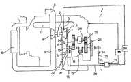
- FIG. 1shows a diagram of a turbocompound engine in accordance with the present invention
- FIG. 2shows a block diagram of a control device of the FIG. 1 engine.
- Number 1 in FIG. 1indicates as a whole an internal combustion engine for an industrial vehicle.
- Engine 1comprises a turbocharger 2 comprising a turbine 3 and a compressor 4 fitted to a common shaft.
- Turbine 3has an inlet 5 connected to an exhaust manifold 6 of engine 1 , and an outlet 7 .
- Compressor 4has an inlet connected to an air intake circuit 8 , and an outlet 9 connected to an intake manifold (not shown) of the engine via an intercooler 10 .
- Engine 1also comprises an auxiliary or power turbine 13 having an inlet 14 connected to outlet 7 of turbine 3 , and an outlet 15 connected to an exhaust system 16 .
- Auxiliary turbine 13is fitted to a shaft 18 , which is connected mechanically to a drive shaft 19 of engine 1 by a transmission indicated as a whole by 20.
- transmission 20comprises a first gear reducer 24 ; a hydraulic joint 25 ; and a second gear reducer 26 connected at the output to drive shaft 19 .
- an angular speed sensor 28e.g. comprising a pulse generating wheel 29 associated with shaft 18 or any other member rotating at fixed speed with respect to it—detects the rotation speed of auxiliary turbine 13 , is connected to a first input 30 of a device 31 for controlling fuel supply and the geometry of turbine 3 , and supplies input 30 with a signal I 1 related to the speed of auxiliary turbine 13 .
- a second sensor 34of conventional type (not shown) and associated, for example, with the input shaft of the vehicle transmission to detect the angular speed of the drive shaft (hereinafter referred to simply as “engine speed”, is connected to and supplies a second input 35 of device 31 with a signal I 2 .
- FIG. 2shows a block diagram of device 31 .
- Device 31substantially comprises a first block 36 for calculating the theoretical speed nTCteor of auxiliary turbine 13 on the basis of signal I 2 .
- Block 36is connected to second input 35 , substantially comprises a multiplier for multiplying the engine speed value by a constant taking into account the transmission ratio of transmission 20 , and is connected at the output to a block 37 , which compares the actual speed of the auxiliary turbine with a range of permissible values defined on the basis of the theoretical speed calculated above.
- block 37comprises a first adder 40 , which calculates a theoretical maximum speed nTCmax of auxiliary turbine 13 by adding a constant (e.g.
- nTCmin10,000 rpm to nTCteor
- second adder 41which calculates a theoretical minimum speed nTCmin of auxiliary turbine 13 by subtracting a constant (e.g. 20,000 rpm) from nTCteor.
- the two values nTCmax and nTCminare supplied to a first threshold comparator 42 defining a range of permissible values of the speed nTC of auxiliary turbine 13 .
- Speed nTCis calculated in known manner, on the basis of signal I 1 from sensor 28 , in an interface block 43 connected to first input 30 of device 31 , and which also generates in known manner a diagnostic signal 44 indicating the operating state of sensor 28 , and having, for example, a 0 logic value when sensor 28 is operating correctly, and a 1 logic value in the event signal I 1 of sensor 28 is implausible, e.g. absent or inevaluable.
- Threshold comparator 42receives signal nTC from interface block 43 , and compares it with threshold values nTCmax and nTCmin. More specifically, threshold comparator 42 generates a digital signal 45 of value 1 if nTC is between nTCmax and nTCmin, and of value 0 if nTC is outside the range defined by nTCmax and nTCmin.
- Signal 45is supplied to one input of a first AND gate 46 , the other input of which is supplied with a signal 47 equal to diagnostic signal 44 inverted by a NOT gate 48 .
- the output of AND gate 46is connected to a time filtering block 50 , which generates a signal 53 of the same logic value as the input signal when the input signal remains stable for a predetermined time interval.
- Signal 53is supplied to a reset input 54 of a flip-flop 55 .
- the nTCmax value calculated by first adding block 40is used to set the switching threshold of a second threshold comparator 54 , which receives signal nTC generated by interface block 43 , and generates a signal 56 of logic value 1 if nTC is greater than nTCmax, thus indicating a malfunction of auxiliary turbine 13 , and of logic value 0 if nTC is less than nTCmax.
- Output signal 56 from comparator 54 and output signal 47 from NOT gate 48are supplied to the inputs of a second AND gate 57 .
- the output of AND gate 57is connected to a second time filtering block 58 , which generates a signal 59 of the same logic value as the input signal when the input signal remains stable for a predetermined time interval.
- Signal 59is supplied to the set input 60 of flip-flop 55 .
- Flip-flop 55generates an output signal O 1 , which is supplied to a block 38 for controlling the geometry of turbine 3 , and to a block 39 for controlling fuel supply by the injectors.
- Block 39operation of which is described in detail later on, also receives signal nTC relative to the speed of auxiliary turbine 13 .
- sensor 28is assumed to be operating correctly, so that signal 44 is of value 1 and has no effect on the outputs of AND gates 46 , 57 , which depend exclusively on the value of nTC.
- nTCfalls within the range of permissible values, the condition nTC ⁇ nTCmax is also definitely confirmed, so that the output of second threshold comparator 54 is 0, the output of second AND gate 57 is 0, and, if this value remains stable over time, the set input of flip-flop 55 is also 0.
- the output signal O 1 of flip-flop 55is zero, so there is no intervention on the part of blocks 38 , 39 .
- nTCis greater than nTCmax, the output of second threshold comparator 54 is 1, the output of second AND gate 57 is 1, and, if this value remains stable over time, the set input of flip-flop 55 is also 1.
- signal O 1equals 1 and a correction of the geometry of turbine 3 and fuel supply is enabled.
- the lower branch 31 b of the block diagramtherefore acts as a recognition circuit for determining a malfunction.
- block 38sets the geometry of turbine 3 to the full-open condition, thus reducing supercharging; and, at the same time, block 39 immediately reduces fuel supply by the injectors to a predetermined start value, and then modulates the full supply value to keep the speed of auxiliary turbine 13 constant and equal to an acceptable value, e.g. nTCmax.
- the control logic of device 31only provides for correcting the operating parameters of the engine (geometry of turbine 3 and fuel supply) when the integrity of auxiliary turbine 13 is definitely at risk. That is, it does not intervene when the fault may possibly depend on a malfunction of sensor 28 , or when the fault does not threaten the integrity of turbine 13 (nTC ⁇ nTCmin).
- interventionis designed to still allow albeit emergency operation of the vehicle, by supply to the engine being controlled to prevent overacceleration of auxiliary turbine 13 .
Landscapes
- Engineering & Computer Science (AREA)
- Chemical & Material Sciences (AREA)
- Combustion & Propulsion (AREA)
- Mechanical Engineering (AREA)
- General Engineering & Computer Science (AREA)
- Supercharger (AREA)
- Acyclic And Carbocyclic Compounds In Medicinal Compositions (AREA)
- Output Control And Ontrol Of Special Type Engine (AREA)
- Structures Of Non-Positive Displacement Pumps (AREA)
Abstract
Description
Claims (9)
Applications Claiming Priority (2)
| Application Number | Priority Date | Filing Date | Title |
|---|---|---|---|
| IT2000TO000940AIT1320703B1 (en) | 2000-10-06 | 2000-10-06 | TURBOCOMPOUND ENDOTHERMAL ENGINE. |
| ITTO2000A000940 | 2000-10-06 |
Publications (2)
| Publication Number | Publication Date |
|---|---|
| US20020062646A1 US20020062646A1 (en) | 2002-05-30 |
| US6681575B2true US6681575B2 (en) | 2004-01-27 |
Family
ID=11458100
Family Applications (1)
| Application Number | Title | Priority Date | Filing Date |
|---|---|---|---|
| US09/971,817Expired - Fee RelatedUS6681575B2 (en) | 2000-10-06 | 2001-10-05 | Turbocompound internal combustion engine |
Country Status (7)
| Country | Link |
|---|---|
| US (1) | US6681575B2 (en) |
| EP (1) | EP1195502B1 (en) |
| JP (1) | JP4064650B2 (en) |
| AT (1) | ATE288540T1 (en) |
| DE (1) | DE60108699T2 (en) |
| ES (1) | ES2236108T3 (en) |
| IT (1) | IT1320703B1 (en) |
Cited By (15)
| Publication number | Priority date | Publication date | Assignee | Title |
|---|---|---|---|---|
| US20080011070A1 (en)* | 2006-06-30 | 2008-01-17 | International Engine Intellectual Property Company, Llc | Turbocharger performance qualification method and apparatus |
| US20080110169A1 (en)* | 2006-11-01 | 2008-05-15 | Young Jun Roh | System and method for controlling minimum flow rate of variable geometry turbocharger |
| US20100083655A1 (en)* | 2006-09-29 | 2010-04-08 | Frederick Mark S | Turbocharger system and method |
| US20110172894A1 (en)* | 2007-08-10 | 2011-07-14 | Tjerk Michiel De Graaff | Method of operation of an electric turbocompounding system |
| US20110239642A1 (en)* | 2010-11-03 | 2011-10-06 | Schwiesow Paul A | Double-Acting, Two-Stroke HCCI Compound Free-Piston Rotating-Shaft Engine |
| US20120186248A1 (en)* | 2010-07-26 | 2012-07-26 | Vandyne Ed | Superturbocharger control systems |
| US9534534B2 (en) | 2013-08-28 | 2017-01-03 | Deere & Company | Power system including a variable geometry turbocompound turbine |
| US9869240B2 (en) | 2015-02-20 | 2018-01-16 | Pratt & Whitney Canada Corp. | Compound engine assembly with cantilevered compressor and turbine |
| US10371060B2 (en) | 2015-02-20 | 2019-08-06 | Pratt & Whitney Canada Corp. | Compound engine assembly with confined fire zone |
| US10384525B2 (en) | 2017-02-02 | 2019-08-20 | FEV Europe GmbH | Systems for power integration of turbines, compressors and hybrid energy devices with internal combustion engines |
| US10408123B2 (en) | 2015-02-20 | 2019-09-10 | Pratt & Whitney Canada Corp. | Engine assembly with modular compressor and turbine |
| US10428734B2 (en) | 2015-02-20 | 2019-10-01 | Pratt & Whitney Canada Corp. | Compound engine assembly with inlet lip anti-icing |
| US10533500B2 (en) | 2015-02-20 | 2020-01-14 | Pratt & Whitney Canada Corp. | Compound engine assembly with mount cage |
| US10533492B2 (en) | 2015-02-20 | 2020-01-14 | Pratt & Whitney Canada Corp. | Compound engine assembly with mount cage |
| US10677154B2 (en) | 2015-02-20 | 2020-06-09 | Pratt & Whitney Canada Corp. | Compound engine assembly with offset turbine shaft, engine shaft and inlet duct |
Families Citing this family (14)
| Publication number | Priority date | Publication date | Assignee | Title |
|---|---|---|---|---|
| JP2006299938A (en)* | 2005-04-21 | 2006-11-02 | Hino Motors Ltd | Turbo compound system |
| JP4502277B2 (en)* | 2006-06-12 | 2010-07-14 | ヤンマー株式会社 | Engine with turbocharger |
| ITMI20061479A1 (en)* | 2006-07-27 | 2008-01-28 | Iveco Spa | MOTOR WITH ENERGY RECOVERY AND CATALYTIC SYSTEM OF DISCHARGE GAS TREATMENT |
| EP2235334B1 (en)* | 2007-12-21 | 2013-05-29 | Renault Trucks | Arrangement for an exhaust line of an internal combustion engine |
| US8302398B2 (en)* | 2008-08-29 | 2012-11-06 | Deere & Company | Work machine with drive train coupled turbo compounding |
| US20120227397A1 (en)* | 2011-03-10 | 2012-09-13 | Willi Martin L | Gaseous fuel-powered engine system having turbo-compounding |
| RU2600839C2 (en)* | 2011-05-30 | 2016-10-27 | Фпт Моторенфоршунг Аг | Hybrid turbo-compound supercharged engine |
| CN102562273B (en)* | 2012-02-13 | 2014-01-08 | 清华大学 | Turbo compound device with variable geometry turbocharger and its engine system |
| CN104314649A (en)* | 2014-09-30 | 2015-01-28 | 东风商用车有限公司 | Waste gas bypass power turbine system |
| BR102017008570A2 (en)* | 2017-04-26 | 2018-11-21 | Associacao Paranaense De Cultura - Apc | diesel and binary-isobaric-adiabatic combined cycle engine and process control for the thermodynamic cycle of the combined cycle engine |
| BR102017008580A2 (en)* | 2017-04-26 | 2018-11-21 | Associacao Paranaense De Cultura - Apc | otto and binary-isothermal-adiabatic combined-cycle motor and control process for the thermodynamic cycle of the combined-cycle motor |
| BR102017008573A2 (en)* | 2017-04-26 | 2018-11-21 | Associacao Paranaense De Cultura - Apc | diesel and torque-isothermal-adiabatic combined cycle engine and process control for thermodynamic cycle of combined cycle engine |
| BR102017008576A2 (en)* | 2017-04-26 | 2018-11-21 | Associacao Paranaense De Cultura - Apc | otto and binary-isobaric-adiabatic combined-cycle motor and process control for the thermodynamic cycle of the combined-cycle motor |
| BR102017008585A2 (en)* | 2017-04-26 | 2018-11-21 | Associacao Paranaense De Cultura - Apc | atkinson or miller and torque-isothermal-adiabatic combined-cycle engine and control process for the thermodynamic cycle of the combined-cycle engine |
Citations (8)
| Publication number | Priority date | Publication date | Assignee | Title |
|---|---|---|---|---|
| US4452043A (en)* | 1980-07-22 | 1984-06-05 | South Western Industrial Research Limited | Differential compound engine |
| US4884407A (en) | 1987-10-28 | 1989-12-05 | Isuzu Motors Limited | Turbo compound engine |
| EP0420705A1 (en) | 1989-09-29 | 1991-04-03 | Isuzu Motors Limited | Complex turbocharger compound engine system |
| US5119633A (en)* | 1990-09-25 | 1992-06-09 | Cummins Engine Company, Inc. | Power turbine bypass for improved compression braking |
| US5142868A (en)* | 1990-11-30 | 1992-09-01 | Cummins Engine Company, Inc. | Turbocompound engine with power turbine bypass control |
| US5555730A (en) | 1994-10-24 | 1996-09-17 | Haeco Partners, Ltd. | Cooling for gas turbine-two stroke piston compound engine |
| US5884482A (en)* | 1994-05-13 | 1999-03-23 | Scania Cv Aktiebolag | Combustion engine of turbocompound type with exhaust gas brake |
| US6286312B1 (en)* | 1997-12-03 | 2001-09-11 | Volvo Lastvagnar Ab | Arrangement for a combustion engine |
- 2000
- 2000-10-06ITIT2000TO000940Apatent/IT1320703B1/enactive
- 2001
- 2001-10-05USUS09/971,817patent/US6681575B2/ennot_activeExpired - Fee Related
- 2001-10-05EPEP01123905Apatent/EP1195502B1/ennot_activeExpired - Lifetime
- 2001-10-05ATAT01123905Tpatent/ATE288540T1/ennot_activeIP Right Cessation
- 2001-10-05ESES01123905Tpatent/ES2236108T3/ennot_activeExpired - Lifetime
- 2001-10-05DEDE60108699Tpatent/DE60108699T2/ennot_activeExpired - Lifetime
- 2001-10-09JPJP2001311671Apatent/JP4064650B2/ennot_activeExpired - Fee Related
Patent Citations (8)
| Publication number | Priority date | Publication date | Assignee | Title |
|---|---|---|---|---|
| US4452043A (en)* | 1980-07-22 | 1984-06-05 | South Western Industrial Research Limited | Differential compound engine |
| US4884407A (en) | 1987-10-28 | 1989-12-05 | Isuzu Motors Limited | Turbo compound engine |
| EP0420705A1 (en) | 1989-09-29 | 1991-04-03 | Isuzu Motors Limited | Complex turbocharger compound engine system |
| US5119633A (en)* | 1990-09-25 | 1992-06-09 | Cummins Engine Company, Inc. | Power turbine bypass for improved compression braking |
| US5142868A (en)* | 1990-11-30 | 1992-09-01 | Cummins Engine Company, Inc. | Turbocompound engine with power turbine bypass control |
| US5884482A (en)* | 1994-05-13 | 1999-03-23 | Scania Cv Aktiebolag | Combustion engine of turbocompound type with exhaust gas brake |
| US5555730A (en) | 1994-10-24 | 1996-09-17 | Haeco Partners, Ltd. | Cooling for gas turbine-two stroke piston compound engine |
| US6286312B1 (en)* | 1997-12-03 | 2001-09-11 | Volvo Lastvagnar Ab | Arrangement for a combustion engine |
Cited By (22)
| Publication number | Priority date | Publication date | Assignee | Title |
|---|---|---|---|---|
| US20080011070A1 (en)* | 2006-06-30 | 2008-01-17 | International Engine Intellectual Property Company, Llc | Turbocharger performance qualification method and apparatus |
| US7380445B2 (en)* | 2006-06-30 | 2008-06-03 | International Engine Intellectual Property Company, Llc | Turbocharger performance qualification method and apparatus |
| WO2008005679A3 (en)* | 2006-06-30 | 2008-12-18 | Int Engine Intellectual Prop | Turbocharger performance qualification method and apparatus |
| US20100083655A1 (en)* | 2006-09-29 | 2010-04-08 | Frederick Mark S | Turbocharger system and method |
| US20080110169A1 (en)* | 2006-11-01 | 2008-05-15 | Young Jun Roh | System and method for controlling minimum flow rate of variable geometry turbocharger |
| US7805938B2 (en)* | 2006-11-01 | 2010-10-05 | Hyundai Motor Company | System and method for controlling minimum flow rate of variable geometry turbocharger |
| US8364378B2 (en)* | 2007-08-10 | 2013-01-29 | Bowman Power Group Limited | Method of operation of an electric turbocompounding system |
| US20110172894A1 (en)* | 2007-08-10 | 2011-07-14 | Tjerk Michiel De Graaff | Method of operation of an electric turbocompounding system |
| US20120186248A1 (en)* | 2010-07-26 | 2012-07-26 | Vandyne Ed | Superturbocharger control systems |
| US8769949B2 (en)* | 2010-07-26 | 2014-07-08 | Vandyne Superturbo, Inc. | Superturbocharger control systems |
| US20110239642A1 (en)* | 2010-11-03 | 2011-10-06 | Schwiesow Paul A | Double-Acting, Two-Stroke HCCI Compound Free-Piston Rotating-Shaft Engine |
| US8127544B2 (en)* | 2010-11-03 | 2012-03-06 | Paul Albert Schwiesow | Two-stroke HCCI compound free-piston/gas-turbine engine |
| US9534534B2 (en) | 2013-08-28 | 2017-01-03 | Deere & Company | Power system including a variable geometry turbocompound turbine |
| US9869240B2 (en) | 2015-02-20 | 2018-01-16 | Pratt & Whitney Canada Corp. | Compound engine assembly with cantilevered compressor and turbine |
| US10371060B2 (en) | 2015-02-20 | 2019-08-06 | Pratt & Whitney Canada Corp. | Compound engine assembly with confined fire zone |
| US10408123B2 (en) | 2015-02-20 | 2019-09-10 | Pratt & Whitney Canada Corp. | Engine assembly with modular compressor and turbine |
| US10428734B2 (en) | 2015-02-20 | 2019-10-01 | Pratt & Whitney Canada Corp. | Compound engine assembly with inlet lip anti-icing |
| US10533500B2 (en) | 2015-02-20 | 2020-01-14 | Pratt & Whitney Canada Corp. | Compound engine assembly with mount cage |
| US10533492B2 (en) | 2015-02-20 | 2020-01-14 | Pratt & Whitney Canada Corp. | Compound engine assembly with mount cage |
| US10598086B2 (en) | 2015-02-20 | 2020-03-24 | Pratt & Whitney Canada Corp. | Compound engine assembly with cantilevered compressor and turbine |
| US10677154B2 (en) | 2015-02-20 | 2020-06-09 | Pratt & Whitney Canada Corp. | Compound engine assembly with offset turbine shaft, engine shaft and inlet duct |
| US10384525B2 (en) | 2017-02-02 | 2019-08-20 | FEV Europe GmbH | Systems for power integration of turbines, compressors and hybrid energy devices with internal combustion engines |
Also Published As
| Publication number | Publication date |
|---|---|
| ITTO20000940A0 (en) | 2000-10-06 |
| EP1195502A1 (en) | 2002-04-10 |
| IT1320703B1 (en) | 2003-12-10 |
| DE60108699T2 (en) | 2006-01-19 |
| ES2236108T3 (en) | 2005-07-16 |
| EP1195502B1 (en) | 2005-02-02 |
| ITTO20000940A1 (en) | 2002-04-06 |
| ATE288540T1 (en) | 2005-02-15 |
| JP4064650B2 (en) | 2008-03-19 |
| DE60108699D1 (en) | 2005-03-10 |
| JP2002201952A (en) | 2002-07-19 |
| US20020062646A1 (en) | 2002-05-30 |
Similar Documents
| Publication | Publication Date | Title |
|---|---|---|
| US6681575B2 (en) | Turbocompound internal combustion engine | |
| RU2401388C2 (en) | Engine with supercharger (versions) | |
| US7509210B2 (en) | Abnormality determination apparatus and method for blow-by gas feedback device, and engine control unit | |
| US5987888A (en) | System and method for controlling a turbocharger | |
| JP5707967B2 (en) | Supercharging pressure diagnosis device for internal combustion engine | |
| EP0769612B1 (en) | Apparatus for detecting intake pressure abnormalities in an engine | |
| EP2562403A1 (en) | Fault diagnosis apparatus for airflow meter | |
| CN105927405B (en) | Method and device for starting a drive system of a motor vehicle | |
| JPH04269364A (en) | EGR control device failure diagnosis device | |
| JP2009221881A (en) | Engine | |
| WO2000058615A1 (en) | Device and method for controlling fuel injection amount of internal combustion engine with turbocharger | |
| JP5538712B2 (en) | EGR device for internal combustion engine | |
| JP3721671B2 (en) | Fault diagnosis device for vehicles | |
| US6314733B1 (en) | Control method | |
| JP4518045B2 (en) | Control device for an internal combustion engine with a supercharger | |
| US8229654B2 (en) | Device for limiting output of internal combustion engine when the engine has abnormality | |
| JP2010151040A (en) | Abnormality detection device of intercooler | |
| US20170363025A1 (en) | Control apparatus for internal combustion engine | |
| JP2007009877A (en) | Abnormality diagnostic device for supercharging pressure control system | |
| JPH01208546A (en) | Device for detecting failure of intake system of engine | |
| JP2008190410A (en) | Self-diagnosis device for variable valve timing control device | |
| JPH10122020A (en) | Control device for supercharged engine | |
| JPS6248935A (en) | Abnormality determination device for internal combustion engine with supercharger | |
| JPS61237846A (en) | Control device for supercharge pressure in internal-combustion engine with supercharger | |
| JPH02185627A (en) | Control device for two-shaft gas turbine engine |
Legal Events
| Date | Code | Title | Description |
|---|---|---|---|
| AS | Assignment | Owner name:IVECO FIAT S.P.A., ITALY Free format text:ASSIGNMENT OF ASSIGNORS INTEREST;ASSIGNORS:DELLORA, GIANCARLO;ZAEHNER, WERNER;REEL/FRAME:012564/0397 Effective date:20020110 Owner name:IVECO MOTORENFORSCHUNG AG, SWITZERLAND Free format text:ASSIGNMENT OF ASSIGNORS INTEREST;ASSIGNORS:DELLORA, GIANCARLO;ZAEHNER, WERNER;REEL/FRAME:012564/0397 Effective date:20020110 | |
| AS | Assignment | Owner name:IVECO S.P.A. SOCIETA PER AZIONI, ITALY Free format text:CHANGE OF NAME;ASSIGNOR:IVECO FIAT S.P.A.;REEL/FRAME:017655/0673 Effective date:20040630 | |
| FPAY | Fee payment | Year of fee payment:4 | |
| FPAY | Fee payment | Year of fee payment:8 | |
| AS | Assignment | Owner name:NUOVA IMMOBILIARE NOVE S.P.A, ITALY Free format text:ASSIGNMENT OF ASSIGNORS INTEREST;ASSIGNOR:IVECO S.P.A;REEL/FRAME:027076/0278 Effective date:20100629 | |
| AS | Assignment | Owner name:FIAT POWERTRAIN TECHNOLOGIES INDUSTRIAL S.P.A, ITA Free format text:CHANGE OF NAME;ASSIGNOR:NUOVA IMMOBILIARE NOVE S.P.A.;REEL/FRAME:027182/0924 Effective date:20101001 | |
| AS | Assignment | Owner name:FPT MOTORENFORSCHUNG AG, SWITZERLAND Free format text:CHANGE OF NAME;ASSIGNOR:ICEVO MOTORENFORSCHUNG AG;REEL/FRAME:029777/0681 Effective date:20121101 | |
| REMI | Maintenance fee reminder mailed | ||
| LAPS | Lapse for failure to pay maintenance fees | ||
| STCH | Information on status: patent discontinuation | Free format text:PATENT EXPIRED DUE TO NONPAYMENT OF MAINTENANCE FEES UNDER 37 CFR 1.362 | |
| FP | Lapsed due to failure to pay maintenance fee | Effective date:20160127 |